EP4421564A2 - Toner container having positioning features for electrical contacts - Google Patents
Toner container having positioning features for electrical contacts Download PDFInfo
- Publication number
- EP4421564A2 EP4421564A2 EP24159213.8A EP24159213A EP4421564A2 EP 4421564 A2 EP4421564 A2 EP 4421564A2 EP 24159213 A EP24159213 A EP 24159213A EP 4421564 A2 EP4421564 A2 EP 4421564A2
- Authority
- EP
- European Patent Office
- Prior art keywords
- toner container
- image forming
- forming device
- electrical connector
- toner
- Prior art date
- Legal status (The legal status is an assumption and is not a legal conclusion. Google has not performed a legal analysis and makes no representation as to the accuracy of the status listed.)
- Pending
Links
Images





Classifications
-
- G—PHYSICS
- G03—PHOTOGRAPHY; CINEMATOGRAPHY; ANALOGOUS TECHNIQUES USING WAVES OTHER THAN OPTICAL WAVES; ELECTROGRAPHY; HOLOGRAPHY
- G03G—ELECTROGRAPHY; ELECTROPHOTOGRAPHY; MAGNETOGRAPHY
- G03G15/00—Apparatus for electrographic processes using a charge pattern
- G03G15/06—Apparatus for electrographic processes using a charge pattern for developing
- G03G15/08—Apparatus for electrographic processes using a charge pattern for developing using a solid developer, e.g. powder developer
- G03G15/0822—Arrangements for preparing, mixing, supplying or dispensing developer
- G03G15/0863—Arrangements for preparing, mixing, supplying or dispensing developer provided with identifying means or means for storing process- or use parameters, e.g. an electronic memory
-
- G—PHYSICS
- G03—PHOTOGRAPHY; CINEMATOGRAPHY; ANALOGOUS TECHNIQUES USING WAVES OTHER THAN OPTICAL WAVES; ELECTROGRAPHY; HOLOGRAPHY
- G03G—ELECTROGRAPHY; ELECTROPHOTOGRAPHY; MAGNETOGRAPHY
- G03G15/00—Apparatus for electrographic processes using a charge pattern
- G03G15/06—Apparatus for electrographic processes using a charge pattern for developing
- G03G15/08—Apparatus for electrographic processes using a charge pattern for developing using a solid developer, e.g. powder developer
- G03G15/0822—Arrangements for preparing, mixing, supplying or dispensing developer
- G03G15/0865—Arrangements for supplying new developer
- G03G15/0875—Arrangements for supplying new developer cartridges having a box like shape
-
- G—PHYSICS
- G03—PHOTOGRAPHY; CINEMATOGRAPHY; ANALOGOUS TECHNIQUES USING WAVES OTHER THAN OPTICAL WAVES; ELECTROGRAPHY; HOLOGRAPHY
- G03G—ELECTROGRAPHY; ELECTROPHOTOGRAPHY; MAGNETOGRAPHY
- G03G15/00—Apparatus for electrographic processes using a charge pattern
- G03G15/80—Details relating to power supplies, circuits boards, electrical connections
-
- G—PHYSICS
- G03—PHOTOGRAPHY; CINEMATOGRAPHY; ANALOGOUS TECHNIQUES USING WAVES OTHER THAN OPTICAL WAVES; ELECTROGRAPHY; HOLOGRAPHY
- G03G—ELECTROGRAPHY; ELECTROPHOTOGRAPHY; MAGNETOGRAPHY
- G03G21/00—Arrangements not provided for by groups G03G13/00 - G03G19/00, e.g. cleaning, elimination of residual charge
- G03G21/16—Mechanical means for facilitating the maintenance of the apparatus, e.g. modular arrangements
- G03G21/1661—Mechanical means for facilitating the maintenance of the apparatus, e.g. modular arrangements means for handling parts of the apparatus in the apparatus
- G03G21/1676—Mechanical means for facilitating the maintenance of the apparatus, e.g. modular arrangements means for handling parts of the apparatus in the apparatus for the developer unit
-
- G—PHYSICS
- G03—PHOTOGRAPHY; CINEMATOGRAPHY; ANALOGOUS TECHNIQUES USING WAVES OTHER THAN OPTICAL WAVES; ELECTROGRAPHY; HOLOGRAPHY
- G03G—ELECTROGRAPHY; ELECTROPHOTOGRAPHY; MAGNETOGRAPHY
- G03G21/00—Arrangements not provided for by groups G03G13/00 - G03G19/00, e.g. cleaning, elimination of residual charge
- G03G21/16—Mechanical means for facilitating the maintenance of the apparatus, e.g. modular arrangements
- G03G21/1642—Mechanical means for facilitating the maintenance of the apparatus, e.g. modular arrangements for connecting the different parts of the apparatus
- G03G21/1647—Mechanical connection means
-
- G—PHYSICS
- G03—PHOTOGRAPHY; CINEMATOGRAPHY; ANALOGOUS TECHNIQUES USING WAVES OTHER THAN OPTICAL WAVES; ELECTROGRAPHY; HOLOGRAPHY
- G03G—ELECTROGRAPHY; ELECTROPHOTOGRAPHY; MAGNETOGRAPHY
- G03G21/00—Arrangements not provided for by groups G03G13/00 - G03G19/00, e.g. cleaning, elimination of residual charge
- G03G21/16—Mechanical means for facilitating the maintenance of the apparatus, e.g. modular arrangements
- G03G21/1642—Mechanical means for facilitating the maintenance of the apparatus, e.g. modular arrangements for connecting the different parts of the apparatus
- G03G21/1652—Electrical connection means
-
- G—PHYSICS
- G03—PHOTOGRAPHY; CINEMATOGRAPHY; ANALOGOUS TECHNIQUES USING WAVES OTHER THAN OPTICAL WAVES; ELECTROGRAPHY; HOLOGRAPHY
- G03G—ELECTROGRAPHY; ELECTROPHOTOGRAPHY; MAGNETOGRAPHY
- G03G21/00—Arrangements not provided for by groups G03G13/00 - G03G19/00, e.g. cleaning, elimination of residual charge
- G03G21/16—Mechanical means for facilitating the maintenance of the apparatus, e.g. modular arrangements
- G03G21/18—Mechanical means for facilitating the maintenance of the apparatus, e.g. modular arrangements using a processing cartridge, whereby the process cartridge comprises at least two image processing means in a single unit
- G03G21/1839—Means for handling the process cartridge in the apparatus body
- G03G21/1842—Means for handling the process cartridge in the apparatus body for guiding and mounting the process cartridge, positioning, alignment, locks
- G03G21/185—Means for handling the process cartridge in the apparatus body for guiding and mounting the process cartridge, positioning, alignment, locks the process cartridge being mounted parallel to the axis of the photosensitive member
-
- G—PHYSICS
- G03—PHOTOGRAPHY; CINEMATOGRAPHY; ANALOGOUS TECHNIQUES USING WAVES OTHER THAN OPTICAL WAVES; ELECTROGRAPHY; HOLOGRAPHY
- G03G—ELECTROGRAPHY; ELECTROPHOTOGRAPHY; MAGNETOGRAPHY
- G03G2215/00—Apparatus for electrophotographic processes
- G03G2215/06—Developing structures, details
- G03G2215/066—Toner cartridge or other attachable and detachable container for supplying developer material to replace the used material
- G03G2215/0663—Toner cartridge or other attachable and detachable container for supplying developer material to replace the used material having a longitudinal rotational axis, around which at least one part is rotated when mounting or using the cartridge
- G03G2215/0665—Generally horizontally mounting of said toner cartridge parallel to its longitudinal rotational axis
-
- G—PHYSICS
- G03—PHOTOGRAPHY; CINEMATOGRAPHY; ANALOGOUS TECHNIQUES USING WAVES OTHER THAN OPTICAL WAVES; ELECTROGRAPHY; HOLOGRAPHY
- G03G—ELECTROGRAPHY; ELECTROPHOTOGRAPHY; MAGNETOGRAPHY
- G03G2215/00—Apparatus for electrophotographic processes
- G03G2215/06—Developing structures, details
- G03G2215/066—Toner cartridge or other attachable and detachable container for supplying developer material to replace the used material
- G03G2215/068—Toner cartridge or other attachable and detachable container for supplying developer material to replace the used material having a box like shape
-
- G—PHYSICS
- G03—PHOTOGRAPHY; CINEMATOGRAPHY; ANALOGOUS TECHNIQUES USING WAVES OTHER THAN OPTICAL WAVES; ELECTROGRAPHY; HOLOGRAPHY
- G03G—ELECTROGRAPHY; ELECTROPHOTOGRAPHY; MAGNETOGRAPHY
- G03G2221/00—Processes not provided for by group G03G2215/00, e.g. cleaning or residual charge elimination
- G03G2221/16—Mechanical means for facilitating the maintenance of the apparatus, e.g. modular arrangements and complete machine concepts
- G03G2221/1651—Mechanical means for facilitating the maintenance of the apparatus, e.g. modular arrangements and complete machine concepts for connecting the different parts
- G03G2221/1657—Mechanical means for facilitating the maintenance of the apparatus, e.g. modular arrangements and complete machine concepts for connecting the different parts transmitting mechanical drive power
-
- G—PHYSICS
- G03—PHOTOGRAPHY; CINEMATOGRAPHY; ANALOGOUS TECHNIQUES USING WAVES OTHER THAN OPTICAL WAVES; ELECTROGRAPHY; HOLOGRAPHY
- G03G—ELECTROGRAPHY; ELECTROPHOTOGRAPHY; MAGNETOGRAPHY
- G03G2221/00—Processes not provided for by group G03G2215/00, e.g. cleaning or residual charge elimination
- G03G2221/16—Mechanical means for facilitating the maintenance of the apparatus, e.g. modular arrangements and complete machine concepts
- G03G2221/1651—Mechanical means for facilitating the maintenance of the apparatus, e.g. modular arrangements and complete machine concepts for connecting the different parts
- G03G2221/166—Electrical connectors
Definitions
- the present disclosure relates generally to image forming devices and more particularly to a toner container having positioning features for electrical contacts.
- an electrically charged rotating photoconductive drum is selectively exposed to a laser beam.
- the areas of the photoconductive drum exposed to the laser beam are discharged, creating an electrostatic latent image of a page to be printed on the photoconductive drum.
- Toner particles are then electrostatically picked up by the latent image on the photoconductive drum, creating a toned image on the drum.
- the toned image is transferred to the print media (e.g., paper) either directly by the photoconductive drum or indirectly by an intermediate transfer member.
- the toner is then fused to the media using heat and pressure to complete the print.
- the alignment guide includes a side guide having an inner side contact surface for contacting the electrical connector of the image forming device during insertion of the toner container into the image forming device to move the electrical connector of the image forming device relative to the toner container in a direction away from the first side of the body and toward the second side of the body during insertion of the toner container into the image forming device with the first end of the body leading.
- the bottom contact surface of the upper guide is positioned higher than the electrical contact of the toner container.
- the inner side contact surface of the side guide is positioned lower than the bottom contact surface of the upper guide and closer to the first side of the body than the electrical contact of the toner container is to the first side of the body.
- Embodiments include those wherein the electrical contact of the toner container is aligned with the drive coupler of the toner container along a vertical dimension of the toner container.
- the upper guide is aligned with the electrical contact of the toner container along the vertical dimension of the toner container.
- Embodiments include those wherein the first end of the body includes an end cap mounted to an end wall of the body, and the alignment guide is formed integrally with the end cap.
- Embodiments include those wherein the upper guide includes a horizontal projection from the first end of the body above the electrical contact of the toner container.
- the side guide includes a vertical projection from the first end of the body.
- Embodiments include those wherein the inner side contact surface of the side guide is positioned closer to the first side of the body than to the second side of the body.
- the side guide extends downward from the upper guide.
- Embodiments include those wherein the alignment guide extends further in a direction from the second end of the body toward the first end of the body than the electrical contact of the toner container.
- the alignment guide forms a leading edge of the toner container in a direction from the second end of the body toward the first end of the body.
- Embodiments include those wherein the electrical contact of the toner container is electrically connected to processing circuitry positioned on the toner container.
- a toner container for use in an image forming device includes a body having a top, a bottom, a first side and a second side positioned between a first longitudinal end and a second longitudinal end of the body.
- the first longitudinal end of the body leads during insertion of the toner container into the image forming device, and the second longitudinal end trails during insertion of the toner container into the image forming device.
- a longitudinal dimension of the toner container that is orthogonal to a vertical dimension of the toner container extends between the first longitudinal end of the body and the second longitudinal end of the body.
- a side-to-side dimension of the toner container that is orthogonal to the longitudinal dimension of the toner container and the vertical dimension of the toner container extends between the first side of the body and the second side of the body.
- the body has a reservoir for holding toner.
- An outlet port is positioned on the bottom of the body and adjacent to the first longitudinal end of the body for exiting toner from the toner container.
- a drive coupler is positioned on the first longitudinal end of the body for mating with a corresponding drive coupler in the image forming device when the toner container is installed in the image forming device for receiving rotational motion from the corresponding drive coupler in the image forming device.
- the drive coupler of the toner container is positioned higher in the vertical dimension of the toner container than the outlet port.
- An electrical contact is positioned on the first longitudinal end of the body for contacting a corresponding electrical contact in the image forming device when the toner container is installed in the image forming device.
- the electrical contact of the toner container is electrically connected to processing circuitry positioned on the toner container.
- the electrical contact of the toner container is positioned higher in the vertical dimension of the toner container than the drive coupler of the toner container.
- An alignment guide is positioned on the first longitudinal end of the body.
- the alignment guide includes an upper guide having a bottom contact surface that is unobstructed to contact an electrical connector of the image forming device that includes the corresponding electrical contact of the image forming device during insertion of the toner container into the image forming device for moving the electrical connector of the image forming device downward relative to the toner container during insertion of the toner container into the image forming device with the first longitudinal end of the body leading in order to align the electrical connector of the image forming device with the electrical contact of the toner container in the vertical dimension of the toner container.
- the alignment guide includes a side guide having an inner side contact surface that is unobstructed to contact the electrical connector of the image forming device during insertion of the toner container into the image forming device for moving the electrical connector of the image forming device relative to the toner container along the side-to-side dimension of the toner container in a direction away from the first side of the body and toward the second side of the body during insertion of the toner container into the image forming device with the first longitudinal end of the body leading in order to align the electrical connector of the image forming device with the electrical contact of the toner container in the side-to-side dimension of the toner container.
- the bottom contact surface of the upper guide is positioned higher in the vertical dimension of the toner container than the electrical contact of the toner container and the inner side contact surface of the side guide.
- the inner side contact surface of the side guide is spaced along the side-to-side dimension of the toner container toward the first side of the body from the electrical contact of the toner container.
- Embodiments include those wherein the first longitudinal end of the body includes an end cap mounted to an end wall of the body, and the alignment guide is formed integrally with the end cap.
- Embodiments include those wherein the upper guide includes a horizontal projection from the first longitudinal end of the body above the electrical contact of the toner container.
- Embodiments include those wherein the side guide includes a vertical projection from the first longitudinal end of the body.
- Embodiments include those wherein the inner side contact surface of the side guide is positioned closer to the first side of the body than to the second side of the body.
- Embodiments include those wherein the side guide extends downward from the upper guide.
- Embodiments include those wherein the alignment guide extends further along the longitudinal dimension of the toner container in a direction from the second longitudinal end of the body toward the first longitudinal end of the body than the electrical contact of the toner container.
- Embodiments include those wherein the alignment guide forms a forward-most portion of the toner container along the longitudinal dimension of the toner container in a direction from the second longitudinal end of the body toward the first longitudinal end of the body.
- a toner container for use in an image forming device includes a body having a top, a bottom, a first side and a second side positioned between a first longitudinal end and a second longitudinal end of the body.
- the first longitudinal end of the body leads during insertion of the toner container into the image forming device, and the second longitudinal end trails during insertion of the toner container into the image forming device.
- a longitudinal dimension of the toner container extends between the first longitudinal end of the body and the second longitudinal end of the body.
- the body has a reservoir for holding toner.
- a drive coupler is positioned on the first longitudinal end of the body for mating with a corresponding drive coupler in the image forming device when the toner container is installed in the image forming device for receiving rotational motion from the corresponding drive coupler in the image forming device.
- An electrical contact is positioned on the first longitudinal end of the body for contacting a corresponding electrical contact in the image forming device when the toner container is installed in the image forming device.
- An alignment guide is positioned on the first longitudinal end of the body.
- the alignment guide includes a first guide having a first contact surface for contacting an electrical connector of the image forming device that includes the corresponding electrical contact of the image forming device during insertion of the toner container into the image forming device to move the electrical connector of the image forming device in a first direction relative to the toner container during insertion of the toner container into the image forming device to align the electrical connector of the image forming device with the electrical contact of the toner container in a first dimension of the toner container that is orthogonal to the longitudinal dimension of the toner container.
- the alignment guide includes a second guide having a second contact surface for contacting the electrical connector of the image forming device during insertion of the toner container into the image forming device to move the electrical connector of the image forming device in a second direction relative to the toner container during insertion of the toner container into the image forming device to align the electrical connector of the image forming device with the electrical contact of the toner container in a second dimension of the toner container that is orthogonal to the longitudinal dimension of the toner container and the first dimension of the toner container.
- the alignment guide forms a leading edge of the toner container along the longitudinal dimension of the toner container in a direction from the second longitudinal end of the body toward the first longitudinal end of the body.
- Embodiments include those wherein the first contact surface includes a bottom contact surface of the first guide for contacting the electrical connector of the image forming device during insertion of the toner container into the image forming device to move the electrical connector of the image forming device downward relative to the toner container during insertion of the toner container into the image forming device to align the electrical connector of the image forming device with the electrical contact of the toner container in a vertical dimension of the toner container that is orthogonal to the longitudinal dimension of the toner container, and the second contact surface includes a side contact surface for contacting the electrical connector of the image forming device during insertion of the toner container into the image forming device to move the electrical connector of the image forming device in the second direction relative to the toner container during insertion of the toner container into the image forming device to align the electrical connector of the image forming device with the electrical contact of the toner container in a side-to-side dimension of the toner container that is orthogonal to the longitudinal dimension of the toner container and the vertical dimension of the toner container
- Embodiments include those wherein the bottom contact surface of the first guide is positioned higher than the side contact surface of the second guide.
- Embodiments include those wherein the bottom contact surface of the first guide is positioned higher than the electrical contact of the toner container.
- Embodiments include those wherein the electrical contact of the toner container is positioned higher than the drive coupler of the toner container.
- Embodiments include those wherein the first longitudinal end of the body includes an end cap mounted to an end wall of the body, and the alignment guide is formed integrally with the end cap.
- Embodiments include those wherein the second guide extends orthogonally from the first guide.
- Embodiments include those wherein the electrical contact of the toner container is electrically connected to processing circuitry positioned on the toner container.
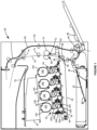
- FIG. 1 illustrates a schematic view of the interior of an example image forming device 20.
- Image forming device 20 includes a housing 22.
- Housing 22 includes one or more input trays 28 positioned therein.
- Each tray 28 is sized to contain a stack of media sheets.
- media is meant to encompass not only paper but also labels, envelopes, fabrics, photographic paper and any other desired substrate.
- Trays 28 are preferably removable for refilling.
- a control panel may be located on housing 22. Using the control panel, a user is able to enter commands and generally control the operation of image forming device 20. For example, a user may enter commands to switch modes (e.g., color mode, monochrome mode), view the number of images printed, etc.
- switch modes e.g., color mode, monochrome mode
- a media path 32 extends through image forming device 20 for moving the media sheets through the image transfer process.
- Media path 32 includes a simplex path 34 and may include a duplex path 36.
- a media sheet is introduced into simplex path 34 from tray 28 by a pick mechanism 38.
- pick mechanism 38 includes a roll positioned to move the media sheet from tray 28 and into media path 32. The media sheet is then moved along media path 32 by various transport rollers.
- Media sheets may also be introduced into media path 32 by a manual feed 46 having one or more rolls 48.
- Image forming device 20 includes an image transfer section that includes one or more imaging stations 50.
- Each imaging station 50 includes a toner cartridge 100, a developer unit 200 and a photoconductive unit (PC unit) 300.
- Each toner cartridge 100 includes a reservoir 102 for holding toner and an outlet port in communication with an inlet port of a corresponding developer unit 200 for transferring toner from reservoir 102 to developer unit 200 as discussed in greater detail below.
- developer unit 200 utilizes what is commonly referred to as a single component development system.
- each developer unit 200 includes a toner reservoir 202 and a toner adder roll 204 that moves toner from reservoir 202 to a developer roll 206.
- developer unit 200 utilizes what is commonly referred to as a dual component development system.
- toner in toner reservoir 202 is mixed with magnetic carrier beads.
- the magnetic carrier beads may be coated with a polymeric film to provide triboelectric properties to attract toner to the carrier beads as the toner and the magnetic carrier beads are mixed in the toner reservoir.
- developer roll 206 attracts the magnetic carrier beads having toner thereon to developer roll 206 through the use of magnetic fields.
- Each PC unit 300 includes a charging roll 304 and a photoconductive (PC) drum 302 for each imaging station 50. PC drums 302 are mounted substantially parallel to each other. For purposes of clarity, developer unit 200 and PC unit 300 are labeled on only one of the imaging stations 50 in Figure 1 . In the example embodiment illustrated, each imaging station 50 is substantially the same except for the color of toner contained therein.
- Each charging roll 304 forms a nip with the corresponding PC drum 302.
- charging roll 304 charges the surface of PC drum 302 to a specified voltage.
- a laser beam from a printhead 52 associated with each imaging station 50 is then directed to the surface of PC drum 302 and selectively discharges those areas it contacts to form a latent image.
- Developer roll 206 then transfers toner to PC drum 302 to form a toner image.
- a metering device such as a doctor blade 208, may be used to meter toner on developer roll 206 and apply a desired charge to the toner prior to its transfer to PC drum 302. Toner is attracted to the areas of PC drum 302 surface discharged by the laser beam from printhead 52.
- an intermediate transfer mechanism (ITM) 54 is disposed adjacent to imaging stations 50.
- ITM 54 is formed as an endless belt trained about a drive roll 56, a tension roll 58 and a back-up roll 60.
- ITM 54 moves past imaging stations 50 in a counterclockwise direction as viewed in Figure 1 .
- One or more of PC drums 302 apply toner images in their respective colors to ITM 54 at a first transfer nip 62.
- ITM 54 rotates and collects the one or more toner images from imaging stations 50 and then conveys the toner images to a media sheet advancing through simplex path 34 at a second transfer nip 64 formed between a transfer roll 66 and ITM 54, which is supported by back-up roll 60.
- the toner image is transferred to the media sheet directly by the PC drum(s) 302.
- the media sheet with the toner image is then moved along the media path 32 and into a fuser area 68.
- Fuser area 68 includes fusing rolls or belts 70 that form a nip 72 to adhere the toner image to the media sheet.
- the fused media sheet then passes through transport rolls 74 located downstream from fuser area 68, which move the media sheet to an output area 76 of image forming device 20 or to duplex path 36 for image formation on a second side of the media sheet, as desired.
- a monocolor image forming device 20 may include a single imaging station 50, as compared to a color image forming device 20 that may include multiple imaging stations 50.
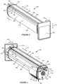
- FIGS. 2 and 3 show toner cartridge 100 according to one example embodiment.
- Toner cartridge 100 includes a body 104 housing toner reservoir 102 therein.
- Body 104 includes a top 105, a bottom 106, a front end 107, a rear end 108 and a pair of sides 109, 110.
- Body 104 has a height measured along a vertical dimension 112 of toner cartridge 100 between top 105 and bottom 106, a length measured along a longitudinal dimension 114 of toner cartridge 100 orthogonal to vertical dimension 112 between front end 107 and rear end 108, and a width measured along a side-to-side dimension 116 of toner cartridge 100 orthogonal to vertical dimension 112 and longitudinal dimension 114 between side 109 and side 110.
- each end 107, 108 of body 104 includes a respective end cap 117, 118 mounted on a corresponding end wall, such as by suitable fasteners (e.g., screws, rivets, etc.) or by a snap-fit engagement.
- end wall 119 at front end 107 and an end wall (not shown) at rear end 108 along with top 105, bottom 106 and sides 109, 110 form toner reservoir 102.
- toner cartridge 100 is inserted into image forming device 20 generally along longitudinal dimension 114 in the direction indicated by arrow A in Figures 2 and 3 with front end 107 of body 104 leading and rear end 108 of body 104 trailing.
- image forming device 20 is primarily operated, for example, accessing a user interface, media tray(s), supply item(s) (such as toner cartridge 100, developer unit 200, and PC unit 300) and other features of image forming device 20, at a side proximate to rear end 108 of body 104 of toner cartridge 100.
- Toner cartridge 100 includes an outlet port 122 for transferring toner to an inlet port of developer unit 200.
- outlet port 122 is formed as a downward facing opening on bottom 106 of body 104, next to front end 107 of body 104, such as next to an inner side of end wall 119.
- Outlet port 122 may include a shutter 123 that regulates whether toner is permitted to flow from reservoir 102 out of outlet port 122.
- Toner cartridge 100 also includes a drive coupler 124 that mates with and receives rotational power from a corresponding drive coupler in image forming device 20 when toner cartridge 100 is installed in image forming device 20 in order to provide rotational power to various rotatable components of toner cartridge 100, such as toner agitators positioned within reservoir 102 for moving toner to outlet port 122.
- drive coupler 124 is positioned on front end 107 of body 104, for example, higher than outlet port 122.
- drive coupler 124 is positioned on an outer surface of end wall 119 and exposed through an opening 126 in end cap 117 such that drive coupler 124 is unobstructed to mate with the corresponding drive coupler in image forming device 20 when toner cartridge 100 is installed in image forming device 20.
- drive coupler 124 mates with the corresponding drive coupler in image forming device 20 at an axial end portion 125 of drive coupler 124 when toner cartridge 100 is installed in image forming device 20.
- toner cartridge 100 includes a pair of guide rails 160, 162 that extend along longitudinal dimension 114 of toner cartridge 100 at top 105 of body 104.
- guide rails 160, 162 are formed as cantilevered extensions that extend outward in opposite directions along side-to-side dimension 116 of toner cartridge 100 at top 105 of body 104.
- guide rail 160 extends along side-to-side dimension 116 toward side 109 of body 104
- guide rail 162 extends along side-to-side dimension 116 toward side 110 of body 104.
- respective guide pins or posts 164, 166 project outward in opposite directions along side-to-side dimension 116 of toner cartridge 100 at a front end of each guide rail 160, 162.
- guide post 164 extends along side-to-side dimension 116 toward side 109 of body 104
- guide post 166 extends along side-to-side dimension 116 toward side 110 of body 104.
- Guide posts 164, 166 extend further outward along side-to-side dimension 116 of toner cartridge 100 than guide rails 160, 162.
- guide posts 164, 166 are positioned at end wall 119 at front end 107 of body 104.
- Each guide post 164, 166 includes a bottom contact surface 165, 167 that is positioned to contact and ride along the top surface of a corresponding guide rail that runs along the length of a guide slot that receives toner cartridge 100 in image forming device 20 during insertion of toner cartridge 100 into image forming device 20 in order to further guide insertion of toner cartridge 100 into image forming device 20 in the direction indicated by arrow A in Figures 2 and 3 .
- Contact between guide rails 160, 162 and guide posts 164, 166 of toner cartridge 100 and their corresponding guide rails in image forming device 20 may also aid in controlling the position of toner cartridge 100 along side-to-side dimension 116 and limiting rotation of toner cartridge 100 during insertion of toner cartridge 100 into image forming device 20 and removal of toner cartridge 100 from image forming device 20.
- toner cartridge 100 includes an electrical connector 130 having electrical contacts 132 that are matable with corresponding electrical contacts in image forming device 20 when toner cartridge 100 is installed in image forming device 20 for facilitating a communication link between processing circuitry 134 of toner cartridge 100 and a controller of image forming device 20. Electrical contacts 132 are electrically connected to processing circuitry 134.
- Processing circuitry 134 may provide authentication functions, safety and operational interlocks, operating parameters and/or usage information related to toner cartridge 100.
- Processing circuitry 134 may include hardware and/or software logic, as desired.
- processing circuitry 134 may include an application-specific integrated circuit (ASIC) and/or a microprocessor or the like.
- Processing circuitry 134 may also include accompanying memory, for example, non-volatile and/or volatile memory, as desired.
- electrical connector 130 and electrical contacts 132 are positioned on front end 107 of body 104. In this embodiment, electrical contacts 132 are unobstructed on front end 107 to mate with corresponding electrical contacts in image forming device 20 when toner cartridge 100 is installed in image forming device 20. In the example embodiment illustrated, electrical connector 130 and electrical contacts 132 are positioned higher than drive coupler 124, near top 105 of housing 104. In this embodiment, electrical connector 130 and electrical contacts 132 are vertically aligned with drive coupler 124 as illustrated in Figure 4 .
- electrical connector 130 includes a standard connector interface, such as, for example, a Registered Jack (RJ) connector.
- Electrical connector 130 may include a male plug end of the connector interface or a female socket, port or jack end of the connector interface with a corresponding electrical connector in image forming device 20 forming the opposite female or male end of the connector interface.
- electrical connector 130 includes a female socket 136 of an RJ45 connector.
- electrical contacts 132 are positioned within a pocket 138 of electrical connector 130 that is sized to receive the corresponding male plug end of the corresponding electrical connector in image forming device 20.
- Pocket 138 includes a forward facing opening 140 at a front end of pocket 138 that faces in the direction of insertion of toner cartridge 100 into image forming device 20, indicated by the arrow A in Figures 2 and 3 . Opening 140 permits the male plug end of the corresponding electrical connector in image forming device 20 to enter pocket 138 as toner cartridge 100 is inserted into image forming device 20 as discussed in greater detail below.
- Processing circuitry 134 is positioned on toner cartridge 100.
- processing circuitry 134 is positioned on a printed circuit board 142 mounted on housing 104 and electrically connected to electrical contacts 132.
- Printed circuit board 142 may include processing circuitry 134, which may include an ASIC and/or microprocessor and associated memory as discussed above.
- Figure 5 is an exploded view of front end 107 of housing 104 showing printed circuit board 142 according to one example embodiment.
- printed circuit board 142 is mounted on an outer surface of end wall 119, and printed circuit board 142 is attached to socket 136 with the components of printed circuit board 142 electrically connected to electrical contacts 132 positioned within pocket 138.
- electrical connector 130 including printed circuit board 142 and socket 136 having electrical contacts 132, is fixedly positioned on toner cartridge 100.
- Socket 136 is exposed through an opening 144 in end cap 117 such that pocket 138 and electrical contacts 132 therein are unobstructed in order to permit the corresponding electrical contacts in image forming device 20 to mate with electrical contacts 132 when toner cartridge 100 is installed in image forming device 20.
- processing circuitry 134 including, for example, printed circuit board 142, may be positioned in other suitable locations on toner cartridge 100, such as, for example, on top 105 or sides 109, 110 of housing 104, with processing circuitry 134 electrically connected to electrical contacts 132 such as, for example, by suitable traces, cables or wires.
- electrical connector 130 includes a custom or non-standard connector interface.
- electrical contacts 132 that mate with corresponding electrical contacts in image forming device 20 when toner cartridge 100 is installed in image forming device 20 may include electrical contacts positioned on printed circuit board 142 that are positioned to mate with corresponding electrical contacts in image forming device 20.
- toner cartridge 100 includes an alignment guide 150 that contacts the corresponding electrical connector in image forming device 20 during insertion of toner cartridge 100 into image forming device 20 in order to move the corresponding electrical connector in image forming device 20 from an unaligned position to an aligned position as discussed in greater detail below.
- the corresponding electrical connector in image forming device 20 In the unaligned position, the corresponding electrical connector in image forming device 20 is not positioned to properly mate with electrical connector 130 of toner cartridge 100.
- the aligned position the corresponding electrical connector in image forming device 20 is positioned to mate with electrical connector 130 of toner cartridge 100.
- Alignment guide 150 is positioned on front end 107 of body 104. Alignment guide 150 may be positioned at top 105 of body 104. In the example embodiment illustrated, alignment guide 150 is positioned above electrical connector 130 and electrical contacts 132. In the example embodiment illustrated, alignment guide 150 is vertically aligned with electrical connector 130 and electrical contacts 132. Alignment guide 150 extends forward, for example, in a cantilevered manner, from front end 107 of body 104 along longitudinal dimension 114 in the direction of insertion of toner cartridge 100 into image forming device 20.
- Alignment guide 150 extends further forward along longitudinal dimension 114 than electrical contacts 132 and the entrance to pocket 138 in order to contact the corresponding electrical connector in image forming device 20 prior to electrical connector 130 contacting the corresponding electrical connector in image forming device 20 during insertion of toner cartridge 100 into image forming device 20.
- alignment guide 150 forms the forward-most portion of toner cartridge 100 along longitudinal dimension 114 in the direction of insertion of toner cartridge 100 into image forming device 20. That is, in this embodiment, alignment guide 150 extends further along longitudinal dimension 114 in the direction of insertion of toner cartridge 100 into image forming device 20 than any other component of toner cartridge 100.
- alignment guide 150 includes an awning projecting along longitudinal dimension 114 from front end 107 of body 104.
- alignment guide 150 includes an upper ledge or guide member 152 having a bottom contact surface 153 positioned to contact the corresponding electrical connector in image forming device 20 during insertion of toner cartridge 100 into image forming device 20 in order to align the corresponding electrical connector in image forming device with electrical connector 130 along vertical dimension 112 as discussed in greater detail below.
- Bottom contact surface 153 faces downward, toward electrical connector 130 and electrical contacts 132.
- bottom contact surface 153 of upper guide member 152 is positioned higher than electrical connector 130 and electrical contacts 132.
- upper guide member 152 is formed as a substantially horizontal projection from front end 107 above electrical connector 130 and electrical contacts 132.
- upper guide member 152 has a substantially constant width along side-to-side dimension 116.
- bottom contact surface 153 of upper guide member 152 includes a tapered lead-in surface 153a at a front edge of bottom contact surface 153.
- alignment guide 150 includes a first side ledge or guide member 154 and may include a second side ledge or guide member 156.
- Each side guide member 154, 156 includes a respective inner side contact surface 155, 157.
- Each inner side contact surface 155, 157 faces toward an opposite side 109, 110 of body 104 along side-to-side dimension 116 with inner side contact surfaces 155, 157 facing toward each other.
- inner side contact surface 155 of side guide member 154 is positioned closer to side 110 of body 104 than to side 109 of body 104
- inner side contact surface 157 of side guide member 156 is positioned closer to side 109 of body 104 than to side 110 of body 104.
- inner side contact surface 155 of side guide member 154 is positioned closer to side 110 of body 104 than electrical connector 130 and electrical contacts 132 are to side 110 of body 104
- inner side contact surface 157 of side guide member 156 is positioned closer to side 109 of body 104 than electrical connector 130 and electrical contacts 132 are to side 109 of body 104.
- Inner side contact surface 155 of side guide member 154 is positioned to contact the corresponding electrical connector in image forming device 20 during insertion of toner cartridge 100 into image forming device 20 in order to align the corresponding electrical connector in image forming device with electrical connector 130 along side-to-side dimension 116 as discussed in greater detail below.
- side guide member 156 provides symmetry and structural support for upper guide member 152.
- Inner side contact surface 157 of side guide member 156 may also help prevent overtravel of the corresponding electrical connector in image forming device 20 during mating with electrical connector 130 as discussed in greater detail below.
- each side guide member 154, 156 is formed as a substantially vertical projection from front end 107 that extends downward from upper guide member 152.
- each side guide member 154, 156 has a substantially constant height along vertical dimension 112.
- each inner side contact surface 155, 157 includes a tapered lead-in surface 155a, 157a at a front edge of the inner side contact surface 155, 157.
- alignment guide 150 is formed integrally with end cap 117.
- forming alignment guide 150 integrally with end cap 117 helps reduce tolerance stackup between alignment guide 150 and electrical connector 130, which is mounted to end wall 119 in the example embodiment illustrated.
- alignment guide 150 may be formed integrally with end wall 119, or as one or more components attachable to body 104, such as to end cap 117 and/or end wall 119.
- upper guide member 152 and side guide members 154, 156 consist of a single, unitary component. However, in other embodiments, upper guide member 152 and side guide members 154, 156 may each include one or more separate and distinct elements.
- Figures 6-9 show an electrical connector 400 of image forming device 20 that is matable with electrical connector 130 of toner cartridge 100 when toner cartridge 100 is installed in image forming device 20 according to one example embodiment.
- Electrical connector 400 includes electrical contacts 402 that are electrically connected to a controller of image forming device 20. Electrical contacts 402 mate with electrical contacts 132 of toner cartridge 100 when toner cartridge 100 is installed in image forming device 20 in order to facilitate a communication link between processing circuitry 134 of toner cartridge 100 and a controller of image forming device 20.
- electrical connector 400 of image forming device 20 may include a standard connector interface, such as, for example, a Registered Jack (RJ) connector, or a custom or non-standard connector interface, as desired.
- RJ Registered Jack
- Electrical connector 400 may include a male plug end of the connector interface or a female socket, port or jack end of the connector interface with electrical connector 130 of toner cartridge 100 forming the opposite female or male end of the connector interface.
- electrical connector 400 includes a male plug 404 of an RJ45 connector. Electrical contacts 402 are positioned on plug 404 to mate with corresponding electrical contacts 132 of toner cartridge 100 when plug 404 mates with socket 136 of electrical connector 130 of toner cartridge 100.
- electrical connector 400 includes a housing 406.
- plug 404 including electrical contacts 402
- housing 406 is fixedly mounted to housing 406, such as, for example, by a snap-fit engagement.
- Housing 406 is mounted to a bracket 408 that is fixedly attached to a frame 410 of image forming device 20.
- Housing 406 includes a top 412, a bottom 413, a first side 414, a second side 415, a front end 416 that faces toward toner cartridge 100 when toner cartridge 100 is installed in image forming device 20, and a rear end 417 that faces away from toner cartridge 100 when toner cartridge 100 is installed in image forming device 20.
- Electrical connector 400 including electrical contacts 402, plug 404 and housing 406, is movable relative to bracket 408 and frame 410.
- electrical connector 400 is pivotable upward and downward, as indicated by the arrows in Figure 8 , relative to bracket 408 and frame 410 about a pivot axis 420.
- housing 406 includes a pair of guide posts 422, 423 that extend from opposite sides 414, 415 of housing 406. Guide posts 422, 423 are closely received by corresponding guide slots 424, 425 of bracket 408 to define pivot axis 420.
- pivot axis 420 is substantially parallel to side-to-side dimension 116 of toner cartridge 100 when toner cartridge 100 is installed in image forming device 20.
- housing 406 also includes a guide post 426 that extends from side 414 of housing 406, parallel to guide posts 422, 423. Guide post 426 is received by an elongated slot 428 of bracket 408. The engagement between guide post 426 of housing 406 and elongated slot 428 of bracket 408 limits the range of pivoting motion of housing 406 relative to bracket 408 about pivot axis 420.
- each guide post 422, 423 includes a distal portion 422a, 423a having a diameter that is small enough to enter corresponding guide slots 424, 425 and a proximal portion 422b, 423b having a diameter that is too large to enter corresponding guide slots 424, 425.
- the engagement between proximal portions 422b, 423b of guide posts 422, 423 of housing 406 and side surfaces 430, 431 of bracket 408 surrounding guide slots 424, 425 defines the range of translating motion of housing 406 relative to bracket 408.
- guide post 426 of housing 406 is sized relative to elongated guide slot 428 of bracket 408 such that the engagement between guide post 426 and elongated guide slot 428 does not impede the translating motion of housing 406 relative to bracket 408 in a direction parallel to pivot axis 420.
- guide post 426 and elongated guide slot 428 may be sized to limit, at least in part, the range of translating motion of housing 406 relative to bracket 408.
- electrical connector 400 translatable relative to bracket 408 and frame 410 in a direction parallel to pivot axis 420 and side-to-side dimension 116 of toner cartridge 100
- electrical connector 400 is pivotable relative to bracket 408 and frame 410, toward and away from side surfaces 430, 431 of bracket 408, such as about a vertical pivot axis.
- electrical connector 400 is biased relative to bracket 408 and frame 410 toward an unaligned position wherein electrical connector 400 is not aligned to mate with electrical connector 130 of toner cartridge 100.
- alignment guide 150 of toner cartridge 100 contacts housing 406 and moves electrical connector 400 from the unaligned position to an aligned position of electrical connector 400 to properly align and mate with electrical connector 130 of toner cartridge 100 as discussed in greater detail below.
- Figures 6-9 show electrical connector 400 in the unaligned position, its home position as a result of the bias applied to electrical connector 400.
- electrical connector 400 is biased relative to bracket 408 and frame 410 toward the unaligned position by an extension spring 432.
- a first end 432a of spring 432 is attached to a spring mount 434 positioned at top 412 and side 415 of housing 406, and a second end 432b of spring 432 is attached to a spring mount 435 positioned on side surface 430 of bracket 408.
- spring mount 434 on housing 406 is positioned closer to front end 416 of housing 406 than spring mount 435 on bracket 408 is to front end 416 of housing 406.
- ends 432a, 432b of spring 432 and spring mounts 434, 435 also results in an upward bias force about pivot axis 420 such that housing 406 is biased upward relative to bracket 408.
- guide post 426 is positioned against an upper surface of elongated guide slot 428 of bracket 408 when electrical connector 400 is in its home position.
- electrical connector 400 may be biased relative to bracket 408 by any suitable biasing member as desired, including, for example, one or more compression springs, torsion springs, leaf springs, or other materials having resilient properties.
- a side surface 438 of lead-in 436 also tapers inward sideways in a direction from side 414 of housing 406 toward side 415 of housing 406 as it extends forward in a direction from rear end 417 of housing 406 toward front end 416 of housing 406 to further help electrical connector 400 mate with electrical connector 130 of toner cartridge 100 and move from the unaligned position to the aligned position during insertion of toner cartridge 100 into image forming device 20.
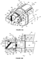
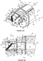
- Figures 13A-13C show toner cartridge 100 advanced forward in the direction of insertion of toner cartridge 100 from the position shown in Figures 12A-12C toward electrical connector 400.
- Figures 13A and 13B show housing 406 of electrical connector 400 shifted further along pivot axis 420 and side-to-side dimension 116 of toner cartridge 100 from the position shown in Figures 12A and 12B in the direction indicated by arrow 501 as a result of the contact between inner side contact surface 153 of side guide member 154 of alignment guide 150 of toner cartridge 100 and lead-in 436 on side 414 of housing 406 of electrical connector 400.
- Plug 404 and electrical contacts 402 of electrical connector 400 are aligned with socket 136 and electrical contacts 132 of electrical connector 130 of toner cartridge 100 rotationally about pivot axis 420 and along vertical dimension 112 of toner cartridge 100, and this alignment is maintained by contact between bottom contact surface 153 of upper guide member 152 of alignment guide 150 of toner cartridge 100 and top 412 of housing 406 of electrical connector 400.
- Figures 14A-14C show toner cartridge 100 in its final installed position in image forming device 20, advanced forward in the direction of insertion of toner cartridge 100 from the position shown in Figures 13A-13C .
- contact between alignment guide 150 of toner cartridge 100 and housing 406 of electrical connector 400 maintains electrical connector 400 in the aligned position relative to toner cartridge 100 allowing plug 404 of electrical connector 400 to mate with socket 136 of electrical connector 130 of toner cartridge 100 such that electrical contacts 402 of electrical connector 400 contact electrical contacts 132 of electrical connector 130 of toner cartridge 100 in order to establish a communication link between processing circuitry 134 of toner cartridge 100 and a controller of image forming device 20.
- alignment guide 150 of toner cartridge 100 controls the position of electrical connector 400, including electrical contacts 402, as toner cartridge 100 nears electrical connector 400 during insertion of toner cartridge 100 into image forming device 20.
- the biasing and locating of housing 406 of electrical connector 400 against bottom contact surface 153 of upper guide member 152 and inner side contact surface 155 of side guide member 154 of alignment guide 150 helps reduce tolerance stackup between electrical connector 400 and electrical connector 130 in order to ensure that electrical connector 130 of toner cartridge 100 mates accurately and reliably with electrical connector 400 and that a consistent electrical connection is maintained between electrical contacts 402 and electrical contacts 132.
- toner cartridge 100 when toner cartridge 100 is fully inserted into image forming device 20, in its final installed position in image forming device 20, engagement between plug 404 of electrical connector 400 and socket 136 of electrical connector 130 of toner cartridge 100 controls the position of electrical contacts 402 of electrical connector 400 relative to electrical contacts 132 of electrical connector 130 of toner cartridge 100 along vertical dimension 112 and side-to-side dimension 116 of toner cartridge 100.
- alignment guide 150 of toner cartridge 100 provides initial alignment of electrical connector 400 of image forming device 20 with electrical connector 130 of toner cartridge 100 during insertion of toner cartridge 100 into image forming device 20, and the engagement between plug 404 of electrical connector 400 and socket 136 of electrical connector 130 of toner cartridge 100 provides fine alignment of electrical connector 400 of image forming device 20 with electrical connector 130 of toner cartridge 100 as toner cartridge 100 reaches its final installed position in image forming device 20.
- the position of electrical contacts 402 of electrical connector 400 relative to electrical contacts 132 of electrical connector 130 of toner cartridge 100 along longitudinal dimension 114 of toner cartridge 100 is controlled by the final position of toner cartridge 100 in image forming device 20 along longitudinal dimension 114.
- one or more positioning features on an exterior of toner cartridge 100 may contact corresponding datums in image forming device 20 to control the position of toner cartridge 100 in image forming device 20 along longitudinal dimension 114.
- toner cartridge 100 When toner cartridge 100 is removed from image forming device 20, this sequence is reversed. Electrical connector 130 of toner cartridge 100 separates from electrical connector 400 of image forming device 20, and electrical connector 400 returns to the home position shown in Figures 6-9 as a result of the bias force applied by spring 432 as housing 406 of electrical connector 400 separates from alignment guide 150 of toner cartridge 100.
- While the example embodiment illustrated includes housing 406 of electrical connector 400 biased toward side surface 430 of bracket 408 and away from side surface 431 of bracket 408 and side contact surface 155 of side guide member 154 of alignment guide 150 of toner cartridge 100 aligning electrical connector 400 along side-to-side dimension 116 of toner cartridge 100, this configuration may be reversed as desired such that housing 406 of electrical connector 400 biased toward side surface 431 of bracket 408 and away from side surface 430 of bracket 408 and side contact surface 157 of side guide member 156 of alignment guide 150 of toner cartridge 100 aligns electrical connector 400 along side-to-side dimension 116 of toner cartridge 100.
- alignment guide 150 of toner cartridge 100 that includes an upper guide member 152 that aligns plug 404 and electrical contacts 402 of electrical connector 400 with socket 136 and electrical contacts 132 of electrical connector 130 of toner cartridge 100 in vertical dimension 112 of toner cartridge 100 and a side guide member 154 that aligns plug 404 and electrical contacts 402 of electrical connector 400 with socket 136 and electrical contacts 132 of electrical connector 130 of toner cartridge 100 in side-to-side dimension 116 of toner cartridge 100
- alignment guide 150 may include a first guide member and a second guide member that align electrical connector 400 of image forming device 20 with electrical contacts 132 of electrical connector 130 of toner cartridge 100 in any two dimensions or directions during insertion of toner cartridge 100 into image forming device 20.
- an electrical connector such as electrical connector 130
- an electrical connector having positioning features like alignment guide 150 may be used on any replaceable unit of image forming device 20, such as, for example, developer unit 200 and/or PC unit 300 in order to establish communication between a controller of image forming device 20 and processing circuitry of the replaceable unit.
- the replaceable unit(s) of image forming device 20 may employ any suitable configuration as desired.
- the main toner supply for image forming device 20, developer unit 200 and PC unit 300 are combined in a separate replaceable unit for each color toner.
- the main toner supply for image forming device 20 and developer unit 200 are provided in a first replaceable unit and PC unit 300 is provided in a second replaceable unit.
- Other combinations are possible without departing from the scope of the present disclosure.
- the example image forming device 20 discussed above includes four toner cartridges 100 and corresponding developer units 200 and PC units 300, more or fewer replaceable units may be used depending on the color options needed.
- the image forming device includes a single toner cartridge and corresponding developer unit and PC unit in order to permit monochrome printing.
Landscapes
- Physics & Mathematics (AREA)
- General Physics & Mathematics (AREA)
- Electrophotography Configuration And Component (AREA)
- Details Of Connecting Devices For Male And Female Coupling (AREA)
Abstract
Description
- The present disclosure relates generally to image forming devices and more particularly to a toner container having positioning features for electrical contacts.
- During the electrophotographic printing process, an electrically charged rotating photoconductive drum is selectively exposed to a laser beam. The areas of the photoconductive drum exposed to the laser beam are discharged, creating an electrostatic latent image of a page to be printed on the photoconductive drum. Toner particles are then electrostatically picked up by the latent image on the photoconductive drum, creating a toned image on the drum. The toned image is transferred to the print media (e.g., paper) either directly by the photoconductive drum or indirectly by an intermediate transfer member. The toner is then fused to the media using heat and pressure to complete the print.
- The image forming device's toner supply is typically stored in one or more replaceable units having a shorter lifespan than the image forming device. It is desired to communicate various operating parameters and usage information of the replaceable unit(s) to the image forming device for proper operation. For example, it may be desired to communicate such information as replaceable unit serial number, replaceable unit type, toner color, toner capacity, amount of toner remaining, license information, authentication information, etc. The replaceable unit(s) typically include processing circuitry configured to communicate with and respond to commands from a controller in the image forming device. The replaceable unit(s) also include memory associated with the processing circuitry that stores, for example, program instructions and information related to the replaceable unit. The processing circuitry and associated memory are typically mounted on a circuit board attached to the replaceable unit. The replaceable unit also includes one or more electrical contacts that mate with corresponding electrical contacts in the image forming device upon installation of the replaceable unit in the image forming device in order to facilitate communication between the processing circuitry of the replaceable unit and the controller of the image forming device. It is important to accurately position the electrical contacts of the replaceable unit relative to the corresponding electrical contacts of the image forming device in order to ensure a reliable connection between the processing circuitry of the replaceable unit and the controller of the image forming device when the replaceable unit is installed in the image forming device.
- A toner container for use in an image forming device according to one example embodiment includes a body having a top, a bottom, a first side and a second side positioned between a first end and a second end of the body. The first end of the body leads during insertion of the toner container into the image forming device, and the second end trails during insertion of the toner container into the image forming device. The body has a reservoir for holding toner. A drive coupler is positioned on the first end of the body for mating with a corresponding drive coupler in the image forming device when the toner container is installed in the image forming device for receiving rotational motion from the corresponding drive coupler in the image forming device. An electrical contact is positioned on the first end of the body for contacting a corresponding electrical contact in the image forming device when the toner container is installed in the image forming device. The electrical contact of the toner container is positioned higher than the drive coupler of the toner container. An alignment guide is positioned on the first end of the body. The alignment guide includes an upper guide having a bottom contact surface for contacting an electrical connector of the image forming device that includes the corresponding electrical contact of the image forming device during insertion of the toner container into the image forming device to move the electrical connector of the image forming device downward relative to the toner container during insertion of the toner container into the image forming device with the first end of the body leading. The alignment guide includes a side guide having an inner side contact surface for contacting the electrical connector of the image forming device during insertion of the toner container into the image forming device to move the electrical connector of the image forming device relative to the toner container in a direction away from the first side of the body and toward the second side of the body during insertion of the toner container into the image forming device with the first end of the body leading. The bottom contact surface of the upper guide is positioned higher than the electrical contact of the toner container. The inner side contact surface of the side guide is positioned lower than the bottom contact surface of the upper guide and closer to the first side of the body than the electrical contact of the toner container is to the first side of the body.
- Embodiments include those wherein the electrical contact of the toner container is aligned with the drive coupler of the toner container along a vertical dimension of the toner container. In some embodiments, the upper guide is aligned with the electrical contact of the toner container along the vertical dimension of the toner container.
- Embodiments include those wherein the first end of the body includes an end cap mounted to an end wall of the body, and the alignment guide is formed integrally with the end cap.
- Embodiments include those wherein the upper guide includes a horizontal projection from the first end of the body above the electrical contact of the toner container. In some embodiments, the side guide includes a vertical projection from the first end of the body.
- Embodiments include those wherein the inner side contact surface of the side guide is positioned closer to the first side of the body than to the second side of the body.
- In some embodiments, the side guide extends downward from the upper guide.
- Embodiments include those wherein the alignment guide extends further in a direction from the second end of the body toward the first end of the body than the electrical contact of the toner container.
- In some embodiments, the alignment guide forms a leading edge of the toner container in a direction from the second end of the body toward the first end of the body.
- Embodiments include those wherein the electrical contact of the toner container is electrically connected to processing circuitry positioned on the toner container.
- A toner container for use in an image forming device according to another example embodiment includes a body having a top, a bottom, a first side and a second side positioned between a first longitudinal end and a second longitudinal end of the body. The first longitudinal end of the body leads during insertion of the toner container into the image forming device, and the second longitudinal end trails during insertion of the toner container into the image forming device. A longitudinal dimension of the toner container that is orthogonal to a vertical dimension of the toner container extends between the first longitudinal end of the body and the second longitudinal end of the body. A side-to-side dimension of the toner container that is orthogonal to the longitudinal dimension of the toner container and the vertical dimension of the toner container extends between the first side of the body and the second side of the body. The body has a reservoir for holding toner. An outlet port is positioned on the bottom of the body and adjacent to the first longitudinal end of the body for exiting toner from the toner container. A drive coupler is positioned on the first longitudinal end of the body for mating with a corresponding drive coupler in the image forming device when the toner container is installed in the image forming device for receiving rotational motion from the corresponding drive coupler in the image forming device. The drive coupler of the toner container is positioned higher in the vertical dimension of the toner container than the outlet port. An electrical contact is positioned on the first longitudinal end of the body for contacting a corresponding electrical contact in the image forming device when the toner container is installed in the image forming device. The electrical contact of the toner container is electrically connected to processing circuitry positioned on the toner container. The electrical contact of the toner container is positioned higher in the vertical dimension of the toner container than the drive coupler of the toner container. An alignment guide is positioned on the first longitudinal end of the body. The alignment guide includes an upper guide having a bottom contact surface that is unobstructed to contact an electrical connector of the image forming device that includes the corresponding electrical contact of the image forming device during insertion of the toner container into the image forming device for moving the electrical connector of the image forming device downward relative to the toner container during insertion of the toner container into the image forming device with the first longitudinal end of the body leading in order to align the electrical connector of the image forming device with the electrical contact of the toner container in the vertical dimension of the toner container. The alignment guide includes a side guide having an inner side contact surface that is unobstructed to contact the electrical connector of the image forming device during insertion of the toner container into the image forming device for moving the electrical connector of the image forming device relative to the toner container along the side-to-side dimension of the toner container in a direction away from the first side of the body and toward the second side of the body during insertion of the toner container into the image forming device with the first longitudinal end of the body leading in order to align the electrical connector of the image forming device with the electrical contact of the toner container in the side-to-side dimension of the toner container. The bottom contact surface of the upper guide is positioned higher in the vertical dimension of the toner container than the electrical contact of the toner container and the inner side contact surface of the side guide. The inner side contact surface of the side guide is spaced along the side-to-side dimension of the toner container toward the first side of the body from the electrical contact of the toner container.
- Embodiments include those wherein the first longitudinal end of the body includes an end cap mounted to an end wall of the body, and the alignment guide is formed integrally with the end cap.
- Embodiments include those wherein the upper guide includes a horizontal projection from the first longitudinal end of the body above the electrical contact of the toner container.
- Embodiments include those wherein the side guide includes a vertical projection from the first longitudinal end of the body.
- Embodiments include those wherein the inner side contact surface of the side guide is positioned closer to the first side of the body than to the second side of the body.
- Embodiments include those wherein the side guide extends downward from the upper guide.
- Embodiments include those wherein the alignment guide extends further along the longitudinal dimension of the toner container in a direction from the second longitudinal end of the body toward the first longitudinal end of the body than the electrical contact of the toner container.
- Embodiments include those wherein the alignment guide forms a forward-most portion of the toner container along the longitudinal dimension of the toner container in a direction from the second longitudinal end of the body toward the first longitudinal end of the body.
- A toner container for use in an image forming device according to another example embodiment includes a body having a top, a bottom, a first side and a second side positioned between a first longitudinal end and a second longitudinal end of the body. The first longitudinal end of the body leads during insertion of the toner container into the image forming device, and the second longitudinal end trails during insertion of the toner container into the image forming device. A longitudinal dimension of the toner container extends between the first longitudinal end of the body and the second longitudinal end of the body. The body has a reservoir for holding toner. A drive coupler is positioned on the first longitudinal end of the body for mating with a corresponding drive coupler in the image forming device when the toner container is installed in the image forming device for receiving rotational motion from the corresponding drive coupler in the image forming device. An electrical contact is positioned on the first longitudinal end of the body for contacting a corresponding electrical contact in the image forming device when the toner container is installed in the image forming device. An alignment guide is positioned on the first longitudinal end of the body. The alignment guide includes a first guide having a first contact surface for contacting an electrical connector of the image forming device that includes the corresponding electrical contact of the image forming device during insertion of the toner container into the image forming device to move the electrical connector of the image forming device in a first direction relative to the toner container during insertion of the toner container into the image forming device to align the electrical connector of the image forming device with the electrical contact of the toner container in a first dimension of the toner container that is orthogonal to the longitudinal dimension of the toner container. The alignment guide includes a second guide having a second contact surface for contacting the electrical connector of the image forming device during insertion of the toner container into the image forming device to move the electrical connector of the image forming device in a second direction relative to the toner container during insertion of the toner container into the image forming device to align the electrical connector of the image forming device with the electrical contact of the toner container in a second dimension of the toner container that is orthogonal to the longitudinal dimension of the toner container and the first dimension of the toner container. The alignment guide forms a leading edge of the toner container along the longitudinal dimension of the toner container in a direction from the second longitudinal end of the body toward the first longitudinal end of the body.
- Embodiments include those wherein the first contact surface includes a bottom contact surface of the first guide for contacting the electrical connector of the image forming device during insertion of the toner container into the image forming device to move the electrical connector of the image forming device downward relative to the toner container during insertion of the toner container into the image forming device to align the electrical connector of the image forming device with the electrical contact of the toner container in a vertical dimension of the toner container that is orthogonal to the longitudinal dimension of the toner container, and the second contact surface includes a side contact surface for contacting the electrical connector of the image forming device during insertion of the toner container into the image forming device to move the electrical connector of the image forming device in the second direction relative to the toner container during insertion of the toner container into the image forming device to align the electrical connector of the image forming device with the electrical contact of the toner container in a side-to-side dimension of the toner container that is orthogonal to the longitudinal dimension of the toner container and the vertical dimension of the toner container.
- Embodiments include those wherein the bottom contact surface of the first guide is positioned higher than the side contact surface of the second guide.
- Embodiments include those wherein the bottom contact surface of the first guide is positioned higher than the electrical contact of the toner container.
- Embodiments include those wherein the electrical contact of the toner container is positioned higher than the drive coupler of the toner container.
- Embodiments include those wherein the first longitudinal end of the body includes an end cap mounted to an end wall of the body, and the alignment guide is formed integrally with the end cap.
- Embodiments include those wherein the second guide extends orthogonally from the first guide.
- Embodiments include those wherein the electrical contact of the toner container is electrically connected to processing circuitry positioned on the toner container.
- The accompanying drawings incorporated in and forming a part of the specification, illustrate several aspects of the present disclosure, and together with the description serve to explain the principles of the present disclosure.
-
Figure 1 is a schematic view of an image forming device according to one example embodiment. -
Figures 2-4 are perspective views of a toner cartridge according to one example embodiment. -
Figure 5 is an exploded view of the toner cartridge shown inFigures 2-4 . -
Figure 6 is a perspective view of an electrical connector of the image forming device mounted to a frame of the image forming device according to one example embodiment. -
Figures 7 and8 are perspective views of the electrical connector of the image forming device shown inFigure 6 showing a housing of the electrical connector in a home position relative to a bracket according to one example embodiment. -
Figure 9 is a top plan view of the electrical connector of the image forming device shown inFigures 6-8 showing a housing of the electrical connector in the home position relative to the bracket according to one example embodiment. -
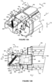
Figures 10A ,11A ,12A ,13A and14A are sequential perspective views showing the mating of an electrical connector of the toner cartridge with the electrical connector of the image forming device during insertion of the toner cartridge into the image forming device according to one example embodiment. -
Figures 10B ,11B ,12B ,13B and14B are sequential top plan views in positions corresponding toFigures 10A ,11A ,12A ,13A and14A , respectively, showing the mating of the electrical connector of the toner cartridge with the electrical connector of the image forming device during insertion of the toner cartridge into the image forming device according to one example embodiment. -
Figures 10C, 11C, 12C ,13C and 14C are sequential cross-sectional views in positions corresponding toFigures 10A ,11A ,12A ,13A and14A , respectively, showing the mating of the electrical connector of the toner cartridge with the electrical connector of the image forming device during insertion of the toner cartridge into the image forming device according to one example embodiment. - In the following description, reference is made to the accompanying drawings where like numerals represent like elements. The embodiments are described in sufficient detail to enable those skilled in the art to practice the present disclosure. It is to be understood that other embodiments may be utilized and that process, electrical, and mechanical changes, etc., may be made without departing from the scope of the present disclosure. Examples merely typify possible variations. Portions and features of some embodiments may be included in or substituted for those of others. The following description, therefore, is not to be taken in a limiting sense, and the scope of the present disclosure is defined only by the appended claims and their equivalents.
-
Figure 1 illustrates a schematic view of the interior of an exampleimage forming device 20.Image forming device 20 includes ahousing 22.Housing 22 includes one ormore input trays 28 positioned therein. Eachtray 28 is sized to contain a stack of media sheets. As used herein, the term media is meant to encompass not only paper but also labels, envelopes, fabrics, photographic paper and any other desired substrate.Trays 28 are preferably removable for refilling. A control panel may be located onhousing 22. Using the control panel, a user is able to enter commands and generally control the operation ofimage forming device 20. For example, a user may enter commands to switch modes (e.g., color mode, monochrome mode), view the number of images printed, etc. Amedia path 32 extends throughimage forming device 20 for moving the media sheets through the image transfer process.Media path 32 includes asimplex path 34 and may include aduplex path 36. A media sheet is introduced intosimplex path 34 fromtray 28 by apick mechanism 38. In the example embodiment shown, pickmechanism 38 includes a roll positioned to move the media sheet fromtray 28 and intomedia path 32. The media sheet is then moved alongmedia path 32 by various transport rollers. Media sheets may also be introduced intomedia path 32 by amanual feed 46 having one or more rolls 48. -
Image forming device 20 includes an image transfer section that includes one ormore imaging stations 50. Eachimaging station 50 includes atoner cartridge 100, a developer unit 200 and a photoconductive unit (PC unit) 300. Eachtoner cartridge 100 includes areservoir 102 for holding toner and an outlet port in communication with an inlet port of a corresponding developer unit 200 for transferring toner fromreservoir 102 to developer unit 200 as discussed in greater detail below. In the example embodiment illustrated, developer unit 200 utilizes what is commonly referred to as a single component development system. In this embodiment, each developer unit 200 includes atoner reservoir 202 and atoner adder roll 204 that moves toner fromreservoir 202 to adeveloper roll 206. In another embodiment, developer unit 200 utilizes what is commonly referred to as a dual component development system. In this embodiment, toner intoner reservoir 202 is mixed with magnetic carrier beads. The magnetic carrier beads may be coated with a polymeric film to provide triboelectric properties to attract toner to the carrier beads as the toner and the magnetic carrier beads are mixed in the toner reservoir. In this embodiment,developer roll 206 attracts the magnetic carrier beads having toner thereon todeveloper roll 206 through the use of magnetic fields. EachPC unit 300 includes a chargingroll 304 and a photoconductive (PC)drum 302 for eachimaging station 50. PC drums 302 are mounted substantially parallel to each other. For purposes of clarity, developer unit 200 andPC unit 300 are labeled on only one of theimaging stations 50 inFigure 1 . In the example embodiment illustrated, eachimaging station 50 is substantially the same except for the color of toner contained therein. - Each charging
roll 304 forms a nip with thecorresponding PC drum 302. During a print operation, chargingroll 304 charges the surface ofPC drum 302 to a specified voltage. A laser beam from aprinthead 52 associated with eachimaging station 50 is then directed to the surface ofPC drum 302 and selectively discharges those areas it contacts to form a latent image.Developer roll 206 then transfers toner toPC drum 302 to form a toner image. A metering device, such as adoctor blade 208, may be used to meter toner ondeveloper roll 206 and apply a desired charge to the toner prior to its transfer toPC drum 302. Toner is attracted to the areas ofPC drum 302 surface discharged by the laser beam fromprinthead 52. - In the example embodiment illustrated, an intermediate transfer mechanism (ITM) 54 is disposed adjacent to
imaging stations 50. In this embodiment,ITM 54 is formed as an endless belt trained about adrive roll 56, atension roll 58 and a back-up roll 60. During print operations,ITM 54 moves pastimaging stations 50 in a counterclockwise direction as viewed inFigure 1 . One or more ofPC drums 302 apply toner images in their respective colors toITM 54 at a first transfer nip 62.ITM 54 rotates and collects the one or more toner images fromimaging stations 50 and then conveys the toner images to a media sheet advancing throughsimplex path 34 at a second transfer nip 64 formed between atransfer roll 66 andITM 54, which is supported by back-up roll 60. In other embodiments, the toner image is transferred to the media sheet directly by the PC drum(s) 302. - The media sheet with the toner image is then moved along the
media path 32 and into afuser area 68.Fuser area 68 includes fusing rolls orbelts 70 that form a nip 72 to adhere the toner image to the media sheet. The fused media sheet then passes through transport rolls 74 located downstream fromfuser area 68, which move the media sheet to anoutput area 76 ofimage forming device 20 or toduplex path 36 for image formation on a second side of the media sheet, as desired. - A monocolor
image forming device 20 may include asingle imaging station 50, as compared to a colorimage forming device 20 that may includemultiple imaging stations 50. -
Figures 2 and 3 show toner cartridge 100 according to one example embodiment.Toner cartridge 100 includes abody 104housing toner reservoir 102 therein.Body 104 includes a top 105, a bottom 106, afront end 107, arear end 108 and a pair ofsides Body 104 has a height measured along avertical dimension 112 oftoner cartridge 100 between top 105 and bottom 106, a length measured along alongitudinal dimension 114 oftoner cartridge 100 orthogonal tovertical dimension 112 betweenfront end 107 andrear end 108, and a width measured along a side-to-side dimension 116 oftoner cartridge 100 orthogonal tovertical dimension 112 andlongitudinal dimension 114 betweenside 109 andside 110. In the example embodiment illustrated, eachend body 104 includes arespective end cap end wall 119 atfront end 107 and an end wall (not shown) atrear end 108 along with top 105, bottom 106 andsides form toner reservoir 102. In the example embodiment illustrated,toner cartridge 100 is inserted intoimage forming device 20 generally alonglongitudinal dimension 114 in the direction indicated by arrow A inFigures 2 and 3 withfront end 107 ofbody 104 leading andrear end 108 ofbody 104 trailing. - As used herein, the terms "front" and "rear" correspond to the direction of travel of
toner cartridge 100 during insertion oftoner cartridge 100 intoimage forming device 20 rather than any particular orientation ofimage forming device 20. For example, in one embodiment,image forming device 20 is primarily operated, for example, accessing a user interface, media tray(s), supply item(s) (such astoner cartridge 100, developer unit 200, and PC unit 300) and other features ofimage forming device 20, at a side proximate torear end 108 ofbody 104 oftoner cartridge 100. -
Toner cartridge 100 includes anoutlet port 122 for transferring toner to an inlet port of developer unit 200. In the example embodiment illustrated,outlet port 122 is formed as a downward facing opening onbottom 106 ofbody 104, next tofront end 107 ofbody 104, such as next to an inner side ofend wall 119.Outlet port 122 may include ashutter 123 that regulates whether toner is permitted to flow fromreservoir 102 out ofoutlet port 122. -
Toner cartridge 100 also includes adrive coupler 124 that mates with and receives rotational power from a corresponding drive coupler inimage forming device 20 whentoner cartridge 100 is installed inimage forming device 20 in order to provide rotational power to various rotatable components oftoner cartridge 100, such as toner agitators positioned withinreservoir 102 for moving toner tooutlet port 122. In the example embodiment illustrated,drive coupler 124 is positioned onfront end 107 ofbody 104, for example, higher thanoutlet port 122. In the embodiment illustrated,drive coupler 124 is positioned on an outer surface ofend wall 119 and exposed through anopening 126 inend cap 117 such that drivecoupler 124 is unobstructed to mate with the corresponding drive coupler inimage forming device 20 whentoner cartridge 100 is installed inimage forming device 20. In the embodiment illustrated,drive coupler 124 mates with the corresponding drive coupler inimage forming device 20 at anaxial end portion 125 ofdrive coupler 124 whentoner cartridge 100 is installed inimage forming device 20. - In the example embodiment illustrated,
toner cartridge 100 includes a pair ofguide rails longitudinal dimension 114 oftoner cartridge 100 attop 105 ofbody 104. In this embodiment,guide rails side dimension 116 oftoner cartridge 100 attop 105 ofbody 104. Specifically,guide rail 160 extends along side-to-side dimension 116 towardside 109 ofbody 104, andguide rail 162 extends along side-to-side dimension 116 towardside 110 ofbody 104. Eachguide rail bottom contact surface toner cartridge 100 to image formingdevice 20 during insertion oftoner cartridge 100 intoimage forming device 20 in order to guide insertion oftoner cartridge 100 intoimage forming device 20 in the direction indicated by arrow A inFigures 2 and 3 withfront end 107 ofbody 104 leading andrear end 108 ofbody 104 trailing. In the example embodiment illustrated,guide rails body 104 oftoner cartridge 100 alonglongitudinal dimension 114 oftoner cartridge 100, fromend wall 119 atfront end 107 ofbody 104 to an inner end ofend cap 118 atrear end 108 ofbody 104. - In the example embodiment illustrated, respective guide pins or
posts side dimension 116 oftoner cartridge 100 at a front end of eachguide rail post 164 extends along side-to-side dimension 116 towardside 109 ofbody 104, and guidepost 166 extends along side-to-side dimension 116 towardside 110 ofbody 104. Guide posts 164, 166 extend further outward along side-to-side dimension 116 oftoner cartridge 100 thanguide rails end wall 119 atfront end 107 ofbody 104. Eachguide post bottom contact surface toner cartridge 100 inimage forming device 20 during insertion oftoner cartridge 100 intoimage forming device 20 in order to further guide insertion oftoner cartridge 100 intoimage forming device 20 in the direction indicated by arrow A inFigures 2 and 3 . - Contact between bottom contact surfaces 161, 163 of
guide rails toner cartridge 100 and the top surfaces of corresponding guide rails positioned at an entrance to image formingdevice 20 and between bottom contact surfaces 165, 167 ofguide posts toner cartridge 100 and the top surfaces of corresponding guide rails that run along the length of a guide slot that receivestoner cartridge 100 inimage forming device 20 controls the position oftoner cartridge 100 alongvertical dimension 112 during insertion oftoner cartridge 100 intoimage forming device 20 and removal oftoner cartridge 100 fromimage forming device 20 and may aid inpositioning toner cartridge 100 alongvertical dimension 112 whentoner cartridge 100 is in its final installed position inimage forming device 20. Contact betweenguide rails posts toner cartridge 100 and their corresponding guide rails inimage forming device 20 may also aid in controlling the position oftoner cartridge 100 along side-to-side dimension 116 and limiting rotation oftoner cartridge 100 during insertion oftoner cartridge 100 intoimage forming device 20 and removal oftoner cartridge 100 fromimage forming device 20. - With reference to
Figures 2-5 ,toner cartridge 100 includes anelectrical connector 130 havingelectrical contacts 132 that are matable with corresponding electrical contacts inimage forming device 20 whentoner cartridge 100 is installed inimage forming device 20 for facilitating a communication link betweenprocessing circuitry 134 oftoner cartridge 100 and a controller ofimage forming device 20.Electrical contacts 132 are electrically connected to processingcircuitry 134.Processing circuitry 134 may provide authentication functions, safety and operational interlocks, operating parameters and/or usage information related totoner cartridge 100.Processing circuitry 134 may include hardware and/or software logic, as desired. For example,processing circuitry 134 may include an application-specific integrated circuit (ASIC) and/or a microprocessor or the like.Processing circuitry 134 may also include accompanying memory, for example, non-volatile and/or volatile memory, as desired. - In the example embodiment illustrated,
electrical connector 130 andelectrical contacts 132 are positioned onfront end 107 ofbody 104. In this embodiment,electrical contacts 132 are unobstructed onfront end 107 to mate with corresponding electrical contacts inimage forming device 20 whentoner cartridge 100 is installed inimage forming device 20. In the example embodiment illustrated,electrical connector 130 andelectrical contacts 132 are positioned higher thandrive coupler 124, neartop 105 ofhousing 104. In this embodiment,electrical connector 130 andelectrical contacts 132 are vertically aligned withdrive coupler 124 as illustrated inFigure 4 . - In some embodiments,
electrical connector 130 includes a standard connector interface, such as, for example, a Registered Jack (RJ) connector.Electrical connector 130 may include a male plug end of the connector interface or a female socket, port or jack end of the connector interface with a corresponding electrical connector inimage forming device 20 forming the opposite female or male end of the connector interface. For example, in the embodiment illustrated inFigures 2-5 ,electrical connector 130 includes afemale socket 136 of an RJ45 connector. In this embodiment,electrical contacts 132 are positioned within apocket 138 ofelectrical connector 130 that is sized to receive the corresponding male plug end of the corresponding electrical connector inimage forming device 20.Pocket 138 includes a forward facing opening 140 at a front end ofpocket 138 that faces in the direction of insertion oftoner cartridge 100 intoimage forming device 20, indicated by the arrow A inFigures 2 and 3 . Opening 140 permits the male plug end of the corresponding electrical connector inimage forming device 20 to enterpocket 138 astoner cartridge 100 is inserted intoimage forming device 20 as discussed in greater detail below. -
Processing circuitry 134 is positioned ontoner cartridge 100. In some embodiments,processing circuitry 134 is positioned on a printedcircuit board 142 mounted onhousing 104 and electrically connected toelectrical contacts 132. Printedcircuit board 142 may include processingcircuitry 134, which may include an ASIC and/or microprocessor and associated memory as discussed above. For example,Figure 5 is an exploded view offront end 107 ofhousing 104 showing printedcircuit board 142 according to one example embodiment. In this embodiment, printedcircuit board 142 is mounted on an outer surface ofend wall 119, and printedcircuit board 142 is attached tosocket 136 with the components of printedcircuit board 142 electrically connected toelectrical contacts 132 positioned withinpocket 138. In the example embodiment illustrated,electrical connector 130, including printedcircuit board 142 andsocket 136 havingelectrical contacts 132, is fixedly positioned ontoner cartridge 100.Socket 136 is exposed through anopening 144 inend cap 117 such thatpocket 138 andelectrical contacts 132 therein are unobstructed in order to permit the corresponding electrical contacts inimage forming device 20 to mate withelectrical contacts 132 whentoner cartridge 100 is installed inimage forming device 20. It will be appreciated that processingcircuitry 134, including, for example, printedcircuit board 142, may be positioned in other suitable locations ontoner cartridge 100, such as, for example, on top 105 orsides housing 104, withprocessing circuitry 134 electrically connected toelectrical contacts 132 such as, for example, by suitable traces, cables or wires. - In other embodiments,
electrical connector 130 includes a custom or non-standard connector interface. For example, in some embodiments,electrical contacts 132 that mate with corresponding electrical contacts inimage forming device 20 whentoner cartridge 100 is installed inimage forming device 20 may include electrical contacts positioned on printedcircuit board 142 that are positioned to mate with corresponding electrical contacts inimage forming device 20. - With continued reference to
Figures 2-5 ,toner cartridge 100 includes analignment guide 150 that contacts the corresponding electrical connector inimage forming device 20 during insertion oftoner cartridge 100 intoimage forming device 20 in order to move the corresponding electrical connector inimage forming device 20 from an unaligned position to an aligned position as discussed in greater detail below. In the unaligned position, the corresponding electrical connector inimage forming device 20 is not positioned to properly mate withelectrical connector 130 oftoner cartridge 100. In the aligned position, the corresponding electrical connector inimage forming device 20 is positioned to mate withelectrical connector 130 oftoner cartridge 100. -
Alignment guide 150 is positioned onfront end 107 ofbody 104.Alignment guide 150 may be positioned attop 105 ofbody 104. In the example embodiment illustrated,alignment guide 150 is positioned aboveelectrical connector 130 andelectrical contacts 132. In the example embodiment illustrated,alignment guide 150 is vertically aligned withelectrical connector 130 andelectrical contacts 132.Alignment guide 150 extends forward, for example, in a cantilevered manner, fromfront end 107 ofbody 104 alonglongitudinal dimension 114 in the direction of insertion oftoner cartridge 100 intoimage forming device 20.Alignment guide 150 extends further forward alonglongitudinal dimension 114 thanelectrical contacts 132 and the entrance topocket 138 in order to contact the corresponding electrical connector inimage forming device 20 prior toelectrical connector 130 contacting the corresponding electrical connector inimage forming device 20 during insertion oftoner cartridge 100 intoimage forming device 20. In the example embodiment illustrated,alignment guide 150 forms the forward-most portion oftoner cartridge 100 alonglongitudinal dimension 114 in the direction of insertion oftoner cartridge 100 intoimage forming device 20. That is, in this embodiment,alignment guide 150 extends further alonglongitudinal dimension 114 in the direction of insertion oftoner cartridge 100 intoimage forming device 20 than any other component oftoner cartridge 100. - In the example embodiment illustrated,
alignment guide 150 includes an awning projecting alonglongitudinal dimension 114 fromfront end 107 ofbody 104. In this embodiment,alignment guide 150 includes an upper ledge or guidemember 152 having abottom contact surface 153 positioned to contact the corresponding electrical connector inimage forming device 20 during insertion oftoner cartridge 100 intoimage forming device 20 in order to align the corresponding electrical connector in image forming device withelectrical connector 130 alongvertical dimension 112 as discussed in greater detail below.Bottom contact surface 153 faces downward, towardelectrical connector 130 andelectrical contacts 132. In this embodiment,bottom contact surface 153 ofupper guide member 152 is positioned higher thanelectrical connector 130 andelectrical contacts 132. In the example embodiment illustrated,upper guide member 152 is formed as a substantially horizontal projection fromfront end 107 aboveelectrical connector 130 andelectrical contacts 132. In this embodiment,upper guide member 152 has a substantially constant width along side-to-side dimension 116. However, other sizes, shapes and dimensions may be utilized as desired. In the example embodiment illustrated,bottom contact surface 153 ofupper guide member 152 includes a tapered lead-insurface 153a at a front edge ofbottom contact surface 153. - In the example embodiment illustrated,
alignment guide 150 includes a first side ledge or guidemember 154 and may include a second side ledge or guidemember 156. Eachside guide member side contact surface side contact surface opposite side body 104 along side-to-side dimension 116 with inner side contact surfaces 155, 157 facing toward each other. In the example embodiment illustrated, innerside contact surface 155 ofside guide member 154 is positioned closer toside 110 ofbody 104 than toside 109 ofbody 104, and innerside contact surface 157 ofside guide member 156 is positioned closer toside 109 ofbody 104 than toside 110 ofbody 104. In this embodiment, innerside contact surface 155 ofside guide member 154 is positioned closer toside 110 ofbody 104 thanelectrical connector 130 andelectrical contacts 132 are toside 110 ofbody 104, and innerside contact surface 157 ofside guide member 156 is positioned closer toside 109 ofbody 104 thanelectrical connector 130 andelectrical contacts 132 are toside 109 ofbody 104. - Inner
side contact surface 155 ofside guide member 154 is positioned to contact the corresponding electrical connector inimage forming device 20 during insertion oftoner cartridge 100 intoimage forming device 20 in order to align the corresponding electrical connector in image forming device withelectrical connector 130 along side-to-side dimension 116 as discussed in greater detail below. In the example embodiment illustrated,side guide member 156 provides symmetry and structural support forupper guide member 152. Innerside contact surface 157 ofside guide member 156 may also help prevent overtravel of the corresponding electrical connector inimage forming device 20 during mating withelectrical connector 130 as discussed in greater detail below. In the example embodiment illustrated, eachside guide member front end 107 that extends downward fromupper guide member 152. In this embodiment, eachside guide member vertical dimension 112. However, other sizes, shapes and dimensions may be utilized as desired. In the example embodiment illustrated, each innerside contact surface surface side contact surface - In the example embodiment illustrated,
alignment guide 150, includingupper guide member 152 andside guide members end cap 117. In this embodiment, formingalignment guide 150 integrally withend cap 117 helps reduce tolerance stackup betweenalignment guide 150 andelectrical connector 130, which is mounted to endwall 119 in the example embodiment illustrated. In other embodiments,alignment guide 150 may be formed integrally withend wall 119, or as one or more components attachable tobody 104, such as to endcap 117 and/orend wall 119. In the example embodiment illustrated,upper guide member 152 andside guide members upper guide member 152 andside guide members -
Figures 6-9 show anelectrical connector 400 ofimage forming device 20 that is matable withelectrical connector 130 oftoner cartridge 100 whentoner cartridge 100 is installed inimage forming device 20 according to one example embodiment.Electrical connector 400 includeselectrical contacts 402 that are electrically connected to a controller ofimage forming device 20.Electrical contacts 402 mate withelectrical contacts 132 oftoner cartridge 100 whentoner cartridge 100 is installed inimage forming device 20 in order to facilitate a communication link betweenprocessing circuitry 134 oftoner cartridge 100 and a controller ofimage forming device 20. Likeelectrical connector 130 oftoner cartridge 100 discussed above,electrical connector 400 ofimage forming device 20 may include a standard connector interface, such as, for example, a Registered Jack (RJ) connector, or a custom or non-standard connector interface, as desired.Electrical connector 400 may include a male plug end of the connector interface or a female socket, port or jack end of the connector interface withelectrical connector 130 oftoner cartridge 100 forming the opposite female or male end of the connector interface. For example, in the embodiment illustrated inFigures 6-9 ,electrical connector 400 includes amale plug 404 of an RJ45 connector.Electrical contacts 402 are positioned onplug 404 to mate with correspondingelectrical contacts 132 oftoner cartridge 100 whenplug 404 mates withsocket 136 ofelectrical connector 130 oftoner cartridge 100. - In the example embodiment illustrated,
electrical connector 400 includes ahousing 406. In this embodiment, plug 404, includingelectrical contacts 402, is fixedly mounted tohousing 406, such as, for example, by a snap-fit engagement.Housing 406, in turn, is mounted to abracket 408 that is fixedly attached to aframe 410 ofimage forming device 20.Housing 406 includes a top 412, a bottom 413, afirst side 414, asecond side 415, afront end 416 that faces towardtoner cartridge 100 whentoner cartridge 100 is installed inimage forming device 20, and arear end 417 that faces away fromtoner cartridge 100 whentoner cartridge 100 is installed inimage forming device 20. -
Electrical connector 400, includingelectrical contacts 402, plug 404 andhousing 406, is movable relative tobracket 408 andframe 410. With reference toFigures 7-9 , in the example embodiment illustrated,electrical connector 400 is pivotable upward and downward, as indicated by the arrows inFigure 8 , relative tobracket 408 andframe 410 about apivot axis 420. In this embodiment,housing 406 includes a pair ofguide posts opposite sides housing 406. Guide posts 422, 423 are closely received by correspondingguide slots bracket 408 to definepivot axis 420. In the example embodiment illustrated,pivot axis 420 is substantially parallel to side-to-side dimension 116 oftoner cartridge 100 whentoner cartridge 100 is installed inimage forming device 20. In this embodiment,housing 406 also includes aguide post 426 that extends fromside 414 ofhousing 406, parallel to guideposts Guide post 426 is received by anelongated slot 428 ofbracket 408. The engagement betweenguide post 426 ofhousing 406 andelongated slot 428 ofbracket 408 limits the range of pivoting motion ofhousing 406 relative tobracket 408 aboutpivot axis 420. - In the example embodiment illustrated,
electrical connector 400 is also translatable relative tobracket 408 andframe 410 in a direction parallel to pivotaxis 420 and side-to-side dimension 116 oftoner cartridge 100, as indicated by the arrows inFigure 9 . In this embodiment, eachguide post distal portion corresponding guide slots proximal portion corresponding guide slots proximal portions guide posts housing 406 andside surfaces bracket 408 surroundingguide slots housing 406 relative tobracket 408. In this embodiment, guidepost 426 ofhousing 406 is sized relative toelongated guide slot 428 ofbracket 408 such that the engagement betweenguide post 426 andelongated guide slot 428 does not impede the translating motion ofhousing 406 relative tobracket 408 in a direction parallel to pivotaxis 420. However, in other embodiments, guidepost 426 andelongated guide slot 428 may be sized to limit, at least in part, the range of translating motion ofhousing 406 relative tobracket 408. Further, while the example embodiment illustrated includes anelectrical connector 400 translatable relative tobracket 408 andframe 410 in a direction parallel to pivotaxis 420 and side-to-side dimension 116 oftoner cartridge 100, in other embodiments,electrical connector 400 is pivotable relative tobracket 408 andframe 410, toward and away fromside surfaces bracket 408, such as about a vertical pivot axis. - In the example embodiment illustrated,
electrical connector 400 is biased relative tobracket 408 andframe 410 toward an unaligned position whereinelectrical connector 400 is not aligned to mate withelectrical connector 130 oftoner cartridge 100. During installation oftoner cartridge 100 intoimage forming device 20,alignment guide 150 oftoner cartridge 100 contacts housing 406 and moveselectrical connector 400 from the unaligned position to an aligned position ofelectrical connector 400 to properly align and mate withelectrical connector 130 oftoner cartridge 100 as discussed in greater detail below.Figures 6-9 showelectrical connector 400 in the unaligned position, its home position as a result of the bias applied toelectrical connector 400. - With reference to
Figures 7-9 , in the example embodiment illustrated,electrical connector 400 is biased relative tobracket 408 andframe 410 toward the unaligned position by anextension spring 432. Afirst end 432a ofspring 432 is attached to aspring mount 434 positioned at top 412 andside 415 ofhousing 406, and asecond end 432b ofspring 432 is attached to aspring mount 435 positioned onside surface 430 ofbracket 408. In this embodiment,spring mount 434 onhousing 406 is positioned closer tofront end 416 ofhousing 406 thanspring mount 435 onbracket 408 is tofront end 416 ofhousing 406. The positioning ofends spring 432 and spring mounts 434, 435 results in a bias force alongpivot axis 420 in a direction fromside 415 ofhousing 406 towardside 414 ofhousing 406 such thatside 414 ofhousing 406 is biased towardside surface 430 ofbracket 408 andside 415 ofhousing 406 is biased away fromside surface 431 ofbracket 408. As a result of the bias force applied tohousing 406 byspring 432,proximal portion 422b ofguide post 422 is positioned againstside surface 430 ofbracket 408 whenelectrical connector 400 is in its home position. The positioning ofends spring 432 and spring mounts 434, 435 also results in an upward bias force aboutpivot axis 420 such thathousing 406 is biased upward relative tobracket 408. As a result of the bias force applied tohousing 406 byspring 432, guidepost 426 is positioned against an upper surface ofelongated guide slot 428 ofbracket 408 whenelectrical connector 400 is in its home position. While the example embodiment illustrated includes anextension spring 432, it will be appreciated thatelectrical connector 400 may be biased relative tobracket 408 by any suitable biasing member as desired, including, for example, one or more compression springs, torsion springs, leaf springs, or other materials having resilient properties. In other embodiments,housing 406 is not spring-biased relative tobracket 408 and/or frame 410 ofimage forming device 20; however, biasinghousing 406 in a consistent direction helps ensure thatalignment guide 150 andelectrical connector 130 oftoner cartridge 100 engage and mate withelectrical connector 400 consistently eachtime toner cartridge 100 is inserted intoimage forming device 20. - In the example embodiment illustrated,
housing 406 includes a pair of lead-ins front end 416 ofhousing 406, attop 412 ofhousing 406 that aid in matingelectrical connector 400 withelectrical connector 130 oftoner cartridge 100 and movingelectrical connector 400 from the unaligned position to the aligned position during insertion oftoner cartridge 100 intoimage forming device 20. Lead-ins rear end 417 ofhousing 406 towardfront end 416 ofhousing 406. In the embodiment illustrated, aside surface 438 of lead-in 436 also tapers inward sideways in a direction fromside 414 ofhousing 406 towardside 415 ofhousing 406 as it extends forward in a direction fromrear end 417 ofhousing 406 towardfront end 416 ofhousing 406 to further helpelectrical connector 400 mate withelectrical connector 130 oftoner cartridge 100 and move from the unaligned position to the aligned position during insertion oftoner cartridge 100 intoimage forming device 20. -
Figures 10A-14A, 10B-14B and10C-14C are sequential views illustrating the interaction ofelectrical connector 130 andalignment guide 150 oftoner cartridge 100 withelectrical connector 400 ofimage forming device 20 during insertion oftoner cartridge 100 intoimage forming device 20 according to one example embodiment. Each set ofFigures 10A-10C ,11A-11C ,12A-12C ,13A-13C and14A-14C shows three different views oftoner cartridge 100 in the same position relative toelectrical connector 400 during insertion oftoner cartridge 100 intoimage forming device 20. -
Figures 10A-10C show toner cartridge 100 during insertion intoimage forming device 20 asalignment guide 150 oftoner cartridge 100 approacheselectrical connector 400 ofimage forming device 20. The direction of insertion oftoner cartridge 100 into image forming device is indicated by arrow A inFigures 10A-14A ,10B-14B and10C-14C . As discussed above,toner cartridge 100 is inserted intoimage forming device 20 generally alonglongitudinal dimension 114 oftoner cartridge 100 withfront end 107 ofbody 104 leading andrear end 108 ofbody 104 trailing.Figures 10A-10C showelectrical connector 400 in its home (unaligned) position as a result of the bias applied tohousing 406 ofelectrical connector 400 byspring 432 prior toalignment guide 150 oftoner cartridge 100 contactingelectrical connector 400. As shown inFigures 10A and 10B , whenelectrical connector 400 is in its home (unaligned) position, plug 404 andelectrical contacts 402 ofelectrical connector 400 are misaligned along side-to-side dimension 116 oftoner cartridge 100 withsocket 136 andelectrical contacts 132 ofelectrical connector 130 oftoner cartridge 100. As shown inFigure 10B , whenelectrical connector 400 is in its home (unaligned) position, lead-in 436 onside 414 ofhousing 406 is positioned in the path ofside guide member 154 ofalignment guide 150. As shown inFigures 10A and10C , whenelectrical connector 400 is in its home (unaligned) position, plug 404 andelectrical contacts 402 ofelectrical connector 400 are rotated upward and out of alignment alongvertical dimension 112 oftoner cartridge 100 withsocket 136 andelectrical contacts 132 ofelectrical connector 130 oftoner cartridge 100. As shown inFigure 10C , whenelectrical connector 400 is in its home (unaligned) position, lead-ins housing 406 are positioned in the path ofupper guide member 152 ofalignment guide 150. -
Figures 11A-11C show toner cartridge 100 advanced forward in the direction of insertion oftoner cartridge 100 from the position shown inFigures 10A-10C towardelectrical connector 400.Figures 11A-11C showelectrical connector 400 in its home (unaligned) position.Figures 11A and 11B show innerside contact surface 155 ofside guide member 154 ofalignment guide 150 oftoner cartridge 100 beginning to contact lead-in 436 onside 414 ofhousing 406 ofelectrical connector 400 astoner cartridge 100 advances towardelectrical connector 400. Astoner cartridge 100 advances further forward in the direction of insertion oftoner cartridge 100 from the position shown inFigures 11A-11C , contact between innerside contact surface 155 ofside guide member 154 ofalignment guide 150 oftoner cartridge 100 and lead-in 436 onside 414 ofhousing 406 ofelectrical connector 400 overcomes the bias applied tohousing 406 byspring 432 alongpivot axis 420 and side-to-side dimension 116 oftoner cartridge 100 and causeshousing 406, includingelectrical contacts 402, ofelectrical connector 400 to move alongpivot axis 420 and side-to-side dimension 116 relative tobracket 408 in a direction away fromside surface 430 ofbracket 408 and towardside surface 431 ofbracket 408, as indicated by thearrow 501 inFigure 11B , away from the unaligned position ofelectrical connector 400 and toward an aligned position ofelectrical connector 400. In the example embodiment illustrated, whentoner cartridge 100 is in the position shown inFigures 11A-11C , lead-ins housing 406 are positioned in the path of, but not yet contacting,upper guide member 152 ofalignment guide 150, as shown inFigure 11C . -
Figures 12A-12C show toner cartridge 100 advanced forward in the direction of insertion oftoner cartridge 100 from the position shown inFigures 11A-11C towardelectrical connector 400.Figures 12A and 12B showhousing 406 ofelectrical connector 400 shifted alongpivot axis 420 and side-to-side dimension 116 oftoner cartridge 100 from the position shown inFigures 10A, 10B ,11A and 11B in the direction indicated byarrow 501 as a result of the contact between innerside contact surface 155 ofside guide member 154 ofalignment guide 150 oftoner cartridge 100 and lead-in 436 onside 414 ofhousing 406 ofelectrical connector 400.Figures 12A and12C showbottom contact surface 153 ofupper guide member 152 ofalignment guide 150 oftoner cartridge 100 beginning to contact lead-ins housing 406 ofelectrical connector 400 astoner cartridge 100 advances towardelectrical connector 400. Astoner cartridge 100 advances further forward in the direction of insertion oftoner cartridge 100 from the position shown inFigures 12A-12C , contact betweenbottom contact surface 153 ofupper guide member 152 ofalignment guide 150 oftoner cartridge 100 and lead-ins housing 406 ofelectrical connector 400 overcomes the bias applied tohousing 406 byspring 432 aboutpivot axis 420 and causeshousing 406, includingelectrical contacts 402, ofelectrical connector 400 to pivot downward aboutpivot axis 420 relative tobracket 408, as indicated by thearrow 502 inFigure 12C , away from the unaligned position ofelectrical connector 400 and toward an aligned position ofelectrical connector 400. -
Figures 13A-13C show toner cartridge 100 advanced forward in the direction of insertion oftoner cartridge 100 from the position shown inFigures 12A-12C towardelectrical connector 400.Figures 13A and 13B showhousing 406 ofelectrical connector 400 shifted further alongpivot axis 420 and side-to-side dimension 116 oftoner cartridge 100 from the position shown inFigures 12A and 12B in the direction indicated byarrow 501 as a result of the contact between innerside contact surface 153 ofside guide member 154 ofalignment guide 150 oftoner cartridge 100 and lead-in 436 onside 414 ofhousing 406 ofelectrical connector 400.Figures 13A and13C showhousing 406 ofelectrical connector 400 pivoted downward aboutpivot axis 420 from the position shown inFigures 12A and12C in the direction indicated byarrow 502 as a result of the contact betweenbottom contact surface 153 ofupper guide member 152 ofalignment guide 150 oftoner cartridge 100 and lead-ins housing 406 ofelectrical connector 400. - In the example embodiment illustrated, when
toner cartridge 100 is in the position shown inFigures 13A-13C ,electrical connector 400 is in the aligned position withplug 404 andelectrical contacts 402 ofelectrical connector 400 aligned withsocket 136 andelectrical contacts 132 ofelectrical connector 130 oftoner cartridge 100, just prior totoner cartridge 100 reaching its final installed position inimage forming device 20. Specifically, plug 404 andelectrical contacts 402 ofelectrical connector 400 are aligned withsocket 136 andelectrical contacts 132 ofelectrical connector 130 oftoner cartridge 100 alongpivot axis 420 and side-to-side dimension 116 oftoner cartridge 100, and this alignment is maintained by contact between innerside contact surface 155 ofside guide member 154 ofalignment guide 150 oftoner cartridge 100 andside 414 ofhousing 406 ofelectrical connector 400. Plug 404 andelectrical contacts 402 ofelectrical connector 400 are aligned withsocket 136 andelectrical contacts 132 ofelectrical connector 130 oftoner cartridge 100 rotationally aboutpivot axis 420 and alongvertical dimension 112 oftoner cartridge 100, and this alignment is maintained by contact betweenbottom contact surface 153 ofupper guide member 152 ofalignment guide 150 oftoner cartridge 100 and top 412 ofhousing 406 ofelectrical connector 400. -
Figures 14A-14C show toner cartridge 100 in its final installed position inimage forming device 20, advanced forward in the direction of insertion oftoner cartridge 100 from the position shown inFigures 13A-13C . Astoner cartridge 100 approaches its final position inimage forming device 20, contact betweenalignment guide 150 oftoner cartridge 100 andhousing 406 ofelectrical connector 400 maintainselectrical connector 400 in the aligned position relative totoner cartridge 100 allowingplug 404 ofelectrical connector 400 to mate withsocket 136 ofelectrical connector 130 oftoner cartridge 100 such thatelectrical contacts 402 ofelectrical connector 400 contactelectrical contacts 132 ofelectrical connector 130 oftoner cartridge 100 in order to establish a communication link betweenprocessing circuitry 134 oftoner cartridge 100 and a controller ofimage forming device 20. In this manner,alignment guide 150 oftoner cartridge 100 controls the position ofelectrical connector 400, includingelectrical contacts 402, astoner cartridge 100 nearselectrical connector 400 during insertion oftoner cartridge 100 intoimage forming device 20. Accordingly, in the example embodiment illustrated, the biasing and locating ofhousing 406 ofelectrical connector 400 againstbottom contact surface 153 ofupper guide member 152 and innerside contact surface 155 ofside guide member 154 ofalignment guide 150 helps reduce tolerance stackup betweenelectrical connector 400 andelectrical connector 130 in order to ensure thatelectrical connector 130 oftoner cartridge 100 mates accurately and reliably withelectrical connector 400 and that a consistent electrical connection is maintained betweenelectrical contacts 402 andelectrical contacts 132. - In the example embodiment illustrated, when
toner cartridge 100 is fully inserted intoimage forming device 20, in its final installed position inimage forming device 20, engagement betweenplug 404 ofelectrical connector 400 andsocket 136 ofelectrical connector 130 oftoner cartridge 100 controls the position ofelectrical contacts 402 ofelectrical connector 400 relative toelectrical contacts 132 ofelectrical connector 130 oftoner cartridge 100 alongvertical dimension 112 and side-to-side dimension 116 oftoner cartridge 100. In this manner, in the example embodiment illustrated,alignment guide 150 oftoner cartridge 100 provides initial alignment ofelectrical connector 400 ofimage forming device 20 withelectrical connector 130 oftoner cartridge 100 during insertion oftoner cartridge 100 intoimage forming device 20, and the engagement betweenplug 404 ofelectrical connector 400 andsocket 136 ofelectrical connector 130 oftoner cartridge 100 provides fine alignment ofelectrical connector 400 ofimage forming device 20 withelectrical connector 130 oftoner cartridge 100 astoner cartridge 100 reaches its final installed position inimage forming device 20. The position ofelectrical contacts 402 ofelectrical connector 400 relative toelectrical contacts 132 ofelectrical connector 130 oftoner cartridge 100 alonglongitudinal dimension 114 oftoner cartridge 100 is controlled by the final position oftoner cartridge 100 inimage forming device 20 alonglongitudinal dimension 114. For example, one or more positioning features on an exterior oftoner cartridge 100 may contact corresponding datums inimage forming device 20 to control the position oftoner cartridge 100 inimage forming device 20 alonglongitudinal dimension 114. - When
toner cartridge 100 is removed fromimage forming device 20, this sequence is reversed.Electrical connector 130 oftoner cartridge 100 separates fromelectrical connector 400 ofimage forming device 20, andelectrical connector 400 returns to the home position shown inFigures 6-9 as a result of the bias force applied byspring 432 ashousing 406 ofelectrical connector 400 separates fromalignment guide 150 oftoner cartridge 100. - While the example embodiment illustrated includes
housing 406 ofelectrical connector 400 biased towardside surface 430 ofbracket 408 and away fromside surface 431 ofbracket 408 andside contact surface 155 ofside guide member 154 ofalignment guide 150 oftoner cartridge 100 aligningelectrical connector 400 along side-to-side dimension 116 oftoner cartridge 100, this configuration may be reversed as desired such thathousing 406 ofelectrical connector 400 biased towardside surface 431 ofbracket 408 and away fromside surface 430 ofbracket 408 andside contact surface 157 ofside guide member 156 ofalignment guide 150 oftoner cartridge 100 alignselectrical connector 400 along side-to-side dimension 116 oftoner cartridge 100. Further, while the example embodiment illustrated includes analignment guide 150 oftoner cartridge 100 that includes anupper guide member 152 that aligns plug 404 andelectrical contacts 402 ofelectrical connector 400 withsocket 136 andelectrical contacts 132 ofelectrical connector 130 oftoner cartridge 100 invertical dimension 112 oftoner cartridge 100 and aside guide member 154 that aligns plug 404 andelectrical contacts 402 ofelectrical connector 400 withsocket 136 andelectrical contacts 132 ofelectrical connector 130 oftoner cartridge 100 in side-to-side dimension 116 oftoner cartridge 100, in some embodiments,alignment guide 150 may include a first guide member and a second guide member that alignelectrical connector 400 ofimage forming device 20 withelectrical contacts 132 ofelectrical connector 130 oftoner cartridge 100 in any two dimensions or directions during insertion oftoner cartridge 100 intoimage forming device 20. - Although the example embodiments discussed above include an electrical connector, such as
electrical connector 130, positioned ontoner cartridge 100, it will be appreciated that an electrical connector having positioning features likealignment guide 150 may be used on any replaceable unit ofimage forming device 20, such as, for example, developer unit 200 and/orPC unit 300 in order to establish communication between a controller ofimage forming device 20 and processing circuitry of the replaceable unit. - Further, although the example embodiment shown in
Figure 1 includestoner cartridges 100, developer units 200 andPC units 300 positioned in separate replaceable units, it will be appreciated that the replaceable unit(s) ofimage forming device 20 may employ any suitable configuration as desired. For example, in one embodiment, the main toner supply forimage forming device 20, developer unit 200 andPC unit 300 are combined in a separate replaceable unit for each color toner. In another embodiment, the main toner supply forimage forming device 20 and developer unit 200 are provided in a first replaceable unit andPC unit 300 is provided in a second replaceable unit. Other combinations are possible without departing from the scope of the present disclosure. - Further, although the example
image forming device 20 discussed above includes fourtoner cartridges 100 and corresponding developer units 200 andPC units 300, more or fewer replaceable units may be used depending on the color options needed. For example, in one embodiment, the image forming device includes a single toner cartridge and corresponding developer unit and PC unit in order to permit monochrome printing. - The foregoing description illustrates various aspects of the present disclosure. It is not intended to be exhaustive. Rather, it is chosen to illustrate the principles of the present disclosure and its practical application to enable one of ordinary skill in the art to utilize the present disclosure, including its various modifications that naturally follow. All modifications and variations are contemplated within the scope of the present disclosure as determined by the appended claims. Relatively apparent modifications include combining one or more features of various embodiments with features of other embodiments.
Claims (15)
- A toner container for use in an image forming device, comprising:a body having a top, a bottom, a first side and a second side positioned between a first end and a second end of the body, the first end of the body leads during insertion of the toner container into the image forming device and the second end trails during insertion of the toner container into the image forming device, the body has a reservoir for holding toner;a drive coupler on the first end of the body for mating with a corresponding drive coupler in the image forming device when the toner container is installed in the image forming device for receiving rotational motion from the corresponding drive coupler in the image forming device;an electrical contact on the first end of the body for contacting a corresponding electrical contact in the image forming device when the toner container is installed in the image forming device, the electrical contact of the toner container is positioned higher than the drive coupler of the toner container; andan alignment guide on the first end of the body, the alignment guide includes an upper guide having a bottom contact surface for contacting an electrical connector of the image forming device that includes the corresponding electrical contact of the image forming device during insertion of the toner container into the image forming device to move the electrical connector of the image forming device downward relative to the toner container during insertion of the toner container into the image forming device with the first end of the body leading, the alignment guide includes a side guide having an inner side contact surface for contacting the electrical connector of the image forming device during insertion of the toner container into the image forming device to move the electrical connector of the image forming device relative to the toner container in a direction away from the first side of the body and toward the second side of the body during insertion of the toner container into the image forming device with the first end of the body leading, the bottom contact surface of the upper guide is positioned higher than the electrical contact of the toner container, the inner side contact surface of the side guide is positioned lower than the bottom contact surface of the upper guide and closer to the first side of the body than the electrical contact of the toner container is to the first side of the body.
- The toner container of claim 1, wherein the electrical contact of the toner container is aligned with the drive coupler of the toner container along a vertical dimension of the toner container.
- The toner container of claim 2, wherein the upper guide is aligned with the electrical contact of the toner container along the vertical dimension of the toner container.
- The toner container of claim 1, wherein the first end of the body includes an end cap mounted to an end wall of the body, and the alignment guide is formed integrally with the end cap.
- The toner container of claim 1, wherein the upper guide includes a horizontal projection from the first end of the body above the electrical contact of the toner container.
- The toner container of claim 5, wherein the side guide includes a vertical projection from the first end of the body.
- The toner container of claim 1, wherein the inner side contact surface of the side guide is positioned closer to the first side of the body than to the second side of the body.
- The toner container of claim 1, wherein the side guide extends downward from the upper guide.
- The toner container of claim 1, wherein the alignment guide extends further in a direction from the second end of the body toward the first end of the body than the electrical contact of the toner container.
- The toner container of claim 1, wherein the alignment guide forms a leading edge of the toner container in a direction from the second end of the body toward the first end of the body.
- The toner container of claim 1, wherein the electrical contact of the toner container is electrically connected to processing circuitry positioned on the toner container.
- A toner container for use in an image forming device, comprising:a body having a top, a bottom, a first side and a second side positioned between a first longitudinal end and a second longitudinal end of the body, the first longitudinal end of the body leads during insertion of the toner container into the image forming device and the second longitudinal end trails during insertion of the toner container into the image forming device, a longitudinal dimension of the toner container that is orthogonal to a vertical dimension of the toner container extends between the first longitudinal end of the body and the second longitudinal end of the body, a side-to-side dimension of the toner container that is orthogonal to the longitudinal dimension of the toner container and the vertical dimension of the toner container extends between the first side of the body and the second side of the body, the body has a reservoir for holding toner;an outlet port on the bottom of the body and adjacent to the first longitudinal end of the body for exiting toner from the toner container;a drive coupler on the first longitudinal end of the body for mating with a corresponding drive coupler in the image forming device when the toner container is installed in the image forming device for receiving rotational motion from the corresponding drive coupler in the image forming device, the drive coupler of the toner container is positioned higher in the vertical dimension of the toner container than the outlet port;an electrical contact on the first longitudinal end of the body for contacting a corresponding electrical contact in the image forming device when the toner container is installed in the image forming device, the electrical contact of the toner container is electrically connected to processing circuitry positioned on the toner container, the electrical contact of the toner container is positioned higher in the vertical dimension of the toner container than the drive coupler of the toner container; andan alignment guide on the first longitudinal end of the body, the alignment guide includes an upper guide having a bottom contact surface that is unobstructed to contact an electrical connector of the image forming device that includes the corresponding electrical contact of the image forming device during insertion of the toner container into the image forming device for moving the electrical connector of the image forming device downward relative to the toner container during insertion of the toner container into the image forming device with the first longitudinal end of the body leading in order to align the electrical connector of the image forming device with the electrical contact of the toner container in the vertical dimension of the toner container, the alignment guide includes a side guide having an inner side contact surface that is unobstructed to contact the electrical connector of the image forming device during insertion of the toner container into the image forming device for moving the electrical connector of the image forming device relative to the toner container along the side-to-side dimension of the toner container in a direction away from the first side of the body and toward the second side of the body during insertion of the toner container into the image forming device with the first longitudinal end of the body leading in order to align the electrical connector of the image forming device with the electrical contact of the toner container in the side-to-side dimension of the toner container, the bottom contact surface of the upper guide is positioned higher in the vertical dimension of the toner container than the electrical contact of the toner container and the inner side contact surface of the side guide, the inner side contact surface of the side guide is spaced along the side-to-side dimension of the toner container toward the first side of the body from the electrical contact of the toner container.
- The toner container of claim 12, wherein the electrical contact of the toner container is aligned with the drive coupler of the toner container along the vertical dimension of the toner container.
- The toner container of claim 13, wherein the upper guide is aligned with the electrical contact of the toner container along the vertical dimension of the toner container.
- A toner container for use in an image forming device, comprising:a body having a top, a bottom, a first side and a second side positioned between a first longitudinal end and a second longitudinal end of the body, the first longitudinal end of the body leads during insertion of the toner container into the image forming device and the second longitudinal end trails during insertion of the toner container into the image forming device, a longitudinal dimension of the toner container extends between the first longitudinal end of the body and the second longitudinal end of the body, the body has a reservoir for holding toner;a drive coupler on the first longitudinal end of the body for mating with a corresponding drive coupler in the image forming device when the toner container is installed in the image forming device for receiving rotational motion from the corresponding drive coupler in the image forming device;an electrical contact on the first longitudinal end of the body for contacting a corresponding electrical contact in the image forming device when the toner container is installed in the image forming device; andan alignment guide on the first longitudinal end of the body, the alignment guide includes a first guide having a first contact surface for contacting an electrical connector of the image forming device that includes the corresponding electrical contact of the image forming device during insertion of the toner container into the image forming device to move the electrical connector of the image forming device in a first direction relative to the toner container during insertion of the toner container into the image forming device to align the electrical connector of the image forming device with the electrical contact of the toner container in a first dimension of the toner container that is orthogonal to the longitudinal dimension of the toner container, the alignment guide includes a second guide having a second contact surface for contacting the electrical connector of the image forming device during insertion of the toner container into the image forming device to move the electrical connector of the image forming device in a second direction relative to the toner container during insertion of the toner container into the image forming device to align the electrical connector of the image forming device with the electrical contact of the toner container in a second dimension of the toner container that is orthogonal to the longitudinal dimension of the toner container and the first dimension of the toner container, the alignment guide forms a leading edge of the toner container along the longitudinal dimension of the toner container in a direction from the second longitudinal end of the body toward the first longitudinal end of the body.
Applications Claiming Priority (2)
| Application Number | Priority Date | Filing Date | Title |
|---|---|---|---|
| US202363448061P | 2023-02-24 | 2023-02-24 | |
| US18/129,517 US12265353B2 (en) | 2023-02-24 | 2023-03-31 | Toner container having positioning features for electrical contacts |
Publications (2)
| Publication Number | Publication Date |
|---|---|
| EP4421564A2 true EP4421564A2 (en) | 2024-08-28 |
| EP4421564A3 EP4421564A3 (en) | 2024-12-11 |
Family
ID=90054031
Family Applications (1)
| Application Number | Title | Priority Date | Filing Date |
|---|---|---|---|
| EP24159213.8A Pending EP4421564A3 (en) | 2023-02-24 | 2024-02-22 | Toner container having positioning features for electrical contacts |
Country Status (6)
| Country | Link |
|---|---|
| US (2) | US12265353B2 (en) |
| EP (1) | EP4421564A3 (en) |
| CN (1) | CN120615182A (en) |
| AU (1) | AU2024224106A1 (en) |
| MX (1) | MX2025008421A (en) |
| WO (1) | WO2024177922A1 (en) |
Family Cites Families (34)
| Publication number | Priority date | Publication date | Assignee | Title |
|---|---|---|---|---|
| JP4630615B2 (en) | 2004-03-30 | 2011-02-09 | キヤノン株式会社 | Process cartridge and process cartridge assembly method |
| JP4341619B2 (en) | 2005-07-08 | 2009-10-07 | ブラザー工業株式会社 | Developer cartridge |
| US7272336B1 (en) | 2006-10-30 | 2007-09-18 | Lexmark International, Inc. | Cartridge with a movable electrical connector for use with an image forming device |
| US20080102674A1 (en) | 2006-10-30 | 2008-05-01 | Lexmark International, Inc. | Electrical Connectors for Toner Cartridges In An Image Forming Device |
| JP5094823B2 (en) | 2009-12-02 | 2012-12-12 | 株式会社沖データ | Image forming apparatus |
| US8867966B2 (en) | 2011-12-30 | 2014-10-21 | Lexmark International, Inc. | Toner cartridge for use in an image forming device |
| US8879953B2 (en) | 2012-06-25 | 2014-11-04 | Lexmark International, Inc. | Retainer assembly having positioning features for processing circuitry used within an image forming device supply item |
| US8938179B2 (en) | 2012-06-25 | 2015-01-20 | Lexmark International, Inc. | Toner cartridge for an image forming device having a retainer assembly having positioning features for processing circuitry |
| US9069286B2 (en) | 2012-12-18 | 2015-06-30 | Lexmark International, Inc. | Rotational sensing for a replaceable unit of an image forming device |
| US9152080B2 (en) | 2012-12-18 | 2015-10-06 | Lexmark International, Inc. | Replaceable unit for an image forming device having a toner agitator that includes a magnet for rotational sensing |
| US8989611B2 (en) | 2012-12-18 | 2015-03-24 | Lexmark International, Inc. | Replaceable unit for an image forming device having a falling paddle for toner level sensing |
| JP6070392B2 (en) | 2013-04-30 | 2017-02-01 | 株式会社リコー | Toner storage container support structure and image forming apparatus |
| US9046868B2 (en) | 2013-05-22 | 2015-06-02 | Lexmark International, Inc. | Interlock/connector system for a replaceable item for an image forming device |
| US9152083B2 (en) | 2013-10-09 | 2015-10-06 | Lexmark International, Inc. | Carriage assembly for toner cartridge loading and latching |
| US9261851B2 (en) | 2013-11-20 | 2016-02-16 | Lexmark International, Inc. | Positional control features of a replaceable unit for an electrophotographic image forming device |
| US8761639B1 (en) * | 2013-11-20 | 2014-06-24 | Lexmark International, Inc. | Replaceable unit for an electrophotographic image forming device having a latching mechanism |
| US9477177B2 (en) | 2014-09-02 | 2016-10-25 | Lexmark International, Inc. | Toner cartridge having a shutter lock mechanism |
| US9964891B2 (en) | 2014-12-17 | 2018-05-08 | Lexmark International, Inc. | Systems for optical communication between an image forming device and a replaceable unit of the image forming device |
| US9291940B1 (en) | 2015-04-10 | 2016-03-22 | Lexmark International, Inc. | Toner feed profile |
| JP6540405B2 (en) | 2015-09-11 | 2019-07-10 | ブラザー工業株式会社 | system |
| US9360834B1 (en) | 2015-09-15 | 2016-06-07 | Lexmark International, Inc. | Replaceable unit for an electrophotographic image forming device having positioning features for electrical contacts |
| US9551974B1 (en) | 2015-09-15 | 2017-01-24 | Lexmark International, Inc. | Positioning features for electrical connectors of replaceable units of an image forming device |
| US9519262B1 (en) | 2015-10-13 | 2016-12-13 | Lexmark International, Inc. | Positioning features and electrical contacts for a replaceable unit of an electrophotographic image forming device |
| US9563169B1 (en) | 2015-12-14 | 2017-02-07 | Lexmark International, Inc. | Replaceable unit for an electrophotographic image forming device having a retractable electrical connector |
| JP6589630B2 (en) * | 2015-12-25 | 2019-10-16 | ブラザー工業株式会社 | Developer cartridge |
| US9910403B2 (en) | 2016-01-18 | 2018-03-06 | Lexmark International, Inc. | Positioning features for electrical contacts of a replaceable unit of an electrophotographic image forming device |
| JP6759835B2 (en) * | 2016-08-10 | 2020-09-23 | ブラザー工業株式会社 | Development cartridge |
| US10459398B2 (en) * | 2016-09-30 | 2019-10-29 | Brother Kogyo Kabushiki Kaisha | Developing cartridge having electric contact surface |
| US10073410B1 (en) | 2017-05-11 | 2018-09-11 | Lexmark International, Inc. | Imaging unit having positioning features for electrical contacts for use in an electrophotographic image forming device |
| US11022909B2 (en) * | 2018-10-11 | 2021-06-01 | Lexmark International, Inc. | Toner container having an encoded member and an alignment guide for locating a sensor relative to the encoded member |
| US10725422B2 (en) | 2018-10-25 | 2020-07-28 | Lexmark International, Inc. | Toner cartridge electrical contacts |
| US10761476B1 (en) | 2019-04-12 | 2020-09-01 | Lexmark International, Inc. | Replaceable unit for an electrophotographic image forming device having a movable electrical connector |
| US10884353B2 (en) | 2019-05-07 | 2021-01-05 | Lexmark International, Inc. | Toner cartridge electrical contacts |
| US11086247B2 (en) | 2019-12-27 | 2021-08-10 | Lexmark International, Inc. | Electrical connection for an imaging component of an electrophotographic image forming device |
-
2023
- 2023-03-31 US US18/129,517 patent/US12265353B2/en active Active
-
2024
- 2024-02-19 AU AU2024224106A patent/AU2024224106A1/en active Pending
- 2024-02-19 CN CN202480009242.9A patent/CN120615182A/en active Pending
- 2024-02-19 WO PCT/US2024/016348 patent/WO2024177922A1/en not_active Ceased
- 2024-02-22 EP EP24159213.8A patent/EP4421564A3/en active Pending
-
2025
- 2025-03-03 US US19/068,690 patent/US20250199456A1/en active Pending
- 2025-07-18 MX MX2025008421A patent/MX2025008421A/en unknown
Also Published As
| Publication number | Publication date |
|---|---|
| US20250199456A1 (en) | 2025-06-19 |
| AU2024224106A1 (en) | 2025-08-14 |
| MX2025008421A (en) | 2025-08-01 |
| US12265353B2 (en) | 2025-04-01 |
| EP4421564A3 (en) | 2024-12-11 |
| WO2024177922A1 (en) | 2024-08-29 |
| CN120615182A (en) | 2025-09-09 |
| US20240288819A1 (en) | 2024-08-29 |
Similar Documents
| Publication | Publication Date | Title |
|---|---|---|
| US9983541B2 (en) | Positioning features for electrical contacts of a replaceable unit of an electrophotographic image forming device | |
| EP3074822B1 (en) | Replaceable unit for an electrophotographic image forming device having a latching mechanism | |
| US12510843B2 (en) | Toner container having an angled electrical connector | |
| US12517457B2 (en) | Toner container having electrical connectors of different positions | |
| US12360487B2 (en) | Positioning features for electrical contacts of toner containers | |
| US12265353B2 (en) | Toner container having positioning features for electrical contacts | |
| US20240069465A1 (en) | Toner containers having electrical connectors in different orientations and toner container receptacles having corresponding electrical connectors with corresponding positions | |
| US12271121B2 (en) | Toner cartridge having positioning features | |
| EP4425263A2 (en) | Toner container latching | |
| US12025947B1 (en) | Toner container latching | |
| US12055872B2 (en) | Toner container handle |
Legal Events
| Date | Code | Title | Description |
|---|---|---|---|
| PUAI | Public reference made under article 153(3) epc to a published international application that has entered the european phase |
Free format text: ORIGINAL CODE: 0009012 |
|
| STAA | Information on the status of an ep patent application or granted ep patent |
Free format text: STATUS: THE APPLICATION HAS BEEN PUBLISHED |
|
| AK | Designated contracting states |
Kind code of ref document: A2 Designated state(s): AL AT BE BG CH CY CZ DE DK EE ES FI FR GB GR HR HU IE IS IT LI LT LU LV MC ME MK MT NL NO PL PT RO RS SE SI SK SM TR |
|
| PUAL | Search report despatched |
Free format text: ORIGINAL CODE: 0009013 |
|
| AK | Designated contracting states |
Kind code of ref document: A3 Designated state(s): AL AT BE BG CH CY CZ DE DK EE ES FI FR GB GR HR HU IE IS IT LI LT LU LV MC ME MK MT NL NO PL PT RO RS SE SI SK SM TR |
|
| RIC1 | Information provided on ipc code assigned before grant |
Ipc: G03G 21/16 20060101ALI20241105BHEP Ipc: G03G 15/08 20060101AFI20241105BHEP |
|
| STAA | Information on the status of an ep patent application or granted ep patent |
Free format text: STATUS: REQUEST FOR EXAMINATION WAS MADE |
|
| 17P | Request for examination filed |
Effective date: 20250610 |