EP4421477B1 - Gehäuse mit einer optischen strahlungsvorrichtung - Google Patents
Gehäuse mit einer optischen strahlungsvorrichtung Download PDFInfo
- Publication number
- EP4421477B1 EP4421477B1 EP23158197.6A EP23158197A EP4421477B1 EP 4421477 B1 EP4421477 B1 EP 4421477B1 EP 23158197 A EP23158197 A EP 23158197A EP 4421477 B1 EP4421477 B1 EP 4421477B1
- Authority
- EP
- European Patent Office
- Prior art keywords
- gas
- package
- bond
- optical radiation
- bond structure
- Prior art date
- Legal status (The legal status is an assumption and is not a legal conclusion. Google has not performed a legal analysis and makes no representation as to the accuracy of the status listed.)
- Active
Links
Images







Classifications
-
- G—PHYSICS
- G01—MEASURING; TESTING
- G01N—INVESTIGATING OR ANALYSING MATERIALS BY DETERMINING THEIR CHEMICAL OR PHYSICAL PROPERTIES
- G01N21/00—Investigating or analysing materials by the use of optical means, i.e. using sub-millimetre waves, infrared, visible or ultraviolet light
- G01N21/01—Arrangements or apparatus for facilitating the optical investigation
-
- B—PERFORMING OPERATIONS; TRANSPORTING
- B81—MICROSTRUCTURAL TECHNOLOGY
- B81B—MICROSTRUCTURAL DEVICES OR SYSTEMS, e.g. MICROMECHANICAL DEVICES
- B81B7/00—Microstructural systems ; Auxiliary parts of microstructural devices or systems
- B81B7/0032—Packages or encapsulation
-
- G—PHYSICS
- G01—MEASURING; TESTING
- G01J—MEASUREMENT OF INTENSITY, VELOCITY, SPECTRAL CONTENT, POLARISATION, PHASE OR PULSE CHARACTERISTICS OF INFRARED, VISIBLE OR ULTRAVIOLET LIGHT; COLORIMETRY; RADIATION PYROMETRY
- G01J5/00—Radiation pyrometry, e.g. infrared or optical thermometry
- G01J5/02—Constructional details
- G01J5/04—Casings
- G01J5/041—Mountings in enclosures or in a particular environment
- G01J5/045—Sealings; Vacuum enclosures; Encapsulated packages; Wafer bonding structures; Getter arrangements
-
- G—PHYSICS
- G01—MEASURING; TESTING
- G01J—MEASUREMENT OF INTENSITY, VELOCITY, SPECTRAL CONTENT, POLARISATION, PHASE OR PULSE CHARACTERISTICS OF INFRARED, VISIBLE OR ULTRAVIOLET LIGHT; COLORIMETRY; RADIATION PYROMETRY
- G01J5/00—Radiation pyrometry, e.g. infrared or optical thermometry
- G01J5/02—Constructional details
- G01J5/04—Casings
- G01J5/046—Materials; Selection of thermal materials
-
- G—PHYSICS
- G01—MEASURING; TESTING
- G01J—MEASUREMENT OF INTENSITY, VELOCITY, SPECTRAL CONTENT, POLARISATION, PHASE OR PULSE CHARACTERISTICS OF INFRARED, VISIBLE OR ULTRAVIOLET LIGHT; COLORIMETRY; RADIATION PYROMETRY
- G01J5/00—Radiation pyrometry, e.g. infrared or optical thermometry
- G01J5/02—Constructional details
- G01J5/08—Optical arrangements
- G01J5/0875—Windows; Arrangements for fastening thereof
-
- G—PHYSICS
- G01—MEASURING; TESTING
- G01N—INVESTIGATING OR ANALYSING MATERIALS BY DETERMINING THEIR CHEMICAL OR PHYSICAL PROPERTIES
- G01N21/00—Investigating or analysing materials by the use of optical means, i.e. using sub-millimetre waves, infrared, visible or ultraviolet light
- G01N21/17—Systems in which incident light is modified in accordance with the properties of the material investigated
- G01N21/1702—Systems in which incident light is modified in accordance with the properties of the material investigated with opto-acoustic detection, e.g. for gases or analysing solids
-
- G—PHYSICS
- G01—MEASURING; TESTING
- G01N—INVESTIGATING OR ANALYSING MATERIALS BY DETERMINING THEIR CHEMICAL OR PHYSICAL PROPERTIES
- G01N21/00—Investigating or analysing materials by the use of optical means, i.e. using sub-millimetre waves, infrared, visible or ultraviolet light
- G01N21/17—Systems in which incident light is modified in accordance with the properties of the material investigated
- G01N21/25—Colour; Spectral properties, i.e. comparison of effect of material on the light at two or more different wavelengths or wavelength bands
- G01N21/31—Investigating relative effect of material at wavelengths characteristic of specific elements or molecules, e.g. atomic absorption spectrometry
- G01N21/35—Investigating relative effect of material at wavelengths characteristic of specific elements or molecules, e.g. atomic absorption spectrometry using infrared light
- G01N21/3504—Investigating relative effect of material at wavelengths characteristic of specific elements or molecules, e.g. atomic absorption spectrometry using infrared light for analysing gases, e.g. multi-gas analysis
-
- G—PHYSICS
- G01—MEASURING; TESTING
- G01N—INVESTIGATING OR ANALYSING MATERIALS BY DETERMINING THEIR CHEMICAL OR PHYSICAL PROPERTIES
- G01N21/00—Investigating or analysing materials by the use of optical means, i.e. using sub-millimetre waves, infrared, visible or ultraviolet light
- G01N21/17—Systems in which incident light is modified in accordance with the properties of the material investigated
- G01N21/25—Colour; Spectral properties, i.e. comparison of effect of material on the light at two or more different wavelengths or wavelength bands
- G01N21/31—Investigating relative effect of material at wavelengths characteristic of specific elements or molecules, e.g. atomic absorption spectrometry
- G01N21/35—Investigating relative effect of material at wavelengths characteristic of specific elements or molecules, e.g. atomic absorption spectrometry using infrared light
- G01N21/3504—Investigating relative effect of material at wavelengths characteristic of specific elements or molecules, e.g. atomic absorption spectrometry using infrared light for analysing gases, e.g. multi-gas analysis
- G01N21/3518—Devices using gas filter correlation techniques; Devices using gas pressure modulation techniques
-
- G—PHYSICS
- G01—MEASURING; TESTING
- G01N—INVESTIGATING OR ANALYSING MATERIALS BY DETERMINING THEIR CHEMICAL OR PHYSICAL PROPERTIES
- G01N21/00—Investigating or analysing materials by the use of optical means, i.e. using sub-millimetre waves, infrared, visible or ultraviolet light
- G01N21/17—Systems in which incident light is modified in accordance with the properties of the material investigated
- G01N21/1702—Systems in which incident light is modified in accordance with the properties of the material investigated with opto-acoustic detection, e.g. for gases or analysing solids
- G01N2021/1704—Systems in which incident light is modified in accordance with the properties of the material investigated with opto-acoustic detection, e.g. for gases or analysing solids in gases
-
- G—PHYSICS
- G01—MEASURING; TESTING
- G01N—INVESTIGATING OR ANALYSING MATERIALS BY DETERMINING THEIR CHEMICAL OR PHYSICAL PROPERTIES
- G01N21/00—Investigating or analysing materials by the use of optical means, i.e. using sub-millimetre waves, infrared, visible or ultraviolet light
- G01N21/17—Systems in which incident light is modified in accordance with the properties of the material investigated
- G01N21/59—Transmissivity
- G01N21/61—Non-dispersive gas analysers
Definitions
- Embodiments relate to an optical radiation device package, e.g., comprising an optical radiation source (emitter) or an optical radiation detector. More specifically, embodiments relate to an optical radiation device package having a high gas diffusivity interface. Thus, embodiments relate to high gas diffusivity interfaces for cavity packages.
- the sensing of environmental parameters in the ambient atmosphere gains more and more importance in the implementation of appropriate sensors within mobile devices, home automation, such as smart home, the automotive sector, etc.
- environmental parameters such as noise, sound, temperature and gases, e.g. environmental gas components
- sensors With the evermore extensive use of sensors, there is also a particular need to be able to provide such sensors, e.g. for sensing the environmental air quality, and their components as inexpensively as possible, but nevertheless the achieved reliability and accuracy of the sensors should be as high as possible.
- NDIR sensors non-dispersive infrared
- chemical sensors catalytic bead (pellistor) sensors
- photo-acoustical sensors PAS sensors
- PAS photoacoustic spectroscopy
- An often used sensor principle is based on the excitation of gas molecules in a medium by (e.g. infrared) light with a certain wavelength.
- NDIR or PAS systems are relatively expensive due to their complex setups or special components even if the NDIR or PAS devices offer a relatively high sensitivity together with a relatively cheap set of components.
- chemical sensors are showing a relatively poor selectivity compared to single-wavelength or filter containing optical systems.
- a typical optical sensor e.g. a PAS or NDIR sensor, comprises a radiation source, filter elements for a wavelength selection, a detector and the sample area (interaction area) where the light between the light source and the detector interacts with the environmental medium.
- EP 3 984 945 A1 relates to a method for manufacturing an emitter package for a photoacoustic sensor assembly, an emitter package for a photoacoustic sensor assembly and a photoacoustic emitter assembly with such an emitter package.
- US 2021/172862 A1 relates to an emitter package for a photoacoustic sensor.
- US 2023/036932 A1 relates to sensors for detection of gas, in particular sensors for detection of CO2 , and methods for manufacturing a sensor.
- the inventors of the present application have recognized that depending on the target gas (the gas to be measured), e.g. CO 2 , a parasitic content of this gas (or of another gas) inside the emitter (PAS) package or the detector (NDIR) package would affect the sensitivity of such a sensor toward the target gas.
- a parasitic gas such as CO 2
- an improved optical radiation device package e.g. comprising an optical radiation source as part of a PAS sensor or an optical radiation detector as part of an NDIR sensor, for achieving improved operating characteristics of the optical radiation device and of the sensor device comprising the optical radiation device.
- an optical radiation device package comprises a base structure having arranged thereon the optical radiation device, an optically (IR, UV or visible radiation) transparent lid element bonded to the base structure defining a cavity between the base structure and the lid element, wherein the optical radiation device is arranged in the cavity, and a bond structure in a bonding region between the base structure and the lid element.
- the bond structure is arranged to provide an adhesive bond between the base structure and the lid element, and the bond structure comprises a diffusion layer having a gas diffusive material or gas diffusive structure for providing an gas diffusion path between the closed cavity and the surrounding atmosphere.
- the optical radiation device is an optical radiation emitter or an optical radiation detector.
- the present concept as described in the different embodiments can be used in physical gas sensors, such as in photoacoustic spectroscopy (PAS) and non-dispersive infrared (NDIR) gas sensors.
- PAS photoacoustic spectroscopy
- NDIR non-dispersive infrared
- the present concept improves a sub-component of these systems, such as the emitter (for a PAS sensor) or the detector (for the NDIR sensor).
- the present disclosure describes a design of a package that has a defined diffusion path to allow an out-diffusion of gases inside an emitter (for a PAS sensor) or a detector (for an NDIR sensor).
- a defined exchange with the ambient air will be used to further dilute the gas inside the emitter/detector package.
- only a (highly) reduced amount of a gas remains in the package of the optical radiation device.
- the package may comprises an acoustically tight gas diffusion path, e.g. with an acoustically tight bond structure.
- the package may be arranged to be acoustically tight.
- the bond structure may comprise a diffusion layer having a "parasitic" gas diffusive material or parasitic gas diffusive structure for providing an acoustically tight parasitic gas diffusion path between the cavity and the surrounding atmosphere.
- Any gas which negatively influences or affects the operation of the optical radiation device may be regarded as a parasitic gas, i.e. a gas or gas composition, which has a negative effect to the functionality of the optical radiation structure.
- An acoustically tight package may ensure that the cavity is acoustically isolated from the sample area (interaction area) in the measurement cell of a sensor device. Moreover, acoustical influences or interferences from the environment, e.g. in the frequency range of the periodically chopped radiation emitted from the (PAS) radiation source, may be sufficiently attenuated and suppressed, i.e. acoustically kept away from the cavity of the package.
- PAS periodically chopped radiation emitted from the
- the device can be calibrated.
- a further increase of gas, e.g. due to operation, will be avoided due to the constantly given diffusivity of the package.
- the package uses a highly gas permeable layer (diffusion layer) in the interface (having a high gas diffusivity) of a cavity package which is typically closed by an optical filter (lid element).
- This diffusion layer can be integrated in front-end or back-end on the filter or on the cavity package directly.
- an adhesive layer is commonly used.
- embodiments of the package having the high gas diffusivity interface can achieve the following technical effects.
- the package can avoid that an elevated amount of the gas, e.g. a parasitic gas such as CO 2 , is present inside the emitter package during the sensor calibration, wherein an elevated amount of the gas can quickly diffuse out of the package.
- an elevated amount of the gas e.g. a parasitic gas such as CO 2
- CO 2 a gas inside the PAS emitter package would reduce the radiation output by light absorption.
- the gas sensitivity of the PAS sensor is not lowered as it can be avoided that less radiation reaches the interaction area of the sensor cell.
- the emitter e.g. a ceramic emitter
- the air pressure within the sealed cavity becomes too low due to curing the lid adhesive (filter adhesive) at a high temperature as the air pressure falls within the cavity on cooling.
- UV cured adhesive are used for the lid (filter) attachment and a contamination occurred due to uncured adhesive material in the (ceramic) cavity, interfering shifts in the (ceramic) emitter output signal can be avoided as the (parasitic) gas content, e.g. CO 2 , which results from the contamination, can easily diffuse to the environment.
- the (parasitic) gas content e.g. CO 2
- the package can avoid that an elevated amount of the (parasitic) gas, e.g. CO 2 , is present inside the detector package during the sensor calibration, wherein an elevated amount of the gas can quickly diffuse out of the package.
- an elevated amount of the gas can quickly diffuse out of the package.
- a gas e.g. a parasitic gas, such as CO 2
- CO 2 sensitivity is not lowered as it can be avoided that less radiation reaches the radiation detector.
- brackets In the description of the embodiments, terms and text passages placed in brackets (next to a described element or function) are to be understood as further explanations, exemplary or optionally configurations, exemplary additions and/or exemplary alternatives of the described element or function.
- lateral means a direction parallel to the x- and/or y-direction or a direction parallel to (or in) the x-y-plane, wherein the term “vertical” means a direction parallel to the z-direction.
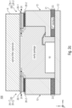
- Fig. 1 shows a schematic cross-sectional view through an package 100 for an optical radiation device 10 (10-1, 10-2) according to an embodiment.
- the package 100 for the optical radiation device 10 comprises a base structure 12 having arranged thereon the optical radiation device 10, a lid element 14 (e.g. optically transparent for IR, UV or visible radiation) bonded to the base structure 12 and defining a cavity 16 between the base structure 12 and the lid element 14.
- the package 100 further comprises a bond structure 20 in a bonding region 22 between the base structure 12 and the lid element 14.
- the bond structure 20 is arranged to provide an adhesive bond between the base structure 12 and the lid element 14.
- the bond structure 20 comprises a diffusion layer 20-1 having a gas diffusive material or gas diffusive structure for providing a gas diffusion path 24 between the closed cavity 16 and the surrounding atmosphere 18.
- the optical radiation device 10 may be formed as an optical radiation emitter 10-1 or an optical radiation detector 10-2.
- the package 100 may comprise an acoustically tight gas diffusion path 24, e.g. with an acoustically tight bond structure 20.
- the package 100 may be arranged as an acoustically tight package 100.
- the bond structure 20 may comprise a diffusion layer 20-1, 20-2 having a parasitic gas diffusive material or parasitic gas diffusive structure for providing an acoustically tight parasitic gas diffusion path 24 between the cavity 16 and the surrounding atmosphere 18.
- the term "acoustically tight” may define a condition of the package 100 and, for example, of the bond structure 20 of the package 100, wherein a first order low frequency (roll-off corner frequency or high-pass corner frequency) is (about) 0.01 Hz (or between 0.005 and 0,05 Hz).
- a first order low frequency (roll-off corner frequency) of (about) 0.01 Hz (within ⁇ 10%) may result in an attenuation of 72 dB (equals a factor of 4000) at a target frequency of 40 Hz (within ⁇ 5 Hz), for example.
- the acoustically tight package 100 may ensure that the cavity 16 is acoustically isolated from the sample area (interaction area) in the measurement cell of a sensor device (see Fig. 8a-b , for example).
- the periodically chopped radiation emitted from the (PAS) radiation source may be sufficiently attenuated and suppressed, i.e. acoustically kept away from the sample area (interaction area) in the measurement cell of a sensor device, to ensure that the gas measurements are not compromised.
- acoustical influences or interferences from the environment may be sufficiently attenuated and suppressed, i.e. acoustically kept away from the cavity 16 of the package 100.
- the cavity 16 of the package 100 may be acoustically isolated from the environment, e.g. from external noise.
- parasitic gas may relate to any gas or gas composition, which affects or (negatively) influences the operation of the optical radiation device.
- a parasitic gas may be any gas or gas composition, which may have a negative effect to the functionality of the optical radiation structure.
- the optical radiation device 10 may be an IR emitter (e.g. a MEMS heater) and, thus, part of a PAS gas detector (see Fig. 8a , for example) for detecting a target gas G TAR , wherein the bond structure 20 is arranged to provide the diffusion path 24 for a (parasitic) gas G CAV (from or to the cavity 16) through the bond structure 20.
- the optical radiation device 10 may be (alternatively) an optical radiation detector and part of a NDIR gas detector (e.g. a thermopile, see Fig. 8b , for example) for detecting a target gas G TAR , wherein the bond structure 20 is arranged to provide the diffusion path 24 for a parasitic gas G CAV through the bond structure 20.
- a NDIR gas detector e.g. a thermopile, see Fig. 8b , for example
- Embodiments of the present disclosure are described with respect to gases or gas components, e.g., in the environmental air.
- the description of the different embodiments is equally applicable to liquids or liquid components in the environmental medium.
- the general term "fluid" may relate to a liquid or a gas.
- the description with respect to a gas or gas component is equally applicable to a liquid or liquid component.
- a target gas or target gas component is the gas or gas component to be detected or sensed and may comprise at least one of CO, CO 2 , O 3 , NO X , methane, etc., for example.
- the present concept is equally applicable to sense a target liquid or a target liquid component in the environmental medium.
- the target gas G TAR and the parasitic gas G CAV may relate to the same gas or gas component or may relate to different gases or different gas components.
- the target gas or target gas component to be detected or sensed and the (parasitic) gas G CAV may relate to gases or gas components having similar absorption lines (which are reactive on similar bands).
- the gas (or parasitic gas) G CAV may relate to any gas content in the cavity 16 which may affect an operating parameter, e.g. the sensitivity, of the optical radiation device 10 or of a sensor device which comprises the optical radiation device 10.
- the gas G CAV may be the target gas to be sensed or another component, e.g. water vapor, which will also vent out through the diffusion path 24.
- the target gas or target gas component G TAR to be detected or sensed may comprise CO (carbon monoxide), for example, wherein the (parasitic) gas G CAV may comprise CO 2 (carbon dioxide), because CO and CO 2 have similar absorption lines (bands).
- the target gas or target gas component to be detected or sensed may comprise CO 2 (carbon dioxide), for example, wherein the (parasitic) gas G CAV may comprise CO (carbon monoxide).
- the bond structure 20 is arranged to have a permeability for the gas G CAV for providing a gas exchange (of gas G CAV ) through the diffusion path 24 between the cavity and the surrounding environment with a diffusion time constant T D which is below 600, 300, 100 or 10 seconds or between 2 and 600, 300, 100, or 10 seconds.
- the diffusion time constant T D is, in the context of the present description, the time duration until the gas G CAV is fully driven out of the package and/or at the same level (equilibrium) with the ambient gas concentration, such as the concentration of the gas G CAV in the environment.
- the diffusion time constant T D of the gas G CAV is based on the gas diffusivity or gas permeability along the diffusion path 24 through the bond structure 20.
- the bond structure 20 comprises the diffusion layer having a gas diffusive material or a gas diffusive structure (for the gas G CAV )
- the bond structure 20 allows the transmission of the gas G CAV in both directions, i.e., both into and out of the cavity 16 (to allow a gas exchange of the gas G CAV ).
- gas permeability or "gas diffusivity” refers to the permeability of the interface 20 to gas.
- the bond structure 20 comprises the diffusion layer 20-1 and the adhesive layer 20-2 in the bonding region for providing the adhesive bond between the base structure 12 and the lid element 14.
- the diffusion layer 20-1 may be formed as a layer which is highly permeable for the gas G CAV , for providing the diffusion path 24 of the gas G CAV through the bond structure 20, i.e., from the cavity 16 to the surrounding environment.
- the diffusion layer 20-1 may comprise a gas diffusive material or a gas diffusive structure for the gas G CAV (e.g. in form of very thin pores or capillary tubes with an effective pore size or tube diameter in a range of about 1 ⁇ m and 30 ⁇ m) for providing the diffusion path 24 between the close cavity 16 and the surrounding atmosphere.
- the adhesive layer 20-2 may be formed as a double-sided tape which is attached to a side (surface region) of the diffusion layer 20-1, e.g., a PTFE layer or a PTFE impregnated adhesive materials, polymers, such as polyamide or cellulose acetate, or ceramic materials.
- the bond structure (bondline) 20 may comprise a typical overall thickness between (around) 30 ⁇ m and 100 ⁇ m, for example.
- the package 100 may comprise an exemplary lateral extension "X" between 2 mm and 8 mm, between 3 mm and 5 mm or of about 4 mm.
- the (lateral) thickness X 13 of the wall 13 may be in a range of about 0.1 mm to 1 mm.
- the diffusion layer 20-1 may comprise a thickness t 20-1 in a range between 10 ⁇ m and 200 ⁇ m or between 30 ⁇ m and 100 ⁇ m, wherein the adhesive layer 20-2 may comprise a (vertical) thickness t 20-2 of about 5 ⁇ m to 100 ⁇ m.
- the diffusion layer 20-1 and the adhesive layer 20-2 may comprise a (lateral) width w 20-1 , w 20-2 of about 0.1 mm to 2 mm which corresponds to the (lateral) wall thickness X 13 .
- the (lateral) thickness t 20-2 of the adhesive filler layer 20-2 is in a range between 5 ⁇ m and 100 ⁇ m.
- the bond structure 20 may comprises the diffusion layer 20-1 and the adhesive layer 20-2 in the bonding region 22 for providing the diffusion path 24 between the cavity 16 and the surrounding environment and for providing the adhesive bond between the base structure 12 and the lid element 14.
- the bond structure 20 may further comprise a further adhesive layer 20-3, wherein the diffusion layer 20-1 having a gas diffusive material is sandwiched between the adhesive layer 20-2 and the further adhesive layer 20-3.
- the bond structure 20 comprises a stack of a plurality of alternating adhesive layers 20-2 and (sandwiched) gas diffusive layers 20-1.
- At least one of the base structure 12 and the lid element 14 may further comprise a supporting structure 28, e.g. in form of a merlon-like structure for mechanically stabilizing the diffusion layer 20-1.
- the bond structure 20 may comprise an adhesive layer 20-2 in the bonding region 22 for providing the adhesive bond between the base structure 12 and the lid element 14.
- the adhesive layer (filler adhesive) 20-2 may comprise gas diffusive filler particles 25 for providing the diffusion path 24 through the bond structure 20.
- the adhesive layer 20-2 may comprise a PTFE material or a PTFE impregnated adhesive for providing the diffusion path 24 of the gas G CAV through the bond structure 20.
- the diffusion time constant T D can be set to a requested value.
- the more filler particles 25 in the adhesive layer 20-2 and the greater the dimension (e.g. the vertical cross-sectional area) of adhesive layer 20-2 the shorter is the (set) diffusion time constant T D .
- the adhesive layer 20-2 may comprise a gas diffusion section 26 for providing the gas diffusion path 24 through the bond structure 20.
- the diffusion section 26 may be formed as at least one (or a plurality of) channel(s) 26 through the adhesive layer 20-2 and comprises a gas diffusive material.
- the diffusion section 26 in the adhesive layer 20-2 may comprise a gas diffusive filler material or gas diffusive filler particles embedded in the adhesive layer 20-2.
- a part (section) of the adhesive layer 20-2, which laterally extends through the bond structure 20, comprises the gas diffusive filler material or gas diffusive filler particles and forms the diffusion path 24.
- a plurality of gas diffusion sections 26 of the adhesive layer 20-2 may comprise the gas diffusive filler material or gas diffusive filler particles and may form the diffusion path 24.
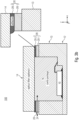
- Fig. 2a-d show further schematic cross-sectional views through further possible implementations of the package 100 for an optical radiation device 10 according to further embodiments.
- the further illustrations of the package 100 in Figs. 2a-d should show (and clarify) that the following evaluations of the present concept for the package 100 for an optical radiation device 10 are equally applicable to different configurations (designs) of the respectively bonded base structure 12 and lid element 14 and to different positions of the bonding region 22 with the bond structure 20 between the base structure 12 and the lid element 14.
- the base structure (basis element) 12 may comprise the (vertically extending) side walls 13.
- the lid element 14 may comprise the (vertically extending) side walls 13.
- the base structure 12 and the lid element may each comprises a part of the (vertically extending) side walls 13.
- the bonding region 22 with the bond structure is formed between the base structure 12 and the lid element 14.
- the lid element 14 is placed (arranged) on top of the base structure 12.
- the following evaluations of the present concept for the package 100 are also applicable to configurations with further "intermediate elements" in the base structure 12, the lid element 14 and/or the side walls 13 as far as the intermediate elements are bonded to the base structure 12, the lid element 14 and/or the side walls 13 and provide for the package 100.
- the bond structure 20 may be formed (placed) at any height position of the side walls 13, e.g. at a top position as shown in Fig. 1 , at a bottom position as shown in Fig. 2a or at an intermediate position as shown in Fig. 2b .
- the bond structure 20 may be circumferentially arranged in the side walls 13 and parallel to the lateral (reference) plane, for example, for facilitating the manufacturing process.
- the side wall 13 of the package 100 is arranged between and adhesively fixed (bonded) to the base structure (base element) 12 and the lid element (lid structure) 14.
- a further bond structure 21 may be arranged in a further bond region 23 between the side wall 13 and the base structure 12 wherein the bond structure 20 is arranged in the bond region 22 between the side wall 13 and the lid element 14.
- the bond region 22 and the further bond region 23 are vertically spaced from each other.
- the further bond region 23 may be formed (placed) at a bottom position of the side wall(s) 13 as shown in Fig. 2c .
- a least one (or both) of the bond region 20 and the further bond region 21 may be placed at an intermediate position of the side wall(s) 13.
- the further bond structure 21 may be arranged in a further bond region 23 between the side wall 13 and the base structure 12, wherein the bond structure 20 is arranged in the bond region 22 between the side wall structure 13 and the lid element 14.
- the bond region 22 and the further bond region 23 are vertically spaced from each other.
- the further bond region 23 may be formed (placed) at a bottom position of the side wall(s) 13.
- a least one (or both) of the bond region 22 and the further bond region 23 may be placed at an intermediate position of the side wall(s) 13.
- the bond structure 20 and the further bond structure 21 may form together the diffusion paths 24, 24-1.
- the further bond structure 21 may comprise an adhesive layer 21-2 in the further bonding region 23 for providing the adhesive bond.
- the adhesive layer 21-2 of the further bond structure may comprise gas diffusive filler particles 25 for providing a further diffusion path 24-1 through the bond structure 20.
- the adhesive layer 21-2 may comprise a PTFE material or a PTFE impregnated adhesive for providing the further diffusion path 24-1 of the target gas G TAR through the further bond structure 21.
- the further bond structure 21 may comprise a diffusion layer 21-1 having a gas diffusive material or gas diffusive structure for providing a further gas diffusion path 24-1 between the closed cavity 16 and the surrounding atmosphere.
- the further bond structure 21 may comprise the adhesive layer 21-2 in the further bonding region 23 for providing the adhesive bond.
- the further bond structure 21 may comprise the same arrangement and function as the bond structure 20 for providing the further gas diffusion path 24-1.
- Figs. 1 and 2a-d describe a design of a package 100 that has a defined gas diffusion path 24 (24-1) to allow an out-diffusion of gases inside an optical radiation device 10, e.g. an emitter (PAS) 10-1 or a detector (NDIR) 10-2.
- a defined exchange with the ambient atmosphere, e.g. environmental air, will be used to further and further dilute the gas G CAV inside the emitter / detector package 100.
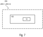
- the package 100 may be part of a gas sensor device (see Figs. 7 and 8a-b ). Once the gas G CAV is fully driven out and/or at the same level as (in an equilibrium with) the ambient gas concentration, the sensor device can be calibrated. A further increase of gas G CAV (e.g. due to operation) will be avoided due to the constantly given diffusivity of the package 100 through the bond structure 20 providing the diffusion path 24 between the cavity 16 and the surrounding atmosphere.
- a gas G CAV will diffuse quickly inside the emitter / detector package 100 and can be calibrated out as it will be present in the sensor cell (sensor device) and in the emitter / detector package 100 in equal amount.
- the cavity 16 is enclosed by the base structure 12 and the lid element (lid structure) 14, wherein the lid element 14 may form or comprise an optical filter, for example.
- This diffusion layer (of the bond structure) 20 can be integrated in front- or backend on the lid structure (e.g. a filter) 14 or base structure 12 of the cavity package 100 directly.
- the bond structure 20 may comprise an adhesive layer (or layer stack). Alternatively, there could be filler particles directly integrated into the adhesive layer to modify its diffusion properties.
- Fig. 3a-d show schematic cross-sectional views through an acoustically tight optical radiation device package according to further embodiments together with an enlarged sectional view of the bond structure.
- the bond structure 20 may comprises (at least) the diffusion layer 20-1 and the adhesive layer 20-2 in the bonding region 22 for providing the diffusion path 24 between the cavity 16 and the surrounding environment and for providing the adhesive bond between the base structure 12 and the lid element 14.
- the diffusion layer 20-1 is attached to the lid element 14, wherein the adhesive layer is attached to the wall element 13 of the base structure 12. Further, the opposing surfaces of the diffusion layer 20-1 and the adhesive layer 20-2 are attached to each other to form the bond structure 20.
- the diffusion layer 20-1 is attached to the wall element 13 of the base structure 12, wherein the adhesive layer is attached to the lid element 14. Further, the opposing surfaces of the adhesive layer 20-2 and of the diffusion layer 20-1 are attached to each other to form the bond structure 20.
- the bond structure 20 may be formed as a triple stack with adhesive layers 20-2 and 20-3 of both sides of the diffusion layer 20-1.
- the bond structure 20 may further comprise the further adhesive layer 20-3, wherein the diffusion layer 20-1 having a gas diffusive material is sandwiched between the adhesive layer 20-2 and the further adhesive layer 20-3.
- the bond structure 20 may comprise a stack of a plurality of alternating adhesive layers 20-2, 20-3 and diffusion layers 20-1. As exemplarily shown in Fig. 3-d , each diffusion layer 20-1 is sandwiched between two adhesive layers 20-2, 20-3, for example.
- Fig. 4 shows a schematic cross-sectional view through an optical radiation device package according to a further embodiment together with an enlarged sectional view of the bond structure.
- the base structure 12 and the lid element 14 may further comprise a supporting structure 28, e.g., in the form of a merlon- or pinnacle-like structure or of bumps, for mechanically stabilizing the diffusion layer 20-1.
- the supporting or stabilization structure may be part of the base structure 12 or the lid element 14 or of both.
- the stabilization structure 28 is shown as part of the base structure 12 on top of the wall elements 13.
- the stabilization structures 28 are arranged to avoid a deflection of the lid element 14 (having an optical filter, for example) in case the diffusion layer 20-1 comprises a (relatively) soft and deformable material, e.g., a foam-like material.
- the diffusion layer 20-1 comprises, for example, a soft foam-like material
- the merlon-like structures around the package frame are arranged to stabilize the assembly by offering direct mechanical contact between the base structure 12 and the adhesive layer 20-2 which is attached to the lid element 14, for example, or between the base structure 12 and the lid element 14.
- the merlon-like structures may be formed at the lid element and may provide direct mechanical contact to the adhesive layer 20-2 which is attached to the top side of the wall elements 13 of the base structure 12, or directly to the wall elements 13 of the base structure 12.
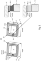
- Fig. 5 shows a schematic 3D view of an package 100 for an optical radiation device 10 together with an enlarged cross-sectional view of the bond structure 20 according to a further embodiment.
- the adhesive layer 20-2 comprises a gas diffusion section 26 for providing the gas diffusion path 24 through the bond structure 20.
- the diffusion section 26 may be formed as at least one channel 26 or a plurality of channels 26 through the adhesive layer 20-2 and comprises a gas diffusive material.
- the diffusion section 26 may comprise a gas diffusive filler material or gas diffusive filler particles embedded in the adhesive layer 20-2.
- the section 26 of the adhesive layer 20-2 which laterally extends through the bond structure 20, comprises the gas diffusive filler material or gas diffusive filler particles and forms the diffusion path 24.
- a plurality of sections of the adhesive layer 20-2, which laterally extend through the bond structure 20, may comprise the gas diffusive filler material or gas diffusive filler particles and may form the diffusion path 24.
- the diffusion layer 20-1 does not fully surround the interface (bond structure) 20 but is partially formed as a section 26 of the bond structure 20.
- the diffusion section(s) 26 in the adhesion section (layer) 20-2 at least one or a plurality of diffusion channels 24 are formed through the adhesion layer(s) 20-2.
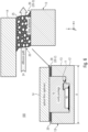
- Fig. 6 shows a schematic cross-sectional view through an acoustic type optical radiation device package 100 according to a further embodiment together with an enlarged view of the bond structure 20.
- the adhesive layer (filler adhesive) 20-2 of the bond structure 20 may comprise gas diffusive filler particles 25 (filler particles which are diffusive for the gas G CAV ) for providing the diffusion path 24 through the bond structure 20.
- the adhesive layer 20-2 may comprise a PTFE material or a PTFE impregnated adhesive for providing the diffusion path 24 of the gas G CAV through the bond structure 20.
- the diffusion time constant T D can be set to a predefined value.
- the more filler particles in the adhesive layer 20-2 and the greater the dimension (e.g., the vertical cross sectional area) of the adhesive layer 20-2 the shorter is said diffusion time constant T D .
- the adhesive layer 20-2 of the bond structure 20 may comprise diffusion time enhancing filter particles 25, e.g., in a standard adhesive material.
- the filler particles 25, e.g., PTFE material, allow a quicker diffusion of the gas G CAV by having a shorter effective path length of the glue interface (bond structure) 20 to the outside (ambient atmosphere).
- the package 100 uses a highly gas permeable structure or layer based on the filler particles 25 in the bond structure (interface) 20 of the cavity package 100.
- the present concept can be used in physical gas sensors, such as in photoacoustic spectroscopy (PAS) and non-dispersive infrared (NDIR) sensors.
- PAS photoacoustic spectroscopy
- NDIR non-dispersive infrared
- a potential method to improve the emitter performance is to make one element (the bond structure 20) of its construction 'breathable', i.e. allow exchange of gas, but not compromise acoustic tightness.
- An adhesive 20-2 used to retain the lid element 14, which forms or comprises an IR filter, in place can be used wherein the adhesive may contain a PTFE or a similar gas exchanging / high permeability filler material. This structure allows the exchange of gas (parasitic gas G CAV ) far more readily through the adhesive material.
- the high gas permeability material suspended in the adhesive 20-2 allows to provide an cavity 16, but still allow the transmission of gas both into and out of the emitter cavity 16.
- the gas exchanging material does not necessarily need to form a solid pathway between interior and exterior if the adhesive already has some ability to allow gas exchange, it needs to have a much higher rate of gas permeability. An improved gas transmission may also occur along the interfaces between the adhesive and the more gas permeable filler.
- the high gas permeability material in the adhesive 20-2 would allow equalization of (atmospheric) pressure between the IR emitter interior 16 and the gas measurement chamber (see Fig. 8a , for example) in which it sits. It would also allow any gas, e.g. CO 2 , generated from curing materials to escape. If the diffusion time of gas through the material (bond structure 20) is chosen to be much slower than that of the gas, e.g. CO 2 , entering the measurement chamber (see Fig. 8a , for example), the gas, e.g. CO 2 , measurement should not be affected.
- the high gas permeability impregnated adhesive 20-2 could potentially be cured by thermal means, since the adhesive material's breathability would allow pressure inside the ceramic cavity to equalize on cooling.
- the gas exchange through the high gas permeability material 20-1 may not be fast enough during thermal curing (during the manufacturing process) to overcome internal air pressure changes, so that a slow ramp in heating may applied.
- the adhesive 20-1 will not be pushed out of the joint between the base structure 12, e.g. a ceramic cavity, and the lid element 14, e.g. an IR filter, by internal air pressure, creating voids in the adhesive 20-1.
- the IR filter may be formed as a silicon IR filter so that filtered IR light emerges from the IR filter.
- the adhesive material 20-2 of the bond structure 20 retains the lid element (filter) 14 on the sidewalls of the (ceramic) cavity package 100.
- the package 100 may comprise an acoustically tight gas diffusion path 24, e.g. with an acoustically tight bond structure 20.
- the package 100 may be arranged as an acoustically tight package 100.
- the bond structure 20 may comprise a diffusion layer having a parasitic gas diffusive material or parasitic gas diffusive structure for providing an acoustically tight parasitic gas diffusion path 24 between the cavity 16 and the surrounding atmosphere 18.
- the fluid sensor 200 may be formed as a PAS gas detector (fluid detector) 200-1, wherein the optical radiation device 10 is an IR emitter or a laser or LED 10-1 and part of the PAS gas detector 200-1 for detecting a target gas G TAR .
- the bond structure 20 of the package 100 is arranged to provide the diffusion path 24 for a gas G CAV through the bond structure 20.
- the bond structure 20 of the package 100 may be arranged to provide an acoustically tight diffusion path 24 for a parasitic gas G PAR through the bond structure 20.
- the fluid sensor 200 may be formed as an NDIR gas detector 200-2, wherein the optical radiation device 10 is an optical radiation detector 10-2, e.g., a thermopile detector, for detecting a target gas G TAR , wherein the bond structure 20 is arranged to provide the diffusion path 24 for a gas G CAV through the bond structure 20.
- the optical radiation device 10 is an optical radiation detector 10-2, e.g., a thermopile detector, for detecting a target gas G TAR
- the bond structure 20 is arranged to provide the diffusion path 24 for a gas G CAV through the bond structure 20.
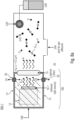
- Fig. 8a shows a schematic block diagram of a fluid (gas or liquid) sensing device 200-1 in the form of a PAS gas sensor having the package 100 for an optical radiation device 10 according to a further embodiment.
- the PAS gas sensor 200-1 comprises a light source 10-1 which is arranged in the package 100, e.g. an the acoustically tight package 100.
- the light source 10-1 may comprise an infrared emitter or a laser diode, for example.
- the light source 10-1 may be periodically chopped.
- the package 100 comprises an optical filter, which is, for example, part of the lid element 14, for a wavelength selection.
- the gas sensor device 200 further comprises a sample area (interaction area) 210 where the light or radiation R between the light source 10-1 and the detector 220 interacts with the environmental medium.
- the detector 220 may be formed, for example, as a (capacitive or piezoelectric) MEMS microphone.
- the molecules of the target gas G TAR e.g. CO 2 molecules, absorb the light R emitted from the light source 10-1 and filtered by the optical filter 14.
- the light absorption causes a periodic local change of temperature in the interaction area 210, which results in corresponding pressure changes in the interaction area 210.
- the periodic pressure changes are detected by the acoustic detector 220, e.g., a MEMS microphone, which is optimized for low frequency operation.
- the acoustic detector 220 may be read out by means of an ASIC 230, for example.
- the closed interaction area may be accessible through a fluid port 240 for fluid (gas or liquid) diffusion.
- embodiments may relate to a PTFE impregnated adhesive to secure of the lid element 14, e.g. an IR filter, to the base structure 12 defining a cavity 16, e.g. a ceramic cavity, on the PAS gas sensor 200-1, e.g. a PAS CO 2 sensor.
- a PTFE impregnated adhesive to secure of the lid element 14, e.g. an IR filter, to the base structure 12 defining a cavity 16, e.g. a ceramic cavity, on the PAS gas sensor 200-1, e.g. a PAS CO 2 sensor.
- Fig. 8b shows a schematic block diagram of a fluid (gas or liquid) sensing device in the form of an NDIR gas sensor 200-2 having the package 100 for an optical radiation device 10 according to a further embodiment.
- the NDIR sensor device 200-2 comprises a radiation source 250, the package 100 for the detector 10-2, the package 100 comprises the lid element 14 having filter element for a wavelength selection and the sample area (interaction area) 210 which is accessible by means of a gas inlet/outlet 240.
- the interaction area 210 the light R between the light source 250 and the detector 10 interacts with the environmental medium, e.g. the target gas G TAR .
- the main components of the NDIR sensor 200-2 are an infrared IR source 250, the sample chamber or light tube 210, the light filter 14 and the infrared detector 10 in the package 100.
- the IR light R is directed through the sample chamber 210 towards the packaged detector 10.
- the target gas G TAR in the sample chamber 210 causes an absorption of a specific wavelength and the intensity change at this wavelength is measured by the detector 10 to determine the target gas concentration.
- the optical filter 14 in front of (upstream to) the detector is arranged to eliminate all light except the wavelength that the target gas molecules can absorb.
- the bond structure 20 of the package 100 may be arranged to provide an acoustically tight diffusion path 24 for a parasitic gas G PAR through the bond structure 20.
- Embodiments describe an improvement to existing cavity packages for gas sensing, which often contain a certain amount of the target gas interfering with the IR radiation as gas G CAV .
- a defined gas ventilation path 24 is provided inside the cavity package 100, wherein the cavity package 100 allows gas G CAV (parasitic gas) to penetrate at a specific rate.
- the cavity package 100 may be acoustically tight but also allows gas G CAV (parasitic gas) to penetrate at a specific rate.
- the ventilation path 24 can be formed as one or more separate (diffusion) layers or a diffusion material 20-1 embedded into existing adhesive layers 20-2 and/or 20-3.
- the package 100 for an optical radiation device 100 may provide a drift stabilization of a gas sensing device 200, e.g., a PAS system 200-1 or a NDIR system 200-2 for gas sensing.
- a gas sensing device 200 e.g., a PAS system 200-1 or a NDIR system 200-2 for gas sensing.
- the package 100 is inexpensive to manufacture, wherein there is no need to have the gas content fully settled and under control prior to calibration of the gas sensor device.
- the bond structure 20 can inexpensively be integrated in the package.
- the package 100 provides a defined acoustical tightness for the gas sensor device 200, e.g., a PAS sensor 200-1 or an NDIR sensor 200-2, so that the package 100 can be inexpensively integrated into the measurement cell.
- the package 100 can be formed to have high mechanical robustness as well as high resilience to temperature cycles.
Landscapes
- Physics & Mathematics (AREA)
- Spectroscopy & Molecular Physics (AREA)
- General Physics & Mathematics (AREA)
- Life Sciences & Earth Sciences (AREA)
- Health & Medical Sciences (AREA)
- Chemical & Material Sciences (AREA)
- Analytical Chemistry (AREA)
- Biochemistry (AREA)
- General Health & Medical Sciences (AREA)
- Immunology (AREA)
- Pathology (AREA)
- Engineering & Computer Science (AREA)
- Microelectronics & Electronic Packaging (AREA)
- Computer Hardware Design (AREA)
- Investigating Or Analysing Materials By Optical Means (AREA)
Claims (20)
- Ein Optische-Strahlungsvorrichtung-Package (100), das folgende Merkmale aufweist:eine Basisstruktur (12), auf der die optische Strahlungsvorrichtung (10; 10-1, 10-2) angeordnet ist,ein optisch transparentes Deckelelement (14), das mit der Basisstruktur (12) verbunden ist und einen Hohlraum (16) zwischen der Basisstruktur (12) und dem Deckelelement (14) definiert, wobei die optische Strahlungsvorrichtung (10; 10-1, 10-2) in dem Hohlraum (16) angeordnet ist, undeine Verbindungsstruktur (20) in einer Verbindungsregion (22) zwischen der Basisstruktur (12) und dem Deckelelement (14), wobei die Verbindungsstruktur (20) angeordnet ist, um eine Haftverbindung zwischen der Basisstruktur (12) und dem Deckelelement bereitzustellen,dadurch gekennzeichnet, dass die Verbindungsstruktur (20) eine Diffusionsschicht (20-1, 20-2) mit einem Gasdiffusionsmaterial oder einer Gasdiffusionsstruktur aufweist, um einen Gasdiffusionsweg (24) zwischen dem Hohlraum (16) und der umgebenden Atmosphäre (18) bereitzustellen.
- Das Package (100) gemäß Anspruch 1, wobei die optische Strahlungsvorrichtung (10) ein optischer Strahlungsemitter (10-1) oder ein optischer Strahlungsdetektor (10-2) ist.
- Das Package (100) gemäß Anspruch 1 oder 2, wobei das Package (100) akustisch dicht ist und einen akustisch dichten Gasdiffusionsweg (24) aufweist.
- Das Package (100) gemäß einem der Ansprüche 1 bis 3, wobei die Verbindungsstruktur (20) eine Diffusionsschicht (20-1, 20-2) mit einem parasitären Gasdiffusionsmaterial oder einer parasitären Gasdiffusionsstruktur aufweist, um einen akustisch dichten parasitären Gasdiffusionsweg (24) zwischen dem Hohlraum (16) und der umgebenden Atmosphäre (18) bereitzustellen.
- Das Package (100) gemäß einem der vorhergehenden Ansprüche, wobei die optische Strahlungsvorrichtung (10) ein IR-Emitter (10-1) ist und dazu konfiguriert ist, als Teil eines Photoakustische-Spektrosopie(PAS) -Gasdetektors (200-1) zum Erfassen eines Zielgases verwendet zu werden, wobei die Verbindungsstruktur (20) angeordnet ist, um den akustisch dichten Diffusionsweg (24) für ein Gas durch die Verbindungsstruktur (20) bereitzustellen.
- Das Package (100) gemäß einem der Ansprüche 1 bis 4, wobei die optische Strahlungsvorrichtung (10) ein optischer Strahlungsdetektor (10-2) ist und dazu konfiguriert ist, als Teil eines nicht-dispersiven Infrarot(NDIR) -Gasdetektors (200-2) zum Erfassen eines Zielgases verwendet zu werden, wobei die Verbindungsstruktur (20) angeordnet ist, um den akustisch dichten Diffusionsweg (24) für ein Gas (GCAV) durch die Verbindungsstruktur (20) bereitzustellen.
- Das Package (100) gemäß einem der vorhergehenden Ansprüche, wobei die Verbindungsstruktur (20) angeordnet ist, um eine Gasdurchlässigkeit aufzuweisen, um einen Gasaustausch durch den Diffusionsweg (24) zwischen dem Hohlraum (16) und der umgebenden Umgebung mit einer Diffusionszeitkonstante bereitzustellen, die unter 600, 300, 100 oder 10 Sekunden liegt.
- Das Package (100) gemäß einem der vorhergehenden Ansprüche, wobei die Verbindungsstruktur (20) eine Haftschicht (20-2) in der Verbindungsregion (22) aufweist, um die Haftverbindung zwischen der Basisstruktur (12) und dem Deckelelement (14) bereitzustellen.
- Das Package (100) gemäß Anspruch 8, wobei die Haftschicht (20-2) Gasdiffusionsfüllstoffpartikel (25) aufweist, um den Diffusionsweg (24) durch die Verbindungsstruktur (20) bereitzustellen.
- Das Package (100) gemäß Anspruch 8 oder 9, wobei die Haftschicht (20-2) ein PTFE-Material oder ein PTFE-imprägniertes Haftmittel aufweist, um den Diffusionsweg (24) des Zielgases durch die Verbindungsstruktur (20) bereitzustellen.
- Das Package (100) gemäß Anspruch 8, wobei die Haftschicht (20-2) einen Gasdiffusionsabschnitt (26) aufweist, um den Gasdiffusionsweg (24) durch die Verbindungsstruktur (24) bereitzustellen.
- Das Package (100) gemäß Anspruch 11, wobei der Diffusionsabschnitt (26) als zumindest ein Kanal durch die Haftschicht (20-2) ausgebildet ist und ein Gasdiffusionsmaterial aufweist.
- Das Package (100) gemäß Anspruch 11 oder 12, wobei der Diffusionsabschnitt (26) ein Gasdiffusionsfüllstoffmaterial oder Gasdiffusionsfüllstoffpartikel aufweist, die in der Haftschicht (20-2) eingebettet sind.
- Das Package (100) gemäß einem der Ansprüche 8 bis 13, wobei die Verbindungsstruktur (20) ferner eine weitere Haftschicht (20-3) aufweist, wobei die Diffusionsschicht (20-1) mit einem Gasdiffusionsmaterial zwischen der Haftschicht (20-2) und der weiteren Haftschicht (20-3) angeordnet ist.
- Das Package (100) gemäß einem der vorhergehenden Ansprüche, wobei die Basisstruktur (12) und/oder das Deckelelement (14) ferner eine Tragestruktur (28), z. B. in Form einer zinnenartigen Struktur, aufweist, um die Diffusionsschicht (20-1) mechanisch zu stabilisieren.
- Das Package (100) gemäß einem der vorhergehenden Ansprüche, wobei die Verbindungsstruktur (20) einen Stapel aus einer Mehrzahl von abwechselnden Haftschichten (20-2, 20-3) und Gasdiffusionsschichten (20-1) aufweist.
- Das Package (100) gemäß einem der vorhergehenden Ansprüche, das ferner eine Zwischenwandstruktur (13) zwischen der Basisstruktur (12) und dem Deckelelement (14) aufweist,wobei eine weitere Verbindungsstruktur (21) in einer weiteren Verbindungsregion (23) zwischen der Zwischenwandstruktur (13) und dem Deckelelement (14) angeordnet ist, und wobei die Verbindungsstruktur (20) in der Verbindungsregion (22) zwischen der Zwischenwandstruktur (13) und der Basisstruktur (12) angeordnet ist,
oderwobei eine weitere Verbindungsstruktur (21) in einer weiteren Verbindungsregion (23) zwischen der Zwischenwandstruktur (13) und der Basisstruktur (12) angeordnet ist, und wobei die Verbindungsstruktur (20) in der Verbindungsregion (22) zwischen der Zwischenwandstruktur (13) und dem Deckelelement (14) angeordnet ist. - Ein Fluidsensor (200; 200-1, 200-2), der folgende Merkmale aufweist:
das Optische-Strahlungsvorrichtung-Package (100) gemäß einem der vorhergehenden Ansprüche. - Der Fluidsensor (200-1) gemäß Anspruch 18,
wobei der Fluidsensor ein Photoakustische-Spektrosopie(PAS) -Gasdetektor (200-1) ist, wobei die optische Strahlungsvorrichtung ein IR-Emitter (10-1) und Teil des PAS-Gasdetektors (200-1) zum Erfassen eines Zielgases ist, und wobei die Verbindungsstruktur (20) angeordnet ist, um einen akustisch dichten Diffusionsweg (24) für ein Gas durch die Verbindungsstruktur (20) bereitzustellen. - Der Fluidsensor (200-2) gemäß Anspruch 18,
wobei der Fluidsensor ein nicht-dispersiver Infrarot(NDIR) -Gasdetektor (200-2) ist, wobei die optische Strahlungsvorrichtung ein optischer Strahlungsdetektor (10-2) und Teil des NDIR-Gasdetektors (200-2) zum Erfassen eines Zielgases ist, wobei die Verbindungsstruktur (20) angeordnet ist, um den Diffusionsweg (24) für ein Gas durch die Verbindungsstruktur (20) bereitzustellen.
Priority Applications (3)
| Application Number | Priority Date | Filing Date | Title |
|---|---|---|---|
| EP23158197.6A EP4421477B1 (de) | 2023-02-23 | 2023-02-23 | Gehäuse mit einer optischen strahlungsvorrichtung |
| US18/582,173 US20240288363A1 (en) | 2023-02-23 | 2024-02-20 | Package for an optical radiation device |
| CN202410193380.9A CN118533747A (zh) | 2023-02-23 | 2024-02-21 | 用于光学辐射设备的封装 |
Applications Claiming Priority (1)
| Application Number | Priority Date | Filing Date | Title |
|---|---|---|---|
| EP23158197.6A EP4421477B1 (de) | 2023-02-23 | 2023-02-23 | Gehäuse mit einer optischen strahlungsvorrichtung |
Publications (2)
| Publication Number | Publication Date |
|---|---|
| EP4421477A1 EP4421477A1 (de) | 2024-08-28 |
| EP4421477B1 true EP4421477B1 (de) | 2025-01-29 |
Family
ID=85381192
Family Applications (1)
| Application Number | Title | Priority Date | Filing Date |
|---|---|---|---|
| EP23158197.6A Active EP4421477B1 (de) | 2023-02-23 | 2023-02-23 | Gehäuse mit einer optischen strahlungsvorrichtung |
Country Status (3)
| Country | Link |
|---|---|
| US (1) | US20240288363A1 (de) |
| EP (1) | EP4421477B1 (de) |
| CN (1) | CN118533747A (de) |
Family Cites Families (7)
| Publication number | Priority date | Publication date | Assignee | Title |
|---|---|---|---|---|
| US7034304B2 (en) * | 2003-07-25 | 2006-04-25 | Honeywell International, Inc. | Chamber for gas detector |
| CN112437630B (zh) * | 2018-06-29 | 2024-08-13 | 豪夫迈·罗氏有限公司 | 用于检测体液中的至少一种分析物的完全可植入传感器元件及方法 |
| EP3550286B2 (de) * | 2019-04-17 | 2026-02-11 | Sensirion AG | Photo-akustische gassensorvorrichtung |
| EP3835757B1 (de) * | 2019-12-10 | 2023-02-15 | Infineon Technologies AG | Emitterverpackung für einen photoakustischen sensor |
| EP4078147A1 (de) * | 2019-12-20 | 2022-10-26 | SenTec AG | Sensor zur gasdetektion und verfahren zur herstellung |
| EP3984945A1 (de) * | 2020-10-14 | 2022-04-20 | Infineon Technologies AG | Verfahren zur herstellung einer emitterpackung für eine photoakustische sensoranordnung |
| CN115113217A (zh) * | 2021-03-19 | 2022-09-27 | 讯芯电子科技(中山)有限公司 | 光学传感器以及光学传感器制造方法 |
-
2023
- 2023-02-23 EP EP23158197.6A patent/EP4421477B1/de active Active
-
2024
- 2024-02-20 US US18/582,173 patent/US20240288363A1/en active Pending
- 2024-02-21 CN CN202410193380.9A patent/CN118533747A/zh active Pending
Also Published As
| Publication number | Publication date |
|---|---|
| US20240288363A1 (en) | 2024-08-29 |
| EP4421477A1 (de) | 2024-08-28 |
| CN118533747A (zh) | 2024-08-23 |
Similar Documents
| Publication | Publication Date | Title |
|---|---|---|
| KR101837073B1 (ko) | 광음향 기체 센서를 위한 통합된 ir 소스 및 음향 검출기 | |
| CN114207410B (zh) | 光声气体传感器设备 | |
| FI3550286T4 (fi) | Fotoakustinen kaasunilmaisinlaite | |
| US11733213B2 (en) | Photoacoustic detector unit, photoacoustic sensor and associated production methods | |
| CN108291849A (zh) | 光学压力传感器 | |
| US11609180B2 (en) | Emitter package for a photoacoustic sensor | |
| US10393591B2 (en) | Electromagnetic radiation detector using a planar Golay cell | |
| EP4421477A1 (de) | Gehäuse für eine optische strahlungsvorrichtung | |
| KR20230152135A (ko) | 광음향 가스 센서 디바이스 | |
| US20210349057A1 (en) | Fluid Sensor | |
| CN109313129A (zh) | 微电子传感器装置和用于制造微电子传感器装置的方法 | |
| US20250060338A1 (en) | Radiation source device | |
| JP2013185996A (ja) | 非分散型赤外線分析式ガス検知器 | |
| CN223815348U (zh) | X荧光分析仪 | |
| CN110887806B (zh) | 基于超材料的无滤波片型红外热辐射气体浓度传感器 | |
| JP5932294B2 (ja) | 受動光学式気体状排出物センサ | |
| EP4266044B1 (de) | Verkapselung eines photoakustischen detektors | |
| CN119269410B (zh) | 一种实时校准的高精度光纤光声气体传感系统及方法 | |
| CN219957333U (zh) | 用于多气体测量的微型红外光源及光声气体传感器 | |
| US11119037B2 (en) | Small form factor spectrally selective absorber with high acceptance angle for use in gas detection | |
| KR20060048577A (ko) | 가스 센서 모듈 및 그 제조 방법 | |
| CN115389442A (zh) | 气室及气体传感器 | |
| Theuss et al. | for CO2 | |
| JP2009174868A (ja) | 相関セル、ガス分析装置及び相関セルの組み立て方法 |
Legal Events
| Date | Code | Title | Description |
|---|---|---|---|
| PUAI | Public reference made under article 153(3) epc to a published international application that has entered the european phase |
Free format text: ORIGINAL CODE: 0009012 |
|
| STAA | Information on the status of an ep patent application or granted ep patent |
Free format text: STATUS: REQUEST FOR EXAMINATION WAS MADE |
|
| 17P | Request for examination filed |
Effective date: 20231215 |
|
| AK | Designated contracting states |
Kind code of ref document: A1 Designated state(s): AL AT BE BG CH CY CZ DE DK EE ES FI FR GB GR HR HU IE IS IT LI LT LU LV MC ME MK MT NL NO PL PT RO RS SE SI SK SM TR |
|
| GRAP | Despatch of communication of intention to grant a patent |
Free format text: ORIGINAL CODE: EPIDOSNIGR1 |
|
| STAA | Information on the status of an ep patent application or granted ep patent |
Free format text: STATUS: GRANT OF PATENT IS INTENDED |
|
| RIC1 | Information provided on ipc code assigned before grant |
Ipc: G01N 21/61 20060101ALN20240830BHEP Ipc: G01J 3/02 20060101ALI20240830BHEP Ipc: G01N 21/3504 20140101ALI20240830BHEP Ipc: G01N 21/17 20060101AFI20240830BHEP |
|
| INTG | Intention to grant announced |
Effective date: 20240911 |
|
| P01 | Opt-out of the competence of the unified patent court (upc) registered |
Free format text: CASE NUMBER: APP_54675/2024 Effective date: 20241004 |
|
| GRAS | Grant fee paid |
Free format text: ORIGINAL CODE: EPIDOSNIGR3 |
|
| GRAA | (expected) grant |
Free format text: ORIGINAL CODE: 0009210 |
|
| STAA | Information on the status of an ep patent application or granted ep patent |
Free format text: STATUS: THE PATENT HAS BEEN GRANTED |
|
| AK | Designated contracting states |
Kind code of ref document: B1 Designated state(s): AL AT BE BG CH CY CZ DE DK EE ES FI FR GB GR HR HU IE IS IT LI LT LU LV MC ME MK MT NL NO PL PT RO RS SE SI SK SM TR |
|
| REG | Reference to a national code |
Ref country code: GB Ref legal event code: FG4D |
|
| REG | Reference to a national code |
Ref country code: CH Ref legal event code: EP |
|
| REG | Reference to a national code |
Ref country code: DE Ref legal event code: R096 Ref document number: 602023001812 Country of ref document: DE |
|
| REG | Reference to a national code |
Ref country code: IE Ref legal event code: FG4D |
|
| PGFP | Annual fee paid to national office [announced via postgrant information from national office to epo] |
Ref country code: AT Payment date: 20250417 Year of fee payment: 3 |
|
| REG | Reference to a national code |
Ref country code: NL Ref legal event code: MP Effective date: 20250129 |
|
| PG25 | Lapsed in a contracting state [announced via postgrant information from national office to epo] |
Ref country code: NL Free format text: LAPSE BECAUSE OF FAILURE TO SUBMIT A TRANSLATION OF THE DESCRIPTION OR TO PAY THE FEE WITHIN THE PRESCRIBED TIME-LIMIT Effective date: 20250129 |
|
| PG25 | Lapsed in a contracting state [announced via postgrant information from national office to epo] |
Ref country code: RS Free format text: LAPSE BECAUSE OF FAILURE TO SUBMIT A TRANSLATION OF THE DESCRIPTION OR TO PAY THE FEE WITHIN THE PRESCRIBED TIME-LIMIT Effective date: 20250429 |
|
| PG25 | Lapsed in a contracting state [announced via postgrant information from national office to epo] |
Ref country code: FI Free format text: LAPSE BECAUSE OF FAILURE TO SUBMIT A TRANSLATION OF THE DESCRIPTION OR TO PAY THE FEE WITHIN THE PRESCRIBED TIME-LIMIT Effective date: 20250129 |
|
| PG25 | Lapsed in a contracting state [announced via postgrant information from national office to epo] |
Ref country code: PL Free format text: LAPSE BECAUSE OF FAILURE TO SUBMIT A TRANSLATION OF THE DESCRIPTION OR TO PAY THE FEE WITHIN THE PRESCRIBED TIME-LIMIT Effective date: 20250129 |
|
| PGFP | Annual fee paid to national office [announced via postgrant information from national office to epo] |
Ref country code: DE Payment date: 20250422 Year of fee payment: 3 |
|
| PG25 | Lapsed in a contracting state [announced via postgrant information from national office to epo] |
Ref country code: ES Free format text: LAPSE BECAUSE OF FAILURE TO SUBMIT A TRANSLATION OF THE DESCRIPTION OR TO PAY THE FEE WITHIN THE PRESCRIBED TIME-LIMIT Effective date: 20250129 |
|
| REG | Reference to a national code |
Ref country code: LT Ref legal event code: MG9D |
|
| PG25 | Lapsed in a contracting state [announced via postgrant information from national office to epo] |
Ref country code: NO Free format text: LAPSE BECAUSE OF FAILURE TO SUBMIT A TRANSLATION OF THE DESCRIPTION OR TO PAY THE FEE WITHIN THE PRESCRIBED TIME-LIMIT Effective date: 20250429 Ref country code: IS Free format text: LAPSE BECAUSE OF FAILURE TO SUBMIT A TRANSLATION OF THE DESCRIPTION OR TO PAY THE FEE WITHIN THE PRESCRIBED TIME-LIMIT Effective date: 20250529 |
|
| REG | Reference to a national code |
Ref country code: AT Ref legal event code: MK05 Ref document number: 1763905 Country of ref document: AT Kind code of ref document: T Effective date: 20250129 |
|
| PG25 | Lapsed in a contracting state [announced via postgrant information from national office to epo] |
Ref country code: HR Free format text: LAPSE BECAUSE OF FAILURE TO SUBMIT A TRANSLATION OF THE DESCRIPTION OR TO PAY THE FEE WITHIN THE PRESCRIBED TIME-LIMIT Effective date: 20250129 |
|
| PG25 | Lapsed in a contracting state [announced via postgrant information from national office to epo] |
Ref country code: LV Free format text: LAPSE BECAUSE OF FAILURE TO SUBMIT A TRANSLATION OF THE DESCRIPTION OR TO PAY THE FEE WITHIN THE PRESCRIBED TIME-LIMIT Effective date: 20250129 Ref country code: PT Free format text: LAPSE BECAUSE OF FAILURE TO SUBMIT A TRANSLATION OF THE DESCRIPTION OR TO PAY THE FEE WITHIN THE PRESCRIBED TIME-LIMIT Effective date: 20250529 |
|
| PG25 | Lapsed in a contracting state [announced via postgrant information from national office to epo] |
Ref country code: BG Free format text: LAPSE BECAUSE OF FAILURE TO SUBMIT A TRANSLATION OF THE DESCRIPTION OR TO PAY THE FEE WITHIN THE PRESCRIBED TIME-LIMIT Effective date: 20250129 Ref country code: GR Free format text: LAPSE BECAUSE OF FAILURE TO SUBMIT A TRANSLATION OF THE DESCRIPTION OR TO PAY THE FEE WITHIN THE PRESCRIBED TIME-LIMIT Effective date: 20250430 |
|
| PG25 | Lapsed in a contracting state [announced via postgrant information from national office to epo] |
Ref country code: AT Free format text: LAPSE BECAUSE OF FAILURE TO SUBMIT A TRANSLATION OF THE DESCRIPTION OR TO PAY THE FEE WITHIN THE PRESCRIBED TIME-LIMIT Effective date: 20250129 |
|
| PG25 | Lapsed in a contracting state [announced via postgrant information from national office to epo] |
Ref country code: SE Free format text: LAPSE BECAUSE OF FAILURE TO SUBMIT A TRANSLATION OF THE DESCRIPTION OR TO PAY THE FEE WITHIN THE PRESCRIBED TIME-LIMIT Effective date: 20250129 |
|
| PG25 | Lapsed in a contracting state [announced via postgrant information from national office to epo] |
Ref country code: SM Free format text: LAPSE BECAUSE OF FAILURE TO SUBMIT A TRANSLATION OF THE DESCRIPTION OR TO PAY THE FEE WITHIN THE PRESCRIBED TIME-LIMIT Effective date: 20250129 |
|
| PG25 | Lapsed in a contracting state [announced via postgrant information from national office to epo] |
Ref country code: DK Free format text: LAPSE BECAUSE OF FAILURE TO SUBMIT A TRANSLATION OF THE DESCRIPTION OR TO PAY THE FEE WITHIN THE PRESCRIBED TIME-LIMIT Effective date: 20250129 |
|
| PG25 | Lapsed in a contracting state [announced via postgrant information from national office to epo] |
Ref country code: MC Free format text: LAPSE BECAUSE OF FAILURE TO SUBMIT A TRANSLATION OF THE DESCRIPTION OR TO PAY THE FEE WITHIN THE PRESCRIBED TIME-LIMIT Effective date: 20250129 |
|
| PG25 | Lapsed in a contracting state [announced via postgrant information from national office to epo] |
Ref country code: IT Free format text: LAPSE BECAUSE OF FAILURE TO SUBMIT A TRANSLATION OF THE DESCRIPTION OR TO PAY THE FEE WITHIN THE PRESCRIBED TIME-LIMIT Effective date: 20250129 Ref country code: LU Free format text: LAPSE BECAUSE OF NON-PAYMENT OF DUE FEES Effective date: 20250223 |
|
| PG25 | Lapsed in a contracting state [announced via postgrant information from national office to epo] |
Ref country code: EE Free format text: LAPSE BECAUSE OF FAILURE TO SUBMIT A TRANSLATION OF THE DESCRIPTION OR TO PAY THE FEE WITHIN THE PRESCRIBED TIME-LIMIT Effective date: 20250129 Ref country code: CZ Free format text: LAPSE BECAUSE OF FAILURE TO SUBMIT A TRANSLATION OF THE DESCRIPTION OR TO PAY THE FEE WITHIN THE PRESCRIBED TIME-LIMIT Effective date: 20250129 |
|
| PG25 | Lapsed in a contracting state [announced via postgrant information from national office to epo] |
Ref country code: RO Free format text: LAPSE BECAUSE OF FAILURE TO SUBMIT A TRANSLATION OF THE DESCRIPTION OR TO PAY THE FEE WITHIN THE PRESCRIBED TIME-LIMIT Effective date: 20250129 |
|
| PG25 | Lapsed in a contracting state [announced via postgrant information from national office to epo] |
Ref country code: SK Free format text: LAPSE BECAUSE OF FAILURE TO SUBMIT A TRANSLATION OF THE DESCRIPTION OR TO PAY THE FEE WITHIN THE PRESCRIBED TIME-LIMIT Effective date: 20250129 |
|
| REG | Reference to a national code |
Ref country code: DE Ref legal event code: R097 Ref document number: 602023001812 Country of ref document: DE |
|
| PLBE | No opposition filed within time limit |
Free format text: ORIGINAL CODE: 0009261 |
|
| STAA | Information on the status of an ep patent application or granted ep patent |
Free format text: STATUS: NO OPPOSITION FILED WITHIN TIME LIMIT |
|
| REG | Reference to a national code |
Ref country code: BE Ref legal event code: MM Effective date: 20250228 |
|
| REG | Reference to a national code |
Ref country code: CH Ref legal event code: L10 Free format text: ST27 STATUS EVENT CODE: U-0-0-L10-L00 (AS PROVIDED BY THE NATIONAL OFFICE) Effective date: 20251210 |
|
| 26N | No opposition filed |
Effective date: 20251030 |
|
| PG25 | Lapsed in a contracting state [announced via postgrant information from national office to epo] |
Ref country code: FR Free format text: LAPSE BECAUSE OF NON-PAYMENT OF DUE FEES Effective date: 20250329 |
|
| PG25 | Lapsed in a contracting state [announced via postgrant information from national office to epo] |
Ref country code: BE Free format text: LAPSE BECAUSE OF NON-PAYMENT OF DUE FEES Effective date: 20250228 |
|
| PG25 | Lapsed in a contracting state [announced via postgrant information from national office to epo] |
Ref country code: IE Free format text: LAPSE BECAUSE OF NON-PAYMENT OF DUE FEES Effective date: 20250223 |
|
| REG | Reference to a national code |
Ref country code: CH Ref legal event code: U11 Free format text: ST27 STATUS EVENT CODE: U-0-0-U10-U11 (AS PROVIDED BY THE NATIONAL OFFICE) Effective date: 20260301 |
|
| PGFP | Annual fee paid to national office [announced via postgrant information from national office to epo] |
Ref country code: CH Payment date: 20260301 Year of fee payment: 4 |