EP4421433A2 - Vorrichtung und verfahren zur verwendung eines absorptionskühlers zur umweltfreundlichen wasserstoffherstellung - Google Patents
Vorrichtung und verfahren zur verwendung eines absorptionskühlers zur umweltfreundlichen wasserstoffherstellung Download PDFInfo
- Publication number
- EP4421433A2 EP4421433A2 EP24158108.1A EP24158108A EP4421433A2 EP 4421433 A2 EP4421433 A2 EP 4421433A2 EP 24158108 A EP24158108 A EP 24158108A EP 4421433 A2 EP4421433 A2 EP 4421433A2
- Authority
- EP
- European Patent Office
- Prior art keywords
- hydrogen
- output
- unit
- absorption chiller
- chilling
- Prior art date
- Legal status (The legal status is an assumption and is not a legal conclusion. Google has not performed a legal analysis and makes no representation as to the accuracy of the status listed.)
- Pending
Links
Images



Classifications
-
- F—MECHANICAL ENGINEERING; LIGHTING; HEATING; WEAPONS; BLASTING
- F25—REFRIGERATION OR COOLING; COMBINED HEATING AND REFRIGERATION SYSTEMS; HEAT PUMP SYSTEMS; MANUFACTURE OR STORAGE OF ICE; LIQUEFACTION SOLIDIFICATION OF GASES
- F25J—LIQUEFACTION, SOLIDIFICATION OR SEPARATION OF GASES OR GASEOUS OR LIQUEFIED GASEOUS MIXTURES BY PRESSURE AND COLD TREATMENT OR BY BRINGING THEM INTO THE SUPERCRITICAL STATE
- F25J1/00—Processes or apparatus for liquefying or solidifying gases or gaseous mixtures
- F25J1/0002—Processes or apparatus for liquefying or solidifying gases or gaseous mixtures characterised by the fluid to be liquefied
- F25J1/0005—Light or noble gases
- F25J1/001—Hydrogen
-
- B—PERFORMING OPERATIONS; TRANSPORTING
- B01—PHYSICAL OR CHEMICAL PROCESSES OR APPARATUS IN GENERAL
- B01D—SEPARATION
- B01D53/00—Separation of gases or vapours; Recovering vapours of volatile solvents from gases; Chemical or biological purification of waste gases, e.g. engine exhaust gases, smoke, fumes, flue gases, aerosols
- B01D53/02—Separation of gases or vapours; Recovering vapours of volatile solvents from gases; Chemical or biological purification of waste gases, e.g. engine exhaust gases, smoke, fumes, flue gases, aerosols by adsorption, e.g. preparative gas chromatography
-
- B—PERFORMING OPERATIONS; TRANSPORTING
- B01—PHYSICAL OR CHEMICAL PROCESSES OR APPARATUS IN GENERAL
- B01D—SEPARATION
- B01D53/00—Separation of gases or vapours; Recovering vapours of volatile solvents from gases; Chemical or biological purification of waste gases, e.g. engine exhaust gases, smoke, fumes, flue gases, aerosols
- B01D53/34—Chemical or biological purification of waste gases
- B01D53/74—General processes for purification of waste gases; Apparatus or devices specially adapted therefor
- B01D53/86—Catalytic processes
- B01D53/8671—Removing components of defined structure not provided for in B01D53/8603 - B01D53/8668
-
- C—CHEMISTRY; METALLURGY
- C01—INORGANIC CHEMISTRY
- C01B—NON-METALLIC ELEMENTS; COMPOUNDS THEREOF; METALLOIDS OR COMPOUNDS THEREOF NOT COVERED BY SUBCLASS C01C
- C01B3/00—Hydrogen; Gaseous mixtures containing hydrogen; Separation of hydrogen from mixtures containing it; Purification of hydrogen; Reversible storage of hydrogen
- C01B3/50—Separation of hydrogen or hydrogen-containing gases from gaseous mixtures, e.g. purification
- C01B3/506—Separation of hydrogen or hydrogen-containing gases from gaseous mixtures, e.g. purification at low temperatures
-
- C—CHEMISTRY; METALLURGY
- C01—INORGANIC CHEMISTRY
- C01B—NON-METALLIC ELEMENTS; COMPOUNDS THEREOF; METALLOIDS OR COMPOUNDS THEREOF NOT COVERED BY SUBCLASS C01C
- C01B3/00—Hydrogen; Gaseous mixtures containing hydrogen; Separation of hydrogen from mixtures containing it; Purification of hydrogen; Reversible storage of hydrogen
- C01B3/50—Separation of hydrogen or hydrogen-containing gases from gaseous mixtures, e.g. purification
- C01B3/56—Separation of hydrogen or hydrogen-containing gases from gaseous mixtures, e.g. purification by contacting with solids; Regeneration of used solids
-
- C—CHEMISTRY; METALLURGY
- C25—ELECTROLYTIC OR ELECTROPHORETIC PROCESSES; APPARATUS THEREFOR
- C25B—ELECTROLYTIC OR ELECTROPHORETIC PROCESSES FOR THE PRODUCTION OF COMPOUNDS OR NON-METALS; APPARATUS THEREFOR
- C25B1/00—Electrolytic production of inorganic compounds or non-metals
- C25B1/01—Products
- C25B1/02—Hydrogen or oxygen
- C25B1/04—Hydrogen or oxygen by electrolysis of water
-
- C—CHEMISTRY; METALLURGY
- C25—ELECTROLYTIC OR ELECTROPHORETIC PROCESSES; APPARATUS THEREFOR
- C25B—ELECTROLYTIC OR ELECTROPHORETIC PROCESSES FOR THE PRODUCTION OF COMPOUNDS OR NON-METALS; APPARATUS THEREFOR
- C25B15/00—Operating or servicing cells
- C25B15/08—Supplying or removing reactants or electrolytes; Regeneration of electrolytes
- C25B15/085—Removing impurities
-
- C—CHEMISTRY; METALLURGY
- C25—ELECTROLYTIC OR ELECTROPHORETIC PROCESSES; APPARATUS THEREFOR
- C25B—ELECTROLYTIC OR ELECTROPHORETIC PROCESSES FOR THE PRODUCTION OF COMPOUNDS OR NON-METALS; APPARATUS THEREFOR
- C25B9/00—Cells or assemblies of cells; Constructional parts of cells; Assemblies of constructional parts, e.g. electrode-diaphragm assemblies; Process-related cell features
- C25B9/60—Constructional parts of cells
- C25B9/67—Heating or cooling means
-
- F—MECHANICAL ENGINEERING; LIGHTING; HEATING; WEAPONS; BLASTING
- F25—REFRIGERATION OR COOLING; COMBINED HEATING AND REFRIGERATION SYSTEMS; HEAT PUMP SYSTEMS; MANUFACTURE OR STORAGE OF ICE; LIQUEFACTION SOLIDIFICATION OF GASES
- F25B—REFRIGERATION MACHINES, PLANTS OR SYSTEMS; COMBINED HEATING AND REFRIGERATION SYSTEMS; HEAT PUMP SYSTEMS
- F25B15/00—Sorption machines, plants or systems, operating continuously, e.g. absorption type
-
- F—MECHANICAL ENGINEERING; LIGHTING; HEATING; WEAPONS; BLASTING
- F25—REFRIGERATION OR COOLING; COMBINED HEATING AND REFRIGERATION SYSTEMS; HEAT PUMP SYSTEMS; MANUFACTURE OR STORAGE OF ICE; LIQUEFACTION SOLIDIFICATION OF GASES
- F25J—LIQUEFACTION, SOLIDIFICATION OR SEPARATION OF GASES OR GASEOUS OR LIQUEFIED GASEOUS MIXTURES BY PRESSURE AND COLD TREATMENT OR BY BRINGING THEM INTO THE SUPERCRITICAL STATE
- F25J1/00—Processes or apparatus for liquefying or solidifying gases or gaseous mixtures
- F25J1/02—Processes or apparatus for liquefying or solidifying gases or gaseous mixtures requiring the use of refrigeration, e.g. of helium or hydrogen ; Details and kind of the refrigeration system used; Integration with other units or processes; Controlling aspects of the process
- F25J1/0225—Processes or apparatus for liquefying or solidifying gases or gaseous mixtures requiring the use of refrigeration, e.g. of helium or hydrogen ; Details and kind of the refrigeration system used; Integration with other units or processes; Controlling aspects of the process using other external refrigeration means not provided before, e.g. heat driven absorption chillers
-
- F—MECHANICAL ENGINEERING; LIGHTING; HEATING; WEAPONS; BLASTING
- F25—REFRIGERATION OR COOLING; COMBINED HEATING AND REFRIGERATION SYSTEMS; HEAT PUMP SYSTEMS; MANUFACTURE OR STORAGE OF ICE; LIQUEFACTION SOLIDIFICATION OF GASES
- F25J—LIQUEFACTION, SOLIDIFICATION OR SEPARATION OF GASES OR GASEOUS OR LIQUEFIED GASEOUS MIXTURES BY PRESSURE AND COLD TREATMENT OR BY BRINGING THEM INTO THE SUPERCRITICAL STATE
- F25J1/00—Processes or apparatus for liquefying or solidifying gases or gaseous mixtures
- F25J1/02—Processes or apparatus for liquefying or solidifying gases or gaseous mixtures requiring the use of refrigeration, e.g. of helium or hydrogen ; Details and kind of the refrigeration system used; Integration with other units or processes; Controlling aspects of the process
- F25J1/0225—Processes or apparatus for liquefying or solidifying gases or gaseous mixtures requiring the use of refrigeration, e.g. of helium or hydrogen ; Details and kind of the refrigeration system used; Integration with other units or processes; Controlling aspects of the process using other external refrigeration means not provided before, e.g. heat driven absorption chillers
- F25J1/0227—Processes or apparatus for liquefying or solidifying gases or gaseous mixtures requiring the use of refrigeration, e.g. of helium or hydrogen ; Details and kind of the refrigeration system used; Integration with other units or processes; Controlling aspects of the process using other external refrigeration means not provided before, e.g. heat driven absorption chillers within a refrigeration cascade
-
- F—MECHANICAL ENGINEERING; LIGHTING; HEATING; WEAPONS; BLASTING
- F25—REFRIGERATION OR COOLING; COMBINED HEATING AND REFRIGERATION SYSTEMS; HEAT PUMP SYSTEMS; MANUFACTURE OR STORAGE OF ICE; LIQUEFACTION SOLIDIFICATION OF GASES
- F25J—LIQUEFACTION, SOLIDIFICATION OR SEPARATION OF GASES OR GASEOUS OR LIQUEFIED GASEOUS MIXTURES BY PRESSURE AND COLD TREATMENT OR BY BRINGING THEM INTO THE SUPERCRITICAL STATE
- F25J1/00—Processes or apparatus for liquefying or solidifying gases or gaseous mixtures
- F25J1/02—Processes or apparatus for liquefying or solidifying gases or gaseous mixtures requiring the use of refrigeration, e.g. of helium or hydrogen ; Details and kind of the refrigeration system used; Integration with other units or processes; Controlling aspects of the process
- F25J1/0228—Coupling of the liquefaction unit to other units or processes, so-called integrated processes
- F25J1/0229—Integration with a unit for using hydrocarbons, e.g. consuming hydrocarbons as feed stock
-
- F—MECHANICAL ENGINEERING; LIGHTING; HEATING; WEAPONS; BLASTING
- F25—REFRIGERATION OR COOLING; COMBINED HEATING AND REFRIGERATION SYSTEMS; HEAT PUMP SYSTEMS; MANUFACTURE OR STORAGE OF ICE; LIQUEFACTION SOLIDIFICATION OF GASES
- F25J—LIQUEFACTION, SOLIDIFICATION OR SEPARATION OF GASES OR GASEOUS OR LIQUEFIED GASEOUS MIXTURES BY PRESSURE AND COLD TREATMENT OR BY BRINGING THEM INTO THE SUPERCRITICAL STATE
- F25J1/00—Processes or apparatus for liquefying or solidifying gases or gaseous mixtures
- F25J1/02—Processes or apparatus for liquefying or solidifying gases or gaseous mixtures requiring the use of refrigeration, e.g. of helium or hydrogen ; Details and kind of the refrigeration system used; Integration with other units or processes; Controlling aspects of the process
- F25J1/0228—Coupling of the liquefaction unit to other units or processes, so-called integrated processes
- F25J1/0234—Integration with a cryogenic air separation unit
-
- F—MECHANICAL ENGINEERING; LIGHTING; HEATING; WEAPONS; BLASTING
- F25—REFRIGERATION OR COOLING; COMBINED HEATING AND REFRIGERATION SYSTEMS; HEAT PUMP SYSTEMS; MANUFACTURE OR STORAGE OF ICE; LIQUEFACTION SOLIDIFICATION OF GASES
- F25J—LIQUEFACTION, SOLIDIFICATION OR SEPARATION OF GASES OR GASEOUS OR LIQUEFIED GASEOUS MIXTURES BY PRESSURE AND COLD TREATMENT OR BY BRINGING THEM INTO THE SUPERCRITICAL STATE
- F25J1/00—Processes or apparatus for liquefying or solidifying gases or gaseous mixtures
- F25J1/02—Processes or apparatus for liquefying or solidifying gases or gaseous mixtures requiring the use of refrigeration, e.g. of helium or hydrogen ; Details and kind of the refrigeration system used; Integration with other units or processes; Controlling aspects of the process
- F25J1/0228—Coupling of the liquefaction unit to other units or processes, so-called integrated processes
- F25J1/0235—Heat exchange integration
- F25J1/0237—Heat exchange integration integrating refrigeration provided for liquefaction and purification/treatment of the gas to be liquefied, e.g. heavy hydrocarbon removal from natural gas
- F25J1/0238—Purification or treatment step is integrated within one refrigeration cycle only, i.e. the same or single refrigeration cycle provides feed gas cooling (if present) and overhead gas cooling
-
- F—MECHANICAL ENGINEERING; LIGHTING; HEATING; WEAPONS; BLASTING
- F25—REFRIGERATION OR COOLING; COMBINED HEATING AND REFRIGERATION SYSTEMS; HEAT PUMP SYSTEMS; MANUFACTURE OR STORAGE OF ICE; LIQUEFACTION SOLIDIFICATION OF GASES
- F25J—LIQUEFACTION, SOLIDIFICATION OR SEPARATION OF GASES OR GASEOUS OR LIQUEFIED GASEOUS MIXTURES BY PRESSURE AND COLD TREATMENT OR BY BRINGING THEM INTO THE SUPERCRITICAL STATE
- F25J1/00—Processes or apparatus for liquefying or solidifying gases or gaseous mixtures
- F25J1/02—Processes or apparatus for liquefying or solidifying gases or gaseous mixtures requiring the use of refrigeration, e.g. of helium or hydrogen ; Details and kind of the refrigeration system used; Integration with other units or processes; Controlling aspects of the process
- F25J1/0228—Coupling of the liquefaction unit to other units or processes, so-called integrated processes
- F25J1/0235—Heat exchange integration
- F25J1/0242—Waste heat recovery, e.g. from heat of compression
-
- F—MECHANICAL ENGINEERING; LIGHTING; HEATING; WEAPONS; BLASTING
- F25—REFRIGERATION OR COOLING; COMBINED HEATING AND REFRIGERATION SYSTEMS; HEAT PUMP SYSTEMS; MANUFACTURE OR STORAGE OF ICE; LIQUEFACTION SOLIDIFICATION OF GASES
- F25J—LIQUEFACTION, SOLIDIFICATION OR SEPARATION OF GASES OR GASEOUS OR LIQUEFIED GASEOUS MIXTURES BY PRESSURE AND COLD TREATMENT OR BY BRINGING THEM INTO THE SUPERCRITICAL STATE
- F25J1/00—Processes or apparatus for liquefying or solidifying gases or gaseous mixtures
- F25J1/02—Processes or apparatus for liquefying or solidifying gases or gaseous mixtures requiring the use of refrigeration, e.g. of helium or hydrogen ; Details and kind of the refrigeration system used; Integration with other units or processes; Controlling aspects of the process
- F25J1/0243—Start-up or control of the process; Details of the apparatus used; Details of the refrigerant compression system used
- F25J1/0244—Operation; Control and regulation; Instrumentation
- F25J1/0245—Different modes, i.e. 'runs', of operation; Process control
-
- F—MECHANICAL ENGINEERING; LIGHTING; HEATING; WEAPONS; BLASTING
- F25—REFRIGERATION OR COOLING; COMBINED HEATING AND REFRIGERATION SYSTEMS; HEAT PUMP SYSTEMS; MANUFACTURE OR STORAGE OF ICE; LIQUEFACTION SOLIDIFICATION OF GASES
- F25J—LIQUEFACTION, SOLIDIFICATION OR SEPARATION OF GASES OR GASEOUS OR LIQUEFIED GASEOUS MIXTURES BY PRESSURE AND COLD TREATMENT OR BY BRINGING THEM INTO THE SUPERCRITICAL STATE
- F25J1/00—Processes or apparatus for liquefying or solidifying gases or gaseous mixtures
- F25J1/02—Processes or apparatus for liquefying or solidifying gases or gaseous mixtures requiring the use of refrigeration, e.g. of helium or hydrogen ; Details and kind of the refrigeration system used; Integration with other units or processes; Controlling aspects of the process
- F25J1/0243—Start-up or control of the process; Details of the apparatus used; Details of the refrigerant compression system used
- F25J1/0257—Construction and layout of liquefaction equipments, e.g. valves, machines
- F25J1/0269—Arrangement of liquefaction units or equipments fulfilling the same process step, e.g. multiple "trains" concept
- F25J1/027—Inter-connecting multiple hot equipments upstream of the cold box
-
- B—PERFORMING OPERATIONS; TRANSPORTING
- B01—PHYSICAL OR CHEMICAL PROCESSES OR APPARATUS IN GENERAL
- B01D—SEPARATION
- B01D2253/00—Adsorbents used in seperation treatment of gases and vapours
- B01D2253/10—Inorganic adsorbents
- B01D2253/104—Alumina
-
- B—PERFORMING OPERATIONS; TRANSPORTING
- B01—PHYSICAL OR CHEMICAL PROCESSES OR APPARATUS IN GENERAL
- B01D—SEPARATION
- B01D2253/00—Adsorbents used in seperation treatment of gases and vapours
- B01D2253/10—Inorganic adsorbents
- B01D2253/106—Silica or silicates
-
- B—PERFORMING OPERATIONS; TRANSPORTING
- B01—PHYSICAL OR CHEMICAL PROCESSES OR APPARATUS IN GENERAL
- B01D—SEPARATION
- B01D2256/00—Main component in the product gas stream after treatment
- B01D2256/16—Hydrogen
-
- B—PERFORMING OPERATIONS; TRANSPORTING
- B01—PHYSICAL OR CHEMICAL PROCESSES OR APPARATUS IN GENERAL
- B01D—SEPARATION
- B01D2257/00—Components to be removed
- B01D2257/10—Single element gases other than halogens
- B01D2257/104—Oxygen
-
- B—PERFORMING OPERATIONS; TRANSPORTING
- B01—PHYSICAL OR CHEMICAL PROCESSES OR APPARATUS IN GENERAL
- B01D—SEPARATION
- B01D2257/00—Components to be removed
- B01D2257/80—Water
-
- B—PERFORMING OPERATIONS; TRANSPORTING
- B01—PHYSICAL OR CHEMICAL PROCESSES OR APPARATUS IN GENERAL
- B01D—SEPARATION
- B01D53/00—Separation of gases or vapours; Recovering vapours of volatile solvents from gases; Chemical or biological purification of waste gases, e.g. engine exhaust gases, smoke, fumes, flue gases, aerosols
- B01D53/34—Chemical or biological purification of waste gases
- B01D53/74—General processes for purification of waste gases; Apparatus or devices specially adapted therefor
- B01D53/75—Multi-step processes
-
- B—PERFORMING OPERATIONS; TRANSPORTING
- B01—PHYSICAL OR CHEMICAL PROCESSES OR APPARATUS IN GENERAL
- B01D—SEPARATION
- B01D53/00—Separation of gases or vapours; Recovering vapours of volatile solvents from gases; Chemical or biological purification of waste gases, e.g. engine exhaust gases, smoke, fumes, flue gases, aerosols
- B01D53/34—Chemical or biological purification of waste gases
- B01D53/74—General processes for purification of waste gases; Apparatus or devices specially adapted therefor
- B01D53/77—Liquid phase processes
- B01D53/78—Liquid phase processes with gas-liquid contact
-
- C—CHEMISTRY; METALLURGY
- C01—INORGANIC CHEMISTRY
- C01B—NON-METALLIC ELEMENTS; COMPOUNDS THEREOF; METALLOIDS OR COMPOUNDS THEREOF NOT COVERED BY SUBCLASS C01C
- C01B2203/00—Integrated processes for the production of hydrogen or synthesis gas
- C01B2203/04—Integrated processes for the production of hydrogen or synthesis gas containing a purification step for the hydrogen or the synthesis gas
- C01B2203/042—Purification by adsorption on solids
-
- C—CHEMISTRY; METALLURGY
- C01—INORGANIC CHEMISTRY
- C01B—NON-METALLIC ELEMENTS; COMPOUNDS THEREOF; METALLOIDS OR COMPOUNDS THEREOF NOT COVERED BY SUBCLASS C01C
- C01B2203/00—Integrated processes for the production of hydrogen or synthesis gas
- C01B2203/04—Integrated processes for the production of hydrogen or synthesis gas containing a purification step for the hydrogen or the synthesis gas
- C01B2203/046—Purification by cryogenic separation
-
- C—CHEMISTRY; METALLURGY
- C01—INORGANIC CHEMISTRY
- C01B—NON-METALLIC ELEMENTS; COMPOUNDS THEREOF; METALLOIDS OR COMPOUNDS THEREOF NOT COVERED BY SUBCLASS C01C
- C01B2203/00—Integrated processes for the production of hydrogen or synthesis gas
- C01B2203/04—Integrated processes for the production of hydrogen or synthesis gas containing a purification step for the hydrogen or the synthesis gas
- C01B2203/0465—Composition of the impurity
-
- F—MECHANICAL ENGINEERING; LIGHTING; HEATING; WEAPONS; BLASTING
- F25—REFRIGERATION OR COOLING; COMBINED HEATING AND REFRIGERATION SYSTEMS; HEAT PUMP SYSTEMS; MANUFACTURE OR STORAGE OF ICE; LIQUEFACTION SOLIDIFICATION OF GASES
- F25J—LIQUEFACTION, SOLIDIFICATION OR SEPARATION OF GASES OR GASEOUS OR LIQUEFIED GASEOUS MIXTURES BY PRESSURE AND COLD TREATMENT OR BY BRINGING THEM INTO THE SUPERCRITICAL STATE
- F25J2205/00—Processes or apparatus using other separation and/or other processing means
- F25J2205/60—Processes or apparatus using other separation and/or other processing means using adsorption on solid adsorbents, e.g. by temperature-swing adsorption [TSA] at the hot or cold end
- F25J2205/64—Processes or apparatus using other separation and/or other processing means using adsorption on solid adsorbents, e.g. by temperature-swing adsorption [TSA] at the hot or cold end by pressure-swing adsorption [PSA] at the hot end
-
- F—MECHANICAL ENGINEERING; LIGHTING; HEATING; WEAPONS; BLASTING
- F25—REFRIGERATION OR COOLING; COMBINED HEATING AND REFRIGERATION SYSTEMS; HEAT PUMP SYSTEMS; MANUFACTURE OR STORAGE OF ICE; LIQUEFACTION SOLIDIFICATION OF GASES
- F25J—LIQUEFACTION, SOLIDIFICATION OR SEPARATION OF GASES OR GASEOUS OR LIQUEFIED GASEOUS MIXTURES BY PRESSURE AND COLD TREATMENT OR BY BRINGING THEM INTO THE SUPERCRITICAL STATE
- F25J2205/00—Processes or apparatus using other separation and/or other processing means
- F25J2205/82—Processes or apparatus using other separation and/or other processing means using a reactor with combustion or catalytic reaction
-
- F—MECHANICAL ENGINEERING; LIGHTING; HEATING; WEAPONS; BLASTING
- F25—REFRIGERATION OR COOLING; COMBINED HEATING AND REFRIGERATION SYSTEMS; HEAT PUMP SYSTEMS; MANUFACTURE OR STORAGE OF ICE; LIQUEFACTION SOLIDIFICATION OF GASES
- F25J—LIQUEFACTION, SOLIDIFICATION OR SEPARATION OF GASES OR GASEOUS OR LIQUEFIED GASEOUS MIXTURES BY PRESSURE AND COLD TREATMENT OR BY BRINGING THEM INTO THE SUPERCRITICAL STATE
- F25J2205/00—Processes or apparatus using other separation and/or other processing means
- F25J2205/86—Processes or apparatus using other separation and/or other processing means using electrical phenomena, e.g. Corona discharge, electrolysis or magnetic field
-
- F—MECHANICAL ENGINEERING; LIGHTING; HEATING; WEAPONS; BLASTING
- F25—REFRIGERATION OR COOLING; COMBINED HEATING AND REFRIGERATION SYSTEMS; HEAT PUMP SYSTEMS; MANUFACTURE OR STORAGE OF ICE; LIQUEFACTION SOLIDIFICATION OF GASES
- F25J—LIQUEFACTION, SOLIDIFICATION OR SEPARATION OF GASES OR GASEOUS OR LIQUEFIED GASEOUS MIXTURES BY PRESSURE AND COLD TREATMENT OR BY BRINGING THEM INTO THE SUPERCRITICAL STATE
- F25J2215/00—Processes characterised by the type or other details of the product stream
- F25J2215/04—Recovery of liquid products
-
- F—MECHANICAL ENGINEERING; LIGHTING; HEATING; WEAPONS; BLASTING
- F25—REFRIGERATION OR COOLING; COMBINED HEATING AND REFRIGERATION SYSTEMS; HEAT PUMP SYSTEMS; MANUFACTURE OR STORAGE OF ICE; LIQUEFACTION SOLIDIFICATION OF GASES
- F25J—LIQUEFACTION, SOLIDIFICATION OR SEPARATION OF GASES OR GASEOUS OR LIQUEFIED GASEOUS MIXTURES BY PRESSURE AND COLD TREATMENT OR BY BRINGING THEM INTO THE SUPERCRITICAL STATE
- F25J2215/00—Processes characterised by the type or other details of the product stream
- F25J2215/10—Hydrogen
-
- F—MECHANICAL ENGINEERING; LIGHTING; HEATING; WEAPONS; BLASTING
- F25—REFRIGERATION OR COOLING; COMBINED HEATING AND REFRIGERATION SYSTEMS; HEAT PUMP SYSTEMS; MANUFACTURE OR STORAGE OF ICE; LIQUEFACTION SOLIDIFICATION OF GASES
- F25J—LIQUEFACTION, SOLIDIFICATION OR SEPARATION OF GASES OR GASEOUS OR LIQUEFIED GASEOUS MIXTURES BY PRESSURE AND COLD TREATMENT OR BY BRINGING THEM INTO THE SUPERCRITICAL STATE
- F25J2220/00—Processes or apparatus involving steps for the removal of impurities
- F25J2220/02—Separating impurities in general from the feed stream
-
- F—MECHANICAL ENGINEERING; LIGHTING; HEATING; WEAPONS; BLASTING
- F25—REFRIGERATION OR COOLING; COMBINED HEATING AND REFRIGERATION SYSTEMS; HEAT PUMP SYSTEMS; MANUFACTURE OR STORAGE OF ICE; LIQUEFACTION SOLIDIFICATION OF GASES
- F25J—LIQUEFACTION, SOLIDIFICATION OR SEPARATION OF GASES OR GASEOUS OR LIQUEFIED GASEOUS MIXTURES BY PRESSURE AND COLD TREATMENT OR BY BRINGING THEM INTO THE SUPERCRITICAL STATE
- F25J2230/00—Processes or apparatus involving steps for increasing the pressure of gaseous process streams
- F25J2230/04—Compressor cooling arrangement, e.g. inter- or after-stage cooling or condensate removal
-
- F—MECHANICAL ENGINEERING; LIGHTING; HEATING; WEAPONS; BLASTING
- F25—REFRIGERATION OR COOLING; COMBINED HEATING AND REFRIGERATION SYSTEMS; HEAT PUMP SYSTEMS; MANUFACTURE OR STORAGE OF ICE; LIQUEFACTION SOLIDIFICATION OF GASES
- F25J—LIQUEFACTION, SOLIDIFICATION OR SEPARATION OF GASES OR GASEOUS OR LIQUEFIED GASEOUS MIXTURES BY PRESSURE AND COLD TREATMENT OR BY BRINGING THEM INTO THE SUPERCRITICAL STATE
- F25J2230/00—Processes or apparatus involving steps for increasing the pressure of gaseous process streams
- F25J2230/30—Compression of the feed stream
-
- F—MECHANICAL ENGINEERING; LIGHTING; HEATING; WEAPONS; BLASTING
- F25—REFRIGERATION OR COOLING; COMBINED HEATING AND REFRIGERATION SYSTEMS; HEAT PUMP SYSTEMS; MANUFACTURE OR STORAGE OF ICE; LIQUEFACTION SOLIDIFICATION OF GASES
- F25J—LIQUEFACTION, SOLIDIFICATION OR SEPARATION OF GASES OR GASEOUS OR LIQUEFIED GASEOUS MIXTURES BY PRESSURE AND COLD TREATMENT OR BY BRINGING THEM INTO THE SUPERCRITICAL STATE
- F25J2260/00—Coupling of processes or apparatus to other units; Integrated schemes
- F25J2260/30—Integration in an installation using renewable energy
-
- F—MECHANICAL ENGINEERING; LIGHTING; HEATING; WEAPONS; BLASTING
- F25—REFRIGERATION OR COOLING; COMBINED HEATING AND REFRIGERATION SYSTEMS; HEAT PUMP SYSTEMS; MANUFACTURE OR STORAGE OF ICE; LIQUEFACTION SOLIDIFICATION OF GASES
- F25J—LIQUEFACTION, SOLIDIFICATION OR SEPARATION OF GASES OR GASEOUS OR LIQUEFIED GASEOUS MIXTURES BY PRESSURE AND COLD TREATMENT OR BY BRINGING THEM INTO THE SUPERCRITICAL STATE
- F25J2270/00—Refrigeration techniques used
- F25J2270/12—External refrigeration with liquid vaporising loop
-
- F—MECHANICAL ENGINEERING; LIGHTING; HEATING; WEAPONS; BLASTING
- F25—REFRIGERATION OR COOLING; COMBINED HEATING AND REFRIGERATION SYSTEMS; HEAT PUMP SYSTEMS; MANUFACTURE OR STORAGE OF ICE; LIQUEFACTION SOLIDIFICATION OF GASES
- F25J—LIQUEFACTION, SOLIDIFICATION OR SEPARATION OF GASES OR GASEOUS OR LIQUEFIED GASEOUS MIXTURES BY PRESSURE AND COLD TREATMENT OR BY BRINGING THEM INTO THE SUPERCRITICAL STATE
- F25J2270/00—Refrigeration techniques used
- F25J2270/90—External refrigeration, e.g. conventional closed-loop mechanical refrigeration unit using Freon or NH3, unspecified external refrigeration
- F25J2270/906—External refrigeration, e.g. conventional closed-loop mechanical refrigeration unit using Freon or NH3, unspecified external refrigeration by heat driven absorption chillers
-
- F—MECHANICAL ENGINEERING; LIGHTING; HEATING; WEAPONS; BLASTING
- F25—REFRIGERATION OR COOLING; COMBINED HEATING AND REFRIGERATION SYSTEMS; HEAT PUMP SYSTEMS; MANUFACTURE OR STORAGE OF ICE; LIQUEFACTION SOLIDIFICATION OF GASES
- F25J—LIQUEFACTION, SOLIDIFICATION OR SEPARATION OF GASES OR GASEOUS OR LIQUEFIED GASEOUS MIXTURES BY PRESSURE AND COLD TREATMENT OR BY BRINGING THEM INTO THE SUPERCRITICAL STATE
- F25J2290/00—Other details not covered by groups F25J2200/00 - F25J2280/00
- F25J2290/62—Details of storing a fluid in a tank
Definitions
- the present innovation relates to processes and systems for utilization of an absorption chiller in hydrogen production systems.
- Hydrogen may also be referred to herein as H2 or H 2 .
- Hydrogen can be formed from a feed gas (e.g ., methane). Examples of hydrogen production systems can be appreciated from U.S. Patent Application Publication Nos. 2022/0397119 , 2022/0397118 , 2022/0033983 , European Patent No. EP 3 241 805 B1 , and U.S. Patent Nos. 7,510,696 , 7,438,889 and 7,275,569 .
- a feed gas e.g ., methane
- Examples of hydrogen production systems can be appreciated from U.S. Patent Application Publication Nos. 2022/0397119 , 2022/0397118 , 2022/0033983 , European Patent No. EP 3 241 805 B1 , and U.S. Patent Nos. 7,510,696 , 7,438,889 and 7,275,569 .
- Hydrogen production systems that utilize renewable power and non-carbon-based feeds (“green hydrogen” systems) and hydrogen production systems that utilize conventional feeds and may use carbon capture technology to reduce the carbon footprint associated with the hydrogen production (“blue hydrogen” systems) can be very energy intensive as compared to conventional systems that utilize a carbon-based feed (e.g ., methane) without use of any type of carbon capture technology.
- green hydrogen and blue hydrogen-based systems
- the increased power utilization required in green hydrogen-based and blue hydrogen-based systems can be substantial and create unanticipated costs and process constraints.
- the waste streams having low pressure and heat can be utilized as a process asset so that the low-grade heated waste stream can be utilized to power an absorption chiller for providing cooling to one or more process elements (e.g. , compression system and/or purification system, etc. ).
- Embodiments can be employed for upstream hydrogen production and/or ammonia production as well as downstream hydrogen production processes.
- a heated waste fluid stream from one or more electrolyzers can be utilized for feeding to an absorption chiller generator to help power the absorption chiller for generation of a cooling medium to provide cooling for one or more process elements (e.g.
- a heated waste flue gas from one or more ammonia dissociator systems can be a heated waste stream that can be fed to an absorption chiller generator to help power the absorption chiller to provide a cooling medium for use by one or more process elements.
- Exemplary one or more electrolyzers that can be utilized in embodiments can include electrolyzers of various different types or configurations.
- at least one electrolyzer can be configured as an alkaline water electrolysis (AWE) electrolyzer, a proton exchange membrane electrolyzer, an anion exchange membrane electrolyzer, a solid oxide electrolyzer cell (SOEC) electrolyzer, or other type of electrolyzer.
- AWE alkaline water electrolysis
- SOEC solid oxide electrolyzer cell
- the heat source may not be hot water but may instead be waste heat (e.g. , heated fluid, heated gas stream, etc.).
- each electrolyzer is an AWE type of electrolyzer with hot water as the heat source.
- Embodiments can permit additional cooling that can be provided at a cost savings to an operator as well as an increase in operational flexibility. Embodiments can also provide an advantage over the use of mechanical chillers to provide chilling in such systems by avoiding or minimizing electricity costs associated with such chillers. As such costs can be significant, embodiments can permit chilling to be a process feature without incurring detrimental operational costs that may prevent the chilling from being employed as well as creating other waste fluid disposal complications.
- an apparatus for utilization of an absorption chiller in hydrogen production can include an absorption chiller having a generator and an evaporator.
- the absorption chiller can be positioned so at least one heated waste fluid stream from a hydrogen production unit and/or an ammonia manufacturing unit is receivable by the generator to provide heat for operation of the absorption chiller.
- the generator can be configured to provide a refrigerant for feeding to the evaporator.
- the evaporator can be configured to cool a chilling medium to a pre-selected chilling temperature via the refrigerant to output the chilling medium at the pre-selected chilling temperature to (i) a compression system positioned to compress hydrogen output from the hydrogen production unit, (ii) a hydrogen purification unit positioned to remove impurities from compressed hydrogen output from the compression system, (iii) a liquefaction pre-cooler positioned to cool hydrogen before the hydrogen is fed to a liquefaction unit, and/or (iv) the liquefaction unit positioned to liquify the hydrogen gas to form at least one liquefied hydrogen product stream.
- the pre-selected chilling temperature can be a temperature that is within a pre-selected temperature range for the chilling medium.
- the pre-selected temperature can be a suitable temperature selected for a particular set of design criteria and/or process control objectives.
- the pre-selected chilling temperature is a temperature between 5°C and 15°C, i.e. , in a range from 5°C and 15°C, or can be a temperature within a different pre-selected range of acceptable chilling temperatures.
- Embodiments of the apparatus can be configured for utilization in a plant for hydrogen production, hydrogen manufacturing, and/or other processing (e.g. , an ammonia manufacturing facility, etc.). Some embodiments can be configured to be retrofit into a pre-existing plant so that the pre-existing plant can be upgraded or altered to include the adsorption chiller.
- the apparatus can include the compression system and the hydrogen production unit.
- the hydrogen production unit can include at least one electrolyzer or at least one ammonia dissociator.
- the compression system can include at least one compressor positioned to compress hydrogen gas output from the hydrogen production unit to a pre-selected compression system output pressure for feeding to the hydrogen purification unit.
- the apparatus can include the hydrogen purification unit.
- the hydrogen purification unit can include a deoxygenation reactor aftercooler and at least one adsorber.
- the hydrogen purification unit can be positioned to receive the hydrogen gas at the pre-selected compression system output pressure output from the compression system.
- the apparatus can include the liquefaction unit.
- the liquefaction unit can be positioned to receive purified hydrogen gas output from the hydrogen purification unit to liquify the purified hydrogen gas.
- the liquefaction unit can include at least one liquefier to liquefy the purified hydrogen gas to form liquified hydrogen.
- the apparatus of the first aspect can include features of the second aspect, the third aspect and/or the fourth aspect.
- the absorption chiller can be configured to output the chilling medium at the pre-selected chilling temperature to the compression system and a deoxygenation reactor aftercooler of the hydrogen purification unit.
- the absorption chiller can be configured to output the chilling medium at the pre-selected chilling temperature to the compression system.
- the absorption chiller can be configured to output the chilling medium at the pre-selected chilling temperature to a deoxygenation reactor aftercooler of the hydrogen purification unit.
- the absorption chiller can be configured to output the chilling medium at the pre-selected chilling temperature to the liquefaction pre-cooler.
- the absorption chiller can be configured to output the chilling medium at the pre-selected chilling temperature to the liquefaction pre-cooler and the compression system.
- the absorption chiller can be configured to output the chilling medium at the pre-selected chilling temperature to the liquefaction pre-cooler and a deoxygenation reactor aftercooler of the hydrogen purification unit.
- the chilling medium can be water or include water and the pre-selected chilling temperature can be a temperature between 5°C and 15°C, i.e. , in a range from 5°C and 15°C,.
- the at least one heated waste fluid stream can be heated water output from at least one electrolyzer of the hydrogen production unit, steam from an ammonia loop of the ammonia manufacturing unit, flue gas from a dissociator of the hydrogen production unit and/or flue gas from the ammonia loop of the ammonia manufacturing unit.
- the chilling medium can be water and the pre-selected chilling temperature can be a temperature between 5°C and 15°C, i.e. , in a range from 5°C and 15°C,.
- the apparatus of the first aspect can include one or more features of any of the second aspect, third aspect, fourth aspect, fifth aspect, sixth aspect and/or seventh aspect discussed above.
- Such an embodiment can include subparts of features of different aspects or all the features of all the different aspects. It should be appreciated that yet other embodiments can also include additional features.
- a process for utilization of an absorption chiller in hydrogen production can include forming a refrigerant vapor to feed to an evaporator of the absorption chiller via heat from at least one waste fluid stream output from a hydrogen production unit and/or an ammonia manufacturing unit and cooling a chilling medium to a pre-selected chilling temperature via the evaporator using the refrigerant vapor.
- Embodiments of the apparatus for utilization of an absorption chiller in hydrogen production can be configured to implement an embodiment of this process. Embodiments of the process can also utilize other steps.
- the process can include returning warmed chilling medium to the evaporator for cooling the warmed chilling medium to the pre-selected chilling temperature.
- the pre-selected chilling temperature can be between 5°C and 15°C, i.e ., in a range from 5°C and 15°C.
- the chilling medium in such embodiments can include liquid water, be liquid water, or be another suitable fluid.
- the process can include outputting the chilling medium from the evaporator to at least one of (i) a compression system positioned to compress hydrogen output from the hydrogen production unit, (ii) a hydrogen purification unit positioned to remove impurities from compressed hydrogen output from the compression system, (iii) a liquefaction pre-cooler positioned to cool hydrogen before the hydrogen is fed to a liquefaction unit and/or (iv) the liquefaction unit positioned to liquify hydrogen gas to form at least one liquefied hydrogen product stream.
- Some embodiments may utilize all of (i), (ii), (iii) and (iv) while other embodiments may only utilize one of these options, may only utilize a combination of two of these options, or may only utilize a combination of only three of these options.
- the outputting of the chilling medium from the evaporator can be performed to output the chilling medium to the compression system for compression intercooling and/or compression aftercooling.
- the outputting of the chilling medium from the evaporator can be performed to output the chilling medium to a deoxygenation reactor aftercooler of the hydrogen purification unit.
- the outputting of the chilling medium from the evaporator can be performed to output the chilling medium to the liquefaction pre-cooler
- the outputting of the chilling medium from the evaporator can be performed to output the chilling medium to a deoxygenation reactor aftercooler of the hydrogen purification unit and output the chilling medium to the compression system for compression intercooling and/or compression aftercooling.
- the outputting of the chilling medium from the evaporator can be performed to output the chilling medium to a deoxygenation reactor aftercooler of the hydrogen purification unit and output the chilling medium to the liquefaction pre-cooler.
- the process of the ninth aspect can be combined with one or more features of the tenth aspect and/or one or more features of the eleventh aspect.
- Embodiments can also utilize other features or steps.
- embodiments of the process and apparatus can utilize various conduit arrangements and process control elements.
- the embodiments may utilize sensors (e.g. , pressure sensors, temperature sensors, flow rate sensors, concentration sensors, etc .), controllers, valves, piping, and other process control elements.
- Some embodiments can utilize an automated process control system and/or a distributed control system (DCS), for example.
- DCS distributed control system
- Various different conduit arrangements and process control systems can be utilized to meet a particular set of design criteria.
- FIG. 1 illustrates exemplary embodiments of our apparatus 1 for utilization of an absorption chiller for hydrogen production.
- the apparatus 1 can include an absorption chiller 21 that is positioned to receive at least one heated waste stream of fluid from a hydrogen production unit 3 (H2 Production Unit) via an absorption chiller feed conduit 21a positioned between the absorption chiller 21 and the hydrogen production unit 3.
- the at least one heated waste stream can be heated water or circulating electrolyte output from one or more electrolyzers of the hydrogen production unit 3 or heated flue gas from an ammonia dissociator (the electrolyzer(s) or ammonia dissociator(s) of the hydrogen production unit 3 is illustrated as "E/D" in Figures 1-4 ).
- the heated waste stream of fluid provided via the absorption chiller feed conduit 21a can also be flue gas from a methane reformer or other type of hydrogen production device of the hydrogen production unit 3.
- Electrolyzers that can be utilized in embodiments can include electrolyzers of various different types or configurations.
- at least one electrolyzer can be configured as an alkaline water electrolysis (AWE) electrolyzer, a proton exchange membrane electrolyzer, an anion exchange membrane electrolyzer, a solid oxide electrolyzer cell (SOEC) electrolyzer, or other type of electrolyzer.
- AWE alkaline water electrolysis
- SOEC solid oxide electrolyzer cell
- the heat source may not be hot water or a hot liquid but may instead be waste heat of a different type of fluid (e.g. , heated gas stream, etc.).
- an absorption chiller feed conduit 21a can also be positioned between the absorption chiller 21 and a hydrogen conversion unit or hydrogen utilization unit 19 (e.g. , the ammonia loop of the ammonia manufacturing unit or other type of exothermic H2 conversion/utilization processing unit) so that heated steam or other heated fluid from the hydrogen utilization unit or hydrogen conversion unit 19 (H2 Utilization Unit or H2 Conversion Unit) can be fed to the absorption chiller to help power the absorption chiller 21.
- a hydrogen conversion unit or hydrogen utilization unit 19 e.g. , the ammonia loop of the ammonia manufacturing unit or other type of exothermic H2 conversion/utilization processing unit
- heated steam or other heated fluid from the hydrogen utilization unit or hydrogen conversion unit 19 H2 Utilization Unit or H2 Conversion Unit
- This type of arrangement is shown in broken line in Figure 1 and can be utilized in combination with or as an alternative to at least one heated waste stream being provided via the absorption chiller feed conduit 21a positioned between the absorption chiller 21 and the hydrogen production unit 3.
- embodiments of the apparatus 1 may not include a hydrogen conversion unit or hydrogen utilization unit 19.
- examples of such embodiments can include embodiments configured to liquify the hydrogen to form liquefied hydrogen, for example.
- the absorption chiller 21 can receive the one or more heated waste streams via the at least one absorption chiller feed conduit 21a to provide a heat input to the generator 22 of the absorption chiller 21 for powering the absorption chiller for operation of the absorption chiller to provide a cooling medium for cooling, or chilling, one or more elements of the apparatus 1.
- the cooling medium provided via operation of the absorption chiller 21 can be output to provide cooling via at least one absorption chiller cooling medium output conduit 21b connected between the absorption chiller 21 and at least one of the compression system 5, aftercooler of a deoxygenation reactor (DEOXO) 7a of a purification unit 7, and/or a liquefaction pre-cooler positioned for cooling a feed of hydrogen to a pre-selected liquefaction feed temperature before the hydrogen is fed to a liquefaction unit 9.
- DEOXO deoxygenation reactor
- hydrogen gas produced via the hydrogen production unit 3 can be fed to a compression system 5 to undergo compression via a compression system feed conduit 4 positioned between the compression system 5 and the hydrogen production unit 3.
- the hydrogen gas can be compressed via the compression system to a pre-selected compression system output pressure via at least one compressor of the compression system 5.
- the compression system can include at least a first compressor 5a to provide such compression of the hydrogen gas.
- first compressor 5a can be considered a low pressure (LP) compressor and at least one second compressor 5b downstream of the first compressor 5a can provide further compression so that the hydrogen gas output from the compression system 5 is at the pre-selected compression system output pressure.
- the second compressor(s) 5b can be considered at least one middle pressure (MP) and/or at least one high pressure (HP) compressor in such arrangements.
- the compressed hydrogen gas at the pre-selected compression system output pressure can be output from the compression system 5 and fed to a purification unit 7 via a purification unit feed conduit 6 positioned between the compression system 5 and the purification unit 7.
- the pre-selected compression system output pressure can be any pre-selected suitable pressure that is within a pre-selected suitable pressure range. Examples of such a pre-selected compression system output pressure can include a pressure within the range of greater than 1 MPa and less than 10 MP, between 1 MPa and 7 MPa ( i.e ., in a range from 1 MPa to 7 MPa), or between 1 MPa and 5 MPa ( i.e. , in a range from 1 MPa to 5 MPa) or other suitable pressure range.
- the purification unit 7 can include a deoxygenation reactor that includes a catalyst material therein to react with the compressed hydrogen gas and remove oxygen from the compressed hydrogen gas fed to the purification unit.
- a deoxygenation reactor aftercooler (DEOXO) can be positioned to cool the deoxygenized hydrogen gas output from the deoxygenation reactor to a pre-selected adsorber feed temperature for subsequently feeding the hydrogen gas flow to at least one adsorber 7b for removal of additional impurities from the hydrogen gas (e.g. , water, etc.).
- the adsorber(s) 7b can include one or more radial adsorbers, one or more vertical adsorbers, one or more horizontal adsorbers, or a combination of adsorbers that include adsorbent material therein for being contacted with the hydrogen gas flow output from the deoxygenation reactor aftercooler 7a for adsorption of impurities from the hydrogen gas flow to provide a purification unit output flow of hydrogen that has a pre-selected hydrogen content and a pre-selected impurity concentration.
- the absorbent material can include, for example, silica or alumina for removal of moisture from the hydrogen gas.
- the pre-selected hydrogen content and a pre-selected impurity concentration can be selected so the hydrogen output from the purification unit 7 can be suitable for liquefaction via at least one liquefier L of a liquefaction unit 9.
- the pre-selected hydrogen content can be between 90 volume percent (vol%) hydrogen and 100 vol% hydrogen and the pre-selected impurity concentration can be between 10 vol% and 0 vol%, i.e. , from 10 vol% to 0 vol%.
- the pre-selected hydrogen content can be between 99 vol% hydrogen and 100 vol% hydrogen, i.e ., in a range from 99 vol% to 100 vol% hydrogen
- the pre-selected impurity concentration can be between 1 vol% and 0 vol%, i.e. , in a range from 1 vol% to 0 vol%.
- the purified hydrogen gas having the pre-selected hydrogen concentration and the pre-selected impurity concentration can be output from the purification unit 7 for feeding to a liquefaction unit 9 and/or hydrogen storage 8 (H2 Storage) via a purification unit output conduit 10 that is connected between the purification unit 7 and the liquefaction unit 9 and/or the one or more storage vessels of the hydrogen storage 8.
- the hydrogen gas output from the purification unit 7 can be fed to an H2 Utilization Unit or H2 Conversion Unit 19 (e.g ., an ammonia loop of an ammonia manufacturing unit or other type of exothermic hydrogen conversion process unit and/or hydrogen utilization process unit), so that the hydrogen gas can be used in ammonia manufacturing or other type of hydrogen conversion or utilization process.
- H2 Utilization Unit or H2 Conversion Unit 19 can utilize the hydrogen gas output from the purification unit 7 as well as a feed of nitrogen gas from an air separation unit (ASU) to form ammonia, for example.
- the liquefaction unit 9 can include one or more liquefiers L to form at least one liquified hydrogen product stream 12.
- the liquified hydrogen product stream can be fed to one or more trailers 11 for transport to off-site locations for use of the liquified hydrogen as a source of fuel.
- the trailer(s) 11 can include tube trailers or other type of trailer suitable for the transportation of liquified hydrogen via railroad, roadway and/or ship.
- the liquefaction unit 9 can be connected to the purification unit 7 and the hydrogen storage 8 to receive the hydrogen gas as a feed to the liquefier(s) L for liquefaction of the hydrogen to form the at least one liquified hydrogen product stream 12.
- at least one liquefaction feed conduit can be connected between the hydrogen storage 8 and/or purification unit 7 and the liquefaction unit 9 to provide the feed of hydrogen gas to the liquefaction unit.
- Such a feed conduit can be connected to or can be the purification unit output conduit 10.
- the apparatus can also include a liquefaction feed pre-cooler 9a that can be positioned between the purification unit 7 and/or hydrogen storage 8 and the liquefaction unit 9.
- the pre-cooler 9a can be a heat exchanger configured to cool the purified hydrogen gas having the pre-selected hydrogen concentration and the pre-selected impurity concentration to a pre-selected liquefaction feed temperature so that the hydrogen fed to the liquefaction unit 9 is at this pre-selected liquefaction feed temperature.
- An example of a pre-selected liquefaction feed temperature can be a temperature between 25°C and -25°C ( i.e ., in a range from 25°C to -25°C), a temperature between 15°C and -10°C ( i.e.
- a temperature between 20°C and 5°C i.e. , in a range from 20°C to 5°C
- a temperature between 20°C and 0°C i.e ., in a range from 20°C to 0°C
- the absorption chiller 21 can be provided to facilitating cooling of the hydrogen gas at one or more different elements of the apparatus 1.
- a cooling medium e.g ., chilled water, chilled fluid, etc.
- the cooling medium at a pre-selected cooling fluid temperature can be output from the absorption chiller 21 via the absorption chiller cooling medium output conduit 21b to provide that cooling medium to a heat exchanger for cooling compressed gas output from one or more stages of a first compressor 5a via a first compressor cooling medium feed conduit 21c connected to the absorption chiller cooling medium output conduit 21b and/or provided the cooling medium to a heat exchanger for cooling compressed gas output from one or more stages of a second compressor 5b via a second compressor cooling medium feed conduit 21d connected to the absorption chiller cooling medium output conduit 21b.
- the cooling medium at a pre-selected cooling fluid temperature can be output from the absorption chiller 21 via the absorption chiller cooling medium output conduit 21b to provide that cooling medium to the deoxygenation reactor aftercooler (DEOXO) 7a via a purification unit heat exchanger cooling medium feed conduit 21e connected to the absorption chiller cooling medium output conduit 21b.
- DEOXO deoxygenation reactor aftercooler
- the cooling medium at the pre-selected cooling fluid temperature can be output from the absorption chiller 21 via the absorption chiller cooling medium output conduit 21b to provide that cooling medium to a liquefaction feed pre-cooler 9a to cool the hydrogen gas being fed to the liquefaction unit to the pre-selected liquefaction feed temperature.
- the cooling medium output from the absorption chiller can be provided to the liquefaction feed pre-cooler 9a via a liquefaction pre-cooler cooling medium feed conduit 21f connected to the absorption chiller cooling medium output conduit 21b.
- the cooling medium at the pre-selected cooling fluid temperature can be output from the absorption chiller 21 via the absorption chiller cooling medium output conduit 21b to provide liquefier inter-cooling.
- the cooling medium output from the absorption chiller can be provided via a liquefaction inter-cooling medium feed conduit connected to the absorption chiller cooling medium output conduit 21b, for example.
- a warmed cooling medium return conduit can also be connected between the absorption chiller 21 and the liquefaction unit 9 to facilitate a return of the warmed chilling medium to the absorption chiller 21.
- embodiments of the apparatus 1 can utilize all of these various different cooling medium conduits for feeding a cooling medium output from the absorption chiller to the different elements or can use only a selected sub-set of such conduits ( e.g. , only one, only two, or only three of the various different options, etc.).
- the cooling medium can be output as a warmed cooling medium after the cooling medium is utilized to provide cooling.
- the warmed cooling medium can be returned to the absorption chiller 21 via at least one warmed cooling medium return conduit 21R to be re-cooled back to the pre-selected cooling fluid temperature, which can also be considered a pre-selected chilling temperature.
- warmed cooling medium return conduit 21R connected between a first compressor cooler and the absorption chiller 21, a warmed cooling medium return conduit 21R connected between a second compressor cooler and the absorption chiller 21, a warmed cooling medium return conduit 21R connected between the deoxygenation reactor aftercooler and the absorption chiller 21, and/or a warmed cooling medium return conduit 21R connected between the liquefaction feed pre-cooler 9a and the absorption chiller 21.
- the warmed cooling medium return conduit(s) 21R can be provided so that the absorption chiller 21 is able to provide a cooling medium in a closed-circuit arrangement.
- the pre-selected chilling temperature for the cooling medium output by the absorption chiller 21 can be a suitable temperature to provide the desired cooling for one or more process elements.
- the pre-selected chilling temperature can be a temperature in the range from 20°C to 5°C, a temperature in the range from 25°C to 1°C, a temperature of between 20°C and 10°C, i.e. , in a range from 20°C to 10°C, (e.g., 20°C, 17°C, 15°C, 13°C, or 10°C, etc .), or another suitable temperature.
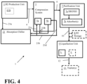
- Figures 2 , 3 , and 4 illustrate exemplary implementations of the embodiment of the apparatus shown in Figure 1 .
- the absorption chiller 21 is positioned to provide the cooling medium to cool compressed hydrogen gas output from the first compressor 5a (and/or provide inter-stage cooling for that first compressor 5a) via the first compressor cooling medium feed conduit 21c connected to the absorption chiller cooling medium output conduit 21b and also provide the cooling medium to the deoxygenation reactor aftercooler 7a via the purification unit heat exchanger cooling medium feed conduit 21e to cool the deoxygenated hydrogen gas output from the deoxygenation reactor of the purification unit 7.
- a warmed cooling medium return conduit 21R can be connected between the heat exchanger providing the first compressor cooling and the absorption chiller 21 and a warmed cooling medium return conduit 21R can be connected between the deoxygenation reactor aftercooler 7a and the absorption chiller 21 so that the warmed cooling medium output from those heat exchangers can be returned to the absorption chiller to be cooled back to the pre-selected chilling temperature.
- Figure 3 illustrates an exemplary implementation of the embodiment of the apparatus 1 shown in Figure 1 in which the absorption chiller 21 is positioned to provide the cooling medium to the deoxygenation reactor 7a via the purification unit heat exchanger cooling medium feed conduit 21e to cool the deoxygenated hydrogen gas output from the deoxygenation reactor of the purification unit 7.
- a warmed cooling medium return conduit 21R can be connected between the deoxygenation reactor aftercooler 7a and the absorption chiller 21 so that the warmed cooling medium output from the aftercooler 7a can be returned to the absorption chiller to be cooled back to the pre-selected chilling temperature.
- Figure 4 illustrates an exemplary implementation of the embodiment of the apparatus 1 shown in Figure 1 in which the absorption chiller 21 is positioned to provide the cooling medium for the compression system 5.
- the absorption chiller 21 is positioned to provide the cooling medium to cool compressed hydrogen gas output from the first compressor 5a (and/or provide inter-stage cooling for that first compressor 5a) via the first compressor cooling medium feed conduit 21c connected to the absorption chiller cooling medium output conduit 21b.
- the absorption chiller 21 is positioned to provide the cooling medium to cool compressed hydrogen gas output from the second compressor 5b (and/or provide inter-stage cooling for that second compressor 5b) via the second compressor cooling medium feed conduit 21d connected to the absorption chiller cooling medium output conduit 21b.
- a warmed cooling medium return conduit 21R can be connected between the heat exchanger providing the first compressor cooling and the absorption chiller 21 and a warmed cooling medium return conduit 21R can be connected between the heat exchanger for providing the second compressor cooling and the absorption chiller 21 so that the warmed cooling medium output from those heat exchangers can be returned to the absorption chiller 21 to be cooled back to the pre-selected chilling temperature.
- Embodiments of the absorption chiller 21 can be configured to utilize different absorption chiller arrangements.
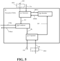
- Figure 5 illustrates an exemplary absorption chiller 21 that can be utilized in the above discussed embodiments of Figure 1 and exemplary implementations of Figures 2-4 , for example. Operation of embodiments of the absorption chiller 21 that can be utilized in embodiments of the apparatus 1 can also be appreciated from the discussion of absorption chiller operations provided in U.S. Patent Application Publication No. 2022/0099367 .
- the generator 22 of the absorption chiller 21 can receive at least one heated waste stream from the ammonia loop and/or hydrogen production unit 3 via at least one absorption chiller feed conduit 21a as discussed above.
- the generator 22 can utilize the heat from the heated waste stream(s) to form a high pressure concentrated solution HPCS to feed to the absorber 23a of the absorption chiller and also form a high-pressure refrigerant vapor RV for feeding to a condenser 23b of the absorption chiller.
- the condenser 23b can receive a condensing medium CMin to provide cooling to condense the refrigerant vapor RV for providing a low-pressure refrigerant liquid RL to an evaporator 24 of the absorption chiller 21.
- the warmed condensing medium CMout formed via its use in the condenser for condensing the high-pressure refrigerant vapor RV can be output from the condenser of the absorption chiller 21 as well.
- the condensing medium CMin can be from a chilled water supply and the warmed condensing medium CMout can be warmed water that can be output from the condenser for being fed to a chilled water return vessel.
- the condensing medium can alternatively be another fluid from another plant process or apparatus process element that can provide sufficient cooling to condense the high-pressure refrigerant vapor RV for forming the refrigerant liquid RL to be fed to the evaporator 24.
- the evaporator 24 of the absorption chiller 21 can utilize heat from the warmed cooling medium received via at least one warmed cooling medium return conduit 21R to evaporate the low-pressure refrigerant liquid RL to form a low pressure refrigerant vapor RV for feeding to the absorber of the absorption chiller 21.
- This operation can cool the warmed cooling medium to the pre-selected chilling temperature (which can also be referred to as the pre-selected cooling fluid temperature) so that the cooling medium can be output from the evaporator 24 of the absorption chiller 21 at the pre-selected chilling temperature via at least one absorption chiller cooling medium output conduit 21b.
- the absorber 23a of the absorption chiller 21 can receive the low-pressure refrigerant vapor RV from the evaporator 24 and the high pressure concentrated solution HPSC from the generator to output a high pressure diluted solution HPDS to the generator 22, which can be concentrated via the heat from the received waste stream(s) in the generator 22 for forming of the high pressure concentrated solution HPSC and high pressure refrigerant vapor RV.
- the solution used via the absorber 23a and generator 22 can be an ammonia-based solution, a lithium bromide (LiBr) solution, or other suitable solution.
- the cooling medium can be water (e.g ., chilling water) or another suitable cooling fluid (e.g. , a refrigerant, glycol, a mixture of water and glycol, etc.).
- the absorption chiller 21 can be positioned and configured so that the providing of the cooling medium can occur in a closed-loop arrangement. This can help minimize the need for cooling fluid. From time to time, a makeup amount of cooling medium can be added or fed to the absorption chiller via an absorption chiller cooling medium output conduit 21b or a warmed cooling medium return conduit 21R to account for any losses of the cooling medium that may occur at a relatively low rate from operations of the absorption chiller 21.
- the generator 22 can output a cooled waste stream 22H for being fed back to the hydrogen production unit 3 and/or ammonia loop of the ammonia manufacturing unit of an H2 Utilization Unit or H2 Conversion Unit 19.
- the output cooled waste stream can be further cooled via a generator waste stream heat exchanger HX1 (shown in broken line in Figure 5 ) to further cool that stream to a suitable temperature for recycling that stream back to the hydrogen production unit 3 or ammonia loop for subsequent use.
- a generator cooled waste stream heat exchanger HX1 shown in broken line in Figure 5
- Use of such a generator cooled waste stream heat exchanger HX1 can help further improve the operational efficiency associated with use of the absorption chiller 21.
- At least one warmed cooling medium return conduit 21R can include a warmed cooling medium heat exchanger HX2 (shown in broken line in Figure 5 ) to pre-cool or further heat the warmed cooling medium before it is fed to the evaporator 24.
- a warmed cooling medium heat exchanger HX2 shown in broken line in Figure 5
- Such a heat exchanger arrangement can be utilized when the warmed cooling medium passed through the warmed cooling medium return can provide cooling or heating to another process element of the apparatus 1, for example.
- Use of one or more warmed cooling medium heat exchangers HX2 for the warmed cooling medium can help further improve the operational efficiency associated with use of the cooling medium and absorption chiller 21.
- FIG. 6 illustrates an exemplary process that can be utilized in any of our above discussed embodiments of our apparatus 1.
- a heated waste stream of fluid e.g ., flue gas or steam from an ammonia loop, flue gas from an ammonia dissociator, heated water or steam from one or more electrolyzers, etc .
- a hydrogen production unit 3 e.g ., flue gas or steam from an ammonia loop, flue gas from an ammonia dissociator, heated water or steam from one or more electrolyzers, etc .
- the generator can form a coolant (e.g ., a refrigerant vapor) for feeding the coolant (e.g ., refrigerant) to an evaporator 24 for cooling a chilling medium (e.g ., chilling water, glycol, etc. ) for cooling (a) a flow of hydrogen of the compression system 5 (e.g.
- a coolant e.g ., a refrigerant vapor
- a chilling medium e.g ., chilling water, glycol, etc.
- a flow of hydrogen output form an element of a hydrogen purification unit 7 (e.g ., provide a cooling medium to a deoxygenation reactor aftercooler 7a), (c) a liquefaction pre-cooler 9a, and/or (d) a intercooling of the liquefaction unit 9.
- a hydrogen purification unit 7 e.g ., provide a cooling medium to a deoxygenation reactor aftercooler 7a
- a liquefaction pre-cooler 9a e.g ., provide a cooling medium to a deoxygenation reactor aftercooler 7a
- a liquefaction pre-cooler 9a e.g a liquefaction pre-cooler 9a
- the warmed chilling medium can be returned to the evaporator of the absorption chiller for chilling the chilling medium back to its pre-selected chilling temperature.
- the cooled waste fluid can be output from the generator 22 of the absorption chiller 21 to return that cooled waste fluid to the hydrogen production unit 3, ammonia loop of an ammonia manufacturing unit of an H2 Utilization Unit or H2 Conversion Unit 19 or other process element.
- the waste fluid can be disposed of in another suitable manner after the generator 22 utilizes heat from that fluid to help power the absorption chiller 21.
- embodiments of the process can include integrating an absorption chiller 21 into a plant to provide cooling medium flows to one or more plant process elements.
- embodiments of the process can also include designing and building a plant to include and use the absorption chiller 21 to use at least one waste stream from hydrogen production and/or ammonia manufacturing to provide one or more flows of a chilling medium for cooling one or more process elements (e.g. , compression system coolers, purification unit cooler(s), liquefaction pre-cooler and/or inter-cooler etc.).
- process elements e.g. , compression system coolers, purification unit cooler(s), liquefaction pre-cooler and/or inter-cooler etc.
- the power savings in kW can range from over 0 kW to 1,200 kW for some types of conventional systems.
- cooling provided via the deoxygenation reactor aftercooler 7a can facilitate a reduction in size of the adsorber(s).
- the cooling temperatures that can be provided can result in the adsorber inlet stream having a lower water content, which can help reduce the amount of adsorbent material (and thus size) of the adsorber(s) 7b that can be used.
- the cooling that can be provided via the feeding of the waste heat streams from the hydrogen production unit 3 to the generator of the absorption chiller can result in reducing gas cooler temperatures that may be used in some types of hydrogen production units in which electrolyzers can be used for forming hydrogen gas.
- the reduced gas cooler temperatures that can be provided can help facilitate a reduction in the amount of water make-up that can be needed for electrolysis in the electrolyzers, for example.
- a reduction of as much as 450 kg/h water can be provided in some embodiments in which electrolyzers may be used in the hydrogen production unit 3. In other embodiments, a reduction of as much 20% of water makeup can be provided.
- valves, piping, and other conduit elements e.g. , conduit connection mechanisms, tubing, seals, valves, etc .
- conduit connection mechanisms e.g., conduit connection mechanisms, tubing, seals, valves, etc .
- different elements e.g ., heat exchangers, storage devices, compressors, purification devices, etc .
- the flow rate, pressure, and temperature of the fluid passed through the various apparatus or system elements can vary to account for different design configurations and other design criteria.
- Embodiments of the apparatus for utilization of an absorption chiller for hydrogen production, process for utilization of an absorption chiller in hydrogen production, and/or system for utilization of an absorption chiller for hydrogen production can each be configured to include process control elements positioned and configured to monitor and control operations (e.g ., temperature and pressure sensors, flow sensors, an automated process control system having at least one work station that includes a processor, non-transitory memory and at least one transceiver for communications with the sensor elements, valves, and controllers for providing a user interface for an automated process control system that may be run at the work station and/or another computer device of the plant, etc. ).
- process control elements positioned and configured to monitor and control operations
- monitor and control operations e.g ., temperature and pressure sensors, flow sensors, an automated process control system having at least one work station that includes a processor, non-transitory memory and at least one transceiver for communications with the sensor elements, valves, and controllers for providing a user interface for an automated process control system that may be run at
Landscapes
- Engineering & Computer Science (AREA)
- Chemical & Material Sciences (AREA)
- Organic Chemistry (AREA)
- Physics & Mathematics (AREA)
- Mechanical Engineering (AREA)
- Thermal Sciences (AREA)
- General Engineering & Computer Science (AREA)
- Chemical Kinetics & Catalysis (AREA)
- Metallurgy (AREA)
- Electrochemistry (AREA)
- Inorganic Chemistry (AREA)
- Materials Engineering (AREA)
- Oil, Petroleum & Natural Gas (AREA)
- Combustion & Propulsion (AREA)
- Analytical Chemistry (AREA)
- General Chemical & Material Sciences (AREA)
- Environmental & Geological Engineering (AREA)
- Health & Medical Sciences (AREA)
- Biomedical Technology (AREA)
- Hydrogen, Water And Hydrids (AREA)
- Separation By Low-Temperature Treatments (AREA)
- Sorption Type Refrigeration Machines (AREA)
Applications Claiming Priority (1)
| Application Number | Priority Date | Filing Date | Title |
|---|---|---|---|
| US18/111,932 US20240279825A1 (en) | 2023-02-21 | 2023-02-21 | Apparatus and process for absorption chiller utilization for environmentally friendly hydrogen production |
Publications (2)
| Publication Number | Publication Date |
|---|---|
| EP4421433A2 true EP4421433A2 (de) | 2024-08-28 |
| EP4421433A3 EP4421433A3 (de) | 2025-01-22 |
Family
ID=89983706
Family Applications (1)
| Application Number | Title | Priority Date | Filing Date |
|---|---|---|---|
| EP24158108.1A Pending EP4421433A3 (de) | 2023-02-21 | 2024-02-16 | Vorrichtung und verfahren zur verwendung eines absorptionskühlers zur umweltfreundlichen wasserstoffherstellung |
Country Status (7)
| Country | Link |
|---|---|
| US (1) | US20240279825A1 (de) |
| EP (1) | EP4421433A3 (de) |
| CN (1) | CN118532883A (de) |
| AU (1) | AU2024201046B2 (de) |
| CA (1) | CA3229788A1 (de) |
| CL (1) | CL2024000464A1 (de) |
| MX (1) | MX2024002094A (de) |
Families Citing this family (1)
| Publication number | Priority date | Publication date | Assignee | Title |
|---|---|---|---|---|
| US12504203B2 (en) | 2023-02-10 | 2025-12-23 | EnhancedGEO Holdings, LLC | Reverse-flow magma-based geothermal generation |
Citations (8)
| Publication number | Priority date | Publication date | Assignee | Title |
|---|---|---|---|---|
| US7275569B2 (en) | 2003-07-03 | 2007-10-02 | Arizona Public Service Company | Hydrogen handling or dispensing system |
| US7438889B2 (en) | 2005-06-24 | 2008-10-21 | University Of South Carolina | Use of complex metal oxides in the autothermal generation of hydrogen |
| US7510696B2 (en) | 2005-02-07 | 2009-03-31 | Air Products And Chemicals, Inc. | Method and apparatus for the production of hydrogen-rich gas |
| EP3241805B1 (de) | 2016-05-06 | 2018-08-29 | Air Products And Chemicals, Inc. | Verfahren und vorrichtung zur herstellung eines wasserstoffhaltigen produkts |
| US20220033983A1 (en) | 2020-07-28 | 2022-02-03 | Air Products And Chemicals, Inc. | Method and apparatus for generating, storing and using hydrogen |
| US20220099367A1 (en) | 2020-09-29 | 2022-03-31 | Air Products And Chemicals, Inc. | Chiller, air separation system, and related methods |
| US20220397118A1 (en) | 2021-06-14 | 2022-12-15 | Air Products And Chemicals, Inc. | Process and apparatus for compressing hydrogen gas in a hybrid compression system |
| US20220397119A1 (en) | 2021-06-14 | 2022-12-15 | Air Products And Chemicals, Inc. | Method and apparatus for compressing a gas feed with a variable flow rate |
Family Cites Families (7)
| Publication number | Priority date | Publication date | Assignee | Title |
|---|---|---|---|---|
| JP2004210597A (ja) * | 2003-01-06 | 2004-07-29 | Toshiba Corp | 排熱利用水素・酸素システムおよび液体水素の製造方法 |
| EP3106435A1 (de) * | 2015-06-18 | 2016-12-21 | Casale SA | Verfahren zur modernisierung einer ammoniakanlage |
| US10788259B1 (en) * | 2015-12-04 | 2020-09-29 | Chester Lng, Llc | Modular, mobile and scalable LNG plant |
| AU2018285025B2 (en) * | 2017-06-16 | 2023-03-02 | Casale Sa | A plant, such as ammonia plant, comprising an absorption refrigeration unit |
| FR3086373B1 (fr) * | 2018-09-20 | 2020-12-11 | Air Liquide | Installation et procede d'epuration et de liquefaction de gaz naturel |
| EP4067533B1 (de) * | 2021-03-30 | 2026-03-18 | Linde GmbH | Verfahren und anlage zur elektrolytischen herstellung von flüssigwasserstoff |
| CN114214637B (zh) * | 2021-12-10 | 2024-06-25 | 四川蜀道装备科技股份有限公司 | 一种电解水制氢氧综合利用的装置和方法 |
-
2023
- 2023-02-21 US US18/111,932 patent/US20240279825A1/en active Pending
-
2024
- 2024-02-15 CL CL2024000464A patent/CL2024000464A1/es unknown
- 2024-02-15 MX MX2024002094A patent/MX2024002094A/es unknown
- 2024-02-16 EP EP24158108.1A patent/EP4421433A3/de active Pending
- 2024-02-18 CN CN202410180618.4A patent/CN118532883A/zh active Pending
- 2024-02-19 AU AU2024201046A patent/AU2024201046B2/en active Active
- 2024-02-21 CA CA3229788A patent/CA3229788A1/en active Pending
Patent Citations (8)
| Publication number | Priority date | Publication date | Assignee | Title |
|---|---|---|---|---|
| US7275569B2 (en) | 2003-07-03 | 2007-10-02 | Arizona Public Service Company | Hydrogen handling or dispensing system |
| US7510696B2 (en) | 2005-02-07 | 2009-03-31 | Air Products And Chemicals, Inc. | Method and apparatus for the production of hydrogen-rich gas |
| US7438889B2 (en) | 2005-06-24 | 2008-10-21 | University Of South Carolina | Use of complex metal oxides in the autothermal generation of hydrogen |
| EP3241805B1 (de) | 2016-05-06 | 2018-08-29 | Air Products And Chemicals, Inc. | Verfahren und vorrichtung zur herstellung eines wasserstoffhaltigen produkts |
| US20220033983A1 (en) | 2020-07-28 | 2022-02-03 | Air Products And Chemicals, Inc. | Method and apparatus for generating, storing and using hydrogen |
| US20220099367A1 (en) | 2020-09-29 | 2022-03-31 | Air Products And Chemicals, Inc. | Chiller, air separation system, and related methods |
| US20220397118A1 (en) | 2021-06-14 | 2022-12-15 | Air Products And Chemicals, Inc. | Process and apparatus for compressing hydrogen gas in a hybrid compression system |
| US20220397119A1 (en) | 2021-06-14 | 2022-12-15 | Air Products And Chemicals, Inc. | Method and apparatus for compressing a gas feed with a variable flow rate |
Also Published As
| Publication number | Publication date |
|---|---|
| CA3229788A1 (en) | 2025-04-15 |
| CN118532883A (zh) | 2024-08-23 |
| AU2024201046A1 (en) | 2024-09-05 |
| EP4421433A3 (de) | 2025-01-22 |
| US20240279825A1 (en) | 2024-08-22 |
| MX2024002094A (es) | 2024-08-22 |
| CL2024000464A1 (es) | 2024-09-06 |
| AU2024201046B2 (en) | 2026-02-19 |
Similar Documents
| Publication | Publication Date | Title |
|---|---|---|
| US10816262B2 (en) | Production equipment and production method of liquefied hydrogen and liquefied natural gas | |
| EP4365526A1 (de) | Wasserstoffverflüssigungssystem | |
| EP4421433A2 (de) | Vorrichtung und verfahren zur verwendung eines absorptionskühlers zur umweltfreundlichen wasserstoffherstellung | |
| JP4429552B2 (ja) | 液体水素の製造システム | |
| CN101818853B (zh) | 带冷量利用的循环吸附储氢装置 | |
| JP2023548010A (ja) | 極低温で水素を製造するためのプラント及び方法 | |
| EP4513118A1 (de) | Modulares wasserstoffverflüssigungssystem | |
| CN204240703U (zh) | 一种利用液化天然气冷能的高效空分装置 | |
| KR20230104898A (ko) | 극저온에서 수소를 생성하기 위한 설비 및 방법 | |
| CN119222487B (zh) | 一种回收液氢冷能的高压气氢液氢联合加注系统及方法 | |
| US20240361071A1 (en) | Systems and methods for hydrogen liquefaction | |
| US20250060155A1 (en) | Apparatus and Process for Pre-Liquefaction Fluid Processing for Improved Liquefaction Operations | |
| CN116255790A (zh) | 一种用于制备液氢的预冷循环系统及方法 | |
| KR102939248B1 (ko) | 암모니아 냉열을 활용한 수소 압축 시스템 | |
| BR102024003026A2 (pt) | Aparelho e processo para utilização de resfriador de absorção para produção de hidrogênio ambientalmente amigável | |
| CN116951904B (zh) | 一种耦合lng冷能的空气分离装置与氢液化预冷装置的联合系统 | |
| CN116592574B (zh) | 一种回收膨胀功的液氢运输船再液化系统 | |
| CN116857900B (zh) | 一种工业尾气提纯液化二氧化碳的方法与装置 | |
| US20240369293A1 (en) | Apparatus and process for oxygen recovery | |
| CN116951903B (zh) | 一种基于氮气循环制冷的空分与氢液化预冷联合系统 | |
| CN214620293U (zh) | 一种煤层气液化系统 | |
| CN220981733U (zh) | 氢气液化系统 | |
| KR20240033997A (ko) | 액화천연가스의 냉열 에너지를 이용한 수소 액화 설비 및 이를 구비하는 액체 수소 생산 시스템 | |
| KR20260032989A (ko) | 극저온 유체 생산 설비 및 방법 | |
| CN121346464A (zh) | 一种氮节流膨胀co泵加压脱氢制备高压co的装置及方法 |
Legal Events
| Date | Code | Title | Description |
|---|---|---|---|
| PUAI | Public reference made under article 153(3) epc to a published international application that has entered the european phase |
Free format text: ORIGINAL CODE: 0009012 |
|
| STAA | Information on the status of an ep patent application or granted ep patent |
Free format text: STATUS: THE APPLICATION HAS BEEN PUBLISHED |
|
| AK | Designated contracting states |
Kind code of ref document: A2 Designated state(s): AL AT BE BG CH CY CZ DE DK EE ES FI FR GB GR HR HU IE IS IT LI LT LU LV MC ME MK MT NL NO PL PT RO RS SE SI SK SM TR |
|
| PUAL | Search report despatched |
Free format text: ORIGINAL CODE: 0009013 |
|
| AK | Designated contracting states |
Kind code of ref document: A3 Designated state(s): AL AT BE BG CH CY CZ DE DK EE ES FI FR GB GR HR HU IE IS IT LI LT LU LV MC ME MK MT NL NO PL PT RO RS SE SI SK SM TR |
|
| RIC1 | Information provided on ipc code assigned before grant |
Ipc: F25J 1/00 20060101AFI20241219BHEP |
|
| STAA | Information on the status of an ep patent application or granted ep patent |
Free format text: STATUS: REQUEST FOR EXAMINATION WAS MADE |
|
| 17P | Request for examination filed |
Effective date: 20250722 |
|
| RAV | Requested validation state of the european patent: fee paid |
Extension state: MA Effective date: 20250722 |