EP4421425A1 - Covering system for a horizontal refrigerated counter, as well as covering for refrigerated counter and method for manufacturing thereof - Google Patents
Covering system for a horizontal refrigerated counter, as well as covering for refrigerated counter and method for manufacturing thereof Download PDFInfo
- Publication number
- EP4421425A1 EP4421425A1 EP24159688.1A EP24159688A EP4421425A1 EP 4421425 A1 EP4421425 A1 EP 4421425A1 EP 24159688 A EP24159688 A EP 24159688A EP 4421425 A1 EP4421425 A1 EP 4421425A1
- Authority
- EP
- European Patent Office
- Prior art keywords
- pair
- profiles
- glass sheet
- section
- sheet
- Prior art date
- Legal status (The legal status is an assumption and is not a legal conclusion. Google has not performed a legal analysis and makes no representation as to the accuracy of the status listed.)
- Granted
Links
Images

Classifications
-
- F—MECHANICAL ENGINEERING; LIGHTING; HEATING; WEAPONS; BLASTING
- F25—REFRIGERATION OR COOLING; COMBINED HEATING AND REFRIGERATION SYSTEMS; HEAT PUMP SYSTEMS; MANUFACTURE OR STORAGE OF ICE; LIQUEFACTION SOLIDIFICATION OF GASES
- F25D—REFRIGERATORS; COLD ROOMS; ICE-BOXES; COOLING OR FREEZING APPARATUS NOT OTHERWISE PROVIDED FOR
- F25D23/00—General constructional features
- F25D23/02—Doors; Covers
- F25D23/026—Doors; Covers for open-top cabinets
-
- A—HUMAN NECESSITIES
- A47—FURNITURE; DOMESTIC ARTICLES OR APPLIANCES; COFFEE MILLS; SPICE MILLS; SUCTION CLEANERS IN GENERAL
- A47F—SPECIAL FURNITURE, FITTINGS, OR ACCESSORIES FOR SHOPS, STOREHOUSES, BARS, RESTAURANTS OR THE LIKE; PAYING COUNTERS
- A47F3/00—Show cases or show cabinets
- A47F3/04—Show cases or show cabinets air-conditioned, refrigerated
- A47F3/0404—Cases or cabinets of the closed type
- A47F3/0426—Details
- A47F3/0434—Glass or transparent panels
-
- F—MECHANICAL ENGINEERING; LIGHTING; HEATING; WEAPONS; BLASTING
- F25—REFRIGERATION OR COOLING; COMBINED HEATING AND REFRIGERATION SYSTEMS; HEAT PUMP SYSTEMS; MANUFACTURE OR STORAGE OF ICE; LIQUEFACTION SOLIDIFICATION OF GASES
- F25D—REFRIGERATORS; COLD ROOMS; ICE-BOXES; COOLING OR FREEZING APPARATUS NOT OTHERWISE PROVIDED FOR
- F25D23/00—General constructional features
- F25D23/02—Doors; Covers
- F25D23/021—Sliding doors
-
- F—MECHANICAL ENGINEERING; LIGHTING; HEATING; WEAPONS; BLASTING
- F25—REFRIGERATION OR COOLING; COMBINED HEATING AND REFRIGERATION SYSTEMS; HEAT PUMP SYSTEMS; MANUFACTURE OR STORAGE OF ICE; LIQUEFACTION SOLIDIFICATION OF GASES
- F25D—REFRIGERATORS; COLD ROOMS; ICE-BOXES; COOLING OR FREEZING APPARATUS NOT OTHERWISE PROVIDED FOR
- F25D2400/00—General features of, or devices for refrigerators, cold rooms, ice-boxes, or for cooling or freezing apparatus not covered by any other subclass
- F25D2400/10—Refrigerator top-coolers
Definitions
- the present invention relates to the technical field of horizontal well refrigerator counters and in particular it relates to a system for providing the cover for a refrigerated counter and a refrigerated counter comprising such covering system. Furthermore, the invention relates to a method for providing a cover of a refrigerated counter.
- the horizontal well refrigerated counters generally comprise a substantially parallelepiped shaped base and an upper cover.
- refrigerated counters comprise an upper cover made of glass.
- the refrigerated counter has a pleasant aesthetic appearance.
- covers provide for slidable glasses so as to allow the user access to the contents in the counter.
- those comprising curved glasses are particularly valued due to their high aesthetic appeal.
- the known systems for providing such type of cover comprise a plurality of arched and superimposed lateral guides designed to guide the rotation of the curved glasses on opposite sides.
- Such systems can be improved on various aspects, with particular reference to the aesthetic appeal, safety for the users, manufacturing costs as well as the ease of assembly.
- the assembly method is particularly long and complicated given that there arises the need to keep the glass sheets during the installation steps.
- the object of the present invention is to overcome the drawbacks outlined above by providing a covering system for refrigerated counters that is highly effective and relatively cost-effective.
- a further object of the present invention is to provide a covering system for refrigerated counters that is particularly versatile.
- a further object of the present invention is to provide a covering system for refrigerated counters that has high aesthetic appeal.
- a further object of the present invention is to provide a covering system for refrigerated counters that is simple and quick to assemble;
- a further object of the present invention is to provide a covering system for refrigerated counters that is simple to manufacture
- a further object of the present invention is to provide a method for manufacturing the cover of refrigerated counter that is highly effective and relatively cost-effective.
- a further object of the present invention is to provide cover for a refrigerated counter that is highly effective and relatively cost-effective.
- a cover 10 to be used in refrigerated counters 1 of the horizontal well type is a cover 10 to be used in refrigerated counters 1 of the horizontal well type.
- the cover 10 of the present invention will be particularly suitable for use in refrigerated counters of the type with remote motor.
- the refrigerated counter 1 may be a remote island.
- the refrigerated counter 1 may comprise a base 2 and the cover 10.
- the base 2 may have a substantially parallelepiped shape and it may therefore comprise a lower area 3 designed to come into contact with the floor and an upper area 4 with an upper edge 5.
- the edge 5 may support the cover 10.
- the refrigerated counter 1 may have different sizes while maintaining its substantially rectangular shape in plan view.
- the cover 10 may be modular.
- a system 11 for providing the cover 10 which may comprise a plurality of parts which can be coupled to each other.
- the system 11 may be modular.
- the cover 10 may be at least partially or entirely transparent.
- At least one glass sheet 50 movable between a closed position in which it prevents access into the refrigerated counter 1 and an open position in which it allows access thereinto.
- a handle may be provided for in a per se known manner to move the glass sheet 50.
- the glass sheet 50 may comprise at least one planar portion 51 and at least one curved portion 52.
- the glass sheet 50 may consist of such planar 51 and curved 52 portion.
- planar portion 51 may define a plane ⁇ .
- the latter may be substantially parallel to the floor in use.
- the cover 10 may have a main extension in such plane ⁇ or parallel thereto.
- the expression main extension is used to indicate that the horizontal size, that is along such plane ⁇ or parallel thereto, may be significantly greater than the vertical size, that is orthogonal to such plane ⁇ .
- such plane ⁇ may be parallel to the edge 5 and, even more preferably, it may be parallel and spaced apart therefrom.
- the height of the cover 10 may be substantially equal to the height of the curved portion 52. Such height may correspond to the distance between the plane ⁇ and the edge 5.
- such height may be about 10-15 cm.
- edge 5 corresponds to the so-called "loading line”.
- the flat portions of the glass sheets may be spaced apart from the loading line avoiding the formation of condensate on the glasses, as it instead happens with glass sheets which slide in proximity of the loading line.
- such configuration of the glass sheet 50 with the curved portion 52 may allow to obtain a high aesthetic appeal.
- the handle may be arranged at such curved portion 52 therefore being easy to operate for the operator.
- the glass sheet 50 may therefore slide along a direction d lying on the plane ⁇ or substantially parallel to the latter. In this manner, advantageously, the user may open and close the counter 1 by sliding the glass sheet 50 along such sliding direction d.
- the direction d may be substantially parallel to the floor in which the refrigerated counter is positioned.
- the system 11 may comprise at least one pair of support profiles 20.
- the profiles 20 may support the glass sheet 50 or the glass sheets 50.
- each of the profiles 20 may have at least one substantially straight section 21 defining a respective axis X, X'.
- axes X, X' may lie on the plane ⁇ or in a plane substantially parallel thereto.
- the profiles 20 may further comprise at least one substantially curvilinear section 22. Possibly, as better explained hereinafter, they may comprise two curved sections 22, 23 arranged on opposite sides with respect to the straight section 21. Each profile 20 may therefore be substantially arc-shaped with a central straight section 21.
- the profiles 20 may be operatively fixed with the base 2.
- the profiles 20 may be fixed with the peripheral edge 5 of the base 2, preferably at a pair of opposite sections of the peripheral edge 5.
- the profiles 20 may be fixed on one side with the edge 5 and on the other to a support profile which may preferably be a support profile 20.
- the profiles 20 may be fixed with the edge 5 at an end 22', 23' of the curved sections 22, 23.
- Such fixing may be obtained in a per se known manner, for example using plates and screws.
- the latter may remain substantially parallel and facing each other.
- the system 11 may comprise a pair or a higher number of profiles 20. Furthermore, the system 11 may comprise a single slidable sheet 50 or a plurality of the latter.
- the same profile 20 may have the function of supporting the movable sheet 50 and supporting one or more further support profiles 20. This allows to obtain a modular cover 10.
- the pair of profiles 20 may each have a single curved section 22 fixed to the edge 5 and an end 21' of the section 21 fixed to a section 21 of another profile 20.
- FIG. 1 shows a cover 10 which comprises a first pair of glass sheets 50 slidable along the same direction d in opposite directions, and another single glass sheet 50 slidable in a direction d perpendicular to the sliding direction d of the first pair of sheets 50.
- the system 11 may comprise a plurality of pairs of glass sheets 50 all arranged adjacent to each other. Such configuration may be particularly adapted for providing refrigerated counters having a particularly large longitudinal extension found in supermarkets.
- each profile 20 may support two pairs of sheets 50 arranged on opposite sides.
- the system 11 may allow to obtain covers 10 having a different extension. In this manner, the system 11 is particularly versatile and cost-effective at the same time.
- the sliding direction d of the glass sheets 50 may be parallel to the axes X and X' of the sections 21 of the support profiles 20 which support the sheet.
- the planar portion 51 when the sheet 50 is in closed position, the planar portion 51 may be at the straight section 21 and the curved portion 52 may be at the curved section 22, 23 of the pair of support profiles 20.
- the curved portion 52 may be at the straight section 21. In this case, therefore an opening will be formed between the edge 5 and the curved portion 52 to allow access into the refrigerated counter 1.
- the system 11 may comprise guide elements 30 to guide the sliding of the sheet 50 between the open and closed positions along the direction d, that is along a substantially straight direction.
- the guide elements 30 may be at least one pair of elements arranged facing each other. Therefore, they may guide the sliding of the sheet 50 on opposite sides.
- the elements 30 may be operatively coupled with the profiles 20
- the elements 30 may be operatively coupled with the profiles 20 at the straight section 21.
- the section 21 may be shaped so as to define the elements 30.
- the glass sheet 50 may comprise at least one pair of slider elements 25.
- the planar portion 51 of the sheet 50 may comprise the slider elements 25.
- the guide elements 30 and the slider elements 25 may be mutually configured to guide the sliding of the glass sheet 50 along the direction d between the closed and open position.
- the guide elements 30 may therefore guide the sliding of the slider elements 25 along the direction d or a direction parallel to the direction d.
- the guide elements 30 may be configured to guide the slider elements 25 alone. More particularly, the guide elements 30 may be configured to interact with the slider elements 25 and/or with the flat portion 51, and at the same time so as not to interact with the curved portion 52.
- This characteristic may allow to prevent the elements 30 from hindering the sliding of the sheet 50 along the direction d.
- the planar portion 51 may have a pair of opposite lateral edge areas 55 which may define the pair of slider elements 25.
- the creation and the assembly of the system may be particularly simple. As a matter of fact, the operator may simply pick up the sheet and insert it frontally between the guide elements 30.
- the section 21 may support the slider elements 25 to slidably guide them along the axes X and X'.
- the guide elements 30 may comprise such section 21.
- the guide elements 30 may comprise at least one pair of substantially planar surfaces having extension along respective longitudinal axes parallel to the plane ⁇ designed to support the sliders 25 to slidably guide them.
- the guide elements 30 may comprise a pair of longitudinal surfaces 32.
- the latter may define the axes X and X'.
- the surfaces 32 may have a planar extension substantially parallel to or coincident with the plane ⁇ .
- the system 11 may be particularly simple to install given that there may be substantially used a plurality of profiles 20.
- the surfaces 32 may guide the sliding of the slider elements 25 and at the same time support the latter and therefore the glass sheet 50.
- the profiles 20 may act as a support and guide for the sheets 50.
- the surfaces 32 and the glass sheet 50 may be mutually sized so that during the movement of the glass sheet 50 between the open and closed position, the longitudinal surfaces 32 interact with the planar portion 51, and so that the longitudinal surfaces 32 do not interact with the curved portion 52.
- only the slider elements 25 may interact with the longitudinal surfaces 32.
- the lateral areas 55 of the planar portion 51 may interact with the surface 32 so that the latter guides the sliding thereof and supports the weight of the sheet 50.
- the lateral areas 55 may come into direct contact with the surface 32.
- the surfaces 32 may have an overall length-wise extension along the axes X and X' equal to the length of the planar portion 51.
- the surfaces 32 may have a smaller length or they may be discontinuous.
- the longitudinal planar surface 32 may have a particularly small width L3, for example measuring approximately 1 or 2 cm, preferably measuring about 10-12 mm.
- the distance A between the opposite guide elements 30 of a pair of profiles 20 may be slightly larger than the width L2, that is the width of the curved portion 52. Furthermore, advantageously, the distance A may be slightly smaller than the width L1 that is than the distance between the ends of the slider 25.
- the width L1 may be 1300 mm
- the width L2 may be 1280 mm
- the distance A may be comprised between L1 and L2.
- the distance A may be only slightly larger than L2, for example by a few millimetres, so that the contact of the sliders 25 on the surface 32 is maximum.
- the width L1 may be the width of the planar portion 51 of the sheet 50.
- the distance A may be the distance between the two surfaces 32.
- the portion 51 may always be guided by the surfaces 32 during the sliding between the open and closed position, that is even when the curved portion 52 is at the surfaces 32.
- the sheet 50 may always be supported. Therefore, it is not necessary to use special machines or a large number of operators during the installation.
- the glass sheet 50 may have a step 53, preferably a pair of steps 53.
- the step 53 may measure about 10-12 mm. Such value may correspond to half of the difference between the widths L1 and L2. For example, should there be the sliders 55 and the surfaces 32, the difference between the width L1 of the portion 51 and the width L2 of the portion 52 may measure about 20-24 mm.
- the planar portion 51 may comprise such step 53.
- the curved portion 52 may be downstream of the step 53 considering the direction from the open position to the closed position.
- the processing of the sheet 50 may be simple and cost-effective.
- the profiles 20 may include the guide elements 30.
- the section 21 may comprise the guide elements 30. More preferably, as shown in the attached figures, the sections 21 of the profile 20 may comprise or define the surfaces 32.
- the section 21 may comprise a longitudinal wall 36.
- the wall 36 may remain substantially horizontal while the wall 37 may remain substantially vertical.
- the longitudinal wall 36 may include an upper surface defining the longitudinal support surface 32.
- the section 21 may further comprise a wall 37 orthogonal to the wall 36.
- a wall 37 may guide the sliding of the sliders 25, for example of the edge 55 of the portion 51.
- the wall 37 may come into contact with the sliders 25, for example the edge areas 55 of the flat portion 51 of the sheet 50, so as to avoid the sliding of the sheet 50 along a direction transversal to the axes X or X' and therefore ensure the sliding along the direction d.
- the distance between the walls 37 of two opposite profiles 20 may be substantially equal to the width L1.
- the guide elements 30 may therefore comprise the wall 37.
- the wall 37 may cooperate with the longitudinal surface 32 to guide the sliding of the edge 55.
- the walls 36 and 37 may cooperate to define a longitudinal seat 31.
- the guide elements 30 may therefore comprise such seat 31.
- the section 21 may therefore comprise at least one upper longitudinal wall 39 which may remain arranged substantially facing the lower wall 36.
- such wall 37 may guide the sliding of the sliders 25, for example of the edge 55 of the portion 51.
- such wall 39 may retain the slider 25 and/or the edge 55 to prevent it from lifting during the sliding of the sheet 50.
- the guide elements 30 may therefore comprise the wall 39.
- the walls 39 and 36 may cooperate to form the longitudinal seat 31.
- the walls 37, 39 and 36 may cooperate to form the substantially C-shaped longitudinal seat 31.
- the guide elements 30, which may comprise such seat 31, may ensure the sliding of the sheet 50 along the direction d.
- the support surface 32 may be defined by a plurality of surfaces, not necessarily by a single continuous longitudinal surface.
- the support surface 32 may be defined by a plurality of surfaces, not necessarily by a single continuous longitudinal surface.
- the glass sheet 50 may be slidably inserted along the direction d thanks to the guide elements 30.
- the sheet 50 may be inserted frontally and there is no need for using men or means to support and hold it in position during the assembly.
- At least one pair of substantially curved profiles 70 may be coupled with the profiles 20.
- the profiles 70 may be coupled with the section 22 and/or 23 of the section 20.
- the profiles 70 may therefore act as an abutment for the portion 52 of the sheet 50 defining the closed position of the latter.
- the profiles 70 may comprise a longitudinal abutment surface 71 designed to act as an abutment for at least one part of the portion 52 of the sheet 50.
- the profiles 70 may have an aesthetic function.
- the profiles 70 may comprise a substantially continuous outer surface 78.
- the outer surface 78 may be substantially equal to the outer surface 38 of the section 21.
- the section 21 and the section 22, once covered with the profile 70 may be substantially continuous and the outer surfaces 38, 78 may cooperate to form a single substantially continuous outer surface of the profile 20.
- the profile 20 may be formed by more pieces.
- the profiles 27 may be coupled at one end 21' of the section 21.
- the provision of the system 11 may be particularly cost-effective.
- the profile 20 may comprise the section 21 and two curved profiles 27 to form the sections 22 and 23.
- the profile 20 may comprise the section 21 and a single curved profile 27 defining the section 22 (or 23 ).
- the system may be particularly versatile.
- a single shaped profile 28 which may comprise a pair of curved portions 28' and a substantially straight portion 29 for connecting the curved portions 28'.
- the shaped profile 28 may cooperate so that the curved portions 28' define the respective section 22 (or the section 23 ) of the pair of profiles 20.
- the shaped profile 28 may be coupled with the straight sections 21.
- the curved portions 28' may be coupled with the ends 21' of two sections 21 - arranged facing each other - of a pair of profiles 20.
- the assembly may be particularly simple.
- the framework thus made may be particularly resistant.
- the system 11 may further comprise a further covering profile 60 designed to be arranged at the edge 5 and at the edge end 54 of the portion 52 of the glass sheet 50.
- the edge 54 may be the horizontal vacant edge, that is substantially perpendicular to the advancement direction.
- the profile 60 may be snap-coupled with the edge 5 in a per se known manner.
- the profile 60 may extend over the entire edge 54 between the pair of profiles 20.
- the profile 60 may have a cover function so as to confer a high aesthetic appeal to the system 11.
- the profile 60 may have a cover function and it may be coupled to such shaped profile 28.
- all the outer surfaces, that is the exposed surfaces, may have a pleasant and continuous appearance so as to confer a high aesthetic appeal to the entire system 11.
- the profile 60 may act as an abutment for the glass sheet 50 defining the closed position.
- the profile 60 and the surface 71 may cooperate to define the end-of-stroke of the sheet 50, that is the closed position.
- the profiles 20 and/or 60 and/or 70 may be partially or fully made of polymeric material. Possibly, such material may be soft so as to provide the closing sealing.
- a further flat sheet 40 may be provided for a further flat sheet 40.
- Such sheet 40 may be positioned at the section 21.
- the sheet may be positioned at the outer surface 38 of the section 21. More preferably, the sheet 40 may be fixed to the outer surface 38.
- the sheet 40 may be in a parallel plane and spaced apart with respect to the plane ⁇ of the portion 51 of the sheet 50. In this manner, the sheet 50 may slide between the closed position and the open position remaining below the sheet 40.
- the sheet 40 may be used to support products, label holder or the like.
- the section 21 may comprise a longitudinal protuberance 34 extending from the wall 39 orthogonally thereto.
- the protuberance 34 may therefore define a lateral abutment for the sheets 40.
- the upper surface 38 may support the glass sheet 40. More preferably, the height of the protuberance 34 may be substantially equal to or slightly larger than the thickness of the glass sheet 40. This characteristic may allow to protect the glass sheet 40 against possible impacts and/or there may be a visual continuity which results in a high aesthetic appeal of the cover 10.
- the system 11 may comprise more than one slidable sheet 50.
- the elements 30 may be configured to guide both sheets 50.
- the section 21 may comprise a pair of parallel and superimposed surfaces 32.
- stop elements 31' of the per se known type so as to prevent sheet 50 - when opened - from impacting against the other sheet 50.
- the same profile 20 may support two opposite sheets 50 (that is that slide along opposite directions of the same direction d ).
- the pair of slidable sheets 50 may be equal to each other. Such characteristic allows to optimise the production costs and times of the system 11.
- the profile 20 may comprise the straight central section 21 and a pair of curved sections 22, 23 on opposite sides so that the profile 20 is substantially arc-shaped.
- the section 21 may comprise a pair of guide elements 30 on opposite sides so that each one of the latter may guide an adjacent sheet 50.
- the two adjacent sheets 50 may slide along directions d substantially parallel to each other.
- the section 21 may have a pair of opposite longitudinal surfaces 32, more preferably the section 21 may have a pair of opposite seats 31.
- the same profile 20 may support two adjacent sheets 50 (sliding along parallel directions d ).
- the same profile 20 may support two adjacent sheets 50 and two opposite sheets 50.
- the section 21 may comprise two superimposed seats 31 - on one side - and two superimposed seats 31, on the opposite side.
- a sheet 50 slidable along a direction d and at least one sheet slidable along a direction d perpendicular to the first may be possibly provided for.
- the profile may comprise the section 21, whose end 21' may be coupled to a section 21 of another profile 20 having a perpendicular extension, and a single curved profile 27 defining the section 22 (or 23 ) which may be coupled - on one end - with the edge 5 and - with the other end - to another section 21.
- glass sheets 80 preferably curved glass sheets which may be interposed between the profiles 20 and the edges 5, for example as shown in FIG. 5 .
- the method for assembling the cover may provide for one or more of the following steps:
- the assembly may be frontal and the sheet 50 may be supported by the support profiles 20 with the advantages described above in terms of speed of assembly and saving in terms of men or means.
- the assembly method may comprise the steps for providing the profiles 27 and 28 and coupling them with the section 21 to form curved sections 22 and 23 of the profiles 20.
- the glass sheet 50 may be inserted into the guide elements 30 so that the sheet 50 is supported by the frame.
- the frame may be made with different configuration depending on the needs.
- the glass sheets 50 may be inserted.
- abutment profiles operatively coupled with the frame. In other words, they may define the end-of-stroke of the closed position.
- the profiles 70 and/or the profiles 60 may act as an abutment for the glass sheet 50, preferably for the curved portion 52 thereof.
- the assembly method may comprise the steps for preparing a pair of curved cover profiles 70 and coupling of the latter with the curved section 22 and 23. There may also be provided for a step for providing the profile 60 and coupling thereof with the shaped profile 28.
- a step for providing the sheet 40 and fixing it to the section 21 may also be provided for a step for providing the sheet 40 and fixing it to the section 21. Such step may be provided before the insertion of the sheets 50 into the guide elements 30.
- the assembly of the cover may be particularly simple and quick.
- the described modularity may allow to repeat such steps for providing covers 10 having a plurality of slidable sheets 50, for example as shown in FIG. 1 .
Landscapes
- Engineering & Computer Science (AREA)
- Physics & Mathematics (AREA)
- Thermal Sciences (AREA)
- Chemical & Material Sciences (AREA)
- Combustion & Propulsion (AREA)
- Mechanical Engineering (AREA)
- General Engineering & Computer Science (AREA)
- Refrigerator Housings (AREA)
Abstract
Description
- The present invention relates to the technical field of horizontal well refrigerator counters and in particular it relates to a system for providing the cover for a refrigerated counter and a refrigerated counter comprising such covering system. Furthermore, the invention relates to a method for providing a cover of a refrigerated counter.
- The horizontal well refrigerated counters generally comprise a substantially parallelepiped shaped base and an upper cover. Among the various types, particularly valued are those in which refrigerated counters comprise an upper cover made of glass.
- In this manner, on the one hand the users may see the contents of the counter without opening the cover and, on the other hand, the refrigerated counter has a pleasant aesthetic appearance. Such covers provide for slidable glasses so as to allow the user access to the contents in the counter.
- Among glass covers, those comprising curved glasses are particularly valued due to their high aesthetic appeal.
- The known systems for providing such type of cover comprise a plurality of arched and superimposed lateral guides designed to guide the rotation of the curved glasses on opposite sides.
- Such systems can be improved on various aspects, with particular reference to the aesthetic appeal, safety for the users, manufacturing costs as well as the ease of assembly.
- For example, the assembly method is particularly long and complicated given that there arises the need to keep the glass sheets during the installation steps. As a matter of fact, to mount such covering systems, there arises the need to fix a first lateral guide to the base, insert into the guide the edge of a curved glass sheet, maintain the curved glass sheet in such position, provide the second lateral guide and insert it on the opposite edge of the glass sheet and then fix the second guide to the base.
- The object of the present invention is to overcome the drawbacks outlined above by providing a covering system for refrigerated counters that is highly effective and relatively cost-effective.
- A further object of the present invention is to provide a covering system for refrigerated counters that is particularly versatile.
- A further object of the present invention is to provide a covering system for refrigerated counters that has high aesthetic appeal.
- A further object of the present invention is to provide a covering system for refrigerated counters that is simple and quick to assemble;
- A further object of the present invention is to provide a covering system for refrigerated counters that is simple to manufacture;
- A further object of the present invention is to provide a method for manufacturing the cover of refrigerated counter that is highly effective and relatively cost-effective.
- A further object of the present invention is to provide cover for a refrigerated counter that is highly effective and relatively cost-effective.
- These and other objects which will be more apparent hereinafter, are attained by the covering system for a refrigerated counter and/or a method for manufacturing the cover for refrigerated counter and/or a cover for refrigerated counters and/or a refrigerated counter as described and/or claimed and/or illustrated herein.
- The dependent claims relate to advantageous embodiments of the invention.
- Further characteristics and advantages of the invention will be more apparent in light of the detailed description of some preferred but non-exclusive embodiments of the invention, illustrated by way of non-limiting example with reference to the attached drawings, wherein:
-
FIG. 1 is a view of an example of a horizontal well refrigerated counter 1 with abase 2 and acover 10; -
FIG. 2 is a schematic view of some details of thecover 10; -
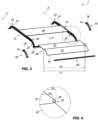
FIG. 3 is an exploded view of some details of thecover 10 comprising aflat glass sheet 40 and acurved glass sheet 50; -
FIG. 4 is an enlarged view of some details ofFIG. 3 ; -
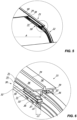
FIG. 5 is an enlarged view of some details ofFIG. 3 , with inFIG. 6 an enlarged view of some details ofFIG. 5 . - With reference to the attached figures, herein described is a
cover 10 to be used in refrigerated counters 1 of the horizontal well type. In particular, thecover 10 of the present invention will be particularly suitable for use in refrigerated counters of the type with remote motor. For example, the refrigerated counter 1 may be a remote island. - In any case, the refrigerated counter 1 may comprise a
base 2 and thecover 10. - In particular, the
base 2 may have a substantially parallelepiped shape and it may therefore comprise alower area 3 designed to come into contact with the floor and anupper area 4 with an upper edge 5. In greater detail, the edge 5 may support thecover 10. - The refrigerated counter 1 may have different sizes while maintaining its substantially rectangular shape in plan view. As a matter of fact, as better explained hereinafter, the
cover 10 may be modular. - Described below is a system 11 for providing the
cover 10 which may comprise a plurality of parts which can be coupled to each other. In other words, the system 11 may be modular. - The
cover 10 may be at least partially or entirely transparent. - Suitably there may therefore be provided for at least one
glass sheet 50 movable between a closed position in which it prevents access into the refrigerated counter 1 and an open position in which it allows access thereinto. - It is clear that a handle may be provided for in a per se known manner to move the
glass sheet 50. - According to a particular aspect of the invention, the
glass sheet 50 may comprise at least oneplanar portion 51 and at least onecurved portion 52. Preferably, theglass sheet 50 may consist of such planar 51 and curved 52 portion. - In particular, the
planar portion 51 may define a plane π. The latter may be substantially parallel to the floor in use. - In general, the
cover 10 may have a main extension in such plane π or parallel thereto. The expression main extension is used to indicate that the horizontal size, that is along such plane π or parallel thereto, may be significantly greater than the vertical size, that is orthogonal to such plane π. - Preferably, in use, such plane π may be parallel to the edge 5 and, even more preferably, it may be parallel and spaced apart therefrom.
- Suitably, the height of the
cover 10 may be substantially equal to the height of thecurved portion 52. Such height may correspond to the distance between the plane π and the edge 5. - For example, such height may be about 10-15 cm.
- Generally, the edge 5 corresponds to the so-called "loading line".
- Advantageously, this will allow to prevent the contents of the refrigerated counter from "rubbing" with the
flat part 51 of theslidable glass sheet 50. Such drawback is known in known covers obtained with slidable-plane glass sheets. - Furthermore, the flat portions of the glass sheets, that is the
portion 51 and also thesheet 40 if present, may be spaced apart from the loading line avoiding the formation of condensate on the glasses, as it instead happens with glass sheets which slide in proximity of the loading line. - Furthermore, such configuration of the
glass sheet 50 with thecurved portion 52 may allow to obtain a high aesthetic appeal. - Lastly, the handle may be arranged at such
curved portion 52 therefore being easy to operate for the operator. - The
glass sheet 50 may therefore slide along a direction d lying on the plane π or substantially parallel to the latter. In this manner, advantageously, the user may open and close the counter 1 by sliding theglass sheet 50 along such sliding direction d. Actually, the direction d may be substantially parallel to the floor in which the refrigerated counter is positioned. - Essentially, the system 11 may comprise at least one pair of
support profiles 20. In particular, theprofiles 20 may support theglass sheet 50 or theglass sheets 50. - In greater detail, each of the
profiles 20 may have at least one substantiallystraight section 21 defining a respective axis X, X'. Preferably, such axes X, X' may lie on the plane π or in a plane substantially parallel thereto. - The
profiles 20 may further comprise at least one substantiallycurvilinear section 22. Possibly, as better explained hereinafter, they may comprise twocurved sections straight section 21. Eachprofile 20 may therefore be substantially arc-shaped with a centralstraight section 21. - Suitably, the
profiles 20 may be operatively fixed with thebase 2. For example, theprofiles 20 may be fixed with the peripheral edge 5 of thebase 2, preferably at a pair of opposite sections of the peripheral edge 5. On the other hand, theprofiles 20 may be fixed on one side with the edge 5 and on the other to a support profile which may preferably be asupport profile 20. - Preferably, the
profiles 20 may be fixed with the edge 5 at an end 22', 23' of thecurved sections - In any case, once the pair of
profiles 20 has been fixed, the latter may remain substantially parallel and facing each other. - As better explained hereinafter, the system 11 may comprise a pair or a higher number of
profiles 20. Furthermore, the system 11 may comprise a singleslidable sheet 50 or a plurality of the latter. - Possibly, the
same profile 20 may have the function of supporting themovable sheet 50 and supporting one or more further support profiles 20. This allows to obtain amodular cover 10. - In this latter case, the pair of
profiles 20 may each have a singlecurved section 22 fixed to the edge 5 and an end 21' of thesection 21 fixed to asection 21 of anotherprofile 20. - For example,
FIG. 1 shows acover 10 which comprises a first pair ofglass sheets 50 slidable along the same direction d in opposite directions, and anothersingle glass sheet 50 slidable in a direction d perpendicular to the sliding direction d of the first pair ofsheets 50. - Although not shown in the attached figures, the system 11 may comprise a plurality of pairs of
glass sheets 50 all arranged adjacent to each other. Such configuration may be particularly adapted for providing refrigerated counters having a particularly large longitudinal extension found in supermarkets. - Preferably, as better explained hereinafter, each
profile 20 may support two pairs ofsheets 50 arranged on opposite sides. - It is therefore clear that upon varying the number of
sheets 50 andprofiles 20, the system 11 may allow to obtaincovers 10 having a different extension. In this manner, the system 11 is particularly versatile and cost-effective at the same time. - Generally, the sliding direction d of the
glass sheets 50 may be parallel to the axes X and X' of thesections 21 of the support profiles 20 which support the sheet. - In greater detail, when the
sheet 50 is in closed position, theplanar portion 51 may be at thestraight section 21 and thecurved portion 52 may be at thecurved section - On the other hand, when the
sheet 50 is in open configuration, thecurved portion 52 may be at thestraight section 21. In this case, therefore an opening will be formed between the edge 5 and thecurved portion 52 to allow access into the refrigerated counter 1. - Advantageously, the system 11 may comprise guide
elements 30 to guide the sliding of thesheet 50 between the open and closed positions along the direction d, that is along a substantially straight direction. - Preferably, the
guide elements 30 may be at least one pair of elements arranged facing each other. Therefore, they may guide the sliding of thesheet 50 on opposite sides. - According to a preferred but non-exclusive embodiment of the invention, the
elements 30 may be operatively coupled with theprofiles 20 - Preferably, the
elements 30 may be operatively coupled with theprofiles 20 at thestraight section 21. Possibly, thesection 21 may be shaped so as to define theelements 30. - According to a particular aspect of the invention, the
glass sheet 50 may comprise at least one pair of slider elements 25. - Preferably, the
planar portion 51 of thesheet 50 may comprise the slider elements 25. - The
guide elements 30 and the slider elements 25 may be mutually configured to guide the sliding of theglass sheet 50 along the direction d between the closed and open position. - Preferably, the
guide elements 30 may therefore guide the sliding of the slider elements 25 along the direction d or a direction parallel to the direction d. - Preferably, the
guide elements 30 may be configured to guide the slider elements 25 alone. More particularly, theguide elements 30 may be configured to interact with the slider elements 25 and/or with theflat portion 51, and at the same time so as not to interact with thecurved portion 52. - This characteristic may allow to prevent the
elements 30 from hindering the sliding of thesheet 50 along the direction d. - Suitably, the
planar portion 51 may have a pair of oppositelateral edge areas 55 which may define the pair of slider elements 25. - Although the attached drawings show a continues
edge area 55, it may be discontinuous. - Furthermore, it is clear that such embodiment is not exclusive. For example there may be provided for longitudinal profiles designed to be coupled to the
planar portion 51 defining the slider elements 25 or there may be provided for pins protruding from theedge 55 of thesheet 50. - The configuration in which the slider elements 25 are the
edge 55 of thesheet 51 is particularly advantageous. - First and foremost, falling towards the internal of the sheet may be prevented given that there are no profiles or pins inserted into the guides which can break causing the falling and therefore the breakage thereof.
- The creation and the assembly of the system may be particularly simple. As a matter of fact, the operator may simply pick up the sheet and insert it frontally between the
guide elements 30. - Suitably, the
section 21 may support the slider elements 25 to slidably guide them along the axes X and X'. In this case, theguide elements 30 may comprisesuch section 21. - Such embodiment is not exclusive. For example, the
guide elements 30 may comprise at least one pair of substantially planar surfaces having extension along respective longitudinal axes parallel to the plane π designed to support the sliders 25 to slidably guide them. - Although not shown in the attached figures, there may be provided for a special profile with a longitudinal seat designed to house the sliders 25 and slidably guide them.
- On the other hand, according to a preferred embodiment of the invention, the
guide elements 30 may comprise a pair oflongitudinal surfaces 32. The latter may define the axes X and X'. Thesurfaces 32 may have a planar extension substantially parallel to or coincident with the plane π. - In this manner, the system 11 may be particularly simple to install given that there may be substantially used a plurality of
profiles 20. - Suitably, the
surfaces 32 may guide the sliding of the slider elements 25 and at the same time support the latter and therefore theglass sheet 50. - In this manner, advantageously, only the
profiles 20 may act as a support and guide for thesheets 50. - Suitably, the
surfaces 32 and theglass sheet 50 may be mutually sized so that during the movement of theglass sheet 50 between the open and closed position, thelongitudinal surfaces 32 interact with theplanar portion 51, and so that thelongitudinal surfaces 32 do not interact with thecurved portion 52. - Preferably upon the movement of the
sheet 50, only the slider elements 25 may interact with the longitudinal surfaces 32. - Suitably, when the
lateral areas 55 of theplanar portion 51 define the slider elements 25, thelateral areas 55 may interact with thesurface 32 so that the latter guides the sliding thereof and supports the weight of thesheet 50. Preferably, thelateral areas 55 may come into direct contact with thesurface 32. - Preferably, the
surfaces 32 may have an overall length-wise extension along the axes X and X' equal to the length of theplanar portion 51. However, thesurfaces 32 may have a smaller length or they may be discontinuous. - The longitudinal
planar surface 32 may have a particularly small width L3, for example measuring approximately 1 or 2 cm, preferably measuring about 10-12 mm. - According to a particular aspect of the invention, the distance A between the
opposite guide elements 30 of a pair ofprofiles 20 may be slightly larger than the width L2, that is the width of thecurved portion 52. Furthermore, advantageously, the distance A may be slightly smaller than the width L1 that is than the distance between the ends of the slider 25. - In this manner, when the
sheet 50 slides from the open position to the closed position, the curved portion 52 - even when it is at the guide elements 30 - will not impact against them. - For example, the width L1 may be 1300 mm, the width L2 may be 1280 mm, the distance A may be comprised between L1 and L2. Preferably, the distance A may be only slightly larger than L2, for example by a few millimetres, so that the contact of the sliders 25 on the
surface 32 is maximum. - Should the sliders 25 be the
edges 55 of theportion 51, the width L1 may be the width of theplanar portion 51 of thesheet 50. - Should the guide
elements 30 comprise thelongitudinal surfaces 32, the distance A may be the distance between the twosurfaces 32. - In this manner, the
portion 51 may always be guided by thesurfaces 32 during the sliding between the open and closed position, that is even when thecurved portion 52 is at thesurfaces 32. - Furthermore, thanks to the configuration above, during the installation of the counter, for example during the insertion of the
portion 51 into theguide elements 30, thesheet 50 may always be supported. Therefore, it is not necessary to use special machines or a large number of operators during the installation. - Suitably, for example as shown in
FIG. 4 , theglass sheet 50 may have astep 53, preferably a pair ofsteps 53. - According to a particular aspect of the invention, the
step 53 may measure about 10-12 mm. Such value may correspond to half of the difference between the widths L1 and L2. For example, should there be thesliders 55 and thesurfaces 32, the difference between the width L1 of theportion 51 and the width L2 of theportion 52 may measure about 20-24 mm. - Preferably, the
planar portion 51 may comprisesuch step 53. Preferably, thecurved portion 52 may be downstream of thestep 53 considering the direction from the open position to the closed position. - In this manner, the processing of the
sheet 50 may be simple and cost-effective. - According to a particular aspect of the invention, the
profiles 20 may include theguide elements 30. Preferably, thesection 21 may comprise theguide elements 30. More preferably, as shown in the attached figures, thesections 21 of theprofile 20 may comprise or define thesurfaces 32. - For example, as shown in
FIG. 6 , thesection 21 may comprise alongitudinal wall 36. In use, thewall 36 may remain substantially horizontal while thewall 37 may remain substantially vertical. Suitably, thelongitudinal wall 36 may include an upper surface defining thelongitudinal support surface 32. - The
section 21 may further comprise awall 37 orthogonal to thewall 36. Suitably,such wall 37 may guide the sliding of the sliders 25, for example of theedge 55 of theportion 51. - In greater detail, the
wall 37 may come into contact with the sliders 25, for example theedge areas 55 of theflat portion 51 of thesheet 50, so as to avoid the sliding of thesheet 50 along a direction transversal to the axes X or X' and therefore ensure the sliding along the direction d. - For example, the distance between the
walls 37 of twoopposite profiles 20 may be substantially equal to the width L1. - The
guide elements 30 may therefore comprise thewall 37. - Preferably, the
wall 37 may cooperate with thelongitudinal surface 32 to guide the sliding of theedge 55. In greater detail, thewalls longitudinal seat 31. - The
guide elements 30 may therefore comprisesuch seat 31. - The
section 21 may therefore comprise at least one upperlongitudinal wall 39 which may remain arranged substantially facing thelower wall 36. - Suitably,
such wall 37 may guide the sliding of the sliders 25, for example of theedge 55 of theportion 51. - In greater detail,
such wall 39 may retain the slider 25 and/or theedge 55 to prevent it from lifting during the sliding of thesheet 50. - The
guide elements 30 may therefore comprise thewall 39. - Advantageously, the
walls longitudinal seat 31. Preferably, thewalls longitudinal seat 31. - In this manner, the
guide elements 30, which may comprisesuch seat 31, may ensure the sliding of thesheet 50 along the direction d. - Irrespective of the above, the
support surface 32 may be defined by a plurality of surfaces, not necessarily by a single continuous longitudinal surface. For example, although not shown in the attached figures, there may be provided for a plurality of consecutive longitudinal walls spaced apart from each other. - Operatively, upon providing the pair of
profiles 20 and upon coupling theprofiles 20 with the counter 1, theglass sheet 50 may be slidably inserted along the direction d thanks to theguide elements 30. In other words, thesheet 50 may be inserted frontally and there is no need for using men or means to support and hold it in position during the assembly. - According to a particular aspect of the invention, there may be provided for at least one pair of substantially curved profiles 70.
Such profiles 70 may be coupled with theprofiles 20. In particular, theprofiles 70 may be coupled with thesection 22 and/or 23 of thesection 20. - The
profiles 70 may therefore act as an abutment for theportion 52 of the sheet 50defining the closed position of the latter. - Suitably, the
profiles 70 may comprise alongitudinal abutment surface 71 designed to act as an abutment for at least one part of theportion 52 of thesheet 50. - Besides the above, the
profiles 70 may have an aesthetic function. As a matter of fact, theprofiles 70 may comprise a substantially continuousouter surface 78. - According to a particular aspect of the invention, the
outer surface 78 may be substantially equal to theouter surface 38 of thesection 21. In this manner, thesection 21 and thesection 22, once covered with theprofile 70, may be substantially continuous and theouter surfaces profile 20. - According to a particular aspect of the invention, the
profile 20 may be formed by more pieces. For example, there may be provided for only thestraight section 21 and there may be provided for one or morecurved profiles 27 which may be coupled with thesection 21 so as to form thecurved profiles 22 and/or 23. Preferably, theprofiles 27 may be coupled at one end 21' of thesection 21. - Thanks to this characteristic, the provision of the system 11 may be particularly cost-effective.
- Furthermore, as better described below, should the
profile 20 be coupled with two opposite edges 5 of thebase 2, theprofile 20 may comprise thesection 21 and twocurved profiles 27 to form thesections profile 20 be coupled - on one end - with the edge 5 and - with the other end - to anothersection 21, theprofile 20 may comprise thesection 21 and a singlecurved profile 27 defining the section 22 (or 23). - Thanks to this characteristic, the system may be particularly versatile.
- Preferably, for example as shown in
FIG. 2 , there may be provided for a single shapedprofile 28 which may comprise a pair of curved portions 28' and a substantiallystraight portion 29 for connecting the curved portions 28'. - Upon coupling the shaped
profile 28 with a pair ofprofiles 20, the latter may cooperate so that the curved portions 28' define the respective section 22 (or the section 23) of the pair ofprofiles 20. - In greater detail, the shaped
profile 28 may be coupled with thestraight sections 21. Preferably, the curved portions 28' may be coupled with the ends 21' of two sections 21 - arranged facing each other - of a pair ofprofiles 20. - In this manner, advantageously, the assembly may be particularly simple.
- Furthermore, thanks to the
portion 29, the framework thus made may be particularly resistant. - Suitably, the system 11 may further comprise a
further covering profile 60 designed to be arranged at the edge 5 and at theedge end 54 of theportion 52 of theglass sheet 50. Theedge 54 may be the horizontal vacant edge, that is substantially perpendicular to the advancement direction. - The
profile 60 may be snap-coupled with the edge 5 in a per se known manner. - Preferably, the
profile 60 may extend over theentire edge 54 between the pair ofprofiles 20. Theprofile 60 may have a cover function so as to confer a high aesthetic appeal to the system 11. - Possibly, should there be the shaped
profile 28, theprofile 60 may have a cover function and it may be coupled to such shapedprofile 28. - Preferably, all the outer surfaces, that is the exposed surfaces, may have a pleasant and continuous appearance so as to confer a high aesthetic appeal to the entire system 11.
- Possibly, the
profile 60 may act as an abutment for theglass sheet 50 defining the closed position. Preferably, theprofile 60 and thesurface 71 may cooperate to define the end-of-stroke of thesheet 50, that is the closed position. - The
profiles 20 and/or 60 and/or 70 may be partially or fully made of polymeric material. Possibly, such material may be soft so as to provide the closing sealing. - According to a particular aspect of the invention, there may be provided for a further
flat sheet 40.Such sheet 40 may be positioned at thesection 21. - Preferably, the sheet may be positioned at the
outer surface 38 of thesection 21. More preferably, thesheet 40 may be fixed to theouter surface 38. - Advantageously, the
sheet 40 may be in a parallel plane and spaced apart with respect to the plane π of theportion 51 of thesheet 50. In this manner, thesheet 50 may slide between the closed position and the open position remaining below thesheet 40. - Suitably, the
sheet 40 may be used to support products, label holder or the like. - Preferably, the
section 21 may comprise alongitudinal protuberance 34 extending from thewall 39 orthogonally thereto. Advantageously, theprotuberance 34 may therefore define a lateral abutment for thesheets 40. - Preferably, the
upper surface 38 may support theglass sheet 40. More preferably, the height of theprotuberance 34 may be substantially equal to or slightly larger than the thickness of theglass sheet 40. This characteristic may allow to protect theglass sheet 40 against possible impacts and/or there may be a visual continuity which results in a high aesthetic appeal of thecover 10. - As described above, the system 11 may comprise more than one
slidable sheet 50. - For example there may be provided for two
sheets 50 slidable along opposite directions along the same direction d. - In this case, the
elements 30 may be configured to guide bothsheets 50. For example, thesection 21 may comprise a pair of parallel andsuperimposed surfaces 32. - In this manner, there may be formed a pair of superimposed
longitudinal seats 31. - Advantageously, there may be provided for stop elements 31' of the per se known type so as to prevent sheet 50 - when opened - from impacting against the
other sheet 50. - In this manner, the
same profile 20 may support two opposite sheets 50 (that is that slide along opposite directions of the same direction d). - Furthermore, thanks to this characteristic, the pair of
slidable sheets 50 may be equal to each other. Such characteristic allows to optimise the production costs and times of the system 11. - Suitably, the
profile 20 may comprise the straightcentral section 21 and a pair ofcurved sections profile 20 is substantially arc-shaped. Suitably, there may be suitably provided for a plurality of cover profiles 70 designed to be coupled with thecurved sections - Irrespective of the above, there may be provided for two
sheets 50 slidable along directions d parallel to each other. - Suitably, the
section 21 may comprise a pair ofguide elements 30 on opposite sides so that each one of the latter may guide anadjacent sheet 50. In this manner, the twoadjacent sheets 50 may slide along directions d substantially parallel to each other. - Preferably, the
section 21 may have a pair of oppositelongitudinal surfaces 32, more preferably thesection 21 may have a pair ofopposite seats 31. - In this manner, the
same profile 20 may support two adjacent sheets 50 (sliding along parallel directions d). - Possibly, the
same profile 20 may support twoadjacent sheets 50 and twoopposite sheets 50. In this case, thesection 21 may comprise two superimposed seats 31 - on one side - and twosuperimposed seats 31, on the opposite side. - A
sheet 50 slidable along a direction d and at least one sheet slidable along a direction d perpendicular to the first may be possibly provided for. - In this case, the profile may comprise the
section 21, whose end 21' may be coupled to asection 21 of anotherprofile 20 having a perpendicular extension, and a singlecurved profile 27 defining the section 22 (or 23) which may be coupled - on one end - with the edge 5 and - with the other end - to anothersection 21. - It is clear that there may be provided for
further glass sheets 80, preferably curved glass sheets which may be interposed between theprofiles 20 and the edges 5, for example as shown inFIG. 5 . - Operatively, the method for assembling the cover may provide for one or more of the following steps:
- providing at least one pair of longitudinal support profiles 20;
- coupling
longitudinal profiles 20 with the edge 5; - providing at least one
glass sheet 50; - inserting the
planar portion 51 of theglass sheet 50 into the guide elements, for example into theseat 31. - In this manner, the assembly may be frontal and the
sheet 50 may be supported by the support profiles 20 with the advantages described above in terms of speed of assembly and saving in terms of men or means. - Possibly, the assembly method may comprise the steps for providing the
profiles section 21 to formcurved sections profiles 20. - In other words, there may be coupled at least one pair of
sections 21, a pair ofprofiles 27 and aprofile 28 to form a support frame which may be fixed to thebase 2. Subsequently, theglass sheet 50 may be inserted into theguide elements 30 so that thesheet 50 is supported by the frame. - Advantageously, the frame may be made with different configuration depending on the needs. As a matter of fact, as described above, there may be provided for any number of
profiles 20 which may be directly fixed to thebase 2 and/or toother profiles 20. - Upon providing the frame, the
glass sheets 50 may be inserted. In order to prevent the latter from protruding, there may be provided for abutment profiles operatively coupled with the frame. In other words, they may define the end-of-stroke of the closed position. - For example, the
profiles 70 and/or theprofiles 60 may act as an abutment for theglass sheet 50, preferably for thecurved portion 52 thereof. - Possibly, the assembly method may comprise the steps for preparing a pair of curved cover profiles 70 and coupling of the latter with the
curved section profile 60 and coupling thereof with the shapedprofile 28. - Possibly, there may also be provided for a step for providing the
sheet 40 and fixing it to thesection 21. Such step may be provided before the insertion of thesheets 50 into theguide elements 30. - Thanks to such characteristics, the assembly of the cover may be particularly simple and quick.
- Furthermore, the described modularity may allow to repeat such steps for providing
covers 10 having a plurality ofslidable sheets 50, for example as shown inFIG. 1 . - The invention is susceptible to numerous modifications and variants all falling within the inventive concept outlined in the attached claims. All details can be replaced by other technically equivalent elements, and the materials can be different depending on the technical needs, without departing from the scope of protection of the invention.
- Even though the invention has been described with particular reference to the attached figures, the reference numbers utilised in the description and in the claims are meant for improving the intelligibility of the invention and thus do not limit the claimed scope of protection in any manner whatsoever.
Claims (15)
- A system for obtaining a cover (10) for a horizontal refrigerated counter, the refrigerated counter comprising a base (2) substantially parallelepiped shaped with an upper opening so as to define a vacant peripheral edge (5),the system comprising:- at least one shaped glass sheet (50) comprising at least one planar portion (51) defining a plane (π) and at least one curved portion (52);- at least one pair of first support profiles (20) for said at least one glass sheet (50) designed to be operatively fixed with the base (2) so as to remain arranged facing each other,wherein said at least one first glass sheet (50) comprises at least one pair of slider elements (25);wherein the system further comprises a pair of guide elements (30) operatively coupled with said pair of first support profiles (20);wherein said at least one pair of guide elements (30) and said at least one pair of slider elements (25) are mutually configured to guide the sliding of said at least one glass sheet (50) along a sliding direction (d) parallel to said plane (π) between an open position and a closed position.
- Covering system according to claim 1, wherein said at least one planar portion (51) comprises said pair of slider elements (25).
- Covering system according to claim 2, wherein said at least one planar portion (51) of said at least one first glass sheet (50) has a pair of lateral edge areas (55) defining said pair of slider elements (25).
- Covering system according to any one of the preceding claims, wherein said guide elements (30) are configured to interact exclusively with said pair of slider elements (25).
- Covering system according to any one of the preceding claims, wherein said at least one pair of guide elements (30) has a mutual distance (A), said slider elements (25) having a width (L1) larger than said distance (A), said at least one curved portion (52) of said at least one first glass sheet (50) having a width (L2) smaller than said distance (A).
- System according to any one of the preceding claims, wherein each profile of said pair (20) has at least one first substantially straight section (21) defining a respective first and second axis (X, X'), during the use said first and second axis (X, X') being substantially parallel to or coincident with said plane (π), said at least one first section (21) of said pair of profiles (20) being designed to interact with said pair of slider elements (25) to guide them so that said sliding direction (d) is parallel to said first and second axis (X, X'), said at least one pair of guide elements (30) comprising said at least one first section (21).
- Covering system according to the preceding claim, wherein said at least one first straight section (21) of said pair of profiles (20) comprises a first longitudinal surface (32) extending respectively along said first and second (X, X'), said pair of first longitudinal surfaces (32) being designed to support said pair of slider elements (25) during the sliding along said direction (d).
- Covering system according to the preceding claim wherein said pair of first longitudinal surfaces (32) of said at least one first straight section (21) of said pair of profiles (20) have said mutual distance (A), said at least one flat portion (51) of said at least one first glass sheet (50) having a width (L1) larger than said distance (A), said at least one curved portion (52) of said at least one first glass sheet (50) having a width (L2) smaller than said distance (A).
- System according to claim 7 or 8 wherein said at least one first straight section (21) of said pair of profiles (20) comprises a first longitudinal seat (31) having extension along a first and second axis (X, X'), said first longitudinal seat (31) including - at the lower part - said first longitudinal surface(32) and an upper surface (39) so as to guide said slider elements (25) along said direction (d).
- System according to any one of the preceding claims, comprising at least one pair of glass sheets (50) slidable substantially along the same direction (d) in opposite directions, each profile of said pair (20) having at least one first straight section (21) defining a respective first and second axis (X, X'), said first section (21) comprising a first seat (31) for said slider elements (25) of a first sheet of said pair (50) and a second seat (31) for said slider elements (25) of the second sheet of said pair (50), said first and second seat (31) being parallel and superimposed.
- System according to any one of the preceding claims, comprising at least one pair of glass sheets (50) slidable substantially along directions (d) parallel to each other, at least one profile of said pair (20) having a first straight section (21) defining a respective first axis (X), said first section (21) comprising a first seat (31) for a slider element of said pair (25) of a first sheet of said pair (50) and a second opposite seat (31) for a slider element of said pair (25) of the second sheet of said pair (50), said first and second seat (31) being parallel and on opposite sides of said first section (21).
- Covering system according to any one of the preceding claims, wherein each profile of said pair of profiles (20) comprises at least one first straight section (21) along a first and second axis (X, X') and at least one second curved section (22, 23) designed to be fixed with the base (2), said at least one first straight section (21) being designed to remain at said planar portion (51) and said at least one second curved section (22, 23) being designed to remain at said curved portion (52) when said at least one first glass sheet (50) is in closed position, the system further comprising a second shaped profile (28) with a pair of curved portions (28') and a straight portion (29) interposed between said curved portions (28'), upon coupling said at least one second shaped profile (28) with said pair of first profiles (20), said pair of curved portions (28') define said at least one second curved section (22, 23).
- Covering system according to any one of claims 6 to the preceding, wherein during use said plane (π) is substantially parallel and spaced apart from the edge (5) of the base (2).
- A horizontal refrigerated counter comprising a substantially parallelepiped shaped base (2) with an upper opening so as to define a vacant peripheral edge (5), and a covering (10), the latter being obtained with a system according to one or more of the preceding claims.
- A method for providing a cover (10) which can be installed on a base (2) of a horizontal refrigerated counter, the base (2) comprising a peripheral edge (5) with at least one pair of opposite sections, the method comprising the steps of:- providing a pair of longitudinal support profiles (20) having a first substantially straight section (21) defining a first and second axis (X, X') and a second curved section (22), each profile of said pair (20) comprising a longitudinal guide element (30) having extension along said first and second axis (X, X');- coupling of said pair of longitudinal support profiles (20) with the peripheral edge (5) of the base (2) so that the support profiles of said pair (20) remain arranged facing and parallel to each other;- providing at least one glass sheet (50) comprising at least one planar portion (51) and at least one curved portion (52);- inserting said at least one planar portion (51) of said at least one glass sheet (50) between said pair of longitudinal profiles (20) so that said pair of guide elements (30) guides said at least one glass sheet (50) sliding along a direction (d) substantially parallel to said first and second axis (X, X').
Applications Claiming Priority (1)
| Application Number | Priority Date | Filing Date | Title |
|---|---|---|---|
| IT102023000003276A IT202300003276A1 (en) | 2023-02-24 | 2023-02-24 | COVERING SYSTEM FOR A PIT-TYPE REFRIGERATOR COUNTER, AS WELL AS COVER FOR REFRIGERATOR COUNTER AND METHOD OF CONSTRUCTION OF THE SAME |
Publications (3)
| Publication Number | Publication Date |
|---|---|
| EP4421425A1 true EP4421425A1 (en) | 2024-08-28 |
| EP4421425C0 EP4421425C0 (en) | 2025-12-03 |
| EP4421425B1 EP4421425B1 (en) | 2025-12-03 |
Family
ID=86332181
Family Applications (1)
| Application Number | Title | Priority Date | Filing Date |
|---|---|---|---|
| EP24159688.1A Active EP4421425B1 (en) | 2023-02-24 | 2024-02-26 | Covering system for a horizontal refrigerated counter, as well as covering for refrigerated counter and method for manufacturing thereof |
Country Status (2)
| Country | Link |
|---|---|
| EP (1) | EP4421425B1 (en) |
| IT (1) | IT202300003276A1 (en) |
Citations (6)
| Publication number | Priority date | Publication date | Assignee | Title |
|---|---|---|---|---|
| US6260694B1 (en) * | 1997-11-19 | 2001-07-17 | Ishino Seisakusyo Co., Inc. | Food and drink circulating conveyer passage provided with opening and closing doors |
| USD586366S1 (en) * | 2008-04-03 | 2009-02-10 | Aht Cooling Systems Gmbh | Refrigeration unit |
| WO2010148537A1 (en) * | 2009-06-25 | 2010-12-29 | Carrier Corporation | Refrigerated merchandiser |
| US20170226790A1 (en) * | 2014-08-13 | 2017-08-10 | Red Bull Gmbh | Self-opening cooler comprising three door parts |
| US9829239B2 (en) * | 2012-10-22 | 2017-11-28 | Anthony, Inc. | Covers for refrigeration systems |
| US20210298491A1 (en) * | 2018-07-12 | 2021-09-30 | Rehau-Behr A/S | Method for mounting a cover with slidable lids onto a refrigerated merchandising storage unit |
-
2023
- 2023-02-24 IT IT102023000003276A patent/IT202300003276A1/en unknown
-
2024
- 2024-02-26 EP EP24159688.1A patent/EP4421425B1/en active Active
Patent Citations (6)
| Publication number | Priority date | Publication date | Assignee | Title |
|---|---|---|---|---|
| US6260694B1 (en) * | 1997-11-19 | 2001-07-17 | Ishino Seisakusyo Co., Inc. | Food and drink circulating conveyer passage provided with opening and closing doors |
| USD586366S1 (en) * | 2008-04-03 | 2009-02-10 | Aht Cooling Systems Gmbh | Refrigeration unit |
| WO2010148537A1 (en) * | 2009-06-25 | 2010-12-29 | Carrier Corporation | Refrigerated merchandiser |
| US9829239B2 (en) * | 2012-10-22 | 2017-11-28 | Anthony, Inc. | Covers for refrigeration systems |
| US20170226790A1 (en) * | 2014-08-13 | 2017-08-10 | Red Bull Gmbh | Self-opening cooler comprising three door parts |
| US20210298491A1 (en) * | 2018-07-12 | 2021-09-30 | Rehau-Behr A/S | Method for mounting a cover with slidable lids onto a refrigerated merchandising storage unit |
Also Published As
| Publication number | Publication date |
|---|---|
| EP4421425C0 (en) | 2025-12-03 |
| IT202300003276A1 (en) | 2024-08-24 |
| EP4421425B1 (en) | 2025-12-03 |
Similar Documents
| Publication | Publication Date | Title |
|---|---|---|
| CA2354884C (en) | Wall system | |
| US20030121362A1 (en) | Sectional curtain for convering machine parts | |
| DE69931894D1 (en) | MULTIPLE GLAZING AND ITS MANUFACTURING METHOD | |
| US9217280B2 (en) | Screening arrangement comprising means for mounting side rails and method of mounting such a screening arrangement | |
| AU599870B2 (en) | Shelf for displaying articles | |
| KR20060052507A (en) | Shelf structure of showcase | |
| CA1158123A (en) | Door frame and handle combination | |
| EP4421425A1 (en) | Covering system for a horizontal refrigerated counter, as well as covering for refrigerated counter and method for manufacturing thereof | |
| WO1997034058A1 (en) | Construction block structure | |
| EP4028621A1 (en) | System for partitioning a space | |
| EP0432339B1 (en) | A sheet metal door frame and a method for installing the same in a doorway | |
| CN101426407A (en) | Door for a refrigerating unit | |
| EP2775058B1 (en) | Modular shielding system | |
| EP3480411B1 (en) | Partition wall and containment device for a roll-up curtain roller for the partition wall | |
| KR102031193B1 (en) | Window System Of Building For Glass | |
| EP1040247B1 (en) | Balcony glazing | |
| US20050000180A1 (en) | Decoration panel | |
| JP7281338B2 (en) | Structure around door opening | |
| EP0483044A2 (en) | A bending machine | |
| KR200375267Y1 (en) | Displaying frame-work | |
| EP1170432A1 (en) | Stud wall constructions | |
| KR102561160B1 (en) | Sash and sash precision molding system | |
| CN219158242U (en) | Profile top cover convenient to adjust | |
| KR960003666A (en) | Holder for paper towel | |
| JP7657674B2 (en) | Slide panel mounting structure, cover member, and slide panel installation method |
Legal Events
| Date | Code | Title | Description |
|---|---|---|---|
| PUAI | Public reference made under article 153(3) epc to a published international application that has entered the european phase |
Free format text: ORIGINAL CODE: 0009012 |
|
| STAA | Information on the status of an ep patent application or granted ep patent |
Free format text: STATUS: THE APPLICATION HAS BEEN PUBLISHED |
|
| AK | Designated contracting states |
Kind code of ref document: A1 Designated state(s): AL AT BE BG CH CY CZ DE DK EE ES FI FR GB GR HR HU IE IS IT LI LT LU LV MC ME MK MT NL NO PL PT RO RS SE SI SK SM TR |
|
| STAA | Information on the status of an ep patent application or granted ep patent |
Free format text: STATUS: REQUEST FOR EXAMINATION WAS MADE |
|
| 17P | Request for examination filed |
Effective date: 20250227 |
|
| GRAP | Despatch of communication of intention to grant a patent |
Free format text: ORIGINAL CODE: EPIDOSNIGR1 |
|
| STAA | Information on the status of an ep patent application or granted ep patent |
Free format text: STATUS: GRANT OF PATENT IS INTENDED |
|
| INTG | Intention to grant announced |
Effective date: 20250703 |
|
| GRAS | Grant fee paid |
Free format text: ORIGINAL CODE: EPIDOSNIGR3 |
|
| GRAA | (expected) grant |
Free format text: ORIGINAL CODE: 0009210 |
|
| STAA | Information on the status of an ep patent application or granted ep patent |
Free format text: STATUS: THE PATENT HAS BEEN GRANTED |
|
| AK | Designated contracting states |
Kind code of ref document: B1 Designated state(s): AL AT BE BG CH CY CZ DE DK EE ES FI FR GB GR HR HU IE IS IT LI LT LU LV MC ME MK MT NL NO PL PT RO RS SE SI SK SM TR |
|
| REG | Reference to a national code |
Ref country code: CH Ref legal event code: F10 Free format text: ST27 STATUS EVENT CODE: U-0-0-F10-F00 (AS PROVIDED BY THE NATIONAL OFFICE) Effective date: 20251203 Ref country code: GB Ref legal event code: FG4D |
|
| REG | Reference to a national code |
Ref country code: DE Ref legal event code: R096 Ref document number: 602024001460 Country of ref document: DE |
|
| REG | Reference to a national code |
Ref country code: IE Ref legal event code: FG4D |
|
| U01 | Request for unitary effect filed |
Effective date: 20251219 |
|
| U07 | Unitary effect registered |
Designated state(s): AT BE BG DE DK EE FI FR IT LT LU LV MT NL PT RO SE SI Effective date: 20260105 |
|
| U20 | Renewal fee for the european patent with unitary effect paid |
Year of fee payment: 3 Effective date: 20260213 |
|
| PG25 | Lapsed in a contracting state [announced via postgrant information from national office to epo] |
Ref country code: ES Free format text: LAPSE BECAUSE OF FAILURE TO SUBMIT A TRANSLATION OF THE DESCRIPTION OR TO PAY THE FEE WITHIN THE PRESCRIBED TIME-LIMIT Effective date: 20251203 |
|
| PG25 | Lapsed in a contracting state [announced via postgrant information from national office to epo] |
Ref country code: NO Free format text: LAPSE BECAUSE OF FAILURE TO SUBMIT A TRANSLATION OF THE DESCRIPTION OR TO PAY THE FEE WITHIN THE PRESCRIBED TIME-LIMIT Effective date: 20260303 |
|
| PG25 | Lapsed in a contracting state [announced via postgrant information from national office to epo] |
Ref country code: HR Free format text: LAPSE BECAUSE OF FAILURE TO SUBMIT A TRANSLATION OF THE DESCRIPTION OR TO PAY THE FEE WITHIN THE PRESCRIBED TIME-LIMIT Effective date: 20251203 |
|
| PG25 | Lapsed in a contracting state [announced via postgrant information from national office to epo] |
Ref country code: RS Free format text: LAPSE BECAUSE OF FAILURE TO SUBMIT A TRANSLATION OF THE DESCRIPTION OR TO PAY THE FEE WITHIN THE PRESCRIBED TIME-LIMIT Effective date: 20260303 |
|
| PG25 | Lapsed in a contracting state [announced via postgrant information from national office to epo] |
Ref country code: PL Free format text: LAPSE BECAUSE OF FAILURE TO SUBMIT A TRANSLATION OF THE DESCRIPTION OR TO PAY THE FEE WITHIN THE PRESCRIBED TIME-LIMIT Effective date: 20251203 |