EP4421415A1 - Control of a refrigeration circuit - Google Patents
Control of a refrigeration circuit Download PDFInfo
- Publication number
- EP4421415A1 EP4421415A1 EP23157934.3A EP23157934A EP4421415A1 EP 4421415 A1 EP4421415 A1 EP 4421415A1 EP 23157934 A EP23157934 A EP 23157934A EP 4421415 A1 EP4421415 A1 EP 4421415A1
- Authority
- EP
- European Patent Office
- Prior art keywords
- refrigeration circuit
- control variable
- performance
- operating
- controller
- Prior art date
- Legal status (The legal status is an assumption and is not a legal conclusion. Google has not performed a legal analysis and makes no representation as to the accuracy of the status listed.)
- Granted
Links
Images


Classifications
-
- F—MECHANICAL ENGINEERING; LIGHTING; HEATING; WEAPONS; BLASTING
- F25—REFRIGERATION OR COOLING; COMBINED HEATING AND REFRIGERATION SYSTEMS; HEAT PUMP SYSTEMS; MANUFACTURE OR STORAGE OF ICE; LIQUEFACTION SOLIDIFICATION OF GASES
- F25B—REFRIGERATION MACHINES, PLANTS OR SYSTEMS; COMBINED HEATING AND REFRIGERATION SYSTEMS; HEAT PUMP SYSTEMS
- F25B49/00—Arrangement or mounting of control or safety devices
- F25B49/02—Arrangement or mounting of control or safety devices for compression type machines, plants or systems
-
- F—MECHANICAL ENGINEERING; LIGHTING; HEATING; WEAPONS; BLASTING
- F25—REFRIGERATION OR COOLING; COMBINED HEATING AND REFRIGERATION SYSTEMS; HEAT PUMP SYSTEMS; MANUFACTURE OR STORAGE OF ICE; LIQUEFACTION SOLIDIFICATION OF GASES
- F25B—REFRIGERATION MACHINES, PLANTS OR SYSTEMS; COMBINED HEATING AND REFRIGERATION SYSTEMS; HEAT PUMP SYSTEMS
- F25B2500/00—Problems to be solved
- F25B2500/19—Calculation of parameters
-
- F—MECHANICAL ENGINEERING; LIGHTING; HEATING; WEAPONS; BLASTING
- F25—REFRIGERATION OR COOLING; COMBINED HEATING AND REFRIGERATION SYSTEMS; HEAT PUMP SYSTEMS; MANUFACTURE OR STORAGE OF ICE; LIQUEFACTION SOLIDIFICATION OF GASES
- F25B—REFRIGERATION MACHINES, PLANTS OR SYSTEMS; COMBINED HEATING AND REFRIGERATION SYSTEMS; HEAT PUMP SYSTEMS
- F25B2600/00—Control issues
-
- F—MECHANICAL ENGINEERING; LIGHTING; HEATING; WEAPONS; BLASTING
- F25—REFRIGERATION OR COOLING; COMBINED HEATING AND REFRIGERATION SYSTEMS; HEAT PUMP SYSTEMS; MANUFACTURE OR STORAGE OF ICE; LIQUEFACTION SOLIDIFICATION OF GASES
- F25B—REFRIGERATION MACHINES, PLANTS OR SYSTEMS; COMBINED HEATING AND REFRIGERATION SYSTEMS; HEAT PUMP SYSTEMS
- F25B2700/00—Sensing or detecting of parameters; Sensors therefor
- F25B2700/19—Pressures
- F25B2700/193—Pressures of the compressor
- F25B2700/1931—Discharge pressures
-
- F—MECHANICAL ENGINEERING; LIGHTING; HEATING; WEAPONS; BLASTING
- F25—REFRIGERATION OR COOLING; COMBINED HEATING AND REFRIGERATION SYSTEMS; HEAT PUMP SYSTEMS; MANUFACTURE OR STORAGE OF ICE; LIQUEFACTION SOLIDIFICATION OF GASES
- F25B—REFRIGERATION MACHINES, PLANTS OR SYSTEMS; COMBINED HEATING AND REFRIGERATION SYSTEMS; HEAT PUMP SYSTEMS
- F25B2700/00—Sensing or detecting of parameters; Sensors therefor
- F25B2700/19—Pressures
- F25B2700/193—Pressures of the compressor
- F25B2700/1933—Suction pressures
-
- F—MECHANICAL ENGINEERING; LIGHTING; HEATING; WEAPONS; BLASTING
- F25—REFRIGERATION OR COOLING; COMBINED HEATING AND REFRIGERATION SYSTEMS; HEAT PUMP SYSTEMS; MANUFACTURE OR STORAGE OF ICE; LIQUEFACTION SOLIDIFICATION OF GASES
- F25B—REFRIGERATION MACHINES, PLANTS OR SYSTEMS; COMBINED HEATING AND REFRIGERATION SYSTEMS; HEAT PUMP SYSTEMS
- F25B2700/00—Sensing or detecting of parameters; Sensors therefor
- F25B2700/19—Pressures
- F25B2700/195—Pressures of the condenser
-
- F—MECHANICAL ENGINEERING; LIGHTING; HEATING; WEAPONS; BLASTING
- F25—REFRIGERATION OR COOLING; COMBINED HEATING AND REFRIGERATION SYSTEMS; HEAT PUMP SYSTEMS; MANUFACTURE OR STORAGE OF ICE; LIQUEFACTION SOLIDIFICATION OF GASES
- F25B—REFRIGERATION MACHINES, PLANTS OR SYSTEMS; COMBINED HEATING AND REFRIGERATION SYSTEMS; HEAT PUMP SYSTEMS
- F25B2700/00—Sensing or detecting of parameters; Sensors therefor
- F25B2700/19—Pressures
- F25B2700/197—Pressures of the evaporator
-
- F—MECHANICAL ENGINEERING; LIGHTING; HEATING; WEAPONS; BLASTING
- F25—REFRIGERATION OR COOLING; COMBINED HEATING AND REFRIGERATION SYSTEMS; HEAT PUMP SYSTEMS; MANUFACTURE OR STORAGE OF ICE; LIQUEFACTION SOLIDIFICATION OF GASES
- F25B—REFRIGERATION MACHINES, PLANTS OR SYSTEMS; COMBINED HEATING AND REFRIGERATION SYSTEMS; HEAT PUMP SYSTEMS
- F25B2700/00—Sensing or detecting of parameters; Sensors therefor
- F25B2700/21—Temperatures
- F25B2700/2104—Temperatures of an indoor room or compartment
-
- F—MECHANICAL ENGINEERING; LIGHTING; HEATING; WEAPONS; BLASTING
- F25—REFRIGERATION OR COOLING; COMBINED HEATING AND REFRIGERATION SYSTEMS; HEAT PUMP SYSTEMS; MANUFACTURE OR STORAGE OF ICE; LIQUEFACTION SOLIDIFICATION OF GASES
- F25B—REFRIGERATION MACHINES, PLANTS OR SYSTEMS; COMBINED HEATING AND REFRIGERATION SYSTEMS; HEAT PUMP SYSTEMS
- F25B2700/00—Sensing or detecting of parameters; Sensors therefor
- F25B2700/21—Temperatures
- F25B2700/2115—Temperatures of a compressor or the drive means therefor
- F25B2700/21151—Temperatures of a compressor or the drive means therefor at the suction side of the compressor
-
- F—MECHANICAL ENGINEERING; LIGHTING; HEATING; WEAPONS; BLASTING
- F25—REFRIGERATION OR COOLING; COMBINED HEATING AND REFRIGERATION SYSTEMS; HEAT PUMP SYSTEMS; MANUFACTURE OR STORAGE OF ICE; LIQUEFACTION SOLIDIFICATION OF GASES
- F25B—REFRIGERATION MACHINES, PLANTS OR SYSTEMS; COMBINED HEATING AND REFRIGERATION SYSTEMS; HEAT PUMP SYSTEMS
- F25B2700/00—Sensing or detecting of parameters; Sensors therefor
- F25B2700/21—Temperatures
- F25B2700/2115—Temperatures of a compressor or the drive means therefor
- F25B2700/21152—Temperatures of a compressor or the drive means therefor at the discharge side of the compressor
-
- F—MECHANICAL ENGINEERING; LIGHTING; HEATING; WEAPONS; BLASTING
- F25—REFRIGERATION OR COOLING; COMBINED HEATING AND REFRIGERATION SYSTEMS; HEAT PUMP SYSTEMS; MANUFACTURE OR STORAGE OF ICE; LIQUEFACTION SOLIDIFICATION OF GASES
- F25B—REFRIGERATION MACHINES, PLANTS OR SYSTEMS; COMBINED HEATING AND REFRIGERATION SYSTEMS; HEAT PUMP SYSTEMS
- F25B2700/00—Sensing or detecting of parameters; Sensors therefor
- F25B2700/21—Temperatures
- F25B2700/2116—Temperatures of a condenser
- F25B2700/21163—Temperatures of a condenser of the refrigerant at the outlet of the condenser
-
- F—MECHANICAL ENGINEERING; LIGHTING; HEATING; WEAPONS; BLASTING
- F25—REFRIGERATION OR COOLING; COMBINED HEATING AND REFRIGERATION SYSTEMS; HEAT PUMP SYSTEMS; MANUFACTURE OR STORAGE OF ICE; LIQUEFACTION SOLIDIFICATION OF GASES
- F25B—REFRIGERATION MACHINES, PLANTS OR SYSTEMS; COMBINED HEATING AND REFRIGERATION SYSTEMS; HEAT PUMP SYSTEMS
- F25B2700/00—Sensing or detecting of parameters; Sensors therefor
- F25B2700/21—Temperatures
- F25B2700/2117—Temperatures of an evaporator
- F25B2700/21174—Temperatures of an evaporator of the refrigerant at the inlet of the evaporator
-
- F—MECHANICAL ENGINEERING; LIGHTING; HEATING; WEAPONS; BLASTING
- F25—REFRIGERATION OR COOLING; COMBINED HEATING AND REFRIGERATION SYSTEMS; HEAT PUMP SYSTEMS; MANUFACTURE OR STORAGE OF ICE; LIQUEFACTION SOLIDIFICATION OF GASES
- F25B—REFRIGERATION MACHINES, PLANTS OR SYSTEMS; COMBINED HEATING AND REFRIGERATION SYSTEMS; HEAT PUMP SYSTEMS
- F25B2700/00—Sensing or detecting of parameters; Sensors therefor
- F25B2700/21—Temperatures
- F25B2700/2117—Temperatures of an evaporator
- F25B2700/21175—Temperatures of an evaporator of the refrigerant at the outlet of the evaporator
-
- F—MECHANICAL ENGINEERING; LIGHTING; HEATING; WEAPONS; BLASTING
- F25—REFRIGERATION OR COOLING; COMBINED HEATING AND REFRIGERATION SYSTEMS; HEAT PUMP SYSTEMS; MANUFACTURE OR STORAGE OF ICE; LIQUEFACTION SOLIDIFICATION OF GASES
- F25B—REFRIGERATION MACHINES, PLANTS OR SYSTEMS; COMBINED HEATING AND REFRIGERATION SYSTEMS; HEAT PUMP SYSTEMS
- F25B40/00—Subcoolers, desuperheaters or superheaters
Definitions
- the invention relates to control of a refrigeration circuit, for example as may be used in an HVAC-R system.
- the invention relates to controlling a control variable of the refrigeration circuit based on a minimum performance parameter and optimisation relating to efficiency.
- a controller for a refrigeration circuit wherein the controller is configured to monitor a set of prevailing conditions relating to the refrigeration circuit including a space temperature of a temperature-controlled space associated with the refrigeration circuit;
- the limit setting for the control variable is defined based on a simulated operating point determined to correspond to the objective function being at an optimal value (e.g. a maximum) or within a range including the optimal value (e.g. a maximum) corresponding to near-optimal performance.
- the dynamic control module is configured to adjust the operating setting of the control variable during operation of the refrigeration circuit, based on concurrent monitoring of the performance parameter during operation of the refrigeration circuit.
- the objective function is a coefficient of performance.
- the coefficient of performance is determined based on a simulated heat transfer capacity (e.g. cooling capacity) and a corresponding simulated power consumption, each determined based on the model.
- a simulated heat transfer capacity e.g. cooling capacity
- a corresponding simulated power consumption each determined based on the model.
- the heat transfer capacity may correspond to a cooling capacity when the prevailing conditions relate to operation of the refrigeration circuit in a cooling mode in which the second heat exchanger is operated as an evaporator for cooling an associated temperature-controlled environment.
- the heat transfer capacity may correspond to a heating capacity when the prevailing conditions relate to operation of the refrigeration circuit in a cooling mode in which the second heat exchanger is operated as a condenser for heating the associated temperature-controlled environment.
- the controller may be configured to simulate operation of the refrigeration circuit at the simulated operating point using the digital twin.
- the monitored performance parameter is a rate of change of a monitored condition relating to the refrigeration circuit.
- the targeted performance threshold for the monitored performance parameter is selected from the group consisting of: (i) a heat transfer parameter relating to a heat transfer capacity of the refrigeration circuit, for example: a predetermined minimum heat transfer capacity of the refrigeration circuit; or a predetermined minimum magnitude of a monitored rate of change of a space temperature of the temperature-controlled space; and (ii) a predetermined minimum refrigerant superheat at a superheat monitoring location along a suction line of the refrigeration circuit.
- the dynamic control module comprises a PI or PID control module configured to control the control variable of the refrigeration circuit during operation of the refrigeration circuit. It may be that the PI or PID control module is configured to vary the control variable based on an error signal relating to a difference between the performance threshold and the monitored performance parameter. It may be that the limit setting for the control variable is applied as saturation limit of the PI or PID controller.
- the targeted performance threshold for the monitored performance parameter is a predetermined minimum magnitude of a monitored rate of change of the space temperature.
- the PI or PID control module (i) is configured to control an operating parameter of the compressor as the control variable; and (ii) is configured to determine the error signal as the difference between the predetermined minimum magnitude of the rate of change of the space temperature and a monitored rate of change of the space temperature.
- the model is configured to determine the simulated power consumption based on one or more of: (i) an operating parameter of the compressor, as the control variable or derived from the set of prevailing conditions; (ii) an operating parameter of a first fan associated with the first heat exchanger, as the control variable or derived from the set of prevailing conditions; and/or (iii) an operating parameter of a second fan associated with the second heat exchanger, as the control variable or derived from the set of prevailing conditions.
- the controller may be configured to repeatedly conduct the optimisation procedure and update the limit setting.
- the controller may be configured to repeat the optimisation procedure at predetermined intervals; and/or repeat the optimisation procedure based on determining a threshold change or rate of change of a prevailing condition of the set of prevailing conditions.
- the simulation module is configured to determine a limit setting of a plurality of control variables for the refrigeration circuit by the iterative optimisation procedure. It may be that the simulated operating point is defined by the monitored set of prevailing conditions and by respective simulation settings for the plurality of control variables. It may be that, for each control variable, the simulation control module is configured to determine a respective limit setting by the optimisation procedure. It may be that the dynamic control module is configured to adjust each respective operating setting of the control variables within respective operating ranges to target the performance threshold for the monitored performance parameter, and to apply each respective limit setting received from the simulation module as a limit to the respective operating ranges.
- a refrigeration circuit comprising a compressor, a first heat exchanger, an expansion device, a second heat exchanger and a controller in accordance with the first aspect.
- a control variable of the refrigeration circuit is variable during operation of the refrigeration circuit, the method comprising: monitoring a set of prevailing conditions relating to the refrigeration circuit, including a space temperature of a temperature-controlled space associated with the refrigeration circuit;
- a non-transitory machine-readable medium comprising instructions that, when executed by a processor, cause performance of a method in accordance with the third aspect.
- the controller(s) described herein may comprise a processor.
- the controller and/or the processor may comprise any suitable circuity to cause performance of the methods described herein and as illustrated in the Figures.
- the controller or processor may comprise: at least one application specific integrated circuit (ASIC); and/or at least one field programmable gate array (FPGA); and/or single or multi-processor architectures; and/or sequential (Von Neumann)/parallel architectures; and/or at least one programmable logic controllers (PLCs); and/or at least one microprocessor; and/or at least one microcontroller; and/or a central processing unit (CPU), to perform the methods and or stated functions for which the controller or processor is configured.
- ASIC application specific integrated circuit
- FPGA field programmable gate array
- PLCs programmable logic controllers
- microprocessor and/or at least one microcontroller
- CPU central processing unit
- the controller may comprise or the processor may comprise or be in communication with one or more memories that store that data described herein, and/or that store machine readable instructions (e.g. software) for performing the processes and functions described herein (e.g. determinations of parameters and execution of control routines).
- machine readable instructions e.g. software
- the memory may be any suitable non-transitory computer readable storage medium, data storage device or devices, and may comprise a hard disk and/or solid state memory (such as flash memory).
- the computer readable instructions may be transferred to the memory via a wireless signal or via a wired signal.
- the memory may be permanent non-removable memory, or may be removable memory (such as a universal serial bus (USB) flash drive).
- the memory may store a computer program comprising computer readable instructions that, when read by a processor or controller, causes performance of the methods described herein, and/or as illustrated in the Figures.
- the computer program may be software or firmware, or be a combination of software and firmware.
- FIG. 1 schematically shows an example refrigeration circuit 10 (e.g. heat pump or vapor compression cycle) for transferring heat from one heat exchange medium to another, for example between a controlled environment 2 (e.g. temperature-controlled space) and an ambient environment.
- a controlled environment 2 e.g. temperature-controlled space
- Examples applications of such refrigeration circuits include a chiller system (e.g. for centrally heating and cooling a process fluid such as water that circulates within a building or other installation to heat transfer terminals, e.g. for room heating), or a refrigeration system such as an HVAC system or a transport refrigeration system.
- the refrigeration circuit 10 of Figures 1 comprises a compressor 12, a first heat exchanger 14, an expansion device 16, and a second heat exchanger 18.
- the first and second heat exchangers 14, 18 are provided with respective fans 15, 19.
- the refrigeration circuit 10 may be configured to define two flow paths through the heat pump for operation in different modes, namely a cooling mode and a heating mode (conventionally known as a reversible heat pump).
- heating and cooling refer to the direction of heat transfer with respect to a heat exchange medium which is being actively heated or cooled, for example to maintain a set-point temperature in a temperature-controlled space (e.g. air in a cargo space, or process fluid/water in a chiller system). In the present disclosure, this is referred to as the regulated heat exchange medium.
- a temperature-controlled space e.g. air in a cargo space, or process fluid/water in a chiller system.
- Figure 1 shows the refrigeration circuit in a cooling mode, whereby there is a flow path (indicated by arrows) extending through, in flow order, the compressor 12, the first heat exchanger 14 which functions as a condenser for discharging heat to an ambient heat exchange medium (e.g. ambient air), the expansion device 16, the second heat exchanger 18 which functions as an evaporator for receiving heat from a regulated heat exchange medium in the temperature-controlled space 2, returning to the compressor 12.
- the flow path of Figure 1 is for cooling the regulated heat exchange medium, and it is the second heat exchanger 18 which is in thermal communication with the regulated heat exchange medium.
- the fan 15 associated with the first heat exchanger 14 may be referred to as a condenser fan 15
- the fan 19 associated with the second heat exchanger 18 may be referred to as an evaporator fan 19.
- a suitable valve arrangement may be provided to reverse a flow direction for a heating mode as is known in the art, such that the second heat exchanger 18 functions as a condenser for rejecting heat to the regulated heat exchange medium, and the first heat exchanger 14 functions as an evaporator for receiving heat from an ambient heat exchange medium.
- a portion of the flow path between the compressor 12 and the condenser 14 is referred to as the discharge line
- a portion of the flow path between the condenser 14 and the expansion device 16 is referred to as the liquid line
- a portion of the flow path between the expansion device 16 and the evaporator 18 is referred to as the distribution line
- a portion of the flow path between the evaporator 18 and the compressor 12 is referred to as the suction line.
- a suction line heat exchanger 20 is provided for heat exchange between refrigerant in the liquid line and the suction line.
- the suction line heat exchanger 20 has a liquid line portion 22 along the liquid line, and a suction line portion 24 along the suction line. In other examples, there may be no such suction line heat exchanger.
- gaseous refrigerant is compressed at the compressor 12 to a high pressure and is condensed in the condenser 14 to reject heat to the ambient heat exchange medium, thereby providing high pressure and high temperature condensed refrigerant in the liquid line.
- the condensed refrigerant is expanded at the expansion device 16, to provide a multi-phase refrigerant flow to the evaporator 18. This flow is evaporated in the evaporator 18, before being provided to the compressor 12. Evaporation at the evaporator 18 cools the regulated heat exchange medium associated with the evaporator.
- the suction line heat exchanger 20 transfers heat from the high temperature liquid refrigerant in the liquid line to the relatively lower temperature refrigerant in the suction line. This may be considered to temporarily remove thermal energy from the refrigerant for a portion of the circuit comprising the expansion device and the evaporator. This may permit the refrigerant to be expanded to a relatively lower pressure and saturation temperature for absorbing heat from the ambient heat exchange medium at the evaporator. The thermal energy returns to the refrigerant at the suction line portion 24 of the suction line heat exchanger, which may correspond to further evaporation and/or superheating of the refrigerant upstream of the compressor 12.
- Figure 1 shows further monitoring and control equipment of or associated with the refrigeration circuit 10.
- a controller 100 is provided and is operatively connected to control operating variables of the compressor 12 and/or the expansion device 16.
- the controller 100 may control only one of the compressor 12 and the expansion device 16, or may control both.
- the expansion valve 16 may be provided with its own controller (e.g. as an electronic expansion valve, EXV), or may be configured as a thermostatic control valve.
- EXV electronic expansion valve
- the controller 100 is further coupled to one or more sensors around the refrigeration circuit for monitoring one or more prevailing conditions of the refrigeration circuit, which may include one or more thermodynamic parameters of the refrigerant and/or one or more parameters associated with the ambient heat exchange medium and/or the regulated heat exchange medium.
- Figure 1 shows monitoring locations for such sensors, including a discharge line monitoring location 32 along the discharge line, a first liquid line monitoring location 34 along the liquid line upstream of the suction line heat exchanger 20, a second liquid line monitoring location 35 along the liquid line downstream of the suction line heat exchanger 20, a distribution line monitoring location 36 along the distribution line, a first suction line monitoring location 38 along the suction line upstream of the suction line heat exchanger 20 and a second suction line monitoring location 39 along the suction line downstream of the suction line heat exchanger 20.
- a further monitoring location 40 is associated with the regulated heat exchange medium, for example a temperature sensor may be provided to monitor a flow of supply air or return air provided to/from the temperature-controlled space2, or a temperature sensor disposed in the temperature-controlled space 2.
- a further monitoring location 42 is associated with the ambient heat exchange medium 4, for example a temperature sensor may be provided to monitor a temperature of ambient flow conveyed to the condenser 14 (for example by the condenser fan 15).
- the temperature sensor may be co-located with the condenser 14 or condenser fan 15 for such monitoring, or otherwise provided in the ambient heat exchange medium.
- Any one or more of the monitoring locations may be used in a refrigeration circuit according to the present disclosure. Further, for any monitoring location provided with at least one sensor may be provided with a temperature sensor and/or a pressure sensor.
- signals from the pressure and/or temperature sensors may be provided to the controller 100 for use in controlling the refrigeration circuit as will be discussed below.
- Figure 2 schematically shows a flow diagram of a control actions implemented by a simulation module 102 of the controller 100.
- the simulation module 102 comprises or is configured to reference (e.g. remotely access) a model 110.
- the model is configured to relate one or more parameters that relate to an operating point of the refrigeration circuit to one or more performance parameters of the refrigeration circuit.
- operating point refers to a state of the refrigeration circuit, such that example parameters relating to the operating point describe thermodynamic or operational parameters associated with respective parts of the refrigeration circuit.
- such parameters may include one or more of: a temperature of the temperature-controlled space 2 (e.g. as monitored by a temperature sensor at monitoring location 40), a temperature of the ambient heat exchange medium (e.g. as monitored by a temperature sensor at monitoring location 42), an operating parameter of the condenser fan 15 (e.g. a fan speed or a power parameter relating to power provided to the fan (e.g.
- an operating parameter of the evaporator fan 19 (which may be similar to the operating parameter of the condenser fan), an operating parameter of the expansion device 16 (for example a valve setting relating to a state of the valve, such as a parameter relating to how open the valve is and/or whether it is in a closed state), an operating parameter of the compressor 12 (for example a compressor speed parameter (e.g. an rotary speed (e.g. revolutions per minute), angular speed, or frequency of rotation), or a power parameter relating to power provided to the compressor (e.g. a power, frequency, voltage or current).
- a compressor speed parameter e.g. an rotary speed (e.g. revolutions per minute), angular speed, or frequency of rotation
- a power parameter relating to power provided to the compressor e.g. a power, frequency, voltage or current
- such parameters may include one or more temperatures or pressures of the refrigerant around the refrigeration circuit.
- refrigerant pressure may be used to determine a saturation temperature of
- the model 110 is configured to relate four parameters 50, 150 that relate to the operating point of the refrigeration circuit (operating point parameters) to two performance parameters 112, 114.
- the operating point parameters are the temperature of the ambient heat exchange medium, the temperature of the temperature-controlled space, the condenser fan speed and a compressor speed parameter.
- the model 110 is configured to relate these parameters to a cooling capacity of the refrigeration circuit, and a power consumption of the refrigeration circuit.
- the expression cooling capacity has a well understood meaning in the art, and relates to the amount of heat than can be removed by the system.
- the SI unit is watt (W), and the cooling capacity is typically derived as the product of a mass flow rate (e.g. of either the ambient heat exchange medium or the regulated heat exchange medium), the respective specific heat capacity (Cp), and the observed temperature change.
- the model 110 may be configured to implement a wide variety of similar relations that relate a different or overlapping set of operating point parameters to a different or overlapping set of performance parameters. Such a relation may be based on any suitable number of operating point parameters (rather than four parameters as in the example above).
- the respective control variable 150 is the compressor speed parameter 150. As shown in Figure 2 , this may be derived from outside of the simulation module (102) (e.g. as an output of a motor or motor controller for the compressor) or iteratively derived within the simulation module 102. It may be that an initial value for the control variable 150 is obtained by observation, and subsequent values for the control variable 150 are determined by the simulation module 102 without corresponding variation of the control variable 150 as applied to the refrigeration circuit, as will be described in further detail below.
- a further performance parameter 120 is derived based on the performance parameters 112, 114.
- a coefficient of performance (COP) is determined based on the cooling capacity of the refrigeration circuit 112 and the power consumption of the refrigeration circuit 114.
- the model 110 may relate the operating point parameters 50, 150 directly to a single performance parameter, such as the COP.
- the simulation module 102 is configured to iteratively evaluate the performance parameter (e.g. COP) to determine a value for the control variable which corresponds to an optimum (e.g. maximum) value of the performance parameter (e.g. COP). It is to be appreciated that this evaluation occurs iteratively rather than being based on a single value of the control variable and a single variable of the respective performance parameter. Block 130 of the simulation module 102 may therefore be considered to implement an iterative adjustment of the control variable to conduct a search for the optimum value of the performance parameter. It is considered that many suitable methods for conducting such an iterative optimisation or search may be implemented, as are known in the art. Block 130 and the simulation module 102 may therefore be considered to conduct an optimization procedure in which the objective function is defined based on the performance parameter (e.g. to maximise a COP), and the independent variable is the control variable 150.
- the performance parameter e.g. COP
- Figure 2 shows how the control variable is iteratively adjusted (140) and the adjusted value is provided to the model 110 for further iterations.
- the iterative adjustment of the control variable within the simulation module 102 occurs solely within the simulation module 102, without corresponding direct adjustment of the value of the control variable applied to the refrigeration circuit during the iterative adjustment.
- the model 110 may be considered to operate based on a combination of prevailing operating conditions 50 derived from monitoring of the refrigeration circuit, and a simulated setting 150 for the control variable.
- the corresponding value 152 for the control variable is output as a limit setting 152 for the control variable.
- the limit setting is provided to a dynamic control module as will now be described.
- the controller 100 comprises the simulation module 102 and a dynamic control module 160.
- the simulation module 102 is configured to derive the limit setting for the control variable based on prevailing conditions relating to an operating point of the refrigeration circuit (i.e. without direct adjustment of the control variable as applied in the refrigeration circuit - e.g. without directly adjusting the compressor speed).
- the dynamic control module 160 is configured to adjust operation of the refrigeration circuit by adjusting the control variable as applied in the refrigeration circuit (e.g. directly adjusting the compressor speed).
- the dynamic control module 160 does not simply take the value 152 for the control variable determined by the simulation module 102, but instead determines whether to adopt the value 152 based on one or more other performance-related objectives.
- Figure 4 is a flow diagram showing control actions of the dynamic control module 160. As indicated by the dashed arrows in Figure 4 , various parameters are provided from outside of the dynamic control module 160, whereas others may be determined or stored locally to the dynamic control module. Firstly, the dynamic control module 160 receives the limit setting 152 from the simulation module 102. Secondly, the dynamic control module 160 receives a performance parameter relating to performance of the refrigeration circuit.
- the performance parameter may be an observed performance parameter, for example derived from monitoring signals from one or more sensors.
- the performance parameter is a rate of change of temperature in the temperature-cooled space 2, as derived from a series of temperature observations derived by the controller 100 from a temperature sensor at the respective monitoring location 42.
- the dynamic control module 160 stores or references a performance threshold 130 for the respective performance parameter.
- the performance threshold may correspond to a minimum magnitude of the rate of change of the temperature in the temperature-controlled space 2 during a cooling operation, for example a minimum magnitude of 0.21 °C/minute.
- the dynamic control module 160 is configured to determine a value 154 for the control variable based on comparing the performance parameter with the performance threshold; and/or based on the limit setting 152 received from the simulation module 102, so as to (i) target compliance with the performance threshold, and (ii) apply the limit setting 152 from the simulation module 102 if this corresponds to compliance with the performance threshold.
- the dynamic control module 160 may determine the value 154 for the control variable in any suitable way to achieve this effect.
- the dynamic control module 160 may be configured to effect gradual changes in the control variable based on the performance parameter comparison and/or the limit setting.
- the dynamic control module may monitor a performance parameter related to a thermodynamic property associated with the refrigeration circuit, for example a superheat at a superheat monitoring location along a suction line of the refrigeration circuit (e.g. upstream of the compressor, optionally upstream or downstream of any suction line heat exchanger when provided). It may be desirable to monitor such parameters when associated with operating requirements or advantages of the refrigeration circuit. For example, it may be desirable for there to be a minimum superheat in refrigerant provided to the compressor, to prevent slugging and associated adverse effects.
- a preferred implementation of the dynamic control module 160 is as a PID (proportional-integral-derivative) or PI (proportional-integral) controller.
- a controller is configured to adjust a variable based on a target, for example to reduce an error between two signals while minimising overshoot and related behaviours.
- a PI (or PID) controller may be used for the dynamic control module 160 to adjust the control variable (e.g. the compressor speed parameter) to minimise an error signal determined as a difference between the performance parameter (e.g. an observed rate of change of temperature in the temperature-controlled space) and the performance threshold for the performance parameter (e.g. a minimum rate of change of that temperature).
- the limit setting for the control variable is applied as a saturation limit of the PI or PID controller, in particular a lower saturation limit (a minimum).
- a saturation limit of a PI or PID controller is a term of the relevant technical field, relating to a limit value (e.g. maximum or minimum) that the PI or PID can output.
- the PI or PID controller is configured to ensure that the control variable is set to a value which is equal to or greater than the value for optimal operation as determined by the simulation module 102, but is free to be adjusted to a higher setting that may be required to achieve the minimum performance threshold (e.g. the minimum rate of change of temperature).
- the minimum performance threshold e.g. the minimum rate of change of temperature
- Figures 5 and 6 show plots of performance parameters for a refrigeration circuit.
- the X-axis corresponds to variation of the control variable, which in this example is the compressor speed parameter.
- the plotted quantities are in different units, with the solid lines 502, 506 corresponding to coefficients of performance (COP), and the dash-dot lines 504 and 530 corresponding to cooling capacity.
- Solid line 502 corresponds to compressor COP
- solid line 506 corresponds to total COP.
- Dash-dot line 504 corresponds to the cooling capacity of the system
- dash-dot line 530 corresponds to the performance threshold for a corresponding performance parameter (e.g. a minimum cooling capacity).
- Point 508 on the total COP line 506 corresponds to a maximum efficiency for the refrigeration circuit.
- Figure 5 shows two points on the cooling capacity line 504: a first point 510 corresponding to intersection with the performance threshold line 503; and a second point 512 corresponding to the maximum efficiency point 508.
- the controller 100 as described above is configured to determine the limit setting 152 for the control variable using the simulation module 102, such that the limit setting 152 of the control variable corresponds to the maximum efficiency point 508 and the second point 512 on the cooling capacity line 504.
- the dynamic control module is configured such that, in the absence of the limit setting, it adjusts the value of the control variable to target the performance threshold (e.g. a minimum cooling capacity as represented by line 530).
- the performance threshold e.g. a minimum cooling capacity as represented by line 530. This is represented on Figure 5 as the first point 510 on the cooling capacity line 504, and is annotated where it intersects the X-axis for the control variable as the "performance threshold".
- the value of the control variable corresponding to the performance threshold is lower than the value of the limit setting for the control variable (corresponding to optimum operation).
- the control variable is a compressor speed parameter
- the dynamic control module 160 is configured to apply the limit setting as a limit to the operating range of the control variable (in particular a lower limit), and as such the dynamic control module 160 causes the limit setting for the control variable to be applied.
- the dynamic control module maintains the control variable at the limit setting despite being biased to target the performance threshold, since this bias would only drive the control variable to a lower value and is therefore prevented by the limit setting (e.g. as applied by a lower saturation limit in a PI or PID controller).
- the performance threshold is higher such that the first point 610 where the cooling capacity line 504 intersects the performance threshold 630 corresponds to a value for the control variable which is higher than the limit setting (corresponding to optimum performance).
- the dynamic control module still applies the limit setting as a limit to the operating range of the control variable (in particular a lower limit), but is free to adjust to higher values of the control variable in order to target the performance threshold.
- the dynamic control module may be adjusted in a range above the limit setting until a value is found which causes performance at the performance threshold (e.g. at a minimum threshold cooling capacity).
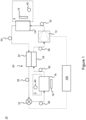
- Figure 7 schematically shows a range of values for the control variable as a horizontal line, with various settings for the control variable indicated along the range.
- the performance setting corresponding to the performance threshold e.g. a minimum cooling rate
- the dynamic control module applies the limit setting as a lower limit to the operational range, effectively constraining the refrigeration circuit to be operated with the limit setting for the control variable.
- the performance setting corresponding to the performance threshold is higher than the limit setting corresponding to optimum performance, and is therefore within the operating range bounded by the limit setting. The dynamic control module therefore adjusts the value of the control valuable towards the performance setting.
- Figure 8 schematically shows a flow diagram of a method 800 of controlling a refrigeration circuit, to vary a control variable of the refrigeration circuit during operation of the refrigeration circuit. It will be described, by way of example only, with reference to the controller 100 and refrigeration circuit 10 described above with respect to Figures 1-4 .
- the controller monitors prevailing conditions of the refrigeration circuit, for example a space temperature of a temperature-controlled space associated with the refrigeration circuit, and optionally one or more further operating conditions as described above.
- a simulation module of the controller determines a limit setting for a control variable of the refrigeration circuit.
- the simulation module conducts an iterative optimisation procedure to determine the limit setting.
- the iterative optimisation procedure is defined based on an objective function which relates to an operating efficiency of the refrigeration circuit.
- the objective function is determined based on evaluating a model and is determined by evaluating a model for the refrigeration circuit at a respective simulated operating point (i.e. an operating point which varies according to iterative variation of the control variable).
- the simulated operating point is defined by a monitored set of prevailing conditions, and by a simulated setting for the control variable.
- the determined limit setting 805 resulting from the optimisation procedure is stored, for example in a memory of the controller.
- the dynamic control module of the controller monitors a performance parameter, for example relating to a rate of change of the temperature-controlled space, or a monitored cooling capacity of the system.
- the dynamic control module adjusts an operating setting of the control variable (i.e. a setting that is applied to the refrigeration circuit, rather than merely simulated) within an operating range, to target a performance threshold 807 (e.g. a predetermined performance threshold stored in a memory of the controller) for the monitored performance parameter.
- the limit setting received from the simulation module is applied as a limit to the operating range, for example as described above.
- Figure 9 schematically shows a machine-readable medium 900 comprising instructions 902.
- the instructions are defined so that, when executed by a compressor 904, they cause performance of a method as described herein, for example as described with reference to Figure 8 , and/or with reference to any of Figures 1-7 .
Landscapes
- Engineering & Computer Science (AREA)
- Physics & Mathematics (AREA)
- Mechanical Engineering (AREA)
- Thermal Sciences (AREA)
- General Engineering & Computer Science (AREA)
- Devices That Are Associated With Refrigeration Equipment (AREA)
- Air Conditioning Control Device (AREA)
- Feedback Control In General (AREA)
Abstract
Description
- The invention relates to control of a refrigeration circuit, for example as may be used in an HVAC-R system. In particular, the invention relates to controlling a control variable of the refrigeration circuit based on a minimum performance parameter and optimisation relating to efficiency.
- It is known to provide refrigeration circuits which can be operated through an operating map of operating conditions. It is known to adjust various operating parameters during operation of a refrigeration circuit, such as a compressor speed or an expansion valve setting. Such control is typically based on targeting thermodynamic parameters around the refrigeration circuit or in a process medium, such as a target superheat upstream of the compressor, or a target temperature of a process medium which exchanges heat with a refrigerant of the refrigeration circuit at a heat exchanger of the refrigeration circuit.
- It is desirable to provide an improved method of controlling a refrigeration circuit based on performance requirements of the system.
- According to a first aspect there is disclosed a controller for a refrigeration circuit ; wherein the controller is configured to monitor a set of prevailing conditions relating to the refrigeration circuit including a space temperature of a temperature-controlled space associated with the refrigeration circuit;
- wherein the controller has a simulation module configured to determine a limit setting of a control variable for the refrigeration circuit by an iterative optimisation procedure based on a model corresponding to the refrigeration circuit;
- wherein the iterative optimisation procedure is defined based on an objective function which relates to an operating efficiency of the refrigeration circuit and is determined based on evaluating the model for a respective simulated operating point; wherein the simulated operating point is defined by the monitored set of prevailing conditions, and by a simulated setting for the control variable which is iteratively varied in the optimisation procedure, and
- wherein the controller further comprises a dynamic control module configured to: adjust an operating setting of the control variable within an operating range to target a performance threshold for a monitored performance parameter, based on monitoring of the performance parameter during operation of the refrigeration circuit; and apply the limit setting received from the simulation module as a limit to the operating range.
- The limit setting for the control variable is defined based on a simulated operating point determined to correspond to the objective function being at an optimal value (e.g. a maximum) or within a range including the optimal value (e.g. a maximum) corresponding to near-optimal performance.
- It may be that the dynamic control module is configured to adjust the operating setting of the control variable during operation of the refrigeration circuit, based on concurrent monitoring of the performance parameter during operation of the refrigeration circuit.
- It may be that the model does not determine the performance parameter.
- It may be that the objective function is a coefficient of performance.
- It may be that the coefficient of performance is determined based on a simulated heat transfer capacity (e.g. cooling capacity) and a corresponding simulated power consumption, each determined based on the model.
- The heat transfer capacity may correspond to a cooling capacity when the prevailing conditions relate to operation of the refrigeration circuit in a cooling mode in which the second heat exchanger is operated as an evaporator for cooling an associated temperature-controlled environment. The heat transfer capacity may correspond to a heating capacity when the prevailing conditions relate to operation of the refrigeration circuit in a cooling mode in which the second heat exchanger is operated as a condenser for heating the associated temperature-controlled environment.
- The controller may be configured to simulate operation of the refrigeration circuit at the simulated operating point using the digital twin.
- It may be that the monitored performance parameter is a rate of change of a monitored condition relating to the refrigeration circuit.
- It may be that the targeted performance threshold for the monitored performance parameter is selected from the group consisting of: (i) a heat transfer parameter relating to a heat transfer capacity of the refrigeration circuit, for example: a predetermined minimum heat transfer capacity of the refrigeration circuit; or a predetermined minimum magnitude of a monitored rate of change of a space temperature of the temperature-controlled space; and (ii) a predetermined minimum refrigerant superheat at a superheat monitoring location along a suction line of the refrigeration circuit.
- It may be that the dynamic control module comprises a PI or PID control module configured to control the control variable of the refrigeration circuit during operation of the refrigeration circuit. It may be that the PI or PID control module is configured to vary the control variable based on an error signal relating to a difference between the performance threshold and the monitored performance parameter. It may be that the limit setting for the control variable is applied as saturation limit of the PI or PID controller.
- It may be that the targeted performance threshold for the monitored performance parameter is a predetermined minimum magnitude of a monitored rate of change of the space temperature. It may be that the PI or PID control module (i) is configured to control an operating parameter of the compressor as the control variable; and (ii) is configured to determine the error signal as the difference between the predetermined minimum magnitude of the rate of change of the space temperature and a monitored rate of change of the space temperature.
- It may be that the model is configured to determine the simulated power consumption based on one or more of: (i) an operating parameter of the compressor, as the control variable or derived from the set of prevailing conditions; (ii) an operating parameter of a first fan associated with the first heat exchanger, as the control variable or derived from the set of prevailing conditions; and/or (iii) an operating parameter of a second fan associated with the second heat exchanger, as the control variable or derived from the set of prevailing conditions.
- The controller may be configured to repeatedly conduct the optimisation procedure and update the limit setting. The controller may be configured to repeat the optimisation procedure at predetermined intervals; and/or repeat the optimisation procedure based on determining a threshold change or rate of change of a prevailing condition of the set of prevailing conditions.
- It may be that the simulation module is configured to determine a limit setting of a plurality of control variables for the refrigeration circuit by the iterative optimisation procedure. It may be that the simulated operating point is defined by the monitored set of prevailing conditions and by respective simulation settings for the plurality of control variables. It may be that, for each control variable, the simulation control module is configured to determine a respective limit setting by the optimisation procedure. It may be that the dynamic control module is configured to adjust each respective operating setting of the control variables within respective operating ranges to target the performance threshold for the monitored performance parameter, and to apply each respective limit setting received from the simulation module as a limit to the respective operating ranges.
- When there are a plurality of control variables, the references above with respect to variation, determination and setting of a control variable or respective limit are to be interpreted as corresponding to the (respective) variation, determination and setting of each respective control variable or limit.
- According to a second aspect there is disclosed a refrigeration circuit comprising a compressor, a first heat exchanger, an expansion device, a second heat exchanger and a controller in accordance with the first aspect.
- According to a third aspect there is disclosed a method of controlling a refrigeration circuit (e.g. in accordance with the second aspect) using a controller according to the first aspect, wherein a control variable of the refrigeration circuit is variable during operation of the refrigeration circuit, the method comprising: monitoring a set of prevailing conditions relating to the refrigeration circuit, including a space temperature of a temperature-controlled space associated with the refrigeration circuit;
- the simulation module conducting the iterative optimisation procedure to determine a limit setting of a control variable for the refrigeration circuit; applying the limit setting as a limit to an operating range for the control variable; monitoring a performance parameter for the refrigeration circuit during operation of the refrigeration circuit; the dynamic control module adjusting an operating setting of the control variable within the operating range to target a performance threshold for the monitored performance parameter;
- whereby the dynamic control module biases operation of the refrigeration circuit to the limit setting of the control variable determined by the optimisation procedure when the limit setting corresponds to compliance with the performance threshold during operation of the refrigeration circuit; and
- whereby the dynamic control module biases operation of the refrigeration circuit to depart from the limit setting of the control variable to achieve the target performance threshold, when the limit setting corresponds to non-compliance with the performance threshold during operation of the refrigeration circuit.
- According to a fourth aspect there is provided a non-transitory machine-readable medium comprising instructions that, when executed by a processor, cause performance of a method in accordance with the third aspect.
- The controller(s) described herein may comprise a processor. The controller and/or the processor may comprise any suitable circuity to cause performance of the methods described herein and as illustrated in the Figures. The controller or processor may comprise: at least one application specific integrated circuit (ASIC); and/or at least one field programmable gate array (FPGA); and/or single or multi-processor architectures; and/or sequential (Von Neumann)/parallel architectures; and/or at least one programmable logic controllers (PLCs); and/or at least one microprocessor; and/or at least one microcontroller; and/or a central processing unit (CPU), to perform the methods and or stated functions for which the controller or processor is configured.
- The controller may comprise or the processor may comprise or be in communication with one or more memories that store that data described herein, and/or that store machine readable instructions (e.g. software) for performing the processes and functions described herein (e.g. determinations of parameters and execution of control routines).
- The memory may be any suitable non-transitory computer readable storage medium, data storage device or devices, and may comprise a hard disk and/or solid state memory (such as flash memory). In some examples, the computer readable instructions may be transferred to the memory via a wireless signal or via a wired signal. The memory may be permanent non-removable memory, or may be removable memory (such as a universal serial bus (USB) flash drive). The memory may store a computer program comprising computer readable instructions that, when read by a processor or controller, causes performance of the methods described herein, and/or as illustrated in the Figures. The computer program may be software or firmware, or be a combination of software and firmware.
- The skilled person will appreciate that except where mutually exclusive, a feature described in relation to any one of the above aspects may be applied mutatis mutandis to any other aspect. Furthermore, except where mutually exclusive any feature described herein may be applied to any aspect and/or combined with any other features described herein.
- The invention will be described with reference to the drawings, in which:
-
Figure 1 schematically shows a refrigeration circuit; -
Figure 2 schematically shows a flow diagram of control actions conducted by a simulation module of a controller for the refrigeration circuit; -
Figure 3 schematically shows the simulation module and dynamic module of the controller; -
Figure 4 schematically shows a flow diagram of control actions conducted by a dynamic module of a controller for the refrigeration circuit; -
Figures 5 and6 show plots of performance and efficiency parameters of a refrigeration circuit through an operating range of a control variable for a refrigeration circuit; -
Figure 7 schematically illustrates example operating ranges of a control variable for a refrigeration circuit; -
Figure 8 is a flow diagram of a method of controlling a refrigeration circuit; and -
Figure 9 schematically shows a machine-readable medium and processor. -
Figure 1 schematically shows an example refrigeration circuit 10 (e.g. heat pump or vapor compression cycle) for transferring heat from one heat exchange medium to another, for example between a controlled environment 2 (e.g. temperature-controlled space) and an ambient environment. Examples applications of such refrigeration circuits include a chiller system (e.g. for centrally heating and cooling a process fluid such as water that circulates within a building or other installation to heat transfer terminals, e.g. for room heating), or a refrigeration system such as an HVAC system or a transport refrigeration system. - The
refrigeration circuit 10 ofFigures 1 comprises acompressor 12, afirst heat exchanger 14, anexpansion device 16, and asecond heat exchanger 18. The first andsecond heat exchangers respective fans - The
refrigeration circuit 10 may be configured to define two flow paths through the heat pump for operation in different modes, namely a cooling mode and a heating mode (conventionally known as a reversible heat pump). - The expressions "heating" and "cooling" refer to the direction of heat transfer with respect to a heat exchange medium which is being actively heated or cooled, for example to maintain a set-point temperature in a temperature-controlled space (e.g. air in a cargo space, or process fluid/water in a chiller system). In the present disclosure, this is referred to as the regulated heat exchange medium.
-
Figure 1 shows the refrigeration circuit in a cooling mode, whereby there is a flow path (indicated by arrows) extending through, in flow order, thecompressor 12, thefirst heat exchanger 14 which functions as a condenser for discharging heat to an ambient heat exchange medium (e.g. ambient air), theexpansion device 16, thesecond heat exchanger 18 which functions as an evaporator for receiving heat from a regulated heat exchange medium in the temperature-controlledspace 2, returning to thecompressor 12. The flow path ofFigure 1 is for cooling the regulated heat exchange medium, and it is thesecond heat exchanger 18 which is in thermal communication with the regulated heat exchange medium. Correspondingly, thefan 15 associated with thefirst heat exchanger 14 may be referred to as acondenser fan 15, and thefan 19 associated with thesecond heat exchanger 18 may be referred to as anevaporator fan 19. - A suitable valve arrangement may be provided to reverse a flow direction for a heating mode as is known in the art, such that the
second heat exchanger 18 functions as a condenser for rejecting heat to the regulated heat exchange medium, and thefirst heat exchanger 14 functions as an evaporator for receiving heat from an ambient heat exchange medium. - The further description is by reference to the refrigeration circuit in the cooling mode shown in
Figure 1 . A portion of the flow path between thecompressor 12 and thecondenser 14 is referred to as the discharge line, a portion of the flow path between thecondenser 14 and theexpansion device 16 is referred to as the liquid line, a portion of the flow path between theexpansion device 16 and theevaporator 18 is referred to as the distribution line, and a portion of the flow path between the evaporator 18 and thecompressor 12 is referred to as the suction line. - A suction
line heat exchanger 20 is provided for heat exchange between refrigerant in the liquid line and the suction line. The suctionline heat exchanger 20 has aliquid line portion 22 along the liquid line, and asuction line portion 24 along the suction line. In other examples, there may be no such suction line heat exchanger. - In use in the cooling mode of
Figure 1 , gaseous refrigerant is compressed at thecompressor 12 to a high pressure and is condensed in thecondenser 14 to reject heat to the ambient heat exchange medium, thereby providing high pressure and high temperature condensed refrigerant in the liquid line. The condensed refrigerant is expanded at theexpansion device 16, to provide a multi-phase refrigerant flow to theevaporator 18. This flow is evaporated in theevaporator 18, before being provided to thecompressor 12. Evaporation at theevaporator 18 cools the regulated heat exchange medium associated with the evaporator. - When present, the suction
line heat exchanger 20 transfers heat from the high temperature liquid refrigerant in the liquid line to the relatively lower temperature refrigerant in the suction line. This may be considered to temporarily remove thermal energy from the refrigerant for a portion of the circuit comprising the expansion device and the evaporator. This may permit the refrigerant to be expanded to a relatively lower pressure and saturation temperature for absorbing heat from the ambient heat exchange medium at the evaporator. The thermal energy returns to the refrigerant at thesuction line portion 24 of the suction line heat exchanger, which may correspond to further evaporation and/or superheating of the refrigerant upstream of thecompressor 12. -
Figure 1 shows further monitoring and control equipment of or associated with therefrigeration circuit 10. Acontroller 100 is provided and is operatively connected to control operating variables of thecompressor 12 and/or theexpansion device 16. Thecontroller 100 may control only one of thecompressor 12 and theexpansion device 16, or may control both. For example, theexpansion valve 16 may be provided with its own controller (e.g. as an electronic expansion valve, EXV), or may be configured as a thermostatic control valve. - The
controller 100 is further coupled to one or more sensors around the refrigeration circuit for monitoring one or more prevailing conditions of the refrigeration circuit, which may include one or more thermodynamic parameters of the refrigerant and/or one or more parameters associated with the ambient heat exchange medium and/or the regulated heat exchange medium. -
Figure 1 shows monitoring locations for such sensors, including a dischargeline monitoring location 32 along the discharge line, a first liquidline monitoring location 34 along the liquid line upstream of the suctionline heat exchanger 20, a second liquidline monitoring location 35 along the liquid line downstream of the suctionline heat exchanger 20, a distributionline monitoring location 36 along the distribution line, a first suctionline monitoring location 38 along the suction line upstream of the suctionline heat exchanger 20 and a second suctionline monitoring location 39 along the suction line downstream of the suctionline heat exchanger 20. Afurther monitoring location 40 is associated with the regulated heat exchange medium, for example a temperature sensor may be provided to monitor a flow of supply air or return air provided to/from the temperature-controlled space2, or a temperature sensor disposed in the temperature-controlledspace 2. Similarly, afurther monitoring location 42 is associated with the ambientheat exchange medium 4, for example a temperature sensor may be provided to monitor a temperature of ambient flow conveyed to the condenser 14 (for example by the condenser fan 15). The temperature sensor may be co-located with thecondenser 14 orcondenser fan 15 for such monitoring, or otherwise provided in the ambient heat exchange medium. Any one or more of the monitoring locations may be used in a refrigeration circuit according to the present disclosure. Further, for any monitoring location provided with at least one sensor may be provided with a temperature sensor and/or a pressure sensor. - Although not schematically shown by links between the monitoring locations and the
controller 100, signals from the pressure and/or temperature sensors may be provided to thecontroller 100 for use in controlling the refrigeration circuit as will be discussed below. -
Figure 2 schematically shows a flow diagram of a control actions implemented by asimulation module 102 of thecontroller 100. Thesimulation module 102 comprises or is configured to reference (e.g. remotely access) amodel 110. - The model is configured to relate one or more parameters that relate to an operating point of the refrigeration circuit to one or more performance parameters of the refrigeration circuit. The expression "operating point" refers to a state of the refrigeration circuit, such that example parameters relating to the operating point describe thermodynamic or operational parameters associated with respective parts of the refrigeration circuit. For example, such parameters may include one or more of: a temperature of the temperature-controlled space 2 (e.g. as monitored by a temperature sensor at monitoring location 40), a temperature of the ambient heat exchange medium (e.g. as monitored by a temperature sensor at monitoring location 42), an operating parameter of the condenser fan 15 (e.g. a fan speed or a power parameter relating to power provided to the fan (e.g. a power, frequency, voltage or current), an operating parameter of the evaporator fan 19 (which may be similar to the operating parameter of the condenser fan), an operating parameter of the expansion device 16 (for example a valve setting relating to a state of the valve, such as a parameter relating to how open the valve is and/or whether it is in a closed state), an operating parameter of the compressor 12 (for example a compressor speed parameter (e.g. an rotary speed (e.g. revolutions per minute), angular speed, or frequency of rotation), or a power parameter relating to power provided to the compressor (e.g. a power, frequency, voltage or current). Further, such parameters may include one or more temperatures or pressures of the refrigerant around the refrigeration circuit. As is known in the art, refrigerant pressure may be used to determine a saturation temperature of the refrigerant, and thereby permit an amount of subcooling or superheating of refrigerant at an associated location to be determined.
- In the example of
Figure 2 , themodel 110 is configured to relate fourparameters performance parameters model 110 is configured to relate these parameters to a cooling capacity of the refrigeration circuit, and a power consumption of the refrigeration circuit. The expression cooling capacity has a well understood meaning in the art, and relates to the amount of heat than can be removed by the system. The SI unit is watt (W), and the cooling capacity is typically derived as the product of a mass flow rate (e.g. of either the ambient heat exchange medium or the regulated heat exchange medium), the respective specific heat capacity (Cp), and the observed temperature change. - Although a particular example of a relation between operating point parameters and performance parameters has been described, it should be appreciated that in other examples the
model 110 may be configured to implement a wide variety of similar relations that relate a different or overlapping set of operating point parameters to a different or overlapping set of performance parameters. Such a relation may be based on any suitable number of operating point parameters (rather than four parameters as in the example above). - As shown in
Figure 2 , three of the exampleoperating point parameters 50 are received as inputs from outside of the simulation module 102 (e.g. from sensors at respective monitoring locations), whereas at least one of theoperating point parameters 150 is iteratively derived by thesimulation module 102, and corresponds to a control variable of the refrigeration circuit. In this example, the respective control variable 150 is thecompressor speed parameter 150. As shown inFigure 2 , this may be derived from outside of the simulation module (102) (e.g. as an output of a motor or motor controller for the compressor) or iteratively derived within thesimulation module 102. It may be that an initial value for thecontrol variable 150 is obtained by observation, and subsequent values for the control variable 150 are determined by thesimulation module 102 without corresponding variation of the control variable 150 as applied to the refrigeration circuit, as will be described in further detail below. - In this example, a
further performance parameter 120 is derived based on theperformance parameters refrigeration circuit 112 and the power consumption of therefrigeration circuit 114. In other examples, themodel 110 may relate theoperating point parameters - At
block 130, thesimulation module 102 is configured to iteratively evaluate the performance parameter (e.g. COP) to determine a value for the control variable which corresponds to an optimum (e.g. maximum) value of the performance parameter (e.g. COP). It is to be appreciated that this evaluation occurs iteratively rather than being based on a single value of the control variable and a single variable of the respective performance parameter.Block 130 of thesimulation module 102 may therefore be considered to implement an iterative adjustment of the control variable to conduct a search for the optimum value of the performance parameter. It is considered that many suitable methods for conducting such an iterative optimisation or search may be implemented, as are known in the art.Block 130 and thesimulation module 102 may therefore be considered to conduct an optimization procedure in which the objective function is defined based on the performance parameter (e.g. to maximise a COP), and the independent variable is thecontrol variable 150. -
Figure 2 shows how the control variable is iteratively adjusted (140) and the adjusted value is provided to themodel 110 for further iterations. The iterative adjustment of the control variable within thesimulation module 102 occurs solely within thesimulation module 102, without corresponding direct adjustment of the value of the control variable applied to the refrigeration circuit during the iterative adjustment. Accordingly, themodel 110 may be considered to operate based on a combination of prevailing operatingconditions 50 derived from monitoring of the refrigeration circuit, and asimulated setting 150 for the control variable. - When block 130 determines that the optimum performance parameter is reached, the corresponding
value 152 for the control variable is output as a limit setting 152 for the control variable. The limit setting is provided to a dynamic control module as will now be described. - As schematically shown in
Figure 3 , thecontroller 100 comprises thesimulation module 102 and adynamic control module 160. Thesimulation module 102 is configured to derive the limit setting for the control variable based on prevailing conditions relating to an operating point of the refrigeration circuit (i.e. without direct adjustment of the control variable as applied in the refrigeration circuit - e.g. without directly adjusting the compressor speed). In contrast, thedynamic control module 160 is configured to adjust operation of the refrigeration circuit by adjusting the control variable as applied in the refrigeration circuit (e.g. directly adjusting the compressor speed). However, thedynamic control module 160 does not simply take thevalue 152 for the control variable determined by thesimulation module 102, but instead determines whether to adopt thevalue 152 based on one or more other performance-related objectives. -
Figure 4 is a flow diagram showing control actions of thedynamic control module 160. As indicated by the dashed arrows inFigure 4 , various parameters are provided from outside of thedynamic control module 160, whereas others may be determined or stored locally to the dynamic control module. Firstly, thedynamic control module 160 receives the limit setting 152 from thesimulation module 102. Secondly, thedynamic control module 160 receives a performance parameter relating to performance of the refrigeration circuit. The performance parameter may be an observed performance parameter, for example derived from monitoring signals from one or more sensors. In the present example, the performance parameter is a rate of change of temperature in the temperature-cooledspace 2, as derived from a series of temperature observations derived by thecontroller 100 from a temperature sensor at therespective monitoring location 42. - The
dynamic control module 160 stores or references aperformance threshold 130 for the respective performance parameter. For example, the performance threshold may correspond to a minimum magnitude of the rate of change of the temperature in the temperature-controlledspace 2 during a cooling operation, for example a minimum magnitude of 0.21 °C/minute. - The
dynamic control module 160 is configured to determine avalue 154 for the control variable based on comparing the performance parameter with the performance threshold; and/or based on the limit setting 152 received from thesimulation module 102, so as to (i) target compliance with the performance threshold, and (ii) apply the limit setting 152 from thesimulation module 102 if this corresponds to compliance with the performance threshold. - The
dynamic control module 160 may determine thevalue 154 for the control variable in any suitable way to achieve this effect. For example, thedynamic control module 160 may be configured to effect gradual changes in the control variable based on the performance parameter comparison and/or the limit setting. - Although a particular example of a performance threshold and associated performance parameter has been described, it should be appreciated that other performance parameters and thresholds may be applied, and it may be that two or more such performance parameters and thresholds are monitored and targeted. For example, in addition or as an alternative to a minimum heat transfer capacity of the refrigeration circuit and/or a minimum magnitude of a rate of change of a space temperature of the temperature-controlled space, the dynamic control module may monitor a performance parameter related to a thermodynamic property associated with the refrigeration circuit, for example a superheat at a superheat monitoring location along a suction line of the refrigeration circuit (e.g. upstream of the compressor, optionally upstream or downstream of any suction line heat exchanger when provided). It may be desirable to monitor such parameters when associated with operating requirements or advantages of the refrigeration circuit. For example, it may be desirable for there to be a minimum superheat in refrigerant provided to the compressor, to prevent slugging and associated adverse effects.
- A preferred implementation of the
dynamic control module 160 is as a PID (proportional-integral-derivative) or PI (proportional-integral) controller. Such a controller is configured to adjust a variable based on a target, for example to reduce an error between two signals while minimising overshoot and related behaviours. A PI (or PID) controller may be used for thedynamic control module 160 to adjust the control variable (e.g. the compressor speed parameter) to minimise an error signal determined as a difference between the performance parameter (e.g. an observed rate of change of temperature in the temperature-controlled space) and the performance threshold for the performance parameter (e.g. a minimum rate of change of that temperature). - When the dynamic control module is implemented as a PI or PID controller, the limit setting for the control variable is applied as a saturation limit of the PI or PID controller, in particular a lower saturation limit (a minimum). A saturation limit of a PI or PID controller is a term of the relevant technical field, relating to a limit value (e.g. maximum or minimum) that the PI or PID can output.
- By applying the limit setting as the lower saturation limit, the PI or PID controller is configured to ensure that the control variable is set to a value which is equal to or greater than the value for optimal operation as determined by the
simulation module 102, but is free to be adjusted to a higher setting that may be required to achieve the minimum performance threshold (e.g. the minimum rate of change of temperature). This provides a particularly efficient implementation of the desired control functionality which minimises control complexity and equipment cost. -
Figures 5 and6 show plots of performance parameters for a refrigeration circuit. In each plot, the X-axis corresponds to variation of the control variable, which in this example is the compressor speed parameter. The plotted quantities are in different units, with thesolid lines dot lines Solid line 502 corresponds to compressor COP, whereassolid line 506 corresponds to total COP. Dash-dot line 504 corresponds to the cooling capacity of the system, whereas dash-dot line 530 corresponds to the performance threshold for a corresponding performance parameter (e.g. a minimum cooling capacity). -
Point 508 on thetotal COP line 506 corresponds to a maximum efficiency for the refrigeration circuit. -
Figure 5 shows two points on the cooling capacity line 504: afirst point 510 corresponding to intersection with the performance threshold line 503; and asecond point 512 corresponding to themaximum efficiency point 508. - The
controller 100 as described above is configured to determine the limit setting 152 for the control variable using thesimulation module 102, such that the limit setting 152 of the control variable corresponds to themaximum efficiency point 508 and thesecond point 512 on thecooling capacity line 504. - The dynamic control module is configured such that, in the absence of the limit setting, it adjusts the value of the control variable to target the performance threshold (e.g. a minimum cooling capacity as represented by line 530). This is represented on
Figure 5 as thefirst point 510 on thecooling capacity line 504, and is annotated where it intersects the X-axis for the control variable as the "performance threshold". - In the example shown in
Figure 5 , the value of the control variable corresponding to the performance threshold is lower than the value of the limit setting for the control variable (corresponding to optimum operation). When the control variable is a compressor speed parameter, this effectively means that it is more efficient to operate at a compressor speed higher than is required to merely meet the performance threshold (e.g. a minimum rate of change of temperature). Thedynamic control module 160 is configured to apply the limit setting as a limit to the operating range of the control variable (in particular a lower limit), and as such thedynamic control module 160 causes the limit setting for the control variable to be applied. The dynamic control module maintains the control variable at the limit setting despite being biased to target the performance threshold, since this bias would only drive the control variable to a lower value and is therefore prevented by the limit setting (e.g. as applied by a lower saturation limit in a PI or PID controller). - In a contrasting example shown in
Figure 6 , the same COP and cooling capacity lines are shown, but the performance threshold is higher such that thefirst point 610 where thecooling capacity line 504 intersects theperformance threshold 630 corresponds to a value for the control variable which is higher than the limit setting (corresponding to optimum performance). The dynamic control module still applies the limit setting as a limit to the operating range of the control variable (in particular a lower limit), but is free to adjust to higher values of the control variable in order to target the performance threshold. For example, the dynamic control module may be adjusted in a range above the limit setting until a value is found which causes performance at the performance threshold (e.g. at a minimum threshold cooling capacity). - These contrasting examples are schematically illustrated in
Figure 7 , which schematically shows a range of values for the control variable as a horizontal line, with various settings for the control variable indicated along the range. In example (A), the performance setting corresponding to the performance threshold (e.g. a minimum cooling rate) is lower than the limit setting corresponding to optimum performance. The dynamic control module applies the limit setting as a lower limit to the operational range, effectively constraining the refrigeration circuit to be operated with the limit setting for the control variable. In example (B) the performance setting corresponding to the performance threshold is higher than the limit setting corresponding to optimum performance, and is therefore within the operating range bounded by the limit setting. The dynamic control module therefore adjusts the value of the control valuable towards the performance setting. -
Figure 8 schematically shows a flow diagram of amethod 800 of controlling a refrigeration circuit, to vary a control variable of the refrigeration circuit during operation of the refrigeration circuit. It will be described, by way of example only, with reference to thecontroller 100 andrefrigeration circuit 10 described above with respect toFigures 1-4 . - In
block 802, the controller monitors prevailing conditions of the refrigeration circuit, for example a space temperature of a temperature-controlled space associated with the refrigeration circuit, and optionally one or more further operating conditions as described above. - In
block 804, a simulation module of the controller determines a limit setting for a control variable of the refrigeration circuit. The simulation module conducts an iterative optimisation procedure to determine the limit setting. The iterative optimisation procedure is defined based on an objective function which relates to an operating efficiency of the refrigeration circuit. The objective function is determined based on evaluating a model and is determined by evaluating a model for the refrigeration circuit at a respective simulated operating point (i.e. an operating point which varies according to iterative variation of the control variable). The simulated operating point is defined by a monitored set of prevailing conditions, and by a simulated setting for the control variable. - As shown in
Figure 8 , the determined limit setting 805 resulting from the optimisation procedure is stored, for example in a memory of the controller. - In
block 806, the dynamic control module of the controller monitors a performance parameter, for example relating to a rate of change of the temperature-controlled space, or a monitored cooling capacity of the system. Inblock 808, the dynamic control module adjusts an operating setting of the control variable (i.e. a setting that is applied to the refrigeration circuit, rather than merely simulated) within an operating range, to target a performance threshold 807 (e.g. a predetermined performance threshold stored in a memory of the controller) for the monitored performance parameter. The limit setting received from the simulation module is applied as a limit to the operating range, for example as described above. -
Figure 9 schematically shows a machine-readable medium 900 comprisinginstructions 902. The instructions are defined so that, when executed by acompressor 904, they cause performance of a method as described herein, for example as described with reference toFigure 8 , and/or with reference to any ofFigures 1-7 .
Claims (15)
- A controller (100) for a refrigeration circuit (10);wherein the controller (100) is configured to monitor a set of prevailing conditions (50) relating to the refrigeration circuit including a space temperature of a temperature-controlled space associated with the refrigeration circuit;wherein the controller has a simulation module (102) configured to determine a limit setting (152) of a control variable for the refrigeration circuit by an iterative optimisation procedure based on a model (110) corresponding to the refrigeration circuit;wherein the iterative optimisation procedure is defined based on an objective function which relates to an operating efficiency (120) of the refrigeration circuit and is determined based on evaluating the model for a respective simulated operating point;wherein the simulated operating point is defined by the monitored set of prevailing conditions (50), and by a simulated setting (150) for the control variable which is iteratively varied in the optimisation procedure, andwherein the controller further comprises a dynamic control module (160) configured to:adjust an operating setting of the control variable within an operating range to target a performance threshold for a monitored performance parameter, based on monitoring of the performance parameter during operation of the refrigeration circuit;apply the limit setting received from the simulation module as a limit to the operating range.
- A controller according to claim 1, wherein the dynamic control module is configured to adjust the operating setting of the control variable during operation of the refrigeration circuit, based on concurrent monitoring of the performance parameter during operation of the refrigeration circuit.
- A controller according to claim 1 or 2, wherein the model does not determine the performance parameter.
- A controller according to any preceding claim, wherein the objective function is a coefficient of performance.
- A controller according to claim 4, wherein the coefficient of performance is determined based on a simulated heat transfer capacity and a corresponding simulated power consumption, each determined based on the model.
- A controller according to any preceding claim, wherein the monitored performance parameter is a rate of change of a monitored condition relating to the refrigeration circuit.
- A controller according to any preceding claim, wherein the targeted performance threshold for the monitored performance parameter is selected from the group consisting of:a heat transfer parameter relating to a heat transfer capacity of the refrigeration circuit, for example:a predetermined minimum heat transfer capacity of the refrigeration circuit; ora predetermined minimum magnitude of a monitored rate of change of a space temperature of the temperature-controlled space;a predetermined minimum refrigerant superheat at a superheat monitoring location along a suction line of the refrigeration circuit.
- A controller according to any preceding claim, wherein the dynamic control module comprises a PI or PID control module configured to control the control variable of the refrigeration circuit during operation of the refrigeration circuit;wherein the PI or PID control module is configured to vary the control variable based on an error signal relating to a difference between the performance threshold and the monitored performance parameter; andwherein the limit setting for the control variable is applied as saturation limit of the PI or PID controller.
- A controller according to claim 8, wherein the targeted performance threshold for the monitored performance parameter is a predetermined minimum magnitude of a monitored rate of change of the space temperature; and
wherein the PI or PID control module:is configured to control an operating parameter of the compressor as the control variable;is configured to determine the error signal as the difference between the predetermined minimum magnitude of the rate of change of the space temperature and a monitored rate of change of the space temperature. - A controller according to claim 6 and optionally any of claims 7-9, wherein the model is configured to determine the simulated power consumption based on one or more of:an operating parameter of the compressor, as the control variable or derived from the set of prevailing conditions;an operating parameter of a first fan associated with the first heat exchanger, as the control variable or derived from the set of prevailing conditions; and/oran operating parameter of a second fan associated with the second heat exchanger, as the control variable or derived from the set of prevailing conditions.
- A controller according to any preceding claim, configured to repeatedly conduct the optimisation procedure and update the limit setting; optionally wherein the controller is configured to:repeat the optimisation procedure at predetermined intervals; and/orrepeat the optimisation procedure based on determining a threshold change or rate of change of a prevailing condition of the set of prevailing conditions.
- A controller according to any preceding claim, wherein the simulation module is configured to determine a limit setting of a plurality of control variables for the refrigeration circuit by the iterative optimisation procedure;wherein the simulated operating point is defined by the monitored set of prevailing conditions and by respective simulation settings for the plurality of control variables;wherein for each control variable, the simulation control module is configured to determine a respective limit setting by the optimisation procedure;wherein the dynamic control module is configured to adjust each respective operating setting of the control variables within respective operating ranges to target the performance threshold for the monitored performance parameter, and to apply each respective limit setting received from the simulation module as a limit to the respective operating ranges.
- A refrigeration circuit (10) comprising a compressor (12), a first heat exchanger (14), an expansion device (16), a second heat exchanger (18) and a controller (100);
wherein the controller (100) is in accordance with any preceding claim. - A method of controlling a refrigeration circuit using a controller according to any preceding claim, wherein a control variable of the refrigeration circuit is variable during operation of the refrigeration circuit, the method comprising:monitoring a set of prevailing conditions relating to the refrigeration circuit, including a space temperature of a temperature-controlled space associated with the refrigeration circuit;the simulation module conducting the iterative optimisation procedure to determine a limit setting of a control variable for the refrigeration circuit;applying the limit setting as a limit to an operating range for the control variable;monitoring a performance parameter for the refrigeration circuit during operation of the refrigeration circuit;the dynamic control module adjusting an operating setting of the control variable within the operating range to target a performance threshold for the monitored performance parameter;whereby the dynamic control module biases operation of the refrigeration circuit to the limit setting of the control variable determined by the optimisation procedure when the limit setting corresponds to compliance with the performance threshold during operation of the refrigeration circuit; andwhereby the dynamic control module biases operation of the refrigeration circuit to depart from the limit setting of the control variable to achieve the target performance threshold, when the limit setting corresponds to non-compliance with the performance threshold during operation of the refrigeration circuit.
- A non-transitory machine-readable medium comprising instructions that, when executed by a processor, cause performance of a method in accordance with claim 14.
Priority Applications (4)
| Application Number | Priority Date | Filing Date | Title |
|---|---|---|---|
| EP23157934.3A EP4421415B1 (en) | 2023-02-22 | 2023-02-22 | Control of a refrigeration circuit |
| CN202480013898.8A CN120659960A (en) | 2023-02-22 | 2024-02-21 | Control of refrigeration circuit |
| PCT/EP2024/054422 WO2024175658A1 (en) | 2023-02-22 | 2024-02-21 | Control of a refrigeration circuit |
| US18/584,484 US20240280303A1 (en) | 2023-02-22 | 2024-02-22 | Control of a refrigeration circuit |
Applications Claiming Priority (1)
| Application Number | Priority Date | Filing Date | Title |
|---|---|---|---|
| EP23157934.3A EP4421415B1 (en) | 2023-02-22 | 2023-02-22 | Control of a refrigeration circuit |
Publications (2)
| Publication Number | Publication Date |
|---|---|
| EP4421415A1 true EP4421415A1 (en) | 2024-08-28 |
| EP4421415B1 EP4421415B1 (en) | 2025-02-12 |
Family
ID=85328840
Family Applications (1)
| Application Number | Title | Priority Date | Filing Date |
|---|---|---|---|
| EP23157934.3A Active EP4421415B1 (en) | 2023-02-22 | 2023-02-22 | Control of a refrigeration circuit |
Country Status (4)
| Country | Link |
|---|---|
| US (1) | US20240280303A1 (en) |
| EP (1) | EP4421415B1 (en) |
| CN (1) | CN120659960A (en) |
| WO (1) | WO2024175658A1 (en) |
Families Citing this family (1)
| Publication number | Priority date | Publication date | Assignee | Title |
|---|---|---|---|---|
| CN119730201B (en) * | 2025-02-27 | 2025-06-24 | 上海艾克森股份有限公司 | Control method and system for wide-area optimal efficiency of data center cold source system |
Citations (4)
| Publication number | Priority date | Publication date | Assignee | Title |
|---|---|---|---|---|
| US6378315B1 (en) * | 2000-05-03 | 2002-04-30 | Computer Process Controls Inc. | Wireless method and apparatus for monitoring and controlling food temperature |
| JP3475915B2 (en) * | 1993-09-01 | 2003-12-10 | ダイキン工業株式会社 | Air conditioner condition monitoring device |
| EP3317596A1 (en) * | 2015-06-30 | 2018-05-09 | Emerson Climate Technologies Retail Solutions, Inc. | Maintenance and diagnostics for refrigeration systems |
| US20190293308A1 (en) * | 2016-02-18 | 2019-09-26 | Johnson Controls Technology Company | Extremum-seeking control system for a plant |
Family Cites Families (3)
| Publication number | Priority date | Publication date | Assignee | Title |
|---|---|---|---|---|
| KR100466432B1 (en) * | 2002-11-15 | 2005-01-14 | 삼성에스디에스 주식회사 | Method for analysis of efficiency in turbo refrigerator and apparatus thereof |
| US20100107661A1 (en) * | 2007-02-02 | 2010-05-06 | Awwad Nader S | Method for operating transport refrigeration unit with remote evaporator |
| ES2834548T3 (en) * | 2015-06-24 | 2021-06-17 | Emerson Climate Tech Gmbh | Cross-mapping of components in a refrigeration system |
-
2023
- 2023-02-22 EP EP23157934.3A patent/EP4421415B1/en active Active
-
2024
- 2024-02-21 WO PCT/EP2024/054422 patent/WO2024175658A1/en not_active Ceased
- 2024-02-21 CN CN202480013898.8A patent/CN120659960A/en active Pending
- 2024-02-22 US US18/584,484 patent/US20240280303A1/en active Pending
Patent Citations (4)
| Publication number | Priority date | Publication date | Assignee | Title |
|---|---|---|---|---|
| JP3475915B2 (en) * | 1993-09-01 | 2003-12-10 | ダイキン工業株式会社 | Air conditioner condition monitoring device |
| US6378315B1 (en) * | 2000-05-03 | 2002-04-30 | Computer Process Controls Inc. | Wireless method and apparatus for monitoring and controlling food temperature |
| EP3317596A1 (en) * | 2015-06-30 | 2018-05-09 | Emerson Climate Technologies Retail Solutions, Inc. | Maintenance and diagnostics for refrigeration systems |
| US20190293308A1 (en) * | 2016-02-18 | 2019-09-26 | Johnson Controls Technology Company | Extremum-seeking control system for a plant |
Also Published As
| Publication number | Publication date |
|---|---|
| US20240280303A1 (en) | 2024-08-22 |
| EP4421415B1 (en) | 2025-02-12 |
| CN120659960A (en) | 2025-09-16 |
| WO2024175658A1 (en) | 2024-08-29 |
Similar Documents
| Publication | Publication Date | Title |
|---|---|---|
| CN101646911B (en) | Optimization of air cooled chiller system operation | |
| CN109237713A (en) | Water multi-connected unit operation control method and device, medium and water multi-connected air conditioning system | |
| US10941951B2 (en) | Systems and methods for temperature and humidity control | |
| JP6950191B2 (en) | Air conditioner | |
| EP3267127A1 (en) | Control device and method for refrigeration cycle device | |
| US11137164B2 (en) | Control systems and methods for heat pump systems | |
| JP7093031B2 (en) | Information processing equipment, information processing methods, and programs | |
| CN101680699B (en) | Free Cooling Capacity Control of Air Conditioning Systems | |
| Chen et al. | A study on the operational stability of a refrigeration system having a variable speed compressor | |
| JP7284441B1 (en) | Abnormality diagnosis device, method and program | |
| US20240280303A1 (en) | Control of a refrigeration circuit | |
| US20230259111A1 (en) | Abnormality detection system and refrigerator, abnormality detection method, and abnormality detection program | |
| EP3686519B1 (en) | A system having an optimised subcooler and a method of operating the system | |
| EP4170263A1 (en) | Heat pump, methods of operation and simulation | |
| US20220412623A1 (en) | Evaporator apparatus | |
| JP2017053572A (en) | Air conditioner | |
| US20210164683A1 (en) | System and Method for Compressor Optimization and System Cycling | |
| KR20140052340A (en) | Air conditioner and method for controlling the same | |
| CN118414527A (en) | Method for controlling a cyclic process system and a compression assembly | |
| JP7098513B2 (en) | Environment forming device and cooling device | |
| CN114484733A (en) | Expansion valve control method and device and air conditioning system | |
| Shafiei et al. | Modeling supermarket refrigeration systems for supervisory control in smart grid | |
| US12523405B2 (en) | System and method for controlling head pressure in a refrigeration system | |
| CN118265883A (en) | System and method for controlling expansion valve flow and compressor speed of a refrigeration circuit under conditions of rapid changes in heat load | |
| Örfelth | Fuzzy Logic inComparison to PID forHeat Pump Control |
Legal Events
| Date | Code | Title | Description |
|---|---|---|---|
| PUAI | Public reference made under article 153(3) epc to a published international application that has entered the european phase |
Free format text: ORIGINAL CODE: 0009012 |
|
| STAA | Information on the status of an ep patent application or granted ep patent |
Free format text: STATUS: REQUEST FOR EXAMINATION WAS MADE |
|
| REG | Reference to a national code |
Ref country code: DE Ref legal event code: R079 Free format text: PREVIOUS MAIN CLASS: F25B0049000000 Ipc: F25B0049020000 Ref country code: DE Ref legal event code: R079 Ref document number: 602023001952 Country of ref document: DE Free format text: PREVIOUS MAIN CLASS: F25B0049000000 Ipc: F25B0049020000 |
|
| 17P | Request for examination filed |
Effective date: 20240116 |
|
| AK | Designated contracting states |
Kind code of ref document: A1 Designated state(s): AL AT BE BG CH CY CZ DE DK EE ES FI FR GB GR HR HU IE IS IT LI LT LU LV MC ME MK MT NL NO PL PT RO RS SE SI SK SM TR |
|
| GRAP | Despatch of communication of intention to grant a patent |
Free format text: ORIGINAL CODE: EPIDOSNIGR1 |
|
| STAA | Information on the status of an ep patent application or granted ep patent |
Free format text: STATUS: GRANT OF PATENT IS INTENDED |
|
| RIC1 | Information provided on ipc code assigned before grant |
Ipc: F25B 40/00 20060101ALI20240824BHEP Ipc: F25B 49/02 20060101AFI20240824BHEP |
|
| INTG | Intention to grant announced |
Effective date: 20240906 |
|
| GRAS | Grant fee paid |
Free format text: ORIGINAL CODE: EPIDOSNIGR3 |
|
| GRAA | (expected) grant |
Free format text: ORIGINAL CODE: 0009210 |
|
| STAA | Information on the status of an ep patent application or granted ep patent |
Free format text: STATUS: THE PATENT HAS BEEN GRANTED |
|
| AK | Designated contracting states |
Kind code of ref document: B1 Designated state(s): AL AT BE BG CH CY CZ DE DK EE ES FI FR GB GR HR HU IE IS IT LI LT LU LV MC ME MK MT NL NO PL PT RO RS SE SI SK SM TR |
|
| REG | Reference to a national code |
Ref country code: GB Ref legal event code: FG4D |
|
| REG | Reference to a national code |
Ref country code: CH Ref legal event code: EP |
|
| REG | Reference to a national code |
Ref country code: DE Ref legal event code: R096 Ref document number: 602023001952 Country of ref document: DE |
|
| P01 | Opt-out of the competence of the unified patent court (upc) registered |
Free format text: CASE NUMBER: APP_4161/2025 Effective date: 20250127 |
|
| REG | Reference to a national code |
Ref country code: IE Ref legal event code: FG4D |
|
| PGFP | Annual fee paid to national office [announced via postgrant information from national office to epo] |
Ref country code: AT Payment date: 20250417 Year of fee payment: 3 |
|
| REG | Reference to a national code |
Ref country code: NL Ref legal event code: MP Effective date: 20250212 |
|
| PG25 | Lapsed in a contracting state [announced via postgrant information from national office to epo] |
Ref country code: RS Free format text: LAPSE BECAUSE OF FAILURE TO SUBMIT A TRANSLATION OF THE DESCRIPTION OR TO PAY THE FEE WITHIN THE PRESCRIBED TIME-LIMIT Effective date: 20250512 |
|
| PG25 | Lapsed in a contracting state [announced via postgrant information from national office to epo] |
Ref country code: FI Free format text: LAPSE BECAUSE OF FAILURE TO SUBMIT A TRANSLATION OF THE DESCRIPTION OR TO PAY THE FEE WITHIN THE PRESCRIBED TIME-LIMIT Effective date: 20250212 |
|
| PG25 | Lapsed in a contracting state [announced via postgrant information from national office to epo] |
Ref country code: PL Free format text: LAPSE BECAUSE OF FAILURE TO SUBMIT A TRANSLATION OF THE DESCRIPTION OR TO PAY THE FEE WITHIN THE PRESCRIBED TIME-LIMIT Effective date: 20250212 |
|
| PG25 | Lapsed in a contracting state [announced via postgrant information from national office to epo] |
Ref country code: ES Free format text: LAPSE BECAUSE OF FAILURE TO SUBMIT A TRANSLATION OF THE DESCRIPTION OR TO PAY THE FEE WITHIN THE PRESCRIBED TIME-LIMIT Effective date: 20250212 |
|
| REG | Reference to a national code |
Ref country code: LT Ref legal event code: MG9D |
|
| PG25 | Lapsed in a contracting state [announced via postgrant information from national office to epo] |
Ref country code: IS Free format text: LAPSE BECAUSE OF FAILURE TO SUBMIT A TRANSLATION OF THE DESCRIPTION OR TO PAY THE FEE WITHIN THE PRESCRIBED TIME-LIMIT Effective date: 20250612 Ref country code: NO Free format text: LAPSE BECAUSE OF FAILURE TO SUBMIT A TRANSLATION OF THE DESCRIPTION OR TO PAY THE FEE WITHIN THE PRESCRIBED TIME-LIMIT Effective date: 20250512 |
|
| PG25 | Lapsed in a contracting state [announced via postgrant information from national office to epo] |
Ref country code: NL Free format text: LAPSE BECAUSE OF FAILURE TO SUBMIT A TRANSLATION OF THE DESCRIPTION OR TO PAY THE FEE WITHIN THE PRESCRIBED TIME-LIMIT Effective date: 20250212 |
|
| PG25 | Lapsed in a contracting state [announced via postgrant information from national office to epo] |
Ref country code: HR Free format text: LAPSE BECAUSE OF FAILURE TO SUBMIT A TRANSLATION OF THE DESCRIPTION OR TO PAY THE FEE WITHIN THE PRESCRIBED TIME-LIMIT Effective date: 20250212 |
|
| PG25 | Lapsed in a contracting state [announced via postgrant information from national office to epo] |
Ref country code: PT Free format text: LAPSE BECAUSE OF FAILURE TO SUBMIT A TRANSLATION OF THE DESCRIPTION OR TO PAY THE FEE WITHIN THE PRESCRIBED TIME-LIMIT Effective date: 20250612 Ref country code: LV Free format text: LAPSE BECAUSE OF FAILURE TO SUBMIT A TRANSLATION OF THE DESCRIPTION OR TO PAY THE FEE WITHIN THE PRESCRIBED TIME-LIMIT Effective date: 20250212 |
|
| PG25 | Lapsed in a contracting state [announced via postgrant information from national office to epo] |
Ref country code: GR Free format text: LAPSE BECAUSE OF FAILURE TO SUBMIT A TRANSLATION OF THE DESCRIPTION OR TO PAY THE FEE WITHIN THE PRESCRIBED TIME-LIMIT Effective date: 20250513 Ref country code: BG Free format text: LAPSE BECAUSE OF FAILURE TO SUBMIT A TRANSLATION OF THE DESCRIPTION OR TO PAY THE FEE WITHIN THE PRESCRIBED TIME-LIMIT Effective date: 20250212 |
|
| PG25 | Lapsed in a contracting state [announced via postgrant information from national office to epo] |
Ref country code: SE Free format text: LAPSE BECAUSE OF FAILURE TO SUBMIT A TRANSLATION OF THE DESCRIPTION OR TO PAY THE FEE WITHIN THE PRESCRIBED TIME-LIMIT Effective date: 20250212 |
|
| PG25 | Lapsed in a contracting state [announced via postgrant information from national office to epo] |
Ref country code: SM Free format text: LAPSE BECAUSE OF FAILURE TO SUBMIT A TRANSLATION OF THE DESCRIPTION OR TO PAY THE FEE WITHIN THE PRESCRIBED TIME-LIMIT Effective date: 20250212 |
|
| PG25 | Lapsed in a contracting state [announced via postgrant information from national office to epo] |
Ref country code: DK Free format text: LAPSE BECAUSE OF FAILURE TO SUBMIT A TRANSLATION OF THE DESCRIPTION OR TO PAY THE FEE WITHIN THE PRESCRIBED TIME-LIMIT Effective date: 20250212 |
|
| PG25 | Lapsed in a contracting state [announced via postgrant information from national office to epo] |
Ref country code: IT Free format text: LAPSE BECAUSE OF FAILURE TO SUBMIT A TRANSLATION OF THE DESCRIPTION OR TO PAY THE FEE WITHIN THE PRESCRIBED TIME-LIMIT Effective date: 20250212 Ref country code: LU Free format text: LAPSE BECAUSE OF NON-PAYMENT OF DUE FEES Effective date: 20250222 |
|
| PG25 | Lapsed in a contracting state [announced via postgrant information from national office to epo] |
Ref country code: AT Free format text: LAPSE BECAUSE OF FAILURE TO SUBMIT A TRANSLATION OF THE DESCRIPTION OR TO PAY THE FEE WITHIN THE PRESCRIBED TIME-LIMIT Effective date: 20250212 |
|
| PG25 | Lapsed in a contracting state [announced via postgrant information from national office to epo] |
Ref country code: EE Free format text: LAPSE BECAUSE OF FAILURE TO SUBMIT A TRANSLATION OF THE DESCRIPTION OR TO PAY THE FEE WITHIN THE PRESCRIBED TIME-LIMIT Effective date: 20250212 Ref country code: CZ Free format text: LAPSE BECAUSE OF FAILURE TO SUBMIT A TRANSLATION OF THE DESCRIPTION OR TO PAY THE FEE WITHIN THE PRESCRIBED TIME-LIMIT Effective date: 20250212 |
|
| PG25 | Lapsed in a contracting state [announced via postgrant information from national office to epo] |
Ref country code: RO Free format text: LAPSE BECAUSE OF FAILURE TO SUBMIT A TRANSLATION OF THE DESCRIPTION OR TO PAY THE FEE WITHIN THE PRESCRIBED TIME-LIMIT Effective date: 20250212 |
|
| PG25 | Lapsed in a contracting state [announced via postgrant information from national office to epo] |
Ref country code: SK Free format text: LAPSE BECAUSE OF FAILURE TO SUBMIT A TRANSLATION OF THE DESCRIPTION OR TO PAY THE FEE WITHIN THE PRESCRIBED TIME-LIMIT Effective date: 20250212 |
|
| REG | Reference to a national code |
Ref country code: DE Ref legal event code: R097 Ref document number: 602023001952 Country of ref document: DE |
|
| REG | Reference to a national code |
Ref country code: BE Ref legal event code: MM Effective date: 20250228 |
|
| PLBE | No opposition filed within time limit |
Free format text: ORIGINAL CODE: 0009261 |
|
| STAA | Information on the status of an ep patent application or granted ep patent |
Free format text: STATUS: NO OPPOSITION FILED WITHIN TIME LIMIT |
|
| PG25 | Lapsed in a contracting state [announced via postgrant information from national office to epo] |
Ref country code: MC Free format text: LAPSE BECAUSE OF FAILURE TO SUBMIT A TRANSLATION OF THE DESCRIPTION OR TO PAY THE FEE WITHIN THE PRESCRIBED TIME-LIMIT Effective date: 20250212 |
|
| PG25 | Lapsed in a contracting state [announced via postgrant information from national office to epo] |
Ref country code: BE Free format text: LAPSE BECAUSE OF NON-PAYMENT OF DUE FEES Effective date: 20250228 |
|
| PG25 | Lapsed in a contracting state [announced via postgrant information from national office to epo] |
Ref country code: IE Free format text: LAPSE BECAUSE OF NON-PAYMENT OF DUE FEES Effective date: 20250222 |
|
| 26N | No opposition filed |
Effective date: 20251113 |
|
| PGFP | Annual fee paid to national office [announced via postgrant information from national office to epo] |
Ref country code: DE Payment date: 20260121 Year of fee payment: 4 |
|
| PGFP | Annual fee paid to national office [announced via postgrant information from national office to epo] |
Ref country code: FR Payment date: 20260121 Year of fee payment: 4 |