EP4421402A2 - Expandable environmental control unit - Google Patents
Expandable environmental control unit Download PDFInfo
- Publication number
- EP4421402A2 EP4421402A2 EP24187752.1A EP24187752A EP4421402A2 EP 4421402 A2 EP4421402 A2 EP 4421402A2 EP 24187752 A EP24187752 A EP 24187752A EP 4421402 A2 EP4421402 A2 EP 4421402A2
- Authority
- EP
- European Patent Office
- Prior art keywords
- coupled
- carriage
- base section
- movement
- control unit
- Prior art date
- Legal status (The legal status is an assumption and is not a legal conclusion. Google has not performed a legal analysis and makes no representation as to the accuracy of the status listed.)
- Pending
Links
Images


Classifications
-
- F—MECHANICAL ENGINEERING; LIGHTING; HEATING; WEAPONS; BLASTING
- F24—HEATING; RANGES; VENTILATING
- F24F—AIR-CONDITIONING; AIR-HUMIDIFICATION; VENTILATION; USE OF AIR CURRENTS FOR SCREENING
- F24F1/00—Room units for air-conditioning, e.g. separate or self-contained units or units receiving primary air from a central station
- F24F1/0003—Room units for air-conditioning, e.g. separate or self-contained units or units receiving primary air from a central station characterised by a split arrangement, wherein parts of the air-conditioning system, e.g. evaporator and condenser, are in separately located units
-
- F—MECHANICAL ENGINEERING; LIGHTING; HEATING; WEAPONS; BLASTING
- F04—POSITIVE - DISPLACEMENT MACHINES FOR LIQUIDS; PUMPS FOR LIQUIDS OR ELASTIC FLUIDS
- F04D—NON-POSITIVE-DISPLACEMENT PUMPS
- F04D29/00—Details, component parts, or accessories
- F04D29/60—Mounting; Assembling; Disassembling
- F04D29/601—Mounting; Assembling; Disassembling specially adapted for elastic fluid pumps
-
- F—MECHANICAL ENGINEERING; LIGHTING; HEATING; WEAPONS; BLASTING
- F04—POSITIVE - DISPLACEMENT MACHINES FOR LIQUIDS; PUMPS FOR LIQUIDS OR ELASTIC FLUIDS
- F04D—NON-POSITIVE-DISPLACEMENT PUMPS
- F04D29/00—Details, component parts, or accessories
- F04D29/60—Mounting; Assembling; Disassembling
- F04D29/64—Mounting; Assembling; Disassembling of axial pumps
- F04D29/644—Mounting; Assembling; Disassembling of axial pumps especially adapted for elastic fluid pumps
- F04D29/646—Mounting or removal of fans
-
- F—MECHANICAL ENGINEERING; LIGHTING; HEATING; WEAPONS; BLASTING
- F24—HEATING; RANGES; VENTILATING
- F24F—AIR-CONDITIONING; AIR-HUMIDIFICATION; VENTILATION; USE OF AIR CURRENTS FOR SCREENING
- F24F1/00—Room units for air-conditioning, e.g. separate or self-contained units or units receiving primary air from a central station
- F24F1/0007—Indoor units, e.g. fan coil units
- F24F1/0018—Indoor units, e.g. fan coil units characterised by fans
- F24F1/0022—Centrifugal or radial fans
-
- F—MECHANICAL ENGINEERING; LIGHTING; HEATING; WEAPONS; BLASTING
- F24—HEATING; RANGES; VENTILATING
- F24F—AIR-CONDITIONING; AIR-HUMIDIFICATION; VENTILATION; USE OF AIR CURRENTS FOR SCREENING
- F24F1/00—Room units for air-conditioning, e.g. separate or self-contained units or units receiving primary air from a central station
- F24F1/0007—Indoor units, e.g. fan coil units
- F24F1/0043—Indoor units, e.g. fan coil units characterised by mounting arrangements
- F24F1/0057—Indoor units, e.g. fan coil units characterised by mounting arrangements mounted in or on a wall
-
- F—MECHANICAL ENGINEERING; LIGHTING; HEATING; WEAPONS; BLASTING
- F24—HEATING; RANGES; VENTILATING
- F24F—AIR-CONDITIONING; AIR-HUMIDIFICATION; VENTILATION; USE OF AIR CURRENTS FOR SCREENING
- F24F1/00—Room units for air-conditioning, e.g. separate or self-contained units or units receiving primary air from a central station
- F24F1/02—Self-contained room units for air-conditioning, i.e. with all apparatus for treatment installed in a common casing
- F24F1/022—Self-contained room units for air-conditioning, i.e. with all apparatus for treatment installed in a common casing comprising a compressor cycle
-
- F—MECHANICAL ENGINEERING; LIGHTING; HEATING; WEAPONS; BLASTING
- F24—HEATING; RANGES; VENTILATING
- F24F—AIR-CONDITIONING; AIR-HUMIDIFICATION; VENTILATION; USE OF AIR CURRENTS FOR SCREENING
- F24F1/00—Room units for air-conditioning, e.g. separate or self-contained units or units receiving primary air from a central station
- F24F1/02—Self-contained room units for air-conditioning, i.e. with all apparatus for treatment installed in a common casing
- F24F1/04—Arrangements for portability
-
- F—MECHANICAL ENGINEERING; LIGHTING; HEATING; WEAPONS; BLASTING
- F24—HEATING; RANGES; VENTILATING
- F24F—AIR-CONDITIONING; AIR-HUMIDIFICATION; VENTILATION; USE OF AIR CURRENTS FOR SCREENING
- F24F1/00—Room units for air-conditioning, e.g. separate or self-contained units or units receiving primary air from a central station
- F24F1/06—Separate outdoor units, e.g. outdoor unit to be linked to a separate room comprising a compressor and a heat exchanger
- F24F1/20—Electric components for separate outdoor units
- F24F1/24—Cooling of electric components
-
- F—MECHANICAL ENGINEERING; LIGHTING; HEATING; WEAPONS; BLASTING
- F24—HEATING; RANGES; VENTILATING
- F24F—AIR-CONDITIONING; AIR-HUMIDIFICATION; VENTILATION; USE OF AIR CURRENTS FOR SCREENING
- F24F1/00—Room units for air-conditioning, e.g. separate or self-contained units or units receiving primary air from a central station
- F24F1/06—Separate outdoor units, e.g. outdoor unit to be linked to a separate room comprising a compressor and a heat exchanger
- F24F1/36—Drip trays for outdoor units
-
- F—MECHANICAL ENGINEERING; LIGHTING; HEATING; WEAPONS; BLASTING
- F24—HEATING; RANGES; VENTILATING
- F24F—AIR-CONDITIONING; AIR-HUMIDIFICATION; VENTILATION; USE OF AIR CURRENTS FOR SCREENING
- F24F1/00—Room units for air-conditioning, e.g. separate or self-contained units or units receiving primary air from a central station
- F24F1/06—Separate outdoor units, e.g. outdoor unit to be linked to a separate room comprising a compressor and a heat exchanger
- F24F1/38—Fan details of outdoor units, e.g. bell-mouth shaped inlets or fan mountings
-
- F—MECHANICAL ENGINEERING; LIGHTING; HEATING; WEAPONS; BLASTING
- F24—HEATING; RANGES; VENTILATING
- F24F—AIR-CONDITIONING; AIR-HUMIDIFICATION; VENTILATION; USE OF AIR CURRENTS FOR SCREENING
- F24F1/00—Room units for air-conditioning, e.g. separate or self-contained units or units receiving primary air from a central station
- F24F1/06—Separate outdoor units, e.g. outdoor unit to be linked to a separate room comprising a compressor and a heat exchanger
- F24F1/46—Component arrangements in separate outdoor units
- F24F1/48—Component arrangements in separate outdoor units characterised by air airflow, e.g. inlet or outlet airflow
- F24F1/50—Component arrangements in separate outdoor units characterised by air airflow, e.g. inlet or outlet airflow with outlet air in upward direction
-
- F—MECHANICAL ENGINEERING; LIGHTING; HEATING; WEAPONS; BLASTING
- F24—HEATING; RANGES; VENTILATING
- F24F—AIR-CONDITIONING; AIR-HUMIDIFICATION; VENTILATION; USE OF AIR CURRENTS FOR SCREENING
- F24F1/00—Room units for air-conditioning, e.g. separate or self-contained units or units receiving primary air from a central station
- F24F1/06—Separate outdoor units, e.g. outdoor unit to be linked to a separate room comprising a compressor and a heat exchanger
- F24F1/56—Casing or covers of separate outdoor units, e.g. fan guards
-
- F—MECHANICAL ENGINEERING; LIGHTING; HEATING; WEAPONS; BLASTING
- F24—HEATING; RANGES; VENTILATING
- F24F—AIR-CONDITIONING; AIR-HUMIDIFICATION; VENTILATION; USE OF AIR CURRENTS FOR SCREENING
- F24F13/00—Details common to, or for air-conditioning, air-humidification, ventilation or use of air currents for screening
- F24F13/02—Ducting arrangements
- F24F13/0272—Modules for easy installation or transport
-
- F—MECHANICAL ENGINEERING; LIGHTING; HEATING; WEAPONS; BLASTING
- F24—HEATING; RANGES; VENTILATING
- F24F—AIR-CONDITIONING; AIR-HUMIDIFICATION; VENTILATION; USE OF AIR CURRENTS FOR SCREENING
- F24F13/00—Details common to, or for air-conditioning, air-humidification, ventilation or use of air currents for screening
- F24F13/20—Casings or covers
-
- F—MECHANICAL ENGINEERING; LIGHTING; HEATING; WEAPONS; BLASTING
- F24—HEATING; RANGES; VENTILATING
- F24F—AIR-CONDITIONING; AIR-HUMIDIFICATION; VENTILATION; USE OF AIR CURRENTS FOR SCREENING
- F24F13/00—Details common to, or for air-conditioning, air-humidification, ventilation or use of air currents for screening
- F24F13/22—Means for preventing condensation or evacuating condensate
- F24F13/222—Means for preventing condensation or evacuating condensate for evacuating condensate
- F24F13/224—Means for preventing condensation or evacuating condensate for evacuating condensate in a window-type room air conditioner
-
- F—MECHANICAL ENGINEERING; LIGHTING; HEATING; WEAPONS; BLASTING
- F24—HEATING; RANGES; VENTILATING
- F24F—AIR-CONDITIONING; AIR-HUMIDIFICATION; VENTILATION; USE OF AIR CURRENTS FOR SCREENING
- F24F13/00—Details common to, or for air-conditioning, air-humidification, ventilation or use of air currents for screening
- F24F13/26—Arrangements for air-circulation by means of induction, e.g. by fluid coupling or thermal effect
-
- F—MECHANICAL ENGINEERING; LIGHTING; HEATING; WEAPONS; BLASTING
- F24—HEATING; RANGES; VENTILATING
- F24F—AIR-CONDITIONING; AIR-HUMIDIFICATION; VENTILATION; USE OF AIR CURRENTS FOR SCREENING
- F24F13/00—Details common to, or for air-conditioning, air-humidification, ventilation or use of air currents for screening
- F24F13/28—Arrangement or mounting of filters
-
- F—MECHANICAL ENGINEERING; LIGHTING; HEATING; WEAPONS; BLASTING
- F24—HEATING; RANGES; VENTILATING
- F24F—AIR-CONDITIONING; AIR-HUMIDIFICATION; VENTILATION; USE OF AIR CURRENTS FOR SCREENING
- F24F13/00—Details common to, or for air-conditioning, air-humidification, ventilation or use of air currents for screening
- F24F13/30—Arrangement or mounting of heat-exchangers
-
- F—MECHANICAL ENGINEERING; LIGHTING; HEATING; WEAPONS; BLASTING
- F24—HEATING; RANGES; VENTILATING
- F24F—AIR-CONDITIONING; AIR-HUMIDIFICATION; VENTILATION; USE OF AIR CURRENTS FOR SCREENING
- F24F13/00—Details common to, or for air-conditioning, air-humidification, ventilation or use of air currents for screening
- F24F13/32—Supports for air-conditioning, air-humidification or ventilation units
-
- F—MECHANICAL ENGINEERING; LIGHTING; HEATING; WEAPONS; BLASTING
- F24—HEATING; RANGES; VENTILATING
- F24F—AIR-CONDITIONING; AIR-HUMIDIFICATION; VENTILATION; USE OF AIR CURRENTS FOR SCREENING
- F24F13/00—Details common to, or for air-conditioning, air-humidification, ventilation or use of air currents for screening
- F24F13/20—Casings or covers
- F24F2013/205—Mounting a ventilator fan therein
-
- F—MECHANICAL ENGINEERING; LIGHTING; HEATING; WEAPONS; BLASTING
- F24—HEATING; RANGES; VENTILATING
- F24F—AIR-CONDITIONING; AIR-HUMIDIFICATION; VENTILATION; USE OF AIR CURRENTS FOR SCREENING
- F24F2221/00—Details or features not otherwise provided for
- F24F2221/12—Details or features not otherwise provided for transportable
Definitions
- the present disclosure relates generally to an environmental control unit, and specifically to a portable environmental control unit. More specifically, the present disclosure relates to a portable environmental control unit for cooling and/or heating an enclosed space, such as a building structure or temporary shelter.
- Temporary shelters such as field hospitals and living quarters, often require cooling and/or heating to maintain a comfortable space to work, eat, and sleep.
- Portable environmental control units can be shipped with the temporary shelters or otherwise transported to a location in the field to provide cooling and/or heating to these structures. Size and weight restrictions can be imposed on environmental control units to minimize the cost and burden of transporting the units to the field. However, these restrictions limit the capacity and/or efficiency of the environmental control units. It would be desirable to have a portable environmental control unit with improved capacity and/or efficiency with minimal footprint for transport.
- the ECU 10 includes a base section 12, a mobile section 14 coupled to the base section 12, and a temperature control system 16 coupled to the base section 12 and the mobile section 14.
- the mobile section 14 is arranged for movement relative to the base section 12 between a collapsed-storage position, shown in Figs. 1 and 2 , and an expanded-use position, shown in Figs. 3 and 4 .
- the ECU 10 is arranged within a first footprint in the collapsed-storage position and is arranged in a larger second footprint in the expanded-use position.
- the mobile section 14 and temperature control system 16 are contained within the base section 12 in the collapsed-storage position (as shown in Fig. 6 ) to minimize a footprint of the ECU 10 for storage and transport.
- the mobile section 14 extends from the base section 12 in the expanded-use position (as shown in Figs. 3 and 4 ) to provide air flow (as suggested in Fig. 7 ) through an enclosed space, such as a building structure or temporary shelter. Exemplary processes for moving the ECU 10 from the collapsed-storage position to the expanded-use position are illustrated in Figs. 8-14 and 16-25 .
- the temperature control system 16 is configured to raise or lower a temperature of the air passing through the mobile section 14 to provide heated or cooled air to the enclosed space.
- the temperature control system 16 includes a compressor 21 and outdoor heat exchangers 22, 24 coupled to the base section 12 and an expansion device 26 and an indoor heat exchanger 28 coupled to the mobile section 14 for movement therewith relative to the base section 12 as shown in Fig. 5 .
- the outdoor heat exchangers 22, 24 are arranged to exchange heat with air outside of the enclosed space
- the indoor heat exchanger 28 is arranged to exchange heat with air flowing through the mobile section 14 to provide heated or cooled air to the enclosed space.
- the compressor 21 and outdoor heat exchangers 22, 24 are coupled to the expansion device 26 and indoor heat exchanger 28 by lines 23, 25 to form a closed circuit for passage of a working fluid, such as a refrigerant.
- a reversing valve 27 is configured to selectively control a direction of flow of the working fluid through the temperature control system 16 to allow heating or cooling of the indoor heat exchanger 28 in order to heat or cool the air passing through the mobile section 14.
- the reversing valve 27 is omitted such that the ECU 10 operates solely as an air conditioner (for cooling air passing through the mobile section 14) or heat pump (for heating air passing through the mobile section 14).
- other arrangements of the temperature control system 16 are contemplated.
- one of the outdoor heat exchangers 22, 24 could be replaced with a wall or panel, or an additional outdoor heat exchanger could be added.
- the temperature control system 16 could be flipped with the expansion device 26 and indoor heat exchanger 28 coupled to the base section 12 and the compressor 21 and one or more of the outdoor heat exchangers 22, 24 coupled to the mobile section 14.
- the outdoor heat exchangers 22, 24 could move relative to the indoor heat exchanger 28 from a collapsed-storage position to an expanded-use position.
- the exemplary base section 12 includes a housing 30 and a fan assembly 40 coupled to the housing 30.
- the mobile section 14 includes a carriage 50, an air return 60 coupled to the carriage 50, and an air supply 70 coupled to the carriage 50 opposite from the air return 60.
- the temperature control system 16 is coupled to the housing 30 and carriage 50.
- the carriage 50 is arranged for movement relative to the housing 30, and the air return 60 and air supply 70 are arranged for movement relative to the carriage 50 to move the ECU 10 between the collapsed-storage and expanded-use positions.
- the fan assembly 40 is configured to pull air through the outdoor heat exchangers 22, 24 into a plenum 31 of the housing 30 to promote heat transfer between the air and the outdoor heat exchangers 22, 24 as suggested in Fig. 7 .
- the air passes out of the plenum 31 through the fan assembly 40.
- the air return 60 is configured to pull air from the enclosed space (such as through a return conduit 97) into a plenum 92 of the air return 60, push the air through the indoor heat exchanger 28 into a plenum 94 of the air supply 70 to promote heat transfer between the indoor heat exchanger 28 and the air to heat or cool the air, and force the heated or cooled air out of the air supply 70 and back to the enclosed space (such as through a supply conduit 99).
- the air flow through the plenum 31 is separate from the air flow through the plenums 92, 94.
- the housing 30 of the base section 12 includes a plurality of posts 32 coupled to a platform 34 and a lid 36 coupled to the posts 32 opposite from the platform 34 as shown in Fig. 5 .
- a flexible panel 38 is coupled to the housing 30 and is configured to move between a closed position covering a side of the housing 30, as shown in Fig. 8 , and an opened position extending away from the housing 30, as shown in Figs. 3 and 4 . In the closed position, the panel 38 engages with the housing 30 to block movement of the mobile section 14 from the collapsed-storage position to the expanded-use position. The mobile section 14 can move to the expanded-use positon with the panel 38 in the opened position.
- the fan assembly 40 includes a fan unit 42, clamp members 44, 46, and rods 48 as shown in Fig. 5 .
- the clamp members 44, 46 extend around the fan unit 42, and the rods 48 are coupled to the fan unit 42 and extend through the clamp members 44, 46 to allow sliding movement of the fan unit 42 relative to the housing 30 between an inboard position substantially arranged within the housing 30, shown in Figs. 1 and 6 , and an outboard position extending away from the housing 30, shown in Figs. 7 and 8 .
- linear bearings (not shown) are coupled to the clamp members 44, 46 and support the rods 48 for sliding movement.
- one or more plates 41 are coupled to the fan unit 42 and one or more magnets 43 are coupled to the clamp member 44 and/or clamp member 46 as shown in Fig. 6 .
- the plate 41 is formed from a magnetically attractive material, such as metal or another magnet, and the magnet 43 is arranged to bias the plate 41 toward the magnet 43 to hold the fan unit 42 in the outboard position.
- the magnet 43 is coupled to the fan unit 42 and the plate 41 is coupled to the clamp member 44 and/or clamp member 46.
- One or more fasteners 45 ( Fig. 8 ), such as quarter-turn fasteners, are coupled to the fan unit 42 and arranged to selectively engage with the clamp member 44 and/or clamp member 46 to hold the fan unit 42 in the inboard position.
- a strap or handle 47 is coupled to the fan unit 42 to allow a user to move the fan unit from the inboard position to the outboard position.
- the carriage 50 of the mobile section 14 includes a frame 52 and slide mechanisms 54, 56 coupled to the frame 52 as shown in Fig. 5 .
- the carriage 50 is movable between a stowed position, shown in Figs. 1 and 6 , and a deployed position, shown in Figs. 7 , 11, and 12 .
- the slide mechanisms 54, 56 each include interfacing rail members 51, 53 and 55, 57, respectively, that allow substantially linear movement of the frame 52 relative to the housing 30.
- the rail members 51, 55 are coupled to the housing 30 and the rail members 53, 57 are coupled to the frame 52.
- other mechanisms are used in place of the slide mechanisms 54, 56, such as hinges.
- the slide mechanisms 54, 56 are omitted and a user can freely move the mobile section 14 relative to the base section 12 and mount the mobile section 14 on the housing 30 or a separate stand.
- the expansion device 26 and indoor heat exchanger 28 of the temperature control system 16 are coupled to the frame 52 for movement therewith relative to the base section 12, and the lines 23, 25 are flexible to accommodate the movement of the expansion device 26 and indoor heat exchanger 28 relative to other components of the temperature control system 16 coupled to the base section 12.
- braces 58 are coupled to the frame 52 substantially aligned with the indoor heat exchanger 28 to provide mounting points for other components of the mobile section 14, such as the air return 60, as shown in Figs. 5 and 15 .
- a panel 59 is coupled to the frame 52 and arranged to cover a side of the housing 30 and form part of the plenum 31 with the ECU 10 in the expanded-use position.
- the panel 59 is flexible and held in place relative to the housing 30 using complementary magnetic strips or strips of hook and loop material along the perimeter of the panel 59.
- the air return 60 includes a blower unit 62 coupled to an extendable strut 64, and a flexible shroud 66 coupled to the blower unit 62 and to the frame 52 of the carriage 50 to define the plenum 92 as shown in Figs. 5 and 7 .
- the strut 64 allows selective movement of the blower unit 62 between a retracted position, shown in Fig. 16 , and an extended position, shown in Fig. 17 , relative to the carriage 50.
- the flexible shroud 66 moves with the blower unit 62 as suggested in Figs. 11 and 13 .
- the extendable strut 64 includes a pair of spaced apart brackets 61 and corresponding pairs of slide mechanisms 63, 65 coupled to the brackets 61 as shown in Figs. 16 and 17 .
- the blower unit 62 is coupled to the slide mechanisms 63, 65 for movement relative to the brackets 61.
- the slide mechanisms 63, 65 are arranged similar to the slide mechanisms 54, 56 and have interfacing rail members that allow substantially linear movement of the blower unit 62 relative to the brackets 61.
- the brackets 61 are coupled to the braces 58 of the carriage 50.
- a latch 68 of the strut 64 controls movement of the blower unit 62 between the extended and retracted positions.
- the latch 68 is mounted for rotation about a pivot 67, such as a fastener, between a stay position, shown in Figs. 18 and 20 , and a release position, shown in Figs. 19 and 21 .
- Tabs 69 extend laterally from the latch 68 to engage with the slide mechanism 65 to block movement of the blower unit 62 with the latch 68 in the stay position.
- a user can move the latch 68 to the release positon and grab a strap or handle 91 coupled to the blower unit 62 to move the blower unit 62 to the extended position as suggested in Figs. 18-20 .
- the latch 68 is moved to the stay position to block movement of the blower unit 62 from the extended position toward the retracted position as shown in Fig. 21 .
- a biasing element (not shown), such as a spring, can bias the latch 68 toward the stay position.
- a coupling 93 is formed on the blower unit 62 for attachment of a return conduit 97. Various forms of attachment are possible, and the present disclosure is not limited to the coupling 93 shown.
- the air supply 70 includes a flexible shroud 72 coupled to the carriage 50, a hanger 74 coupled to the shroud 72, and a plurality of flaps 71, 73, 75 pivotally coupled to the carriage 50.
- the air supply 70 is movable between a flattened position, shown in Figs. 12 and 22 , to an erected position, shown in Figs. 14 and 24 .
- the flaps 71, 73, 75 are substantially rigid to provided support for the hanger 74 in the erected position.
- the shroud 72, hanger 74, and flaps 71, 73, 75 extend along the carriage 50 in the flattened position and extend away from the carriage 50 in the erected position.
- FIG. 22-25 An exemplary process for moving the air supply 70 from the flattened position to the erected position is illustrated in Figs. 22-25 .
- the flaps 71, 73, 75 are pivoted away from the shroud 72 as suggested in Figs. 22 and 23 .
- the hanger 74 is moved away from the carriage 50 to extend the shroud 72 and define the plenum 94 as suggested in Figs. 23 and 24 .
- the flaps 73, 75 are pivoted toward the shroud 72 and the hanger 74 is mounted on the flaps 73, 75 as suggested in Figs. 24 and 25 .
- the flap 71 is pivoted toward the flaps 73, 75 as suggested in Fig. 4 .
- the flap 71 engages with the flaps 73, 75 and secured with one or more fasteners to block the hanger 74 from being removed from the flaps 73, 75 and to block the flaps 73, 75 from pivoting away from the hanger 74.
- a coupling is formed on the hanger 74 for attachment of a supply conduit 99. Various forms of attachment are possible, and the present disclosure is not limited to any particular coupling.
- a control module 80 is coupled to the base section 12.
- the exemplary control module 80 includes a controller 82 mounted in a case 84.
- the controller 82 is configured to control operation of the ECU 10.
- a user interface 86 is arranged on the case 84 and is accessible through the housing 30 of the base section 12 to allow a user to operate the ECU 10.
- a power cable 88 can be stored within the base section 12 during transport and removed to connect the control module 80 with a power source, such as a generator.
- the case 84 is pivotally coupled to the housing 30 by a hinge 81 to allow the control module 80 to be moved to a raised position as shown in Fig. 30 , such as for service or maintenance.
- a latch 83 coupled to the case 84 is configured to slide relative to the case 84 and engage with the housing 30 to hold the control module 80 in the raised position.
- a heater 89 is coupled to the carriage 50.
- a brace 100 is coupled to the mobile section 14 as shown in Figs. 26-29 .
- the exemplary brace 100 includes an arm 102 coupled to the carriage 50 by a pivot 104, such as a fastener, for rotation about the pivot 104 relative to the carriage 50.
- the arm 102 defines a distal end 101 extending away from the base section 12 and a proximal end 103 arranged toward the base section 12.
- One or more pins 106 are coupled to the carriage 50 and extend through the arm 102. The pins 106 engage with the arm 102 to limit pivoting and lateral movement of the arm 102.
- the arm 102 is movable between an unlocked position, shown in Figs.
- a locked position shown in Figs. 28 and 29 .
- the proximal end 103 of the arm 102 In the unlocked position, the proximal end 103 of the arm 102 is spaced apart from the platform 34 of the housing 30 to allow movement of the mobile section 14 from the expanded-use position toward the collapsed-storage position.
- the proximal end 103 of the arm 102 engages with the platform 34 to block movement of the mobile section 14 from the expanded-use position toward the collapsed-storage position.
- the brace 100 also limits bending loads placed on the slide mechanisms 54, 56.
- the arm 102 engages with the platform 34 in the locked position and the pins 106 engage with the arm 102 and the carriage 50 to distribute at least a portion of the load on the slide mechanisms 54, 56 from the mass of the mobile section 14 through the arm 102 to the platform 34.
- a biasing member such as a spring, is coupled to the carriage 50 and the arm 102 to bias the arm 102 toward the locked position.
- a user can engage with the distal end 101 of the arm 102, such as by stepping on the distal end 101, to move the arm 102 to the unlocked position and allow movement of the mobile section 14 from the expanded-use position toward the collapsed-storage position.
- FIG. 1-4 and 7-14 An exemplary process for moving the ECU 10 from the collapsed-storage position to the expanded-use position is illustrated in Figs. 1-4 and 7-14 .
- the fan unit 42 of the fan assembly 40 is moved from the inboard position, shown in Fig. 1 , to the outboard position, shown in Fig. 7 .
- the carriage 50 of the mobile section 14 is moved from the stowed position to the deployed position, as suggested in Figs. 7-12 , to define the plenum 31 of the housing 30.
- the air return 60 is moved from the retracted position to the extended position to define the plenum 92, as suggested in Fig. 13 , and the air supply 70 is moved from the flattened position to the erected position to define the plenum 94, as suggested in Fig. 14 .
- the exemplary expandable ECU 10 allows for large outdoor heat exchangers and indoor heat exchangers to be used, thereby maximizing efficiency and capacity of the temperature control system 16 and minimizing energy and fuel consumption.
- the ECU 10 also minimizes the footprint required for transport and storage.
- the ECU 10 provides separate large plenums for airflow through the outdoor heat exchangers and indoor heat exchangers, further maximizing capacity and efficiency of the temperature control system 16.
- the arrangement of the base section 12 and mobile section 14 allow for easy access to and replacement of components. Use of various materials for the components in the ECU 10 are contemplated by the present disclosure, such as metals, plastics, fabrics, sheets, and films.
Landscapes
- Engineering & Computer Science (AREA)
- Mechanical Engineering (AREA)
- General Engineering & Computer Science (AREA)
- Chemical & Material Sciences (AREA)
- Combustion & Propulsion (AREA)
- Physics & Mathematics (AREA)
- Thermal Sciences (AREA)
- Cooling Or The Like Of Electrical Apparatus (AREA)
- Building Environments (AREA)
- Other Air-Conditioning Systems (AREA)
- Greenhouses (AREA)
- Toys (AREA)
- Percussion Or Vibration Massage (AREA)
- Steering Control In Accordance With Driving Conditions (AREA)
- Air-Conditioning Room Units, And Self-Contained Units In General (AREA)
- Air Filters, Heat-Exchange Apparatuses, And Housings Of Air-Conditioning Units (AREA)
Abstract
Description
- The present disclosure relates generally to an environmental control unit, and specifically to a portable environmental control unit. More specifically, the present disclosure relates to a portable environmental control unit for cooling and/or heating an enclosed space, such as a building structure or temporary shelter.
- Temporary shelters, such as field hospitals and living quarters, often require cooling and/or heating to maintain a comfortable space to work, eat, and sleep. Portable environmental control units can be shipped with the temporary shelters or otherwise transported to a location in the field to provide cooling and/or heating to these structures. Size and weight restrictions can be imposed on environmental control units to minimize the cost and burden of transporting the units to the field. However, these restrictions limit the capacity and/or efficiency of the environmental control units. It would be desirable to have a portable environmental control unit with improved capacity and/or efficiency with minimal footprint for transport.
- This background information is merely for context and no admission is intended, nor should such admission be inferred or construed, that any of the preceding information constitutes prior art against the present disclosure.
-
-
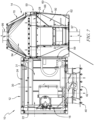
Fig. 1 is a front perspective view of an expandable environmental control unit (ECU) showing that the ECU includes a base section, a mobile section coupled to the base section, and a temperature control system coupled to the base section and the mobile section, and suggesting that the mobile section is arranged for movement between a collapsed-storage position, shown inFigs. 1 and 2 , and an expanded-use position, shown inFigs. 3 and 4 ; -
Fig. 2 is a rear perspective view of the ECU ofFig. 1 ; -
Fig. 3 is a view similar toFig. 1 showing the ECU in the expanded-use position with the mobile section extending from the base section; -
Fig. 4 is a rear perspective view of the ECU ofFig. 3 ; -
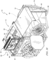
Fig. 5 is a perspective exploded assembly view of the ECU ofFig. 1 showing that the temperature control system includes a compressor and outdoor heat exchangers coupled to the base section and an expansion device and an indoor heat exchanger coupled to the mobile section for movement therewith relative to the base section; -
Fig. 6 is a section view taken along line 6-6 inFig. 1 showing the mobile section arranged within the base section in the collapsed-storage position; -
Fig. 7 is a section view taken along line 7-7 inFig. 3 showing the mobile section extending from the base section in the expanded-use position and suggesting that air flows into an air return of the mobile section, passes through the indoor heat exchanger of the temperature control system, and flows out of an air supply of the mobile section; -
Figs. 8-14 are a series of views illustrating an exemplary process for moving the ECU from the collapsed-storage position to the expanded-use position; -
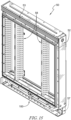
Fig. 15 is a perspective view of a carriage of the mobile section; -
Fig. 16 is a perspective view of an extendable strut of the air return of the mobile section showing a blower unit coupled to the strut for movement relative to the carriage between a stowed position, shown inFig. 16 , and deployed position, shown inFig. 17 ; -
Fig. 17 is a view similar toFig. 16 showing the strut in the extended position; -
Figs. 18-21 are a series of views illustrating an exemplary process for moving the strut from the retracted position to the extended position; -
Figs. 22-25 are a series of views illustrating an exemplary process for moving the air supply of the mobile section from a flattened position, shown inFigs. 12 and22 , to an erected position, shown inFigs. 14 and24 ; -
Fig. 26 is an enlarged view of the ECU ofFig. 1 showing a brace coupled to the mobile section and suggesting that an arm of the brace is movable between an unlocked position, shown inFigs. 26 and 27 , and a locked position, shown inFigs. 28 and 29 ; -
Fig. 27 is an enlarged view of the brace ofFig. 26 showing the arm in the unlocked position with a proximal end of the arm spaced apart from a platform of the base section to allow movement of the mobile section from the expanded-use position toward the collapsed-storage position; -
Fig. 28 is a view similar toFig. 26 showing the arm in the locked position; -
Fig. 29 is an enlarged view of the brace ofFig. 28 showing that the proximal end of the arm engages with the platform of the base section to block movement of the mobile section from the expanded-use position toward the collapsed-storage position; and -
Fig. 30 is a view similar toFig. 3 showing a control module of the ECU pivoted to a raised position relative to the base section. - The exemplification set out herein illustrates embodiments of the disclosure that are not to be construed as limiting the scope of the disclosure in any manner. Additional features of the present disclosure will become apparent to those skilled in the art upon consideration of the following detailed description of illustrative embodiments exemplifying modes of carrying out the disclosure as presently perceived.
- An illustrative expandable environmental control unit (ECU) 10 in accordance with the present disclosure is shown in
Figs. 1-4 . TheECU 10 includes abase section 12, amobile section 14 coupled to thebase section 12, and atemperature control system 16 coupled to thebase section 12 and themobile section 14. Themobile section 14 is arranged for movement relative to thebase section 12 between a collapsed-storage position, shown inFigs. 1 and 2 , and an expanded-use position, shown inFigs. 3 and 4 . TheECU 10 is arranged within a first footprint in the collapsed-storage position and is arranged in a larger second footprint in the expanded-use position. Themobile section 14 andtemperature control system 16 are contained within thebase section 12 in the collapsed-storage position (as shown inFig. 6 ) to minimize a footprint of theECU 10 for storage and transport. Themobile section 14 extends from thebase section 12 in the expanded-use position (as shown inFigs. 3 and 4 ) to provide air flow (as suggested inFig. 7 ) through an enclosed space, such as a building structure or temporary shelter. Exemplary processes for moving theECU 10 from the collapsed-storage position to the expanded-use position are illustrated inFigs. 8-14 and16-25 . Thetemperature control system 16 is configured to raise or lower a temperature of the air passing through themobile section 14 to provide heated or cooled air to the enclosed space. - In the illustrative embodiment, the
temperature control system 16 includes acompressor 21 andoutdoor heat exchangers base section 12 and anexpansion device 26 and anindoor heat exchanger 28 coupled to themobile section 14 for movement therewith relative to thebase section 12 as shown inFig. 5 . Theoutdoor heat exchangers indoor heat exchanger 28 is arranged to exchange heat with air flowing through themobile section 14 to provide heated or cooled air to the enclosed space. Thecompressor 21 andoutdoor heat exchangers expansion device 26 andindoor heat exchanger 28 bylines valve 27 is configured to selectively control a direction of flow of the working fluid through thetemperature control system 16 to allow heating or cooling of theindoor heat exchanger 28 in order to heat or cool the air passing through themobile section 14. In some embodiments, the reversingvalve 27 is omitted such that the ECU 10 operates solely as an air conditioner (for cooling air passing through the mobile section 14) or heat pump (for heating air passing through the mobile section 14). In some embodiments, other arrangements of thetemperature control system 16 are contemplated. For example, one of theoutdoor heat exchangers temperature control system 16 could be flipped with theexpansion device 26 andindoor heat exchanger 28 coupled to thebase section 12 and thecompressor 21 and one or more of theoutdoor heat exchangers mobile section 14. In some embodiments, theoutdoor heat exchangers indoor heat exchanger 28 from a collapsed-storage position to an expanded-use position. - As shown in
Fig. 5 , theexemplary base section 12 includes ahousing 30 and afan assembly 40 coupled to thehousing 30. Themobile section 14 includes acarriage 50, anair return 60 coupled to thecarriage 50, and anair supply 70 coupled to thecarriage 50 opposite from theair return 60. Thetemperature control system 16 is coupled to thehousing 30 andcarriage 50. Thecarriage 50 is arranged for movement relative to thehousing 30, and theair return 60 andair supply 70 are arranged for movement relative to thecarriage 50 to move theECU 10 between the collapsed-storage and expanded-use positions. Thefan assembly 40 is configured to pull air through theoutdoor heat exchangers plenum 31 of thehousing 30 to promote heat transfer between the air and theoutdoor heat exchangers Fig. 7 . The air passes out of theplenum 31 through thefan assembly 40. Theair return 60 is configured to pull air from the enclosed space (such as through a return conduit 97) into aplenum 92 of theair return 60, push the air through theindoor heat exchanger 28 into aplenum 94 of theair supply 70 to promote heat transfer between theindoor heat exchanger 28 and the air to heat or cool the air, and force the heated or cooled air out of theair supply 70 and back to the enclosed space (such as through a supply conduit 99). The air flow through theplenum 31 is separate from the air flow through theplenums - The
housing 30 of thebase section 12 includes a plurality ofposts 32 coupled to aplatform 34 and alid 36 coupled to theposts 32 opposite from theplatform 34 as shown inFig. 5 . Aflexible panel 38 is coupled to thehousing 30 and is configured to move between a closed position covering a side of thehousing 30, as shown inFig. 8 , and an opened position extending away from thehousing 30, as shown inFigs. 3 and 4 . In the closed position, thepanel 38 engages with thehousing 30 to block movement of themobile section 14 from the collapsed-storage position to the expanded-use position. Themobile section 14 can move to the expanded-use positon with thepanel 38 in the opened position. - In the illustrative embodiment, the
fan assembly 40 includes afan unit 42,clamp members rods 48 as shown inFig. 5 . Theclamp members fan unit 42, and therods 48 are coupled to thefan unit 42 and extend through theclamp members fan unit 42 relative to thehousing 30 between an inboard position substantially arranged within thehousing 30, shown inFigs. 1 and6 , and an outboard position extending away from thehousing 30, shown inFigs. 7 and8 . In some embodiments, linear bearings (not shown) are coupled to theclamp members rods 48 for sliding movement. In some embodiments, one ormore plates 41 are coupled to thefan unit 42 and one ormore magnets 43 are coupled to theclamp member 44 and/orclamp member 46 as shown inFig. 6 . Theplate 41 is formed from a magnetically attractive material, such as metal or another magnet, and themagnet 43 is arranged to bias theplate 41 toward themagnet 43 to hold thefan unit 42 in the outboard position. In some embodiments, themagnet 43 is coupled to thefan unit 42 and theplate 41 is coupled to theclamp member 44 and/or clampmember 46. One or more fasteners 45 (Fig. 8 ), such as quarter-turn fasteners, are coupled to thefan unit 42 and arranged to selectively engage with theclamp member 44 and/or clampmember 46 to hold thefan unit 42 in the inboard position. In some embodiments, a strap or handle 47 is coupled to thefan unit 42 to allow a user to move the fan unit from the inboard position to the outboard position. - The
carriage 50 of themobile section 14 includes aframe 52 andslide mechanisms frame 52 as shown inFig. 5 . Thecarriage 50 is movable between a stowed position, shown inFigs. 1 and6 , and a deployed position, shown inFigs. 7 ,11, and 12 . Theslide mechanisms rail members frame 52 relative to thehousing 30. Therail members housing 30 and therail members frame 52. In some embodiments, other mechanisms are used in place of theslide mechanisms slide mechanisms mobile section 14 relative to thebase section 12 and mount themobile section 14 on thehousing 30 or a separate stand. - In the illustrative embodiment, the
expansion device 26 andindoor heat exchanger 28 of thetemperature control system 16 are coupled to theframe 52 for movement therewith relative to thebase section 12, and thelines expansion device 26 andindoor heat exchanger 28 relative to other components of thetemperature control system 16 coupled to thebase section 12. In some embodiments, braces 58 are coupled to theframe 52 substantially aligned with theindoor heat exchanger 28 to provide mounting points for other components of themobile section 14, such as theair return 60, as shown inFigs. 5 and15 . Apanel 59 is coupled to theframe 52 and arranged to cover a side of thehousing 30 and form part of theplenum 31 with theECU 10 in the expanded-use position. In some embodiments, thepanel 59 is flexible and held in place relative to thehousing 30 using complementary magnetic strips or strips of hook and loop material along the perimeter of thepanel 59. - In the illustrative embodiment, the
air return 60 includes ablower unit 62 coupled to anextendable strut 64, and aflexible shroud 66 coupled to theblower unit 62 and to theframe 52 of thecarriage 50 to define theplenum 92 as shown inFigs. 5 and7 . Thestrut 64 allows selective movement of theblower unit 62 between a retracted position, shown inFig. 16 , and an extended position, shown inFig. 17 , relative to thecarriage 50. Theflexible shroud 66 moves with theblower unit 62 as suggested inFigs. 11 and 13 . - The
extendable strut 64 includes a pair of spaced apartbrackets 61 and corresponding pairs ofslide mechanisms brackets 61 as shown inFigs. 16 and 17 . Theblower unit 62 is coupled to theslide mechanisms brackets 61. In some embodiments, theslide mechanisms slide mechanisms blower unit 62 relative to thebrackets 61. Thebrackets 61 are coupled to thebraces 58 of thecarriage 50. - As shown in
Figs. 18-21 , alatch 68 of thestrut 64 controls movement of theblower unit 62 between the extended and retracted positions. Thelatch 68 is mounted for rotation about apivot 67, such as a fastener, between a stay position, shown inFigs. 18 and20 , and a release position, shown inFigs. 19 and21 .Tabs 69 extend laterally from thelatch 68 to engage with theslide mechanism 65 to block movement of theblower unit 62 with thelatch 68 in the stay position. A user can move thelatch 68 to the release positon and grab a strap or handle 91 coupled to theblower unit 62 to move theblower unit 62 to the extended position as suggested inFigs. 18-20 . Thelatch 68 is moved to the stay position to block movement of theblower unit 62 from the extended position toward the retracted position as shown inFig. 21 . In some embodiments, a biasing element (not shown), such as a spring, can bias thelatch 68 toward the stay position. In some embodiments, acoupling 93 is formed on theblower unit 62 for attachment of areturn conduit 97. Various forms of attachment are possible, and the present disclosure is not limited to thecoupling 93 shown. - In the illustrative embodiment, the
air supply 70 includes aflexible shroud 72 coupled to thecarriage 50, ahanger 74 coupled to theshroud 72, and a plurality offlaps carriage 50. Theair supply 70 is movable between a flattened position, shown inFigs. 12 and22 , to an erected position, shown inFigs. 14 and24 . Theflaps hanger 74 in the erected position. Theshroud 72,hanger 74, and flaps 71, 73, 75 extend along thecarriage 50 in the flattened position and extend away from thecarriage 50 in the erected position. An exemplary process for moving theair supply 70 from the flattened position to the erected position is illustrated inFigs. 22-25 . With themobile section 14 in the expanded-use position, theflaps shroud 72 as suggested inFigs. 22 and 23 . Thehanger 74 is moved away from thecarriage 50 to extend theshroud 72 and define theplenum 94 as suggested inFigs. 23 and24 . Theflaps shroud 72 and thehanger 74 is mounted on theflaps Figs. 24 and 25 . Theflap 71 is pivoted toward theflaps Fig. 4 . In some embodiments, theflap 71 engages with theflaps hanger 74 from being removed from theflaps flaps hanger 74. In some embodiments, a coupling is formed on thehanger 74 for attachment of asupply conduit 99. Various forms of attachment are possible, and the present disclosure is not limited to any particular coupling. - As shown in
Fig. 5 , acontrol module 80 is coupled to thebase section 12. Theexemplary control module 80 includes acontroller 82 mounted in acase 84. Thecontroller 82 is configured to control operation of theECU 10. Auser interface 86 is arranged on thecase 84 and is accessible through thehousing 30 of thebase section 12 to allow a user to operate theECU 10. Apower cable 88 can be stored within thebase section 12 during transport and removed to connect thecontrol module 80 with a power source, such as a generator. In some embodiments, thecase 84 is pivotally coupled to thehousing 30 by ahinge 81 to allow thecontrol module 80 to be moved to a raised position as shown inFig. 30 , such as for service or maintenance. In some embodiments, alatch 83 coupled to thecase 84 is configured to slide relative to thecase 84 and engage with thehousing 30 to hold thecontrol module 80 in the raised position. In some embodiments, a heater 89 is coupled to thecarriage 50. - In the illustrative embodiment, a
brace 100 is coupled to themobile section 14 as shown inFigs. 26-29 . Theexemplary brace 100 includes anarm 102 coupled to thecarriage 50 by apivot 104, such as a fastener, for rotation about thepivot 104 relative to thecarriage 50. Thearm 102 defines adistal end 101 extending away from thebase section 12 and aproximal end 103 arranged toward thebase section 12. One ormore pins 106 are coupled to thecarriage 50 and extend through thearm 102. Thepins 106 engage with thearm 102 to limit pivoting and lateral movement of thearm 102. Thearm 102 is movable between an unlocked position, shown inFigs. 26 and 27 , and a locked position, shown inFigs. 28 and 29 . In the unlocked position, theproximal end 103 of thearm 102 is spaced apart from theplatform 34 of thehousing 30 to allow movement of themobile section 14 from the expanded-use position toward the collapsed-storage position. In the locked position, theproximal end 103 of thearm 102 engages with theplatform 34 to block movement of themobile section 14 from the expanded-use position toward the collapsed-storage position. Thebrace 100 also limits bending loads placed on theslide mechanisms arm 102 engages with theplatform 34 in the locked position and thepins 106 engage with thearm 102 and thecarriage 50 to distribute at least a portion of the load on theslide mechanisms mobile section 14 through thearm 102 to theplatform 34. A biasing member, such as a spring, is coupled to thecarriage 50 and thearm 102 to bias thearm 102 toward the locked position. A user can engage with thedistal end 101 of thearm 102, such as by stepping on thedistal end 101, to move thearm 102 to the unlocked position and allow movement of themobile section 14 from the expanded-use position toward the collapsed-storage position. - An exemplary process for moving the
ECU 10 from the collapsed-storage position to the expanded-use position is illustrated inFigs. 1-4 and7-14 . Thefan unit 42 of thefan assembly 40 is moved from the inboard position, shown inFig. 1 , to the outboard position, shown inFig. 7 . Thecarriage 50 of themobile section 14 is moved from the stowed position to the deployed position, as suggested inFigs. 7-12 , to define theplenum 31 of thehousing 30. Theair return 60 is moved from the retracted position to the extended position to define theplenum 92, as suggested inFig. 13 , and theair supply 70 is moved from the flattened position to the erected position to define theplenum 94, as suggested inFig. 14 . - The exemplary
expandable ECU 10 allows for large outdoor heat exchangers and indoor heat exchangers to be used, thereby maximizing efficiency and capacity of thetemperature control system 16 and minimizing energy and fuel consumption. TheECU 10 also minimizes the footprint required for transport and storage. TheECU 10 provides separate large plenums for airflow through the outdoor heat exchangers and indoor heat exchangers, further maximizing capacity and efficiency of thetemperature control system 16. The arrangement of thebase section 12 andmobile section 14 allow for easy access to and replacement of components. Use of various materials for the components in theECU 10 are contemplated by the present disclosure, such as metals, plastics, fabrics, sheets, and films. - While the present disclosure describes various exemplary embodiments, the disclosure is not so limited. To the contrary, the disclosure is intended to cover various modifications, uses, adaptations, and equivalent arrangements based on the principles disclosed. Further, this application is intended to cover such departures from the present disclosure as come within at least the known or customary practice within the art to which it pertains. It is envisioned that those skilled in the art may devise various modifications and equivalent structures and functions without departing from the spirit and scope of the disclosure as recited in the following claims. The scope of the following claims is to be accorded the broadest interpretation to encompass all such modifications and equivalent structures and functions.
- Particular aspects of the present disclosure are given in the followings:
- 1. An environmental control unit comprising:
- a base section;
- a mobile section coupled to the base section for movement between a collapsed-storage position arranged substantially within the base section and an expanded-use position extending from the base section, preferably to allow separate air flows through the base section and the mobile section during operation of the environmental control unit; and
- a temperature control system coupled to the base section and the mobile section, the temperature control system configured to selectively heat or cool air flowing through the mobile section,
- wherein an indoor heat exchanger of the temperature control system is coupled to the mobile section and an outdoor heat exchanger of the temperature control system is coupled to the base section, and the indoor heat exchanger is arranged for movement with the mobile section relative to the outdoor heat exchanger and/or
- wherein the environmental control unit is arranged within a first footprint in the collapsed-storage position, and the environmental control unit is arranged within a larger second footprint in the expanded-use position.
- 2. The environmental control unit of
aspect 1, wherein the mobile section includes a carriage coupled to the base section for movement between a stowed position corresponding to the collapsed-storage position and a deployed position corresponding to the expanded-use position, an air return coupled to the carriage for movement with the carriage relative to the base section, and an air supply coupled to the carriage opposite of the air return for movement with the carriage relative to the base section, wherein the air return is movable between a retracted position and an extended position relative to the carriage, and wherein the air supply is movable between a flattened position and an erected position relative to the carriage. - 3. The environmental control unit according to any of the proceeding aspects, in particular according to aspect 2, wherein the carriage includes a frame and a slide mechanism coupled to the frame and to the base section to guide movement of the carriage between the stowed and deployed positions.
- 4. The environmental control unit according to any of the proceeding aspects, in particular according to aspect 3, wherein the temperature control system further comprises an expansion device and a compressor coupled with the indoor and outdoor heat exchangers to define a circuit for a working fluid, wherein the expansion device and indoor heat exchanger are coupled to the frame, and wherein the compressor and outdoor heat exchanger are coupled to the base section.
- 5. The environmental control unit according to any of the proceeding aspects, in particular according to aspect 2, wherein the air return includes a blower unit coupled to an extendable strut and a flexible shroud coupled to the blower unit and to the carriage, wherein the extendable strut is coupled to the carriage and configured to guide movement of the blower unit relative to the carriage for movement of the air return between the retracted and extended positions, and wherein the blower unit is configured to drive air flow through the indoor heat exchanger to promote heat transfer between the indoor heat exchanger and the air.
- 6. The environmental control unit according to any of the proceeding aspects, in particular according to aspect 5, wherein the extendable strut includes a bracket and a slide mechanism coupled to the bracket, wherein the blower unit is coupled to the slide mechanism of the extendable strut, and wherein the bracket is coupled to the carriage, the environmental control unit preferably further comprising a latch coupled to the extendable strut, wherein the latch is movable between a stay position and a release position relative to the extendable strut, wherein in the stay position the latch is configured to engage with the slide mechanism to block movement of the air return between the extended and retracted positions, and wherein in the release position the latch is configured to allow movement of the air return between the extended and retracted positions.
- 7. The environmental control unit according to any of the proceeding aspects, in particular according to aspect 2, wherein the air supply includes a flexible shroud coupled to the carriage, a hanger coupled to the shroud, and a flap pivotally coupled to the carriage, and wherein the shroud, hanger, and flap extend along the carriage in the flattened position and extend away from the carriage in the erected position, the hanger preferably being mounted on the flap in the erected position.
- 8. The environmental control unit according to any of the proceeding aspects, in particular according to
aspect 1, further comprising a fan assembly coupled to the base section, wherein the fan assembly is configured to pull air through the outdoor heat exchanger to promote heat transfer between the air and the outdoor heat exchanger, wherein the fan assembly includes a fan unit, clamp members, and rods, wherein the clamp members extend around the fan unit, wherein the rods are coupled to the fan unit and extend through the clamp members to allow sliding movement of the fan unit relative to the base section between an inboard position arranged substantially within the base section and an outboard position extending away from the base section. - 9. An environmental control unit, preferably an environmental control unit according to any of the proceeding aspects, comprising:
- a base section;
- a mobile section coupled to the base section for movement between a collapsed-storage position arranged substantially within the base section and an expanded-use position extending from the base section, the mobile section including a carriage coupled to the base section for movement between a stowed position corresponding to the collapsed-storage position and a deployed position corresponding to the expanded-use position, an air return coupled to the carriage for movement with the carriage relative to the base section, and an air supply coupled to the carriage opposite of the air return for movement with the carriage relative to the base section; and
- a temperature control system coupled to the base section and the mobile section, the temperature control system configured to selectively heat or cool air flowing through the mobile section,
- wherein movement of the carriage from the stowed position to the deployed position defines a first plenum within the base section to allow air flow through an outdoor heat exchanger coupled to the base section, and
- wherein movement of the air return from a retracted position to an extended position relative to the carriage defines a second plenum and movement of the air supply from a flattened position to an erected position relative to the carriage defines a third plenum to allow air flow through an indoor heat exchanger coupled to the mobile section.
- 10. The environmental control unit according to any of the proceeding aspects, in particular according to aspect 9, wherein the carriage includes a frame and a slide mechanism coupled to the frame and to the base section to guide movement of the carriage between the stowed and deployed positions and/or wherein the air return includes a blower unit coupled to an extendable strut and a flexible shroud coupled to the blower unit and to the carriage, wherein the extendable strut is coupled to the carriage and configured to guide movement of the blower unit relative to the carriage for movement of the air return between the retracted and extended positions, and wherein the blower unit is configured to drive air flow through the second and third plenums.
- 11. The environmental control unit according to any of the proceeding aspects, in particular according to
aspect 10, wherein the extendable strut includes a bracket and a slide mechanism coupled to the bracket, wherein the blower unit is coupled to the slide mechanism of the extendable strut, and wherein the bracket is coupled to the carriage. - 12. The environmental control unit according to any of the proceeding aspects, in particular according to aspect 9, wherein the air supply includes a flexible shroud coupled to the carriage, a hanger coupled to the shroud, and a flap pivotally coupled to the carriage, and wherein the shroud, hanger, and flap extend along the carriage in the flattened position and extend away from the carriage in the erected position, and wherein the hanger is mounted on the flap in the erected position.
- 13. The environmental control unit according to any of the proceeding aspects, in particular according to aspect 9, further comprising a fan assembly coupled to the base section, wherein the fan assembly is configured to pull air through the first plenum.
- 14. The environmental control unit according to any of the proceeding aspects, in particular according to aspect 13 wherein the fan assembly includes a fan unit, clamp members, and rods, wherein the clamp members extend around the fan unit, wherein the rods are coupled to the fan unit and extend through the clamp members to allow sliding movement of the fan unit relative to the base section between an inboard position arranged substantially within the base section and an outboard position extending away from the base section.
- 15. The environmental control unit according to any of the proceeding aspects, in particular according to
aspect 14, wherein the temperature control system includes an outdoor heat exchanger and an indoor heat exchanger, wherein the outdoor heat exchanger is coupled to the base section, and wherein the indoor heat exchanger is coupled to the mobile section for movement with the mobile section relative to the outdoor heat exchanger.
Claims (7)
- An environmental control unit comprising:a base section;a mobile section coupled to the base section for movement between a collapsed-storage position arranged substantially within the base section and an expanded-use position extending from the base section, the mobile section including a carriage coupled to the base section for movement between a stowed position corresponding to the collapsed-storage position and a deployed position corresponding to the expanded-use position, an air return coupled to the carriage for movement with the carriage relative to the base section, and an air supply coupled to the carriage opposite of the air return for movement with the carriage relative to the base section; anda temperature control system coupled to the base section and the mobile section, the temperature control system configured to selectively heat or cool air flowing through the mobile section,wherein movement of the carriage from the stowed position to the deployed position defines a first plenum within the base section to allow air flow through an outdoor heat exchanger coupled to the base section, andwherein movement of the air return from a retracted position to an extended position relative to the carriage defines a second plenum and movement of the air supply from a flattened position to an erected position relative to the carriage defines a third plenum to allow air flow through an indoor heat exchanger coupled to the mobile section.
- The environmental control unit of claim 1, wherein the carriage includes a frame and a slide mechanism coupled to the frame and to the base section to guide movement of the carriage between the stowed and deployed positions.
- The environmental control unit of claim 1, wherein the air return includes a blower unit coupled to an extendable strut and a flexible shroud coupled to the blower unit and to the carriage, wherein the extendable strut is coupled to the carriage and configured to guide movement of the blower unit relative to the carriage for movement of the air return between the retracted and extended positions, and wherein the blower unit is configured to drive air flow through the second and third plenums.
- The environmental control unit of claim 3, wherein the extendable strut includes a bracket and a slide mechanism coupled to the bracket, wherein the blower unit is coupled to the slide mechanism of the extendable strut, and wherein the bracket is coupled to the carriage.
- The environmental control unit of claim 1, wherein the air supply includes a flexible shroud coupled to the carriage, a hanger coupled to the shroud, and a flap pivotally coupled to the carriage, and wherein the shroud, hanger, and flap extend along the carriage in the flattened position and extend away from the carriage in the erected position, and wherein the hanger is mounted on the flap in the erected position.
- The environmental control unit of claim 1, further comprising a fan assembly coupled to the base section, wherein the fan assembly is configured to pull air through the first plenum.
- The environmental control unit of claim 6, wherein the fan assembly includes a fan unit, clamp members, and rods, wherein the clamp members extend around the fan unit, wherein the rods are coupled to the fan unit and extend through the clamp members to allow sliding movement of the fan unit relative to the base section between an inboard position arranged substantially within the base section and an outboard position extending away from the base section.
Applications Claiming Priority (2)
| Application Number | Priority Date | Filing Date | Title |
|---|---|---|---|
| US17/385,306 US11920804B2 (en) | 2021-07-26 | 2021-07-26 | Expandable environmental control unit |
| EP22186646.0A EP4124804B1 (en) | 2021-07-26 | 2022-07-25 | Expandable environmental control unit |
Related Parent Applications (2)
| Application Number | Title | Priority Date | Filing Date |
|---|---|---|---|
| EP22186646.0A Division-Into EP4124804B1 (en) | 2021-07-26 | 2022-07-25 | Expandable environmental control unit |
| EP22186646.0A Division EP4124804B1 (en) | 2021-07-26 | 2022-07-25 | Expandable environmental control unit |
Publications (2)
| Publication Number | Publication Date |
|---|---|
| EP4421402A2 true EP4421402A2 (en) | 2024-08-28 |
| EP4421402A3 EP4421402A3 (en) | 2024-10-30 |
Family
ID=82703140
Family Applications (2)
| Application Number | Title | Priority Date | Filing Date |
|---|---|---|---|
| EP24187752.1A Pending EP4421402A3 (en) | 2021-07-26 | 2022-07-25 | Expandable environmental control unit |
| EP22186646.0A Active EP4124804B1 (en) | 2021-07-26 | 2022-07-25 | Expandable environmental control unit |
Family Applications After (1)
| Application Number | Title | Priority Date | Filing Date |
|---|---|---|---|
| EP22186646.0A Active EP4124804B1 (en) | 2021-07-26 | 2022-07-25 | Expandable environmental control unit |
Country Status (12)
| Country | Link |
|---|---|
| US (2) | US11920804B2 (en) |
| EP (2) | EP4421402A3 (en) |
| JP (1) | JP2023017731A (en) |
| CN (1) | CN115682171A (en) |
| AU (1) | AU2022204818A1 (en) |
| CA (1) | CA3168183A1 (en) |
| ES (1) | ES2995118T3 (en) |
| IL (1) | IL294798B1 (en) |
| MX (2) | MX2022009175A (en) |
| PL (1) | PL4124804T3 (en) |
| SA (1) | SA122431397B1 (en) |
| ZA (1) | ZA202208266B (en) |
Families Citing this family (2)
| Publication number | Priority date | Publication date | Assignee | Title |
|---|---|---|---|---|
| US11920804B2 (en) * | 2021-07-26 | 2024-03-05 | Aar Manufacturing, Inc. | Expandable environmental control unit |
| EP4621301A1 (en) * | 2024-03-19 | 2025-09-24 | Kenneth Asplund | Portable construction site heat pump system |
Family Cites Families (25)
| Publication number | Priority date | Publication date | Assignee | Title |
|---|---|---|---|---|
| US2362698A (en) * | 1934-10-24 | 1944-11-14 | Gen Motors Corp | Refrigerating apparatus |
| US2251960A (en) * | 1936-06-01 | 1941-08-12 | Gen Motors Corp | Refrigerating apparatus |
| US2994211A (en) * | 1959-04-06 | 1961-08-01 | Whirlpool Co | Home appliance |
| US3498079A (en) * | 1969-02-04 | 1970-03-03 | Kramer Trenton Co | Refrigeration or air conditioning system for installation partly without and partly within an existing building |
| US3740964A (en) * | 1971-06-14 | 1973-06-26 | Tomeco Inc | Portable air conditioner |
| US3802216A (en) * | 1971-09-24 | 1974-04-09 | Texas Eng Sales Co | Portable air conditioner and heating unit |
| US3777506A (en) * | 1972-05-08 | 1973-12-11 | Camper Comfort Corp | Portable air conditioner apparatus |
| US5685165A (en) * | 1996-07-12 | 1997-11-11 | Bigelow, Jr.; Floyd E. | Portable air conditioning system |
| US6418744B1 (en) * | 2001-04-09 | 2002-07-16 | Earnest J. Neal | Method and apparatus for containing an ambient climate control system |
| US6662588B2 (en) | 2001-05-14 | 2003-12-16 | Vantage Equipment Corp. | Modular liquid-cooled air conditioning system |
| CN1740658A (en) | 2004-08-24 | 2006-03-01 | 乐金电子(天津)电器有限公司 | Window type air conditioner |
| US7481869B2 (en) * | 2005-08-17 | 2009-01-27 | Andrew Llc | Dry gas production systems for pressurizing a space and methods of operating such systems to produce a dry gas stream |
| DE202008002972U1 (en) | 2008-03-01 | 2008-07-17 | Trox Gmbh | Connection box for a duct system of a ventilation or air conditioning system |
| US20100227542A1 (en) * | 2009-03-09 | 2010-09-09 | Richard Goldmann | Apparatus for cooling an exerciser for use with an exercise machine |
| KR101781845B1 (en) | 2010-05-13 | 2017-09-26 | 엘지전자 주식회사 | Indoor unit of air conditioner |
| EP2428743A1 (en) | 2010-09-10 | 2012-03-14 | TROX GmbH | Connection cabinet for a canal system of an ambient air or air conditioning facility |
| EP3076089A1 (en) | 2015-04-01 | 2016-10-05 | Zhendre | Modular movable air-conditioner architecture |
| CN206771555U (en) | 2017-04-10 | 2017-12-19 | 广东美的制冷设备有限公司 | A kind of mobile air conditioner |
| US20180356124A1 (en) | 2017-06-09 | 2018-12-13 | Johnson Controls Technology Company | Movable heat exchanger |
| US11085666B2 (en) | 2018-05-22 | 2021-08-10 | Johnson Controls Technology Company | Collapsible roof top unit systems and methods |
| CN111912032B (en) * | 2019-05-09 | 2025-02-18 | 青岛海尔空调器有限总公司 | A saddle-type window air conditioner |
| US11226116B2 (en) * | 2019-08-28 | 2022-01-18 | Haier Us Appliance Solutions, Inc. | Air conditioning appliance and telescoping air plenum with self-adjusting divider |
| CN110631156B (en) * | 2019-11-11 | 2024-08-09 | 杰马科技(中山)有限公司 | Temperature-regulating fan capable of being packaged in folding mode and folding method thereof |
| US11655999B2 (en) * | 2020-06-22 | 2023-05-23 | Robert Bosch Llc | Environmental control unit |
| US11920804B2 (en) * | 2021-07-26 | 2024-03-05 | Aar Manufacturing, Inc. | Expandable environmental control unit |
-
2021
- 2021-07-26 US US17/385,306 patent/US11920804B2/en active Active
-
2022
- 2022-07-05 AU AU2022204818A patent/AU2022204818A1/en active Pending
- 2022-07-17 IL IL294798A patent/IL294798B1/en unknown
- 2022-07-19 CA CA3168183A patent/CA3168183A1/en active Pending
- 2022-07-22 JP JP2022116906A patent/JP2023017731A/en active Pending
- 2022-07-24 SA SA122431397A patent/SA122431397B1/en unknown
- 2022-07-25 PL PL22186646.0T patent/PL4124804T3/en unknown
- 2022-07-25 ES ES22186646T patent/ES2995118T3/en active Active
- 2022-07-25 ZA ZA2022/08266A patent/ZA202208266B/en unknown
- 2022-07-25 MX MX2022009175A patent/MX2022009175A/en unknown
- 2022-07-25 MX MX2025009093A patent/MX2025009093A/en unknown
- 2022-07-25 EP EP24187752.1A patent/EP4421402A3/en active Pending
- 2022-07-25 EP EP22186646.0A patent/EP4124804B1/en active Active
- 2022-07-26 CN CN202210884731.1A patent/CN115682171A/en active Pending
-
2024
- 2024-03-01 US US18/593,241 patent/US20240200796A1/en active Pending
Also Published As
| Publication number | Publication date |
|---|---|
| MX2022009175A (en) | 2023-01-27 |
| SA122431397B1 (en) | 2024-04-25 |
| AU2022204818A1 (en) | 2023-02-09 |
| IL294798A (en) | 2023-02-01 |
| US20230021790A1 (en) | 2023-01-26 |
| CA3168183A1 (en) | 2023-01-26 |
| MX2025009093A (en) | 2025-09-02 |
| EP4124804B1 (en) | 2024-09-04 |
| IL294798B1 (en) | 2025-12-01 |
| EP4421402A3 (en) | 2024-10-30 |
| US11920804B2 (en) | 2024-03-05 |
| EP4124804A1 (en) | 2023-02-01 |
| CN115682171A (en) | 2023-02-03 |
| US20240200796A1 (en) | 2024-06-20 |
| ZA202208266B (en) | 2023-04-26 |
| JP2023017731A (en) | 2023-02-07 |
| ES2995118T3 (en) | 2025-02-06 |
| PL4124804T3 (en) | 2025-01-27 |
Similar Documents
| Publication | Publication Date | Title |
|---|---|---|
| US20240200796A1 (en) | Expandable environmental control unit | |
| US12246402B2 (en) | Window installation system and method for split-architecture air conditioning unit | |
| JP6716685B2 (en) | Computer server thermal conditioning utilizing integrated precision airflow | |
| US10724761B2 (en) | Modular heat transfer units | |
| US5562091A (en) | Mobile ventilator capable of nesting within and docking with a hospital bed base | |
| US10502445B2 (en) | Wall-mount air conditioner and method involving same | |
| US20120077428A1 (en) | Air cooling of medium voltage drive components | |
| WO2005119410A2 (en) | Systems and mehtods for cooling computer modules in computer cabinets | |
| US5199461A (en) | Fluid distribution valve | |
| EP3452313B1 (en) | Refrigeration unit having movable directional element | |
| JP2007132629A (en) | Air conditioner for temporary facility | |
| US8857202B1 (en) | High density modular integrated cooling system and methods of operation thereof | |
| CN215733011U (en) | Heat dissipation formula low-voltage switchgear | |
| CN212645107U (en) | Drying and disinfection room | |
| CN214172427U (en) | Compact independent drive movable aircraft ground air conditioning unit | |
| JP2024148583A (en) | Spot Air Conditioning Booth | |
| CN222117165U (en) | Unmanned aerial vehicle hangar | |
| NL2000156C2 (en) | Heating, cooling and air circulation device for stable buildings. | |
| CN214282643U (en) | Energy-conserving ventilation unit of pig house | |
| CN111457687A (en) | Drying and disinfection room | |
| JP3273552B2 (en) | Air conditioner for air conditioning system using heat storage | |
| CN117739424A (en) | Machine room air conditioner and control method thereof | |
| JPH0278838A (en) | Air conditioner | |
| JP2000018667A (en) | Heat exchange ventilator and structure with heat exchange ventilator | |
| JPH04307993A (en) | Electronic computer |
Legal Events
| Date | Code | Title | Description |
|---|---|---|---|
| PUAI | Public reference made under article 153(3) epc to a published international application that has entered the european phase |
Free format text: ORIGINAL CODE: 0009012 |
|
| STAA | Information on the status of an ep patent application or granted ep patent |
Free format text: STATUS: THE APPLICATION HAS BEEN PUBLISHED |
|
| AC | Divisional application: reference to earlier application |
Ref document number: 4124804 Country of ref document: EP Kind code of ref document: P |
|
| AK | Designated contracting states |
Kind code of ref document: A2 Designated state(s): AL AT BE BG CH CY CZ DE DK EE ES FI FR GB GR HR HU IE IS IT LI LT LU LV MC MK MT NL NO PL PT RO RS SE SI SK SM TR |
|
| REG | Reference to a national code |
Ref country code: DE Ref legal event code: R079 Free format text: PREVIOUS MAIN CLASS: F24F0013320000 Ipc: F24F0001000300 |
|
| PUAL | Search report despatched |
Free format text: ORIGINAL CODE: 0009013 |
|
| AK | Designated contracting states |
Kind code of ref document: A3 Designated state(s): AL AT BE BG CH CY CZ DE DK EE ES FI FR GB GR HR HU IE IS IT LI LT LU LV MC MK MT NL NO PL PT RO RS SE SI SK SM TR |
|
| RIC1 | Information provided on ipc code assigned before grant |
Ipc: F24F 13/32 20060101ALI20240920BHEP Ipc: F24F 13/20 20060101ALI20240920BHEP Ipc: F24F 13/02 20060101ALI20240920BHEP Ipc: F24F 1/0003 20190101AFI20240920BHEP |
|
| STAA | Information on the status of an ep patent application or granted ep patent |
Free format text: STATUS: REQUEST FOR EXAMINATION WAS MADE |
|
| 17P | Request for examination filed |
Effective date: 20250408 |
|
| STAA | Information on the status of an ep patent application or granted ep patent |
Free format text: STATUS: EXAMINATION IS IN PROGRESS |
|
| 17Q | First examination report despatched |
Effective date: 20251016 |