EP4421380A1 - Reflector system for a recessed luminaire - Google Patents
Reflector system for a recessed luminaire Download PDFInfo
- Publication number
- EP4421380A1 EP4421380A1 EP23158665.2A EP23158665A EP4421380A1 EP 4421380 A1 EP4421380 A1 EP 4421380A1 EP 23158665 A EP23158665 A EP 23158665A EP 4421380 A1 EP4421380 A1 EP 4421380A1
- Authority
- EP
- European Patent Office
- Prior art keywords
- reflector
- recessed luminaire
- reflector system
- inner reflector
- light source
- Prior art date
- Legal status (The legal status is an assumption and is not a legal conclusion. Google has not performed a legal analysis and makes no representation as to the accuracy of the status listed.)
- Pending
Links
Images


Classifications
-
- F—MECHANICAL ENGINEERING; LIGHTING; HEATING; WEAPONS; BLASTING
- F21—LIGHTING
- F21V—FUNCTIONAL FEATURES OR DETAILS OF LIGHTING DEVICES OR SYSTEMS THEREOF; STRUCTURAL COMBINATIONS OF LIGHTING DEVICES WITH OTHER ARTICLES, NOT OTHERWISE PROVIDED FOR
- F21V31/00—Gas-tight or water-tight arrangements
- F21V31/005—Sealing arrangements therefor
-
- F—MECHANICAL ENGINEERING; LIGHTING; HEATING; WEAPONS; BLASTING
- F21—LIGHTING
- F21S—NON-PORTABLE LIGHTING DEVICES; SYSTEMS THEREOF; VEHICLE LIGHTING DEVICES SPECIALLY ADAPTED FOR VEHICLE EXTERIORS
- F21S8/00—Lighting devices intended for fixed installation
- F21S8/02—Lighting devices intended for fixed installation of recess-mounted type, e.g. downlighters
- F21S8/026—Lighting devices intended for fixed installation of recess-mounted type, e.g. downlighters intended to be recessed in a ceiling or like overhead structure, e.g. suspended ceiling
-
- F—MECHANICAL ENGINEERING; LIGHTING; HEATING; WEAPONS; BLASTING
- F21—LIGHTING
- F21V—FUNCTIONAL FEATURES OR DETAILS OF LIGHTING DEVICES OR SYSTEMS THEREOF; STRUCTURAL COMBINATIONS OF LIGHTING DEVICES WITH OTHER ARTICLES, NOT OTHERWISE PROVIDED FOR
- F21V17/00—Fastening of component parts of lighting devices, e.g. shades, globes, refractors, reflectors, filters, screens, grids or protective cages
- F21V17/10—Fastening of component parts of lighting devices, e.g. shades, globes, refractors, reflectors, filters, screens, grids or protective cages characterised by specific fastening means or way of fastening
- F21V17/101—Fastening of component parts of lighting devices, e.g. shades, globes, refractors, reflectors, filters, screens, grids or protective cages characterised by specific fastening means or way of fastening permanently, e.g. welding, gluing or riveting
-
- F—MECHANICAL ENGINEERING; LIGHTING; HEATING; WEAPONS; BLASTING
- F21—LIGHTING
- F21V—FUNCTIONAL FEATURES OR DETAILS OF LIGHTING DEVICES OR SYSTEMS THEREOF; STRUCTURAL COMBINATIONS OF LIGHTING DEVICES WITH OTHER ARTICLES, NOT OTHERWISE PROVIDED FOR
- F21V7/00—Reflectors for light sources
- F21V7/10—Construction
-
- F—MECHANICAL ENGINEERING; LIGHTING; HEATING; WEAPONS; BLASTING
- F21—LIGHTING
- F21V—FUNCTIONAL FEATURES OR DETAILS OF LIGHTING DEVICES OR SYSTEMS THEREOF; STRUCTURAL COMBINATIONS OF LIGHTING DEVICES WITH OTHER ARTICLES, NOT OTHERWISE PROVIDED FOR
- F21V17/00—Fastening of component parts of lighting devices, e.g. shades, globes, refractors, reflectors, filters, screens, grids or protective cages
- F21V17/10—Fastening of component parts of lighting devices, e.g. shades, globes, refractors, reflectors, filters, screens, grids or protective cages characterised by specific fastening means or way of fastening
- F21V17/14—Bayonet-type fastening
-
- F—MECHANICAL ENGINEERING; LIGHTING; HEATING; WEAPONS; BLASTING
- F21—LIGHTING
- F21Y—INDEXING SCHEME ASSOCIATED WITH SUBCLASSES F21K, F21L, F21S and F21V, RELATING TO THE FORM OR THE KIND OF THE LIGHT SOURCES OR OF THE COLOUR OF THE LIGHT EMITTED
- F21Y2115/00—Light-generating elements of semiconductor light sources
- F21Y2115/10—Light-emitting diodes [LED]
Definitions
- the invention relates to a recessed luminaire and a reflector system for such a recessed luminaire, whereas the reflector system provides - beside optical benefits - a certain protection for the recessed luminaire.
- Recessed luminaires are usually installed with their housing or base body inside a mounting hole, e.g. in a ceiling or wall. This means that the components accessible from the outside, such as the mounting ring and the glass pane of the recessed luminaire, are usually the most stressed components when it comes to protecting the recessed luminaire, especially from dust or water.
- recessed luminaires known so far have always tried to increasingly seal the contact to the supporting surface of the wall or ceiling on the one hand and to further protect the entire underside of the recessed luminaire - i.e. the side of the light emitting surface of the recessed luminaire - from external influences with respective sealing systems and other protective components.
- IP classification system is used to determine the level of protection provided by an electrical device against the ingress of foreign bodies (such as dust) and water/moisture.
- the IP classification system is important for ensuring that devices are suitable for use in specific environments and to ensure the safety and longevity of the device.
- the IP classification system consists of two digits. The first digit represents the level of protection against the ingress of solid foreign bodies, while the second digit represents the level of protection against the ingress of water/moisture. The higher the digits, the better the protection. For example, an IP-54 rated device is protected against dust and splashing water, while an IP-65 rated device is dust-tight and further protected against powerful jets of water.
- a recessed luminaire with an IP-54 rating is protected against dust and splashing water, making them suitable for use in environments where there may be a moderate amount of dust or splashing water present.
- These luminaires may be suitable for use in indoor areas such as kitchens or bathrooms.
- the IP-65 rated recessed luminaire has additional protection against dust, as the such rated luminaire is dust-tight, and has further protection against water jets. This makes the IP-65 rated recessed luminaire suitable for use in environments where there may be direct exposure to water - such as shower areas or outdoor environments or the like - or extensive dust - as (outdoor) construction zones or arid regions or the like.
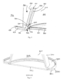
- Figure 5 displays an excerpt of a known recessed luminaire with a base body 9100 and a reflective surface 9211 on an inner side 9210 of the luminaire. Further, figure 5 shows a recessed luminaire with an elaborate protection system 9000, 9001, 9003, formed by an extra cover 9000 of the recessed luminaire, which overlaps the mounting frame 9127 of the recessed luminaire by means of a sealing cover 9001 and also has a glass plate 9003 as the light emitting surface of the recessed luminaire.
- the protection system 9000, 9001, 9003 which interact with the mounting frame 9127 of the recessed luminaire, and further overlaps of the cover 9001 and the glass plate 9003, a recessed luminaire with IP-54 classification is thus created.
- the invention is concerned with the task of providing a recessed luminaire that is particularly durable with respect to environmental influences.
- a reflector system for a recessed luminaire with a light emitting surface comprises:
- the recessed luminaire with the light emitting surface itself is provided.
- the recessed luminaire hereby comprises:
- the reflector As well as the inside of the reflector, as well as the components of a respective connected device body of a recessed luminaire, are protected particularly advantageously, lastingly and effectively against external influences.
- the inner reflector body is protected from external impacts, shocks and the like, whereas the protective plate prevents foreign bodies (water, moisture, dust, etc.) from entering the inner reflector body from the underside of the reflector system.
- the base body, and in particular the outer wall body, and the inner reflector body received in the inner receiving space together have a synergetic effect that makes it more difficult for water (or foreign bodies in general) to enter the recessed luminaire.
- the protective plate has optical elements disposed on the inner and/or on the outer side of the protective plate.
- optical elements disposed on the inner and/or on the outer side of the protective plate.
- the protective plate is irreversibly connected to the bottom surface of the inner reflector body by means of ultrasonic wave welding.
- the such configured reflector system, and in particular the connection between the protective plate and the inner reflector body is particular advantageous, effective and durable.
- a recessed luminaire which is equipped with such a reflector system can be used in various scenarios, even with high moisture and/or dust conditions.
- the sealing of the inner reflector body by the protective plate protects the inner side of the inner reflector body at least according to IP code IP-65.
- the recessed luminaire is protected by the reflector system at least according to IP code IP-65.
- the such configured reflector system respectively the such configured recessed luminaire is particularly advantageous.
- an air gap between the outer surface of the inner reflector body and the outer wall body as well as between the protective plate and the outer wall body.
- This air gap between the outer wall and the components arranged in the inner receiving space i.e., the inner reflector body and the protective plate
- generated heat e.g. generated by the device body of the recessed luminaire
- ambient air from the underside of the recessed luminaire is used for heat dissipation.
- the air gap has another symbiotic effect, namely water ingress is prevented by the capillarity of the above-mentioned components.
- the capillarity created by the distance between the outer surfaces of the above-mentioned components prevents water from penetrating deep into the reflector system and also promotes that the water can run off the reflector system. This is favoured in particular (depending on the installation direction of the recessed luminaire) by the gravitational force.
- the bottom end of the inner reflector body in the region of the bottom surface has over its entire circumference a projection extending outwardly, i.e. in the direction of the outer wall body.
- This circumferential projection of the inner reflector body has the advantage of increasing the stability and rigidity of the inner reflector body, while also creating a larger coupling surface with the protective plate, so that this connection is also strengthened by this configuration.
- the distance between the inner reflector body and the outer wall is reduced, so that the entry of foreign bodies into the gap is further reduced.
- the projection does not contact the outer wall, such that there is a gap in between.
- the projection provides a varying distance between the inner reflector body and the outer wall body.
- the effect of capillarity is further enhanced, thus preventing foreign bodies from entering the luminaire.
- This further improves the ejection of any foreign bodies, and the air circulation is also increased.
- the air circulation also favours that, for example, dust that has entered the luminaire is not collected inside the luminaire, but is removed from the luminaire.
- the varying distance is subsequent to the air gap, this further enhances the above standing effects.
- the varying distance is always greater than zero, meaning that there is no contact between the outer wall body and the inner reflector body.
- the varying distance becomes increasingly larger in the direction opposite to the light emitting direction, which further increases the capillarity.
- the largest jump in the distance between the inner reflector body and the outer wall is directly after the projection of the inner reflector body (viewed in the opposite light emitting direction).
- the step-like structure created by the projection further enhances the effect of capillarity.
- the distance between two surfaces affects the capillary action and thus the depth of water penetration.
- a larger distance between the surfaces generally favours a lower depth of water penetration, as capillary action decreases as the distance increases. This is because capillary action is caused by the adhesion of water to the walls of the capillary and the cohesion of water within the capillary.
- the attraction between the walls of the capillary and the water decreases, resulting in less water entering the joint - respectively the air gap of the reflector system.
- a distance between the inner reflector body and the outer wall body is smallest in the region of the projection.
- the such configured reflector system provides a particular efficient protection against foreign bodies (moisture, dust, water etc.), while simultaneously improving air circulation due to thermic effects and drain of water, for example.
- the distance between the projection of the inner reflector body and the outer wall body, and a distance between the protective plate and the outer wall body is substantially equal and constant.
- the air gap has a constant distance, which improves the drain capabilities of the reflector system, whereas deposits of foreign bodies in the area around the coupling of the inner reflector body and the protective plate are averted, improving functionality of a respective recessed luminaire.
- the inner reflector body is reversibly couplable to the base body.
- the inner reflector body has at least one coupling element on the side of the inner reflector body facing the light source receiving space for coupling with the base body.
- the base body has corresponding coupling elements for coupling the base body with the inner reflector body. This eases coupling of the two respective elements.
- the base body further comprises a light-transmitting end plate, for closing off the bottom side - i.e. the side, in the direction of the inner reflector body - of the light source receiving space.
- the end plate comprises on its face side the corresponding coupling elements for coupling the base body with the inner reflector body.
- the light-transmitting end plate comprises optical elements, which further improve light emission of the luminaire.
- the closure of the light source receiving space by the end plate protects the light source receiving space at least according to IP code IP-44.
- IP code IP-44 preferably according to IP-65 - a particularly protected and advantageous implementation of a recessed luminaire is formed.
- the outer wall body has an outwardly projecting flange on its side opposite to the light source receiving space.
- the outwardly projecting flange forms a mounting frame of a respective recessed luminaire.
- the reflective surface is realized by a white and/or silver paint and/or by reflective surface elements. This further improves the light emission properties of the luminaire, enabling particularly aesthetic, homogeneous and efficient light emission.
- the recessed luminaire has at least one anchor element for reversible mounting within a mounting hole, in particular a mounting hole of a ceiling, a wall or the like.
- the at least one anchor element is formed on the device body and/or on the reflector system - and here preferably on the base body - of the recessed luminaire. This enables particularly simple assembly and disassembly.
- Figure 1 shows an exemplary embodiment of a recessed luminaire 1 with a light emitting surface 301 having a reflector system 10 and a device body 700, which is coupled to the reflector system 10.
- a light emitting surface 301 having a reflector system 10
- a device body 700 which is coupled to the reflector system 10.
- the device body 700 may comprise further components such as a power unit or the like.
- the recessed luminaire 1 also has at least one anchor element 800 for reversible mounting within a mounting hole 900, in particular a mounting hole 900 of a ceiling 996, a wall or the like.
- the recessed luminaire 1 has two anchor elements 800, disposed on opposite sides of the device body 700, whereas it is also conceivable, that the at least one anchor element 800 is formed on the reflector system 10, or both on the reflector system 10 and the device body 700.
- the base body has a light source receiving space 110 for receiving the light source of the recessed luminaire 1.
- the light source receiving space 110 is formed by a surrounding receiving space wall 111, which laterally encompasses the light source receiving space 110.
- the base body 100 passes over a projection into the outer wall body 120, which extends in light emitting direction L substantially to the underside of the reflector system 10, or the recessed luminaire 1.
- the outer wall body 120 forms an outer shell of the reflector system 10, wherein the outer wall body 120 merges on its underside - i.e. the side visible to a user when the recessed luminaire 1 is installed - into an outwardly extending flange 127, which forms a typical mounting frame of a respective recessed luminaire 1.
- the shell-like structure of the outer wall body 120, as well as the flange 127 physically protect the inner reflector body 200, which is arranged on the inside of the base body 100, and components - such as the protective plate 300 - connected thereto.
- the outer wall 120 hereby forms an inner receiving space 121 inside the base body 100.
- the inner reflector body 200 is accommodated in this inner receiving space 121 and can preferably be reversibly coupled with the base body 100.
- the inner reflector body 200 is aligned flush with a light-transmitting end plate 130 of the base body 100 on its upper side.
- the end plate 130 closes off the bottom side of the light source receiving space 110, whereas this bottom side faces the inner reflector body 200.
- Protective glass plate 300 and internal reflector body 200 are ultrasonically welded and then form a unit, which is latched to the light-transmitting end plate 130 by means of latching lugs.
- the end plate 130 can also be glued.
- Other form-fit or force-fit couplings are also conceivable.
- the (reversible) coupling between base body 100 and inner reflector body 200 is achieved by means of at least one coupling element 250 of the inner reflector body 200 and corresponding coupling elements 140 of the base body 100, which can be arranged in particular on the light-transmitting end plate 130.
- the inner reflector body 200 has four coupling elements 250 on a top side of the inner reflector body 200, which faces the light source receiving space 110, for coupling with the base body 100.
- these corresponding coupling elements 140 can be arranged on the face side 131 of the light-transmitting end plate 130, as shown in Figure 2 .
- the inner reflector body 200 hereby has a reflective surface 211 on its inner side 210, which improves light guidance.
- the reflective surface 211 may be realized by a white and/or silver paint and/or by reflective surface elements.
- the translucent protective plate 300 is disposed in light emitting direction L on a bottom side / bottom surface 220 of the inner reflector body 200, such that the inner reflector body 200 is sealed on its bottom surface 220 with the protective plate 300.
- the protective plate 300 forms the light emitting surface 301 of the recessed luminaire 1.
- the protective plate 300 may have surface structures for special light extraction, whereby the translucent protective plate 300 may only be transparent to a limited extent or not at all.
- the protective plate 300 is irreversibly connected to the bottom surface 220 of the inner reflector body 200 by means of ultrasonic wave welding.
- the protective plate 300 may be glued or otherwise fixed to the inner reflector body 200, but ultrasonic welding has been found to provide a particularly durable, hard-wearing and tight coupling of the components.
- the sealing of the inner reflector body 200 by the protective plate 300 protects the inner side 210 of the inner reflector body 200 at least according to IP code IP-65.
- IP code IP-65 IP code
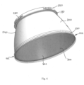
- the compound of the inner reflector body 200 and the protective glass plate 300 is displayed in Figure 6 .
- a circular element is present, whereas the at least one coupling element 250 is placed thereon.
- the at least one coupling element 250 is formed via snap-on / snap-in elements, which are coupled with the base body 100 when inserted therein.
- the shown coupling elements 250 interact with the light-transmitting end plate 130.
- the protective plate 300 extends to an outer edge of a projection 230 of the inner reflector body 200 and thus covers it flush from below.
- the outer surface 240 of the inner reflector body 200 extends from the coupling point with the protective plate 300 to an upper annular flange 290 on which the annular element with the at least one coupling element 250 is arranged.
- the upper annular flange 290 stabilises the upper area of the inner reflector body 200 and, in particular in combination with the outer wall body 120, forms a further protection against foreign bodies in this inner upper area of the reflector system 10, as can be seen in particular in Figure 2 .
- the inner reflector body 200 in the embodiments shown in Figures 1 to 4 has at its bottom end 222 (i.e., in the region of the bottom surface 220) over its entire circumference a projection 230 extending outwardly, i.e. in the direction of the outer wall body 120.
- This projection 230 which extends towards the outer wall body 120, offers an enlarged contact surface and thus coupling surface of the inner reflector body 200 with the protective plate 300.
- the recessed luminaire has an air gap 400 on its underside, which runs between the protective plate 300 and the outer wall body 120, as well as between the outer surface 240 of the inner reflector body 200 and the outer wall body 120, and in this case between the outer surface of the projection 230 and the outer wall body 120.
- the upper surface of the protective plate 300 has an essentially identical circumference as the inner reflector body 200 at its bottom surface 220.
- the protective plate 300 is adapted to the inner reflector body 200, respectively to its projection 230. Due to the projection 230 and the protective plate 300 adapted to the dimension of the projection 230, this air gap 400 is particularly narrow, whereby a gap is always present so that the outer wall body 120 does not come into contact with the protective plate 300 or the inner reflector body 120.
- the potential pressure of an incoming water jet working on the reflector system 10 is limited.
- a subsequent step-like recess 501 is provided with the projection 230, which creates a varying distance 500 between the inner reflector body 200, respective outer surface 240 of the inner reflector body 200, and the outer wall body 120.
- This recess 501, or the varying distance 500 abruptly creates a greater distance between the two components.
- the distance between the inner reflector body 200 and the outer wall body 120 changes constantly over the course of the outer surface 240 up to the upper end of the inner reflector body 200. It is also envisaged that this distance is greatest in an upper region of the inner reflector body 200.
- the varying distance 500 and the recess 501 is each subsequent to the air gap 400, whereas the varying distance 500 is always greater than zero.
- the distance between the inner reflector body 200 and the outer wall body 120 is smallest in the region of the projection 230. As further shown in detail in Figure 4 the distance between the projection 230 of the inner reflector body 200 and the outer wall body 120, and the distance between the protective plate 300 and the outer wall body 120 is substantially equal and constant.
- the design of an air gap 400 and the adjacent recess 501 or varying distance 500 uses the effects of capillarity between the surfaces of the inner reflector body 200 and the outer wall body 120, whereby, for example, water forced into the air gap 400 by a jet of water cannot fill the entire gap between the inner reflector body 200 and the outer wall body 120, but due to the capillarity - as described above - a further penetration, in particular a penetration beyond half of the inner reflector body 200 (preferably beyond one third of the height of the inner reflector body 200, particularly preferably beyond one quarter of the height of the inner reflector body 200), is prevented.
- the recessed luminaire 1 respectively the reflector system 10 provides sufficient proof against water jets, as no water accesses the inner components.
- the combination of the structural elements air gap 400, recess 501, or varying distance 500, up to the maximum distance between inner reflector body 200 and outer wall body 120 in an upper region of inner reflector body 200 symbiotically supports the effect of capillarity. Furthermore, the gravitational force - depending on the installation direction of the recessed luminaire 1 - also favours the drainage of foreign bodies that have entered the intermediate space. Heat generated by the operation of the recessed luminaire 1 is also dissipated particularly efficiently by means of the structure of the reflector system 1 presented here, whereby automatic ventilation of the reflector system 10 or the recessed luminaire 1 is created by the gap between the inner reflector body 200 and the outer wall body 120, as well as the air gap 400. These thermal effects also promote air circulation within the reflector system 10.
- the recessed luminaire 1 when the recessed luminaire 1 is installed in a mounting hole 900, for example a ceiling 996, the recessed luminaire 1 is sealed from the underside of the luminaire 1 by the protective plate 300, as can be seen in particular in Figures 1, 2 and 4 .
- Foreign bodies such as dust, water or moisture can therefore potentially only enter the space between the outer wall body 120 and the inner reflector body 200 of the reflector system 10 via the air gap 400, whereby the structure of the reflector system 10 favours the subsequent removal of these foreign bodies - as described above.
- the light source receiving space 110 is also sealed off by the end plate 130, whereby a tightness of IP-44 according to the IP classification is preferably achieved here.
- the structure of the reflector system 10 presented herein promotes the avoidance of so-called fogging of a luminaire due to accumulation of moisture on the light-emitting surface of the respective luminaire. Due to the sealed reflector system 10, respectively the recessed luminaire 1 according to the invention and the further preferred embodiments presented herein, such fogging is avoided even under adverse environmental conditions, such as high humidity and direct water irradiation.
- a beveled edge surface 126 forms the transition between frame-like flange 127 of base body 100 and outer wall body 120.
- this beveled edge surface 126 also has functional advantages.
- this edge surface 126 can also serve as an additional reflector surface on the outside. It also provides a guide surface to the air gap 400 between the protective plate 300 and the outer wall body 120, respectively between the inner reflector body 200 and the outer wall body 120, so that the air circulation in the space between the inner reflector body 200 and the outer wall 120 is improved overall.
- the beveled edge surface 126 also promotes water drainage from the space between the inner reflector body 200 and the outer wall 120 due to the direct contact with the air gap 400 as drainage.
- optical elements can also be provided on a surface (preferably the inner surface facing the inner side 210 of the inner reflector body 200) of the protective plate 300 for improved light emission.
- the reflector system 10 can be adapted to individual requirements of a user, whereby in particular it can be provided that differently designed protective plates 300 are available for different lighting scenarios, which can be exchanged together with the inner reflector body 200 depending on the situation.
- the reflector system 10 can also be coupled to the device body 700 by means of snap-in coupling elements 170 (or similar connecting elements) and is thus also reversibly connected to the latter. This enables particularly simple and cost-effective maintenance of the recessed luminaire.
- the recessed luminaire 1 can have a round or rectangular, in particular square, base surface, whereby the base surface is the side visible from an underside of the recessed luminaire 1 - i.e. the side visible to a user when the recessed luminaire 1 is installed.
- the base body 100 can be shaped essentially like a truncated pyramid or like a dome. Further, it is possible to produce the reflector system described here, or the recessed luminaire, in various shapes and sizes.
- the inner reflector body 200 is substantially dome-shaped.
- a particular advantageous recessed luminaire 1, respectively reflector system 10 thereof is accomplished, which has a particularly advantageous seal and thus particularly good durability and resistance.
- no sealing elements and components are required, yet a tighter system has been created.
- the maintainability and thermal performance of the luminaire has also been improved.
- the reflector system 10 described here can be used on existing recessed luminaires, i.e. that they are backwards compatible.
Landscapes
- Engineering & Computer Science (AREA)
- General Engineering & Computer Science (AREA)
- Arrangement Of Elements, Cooling, Sealing, Or The Like Of Lighting Devices (AREA)
Abstract
A reflector system (10) for a recessed luminaire (1) with a light emitting surface (301) and such a recessed luminaire (1) is provided. Hereby, the reflector system (10) comprises a base body (100), an inner reflector body (200), and a translucent protective plate (300) disposed on a bottom surface (220) of the inner reflector body (200). The inner reflector body (200) is sealed on its bottom surface (220) with the protective plate (300), wherein the protective plate (300) forms the light emitting surface (301) of a respective recessed luminaire (1).
Description
- The invention relates to a recessed luminaire and a reflector system for such a recessed luminaire, whereas the reflector system provides - beside optical benefits - a certain protection for the recessed luminaire.
- Recessed luminaires are usually installed with their housing or base body inside a mounting hole, e.g. in a ceiling or wall. This means that the components accessible from the outside, such as the mounting ring and the glass pane of the recessed luminaire, are usually the most stressed components when it comes to protecting the recessed luminaire, especially from dust or water.
- Therefore, recessed luminaires known so far have always tried to increasingly seal the contact to the supporting surface of the wall or ceiling on the one hand and to further protect the entire underside of the recessed luminaire - i.e. the side of the light emitting surface of the recessed luminaire - from external influences with respective sealing systems and other protective components.
- The so-called ingress protection (IP) classification system is used to determine the level of protection provided by an electrical device against the ingress of foreign bodies (such as dust) and water/moisture. The IP classification system is important for ensuring that devices are suitable for use in specific environments and to ensure the safety and longevity of the device. The IP classification system consists of two digits. The first digit represents the level of protection against the ingress of solid foreign bodies, while the second digit represents the level of protection against the ingress of water/moisture. The higher the digits, the better the protection. For example, an IP-54 rated device is protected against dust and splashing water, while an IP-65 rated device is dust-tight and further protected against powerful jets of water.
- For example a recessed luminaire with an IP-54 rating is protected against dust and splashing water, making them suitable for use in environments where there may be a moderate amount of dust or splashing water present. These luminaires may be suitable for use in indoor areas such as kitchens or bathrooms. The IP-65 rated recessed luminaire has additional protection against dust, as the such rated luminaire is dust-tight, and has further protection against water jets. This makes the IP-65 rated recessed luminaire suitable for use in environments where there may be direct exposure to water - such as shower areas or outdoor environments or the like - or extensive dust - as (outdoor) construction zones or arid regions or the like.
-
Figure 5 displays an excerpt of a known recessed luminaire with abase body 9100 and areflective surface 9211 on aninner side 9210 of the luminaire. Further,figure 5 shows a recessed luminaire with anelaborate protection system extra cover 9000 of the recessed luminaire, which overlaps the mounting frame 9127 of the recessed luminaire by means of asealing cover 9001 and also has a glass plate 9003 as the light emitting surface of the recessed luminaire. By means of special structures of theprotection system cover 9001 and the glass plate 9003, a recessed luminaire with IP-54 classification is thus created. - However, as explained above, there are scenarios in which an overall IP-54 classification is no longer sufficient, so there is a need for recessed luminaires with a higher IP classification.
- Thus, the invention is concerned with the task of providing a recessed luminaire that is particularly durable with respect to environmental influences.
- According to the invention a reflector system for a recessed luminaire with a light emitting surface is provided. The reflector system comprises:
- a base body having a light source receiving space for receiving a light source of the recessed luminaire, and having an outer wall body extending further from the light source receiving space laterally and in a light emitting direction of the light source, wherein the outer wall body forms an inner receiving space for receiving an inner reflector body;
- an inner reflector body having a reflective surface on its inner side; and
- a translucent protective plate disposed in the light emitting direction on a bottom surface of the inner reflector body.
- Further, the recessed luminaire with the light emitting surface itself is provided. The recessed luminaire hereby comprises:
- a respective embodiment of the herein provided reflector system; and
- a device body which is coupled to the reflector system, preferably to the base body of the reflector system, via a coupling connection.
- With the so created reflector system, respectively luminaire with such a reflector system, the reflector, as well as the inside of the reflector, as well as the components of a respective connected device body of a recessed luminaire, are protected particularly advantageously, lastingly and effectively against external influences. By means of the base body surrounding the inner reflector body, the inner reflector body is protected from external impacts, shocks and the like, whereas the protective plate prevents foreign bodies (water, moisture, dust, etc.) from entering the inner reflector body from the underside of the reflector system. Furthermore, the base body, and in particular the outer wall body, and the inner reflector body received in the inner receiving space together have a synergetic effect that makes it more difficult for water (or foreign bodies in general) to enter the recessed luminaire.
- Optionally the protective plate has optical elements disposed on the inner and/or on the outer side of the protective plate. Hereby an individual and scenario suited light emission is achieved.
- Optionally the protective plate is irreversibly connected to the bottom surface of the inner reflector body by means of ultrasonic wave welding. The such configured reflector system, and in particular the connection between the protective plate and the inner reflector body is particular advantageous, effective and durable. Thus, a recessed luminaire which is equipped with such a reflector system can be used in various scenarios, even with high moisture and/or dust conditions.
- Optionally the sealing of the inner reflector body by the protective plate protects the inner side of the inner reflector body at least according to IP code IP-65. Thus, preferably the recessed luminaire is protected by the reflector system at least according to IP code IP-65. The such configured reflector system respectively the such configured recessed luminaire is particularly advantageous.
- Optionally there is an air gap between the outer surface of the inner reflector body and the outer wall body as well as between the protective plate and the outer wall body. This air gap between the outer wall and the components arranged in the inner receiving space (i.e., the inner reflector body and the protective plate) provides an integrated automatic ventilation of the reflector system and thus of the recessed luminaire, so that generated heat (e.g. generated by the device body of the recessed luminaire) is efficiently and easily conducted away from the luminaire. In this respect, ambient air from the underside of the recessed luminaire is used for heat dissipation. In addition, the air gap has another symbiotic effect, namely water ingress is prevented by the capillarity of the above-mentioned components. The capillarity created by the distance between the outer surfaces of the above-mentioned components prevents water from penetrating deep into the reflector system and also promotes that the water can run off the reflector system. This is favoured in particular (depending on the installation direction of the recessed luminaire) by the gravitational force.
- Optionally the bottom end of the inner reflector body in the region of the bottom surface has over its entire circumference a projection extending outwardly, i.e. in the direction of the outer wall body. This circumferential projection of the inner reflector body has the advantage of increasing the stability and rigidity of the inner reflector body, while also creating a larger coupling surface with the protective plate, so that this connection is also strengthened by this configuration. Furthermore, the distance between the inner reflector body and the outer wall is reduced, so that the entry of foreign bodies into the gap is further reduced. Further preferred the projection does not contact the outer wall, such that there is a gap in between.
- Optionally the projection provides a varying distance between the inner reflector body and the outer wall body. By varying the distance between the inner reflector body and outer wall, the effect of capillarity is further enhanced, thus preventing foreign bodies from entering the luminaire. This further improves the ejection of any foreign bodies, and the air circulation is also increased. In general, the air circulation also favours that, for example, dust that has entered the luminaire is not collected inside the luminaire, but is removed from the luminaire. Preferably the varying distance is subsequent to the air gap, this further enhances the above standing effects.
- Further preferably the varying distance is always greater than zero, meaning that there is no contact between the outer wall body and the inner reflector body. The varying distance becomes increasingly larger in the direction opposite to the light emitting direction, which further increases the capillarity. The largest jump in the distance between the inner reflector body and the outer wall is directly after the projection of the inner reflector body (viewed in the opposite light emitting direction). The step-like structure created by the projection further enhances the effect of capillarity.
- The distance between two surfaces affects the capillary action and thus the depth of water penetration. Generally a larger distance between the surfaces generally favours a lower depth of water penetration, as capillary action decreases as the distance increases. This is because capillary action is caused by the adhesion of water to the walls of the capillary and the cohesion of water within the capillary. When the distance between the surfaces increases, the attraction between the walls of the capillary and the water decreases, resulting in less water entering the joint - respectively the air gap of the reflector system. However in synergy with a broadening of a respective distance between two surfaces the capillary action drastically decreases, as the adhesion and cohesion forces decrease as the distance increases, making it difficult for the water to be held in the j oint, so that the water will tend to flow out rather than penetrating the air gap.
- Optionally a distance between the inner reflector body and the outer wall body is smallest in the region of the projection. The such configured reflector system provides a particular efficient protection against foreign bodies (moisture, dust, water etc.), while simultaneously improving air circulation due to thermic effects and drain of water, for example. Preferably the distance between the projection of the inner reflector body and the outer wall body, and a distance between the protective plate and the outer wall body is substantially equal and constant. Thus, the air gap has a constant distance, which improves the drain capabilities of the reflector system, whereas deposits of foreign bodies in the area around the coupling of the inner reflector body and the protective plate are averted, improving functionality of a respective recessed luminaire.
- Optionally the inner reflector body is reversibly couplable to the base body. Preferably the inner reflector body has at least one coupling element on the side of the inner reflector body facing the light source receiving space for coupling with the base body. These features enable a particularly simple and efficient installation and removal of the inner reflector body, which in particular simplifies and improves the maintenance of the luminaire. It can also be provided that different designs of the protective plate - for example with a special coating or with certain optical elements - are used in a targeted manner, so that the reversible coupling can be used to react individually and flexibly to corresponding lighting scenarios.
- Optionally the base body has corresponding coupling elements for coupling the base body with the inner reflector body. This eases coupling of the two respective elements.
- Optionally the base body further comprises a light-transmitting end plate, for closing off the bottom side - i.e. the side, in the direction of the inner reflector body - of the light source receiving space. With this configuration the reflector system and thus the recessed luminaire has a further protection of the light source receiving space, and the therein placed electrical components. Further preferred the end plate comprises on its face side the corresponding coupling elements for coupling the base body with the inner reflector body. With this configuration a particular easy yet effective coupling is performed, whereas the coupling elements do not interfere with a respective emitted light. Further preferred the light-transmitting end plate comprises optical elements, which further improve light emission of the luminaire.
- Optionally the closure of the light source receiving space by the end plate protects the light source receiving space at least according to IP code IP-44. This allows the luminaire to be particularly protected against external influences. In particular, in combination with the upstream (viewed against the light emitting direction) protection - preferably according to IP-65 - a particularly protected and advantageous implementation of a recessed luminaire is formed.
- Optionally the outer wall body has an outwardly projecting flange on its side opposite to the light source receiving space. Preferably the outwardly projecting flange forms a mounting frame of a respective recessed luminaire. These features provide a particularly advantageous interaction with the surface forming the installation opening/mounting hole (e.g. wall/ceiling etc.), whereby sealing contact with this surface can be achieved with this flange in particular. This prevents foreign bodies from entering the mounting hole.
- Optionally the reflective surface is realized by a white and/or silver paint and/or by reflective surface elements. This further improves the light emission properties of the luminaire, enabling particularly aesthetic, homogeneous and efficient light emission.
- Optionally the recessed luminaire has at least one anchor element for reversible mounting within a mounting hole, in particular a mounting hole of a ceiling, a wall or the like. Preferably the at least one anchor element is formed on the device body and/or on the reflector system - and here preferably on the base body - of the recessed luminaire. This enables particularly simple assembly and disassembly.
- The invention is explained in detail below with reference to examples of embodiments and with reference to the drawing. The figures show:
- Figure 1
- Schematic illustration in a side view of an exemplary embodiment of a recessed luminaire with an exemplary embodiment of a reflector system and a device body;
- Figure 2
- Schematic illustration of an exemplary embodiment of a reflector system in a sectional view through a central axis of the reflector system;
- Figure 3
- Schematic illustration of an exemplary embodiment of a reflector system in an exploded cross-sectional view with section through a central axis of the reflector system;
- Figure 4
- Schematic illustration of an exemplary embodiment of a recessed luminaire, respectively of a reflector system of such a recessed luminaire, which is installed in a mounting hole of a ceiling, with a section through a centre axis of the reflector system, showing an enlarged sectional view of the contact of the ceiling with the reflector system and the structure of the reflector system;
- Figure 5
- Schematic illustration of a known reflector system for a recessed luminaire in a sectional view through a central axis of the reflector system;
- Figure 6
- Schematic illustration of an exemplary embodiment of an inner reflector body with the thereto coupled protective glass plate in a side view.
-
Figure 1 shows an exemplary embodiment of a recessed luminaire 1 with alight emitting surface 301 having areflector system 10 and adevice body 700, which is coupled to thereflector system 10. Hereby on a surface of thedevice body 700 at least one light source is arranged, which emits light in a light emitting direction L towards thelight emitting surface 301. In addition to the at least one light source, thedevice body 700 may comprise further components such as a power unit or the like. - Furthermore, the recessed luminaire 1 also has at least one
anchor element 800 for reversible mounting within a mountinghole 900, in particular a mountinghole 900 of aceiling 996, a wall or the like. In the shown embodiment the recessed luminaire 1 has twoanchor elements 800, disposed on opposite sides of thedevice body 700, whereas it is also conceivable, that the at least oneanchor element 800 is formed on thereflector system 10, or both on thereflector system 10 and thedevice body 700. - As shown in
Figures 2 and3 the base body has a light source receiving space 110 for receiving the light source of the recessed luminaire 1. The light source receiving space 110 is formed by a surrounding receivingspace wall 111, which laterally encompasses the light source receiving space 110. - On an outer side of this
wall 111, thebase body 100 passes over a projection into theouter wall body 120, which extends in light emitting direction L substantially to the underside of thereflector system 10, or the recessed luminaire 1. - In the shown exemplary embodiment of the
reflector system 10, theouter wall body 120 forms an outer shell of thereflector system 10, wherein theouter wall body 120 merges on its underside - i.e. the side visible to a user when the recessed luminaire 1 is installed - into an outwardly extendingflange 127, which forms a typical mounting frame of a respective recessed luminaire 1. In this regard the shell-like structure of theouter wall body 120, as well as theflange 127 physically protect theinner reflector body 200, which is arranged on the inside of thebase body 100, and components - such as the protective plate 300 - connected thereto. - The
outer wall 120 hereby forms aninner receiving space 121 inside thebase body 100. Theinner reflector body 200 is accommodated in thisinner receiving space 121 and can preferably be reversibly coupled with thebase body 100. - As indicated in
figure 1 and shown in detail infigure 2 , theinner reflector body 200 is aligned flush with a light-transmittingend plate 130 of thebase body 100 on its upper side. Hereby theend plate 130 closes off the bottom side of the light source receiving space 110, whereas this bottom side faces theinner reflector body 200.Protective glass plate 300 andinternal reflector body 200 are ultrasonically welded and then form a unit, which is latched to the light-transmittingend plate 130 by means of latching lugs. Alternatively, theend plate 130 can also be glued. Other form-fit or force-fit couplings are also conceivable. - In particular, it can be provided that the (reversible) coupling between
base body 100 andinner reflector body 200 is achieved by means of at least onecoupling element 250 of theinner reflector body 200 andcorresponding coupling elements 140 of thebase body 100, which can be arranged in particular on the light-transmittingend plate 130. In the embodiments shown inFigures 2 and3 theinner reflector body 200 has fourcoupling elements 250 on a top side of theinner reflector body 200, which faces the light source receiving space 110, for coupling with thebase body 100. - In particular, these corresponding
coupling elements 140 can be arranged on the face side 131 of the light-transmittingend plate 130, as shown inFigure 2 . - As can be seen in particular from the exploded view in
Figure 4 and the composite view inFigure 2 of an exemplary embodiment of thereflector system 10, theinner reflector body 200 is connected to the light-transmitting end plate 130in a simple manner by the snap-oncoupling elements 250. It is also worth mentioning that theinner reflector body 200, and in particular theouter surface 240 of theinner reflector body 200, do not come into contact with theouter wall body 120, but that there is always a gap on theinner side 121 between theouter wall body 120 and thereflector body 200. - The
inner reflector body 200 hereby has areflective surface 211 on itsinner side 210, which improves light guidance. Thereflective surface 211 may be realized by a white and/or silver paint and/or by reflective surface elements. - The translucent
protective plate 300 is disposed in light emitting direction L on a bottom side /bottom surface 220 of theinner reflector body 200, such that theinner reflector body 200 is sealed on itsbottom surface 220 with theprotective plate 300. Hereby theprotective plate 300 forms thelight emitting surface 301 of the recessed luminaire 1. - The
protective plate 300 may have surface structures for special light extraction, whereby the translucentprotective plate 300 may only be transparent to a limited extent or not at all. - In the embodiments of the luminaire 1 or
reflector system 10 shown in the figures, theprotective plate 300 is irreversibly connected to thebottom surface 220 of theinner reflector body 200 by means of ultrasonic wave welding. Alternatively, theprotective plate 300 may be glued or otherwise fixed to theinner reflector body 200, but ultrasonic welding has been found to provide a particularly durable, hard-wearing and tight coupling of the components. - The sealing of the
inner reflector body 200 by theprotective plate 300 protects theinner side 210 of theinner reflector body 200 at least according to IP code IP-65. Such an advantageous sealing was achieved in particular by means of ultrasonically welded components. - The compound of the
inner reflector body 200 and theprotective glass plate 300 is displayed inFigure 6 . On the top side of the inner reflector body 200 a circular element is present, whereas the at least onecoupling element 250 is placed thereon. In the shown embodiment the at least onecoupling element 250 is formed via snap-on / snap-in elements, which are coupled with thebase body 100 when inserted therein. In particular, the shown couplingelements 250 interact with the light-transmittingend plate 130. It is also shown inFigure 6 that theprotective plate 300 extends to an outer edge of aprojection 230 of theinner reflector body 200 and thus covers it flush from below. Theouter surface 240 of theinner reflector body 200 extends from the coupling point with theprotective plate 300 to an upperannular flange 290 on which the annular element with the at least onecoupling element 250 is arranged. The upperannular flange 290 stabilises the upper area of theinner reflector body 200 and, in particular in combination with theouter wall body 120, forms a further protection against foreign bodies in this inner upper area of thereflector system 10, as can be seen in particular inFigure 2 . - Here, the
inner reflector body 200 in the embodiments shown inFigures 1 to 4 has at its bottom end 222 (i.e., in the region of the bottom surface 220) over its entire circumference aprojection 230 extending outwardly, i.e. in the direction of theouter wall body 120. Thisprojection 230, which extends towards theouter wall body 120, offers an enlarged contact surface and thus coupling surface of theinner reflector body 200 with theprotective plate 300. - As can also be seen from
Figures 1, 2 and4 , the recessed luminaire has anair gap 400 on its underside, which runs between theprotective plate 300 and theouter wall body 120, as well as between theouter surface 240 of theinner reflector body 200 and theouter wall body 120, and in this case between the outer surface of theprojection 230 and theouter wall body 120. - In the embodiment shown, the upper surface of the
protective plate 300 has an essentially identical circumference as theinner reflector body 200 at itsbottom surface 220. Thus, theprotective plate 300 is adapted to theinner reflector body 200, respectively to itsprojection 230. Due to theprojection 230 and theprotective plate 300 adapted to the dimension of theprojection 230, thisair gap 400 is particularly narrow, whereby a gap is always present so that theouter wall body 120 does not come into contact with theprotective plate 300 or theinner reflector body 120. - By minimizing the dimension of the air gap 400 (which can be on the order of 1 millimeter, 0.1 millimeter, or 0.01 millimeter), the potential pressure of an incoming water jet working on the
reflector system 10 is limited. - As can be seen in particular in the detailed view of
Figure 4 , a subsequent step-like recess 501 is provided with theprojection 230, which creates a varyingdistance 500 between theinner reflector body 200, respectiveouter surface 240 of theinner reflector body 200, and theouter wall body 120. Thisrecess 501, or the varyingdistance 500, abruptly creates a greater distance between the two components. The distance between theinner reflector body 200 and theouter wall body 120 changes constantly over the course of theouter surface 240 up to the upper end of theinner reflector body 200. It is also envisaged that this distance is greatest in an upper region of theinner reflector body 200. - Thus, the varying
distance 500 and therecess 501 is each subsequent to theair gap 400, whereas the varyingdistance 500 is always greater than zero. Further, the distance between theinner reflector body 200 and theouter wall body 120 is smallest in the region of theprojection 230. As further shown in detail inFigure 4 the distance between theprojection 230 of theinner reflector body 200 and theouter wall body 120, and the distance between theprotective plate 300 and theouter wall body 120 is substantially equal and constant. - These individual structures each contribute to the tightness and sealing of the
reflector system 10 and also promote air circulation between theinner reflector body 200 and thebase body 100, respectively itsouter wall body 120. Furthermore, the drainage of moisture and water (as well as other foreign bodies such as dust) that have penetrated into the space between thereflector body 200 and thebase body 120 is facilitated. - In particular, the design of an
air gap 400 and theadjacent recess 501 or varyingdistance 500 uses the effects of capillarity between the surfaces of theinner reflector body 200 and theouter wall body 120, whereby, for example, water forced into theair gap 400 by a jet of water cannot fill the entire gap between theinner reflector body 200 and theouter wall body 120, but due to the capillarity - as described above - a further penetration, in particular a penetration beyond half of the inner reflector body 200 (preferably beyond one third of the height of theinner reflector body 200, particularly preferably beyond one quarter of the height of the inner reflector body 200), is prevented. Thus the recessed luminaire 1, respectively thereflector system 10 provides sufficient proof against water jets, as no water accesses the inner components. - The combination of the structural
elements air gap 400,recess 501, or varyingdistance 500, up to the maximum distance betweeninner reflector body 200 andouter wall body 120 in an upper region ofinner reflector body 200 symbiotically supports the effect of capillarity. Furthermore, the gravitational force - depending on the installation direction of the recessed luminaire 1 - also favours the drainage of foreign bodies that have entered the intermediate space. Heat generated by the operation of the recessed luminaire 1 is also dissipated particularly efficiently by means of the structure of the reflector system 1 presented here, whereby automatic ventilation of thereflector system 10 or the recessed luminaire 1 is created by the gap between theinner reflector body 200 and theouter wall body 120, as well as theair gap 400. These thermal effects also promote air circulation within thereflector system 10. - In this respect, when the recessed luminaire 1 is installed in a mounting
hole 900, for example aceiling 996, the recessed luminaire 1 is sealed from the underside of the luminaire 1 by theprotective plate 300, as can be seen in particular inFigures 1, 2 and4 . Foreign bodies such as dust, water or moisture can therefore potentially only enter the space between theouter wall body 120 and theinner reflector body 200 of thereflector system 10 via theair gap 400, whereby the structure of thereflector system 10 favours the subsequent removal of these foreign bodies - as described above. - In the embodiments of the luminaire 1 shown in the figures, the light source receiving space 110 is also sealed off by the
end plate 130, whereby a tightness of IP-44 according to the IP classification is preferably achieved here. - Furthermore, the structure of the
reflector system 10 presented herein promotes the avoidance of so-called fogging of a luminaire due to accumulation of moisture on the light-emitting surface of the respective luminaire. Due to the sealedreflector system 10, respectively the recessed luminaire 1 according to the invention and the further preferred embodiments presented herein, such fogging is avoided even under adverse environmental conditions, such as high humidity and direct water irradiation. - As shown in
Figures 1 to 4 , abeveled edge surface 126 forms the transition between frame-like flange 127 ofbase body 100 andouter wall body 120. In addition to aesthetic aspects, thisbeveled edge surface 126 also has functional advantages. In particular, thisedge surface 126 can also serve as an additional reflector surface on the outside. It also provides a guide surface to theair gap 400 between theprotective plate 300 and theouter wall body 120, respectively between theinner reflector body 200 and theouter wall body 120, so that the air circulation in the space between theinner reflector body 200 and theouter wall 120 is improved overall. In addition, thebeveled edge surface 126 also promotes water drainage from the space between theinner reflector body 200 and theouter wall 120 due to the direct contact with theair gap 400 as drainage. - Furthermore, optical elements can also be provided on a surface (preferably the inner surface facing the
inner side 210 of the inner reflector body 200) of theprotective plate 300 for improved light emission. Through reversible coupling of theinner reflector body 200 to thebase body 100, thereflector system 10 can be adapted to individual requirements of a user, whereby in particular it can be provided that differently designedprotective plates 300 are available for different lighting scenarios, which can be exchanged together with theinner reflector body 200 depending on the situation. - As shown in
Figures 2 and3 , thereflector system 10 can also be coupled to thedevice body 700 by means of snap-in coupling elements 170 (or similar connecting elements) and is thus also reversibly connected to the latter. This enables particularly simple and cost-effective maintenance of the recessed luminaire. - By means of the
outer flange bulge 128, a particularly advantageous sealing of the recessed luminaire 1, or of thereflector system 10, towards aninstallation opening 900, for example aninstallation opening 900 of aceiling 996, is achieved. In particular, it can be provided that on the upper side of the flange 127 - i.e. that side of theflange 127 which is not visible to a user when the recessed luminaire 1 is installed - further bulges are provided for additional sealing and contacting. - Furthermore, the recessed luminaire 1 can have a round or rectangular, in particular square, base surface, whereby the base surface is the side visible from an underside of the recessed luminaire 1 - i.e. the side visible to a user when the recessed luminaire 1 is installed. In particular, it is conceivable that the
base body 100 can be shaped essentially like a truncated pyramid or like a dome. Further, it is possible to produce the reflector system described here, or the recessed luminaire, in various shapes and sizes. - In a preferred embodiment, the
inner reflector body 200 is substantially dome-shaped. - In this respect, a particular advantageous recessed luminaire 1, respectively
reflector system 10 thereof, is accomplished, which has a particularly advantageous seal and thus particularly good durability and resistance. Compared to previously known recessed luminaires, no sealing elements and components are required, yet a tighter system has been created. The maintainability and thermal performance of the luminaire has also been improved. - It is also conceivable that the
reflector system 10 described here can be used on existing recessed luminaires, i.e. that they are backwards compatible.
Claims (15)
- A reflector system (10) for a recessed luminaire (1) with a light emitting surface (301) comprising:- a base body (100) having a light source receiving space (110) for receiving a light source of the recessed luminaire (1), and having an outer wall body (120) extending further from the light source receiving space (110) laterally and in a light emitting direction (L) of the light source,
wherein the outer wall body (120) forms an inner receiving space (121) for receiving an inner reflector body (200);- an inner reflector body (200) having a reflective surface (211) on its inner side (210); and- a translucent protective plate (300) disposed in the light emitting direction (L) on a bottom surface (220) of the inner reflector body (200);wherein the inner reflector body (200) is sealed on its bottom surface (220) with the protective plate (300),
and wherein the protective plate (300) forms the light emitting surface (301) of a respective recessed luminaire (1). - Reflector system according to claim 1,
wherein the protective plate (300) is irreversibly connected to the bottom surface (220) of the inner reflector body (200) by means of ultrasonic wave welding. - Reflector system according to claim 1 or 2,
wherein the sealing of the inner reflector body (200) by the protective plate (300) protects the inner side (210) of the inner reflector body (200) at least according to IP code IP-65. - Reflector system according to any of the foregoing claims,
wherein there is an air gap (400) between the outer surface (240) of the inner reflector body (200) and the outer wall body (120) as well as between the protective plate (300) and the outer wall body (120). - Reflector system according to one of the previous claims,
wherein a bottom end (222) of the inner reflector body (200) in the region of the bottom surface (220) has over its entire circumference a projection (230) extending towards the outer wall body (120). - Reflector system according to claims 4 and 5,wherein the projection (230) provides a varying distance (500) between the inner reflector body (200) and the outer wall body (120),and wherein preferably the varying distance (500) is subsequent to the air gap (400),and wherein preferably the varying distance (500) is always greater than zero.
- Reflector system according to claim 6,wherein a distance between the inner reflector body (200) and the outer wall body (120) is smallest in the region of the projection (230),and wherein preferably the distance between the projection (230) of the inner reflector body (200) and the outer wall body (120), and a distance between the protective plate (300) and the outer wall body (120) is substantially equal and constant.
- Reflector system according to any one of the preceding claims,wherein the inner reflector body (200) is reversibly couplable to the base body (100),and wherein preferably the inner reflector body (200) has at least one coupling element (250) on the side of the inner reflector body (200) facing the light source receiving space (110) for coupling with the base body (100).
- Reflector system according to claim 8;
wherein the base body (100) has corresponding coupling elements (140) for coupling the base body (100) with the inner reflector body (200). - Reflector system according to any one of the preceding claims,wherein the base body (100) further comprises a light-transmitting end plate (130), for closing off the bottom side of the light source receiving space (110),whereas further preferred the end plate (130) comprises on its face side (131) the corresponding coupling elements (140) for coupling the base body (100) with the inner reflector body (200).
- Reflector system according to claim 10;
wherein the closure of the light source receiving space (110) by the end plate (130) protects the light source receiving space (110) at least according to IP code IP-44. - Reflector system according to any one of the preceding claims,wherein the outer wall body (120) has an outwardly projecting flange (127) on its side opposite to the light source receiving space (110),and wherein preferably the outwardly projecting flange (127) forms a mounting frame of a respective recessed luminaire (1).
- Reflector system according to any one of the preceding claims,
wherein the reflective surface (211) is realized by a white and/or silver paint and/or by reflective surface elements. - A recessed luminaire (1) with a light emitting surface (301) comprising:- a reflector system (10) according to any of the preceding claims 1 to 13; and- a device body (700), which is coupled to the reflector system (10), preferably to the base body (100) of the reflector system (10), via a coupling connection;wherein on a surface of the device body (700) at least one light source is arranged, which preferably is thus received in the light source receiving space (110) of the base body (100);
and wherein preferably the recessed luminaire (1) is protected by the reflector system (10) at least according to IP code IP-65. - Recessed luminaire according to claim 14,wherein the recessed luminaire (1) has at least one anchor element (800) for reversible mounting within a mounting hole (900), in particular a mounting hole (900) of a ceiling (996), a wall or the like,and wherein preferably the at least one anchor element (800) is formed on the device body (700) and/or on the reflector system (10) - and here preferably on the base body (100) - of the recessed luminaire (1).
Priority Applications (2)
| Application Number | Priority Date | Filing Date | Title |
|---|---|---|---|
| EP23158665.2A EP4421380A1 (en) | 2023-02-27 | 2023-02-27 | Reflector system for a recessed luminaire |
| PCT/EP2024/052553 WO2024179769A1 (en) | 2023-02-27 | 2024-02-01 | Reflector system for a recessed luminaire |
Applications Claiming Priority (1)
| Application Number | Priority Date | Filing Date | Title |
|---|---|---|---|
| EP23158665.2A EP4421380A1 (en) | 2023-02-27 | 2023-02-27 | Reflector system for a recessed luminaire |
Publications (1)
| Publication Number | Publication Date |
|---|---|
| EP4421380A1 true EP4421380A1 (en) | 2024-08-28 |
Family
ID=85384451
Family Applications (1)
| Application Number | Title | Priority Date | Filing Date |
|---|---|---|---|
| EP23158665.2A Pending EP4421380A1 (en) | 2023-02-27 | 2023-02-27 | Reflector system for a recessed luminaire |
Country Status (2)
| Country | Link |
|---|---|
| EP (1) | EP4421380A1 (en) |
| WO (1) | WO2024179769A1 (en) |
Citations (4)
| Publication number | Priority date | Publication date | Assignee | Title |
|---|---|---|---|---|
| DE8915544U1 (en) * | 1989-09-26 | 1990-11-22 | Zumtobel Ag, Dornbirn | Recessed ceiling light |
| US20110075423A1 (en) * | 2009-09-25 | 2011-03-31 | Cree Led Lighting Solutions, Inc. | Lighting device with position-retaining element |
| CN205877934U (en) * | 2016-06-28 | 2017-01-11 | 佛山市华永泰光电科技有限公司 | Expand worn -out fur and anti - light cup's high stability connection structure |
| CN213712835U (en) * | 2020-11-07 | 2021-07-16 | 深圳市罗化光源有限公司 | Waterproof energy-saving down lamp |
-
2023
- 2023-02-27 EP EP23158665.2A patent/EP4421380A1/en active Pending
-
2024
- 2024-02-01 WO PCT/EP2024/052553 patent/WO2024179769A1/en not_active Ceased
Patent Citations (4)
| Publication number | Priority date | Publication date | Assignee | Title |
|---|---|---|---|---|
| DE8915544U1 (en) * | 1989-09-26 | 1990-11-22 | Zumtobel Ag, Dornbirn | Recessed ceiling light |
| US20110075423A1 (en) * | 2009-09-25 | 2011-03-31 | Cree Led Lighting Solutions, Inc. | Lighting device with position-retaining element |
| CN205877934U (en) * | 2016-06-28 | 2017-01-11 | 佛山市华永泰光电科技有限公司 | Expand worn -out fur and anti - light cup's high stability connection structure |
| CN213712835U (en) * | 2020-11-07 | 2021-07-16 | 深圳市罗化光源有限公司 | Waterproof energy-saving down lamp |
Also Published As
| Publication number | Publication date |
|---|---|
| WO2024179769A1 (en) | 2024-09-06 |
Similar Documents
| Publication | Publication Date | Title |
|---|---|---|
| US10495289B2 (en) | Surface mounted light fixture and heat dissipating structure for same | |
| US10935219B2 (en) | Surface mount luminaire | |
| US20100085751A1 (en) | Enclosures for Light Sources | |
| JP7383097B2 (en) | Light equipment | |
| WO2024179769A1 (en) | Reflector system for a recessed luminaire | |
| KR101606599B1 (en) | led module | |
| JP6823822B2 (en) | Indicator light | |
| CN114746691A (en) | Method for forming a luminaire | |
| JP2019003867A (en) | Lighting fixture and lighting device | |
| KR101644146B1 (en) | Led illumination apparatus | |
| CA2943696A1 (en) | Light indicator | |
| KR20090003850A (en) | Power supply case | |
| JP7085927B2 (en) | Lamps, lamp encapsulation structures, and lighting equipment | |
| CN214249523U (en) | Waterproof lamps | |
| RU159484U1 (en) | LED LAMP | |
| CN111120910A (en) | Exempt from screw dustproof and waterproof's pinup of washing | |
| CN210462881U (en) | Waterproof Lampshades and Waterproof Lamps | |
| JP7135615B2 (en) | lighting equipment | |
| KR100682072B1 (en) | Indicator light for LED lamp | |
| JP2007291628A (en) | Temporary fence lighting panel | |
| JP4795996B2 (en) | Lighting device | |
| CN113410080B (en) | Key module and keyboard | |
| CN220606262U (en) | Shielding device and display screen lamp box | |
| CN221146921U (en) | Refrigeration appliances | |
| KR200180317Y1 (en) | A light |
Legal Events
| Date | Code | Title | Description |
|---|---|---|---|
| PUAI | Public reference made under article 153(3) epc to a published international application that has entered the european phase |
Free format text: ORIGINAL CODE: 0009012 |
|
| STAA | Information on the status of an ep patent application or granted ep patent |
Free format text: STATUS: REQUEST FOR EXAMINATION WAS MADE |
|
| 17P | Request for examination filed |
Effective date: 20231221 |
|
| AK | Designated contracting states |
Kind code of ref document: A1 Designated state(s): AL AT BE BG CH CY CZ DE DK EE ES FI FR GB GR HR HU IE IS IT LI LT LU LV MC ME MK MT NL NO PL PT RO RS SE SI SK SM TR |
|
| STAA | Information on the status of an ep patent application or granted ep patent |
Free format text: STATUS: EXAMINATION IS IN PROGRESS |
|
| 17Q | First examination report despatched |
Effective date: 20251120 |