EP4421232A1 - Laundry treatment apparatus - Google Patents
Laundry treatment apparatus Download PDFInfo
- Publication number
- EP4421232A1 EP4421232A1 EP24155587.9A EP24155587A EP4421232A1 EP 4421232 A1 EP4421232 A1 EP 4421232A1 EP 24155587 A EP24155587 A EP 24155587A EP 4421232 A1 EP4421232 A1 EP 4421232A1
- Authority
- EP
- European Patent Office
- Prior art keywords
- heat exchanger
- treatment apparatus
- air
- laundry
- laundry treatment
- Prior art date
- Legal status (The legal status is an assumption and is not a legal conclusion. Google has not performed a legal analysis and makes no representation as to the accuracy of the status listed.)
- Pending
Links
Images


Classifications
-
- D—TEXTILES; PAPER
- D06—TREATMENT OF TEXTILES OR THE LIKE; LAUNDERING; FLEXIBLE MATERIALS NOT OTHERWISE PROVIDED FOR
- D06F—LAUNDERING, DRYING, IRONING, PRESSING OR FOLDING TEXTILE ARTICLES
- D06F25/00—Washing machines with receptacles, e.g. perforated, having a rotary movement, e.g. oscillatory movement, the receptacle serving both for washing and for centrifugally separating water from the laundry and having further drying means, e.g. using hot air
-
- D—TEXTILES; PAPER
- D06—TREATMENT OF TEXTILES OR THE LIKE; LAUNDERING; FLEXIBLE MATERIALS NOT OTHERWISE PROVIDED FOR
- D06F—LAUNDERING, DRYING, IRONING, PRESSING OR FOLDING TEXTILE ARTICLES
- D06F58/00—Domestic laundry dryers
- D06F58/02—Domestic laundry dryers having dryer drums rotating about a horizontal axis
- D06F58/04—Details
-
- D—TEXTILES; PAPER
- D06—TREATMENT OF TEXTILES OR THE LIKE; LAUNDERING; FLEXIBLE MATERIALS NOT OTHERWISE PROVIDED FOR
- D06F—LAUNDERING, DRYING, IRONING, PRESSING OR FOLDING TEXTILE ARTICLES
- D06F58/00—Domestic laundry dryers
- D06F58/20—General details of domestic laundry dryers
-
- D—TEXTILES; PAPER
- D06—TREATMENT OF TEXTILES OR THE LIKE; LAUNDERING; FLEXIBLE MATERIALS NOT OTHERWISE PROVIDED FOR
- D06F—LAUNDERING, DRYING, IRONING, PRESSING OR FOLDING TEXTILE ARTICLES
- D06F58/00—Domestic laundry dryers
- D06F58/20—General details of domestic laundry dryers
- D06F58/206—Heat pump arrangements
-
- D—TEXTILES; PAPER
- D06—TREATMENT OF TEXTILES OR THE LIKE; LAUNDERING; FLEXIBLE MATERIALS NOT OTHERWISE PROVIDED FOR
- D06F—LAUNDERING, DRYING, IRONING, PRESSING OR FOLDING TEXTILE ARTICLES
- D06F39/00—Details of washing machines not specific to a single type of machines covered by groups D06F9/00 - D06F27/00
- D06F39/12—Casings; Tubs
-
- D—TEXTILES; PAPER
- D06—TREATMENT OF TEXTILES OR THE LIKE; LAUNDERING; FLEXIBLE MATERIALS NOT OTHERWISE PROVIDED FOR
- D06F—LAUNDERING, DRYING, IRONING, PRESSING OR FOLDING TEXTILE ARTICLES
- D06F58/00—Domestic laundry dryers
- D06F58/20—General details of domestic laundry dryers
- D06F58/24—Condensing arrangements
Definitions
- the present invention relates to the field of laundry treatment apparatus technologies, and specifically, to a laundry treatment apparatus.
- laundry treatment apparatuses for example, a laundry dryer, a washer-dryer, and the like
- the laundry treatment apparatus should be equipped with a heat exchanger and a plurality of related parts.
- the heat exchanger and the related parts are usually scattered inside a box of the laundry treatment apparatus.
- Such an arrangement manner is particularly not conducive to overhaul and maintenance of related functions of the laundry treatment apparatus, and is also not conducive to mounting and disassembly of the related parts.
- an objective of embodiments of the present invention is to provide an improved laundry treatment apparatus, to at least overcome one of the foregoing disadvantages and/or another possible disadvantage not mentioned in this specification.
- a laundry treatment apparatus includes: a box; a laundry accommodating cavity provided in the box, where the laundry accommodating cavity is provided with an air inlet and an air outlet for air suitable for drying laundry to enter and flow out; a heat exchanger assembly arranged in the box and constructed in a module form, where the heat exchanger assembly includes at least: an air input end in communication with the air outlet of the laundry accommodating cavity and an air outlet end in communication with the air inlet of the laundry accommodating cavity, where a flow path suitable for air from the laundry accommodating cavity to flow is formed between the air input end and the air outlet end; a first heat exchanger located on the flow path, where the first heat exchanger is adapted to absorb heat of flowing air to condense the air; and a second heat exchanger that is on the flow path and that is located downstream of the first heat exchanger, where the second heat exchanger is adapted to release heat for absorption by flowing air to heat the air.
- the air inlet and the air outlet are in communication with the air inlet end and the air outlet end in terms of air flow, so that it is ensured that the laundry treatment apparatus may implement a drying circulation loop in which air suitable for drying laundry enters and flows out, and enters the laundry accommodating cavity again.
- the heat exchanger assembly including a plurality of heat exchangers sequentially on the flow path is constructed in a module form, so that it is ensured that the heat exchanger assembly with a heat exchange function is centrally arranged inside the box of the laundry treatment apparatus, which is particularly conducive to mounting and disassembly of related parts, and also facilitates maintenance personnel to directly replace an entire module.
- the box includes a back plate on a side far away from a user, and the heat exchanger assembly is arranged between the back plate and the laundry accommodating cavity.
- a mounting position of the heat exchanger assembly particularly effectively uses an available space of the box of the laundry treatment apparatus between the back plate and the laundry accommodating cavity, so that there is no need to deliberately choose a heat exchanger that is too small to save a mounting space, which also improves drying efficiency.
- the heat exchanger assembly includes a flat housing to at least wrap the first heat exchanger and the second heat exchanger.
- the heat exchanger assembly including the flat housing can particularly be arranged inside the box of the laundry treatment apparatus in a space-saving manner, and parts of the heat exchanger assembly may not be too scattered.
- the heat exchanger assembly is mounted upright in the box of the laundry treatment apparatus. In this way, the mounting space occupied by the heat exchanger assembly inside the box of the laundry treatment apparatus is further saved.
- the heat exchanger assembly abuts against the back plate.
- maintenance personnel may perform overhaul on the heat exchanger assembly by simply disassembling the back plate, which particularly simplifies a procedure of an overhaul operation, and makes maintenance particularly easy.
- the housing of the heat exchanger assembly is formed by connecting (especially sealingly connecting) a first housing member facing the laundry accommodating cavity and a second housing member far away from the laundry accommodating cavity with each other, and the first housing member and the second housing member are preferably in a same shape.
- the two housing members are assembled into the housing, which is easy to manufacture.
- the first or second heat exchanger in the housing member may be maintained in an overhaul process by separating the two housing members.
- the heat exchanger assembly is fastened to two opposite side walls of the box through a fixing apparatus.
- the heat exchanger assembly can be directly connected to the box instead of being connected to, for example, an outer tub of the laundry treatment apparatus.
- the heat exchanger assembly may still not be affected even if, for example, the outer tub shakes during operation of the laundry treatment apparatus.
- the flow path of the heat exchanger assembly sequentially includes at least a first section, a second section, and a third section, where air from the laundry accommodating cavity at least partially flows on the first section and the third section in a direction opposite to a direction of gravity, and at least partially flows on the second section in the direction of gravity.
- the first heat exchanger is located on the second section or the third section. In this way, it is ensured that the first heat exchanger may not be located on the first section close to the air outlet of the laundry accommodating cavity, which particularly prevents substances (such as washing water and/or foam) that may be overflown when the laundry treatment apparatus runs the washing program from entering the first section and affecting a function of the first heat exchanger.
- substances such as washing water and/or foam
- the second heat exchanger is located on the third section, and the air outlet end is located at a tail end of the third section.
- the air outlet end is located at a tail end of the third section.
- the flow path of the heat exchanger assembly further includes a first transition section connecting the first section and the second section and a second transition section connecting the second section and the third section, where the first transition section and/or the second transition section are configured as a smooth turning portion.
- air from the laundry accommodating cavity makes a smooth transition when flowing between the first section and the second section and/or between the second section and the third section, which avoids unnecessary energy loss.
- the laundry treatment apparatus is configured to run a washing program and a drying program, and the laundry accommodating cavity contains washing water when the washing program is run, where a position of an upper end of the first section in a height direction is at least higher than two-thirds of a height of the laundry accommodating cavity.
- gravity is used to prevent substances (such as washing water and/or foam) that may be overflown when the laundry treatment apparatus runs the washing program from crossing the upper end of the first section, entering a subsequent device, and affecting a function of the device.
- the first section and the second section are separated through a waterproof rib molded on the housing, especially the first housing member of the heat exchanger assembly.
- the waterproof rib is simply manufactured on the housing (especially the first housing member), to ensure that even substances (such as washing water and/or foam) that enter the first section from the laundry accommodating cavity can no longer enter the second section and affect the function of the subsequent device.
- a position of the air outlet of the laundry accommodating cavity is arranged to be at least partially lower than a water inlet level of the washing program.
- a filter is arranged close to the air outlet of the laundry accommodating cavity or the air input end of the heat exchanger assembly.
- the filter can be repeatedly flushed to take away, for example, fluff or other contaminants accumulated on the filter, which is equivalent to achieving a self-cleaning effect of the filter without deliberately arranging an additional waterway connecting member. This particularly saves a space, reduces power consumption, and improves efficiency.
- the heat exchanger assembly is further provided with a condensate discharge port that is in a region of the second transition section and especially at a lowest point of the flow path in a height direction of the laundry treatment apparatus. In this way, even washing water or foam that crosses the first transition section and enters the second transition section can still be discharged through the condensate discharge port.
- the heat exchanger assembly further includes a dislocation guide rib in a region of the condensate discharge port, where the dislocation guide rib is configured to be adapted to guide a discharge direction of condensate in the condensate discharge port to be opposite to a flow direction of air in the condensate discharge port.
- the laundry treatment apparatus includes a pump that is connected to the laundry accommodating cavity and is configured to drain liquids when a washing program is run, the housing of the heat exchanger assembly is provided with a liquid drainage connector at a lowest point in the height direction, and the liquid drainage connector is connected to the pump through a pipe.
- the pump can be used to implement a liquid drainage function, for example, when the washing program is run, and drain condensate in a drying process.
- the dislocation guide rib obliquely extends downward from a downstream side of the air flow direction, and an inclination direction is opposite to the air flow direction. In this way, it is ensured that the condensate is discharged, under the action of gravity, downward from the downstream side of the air flow direction and in a direction opposite to the air flow direction, to be separated from air.
- the heat exchanger assembly further includes at least one boundary wall bounding the flow path, and the boundary wall is configured to be adapted to pre-condense air on the flow path.
- the boundary wall is configured to be adapted to pre-condense air on the flow path.
- the heat exchanger assembly further includes at least one flow guide rib located on the flow path, and the flow guide rib is particularly located within a range of the first transition section and/or the second transition section. In this way, air from the laundry accommodating cavity is advantageously guided to uniformly flow through the heat exchanger assembly, to achieve a more sufficient heat exchange effect.
- the first heat exchanger is configured as an evaporator
- the second heat exchanger is configured as a condenser. In this way, the heat exchange effect required by the heat exchanger assembly is achieved through the evaporator and the condenser.
- the laundry treatment apparatus further includes a compressor and a restrictor (particularly located in the heat exchanger assembly, especially in the housing), and the compressor and the restrictor are connected to the evaporator that is used as the first heat exchanger and the condenser that is used as the second heat exchanger through a refrigerant pipeline to form a refrigerant circulation loop.
- the restrictor forming the refrigerant circulation loop is also included in the heat exchanger assembly, especially in the housing of the heat exchanger assembly, so that a modular construction manner of the heat exchanger assembly is more complete, and parts in the box of the laundry treatment apparatus are arranged to be more compact.
- the laundry treatment apparatus is configured as a heat pump dryer or a heat pump washer-dryer.
- the modular construction manner of the heat exchanger assembly can be implemented for the heat pump dryer or the heat pump washer-dryer, which is particularly beneficial to implementation of space-saving arrangement internal components (especially a heat pump assembly) of the heat pump dryer or the heat pump washer-dryer.
- the compressor is mounted at a bottom of the box and deviates from a vertical center plane of the laundry accommodating cavity in the direction of gravity. In this way, it is ensured that the compressor, which is usually heavier and occupies a larger space, is arranged at a position with a sufficient mounting space inside the box of the laundry treatment apparatus.
- orientation terms or direction terms may be used in this specification for description, the orientation terms or direction terms are relative to a conventional use state of a laundry treatment apparatus.
- a person skilled in the art may be clear from the description of the present invention without causing any confusion.
- the orientation terms and the direction terms should not be simply construed as indicating an orientation or direction in any state.
- orientation or position relationships indicated by the terms such as “above”, “below”, “front”, “rear”, “left”, “right”, “vertical”, “horizontal”, “top”, “bottom”, “inner”, “outer”, “longitudinal”, “transverse”, “high”, “right”, and “back” are based on orientation or position relationships shown in the accompanying drawings, and are used only for ease and brevity of illustration and description of the present invention, rather than indicating or implying that the mentioned apparatus or component must have a particular orientation or must be constructed and operated in a particular orientation. Therefore, such terms should not be construed as limiting of the present invention.
- a and/or B represents all possible combinations of A and B, for example, only A exists, only B exists, and both A and B exist.
- the terms “first” and “second” are used for descriptive purposes only and are not to be construed as indicating or implying relative importance or implicitly indicating the number of technical features indicated. Therefore, features defining “first” and “second” may explicitly or implicitly include one or more such features.
- One of the objectives of the present invention is to provide an improved laundry treatment apparatus, including: a box; a laundry accommodating cavity provided in the box, where the laundry accommodating cavity is provided with an air inlet and an air outlet for air suitable for drying laundry to enter and flow out; a heat exchanger assembly arranged in the box and constructed in a module form, where the heat exchanger assembly includes at least: an air input end in communication with the air outlet of the laundry accommodating cavity and an air outlet end in communication with the air inlet of the laundry accommodating cavity, where a flow path suitable for air from the laundry accommodating cavity to flow is formed between the air input end and the air outlet end; a first heat exchanger located on the flow path, where the first heat exchanger is adapted to absorb heat of flowing air to condense the air; and a second heat exchanger that is on the flow path and that is located downstream of the first heat exchanger, where the second heat exchanger is adapted to release heat for absorption
- the air inlet and the air outlet are in communication with the air inlet end and the air outlet end in terms of air flow, so that it is ensured that the laundry treatment apparatus may implement a drying circulation loop in which air suitable for drying laundry enters and flows out, and enters the laundry accommodating cavity again.
- the heat exchanger assembly including a plurality of heat exchangers sequentially on the flow path is constructed in a module form, so that it is ensured that the heat exchanger assembly with a heat exchange function is centrally arranged inside the box of the laundry treatment apparatus, which is particularly conducive to mounting and disassembly of related parts, and also facilitates maintenance personnel to directly replace an entire module.
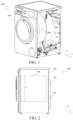
- FIG. 1 shows a laundry treatment apparatus 1000 according to an exemplary embodiment of the present invention, where some internal structures of the laundry treatment apparatus 1000 are shown.
- FIG. 2 is a side view of a laundry treatment apparatus 1000 according to an exemplary embodiment of the present invention.
- FIG. 3 is a cross-sectional view of a laundry treatment apparatus 1000 according to an exemplary embodiment of the present invention.
- FIG. 1, FIG. 2 , and FIG. 3 schematically show a coordinate system xyz of the laundry treatment apparatus 1000, where x represents a width direction of the laundry treatment apparatus 1000, y represents a height direction of the laundry treatment apparatus 1000, and z represents a depth direction in which the laundry treatment apparatus 1000 extends from the outside toward the inside.
- x represents a width direction of the laundry treatment apparatus 1000
- y represents a height direction of the laundry treatment apparatus 1000
- z represents a depth direction in which the laundry treatment apparatus 1000 extends from the outside toward the inside.
- the laundry treatment apparatus 1000 includes: a box 900, a laundry accommodating cavity 800 provided in the box 900, and a heat exchanger assembly 700 arranged in the box 900 and constructed in a module form.
- the laundry accommodating cavity 800 is particularly understood as, for example, an outer tub of a washer-dryer.
- the outer tub usually further includes a rotatable inner tub to directly accommodate laundry to be washed or to be dried.
- the laundry accommodating cavity 800 may be understood as a space configured to accommodate the laundry to be dried or a container including the space.
- the laundry treatment apparatus 1000 may be configured as a heat pump dryer or a heat pump washer-dryer.
- the laundry accommodating cavity 800 is provided with an air inlet 801 and an air outlet 802 for air suitable for drying laundry to enter and flow out
- the heat exchanger assembly 700 includes an air input end 701 and an air outlet end 702.
- the air input end 701 of the heat exchanger assembly 700 is in communication with the air outlet 802 of the laundry accommodating cavity 800
- the air outlet end 702 of the heat exchanger assembly 700 is in communication with the air inlet 801 of the laundry accommodating cavity 800, so that a flow path 700' suitable for air from the laundry accommodating cavity 800 to flow is formed between the air input end 701 and the air outlet end 702 of the heat exchanger assembly 700 (which may also refer to FIG. 7 described below).
- hot and humid air from the laundry accommodating cavity 800 flows from the air outlet 802 of the laundry accommodating cavity 800 into the air input end 701 of the heat exchanger assembly 700, flows through the flow path 700' and flows out of the air outlet end 702 of the heat exchanger assembly 700, and then flows into the laundry accommodating cavity 800 again through the air inlet 801 of the laundry accommodating cavity 800, to form air circulation.
- the laundry treatment apparatus 1000 further includes a fan 40 located between the air outlet end 702 and the air inlet 801.
- the fan 40 is configured to blow hot air discharged from the air outlet end 702 into the laundry accommodating cavity 800 through the air inlet 801, to form a circulating air path.
- the laundry treatment apparatus 1000 further includes a filter 50 located between the air outlet 802 and the air input end 701.
- the laundry treatment apparatus 1000 further includes a connecting pipe 60 (especially a corrugated hose) located between the air outlet 802 and the air input end 701.
- the filter 50 is arranged at an end of the connecting pipe 60 close to the laundry accommodating cavity 800.
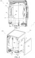
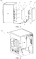
- FIG. 4 is an exploded view of a laundry treatment apparatus 1000 according to an exemplary embodiment of the present invention.
- FIG. 5 is an exploded view of a laundry treatment apparatus 1000 according to an exemplary embodiment of the present invention.
- FIG. 6 shows a laundry treatment apparatus 1000 according to an exemplary embodiment of the present invention, where some internal structures of a heat exchanger assembly 700 of the laundry treatment apparatus 1000 are shown.
- the heat exchanger assembly 700 of the laundry treatment apparatus 1000 includes a first heat exchanger 710 located on the flow path 700', where the first heat exchanger 710 is adapted to absorb heat of flowing air to condense the air; and the heat exchanger assembly 700 further includes a second heat exchanger 720 that is on the flow path 700' and that is located downstream of the first heat exchanger 710, where the second heat exchanger 720 is adapted to release heat for absorption by flowing air to heat the air.
- the first heat exchanger 710 is configured as an evaporator
- the second heat exchanger 720 is configured as a condenser.
- the heat exchanger assembly 700 of the laundry treatment apparatus 1000 is modularly constructed, and particularly, related parts may be integrally arranged, which especially saves a mounting space.
- the box 900 of the laundry treatment apparatus 1000 includes a back plate 910 on a side far away from a user, and the heat exchanger assembly 700 is arranged between the back plate 910 and the laundry accommodating cavity 800.
- the heat exchanger assembly 700 abuts against the back plate 910. It may be understood that, according to embodiments not shown in the accompanying drawings of the present invention, the heat exchanger assembly 700 may alternatively be arranged at another position in the box 900, for example, may be abuts against one side wall 920 of the box 900. However, the heat exchanger assembly 700 preferably abuts against the back plate 910. This is because, for the laundry treatment apparatus 1000, the box has a large space and is far away from the user, which may not be easily perceived by the user, and can improve use experience.
- the heat exchanger assembly 700 of the laundry treatment apparatus 1000 includes a flat housing 10 to at least wrap the first heat exchanger 710 and the second heat exchanger 720.
- the housing 10 of the heat exchanger assembly 700 is formed by connecting (especially sealingly connecting) a first housing member 11 facing the laundry accommodating cavity 800 and a second housing member 12 far away from the laundry accommodating cavity 800 with each other, and as shown in the figure, the first housing member 11 and the second housing member 12 are preferably in a same shape, to be connected with each other in a completely matched manner (especially connected in a sealed manner).
- the heat exchanger assembly 700 of the laundry treatment apparatus 1000 is mounted upright in the box 900 of the laundry treatment apparatus 1000.
- the heat exchanger assembly 700 is fastened to two opposite side walls 920 of the box 900 through a fixing apparatus 70.
- the fixing apparatus 70 is configured as three parallel reinforcing ribs, and fixes the housing 10 of the heat exchanger assembly 700 (especially the first housing member 11) to the two opposite side walls 920 of the box 900 through bolts.
- the laundry treatment apparatus 1000 further includes a compressor 600 and a restrictor 500 (particularly also located in the heat exchanger assembly 700, especially in the housing 10), and the compressor 600 and the restrictor 500 are connected to the evaporator that is used as the first heat exchanger 710 and the condenser that is used as the second heat exchanger 720 through a refrigerant pipeline to form a refrigerant circulation loop 1001.
- the refrigerant circulation loop 1001 may operate as follows: A gaseous coolant (for example, a gaseous refrigerant) is converted from low-pressure gas into high-pressure gas under the action of the compressor 600 and enters the condenser used as the second heat exchanger 720. In this case, the gas releases heat and is liquefied into a high-pressure liquid, and the high-pressure liquid enters the restrictor 500. Then the restrictor 500 depressurizes the high-pressure liquid to a low-pressure liquid, and the low-pressure liquid enters the evaporator that is used as the first heat exchanger 710. In this case, liquid absorbs heat and is evaporated into low-pressure gas, and the gas enters the compressor 600 again, so that a next round of cycle is performed.
- a gaseous coolant for example, a gaseous refrigerant
- FIG. 7 is a schematic diagram of a flow path formed inside a heat exchanger assembly 700 of a laundry treatment apparatus 1000 according to an exemplary embodiment of the present invention, where a direction of gravity G is also shown.
- FIG. 8 shows some structures of a heat exchanger assembly 700 of a laundry treatment apparatus 1000 according to an exemplary embodiment of the present invention.
- FIG. 9 shows some structures of a heat exchanger assembly 700 of a laundry treatment apparatus 1000 according to another exemplary embodiment of the present invention.
- the flow path 700' of the heat exchanger assembly 700 sequentially includes at least a first section 100, a second section 200, and a third section 300, where air from the laundry accommodating cavity 800 at least partially flows on the first section 100 and the third section 300 in a direction opposite to a direction of gravity G, and at least partially flows on the second section 200 in the direction of gravity G.
- the flow path 700' of the heat exchanger assembly 700 preferably further includes a first transition section 101 connecting the first section 100 and the second section 200 and a second transition section 102 connecting the second section 200 and the third section 300, where the first transition section 101 and/or the second transition section 102 are preferably configured as a smooth turning portion.
- such a curved transition forms a flow channel in a shape similar to an S shape, so that air flows more gently and more stably.
- the air input end 701 of the heat exchanger assembly 700 is as close as possible to an edge of the laundry accommodating cavity 800 (that is, as far as possible from a center of the laundry accommodating cavity 800).
- the air input end 701 may be located within a range of a fourth quadrant of the laundry accommodating cavity 800 with reference to the center of the laundry accommodating cavity 800. In this way, the air input end 701 is as low as possible while fully utilizing an available space, so that the heat exchanger assembly 700 has a flow path 700' as long as possible, thereby ensuring a sufficient heat exchange effect.
- the second heat exchanger 720 of the heat exchanger assembly 700 is located on the third section 300, and the air outlet end 702 is located at a tail end of the third section 300.
- the air input end 701 is located at a head end of the first section 100.
- FIG. 8 shows that the first heat exchanger 710 of the heat exchanger assembly 700 is located on the third section 300
- FIG. 9 shows that the first heat exchanger 710 of the heat exchanger assembly 700 is located on the second section 200.
- both the first heat exchanger 710 and the second heat exchanger 720 of the heat exchanger assembly 700 are located on the third section 300, the second section 200 is not necessarily designed to be too wide, which makes a layout of the heat exchanger assembly 700 more compact.
- both the first heat exchanger 710 and the second heat exchanger 720 of the heat exchanger assembly 700 can be designed to respectively occupy most flow channels of the second section 200 and the third section 300, to implement more sufficient heat exchange on air from the laundry accommodating cavity 800.
- the laundry treatment apparatus 1000 is configured to run a washing program and a drying program.
- the laundry accommodating cavity 800 contains washing water.
- a position of an upper end of the first section 100 in a height direction y is as high as possible and is at least higher than two thirds of a height H of the laundry accommodating cavity 800 (see refer to FIG. 2 ), that is, the position of the upper end of the first section 100 is higher than 2/3H, for example, at 3/4H.
- a position of the air outlet 802 of the laundry accommodating cavity 800 is arranged to be at least partially lower than a water inlet level of the washing program.
- the air outlet 802 of the laundry accommodating cavity 800 or the air input end 701 of the heat exchanger assembly 700 is designed to be as low as possible, which can further achieve an effect of lengthening an air flow path, and especially enable hot and humid air from the laundry accommodating cavity 800 to be more fully pre-condensed.
- the first section 100 and the second section 200 are separated through a waterproof rib 21 molded on the housing 10 (especially the first housing member 11) of the heat exchanger assembly 700.
- the laundry treatment apparatus 1000 includes a filter 50 arranged close to the air outlet 802 of the laundry accommodating cavity 800 or the air input end 701 of the heat exchanger assembly 700.
- the filter 50 is arranged between the air outlet 802 of the laundry accommodating cavity 800 and the air input end 701 of the heat exchanger assembly 700.
- the heat exchanger assembly 700 further includes at least one boundary wall 703 bounding the flow path 700', and the boundary wall 703 is configured to be adapted to pre-condense air on the flow path 700'.
- Pre-condense may particularly mean that, in addition to a main condensation process on the flow path 700' occurred when air flows through the first heat exchanger 710, the hot and humid air from the laundry accommodating cavity 800 can also release heat to some extent when flowing through the boundary wall 703 and is pre-condensed.
- the boundary wall 703 may be molded on the first housing member 11 and the second housing member 12. Especially, the boundary wall 703 is sealed relative to the outside, to prevent air on the flow path 700' from escaping.
- the heat exchanger assembly 700 further includes at least one flow guide rib 704 located on the flow path 700', and the flow guide rib 704 is particularly, as shown in the figure, located within a range of the first transition section 101 and/or the second transition section 102.
- the flow guide rib 704 may be molded only on the first housing member 11, to simplify a manufacturing process.
- FIG. 8 schematically shows, by using a dash-dotted line, a vertical center plane E equally dividing the laundry accommodating cavity 800 in a horizontal direction. It may also be understood that, the vertical center plane E is perpendicular to a horizontal plane and/or extends along a diameter of the laundry accommodating cavity 800. As shown in the figure, the compressor 600 is mounted at a bottom of the box 900 and deviates from the vertical center plane E of the laundry accommodating cavity 800 in the direction of gravity G.
- FIG. 10 is a partially enlarged view at A in FIG. 9 .
- the heat exchanger assembly 700 is further provided with a condensate discharge port 30 that is in a region of the second transition section 102 (especially at a lowest point of the flow path 700' in a height direction y of the laundry treatment apparatus 1000).
- a condensate discharge port 30 that is in a region of the second transition section 102 (especially at a lowest point of the flow path 700' in a height direction y of the laundry treatment apparatus 1000).
- condensate can be discharged through the condensate discharge port 30 and take away fluff or other contaminants that may be present.
- the second heat exchanger 720 that is used as the evaporator is more preferably arranged in the third section 300, that is, the arrangement manner shown in FIG. 8 .
- the heat exchanger assembly 700 further includes a dislocation guide rib 31 in a region of the condensate discharge port 30, where the dislocation guide rib 31 is configured to be adapted to guide a discharge direction of condensate in the condensate discharge port 30 to be opposite to a flow direction of air in the condensate discharge port.
- the dislocation guide rib 31 obliquely extends downward from a downstream side of the air flow direction, and an inclination direction is opposite to the air flow direction.
- the air flow direction is from right to left, while the dislocation guide rib 31 is obliquely arranged downward from left to right.
- the arrangement manner is particularly conducive to discharge of liquids (or mixed solids) along the flow guide rib that inclines downward from left to right while prevent air from being discharged through the condensate discharge port 30.
- the laundry treatment apparatus 1000 further includes a pump 80 that is connected to the laundry accommodating cavity 800 and is configured to drain liquids when a washing program is run, the housing 10 of the heat exchanger assembly 700 is provided with a liquid drainage connector 32 at a lowest point in the height direction y, and the liquid drainage connector 32 is connected to the pump (80) through a pipe 90.
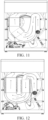
- FIG. 11 shows some structures of the heat exchanger assembly of the laundry treatment apparatus based on FIG. 8
- FIG. 12 shows some structures of the heat exchanger assembly of the laundry treatment apparatus based on FIG. 9 , where arrows schematically show flow directions of air in the heat exchanger assembly 700 in FIG. 11 and FIG. 12 .
Landscapes
- Engineering & Computer Science (AREA)
- Textile Engineering (AREA)
- Detail Structures Of Washing Machines And Dryers (AREA)
Abstract
The present invention relates to the field of laundry treatment apparatus technologies, and specifically, to a laundry treatment apparatus. The laundry treatment apparatus (1000) includes: a box (900); a laundry accommodating cavity (800) provided in the box (900), wherein the laundry accommodating cavity (800) is provided with an air inlet (801) and an air outlet (802) for air for drying laundry to enter and flow out; a heat exchanger assembly (700) arranged in the box (900) and constructed in a module form, wherein the heat exchanger assembly (700) includes: an air input end (701) in communication with the air outlet (802) of the laundry accommodating cavity (800) and an air outlet end (702) in communication with the air inlet (801) of the laundry accommodating cavity (800), wherein a flow path (700') for air to flow is formed between the air input end (701) and the air outlet end (702); a first heat exchanger (710) located on the flow path (700'), adapted to absorb heat of flowing air to condense the air; and a second heat exchanger (720) that is on the flow path (700') and that is located downstream of the first heat exchanger (710), adapted to release heat for absorption by flowing air to heat the air. According to the present invention, the heat exchanger assembly is centrally arranged inside the box of the laundry treatment apparatus, which is particularly conducive to mounting and disassembly of related parts, and also facilitates maintenance personnel to directly replace an entire module.
Description
- The present invention relates to the field of laundry treatment apparatus technologies, and specifically, to a laundry treatment apparatus.
- Currently, with the development of economy and improvement of people's living standards, laundry treatment apparatuses (for example, a laundry dryer, a washer-dryer, and the like) have been widely used. To achieve a drying function, the laundry treatment apparatus should be equipped with a heat exchanger and a plurality of related parts. However, the heat exchanger and the related parts are usually scattered inside a box of the laundry treatment apparatus. Such an arrangement manner is particularly not conducive to overhaul and maintenance of related functions of the laundry treatment apparatus, and is also not conducive to mounting and disassembly of the related parts.
- Based on the above, there is still a real need for continuous improvement in a structure of the laundry treatment apparatus.
- In view of this, an objective of embodiments of the present invention is to provide an improved laundry treatment apparatus, to at least overcome one of the foregoing disadvantages and/or another possible disadvantage not mentioned in this specification.
- According to the embodiments of the present invention, a laundry treatment apparatus is provided. The laundry treatment apparatus includes: a box; a laundry accommodating cavity provided in the box, where the laundry accommodating cavity is provided with an air inlet and an air outlet for air suitable for drying laundry to enter and flow out; a heat exchanger assembly arranged in the box and constructed in a module form, where the heat exchanger assembly includes at least: an air input end in communication with the air outlet of the laundry accommodating cavity and an air outlet end in communication with the air inlet of the laundry accommodating cavity, where a flow path suitable for air from the laundry accommodating cavity to flow is formed between the air input end and the air outlet end; a first heat exchanger located on the flow path, where the first heat exchanger is adapted to absorb heat of flowing air to condense the air; and a second heat exchanger that is on the flow path and that is located downstream of the first heat exchanger, where the second heat exchanger is adapted to release heat for absorption by flowing air to heat the air. Therefore, the air inlet and the air outlet are in communication with the air inlet end and the air outlet end in terms of air flow, so that it is ensured that the laundry treatment apparatus may implement a drying circulation loop in which air suitable for drying laundry enters and flows out, and enters the laundry accommodating cavity again. In addition, the heat exchanger assembly including a plurality of heat exchangers sequentially on the flow path is constructed in a module form, so that it is ensured that the heat exchanger assembly with a heat exchange function is centrally arranged inside the box of the laundry treatment apparatus, which is particularly conducive to mounting and disassembly of related parts, and also facilitates maintenance personnel to directly replace an entire module.
- According to an optional embodiment of the present invention, the box includes a back plate on a side far away from a user, and the heat exchanger assembly is arranged between the back plate and the laundry accommodating cavity. In this way, a mounting position of the heat exchanger assembly particularly effectively uses an available space of the box of the laundry treatment apparatus between the back plate and the laundry accommodating cavity, so that there is no need to deliberately choose a heat exchanger that is too small to save a mounting space, which also improves drying efficiency.
- According to an optional embodiment of the present invention, the heat exchanger assembly includes a flat housing to at least wrap the first heat exchanger and the second heat exchanger. In this way, the heat exchanger assembly including the flat housing can particularly be arranged inside the box of the laundry treatment apparatus in a space-saving manner, and parts of the heat exchanger assembly may not be too scattered.
- According to an optional embodiment of the present invention, the heat exchanger assembly is mounted upright in the box of the laundry treatment apparatus. In this way, the mounting space occupied by the heat exchanger assembly inside the box of the laundry treatment apparatus is further saved.
- According to an optional embodiment of the present invention, the heat exchanger assembly abuts against the back plate. In this way, for example, maintenance personnel may perform overhaul on the heat exchanger assembly by simply disassembling the back plate, which particularly simplifies a procedure of an overhaul operation, and makes maintenance particularly easy.
- According to an optional embodiment of the present invention, the housing of the heat exchanger assembly is formed by connecting (especially sealingly connecting) a first housing member facing the laundry accommodating cavity and a second housing member far away from the laundry accommodating cavity with each other, and the first housing member and the second housing member are preferably in a same shape. In this way, the two housing members are assembled into the housing, which is easy to manufacture. In addition, for example, the first or second heat exchanger in the housing member may be maintained in an overhaul process by separating the two housing members.
- According to an optional embodiment of the present invention, the heat exchanger assembly is fastened to two opposite side walls of the box through a fixing apparatus. In this way, the heat exchanger assembly can be directly connected to the box instead of being connected to, for example, an outer tub of the laundry treatment apparatus. Particularly, the heat exchanger assembly may still not be affected even if, for example, the outer tub shakes during operation of the laundry treatment apparatus.
- According to an optional embodiment of the present invention, in an air flow direction, the flow path of the heat exchanger assembly sequentially includes at least a first section, a second section, and a third section, where air from the laundry accommodating cavity at least partially flows on the first section and the third section in a direction opposite to a direction of gravity, and at least partially flows on the second section in the direction of gravity. In this way, a limited space inside the box of the laundry treatment apparatus is fully used, which enables air from the laundry accommodating cavity to have a flow path as long as possible inside the heat exchanger assembly, and ensures that condensate can be separated from air under the action of gravity.
- According to an optional embodiment of the present invention, the first heat exchanger is located on the second section or the third section. In this way, it is ensured that the first heat exchanger may not be located on the first section close to the air outlet of the laundry accommodating cavity, which particularly prevents substances (such as washing water and/or foam) that may be overflown when the laundry treatment apparatus runs the washing program from entering the first section and affecting a function of the first heat exchanger.
- According to an optional embodiment of the present invention, the second heat exchanger is located on the third section, and the air outlet end is located at a tail end of the third section. In this way, such a layout ensures that air flowing inside the heat exchanger assembly leaves the heat exchanger assembly through the air outlet end shortly after absorbing heat from the second heat exchanger, which particularly prevents unnecessary heat losses.
- According to an optional embodiment of the present invention, the flow path of the heat exchanger assembly further includes a first transition section connecting the first section and the second section and a second transition section connecting the second section and the third section, where the first transition section and/or the second transition section are configured as a smooth turning portion. In this way, air from the laundry accommodating cavity makes a smooth transition when flowing between the first section and the second section and/or between the second section and the third section, which avoids unnecessary energy loss.
- According to an optional embodiment of the present invention, the laundry treatment apparatus is configured to run a washing program and a drying program, and the laundry accommodating cavity contains washing water when the washing program is run, where a position of an upper end of the first section in a height direction is at least higher than two-thirds of a height of the laundry accommodating cavity. In this way, particularly, gravity is used to prevent substances (such as washing water and/or foam) that may be overflown when the laundry treatment apparatus runs the washing program from crossing the upper end of the first section, entering a subsequent device, and affecting a function of the device.
- According to an optional embodiment of the present invention, the first section and the second section are separated through a waterproof rib molded on the housing, especially the first housing member of the heat exchanger assembly. In this way, the waterproof rib is simply manufactured on the housing (especially the first housing member), to ensure that even substances (such as washing water and/or foam) that enter the first section from the laundry accommodating cavity can no longer enter the second section and affect the function of the subsequent device.
- According to an optional embodiment of the present invention, a position of the air outlet of the laundry accommodating cavity is arranged to be at least partially lower than a water inlet level of the washing program. In this way, fluff or other contaminants accumulated near the air outlet of the laundry accommodating cavity can be repeatedly flushed by using washing water when the laundry treatment apparatus runs the washing program, and fluff or other contaminants on the first section may even be flushed, thereby achieving a cleaning effect near the air outlet of the laundry accommodating cavity or even the air input end of the heat exchanger assembly, and avoiding blockage.
- According to an optional embodiment of the present invention, a filter is arranged close to the air outlet of the laundry accommodating cavity or the air input end of the heat exchanger assembly. In this way, particularly, when the laundry treatment apparatus runs the washing program, the filter can be repeatedly flushed to take away, for example, fluff or other contaminants accumulated on the filter, which is equivalent to achieving a self-cleaning effect of the filter without deliberately arranging an additional waterway connecting member. This particularly saves a space, reduces power consumption, and improves efficiency.
- According to an optional embodiment of the present invention, the heat exchanger assembly is further provided with a condensate discharge port that is in a region of the second transition section and especially at a lowest point of the flow path in a height direction of the laundry treatment apparatus. In this way, even washing water or foam that crosses the first transition section and enters the second transition section can still be discharged through the condensate discharge port.
- According to an optional embodiment of the present invention, the heat exchanger assembly further includes a dislocation guide rib in a region of the condensate discharge port, where the dislocation guide rib is configured to be adapted to guide a discharge direction of condensate in the condensate discharge port to be opposite to a flow direction of air in the condensate discharge port. In this way, it is ensured that condensate is discharged through the condensate discharge port in a direction opposite to a flow direction of air under the action of gravity, and the air continues to flow forward without being affected, so that a loss of air is reduced, and the air flows more smoothly inside the heat exchanger assembly.
- According to an optional embodiment of the present invention, the laundry treatment apparatus includes a pump that is connected to the laundry accommodating cavity and is configured to drain liquids when a washing program is run, the housing of the heat exchanger assembly is provided with a liquid drainage connector at a lowest point in the height direction, and the liquid drainage connector is connected to the pump through a pipe. In this way, the pump can be used to implement a liquid drainage function, for example, when the washing program is run, and drain condensate in a drying process.
- According to an optional embodiment of the present invention, the dislocation guide rib obliquely extends downward from a downstream side of the air flow direction, and an inclination direction is opposite to the air flow direction. In this way, it is ensured that the condensate is discharged, under the action of gravity, downward from the downstream side of the air flow direction and in a direction opposite to the air flow direction, to be separated from air.
- According to an optional embodiment of the present invention, the heat exchanger assembly further includes at least one boundary wall bounding the flow path, and the boundary wall is configured to be adapted to pre-condense air on the flow path. In this way, based on a heat transfer effect of the boundary wall as a solid substance, condensation may be achieved to some extent when air flows through the boundary wall, thereby further improving condensation efficiency.
- According to an optional embodiment of the present invention, the heat exchanger assembly further includes at least one flow guide rib located on the flow path, and the flow guide rib is particularly located within a range of the first transition section and/or the second transition section. In this way, air from the laundry accommodating cavity is advantageously guided to uniformly flow through the heat exchanger assembly, to achieve a more sufficient heat exchange effect.
- According to an optional embodiment of the present invention, the first heat exchanger is configured as an evaporator, and the second heat exchanger is configured as a condenser. In this way, the heat exchange effect required by the heat exchanger assembly is achieved through the evaporator and the condenser.
- According to an optional embodiment of the present invention, the laundry treatment apparatus further includes a compressor and a restrictor (particularly located in the heat exchanger assembly, especially in the housing), and the compressor and the restrictor are connected to the evaporator that is used as the first heat exchanger and the condenser that is used as the second heat exchanger through a refrigerant pipeline to form a refrigerant circulation loop. In this way, the restrictor forming the refrigerant circulation loop is also included in the heat exchanger assembly, especially in the housing of the heat exchanger assembly, so that a modular construction manner of the heat exchanger assembly is more complete, and parts in the box of the laundry treatment apparatus are arranged to be more compact.
- According to an optional embodiment of the present invention, the laundry treatment apparatus is configured as a heat pump dryer or a heat pump washer-dryer. In this way, the modular construction manner of the heat exchanger assembly can be implemented for the heat pump dryer or the heat pump washer-dryer, which is particularly beneficial to implementation of space-saving arrangement internal components (especially a heat pump assembly) of the heat pump dryer or the heat pump washer-dryer.
- According to an optional embodiment of the present invention, the compressor is mounted at a bottom of the box and deviates from a vertical center plane of the laundry accommodating cavity in the direction of gravity. In this way, it is ensured that the compressor, which is usually heavier and occupies a larger space, is arranged at a position with a sufficient mounting space inside the box of the laundry treatment apparatus.
- The present invention is described in more detail with reference to the accompanying drawings, which can better understand principles, features, and advantages of the present invention. The accompanying drawings include:
-
FIG. 1 shows a laundry treatment apparatus according to an exemplary embodiment of the present invention, where some internal structures of the laundry treatment apparatus are shown; -
FIG. 2 is a side view of a laundry treatment apparatus according to an exemplary embodiment of the present invention; -
FIG. 3 is a cross-sectional view of a laundry treatment apparatus according to an exemplary embodiment of the present invention; -
FIG. 4 is an exploded view of a laundry treatment apparatus according to an exemplary embodiment of the present invention; -
FIG. 5 is an exploded view of a laundry treatment apparatus according to an exemplary embodiment of the present invention; -
FIG. 6 shows a laundry treatment apparatus according to an exemplary embodiment of the present invention, where some internal structures of a heat exchanger assembly of the laundry treatment apparatus are shown; -
FIG. 7 is a schematic diagram of a flow path formed inside a heat exchanger assembly of a laundry treatment apparatus according to an exemplary embodiment of the present invention; -
FIG. 8 shows some structures of a heat exchanger assembly of a laundry treatment apparatus according to an exemplary embodiment of the present invention; -
FIG. 9 shows some structures of a heat exchanger assembly of a laundry treatment apparatus according to another exemplary embodiment of the present invention; -
FIG. 10 is a partially enlarged view at A inFIG. 9 ; -
FIG. 11 shows some structures of the heat exchanger assembly of the laundry treatment apparatus based onFIG. 8 , where arrows schematically illustrate flow directions of air in the heat exchanger assembly; and -
FIG. 12 shows some structures of the heat exchanger assembly of the laundry treatment apparatus based onFIG. 9 , where arrows schematically illustrate flow directions of air in the heat exchanger assembly. - To make technical problems to be resolved in the present invention, technical solutions, and beneficial effects clearer and more comprehensible, the following further describes the present invention in detail with reference to the accompanying drawings and a plurality of exemplary embodiments. It should be understood that the specific embodiments herein are merely provided for describing the present invention and not intended to limit the protection scope of the present invention. In addition, various embodiments may be described by sharing a same figure or a plurality of figures, but all features appearing in the same figure cannot be interpreted as features that are necessarily included in one embodiment.
- Before description, it is to be pointed out that, for the sake of convenience, orientation terms or direction terms may be used in this specification for description, the orientation terms or direction terms are relative to a conventional use state of a laundry treatment apparatus. A person skilled in the art may be clear from the description of the present invention without causing any confusion. In this case, the orientation terms and the direction terms should not be simply construed as indicating an orientation or direction in any state. In other words, in the descriptions of the present invention, orientation or position relationships indicated by the terms such as "above", "below", "front", "rear", "left", "right", "vertical", "horizontal", "top", "bottom", "inner", "outer", "longitudinal", "transverse", "high", "right", and "back" are based on orientation or position relationships shown in the accompanying drawings, and are used only for ease and brevity of illustration and description of the present invention, rather than indicating or implying that the mentioned apparatus or component must have a particular orientation or must be constructed and operated in a particular orientation. Therefore, such terms should not be construed as limiting of the present invention.
- In addition, in the descriptions of the present invention, "A and/or B" represents all possible combinations of A and B, for example, only A exists, only B exists, and both A and B exist. The terms "first" and "second" are used for descriptive purposes only and are not to be construed as indicating or implying relative importance or implicitly indicating the number of technical features indicated. Therefore, features defining "first" and "second" may explicitly or implicitly include one or more such features.
- First, for ease of understanding, the descriptions made in BACKGROUND of the present invention may be backtracked or recalled. One of the objectives of the present invention is to provide an improved laundry treatment apparatus, including: a box; a laundry accommodating cavity provided in the box, where the laundry accommodating cavity is provided with an air inlet and an air outlet for air suitable for drying laundry to enter and flow out; a heat exchanger assembly arranged in the box and constructed in a module form, where the heat exchanger assembly includes at least: an air input end in communication with the air outlet of the laundry accommodating cavity and an air outlet end in communication with the air inlet of the laundry accommodating cavity, where a flow path suitable for air from the laundry accommodating cavity to flow is formed between the air input end and the air outlet end; a first heat exchanger located on the flow path, where the first heat exchanger is adapted to absorb heat of flowing air to condense the air; and a second heat exchanger that is on the flow path and that is located downstream of the first heat exchanger, where the second heat exchanger is adapted to release heat for absorption by flowing air to heat the air. Therefore, the air inlet and the air outlet are in communication with the air inlet end and the air outlet end in terms of air flow, so that it is ensured that the laundry treatment apparatus may implement a drying circulation loop in which air suitable for drying laundry enters and flows out, and enters the laundry accommodating cavity again. In addition, the heat exchanger assembly including a plurality of heat exchangers sequentially on the flow path is constructed in a module form, so that it is ensured that the heat exchanger assembly with a heat exchange function is centrally arranged inside the box of the laundry treatment apparatus, which is particularly conducive to mounting and disassembly of related parts, and also facilitates maintenance personnel to directly replace an entire module.
- The following describes the exemplary embodiments of the present invention with reference to the accompanying drawings.
-
FIG. 1 shows alaundry treatment apparatus 1000 according to an exemplary embodiment of the present invention, where some internal structures of thelaundry treatment apparatus 1000 are shown.FIG. 2 is a side view of alaundry treatment apparatus 1000 according to an exemplary embodiment of the present invention.FIG. 3 is a cross-sectional view of alaundry treatment apparatus 1000 according to an exemplary embodiment of the present invention. -
FIG. 1, FIG. 2 , andFIG. 3 schematically show a coordinate system xyz of thelaundry treatment apparatus 1000, where x represents a width direction of thelaundry treatment apparatus 1000, y represents a height direction of thelaundry treatment apparatus 1000, and z represents a depth direction in which thelaundry treatment apparatus 1000 extends from the outside toward the inside. For clarity, illustration and description are made in some accompanying drawings basically with reference to the coordinate system xyz. - As shown in
FIG. 1, FIG. 2 , andFIG. 3 , thelaundry treatment apparatus 1000 according to an exemplary embodiment of the present invention includes: abox 900, a laundryaccommodating cavity 800 provided in thebox 900, and aheat exchanger assembly 700 arranged in thebox 900 and constructed in a module form. In this case, for example, for alaundry treatment apparatus 1000 in a drum type, the laundryaccommodating cavity 800 is particularly understood as, for example, an outer tub of a washer-dryer. The outer tub usually further includes a rotatable inner tub to directly accommodate laundry to be washed or to be dried. For anotherlaundry treatment apparatus 1000 in a non-drum type, the laundryaccommodating cavity 800 may be understood as a space configured to accommodate the laundry to be dried or a container including the space. According to an exemplary embodiment of the present invention, thelaundry treatment apparatus 1000 may be configured as a heat pump dryer or a heat pump washer-dryer. - As shown in
FIG. 3 , the laundryaccommodating cavity 800 is provided with anair inlet 801 and anair outlet 802 for air suitable for drying laundry to enter and flow out, and theheat exchanger assembly 700 includes anair input end 701 and anair outlet end 702. Theair input end 701 of theheat exchanger assembly 700 is in communication with theair outlet 802 of the laundryaccommodating cavity 800, and theair outlet end 702 of theheat exchanger assembly 700 is in communication with theair inlet 801 of the laundryaccommodating cavity 800, so that a flow path 700' suitable for air from the laundryaccommodating cavity 800 to flow is formed between theair input end 701 and theair outlet end 702 of the heat exchanger assembly 700 (which may also refer toFIG. 7 described below). For example, when thelaundry treatment apparatus 1000 runs a drying program, hot and humid air from the laundryaccommodating cavity 800 flows from theair outlet 802 of the laundryaccommodating cavity 800 into theair input end 701 of theheat exchanger assembly 700, flows through the flow path 700' and flows out of theair outlet end 702 of theheat exchanger assembly 700, and then flows into the laundryaccommodating cavity 800 again through theair inlet 801 of the laundryaccommodating cavity 800, to form air circulation. - As shown in
FIG. 3 , thelaundry treatment apparatus 1000 further includes afan 40 located between theair outlet end 702 and theair inlet 801. Thefan 40 is configured to blow hot air discharged from theair outlet end 702 into the laundryaccommodating cavity 800 through theair inlet 801, to form a circulating air path. Optionally, thelaundry treatment apparatus 1000 further includes afilter 50 located between theair outlet 802 and theair input end 701. Particularly, thelaundry treatment apparatus 1000 further includes a connecting pipe 60 (especially a corrugated hose) located between theair outlet 802 and theair input end 701. Preferably, thefilter 50 is arranged at an end of the connectingpipe 60 close to the laundryaccommodating cavity 800. -
FIG. 4 is an exploded view of alaundry treatment apparatus 1000 according to an exemplary embodiment of the present invention.FIG. 5 is an exploded view of alaundry treatment apparatus 1000 according to an exemplary embodiment of the present invention.FIG. 6 shows alaundry treatment apparatus 1000 according to an exemplary embodiment of the present invention, where some internal structures of aheat exchanger assembly 700 of thelaundry treatment apparatus 1000 are shown. - As shown in
FIG. 5 and FIG. 6 , theheat exchanger assembly 700 of thelaundry treatment apparatus 1000 includes afirst heat exchanger 710 located on the flow path 700', where thefirst heat exchanger 710 is adapted to absorb heat of flowing air to condense the air; and theheat exchanger assembly 700 further includes asecond heat exchanger 720 that is on the flow path 700' and that is located downstream of thefirst heat exchanger 710, where thesecond heat exchanger 720 is adapted to release heat for absorption by flowing air to heat the air. For example, thefirst heat exchanger 710 is configured as an evaporator, and thesecond heat exchanger 720 is configured as a condenser. As schematically shown inFIG. 4 ,FIG. 5, and FIG. 6 , theheat exchanger assembly 700 of thelaundry treatment apparatus 1000 is modularly constructed, and particularly, related parts may be integrally arranged, which especially saves a mounting space. - As shown in
FIG. 4 andFIG. 5 , thebox 900 of thelaundry treatment apparatus 1000 includes aback plate 910 on a side far away from a user, and theheat exchanger assembly 700 is arranged between theback plate 910 and the laundryaccommodating cavity 800. - Particularly, the
heat exchanger assembly 700 abuts against theback plate 910. It may be understood that, according to embodiments not shown in the accompanying drawings of the present invention, theheat exchanger assembly 700 may alternatively be arranged at another position in thebox 900, for example, may be abuts against oneside wall 920 of thebox 900. However, theheat exchanger assembly 700 preferably abuts against theback plate 910. This is because, for thelaundry treatment apparatus 1000, the box has a large space and is far away from the user, which may not be easily perceived by the user, and can improve use experience. - As shown in
FIG. 4 andFIG. 5 , theheat exchanger assembly 700 of thelaundry treatment apparatus 1000 includes aflat housing 10 to at least wrap thefirst heat exchanger 710 and thesecond heat exchanger 720. Particularly, as shown inFIG. 5 , thehousing 10 of theheat exchanger assembly 700 is formed by connecting (especially sealingly connecting) afirst housing member 11 facing the laundryaccommodating cavity 800 and asecond housing member 12 far away from the laundryaccommodating cavity 800 with each other, and as shown in the figure, thefirst housing member 11 and thesecond housing member 12 are preferably in a same shape, to be connected with each other in a completely matched manner (especially connected in a sealed manner). - As shown in
FIG. 4 andFIG. 5 , theheat exchanger assembly 700 of thelaundry treatment apparatus 1000 is mounted upright in thebox 900 of thelaundry treatment apparatus 1000. Particularly, as shown inFIG. 5 in combination withFIG. 1 , theheat exchanger assembly 700 is fastened to twoopposite side walls 920 of thebox 900 through a fixingapparatus 70. As exemplarily shown in the figure, the fixingapparatus 70 is configured as three parallel reinforcing ribs, and fixes thehousing 10 of the heat exchanger assembly 700 (especially the first housing member 11) to the twoopposite side walls 920 of thebox 900 through bolts. - As shown in
FIG. 5 , thelaundry treatment apparatus 1000 further includes acompressor 600 and a restrictor 500 (particularly also located in theheat exchanger assembly 700, especially in the housing 10), and thecompressor 600 and therestrictor 500 are connected to the evaporator that is used as thefirst heat exchanger 710 and the condenser that is used as thesecond heat exchanger 720 through a refrigerant pipeline to form arefrigerant circulation loop 1001. For example, as an inner circulation loop of the heat pump dryer or the heat pump washer-dryer, therefrigerant circulation loop 1001 may operate as follows: A gaseous coolant (for example, a gaseous refrigerant) is converted from low-pressure gas into high-pressure gas under the action of thecompressor 600 and enters the condenser used as thesecond heat exchanger 720. In this case, the gas releases heat and is liquefied into a high-pressure liquid, and the high-pressure liquid enters therestrictor 500. Then the restrictor 500 depressurizes the high-pressure liquid to a low-pressure liquid, and the low-pressure liquid enters the evaporator that is used as thefirst heat exchanger 710. In this case, liquid absorbs heat and is evaporated into low-pressure gas, and the gas enters thecompressor 600 again, so that a next round of cycle is performed. -
FIG. 7 is a schematic diagram of a flow path formed inside aheat exchanger assembly 700 of alaundry treatment apparatus 1000 according to an exemplary embodiment of the present invention, where a direction of gravity G is also shown.FIG. 8 shows some structures of aheat exchanger assembly 700 of alaundry treatment apparatus 1000 according to an exemplary embodiment of the present invention.FIG. 9 shows some structures of aheat exchanger assembly 700 of alaundry treatment apparatus 1000 according to another exemplary embodiment of the present invention. - As shown in
FIG. 7 , in an air flow direction, the flow path 700' of theheat exchanger assembly 700 sequentially includes at least afirst section 100, asecond section 200, and athird section 300, where air from the laundryaccommodating cavity 800 at least partially flows on thefirst section 100 and thethird section 300 in a direction opposite to a direction of gravity G, and at least partially flows on thesecond section 200 in the direction of gravity G. In this case, the flow path 700' of theheat exchanger assembly 700 preferably further includes afirst transition section 101 connecting thefirst section 100 and thesecond section 200 and asecond transition section 102 connecting thesecond section 200 and thethird section 300, where thefirst transition section 101 and/or thesecond transition section 102 are preferably configured as a smooth turning portion. As shown in the figure, such a curved transition forms a flow channel in a shape similar to an S shape, so that air flows more gently and more stably. - As shown in
FIG. 8 andFIG. 9 in combination withFIG. 6 , theair input end 701 of theheat exchanger assembly 700 is as close as possible to an edge of the laundry accommodating cavity 800 (that is, as far as possible from a center of the laundry accommodating cavity 800). For example, theair input end 701 may be located within a range of a fourth quadrant of the laundryaccommodating cavity 800 with reference to the center of the laundryaccommodating cavity 800. In this way, theair input end 701 is as low as possible while fully utilizing an available space, so that theheat exchanger assembly 700 has a flow path 700' as long as possible, thereby ensuring a sufficient heat exchange effect. - As shown in
FIG. 8 andFIG. 9 in combination withFIG. 7 , thesecond heat exchanger 720 of theheat exchanger assembly 700 is located on thethird section 300, and theair outlet end 702 is located at a tail end of thethird section 300. Correspondingly, theair input end 701 is located at a head end of thefirst section 100. For example,FIG. 8 shows that thefirst heat exchanger 710 of theheat exchanger assembly 700 is located on thethird section 300, whileFIG. 9 shows that thefirst heat exchanger 710 of theheat exchanger assembly 700 is located on thesecond section 200. - As can be seen from comparison between
FIG. 8 andFIG. 9 , in an arrangement manner inFIG. 8 , since both thefirst heat exchanger 710 and thesecond heat exchanger 720 of theheat exchanger assembly 700 are located on thethird section 300, thesecond section 200 is not necessarily designed to be too wide, which makes a layout of theheat exchanger assembly 700 more compact. However, alternatively, in an arrangement manner inFIG. 9 , both thefirst heat exchanger 710 and thesecond heat exchanger 720 of theheat exchanger assembly 700 can be designed to respectively occupy most flow channels of thesecond section 200 and thethird section 300, to implement more sufficient heat exchange on air from the laundryaccommodating cavity 800. - According to an exemplary embodiment of the present invention, the
laundry treatment apparatus 1000 is configured to run a washing program and a drying program. When the washing program is run, the laundryaccommodating cavity 800 contains washing water. As shown inFIG. 7 and FIG. 8 , a position of an upper end of thefirst section 100 in a height direction y is as high as possible and is at least higher than two thirds of a height H of the laundry accommodating cavity 800 (see refer toFIG. 2 ), that is, the position of the upper end of thefirst section 100 is higher than 2/3H, for example, at 3/4H. Profitably, a position of theair outlet 802 of the laundryaccommodating cavity 800 is arranged to be at least partially lower than a water inlet level of the washing program. Theair outlet 802 of the laundryaccommodating cavity 800 or theair input end 701 of theheat exchanger assembly 700 is designed to be as low as possible, which can further achieve an effect of lengthening an air flow path, and especially enable hot and humid air from the laundryaccommodating cavity 800 to be more fully pre-condensed. - As shown in
FIG. 8 in combination withFIG. 7 , thefirst section 100 and thesecond section 200 are separated through awaterproof rib 21 molded on the housing 10 (especially the first housing member 11) of theheat exchanger assembly 700. - As shown in
FIG. 9 in combination withFIG. 3 , thelaundry treatment apparatus 1000 includes afilter 50 arranged close to theair outlet 802 of the laundryaccommodating cavity 800 or theair input end 701 of theheat exchanger assembly 700. Optionally, thefilter 50 is arranged between theair outlet 802 of the laundryaccommodating cavity 800 and theair input end 701 of theheat exchanger assembly 700. - As shown in
FIG. 8 andFIG. 9 , theheat exchanger assembly 700 further includes at least oneboundary wall 703 bounding the flow path 700', and theboundary wall 703 is configured to be adapted to pre-condense air on the flow path 700'. "Pre-condense" may particularly mean that, in addition to a main condensation process on the flow path 700' occurred when air flows through thefirst heat exchanger 710, the hot and humid air from the laundryaccommodating cavity 800 can also release heat to some extent when flowing through theboundary wall 703 and is pre-condensed. Particularly, theboundary wall 703 may be molded on thefirst housing member 11 and thesecond housing member 12. Especially, theboundary wall 703 is sealed relative to the outside, to prevent air on the flow path 700' from escaping. - As shown in
FIG. 8 andFIG. 9 , theheat exchanger assembly 700 further includes at least oneflow guide rib 704 located on the flow path 700', and theflow guide rib 704 is particularly, as shown in the figure, located within a range of thefirst transition section 101 and/or thesecond transition section 102. Particularly, theflow guide rib 704 may be molded only on thefirst housing member 11, to simplify a manufacturing process. -
FIG. 8 schematically shows, by using a dash-dotted line, a vertical center plane E equally dividing the laundryaccommodating cavity 800 in a horizontal direction. It may also be understood that, the vertical center plane E is perpendicular to a horizontal plane and/or extends along a diameter of the laundryaccommodating cavity 800. As shown in the figure, thecompressor 600 is mounted at a bottom of thebox 900 and deviates from the vertical center plane E of the laundryaccommodating cavity 800 in the direction of gravity G. -
FIG. 10 is a partially enlarged view at A inFIG. 9 . - As shown in
FIG. 10 in combination withFIG. 9 andFIG. 7 , theheat exchanger assembly 700 is further provided with acondensate discharge port 30 that is in a region of the second transition section 102 (especially at a lowest point of the flow path 700' in a height direction y of the laundry treatment apparatus 1000). In this way, condensate can be discharged through thecondensate discharge port 30 and take away fluff or other contaminants that may be present. In addition, even if washing water or foam accidentally crosses thefirst transition section 101 and enters thesecond transition section 102, the washing water or foam can be discharged through thecondensate discharge port 30. Based on this, thesecond heat exchanger 720 that is used as the evaporator is more preferably arranged in thethird section 300, that is, the arrangement manner shown inFIG. 8 . - As further shown in
FIG. 10 , theheat exchanger assembly 700 further includes adislocation guide rib 31 in a region of thecondensate discharge port 30, where thedislocation guide rib 31 is configured to be adapted to guide a discharge direction of condensate in thecondensate discharge port 30 to be opposite to a flow direction of air in the condensate discharge port. Specifically, thedislocation guide rib 31 obliquely extends downward from a downstream side of the air flow direction, and an inclination direction is opposite to the air flow direction. In an example shown inFIG. 10 , the air flow direction is from right to left, while thedislocation guide rib 31 is obliquely arranged downward from left to right. Since an effect of gravity on air is much smaller than that of liquids and solids, the arrangement manner is particularly conducive to discharge of liquids (or mixed solids) along the flow guide rib that inclines downward from left to right while prevent air from being discharged through thecondensate discharge port 30. - As shown in
FIG. 10 in combination withFIG. 4 , thelaundry treatment apparatus 1000 further includes apump 80 that is connected to the laundryaccommodating cavity 800 and is configured to drain liquids when a washing program is run, thehousing 10 of theheat exchanger assembly 700 is provided with aliquid drainage connector 32 at a lowest point in the height direction y, and theliquid drainage connector 32 is connected to the pump (80) through apipe 90. - Finally, to illustrate flow on the flow path 700' of air from the laundry
accommodating cavity 800 in theheat exchanger assembly 700 more clearly,FIG. 11 shows some structures of the heat exchanger assembly of the laundry treatment apparatus based onFIG. 8 , andFIG. 12 shows some structures of the heat exchanger assembly of the laundry treatment apparatus based onFIG. 9 , where arrows schematically show flow directions of air in theheat exchanger assembly 700 inFIG. 11 and FIG. 12 . - To make technical problems to be resolved in the present invention, technical solutions, and beneficial effects clearer and more comprehensible, the following further describes the present invention in detail with reference to the accompanying drawings and a plurality of exemplary embodiments. It should be understood that the specific embodiments herein are merely provided for describing the present invention and not intended to limit the protection scope of the present invention.
Claims (15)
- A laundry treatment apparatus (1000), wherein the laundry treatment apparatus (1000) comprises:a box (900);a laundry accommodating cavity (800) provided in the box (900), wherein the laundry accommodating cavity (800) is provided with an air inlet (801) and an air outlet (802) for air suitable for drying laundry to enter and flow out; anda heat exchanger assembly (700) arranged in the box (900) and constructed in a module form, wherein the heat exchanger assembly (700) comprises at least:an air input end (701) in communication with the air outlet (802) of the laundry accommodating cavity (800) and an air outlet end (702) in communication with the air inlet (801) of the laundry accommodating cavity (800), wherein a flow path (700') suitable for air from the laundry accommodating cavity (800) to flow is formed between the air input end (701) and the air outlet end (702);a first heat exchanger (710) located on the flow path (700'), wherein the first heat exchanger (710) is adapted to absorb heat of flowing air to condense the air; anda second heat exchanger (720) that is on the flow path (700') and that is located downstream of the first heat exchanger (710), wherein the second heat exchanger (720) is adapted to release heat for absorption by flowing air to heat the air.
- The laundry treatment apparatus (1000) according to claim 1, whereinthe box (900) comprises a back plate (910) on a side far away from a user, and the heat exchanger assembly (700) is arranged between the back plate (910) and the laundry accommodating cavity (800); and/orthe heat exchanger assembly (700) comprises a flat housing (10) to at least wrap the first heat exchanger (710) and the second heat exchanger (720); and/orthe heat exchanger assembly (700) is mounted upright in the box (900) of the laundry treatment apparatus (1000).
- The laundry treatment apparatus (1000) according to claim 2, whereinthe heat exchanger assembly (700) abuts against the back plate (910); and/orthe housing (10) of the heat exchanger assembly (700) is formed by connecting, especially sealingly connecting a first housing member (11) facing the laundry accommodating cavity (800) and a second housing member (12) far away from the laundry accommodating cavity (800) with each other, and the first housing member (11) and the second housing member (12) are preferably in a same shape; and/orthe heat exchanger assembly (700) is fastened to two opposite side walls (920) of the box (900) through a fixing apparatus (70).
- The laundry treatment apparatus (1000) according to any one of claims 1 to 3,
wherein
in an air flow direction, the flow path (700') of the heat exchanger assembly (700) sequentially comprises at least a first section (100), a second section (200), and a third section (300), wherein air from the laundry accommodating cavity (800) at least partially flows on the first section (100) and the third section (300) in a direction opposite to a direction of gravity (G), and at least partially flows on the second section (200) in the direction of gravity (G). - The laundry treatment apparatus (1000) according to claim 4, whereinthe first heat exchanger (710) is located on the second section (200) or the third section (300); and/orthe second heat exchanger (720) is located on the third section (300), and the air outlet end (702) is located at a tail end of the third section (300).
- The laundry treatment apparatus (1000) according to claim 5, wherein
the flow path (700') of the heat exchanger assembly (700) further comprises a first transition section (101) connecting the first section (100) and the second section (200) and a second transition section (102) connecting the second section (200) and the third section (300), wherein the first transition section (101) and/or the second transition section (102) are configured as a smooth turning portion. - The laundry treatment apparatus (1000) according to claim 4, whereinthe laundry treatment apparatus (1000) is configured to run a washing program and a drying program, and the laundry accommodating cavity (800) contains washing water when the washing program is run, whereina position of an upper end of the first section (100) in a height direction (y) is at least higher than two-thirds of a height (H) of the laundry accommodating cavity (800); and/orthe first section (100) and the second section (200) are separated through a waterproof rib (21) molded on the housing (10), especially the first housing member (11) of the heat exchanger assembly (700); and/ora position of the air outlet (802) of the laundry accommodating cavity (800) is arranged to be at least partially lower than a water inlet level of the washing program.
- The laundry treatment apparatus (1000) according to claim 7, wherein
a filter (50) is arranged close to the air outlet (802) of the laundry accommodating cavity (800) or the air input end (701) of the heat exchanger assembly (700). - The laundry treatment apparatus (1000) according to claim 6, wherein
the heat exchanger assembly (700) is further provided with a condensate discharge port (30) that is in a region of the second transition section (102) and especially at a lowest point of the flow path (700') in a height direction (y) of the laundry treatment apparatus (1000). - The laundry treatment apparatus (1000) according to claim 9, whereinthe heat exchanger assembly (700) further comprises a dislocation guide rib (31) in a region of the condensate discharge port (30), wherein the dislocation guide rib (31) is configured to be adapted to guide a discharge direction of condensate in the condensate discharge port (30) to be opposite to a flow direction of air in the condensate discharge port; and/orthe laundry treatment apparatus (1000) comprises a pump (80) that is connected to the laundry accommodating cavity (800) and is configured to drain liquids when a washing program is run, the housing (10) of the heat exchanger assembly (700) is provided with a liquid drainage connector (32) at a lowest point in the height direction (y), and the liquid drainage connector (32) is connected to the pump (80) through a pipe (90).
- The laundry treatment apparatus (1000) according to claim 10, wherein
the dislocation guide rib (31) obliquely extends downward from a downstream side of the air flow direction, and an inclination direction is opposite to the air flow direction. - The laundry treatment apparatus (1000) according to any one of claims 4 to 11, whereinthe heat exchanger assembly (700) further comprises at least one boundary wall (703) bounding the flow path (700'), and the boundary wall (703) is configured to be adapted to pre-condense air on the flow path (700'); and/orthe heat exchanger assembly (700) further comprises at least one flow guide rib (704) located on the flow path (700'), and the flow guide rib (704) is particularly located within a range of the first transition section (101) and/or the second transition section (102).
- The laundry treatment apparatus (1000) according to any one of claims 1 to 12, wherein
the first heat exchanger (710) is configured as an evaporator, and the second heat exchanger (720) is configured as a condenser. - The laundry treatment apparatus (1000) according to claim 13, whereinthe laundry treatment apparatus (1000) further comprises a compressor (600) and a restrictor (500) that is particularly located in the heat exchanger assembly (700), especially in the housing (10), and the compressor (600) and the restrictor (500) are connected to the evaporator that is used as the first heat exchanger (710) and the condenser that is used as the second heat exchanger (720) through a refrigerant pipeline to form a refrigerant circulation loop (1001); and/orthe laundry treatment apparatus (1000) is configured as a heat pump dryer or a heat pump washer-dryer.
- The laundry treatment apparatus (1000) according to claim 14, wherein
the compressor (600) is mounted at a bottom of the box (900) and deviates from a vertical center plane (E) of the laundry accommodating cavity (800) in the direction of gravity (G).
Applications Claiming Priority (1)
| Application Number | Priority Date | Filing Date | Title |
|---|---|---|---|
| CN202310149259.1A CN118531592A (en) | 2023-02-22 | 2023-02-22 | Clothes processing equipment |
Publications (1)
| Publication Number | Publication Date |
|---|---|
| EP4421232A1 true EP4421232A1 (en) | 2024-08-28 |
Family
ID=89843451
Family Applications (1)
| Application Number | Title | Priority Date | Filing Date |
|---|---|---|---|
| EP24155587.9A Pending EP4421232A1 (en) | 2023-02-22 | 2024-02-02 | Laundry treatment apparatus |
Country Status (2)
| Country | Link |
|---|---|
| EP (1) | EP4421232A1 (en) |
| CN (1) | CN118531592A (en) |
Citations (4)
| Publication number | Priority date | Publication date | Assignee | Title |
|---|---|---|---|---|
| EP2781644A1 (en) * | 2013-03-22 | 2014-09-24 | Electrolux Appliances Aktiebolag | Laundry treatment apparatus with heat pump |
| EP2843119A1 (en) * | 2013-08-30 | 2015-03-04 | Electrolux Appliances Aktiebolag | Laundry appliance having overheating preventing system |
| EP3026168A1 (en) * | 2014-11-25 | 2016-06-01 | Hangzhou Sanhua Research Institute Co., Ltd. | Clothes drying device |
| WO2017174766A1 (en) * | 2016-04-08 | 2017-10-12 | Arcelik Anonim Sirketi | A heat pump laundry washing and/or drying machine |
-
2023
- 2023-02-22 CN CN202310149259.1A patent/CN118531592A/en active Pending
-
2024
- 2024-02-02 EP EP24155587.9A patent/EP4421232A1/en active Pending
Patent Citations (4)
| Publication number | Priority date | Publication date | Assignee | Title |
|---|---|---|---|---|
| EP2781644A1 (en) * | 2013-03-22 | 2014-09-24 | Electrolux Appliances Aktiebolag | Laundry treatment apparatus with heat pump |
| EP2843119A1 (en) * | 2013-08-30 | 2015-03-04 | Electrolux Appliances Aktiebolag | Laundry appliance having overheating preventing system |
| EP3026168A1 (en) * | 2014-11-25 | 2016-06-01 | Hangzhou Sanhua Research Institute Co., Ltd. | Clothes drying device |
| WO2017174766A1 (en) * | 2016-04-08 | 2017-10-12 | Arcelik Anonim Sirketi | A heat pump laundry washing and/or drying machine |
Also Published As
| Publication number | Publication date |
|---|---|
| CN118531592A (en) | 2024-08-23 |
Similar Documents
| Publication | Publication Date | Title |
|---|---|---|
| US10184207B2 (en) | Laundry treatment apparatus | |
| BR102015027172A2 (en) | garment treatment apparatus | |
| CN215628878U (en) | Drum type laundry treating apparatus | |
| CN215947646U (en) | Drum type laundry treating apparatus | |
| CN115748172A (en) | Washing and drying integrated machine | |
| CN115467126B (en) | Clothes processing device | |
| EP4421232A1 (en) | Laundry treatment apparatus | |
| CN107447471A (en) | The pedestal of heat pump and for dryer or the heat pump of washing-drying integral machine | |
| CN205999676U (en) | Heat pump clothes dryer or heat pump washing-drying integral machine | |
| US20240167216A1 (en) | Condenser for drying device, and drying device | |
| CN215593465U (en) | Microchannel evaporator and drum type laundry treating apparatus | |
| CN205741657U (en) | Dryer and the drainage system of dryer | |
| CN115717320B (en) | Clothes treatment equipment and drying system for same | |
| CN105839370A (en) | Clothes dryer and drainage system thereof | |
| CN223074436U (en) | Drum type laundry treatment device | |
| US20250163635A1 (en) | Condensation channel for drying apparatus, and drying apparatus | |
| CN115467148A (en) | Filtering component and clothes treatment device | |
| EP4098793B1 (en) | Air duct shell for use in clothes dryer and clothes dryer | |
| CN223837784U (en) | Clothes drying unit and washer-dryer combo | |
| CN214009607U (en) | Heat exchange device | |
| CN223074435U (en) | Drum type clothes treating apparatus | |
| JP2020039964A (en) | Washing and drying machine | |
| CN216274889U (en) | Clothes dryer | |
| CN114687108B (en) | Clothes treatment device | |
| CN220767488U (en) | Base and clothes treatment equipment |
Legal Events
| Date | Code | Title | Description |
|---|---|---|---|
| PUAI | Public reference made under article 153(3) epc to a published international application that has entered the european phase |
Free format text: ORIGINAL CODE: 0009012 |
|
| STAA | Information on the status of an ep patent application or granted ep patent |
Free format text: STATUS: THE APPLICATION HAS BEEN PUBLISHED |
|
| AK | Designated contracting states |
Kind code of ref document: A1 Designated state(s): AL AT BE BG CH CY CZ DE DK EE ES FI FR GB GR HR HU IE IS IT LI LT LU LV MC ME MK MT NL NO PL PT RO RS SE SI SK SM TR |
|
| STAA | Information on the status of an ep patent application or granted ep patent |
Free format text: STATUS: REQUEST FOR EXAMINATION WAS MADE |
|
| 17P | Request for examination filed |
Effective date: 20250228 |