EP4421225A1 - Mixed yarn production device - Google Patents
Mixed yarn production device Download PDFInfo
- Publication number
- EP4421225A1 EP4421225A1 EP22883454.5A EP22883454A EP4421225A1 EP 4421225 A1 EP4421225 A1 EP 4421225A1 EP 22883454 A EP22883454 A EP 22883454A EP 4421225 A1 EP4421225 A1 EP 4421225A1
- Authority
- EP
- European Patent Office
- Prior art keywords
- yarn
- yarns
- group
- guide
- roller
- Prior art date
- Legal status (The legal status is an assumption and is not a legal conclusion. Google has not performed a legal analysis and makes no representation as to the accuracy of the status listed.)
- Pending
Links
Images





Classifications
-
- D—TEXTILES; PAPER
- D01—NATURAL OR MAN-MADE THREADS OR FIBRES; SPINNING
- D01D—MECHANICAL METHODS OR APPARATUS IN THE MANUFACTURE OF ARTIFICIAL FILAMENTS, THREADS, FIBRES, BRISTLES OR RIBBONS
- D01D7/00—Collecting the newly-spun products
-
- B—PERFORMING OPERATIONS; TRANSPORTING
- B65—CONVEYING; PACKING; STORING; HANDLING THIN OR FILAMENTARY MATERIAL
- B65H—HANDLING THIN OR FILAMENTARY MATERIAL, e.g. SHEETS, WEBS, CABLES
- B65H51/00—Forwarding filamentary material
- B65H51/015—Gathering a plurality of forwarding filamentary materials into a bundle
-
- B—PERFORMING OPERATIONS; TRANSPORTING
- B65—CONVEYING; PACKING; STORING; HANDLING THIN OR FILAMENTARY MATERIAL
- B65H—HANDLING THIN OR FILAMENTARY MATERIAL, e.g. SHEETS, WEBS, CABLES
- B65H57/00—Guides for filamentary materials; Supports therefor
- B65H57/16—Guides for filamentary materials; Supports therefor formed to maintain a plurality of filaments in spaced relation
-
- D—TEXTILES; PAPER
- D01—NATURAL OR MAN-MADE THREADS OR FIBRES; SPINNING
- D01D—MECHANICAL METHODS OR APPARATUS IN THE MANUFACTURE OF ARTIFICIAL FILAMENTS, THREADS, FIBRES, BRISTLES OR RIBBONS
- D01D10/00—Physical treatment of artificial filaments or the like during manufacture, i.e. during a continuous production process before the filaments have been collected
- D01D10/02—Heat treatment
-
- D—TEXTILES; PAPER
- D01—NATURAL OR MAN-MADE THREADS OR FIBRES; SPINNING
- D01D—MECHANICAL METHODS OR APPARATUS IN THE MANUFACTURE OF ARTIFICIAL FILAMENTS, THREADS, FIBRES, BRISTLES OR RIBBONS
- D01D13/00—Complete machines for producing artificial threads
- D01D13/02—Elements of machines in combination
-
- D—TEXTILES; PAPER
- D01—NATURAL OR MAN-MADE THREADS OR FIBRES; SPINNING
- D01D—MECHANICAL METHODS OR APPARATUS IN THE MANUFACTURE OF ARTIFICIAL FILAMENTS, THREADS, FIBRES, BRISTLES OR RIBBONS
- D01D5/00—Formation of filaments, threads, or the like
- D01D5/08—Melt spinning methods
-
- D—TEXTILES; PAPER
- D01—NATURAL OR MAN-MADE THREADS OR FIBRES; SPINNING
- D01D—MECHANICAL METHODS OR APPARATUS IN THE MANUFACTURE OF ARTIFICIAL FILAMENTS, THREADS, FIBRES, BRISTLES OR RIBBONS
- D01D5/00—Formation of filaments, threads, or the like
- D01D5/12—Stretch-spinning methods
- D01D5/16—Stretch-spinning methods using rollers, or like mechanical devices, e.g. snubbing pins
-
- D—TEXTILES; PAPER
- D02—YARNS; MECHANICAL FINISHING OF YARNS OR ROPES; WARPING OR BEAMING
- D02G—CRIMPING OR CURLING FIBRES, FILAMENTS, THREADS, OR YARNS; YARNS OR THREADS
- D02G1/00—Producing crimped or curled fibres, filaments, yarns, or threads, giving them latent characteristics
- D02G1/02—Producing crimped or curled fibres, filaments, yarns, or threads, giving them latent characteristics by twisting, fixing the twist and backtwisting, i.e. by imparting false twist
- D02G1/0206—Producing crimped or curled fibres, filaments, yarns, or threads, giving them latent characteristics by twisting, fixing the twist and backtwisting, i.e. by imparting false twist by false-twisting
- D02G1/0266—Producing crimped or curled fibres, filaments, yarns, or threads, giving them latent characteristics by twisting, fixing the twist and backtwisting, i.e. by imparting false twist by false-twisting false-twisting machines
-
- D—TEXTILES; PAPER
- D02—YARNS; MECHANICAL FINISHING OF YARNS OR ROPES; WARPING OR BEAMING
- D02G—CRIMPING OR CURLING FIBRES, FILAMENTS, THREADS, OR YARNS; YARNS OR THREADS
- D02G3/00—Yarns or threads, e.g. fancy yarns; Processes or apparatus for the production thereof, not otherwise provided for
- D02G3/22—Yarns or threads characterised by constructional features, e.g. blending, filament/fibre
- D02G3/26—Yarns or threads characterised by constructional features, e.g. blending, filament/fibre with characteristics dependent on the amount or direction of twist
- D02G3/28—Doubled, plied, or cabled threads
-
- D—TEXTILES; PAPER
- D02—YARNS; MECHANICAL FINISHING OF YARNS OR ROPES; WARPING OR BEAMING
- D02J—FINISHING OR DRESSING OF FILAMENTS, YARNS, THREADS, CORDS, ROPES OR THE LIKE
- D02J1/00—Modifying the structure or properties resulting from a particular structure; Modifying, retaining, or restoring the physical form or cross-sectional shape, e.g. by use of dies or squeeze rollers
- D02J1/22—Stretching or tensioning, shrinking or relaxing, e.g. by use of overfeed and underfeed apparatus, or preventing stretch
-
- B—PERFORMING OPERATIONS; TRANSPORTING
- B65—CONVEYING; PACKING; STORING; HANDLING THIN OR FILAMENTARY MATERIAL
- B65H—HANDLING THIN OR FILAMENTARY MATERIAL, e.g. SHEETS, WEBS, CABLES
- B65H2701/00—Handled material; Storage means
- B65H2701/30—Handled filamentary material
- B65H2701/31—Textiles threads or artificial strands of filaments
- B65H2701/313—Synthetic polymer threads
- B65H2701/3132—Synthetic polymer threads extruded from spinnerets
Definitions
- the present invention relates to a combined yarn producing device configured to divide a plurality of yarns spun from a spinning unit into a first group of yarns and a second group of yarns so as to perform different processing on the groups of yarns, and thereafter combine the first group of yarns and the second group of yarns.
- Patent Document 1 discloses a take-up configured to take up a plurality of yarns 10 spun from a spinning unit 2.
- a yarn feed roller 16 five heating rollers 4 (4a to 4e), a yarn feed roller 17, and the like are disclosed as a roller having wound therearound a plurality of yarns spun from the spinning unit 2.
- the rollers are arranged such that their respective axes are parallel to a forward-and-backward direction.
- the five heating rollers 4 (4a to 4e) are accommodated in a heat retention box 26, and the five heating rollers 4 (4a to 4e) are configured to perform drawing and heat-setting.
- the heat retention box 26 has a slit 26b formed at a bottom at a right side thereof, and has a slit 26c formed at an upper end at a right side thereof.
- the yarn feed roller 16 is arranged immediately to a right side of the slit 26b, and the yarn feed roller 17 is arranged immediately to a right side of the slit 26c.
- a plurality of yarns spun from the spinning unit 2 are arranged along a left-and-right direction, and are fed to the yarn feed roller 16 while an arrangement direction being changed to a forward-and-backward direction.
- the plurality of yarns fed to the yarn feed roller 16 enter the heat retention box 26 from the slit 26b, travel via the heating rollers 4a to 4e, and leave the heat retention box 26 from the slit 26c.
- the plurality of yarns fed from the slit 26c are fed to the yarn feed roller 17.
- the plurality of yarns fed to the yarn feed roller 17 are further fed downward to the yarn feed roller 11.
- Patent Document 1 Japanese Examined Patent Application Publication No. 2015-187324
- the partially oriented yarns having not been drawn or heat-set may sway on rollers to which the yarns are guided because such yarns have unstable tension. If any yarns sway on a roller to which such yarns are guided, the yarns may be damaged due to friction between the yarns and a surface of the roller.
- the present invention has been made in view of the above-described circumstances, and an object thereof is to provide a combined yarn producing device, configured to combine a first group of yarns having been drawn and heat-set and a second group of yarns having not been drawn or heat-set, thereby to produce combined yarns, the combined yarn producing device capable of suppressing swaying of the second group of yarns on rollers to which the yarns are guided so as to reduce possible damage to the ya rns.
- a first aspect of the present invention is a combined yarn producing device configured to perform different processing on a first group of yarns and a second group of yarns out of a plurality of yarns spun from a spinning unit, and thereafter combine the first group of yarns and the second group of yarns thereby to produce combined yarns, the combined yarn producing device comprising:
- the first group of yarns having been drawn and heat-set and the second group of yarns having not been drawn or heat-set are combined and guided to the second yarn feed roller by the plurality of guide portions arranged along an axial direction of the second yarn feed roller.
- the movement of the first group of yarns and the second group of yarns in an arrangement direction is restricted by the plurality of guide portions, and therefore, auxiliary doubling of the first group of yarns and the second group of yarns is more likely to occur in comparison to a case on the second yarn feed roller.
- swaying of the second group of yarns on the second yarn feed roller can be suppressed by the first group of yarns, and thereby, possible damage to the second group of yarns can be reduced.
- the yarn combining unit may be arranged upstream from the second yarn feed roller in a yarn traveling direction, or may be arranged downstream from the second yarn feed roller in a yarn traveling direction.
- a second aspect of the present invention is the combined yarn producing device, wherein it is more preferable that
- the lower-sided angle out of the two angles formed between a yarn path of the second group of yarns from the guide roller to the yarn combining guide and a yarn path from the yarn combining guide to the second yarn feed roller is 180 ⁇ 30 [°], and therefore, possible damage to the second group of yarns can be reduced. More specifically, it is preferable that a yarn path of the second group of yarns from the guide roller to the second yarn feed roller is linear.
- the yarn combining guide is arranged downstream from the guide roller in a yarn traveling direction as well as upstream from the second yarn feed roller in a yarn traveling direction, however, there is a probability that the second group of yarns would be bent at the yarn combining guide, and the second group of yarns would be damaged.
- the yarn combining guide is arranged downstream from the guide roller in a yarn traveling direction as well as upstream from the second yarn feed roller in a yarn traveling direction, possible damage to the second group of yarns can be reduced.
- a third aspect of the present invention is the combined yarn producing device, wherein it is more preferable that the yarn combining unit is arranged upstream from the second yarn feed roller in a yarn traveling direction, and is configured to auxiliary double the combined first group of yarns and second group of yarns and guide the auxiliary doubled yarns to the second yarn feed roller.
- the yarn combining unit is arranged downstream from the yarn combining guide in a yarn traveling direction as well as upstream from the second yarn feed roller in a yarn traveling direction, and therefore, the combined first group of yarns and second group of yarns are auxiliary doubled, and the auxiliary doubled yarns are guided to the second yarn feed roller.
- a fourth aspect of the present invention is the combined yarn producing device, wherein it is more preferable that
- the yarn dividing guide is arranged along the one horizontal direction, and the second yarn feed roller is arranged such that an axial direction thereof is horizontal and is perpendicular to the one horizontal direction.
- the second group of yarns obtained as a result of dividing the plurality of yarns by the yarn dividing guide are, therefore, guided to the first guide roller while an arrangement direction thereof being changed.
- the second guide roller is arranged above the first guide roller so as to be parallel in axial direction to each other, and therefore, even if a distance necessary to change an arrangement direction of the second group of yarns obtained as a result of dividing the plurality of yarns by the yarn dividing guide is secured, possible damage to the second group of yarns can be suitably reduced.
- first group of yarns have been drawn and heat-set, if such first group of yarns are bent largely, there is a probability that the first group of yarns would be damaged, which is not preferable. Further, if the first group of yarns are bent largely, there is a probability that the first group of yarns would interfere with the heat retention box when being caused to leave the heat retention box from the second opening.
- the second guide roller When the second guide roller is arranged downstream from the first guide roller in a yarn traveling direction and is arranged above the first guide roller, therefore, even if a distance necessary to change an arrangement direction of the second group of yarns obtained as a result of dividing the plurality of yarns by the yarn dividing guide is secured, possible damage to the second group of yarns can be reduced while the first group of yarns being prevented from being bent too much.
- a fifth aspect of the present invention is the combined yarn producing device, wherein it is more preferable that
- the above-described fifth aspect of the combined yarn producing device even when a distance necessary to change an arrangement direction of the second group of yarns obtained as a result of dividing the plurality of yarns by the yarn dividing guide is secured, it is possible to reduce possible damage to the first group of yarns and the second group of yarns until the second group of yarns are guided to the second yarn feed roller while suppressing swaying of the second group of yarns Y on the yarn feed roller. Further, it is also possible to prevent the first group of yarns from interfering with the heat retention box.
- a sixth aspect of the present invention is the combined yarn producing device, wherein it is more preferable that the second guide roller is arranged such that the second group of yarns guided by the second yarn feed roller are located below the first group of yarns guided by the second yarn feed roller.
- the second group of yarns guided by the second yarn feed roller are located below the first group of yarns guided by the second yarn feed roller, and therefore, the first group of yarns Y1 are positioned above the second group of yarns Y2, and swaying of the second group of yarns Y2 on the yarn feed roller 13 can be more reliably suppressed.
- a seventh aspect of the present invention is the combined yarn producing device, wherein it is more preferable that the first guide roller and the second guide roller are arranged in an up-and-down direction along a wall of the heat retention box.
- the first guide roller and the second guide roller are arranged in an up-and-down direction along the wall, and therefore, damage to the second group of yarns can be reduced while any enlargement of the combined yarn producing device in the one horizontal direction being suppressed.
- An eighth aspect of the present invention is the combined yarn producing device, wherein it is more preferable that
- a combined yarn producing device configured to combine a first group of yarns having been drawn and heat-set and a second group of yarns having not been drawn or heat-set, thereby to produce combined yarns, the combined yarn producing device capable of suppressing swaying of the second group of yarns on rollers to which the yarns are guided so as to reduce possible damage to the yarns.
- the combined yarn producing device according to the present invention does not necessarily include all the above-described first to eighth aspects of configuration.
- the invention according to the above-described first aspect of the combined yarn producing device e.g., does not need to have all the above-described second to eighth aspects of configuration.
- the combined yarn producing device according to the present invention may be obtained as a result of combining arbitrarily the above-described first aspect of configuration and any of the above-described second to eighth aspects of configuration to such an extent that consistency can be achieved.
- FIG. 1 an up-and-down direction, left-and-right direction, and forward-and-backward direction are defined as shown in FIG. 1 and FIGS. 3 to 8 to be described later.
- FIG. 1 depicts a front view of an example of a combined yarn producing device 1 according to an embodiment of the present invention.
- the combined yarn producing device 1 divides a plurality of yarns Y as synthetic fiber yarns formed by solidifying molten resin continuously spun from a spinning unit 2 into a first group of yarns Y1 and a second group of yarns Y2 and causes the first group of yarns Y1 to be subject to drawing treatment and heat-setting so that the first group of yarns Y1 and the second group of yarns Y2 become different from each other in rate of shrinkage.
- the combined yarn producing device 1 causes the first group of yarns Y1 to be subject to drawing treatment and heat-setting to obtain drawn yarns (FDY: Fully Drawn Yarn), and does not cause the second group of yarns Y2 to be subject to either drawing treatment or heat-setting to obtain partially oriented yarns (POY: Partially Oriented Yarn). Thereafter, the combined yarn producing device 1 combines the first group of yarns Y1, which are drawn yarns (FDY), and the second group of yarns, Y2, which are partially oriented yarns (POY), to produce combined yarns Y3 (BSY: Bi-Shrinkage Yarn).
- the combined yarns Y3 composed of two types of yarns Y1 and Y2 different in rate of shrinkage from each other have been known for good texture.
- the type of yarn is not particularly limited, it is simply referred to as yarn Y.
- the combined yarn producing device 1 includes, as its main components, a yarn dividing guide 11, a spun yarn drawing unit 3, yarn feed rollers 12 to 15, guide rollers 36 and 37, a yarn combining guide 20, a yarn combining unit 18, an interlacer 16, a spooling unit 4, and the like.
- these main components will be explained in the above order.
- the yarn dividing guide 11 is, e.g., a comb-shaped guide, and divides all of the plurality of yarns Y spun from the spinning unit 2 into a first group of yarns Y1 and a second group of yarns Y2.
- the plurality of yarns Y spun from the spinning unit 2 are arranged along a horizontal left-and-right direction.
- the yarn dividing guide 11 is arranged below the spinning unit 2 along a horizontal left-and-right direction. All of the plurality of yarns Y spun from the spinning unit 2 are evenly divided by the yarn dividing guide 11 into the first group of yarns Y1 and the second group of yarns Y2.
- the spun yarn drawing unit 3 is a device for drawing and heat-setting the first group of yarns Y1, which are divided by the yarn dividing guide 11, among the plurality of yarns Y spun from the spinning unit 2.
- the spun yarn drawing unit 3 is arranged below the spinning unit 2 and the yarn dividing guide 11 and in front of the spinning unit 2 and the yarn dividing guide 11.
- the spun yarn drawing unit 3 includes a heat retention box 30 and a plurality of (five in an embodiment of the present invention) heating rollers 31 to 35 accommodated inside the heat retention box 30.
- the heating rollers 31 to 35 are arranged so that their rotational axes extend horizontally in a forward-and-backward direction, and are rotationally driven by an electric motor (not shown).
- the heating rollers 31 to 35 have built-in heaters (not shown), which heat the yarns Y wound around the circumferential surfaces of the heating rollers 31 to 35.
- the heating rollers 31 to 35 all have approximately the same outer diameter.
- the three first heating rollers 31 to 33 at an upstream side in a yarn traveling direction are pre-heating rollers for pre-heating the first group of yarns Y1 before drawing.
- the surface temperature of the first heating rollers 31 to 33 is set to a temperature higher than the glass transition point of the yarns Y ( e.g ., approximately 80°C).
- the two second heating rollers 34 and 35 at a downstream side in a yarn traveling direction are heat-setting rollers for heat-setting the first group of yarns Y1.
- the surface temperature of the second heating rollers 34 and 35 is set to a temperature ( e.g ., approximately 130 to 140°C) higher than the surface temperature of the first heating rollers 31 to 33.
- the numbers of pre-heating rollers and heat-setting rollers are not limited to these numbers.
- the numbers of pre-heating rollers and heat-setting rollers may be changed as appropriate in such a way that the two heating rollers 31 and 32 at an upstream side in a yarn traveling direction are used as pre-heating rollers, and the three heating rollers 33 to 35 at a downstream side in a yarn traveling direction are used as heat-setting rollers.
- the first heating roller 31 at the most upstream in a yarn traveling direction is arranged below the remaining two first heating rollers 32 and 33.
- the first heating roller 32 at the second in a yarn traveling direction and the first heating roller 33 at the third in a yarn traveling direction are arranged adjacent to each other in a left-and-right direction.
- the axis of the first heating roller 32 at the second in a yarn traveling direction is located to the right of the axis of the first heating roller 31 at the most upstream in a yarn traveling direction.
- the axis of the first heating roller 33 at the third in a yarn traveling direction is located to the left of the axis of the first heating roller 31 at the most upstream in a yarn traveling direction.
- the two second heating rollers 34 and 35 are arranged adjacent to each other in a left-and-right direction above the first heating rollers 31 to 33.
- the second heating roller 34 at an upstream side in a yarn traveling direction is arranged above and adjacent to the first heating roller 32 at the second in a yarn traveling direction.
- the second heating roller 35 at a downstream side in a yarn traveling direction is arranged above the first heating roller 33 at the third in a yarn traveling direction. It is to be noted that the second heating roller 35 at a downstream side in a yarn traveling direction is shifted upward from the second heating roller 34 at an upstream side in a yarn traveling direction. More specifically, the axis of the second heating roller 35 at a downstream side in a yarn traveling direction is located above the axis of the second heating roller 34 at an upstream side in a yarn traveling direction.
- the rotational speed of the second heating rollers 34 and 35 is set to be faster than that of the first heating rollers 31 to 33.
- the first group of yarns Y1 reach the second heating rollers 34 and 35 via the first heating rollers 31 to 33, and becomes a drawn yarn due to the difference in the yarn feeding speed between the first heating roller 33 and the second heating roller 34.
- the first group of yarns Y1 are heat-set in a drawn state by the second heating rollers 34 and 35.
- the first group of heat-set yarns Y1 are led out of the heat retention box 30 from an outlet 30b to be described later, and fed to the yarn feed roller 13 to be described later.
- the yarn is drawn due to the difference in yarn feeding speed between the heating roller 33 and the heating roller 34, but the invention is not limited to this.
- the yarn may be drawn due to the difference in the yarn feeding speed between the heating roller 32 and the heating roller 33, and the point where the difference in yarn feeding speed is provided to obtain a drawn yarn may be changed as appropriate.
- the first group of yarns Y1 can be drawn and heat-set while the five heating rollers 31 to 35 are arranged in a compact and dense manner in a left-and-right direction and an up-and-down direction.
- the heat retention box 30 is box-shaped and has an open front side and accommodates a plurality of heating rollers 31 to 35, and has a door (not shown) that opens and closes the open front side.
- An inlet 30a for introducing the first group of yarns Y1 fed from the yarn feed roller 12 to be described later, to the inside of the heat retention box 30 is formed at the lower end of the right wall 301 of the box-shaped heat retention box 30.
- an outlet 30b for leading the first group of yarns Y1 having been drawn and heat-set to the outside of the heat retention box 30 is formed at an upper end of the wall 301.
- inlet 30a corresponds to a "first opening” of the present invention
- outlet 30b corresponds to a "second opening” of the present invention
- the yarn feed rollers 12 to 15 are rotationally driven by an electric motor (not shown).
- the yarn feed rollers 12 and 13 are arranged so that their rotational axes extend horizontally in a forward-and-backward direction.
- the yarn feed rollers 14 and 15 are arranged so that their rotational axes extend horizontally in a left-and-right direction.
- the yarn feed roller 12 is a roller configured to feed the first group of yarns Y1 divided by the yarn dividing guide 11 to the spun yarn drawing unit 3, and is arranged at approximately the same height position as the inlet 30a formed at a lower end of the wall 301 of the heat retention box 30 and at right side of the inlet 30a.
- the first group of yarns Y1 divided by the yarn dividing guide 11 are caused to travel toward the yarn feed roller 12.
- a yarn path guide 19 is arranged upstream from the yarn feed roller 12 in a yarn traveling direction, and an arrangement direction of the first group of yarns Y1 is changed from a horizontal left-and-right direction to a horizontal forward-and-backward direction between the yarn dividing guide 11 and the yarn path guide 19.
- first group of yarns Y1 divided by the yarn dividing guide 11 are arranged in a horizontal left-and-right direction, an arrangement direction of the first group of yarns Y1 is changed to a horizontal forward-and-backward direction until they reach the yarn path guide 19 from the yarn dividing guide 11.
- the first group of yarns Y1 fed from the yarn feed roller 12 are introduced into the heat retention box 30 and guided to the first heating roller 31 in a horizontal state or a substantially horizontal state.
- an arrangement direction of the first group of yarns Y1 is changed until they reach the yarn path guide 19 from the yarn dividing guide 11.
- the yarn feed roller 12 is arranged at approximately the same height as the inlet 30a formed at a lower end of the right wall 301 of the heat retention box 30, a distance from the yarn dividing guide 11 to the yarn feed roller 12 can be made as long as possible. Therefore, it is possible to secure a sufficient distance to change an arrangement direction of the first group of yarns Y1 divided by the yarn dividing guide 11, and reduce possible damage to the first group of yarns Y1.
- the yarn feed roller 13 is arranged at approximately the same height as the outlet 30b formed at an upper end of the wall 301 of the heat retention box 30, and at a right side of both the outlet 30b and the yarn dividing guide 11.
- the yarn feed roller 13 is arranged such that the upper surface of the second heating roller 35, which is the most downstream from the plurality of heating rollers 31 to 35, and the upper surface of the yarn feed roller 13 are horizontal or approximately horizontal, but this is not essential. That is, the first group of yarns Y1 having been drawn and heat-set are less likely to be damaged than the second group of yarns Y2 having not been drawn or heat-set.
- the yarn path of the first group of yarns Y1 from the second heating roller 35 to the yarn feed roller 13 may be a downward slope or an upward slope within a range where the first group of yarns Y1 do not interfere with the heat retention box 30 when being led out from the outlet 30b.
- the yarn feed roller 14 is a roller configured to guide the yarns Y fed from the yarn feed roller 13 to the yarn feed roller 15 arranged downstream from the yarn feed roller 14 in a yarn traveling direction.
- the yarns Y fed from the yarn feed roller 13 to the yarn feed roller 14 are combined yarns Y3 having the first group of yarns Y1 and the second group of yarns Y2 auxiliary doubled by a yarn combining unit 18 to be described later.
- a yarn path guide 17 is arranged upstream from the yarn feed roller 14 in a yarn traveling direction, and an arrangement direction of the combined yarns Y3 fed from the yarn feed roller 13 is changed from a horizontal forward-and-backward direction to a horizontal left-and-right direction. That is, an arrangement direction of the combined yarns Y3 fed from the yarn feed roller 13 is a horizontal forward-and-backward direction, but an arrangement direction of the combined yarns Y3 is changed to a horizontal left-right direction between the yarn feed roller 13 and the yarn path guide 17.
- the combined yarns Y3 fed from the yarn feed roller 14 are guided to the yarn feed roller 15 at a downstream side of the yarn feed roller 14 in a yarn traveling direction.
- the combined yarns Y3 fed from the yarn feed roller 15 are fed to the spooling unit 4 while an arrangement direction being changed from a left-and-right direction to a forward-and-backward direction.
- the guide rollers 36 and 37 are rotationally driven by an electric motor (not shown), and are arranged so that their rotational axes extend horizontally in a forward-and-backward direction.
- the guide rollers 36 and 37 are arranged one above the other along the wall 301 of the heat retention box 30. More specifically, the guide roller 36 is arranged directly above the yarn feed roller 12 and close to the wall 301 of the heat retention box 30.
- the guide roller 37 is arranged on a right side of the outlet 30b and close to the wall 301 of the heat retention box 30 so that the roller surface is below the first group of yarns Y1 led out from the outlet 30b.
- the second group of yarns Y2 divided by the yarn dividing guide 11 are caused to travel toward the guide roller 36.
- a yarn path guide 38 is arranged upstream from the guide roller 36 in a yarn traveling direction, and an arrangement direction of the second group of yarns Y2 is changed from a horizontal left-and-right direction to a horizontal forward-and-backward direction between the yarn dividing guide 11 and the guide roller 36. That is, although an arrangement direction of the first group of yarns Y1 divided by the yarn dividing guide 11 is a horizontal left-and-right direction, an arrangement direction of the second group of yarns Y2 is changed to a horizontal forward-and-backward direction until they reach the yarn path guide 38 from the yarn dividing guide 11.
- the second group of yarns Y2 fed from the guide roller 36 are guided to the guide roller 37 without being introduced into the heat retention box 30. That is, the second group of yarns Y2 fed from the guide roller 36 are guided to the yarn feed roller 13 through the guide roller 37 without passing through any of the first heating rollers 31 to 33 and the second heating rollers 34 and 35. More specifically, the second group of yarns Y2 fed from the guide roller 36 are guided to the yarn feed roller 13 through the guide roller 37, the yarn combining guide 20, and the yarn combining unit 18.
- an arrangement direction of the second group of yarns Y2 is changed until they reach the yarn path guide 38 from the yarn dividing guide 11.
- the guide roller 36 is arranged directly above the yarn feed roller 12, a distance from the yarn dividing guide 11 to the yarn path guide 38 can be made as long as possible. Therefore, it is possible to secure a sufficient distance to change an arrangement direction of the second group of yarns Y2 divided by the yarn dividing guide 11, reduce possible damage to the second group of yarns Y2.
- the guide roller 37 guides the second group of yarns Y2 fed from the guide roller 36 upstream from the guide roller 37 in a yarn traveling direction to the yarn feed roller 13 at a downstream side in a yarn traveling direction of the guide roller 37 via the yarn combining guide 20 and the yarn combining unit 18.
- the guide rollers 36 and 37 are preferably provided as drive rollers, but may be provided as driven rollers that rotate by the friction of the second group of yarns Y2.
- the guide rollers 36 and 37 are provided as driven rollers, the second group of yarns Y2 slide on the guide rollers 36 and 37, and the rotational speed of the guide rollers 36 and 37 is slower than the speed of the second group of yarns Y2.
- the guide roller 37 is provided as a driven roller and the guide roller 37 comes into contact with the first group of yarns Y1, there is a possibility that the first group of yarns Y1 and the second group of yarns Y2 may become entangled due to the speed difference between the first group of yarns Y1 and the guide roller. From this point of view, it is preferable to use the guide rollers 36 and 37 (especially the guide roller 37) as drive rollers. In addition, when the guide rollers 36 and 37 are provided as driven rollers, it is preferable to enable the guide rollers to rotate in a state where friction with the second group of yarns Y2 is reduced or in a non-contact state with the second group of yarns Y2 by configuring them to blow out air from their surfaces.
- the second group of yarns Y2 fed from the guide roller 36 are guided by the yarn feed roller 13 without being introduced into the heat retention box 30, which facilitates the threading work.
- the second group of yarns Y2 may be led out from the outlet 30b and introduced to the yarn feed roller 13 without passing through any of the first heating rollers 31 to 33 and the second heating rollers 34 and 35. Even in this case, the second group of yarns Y2 can be fed to the yarn feed roller 13 without being drawn or heat-set.
- guide roller 36 corresponds to a "first guide roller” of the present invention
- guide roller 37 corresponds to a "second guide roller” of the present invention
- the yarn combining guide 20 is arranged upstream from the yarn feed roller 13 in a yarn traveling direction and downstream from both the second heating roller 35 and the guide roller 37 in a yarn traveling direction.
- the yarn combining guide 20 has a comb-like shape, e.g., and is configured as shown in, e.g., FIG. 2 .
- FIG. 2 depicts a perspective view of an example of the yarn combining guide 20.
- the yarn combining guide 20 includes a plurality of guide pieces 22 arranged in a row, and a guide rail 26 that supports the guide pieces 22.
- a yarn storage space 24 is formed between one guide piece 22 among the plurality of guide pieces 22 and another guide piece 22 adjacent to the one guide piece 22.
- the yarn combining guide 20 is arranged such that an arrangement direction of the plurality of guide pieces 22 extends in a horizontal forward-and-backward direction. That is, the yarn combining guide 20 is arranged so that an arrangement direction of the guide pieces 22 and a direction of a rotational axis of the yarn feed roller 13 are horizontal and parallel.
- the yarn combining guide 20 a state in which the first group of yarns Y1 having been drawn and heat-set, and the second group of yarns Y2 having not been drawn or heat-set, are stacked one by one and combined by passing through the same yarn storage space 24 is created. Then, the first group of yarns Y1 and the second group of yarns Y2 are guided to the yarn feed roller 13 via the yarn combining unit 18 in a combined state. In other words, one of the first group of yarns Y1 and one of the second group of yarns Y2 become one set of yarns, which are guided to the same yarn storage space 24 and guided to the yarn feed roller 13 via the yarn combining unit 18. In an embodiment of the present invention, e.g ., eight sets of yarns, each of which is a combination of the first group of yarns Y1 and the second group of yarns Y2, are guided to different yarn storage spaces 24, respectively.
- the tension of the second group of yarns Y2 having not been drawn or heat-set are unstable, yarn swaying may occur on the yarn feed roller 13.
- the second group of yarns Y2 are damaged due to friction between the second group of yarns Y2 and the roller surface of the yarn feed roller 13. Therefore, in an embodiment of the present invention, the first group of yarns Y1, which has been drawn and heat-set, and the second group of yarns Y2, which has not been drawn or heat-set, are combined to form one set of yarns.
- the first group of yarns Y1 and the second group of yarns Y2 are auxiliary doubled by the yarn combining unit 18 to form combined yarns Y3, and the combined yarns Y3 are guided to the yarn feed roller 13.
- the first group of yarns Y1 suppresses swaying of the second group of yarns Y2 on the yarn feed roller 13, and possible damage to the second group of yarns Y2 can be reduced.
- the yarn combining guide 20 is arranged so that an arrangement direction of the plurality of guide pieces 22 extends in a horizontal forward-and-backward direction, a plurality of sets of yarns in which the first group of yarns Y1 and the second group of yarns Y2 are combined can be guided to different yarn storage spaces 24 respectively. In such a manner, all of the plurality of second group of yarns Y2 are combined with the first group of yarns Y1 and guided to the yarn storage space 24. Therefore, on the yarn feed roller 13, it is possible to suppress the swaying of the plurality of second group of yarns Y2 having been combined with the first group of yarns Y1 and has not been drawn or heat-set. Further, since the second group of yarns Y2 come into contact with a side portion and a bottom portion of the guide piece 22, it is possible to further suppress the swaying of the second group of yarns Y2 on the yarn feed roller 13.
- guide piece 22 corresponds to a "guide portion" of the present invention.
- the yarn combining guide 20 guides one of the first group of yarns Y1 and one of the second group of yarns Y2 in the same yarn storage space 24, and does not inject compressed air to the first group of yarns Y1 and the second group of yarns Y2. Therefore, the yarns having the first group of yarns Y1 and the second group of yarns Y2 combined by the yarn combining guide 20 are yarns having simply been combined, and are not yarns having been doubled in a strict sense until they are auxiliary doubled by the yarn combining unit 18. However, in the present specification, for convenience, the yarns having the first group of yarns Y1 and the second group of yarns Y2 combined by the yarn combining guide 20 will also be described as an auxiliary doubled yarn.
- the yarn combining guide 20 is arranged so that an arrangement direction of the guide pieces 22 and a direction of a rotational axis of the yarn feed roller 13 are horizontal and parallel.
- the guide pieces 22 restrict the movement of the first group of yarns Y1 and the second group of yarns Y2 in an arrangement direction (a forward-and-backward direction in FIG. 1 ).
- auxiliary doubling of the first group of yarns Y1 and the second group of yarns Y2 is more likely to occur.
- the yarn combining unit 18 is arranged upstream from the yarn feed roller 13 in a yarn traveling direction and downstream from both the second heating roller 35 and the guide roller 37 in a yarn traveling direction.
- the yarn combining unit 18 auxiliary doubles a set of yarns in which the first group of yarns Y1 and the second group of yarns Y2 are combined in the yarn combining guide 20 at an upstream side of the interlacer 16 in a yarn traveling direction to be described later.
- the yarn combining unit 18 is a yarn doubling auxiliary device that injects low-pressure compressed air whose injection pressure is set lower than that of the interlacer 16 onto a plurality of sets of yarns in which the first group of yarns Y1 and the second group of yarns Y2 are combined, mixes the combined first group of yarns Y1 and second group of yarns Y2 by the action of the low-pressure compressed air to auxiliary double the first group of yarns Y1 and the second group of yarns Y2.
- the degree of doubling of the first group of yarns Y1 and the second group of yarns Y2 by the yarn combining unit 18 is weaker than that of the interlacer 16, and the yarn combining unit 18 plays the role of auxiliary doubling yarns.
- the first group of yarns Y1 and the second group of yarns Y2 are auxiliary doubled to produce combined yarns Y3.
- the yarn combining unit 18 auxiliary doubles the first group of yarns Y1 and the second group of yarns. As a result, it becomes possible to further suppress the swaying of the second group of yarns Y2 on the yarn feed roller 13.
- the interlacer 16 is arranged downstream from the yarn feed roller 13 in a yarn traveling direction.
- the interlacer 16 is arranged downstream from the yarn feed roller 14 in a yarn traveling direction and upstream from the yarn feed roller 15 in a yarn traveling direction, and closer to the yarn feed roller 14 than the yarn feed roller 15.
- the interlacer 16 is an interlacing device that injects high-pressure compressed air (fluid) whose injection pressure is set higher than that of the yarn combining unit 18, and instantaneously creates knots in the yarn Y by the action of this high-pressure compressed air to double the first group of yarns Y1 and the second group of yarns Y2.
- the combined yarns Y3, which have already been auxiliary doubled by the yarn combining unit 18, are firmly doubled by the interlacer 16.
- the combined yarns Y3, in which the first group of yarns Y1 and the second group of yarns Y2 are firmly doubled by the interlacer 16, are fed to the spooling unit 4 via the yarn feed roller 15.
- the spooling unit 4 includes a plurality of fulcrum guides 41, a plurality of traverse devices 42, a contact roller 43, two bobbin holders 44, and a turret 45.
- the plurality of fulcrum guides 41 and the plurality of traverse devices 42 are arranged side by side so as to correspond to each other in a forward-and-backward direction, and are shown overlapping in a forward-and-backward direction in FIG. 1 .
- the plurality of combined yarns Y3 fed to the spooling unit 4 are traversed in a forward-and-backward direction by the corresponding traverse devices 42, centering on the plurality of fulcrum guides 41.
- the contact roller 43 is configured to contact the surfaces of a plurality of packages P, apply a predetermined contact pressure, and adjust the shape of the packages P.
- the plurality of packages P are arranged side by side in a forward-and-backward direction, and are shown overlapping in a forward-and-backward direction in FIG. 1 .
- the bobbin holder 44 extends in a forward-and-backward direction, and is configured to be able to mount a plurality of bobbins B in a state where it is lined up in a forward-and-backward direction.
- the bobbin holder 44 is rotationally driven by an electric motor (not shown).
- the turret 45 supports the two bobbin holders 44 in a cantilevered manner, and is configured to be rotationally driven by an electric motor (not shown).
- the positions of the two bobbin holders 44 are switched between an upper winding position and a lower standby position when the turret 45 is rotationally driven.
- the spooling unit 4 forms a plurality of packages P by winding a plurality of combined yarns Y3 onto a plurality of bobbins B by rotating the bobbin holder 44 located at an upper winding position.
- the turret 45 is rotated to switch the positions of the two bobbin holders 44.
- the plurality of combined yarns Y3 are wound around the plurality of bobbins B mounted on the bobbin holder 44 having been newly moved to the winding position.
- the spooling unit 4 has two bobbin holders 44, it is not limited to this, and the number of bobbin holders 44 may be one.
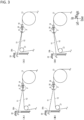
- FIG. 3 depicts a view showing schematically an example of a suitable arrangement pattern of the guide roller 37, the yarn combining guide 20, the yarn combining unit 18, and the yarn feed roller 13 in the combined yarn producing device 1 according to an embodiment of the present invention.
- the ideal yarn path of the second group of yarns Y2 from the guide roller 37 to the yarn feed roller 13 is a straight line. That is, it is preferable that the yarn path of the second group of yarns Y2 until they reach the yarn feed roller 13 from the guide roller 37 via the yarn combining guide 20 and the yarn combining unit 18 is a straight line without any bends along the way.
- the following explanation will be based on this assumption.
- the first group of yarns Y1 has been drawn and heat-set, if the bending of the first group of yarns Y1 becomes large, there is a possibility that the first group of yarns will be damaged, which is not preferable. Further, if the bending of the first group of yarns Y1 is large, there is a possibility that the first group of yarns Y1 may interfere with the heat retention box 30 when being led out from the outlet 30b. On the other hand, if the yarn combining guide 20 is arranged so that the first group of yarns Y1 are not bent in the yarn combining guide 20, there is a possibility that the second group of yarns Y2 will be bent.
- the guide roller 37 is arranged downstream from the guide roller 36 in a yarn traveling direction and above the guide roller 36. In such a manner, even if a distance necessary to change an arrangement direction of the second group of yarns Y2 divided by the yarn dividing guide 11 is secured, it becomes possible to reduce the possible damage to the second group of yarns Y2 while preventing the bending of the first group of yarns Y1 from increasing.
- an ideal arrangement of the yarn combining guide 20, the yarn combining unit 18, the guide roller 37, and the yarn feed roller 13 is an arrangement in which the yarn path of the first group of yarns Y1 from the second heating roller 35 at the most downstream side in a yarn traveling direction of the first group of yarns Y1 in the heat retention box to the yarn feed roller 13 is linear in front view, and the yarn path of the second group of yarns Y2 from the guide roller 37 to the yarn feed roller 13 is linear in front view. That is, it is ideal that, in a front view, the yarn combining guide 20, the yarn combining unit 18, the guide roller 37, and the yarn feed roller 13 are arranged so as to satisfy the conditions that "an upper-sided angle ( ⁇ shown in FIG.
- the yarn path of the first group of yarns Y1 and the yarn path of the second group of yarns Y2 are the same, and the first group of yarns Y1 and the second group of yarns Y2 are not bent in the yarn combining guide 20.
- the preferable arrangement of the yarn combining guide 20, the yarn combining unit 18, and the guide roller 37 is not limited to the arrangement shown in FIG. 1 , but for example, the arrangement shown in (A) to (D) of FIG. 3 may be used.
- the arrangement of the yarn combining guide 20, the yarn combining unit 18, and the guide roller 37 is not limited to the patterns shown in FIG. 1 and (A) to (D) of FIG. 3 , and the arrangement may satisfy that the angle ⁇ is 180 ⁇ 30 [°] (including upper and lower limits), and the angle ⁇ is 180 ⁇ 30 [°] (including upper and lower limits).
- the angle ⁇ is 180 ⁇ 30 [°] (including upper and lower limit values)
- the upper-sided angle ⁇ of the two angles between the yarn path of the first group of yarns Y1 from the second heating roller 35 (see FIG. 1 ) to the yarn combining guide 20 and the yarn path from the yarn combining guide 20 to the yarn feed roller 13 is less than 180°, but the present invention is not limited thereto. If the angle ⁇ is 180 ⁇ 30 [°], it is possible to reduce damage to the first group of yarns Y1. Further, there is little possibility that the first group of yarns Y1 led out from the outlet 30b will interfere with the heat retention box 30.
- the combined yarn producing device 1 includes the yarn combining guide 20 that guides yarns in which the first group of yarns Y1 having been drawn and heat-set and the second group of yarns Y2 having not been drawn and heat-set are combined.
- the yarn combining guide 20 is arranged upstream from both the yarn combining unit 18 and the yarn feed roller 13 in a yarn traveling direction. Then, one set of yarns having the first group of yarns Y1 and the second group of yarns Y2 combined is auxiliary doubled by the yarn combining unit 18 and guided to the yarn feed roller 13. Therefore, the swaying of the second group of yarns Y2 on the yarn feed roller 13 can be suppressed by the first group of yarns Y1, and possible damage to the second group of yarns Y2 can be reduced.
- the yarn combining guide 20 is configured to have a plurality of guide pieces 22 provided along an axial direction of the yarn feed roller 13 to combine and guide one of the first group of yarns Y1 and one of the second group of yarns Y2. Therefore, a plurality of sets of yarns in which the first group of yarns Y1 and the second group of yarns Y2 are combined are guided to the yarn combining unit 18 with a direction along an axis of the yarn feed roller 13 as an arrangement direction. Therefore, swaying of the entire second group of yarns Y2 having not been drawn or heat-set (the entire second group of yarns Y2 in an arrangement direction) can be suppressed by the first group of yarns Y1 having been drawn and heat-set.
- the yarn dividing guide 11 is arranged along a horizontal left-and-right direction, and the yarn feed roller 13 is arranged so that an axial direction extends in a horizontal forward-and-backward direction.
- the second group of yarns Y2 divided by the yarn dividing guide 11 are guided to the guide roller 36 while changing an arrangement direction. Therefore, even if a necessary distance to change an arrangement direction of the second group of yarns Y2 divided by the yarn dividing guide 11 is secured, by arranging the guide roller 37 above the guide roller 36 so that an axial direction is parallel to the guide roller 36, it is possible to suitably reduce damage to the second group of yarns Y2, and suppress breakage of the second group of yarns Y2.
- the guide roller 37, the yarn feed roller 13, and the yarn combining guide 20 are arranged so that the upper-sided angle ⁇ of the two angles between the yarn path of the first group of yarns Y1 from the second heating roller 35 to the yarn combining guide 20 and the yarn path from the yarn combining guide 20 to the yarn combining guide 20 is 180 ⁇ 30 [°] (including upper and lower limit values), and the lower-sided angle ⁇ of the two angles between the yarn path of the second group of yarns Y2 from the guide roller 37 to the yarn combining guide 20 and the yarn path from the yarn combining guide 20 to the yarn feed roller 13 is 180 ⁇ 30 [°] (including upper and lower limit values).
- the guide roller 37 is arranged so that the second group of yarns Y2 guided by the yarn feed roller 13 are located below the first group of yarns Y1 guided by the yarn feed roller 13. In such a manner, the first group of yarns Y1 are positioned above the second group of yarns Y2, and the swaying of the second group of yarns Y2 on the yarn feed roller 13 can be more reliably suppressed.
- the guide roller 36 and the guide roller 37 are arranged in an up-and-down direction along the wall 301 of the heat retention box 30. In such a manner, damage to the second group of yarns Y2 can be reduced while suppressing the enlargement of the combined yarn producing device 1 in a left-and-right direction.
- the guide roller 36 and the guide roller 37 are arranged outside the heat retention box 30, and the second group of yarns Y2 divided by the yarn dividing guide 11 can be guided to the yarn feed roller 13 without entering the heat retention box 30. Therefore, the work of threading the second group of yarns Y2 can be facilitated.
- the combined yarn producing device 1 of an embodiment of the present invention described above is an example of the best mode for carrying out the present invention, but as shown in the following first to fifth modified examples, changes may be made to the combined yarn producing device 1 of an embodiment of the present invention.
- first to fifth modified examples in which changes are made to the combined yarn producing device 1 of an embodiment of the present invention will be described. It is to be noted that the description of the components that are common to the main component of the above-described combined yarn producing device 1 will be omitted, and the components that are different from the main component of the combined yarn producing device 1 will be mainly explained. However, in explaining the combined yarn producing devices 1A to 1E according to each modified example, the main components of each of the combined yarn producing devices 1A to 1E are given the same reference numerals as the main components of the combined yarn producing device 1.
- FIG. 4 depicts a front view of an example of a combined yarn producing device 1A according to a first modified example.
- the combined yarn producing device 1A according to the first modified example is an example of the best mode along with the combined yarn producing device 1 of an embodiment of the present invention.
- the combined yarn producing device 1A according to the first modified example differs from the combined yarn producing device 1 according to an embodiment of the present invention in the arrangement position of the yarn combining unit 18. More specifically, in the combined yarn producing device 1A according to the first modified example, the yarn combining unit 18 is arranged downstream from the yarn feed roller 13 in a yarn traveling direction. More specifically, the yarn combining unit 18 is arranged downstream from the yarn feed roller 13 in a yarn traveling direction and upstream from the yarn feed roller 14 in a yarn traveling direction, and closer to the yarn feed roller 13 than the yarn feed roller 14.
- the yarn combining unit 18 when the yarn combining unit 18 is arranged downstream from the yarn feed roller 13 in a yarn traveling direction, one set of yarns in which the first group of yarns Y1 and the second group of yarns Y2 are combined by the yarn combining guide 20 are guided to the yarn feed roller 13 before being auxiliary doubled. Even in this case, since the first group of yarns Y1 and the second group of yarns Y2 are guided to the yarn feed roller 13 in a combined state, the first group of yarns Y1 having been drawn and heat-set suppress the swaying on the yarn feed roller 13, of the second group of yarns Y2 having not been drawn or heat-set.
- the first group of yarns Y1 suppress the swaying of the second group of yarns Y2 on the yarn feed roller 13, and possible damage to the second group of yarns Y2 can be reduced.
- the arrangement pattern of the guide roller 37, the yarn combining guide 20, and the yarn feed roller 13 is similar to the arrangement pattern shown in (B) of FIG. 3 (however, the arrangement position of the yarn combining unit 18 is different).
- the arrangement pattern of the guide roller 37, the yarn combining guide 20, and the yarn feed roller 13 is not limited to this, and the arrangement pattern shown in FIG. 1 , the arrangement pattern shown in (A) of FIG. 3 , the arrangement pattern shown in (C) of FIG. 3 , or the arrangement pattern shown in (D) of FIG. 3 may be used.
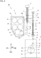
- FIG. 5 depicts a front view of an example of a combined yarn producing device 1B according to a second modified example.
- the combined yarn producing device 1B according to the second modified example differs from the combined yarn producing device 1 according to an embodiment of the present invention in that it does not include the guide roller 37 (the roller that guides the divided second group of yarns Y2 to the yarn feed roller 13 is one of the guide rollers 36). More specifically, in the combined yarn producing device 1B, the second group of yarns Y2 divided by the yarn dividing guide 11 is guided from the guide roller 36 to the yarn feed roller 13 via the yarn combining guide 20 and the yarn combining unit 18. It is to be noted that the second group of yarns Y2 does not pass through any of the first heating rollers 31 to 33 and the second heating rollers 34 and 35.
- the combined yarn producing device 1B does not include the guide roller 37, the yarn path from the guide roller 36 to the yarn feed roller 13 is not linear, and there is a possibility that the second group of yarns Y2 may be bent in the yarn combining guide 20. Further, a distance from the guide roller 36 to the yarn feed roller 13 is greater than a distance from the guide roller 37 to the yarn feed roller 13.
- the combined yarn producing device 1B according to the second modified example differs from the combined yarn producing device 1 according to an embodiment of the present invention and the combined yarn producing device 1A according to the first modified example.
- the first group of yarns Y1 having been drawn and heat-set and the second group of yarns Y2 having not been drawn or heat-set are combined to form one set of yarns
- the first group of yarns Y1 and the second group of yarns Y2 are auxiliary doubled to form combined yarns Y3, and the combined yarns Y3 are guided to the yarn feed roller 13. Therefore, in the combined yarn producing device 1B, similarly to the combined yarn producing device 1 according to an embodiment of the present invention, the swaying of the second group of yarns Y2 on the yarn feed roller 13 can be suppressed by the first group of yarns Y1, and possible damage to the second group of yarns Y2 can be reduced.
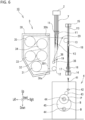
- FIG. 6 depicts a front view of an example of a combined yarn producing device 1C according to a third modified example.
- the combined yarn producing device 1C according to the third modified example differs from the combined yarn producing device 1 according to an embodiment of the present invention in that the yarn combining unit 18 is arranged downstream from the yarn feed roller 13 in a yarn traveling direction, and the guide roller 37 is not provided (the roller that guides the divided second group of yarns Y2 is one of the guide rollers 36).
- the combined yarn producing device 1C is similar to the combined yarn producing device 1A according to the first modified example in that the yarn combining unit 18 is arranged downstream from the yarn feed roller 13 in a yarn traveling direction and is similar to the combined yarn producing device 1B according to the second modified example in that it does not include the guide roller 37.
- the yarn path from the guide roller 36 to the yarn feed roller 13 is not linear, and there is a possibility that the second group of yarns Y2 may be bent in the yarn combining guide 20. Further, a distance from the guide roller 36 to the yarn feed roller 13 is greater than a distance from the guide roller 37 to the yarn feed roller 13.
- the combined yarn producing device 1C according to the third modified example differs from the combined yarn producing device 1 according to an embodiment of the present invention and the combined yarn producing device 1A according to the first modified example.
- the combined yarn producing device 1C according to the third modified example differs from the combined yarn producing device 1 according to an embodiment of the present invention and the combined yarn producing device 1B according to the second modified example.
- the first group of yarns Y1 and the second group of yarns Y2 are guided to the yarn feed roller 13 as one set of combined yarns.
- the swaying of the second group of yarns Y2 on the yarn feed roller 13 can be suppressed by the first group of yarns Y1, and possible damage to the second group of yarns Y2 can be reduced.
- FIG. 7 depicts a front view of an example of a combined yarn producing device 1D according to a fourth modified example.
- the combined yarn producing device 1D according to the fourth modified example differs from the combined yarn producing device 1 according to an embodiment of the present invention in that it does not include the guide roller 37 (the roller that guides the divided second group of yarns Y2 to the yarn feed roller 13 is one of the guide rollers 36) and the guide roller 36 is arranged at an arbitrary position within a range where it does not interfere with the first group of yarns Y1 led out from the outlet 30b.
- the guide roller 36 is arranged at a right side of the outlet 30b and close to the wall 301 of the heat retention box 30, but the present invention is not limited thereto.
- the second group of yarns Y2 divided by the yarn dividing guide 11 are guided to the yarn feed roller 13 via the yarn combining guide 20 and the yarn combining unit 18 from the guide roller 36 arranged at a right side of the outlet 30b of the heat retention box 30 and close to the wall 301 of the heat retention box 30.
- the yarn path guide 38 is arranged upstream from the guide roller 36 in a yarn traveling direction, and an arrangement direction of the second group of yarns Y2 is changed from a horizontal left-and-right direction to a horizontal forward-and-backward direction between the yarn dividing guide 11 and the yarn path guide 38. It is to be noted that the second group of yarns Y2 does not pass through any of the first heating rollers 31 to 33 and the second heating rollers 34 and 35.
- the combined first group of yarns Y1 and second group of yarns Y2 are auxiliary doubled to form combined yarns Y3, and the combined yarns Y3 are guided to yarn feed roller 13. Therefore, in the combined yarn producing device 1D, similarly to the combined yarn producing device 1 according to an embodiment of the present invention, the swaying of the second group of yarns Y2 on the yarn feed roller 13 can be suppressed by the first group of yarns Y1, and possible damage to the second group of yarns Y2 can be reduced.
- the guide roller 36 can be arranged at an arbitrary position within a range where it does not interfere with the first group of yarns Y1 led out from the outlet 30b, as described above.
- the guide roller 36, the yarn combining guide 20, and the yarn feed roller 13 may be arranged in the same positions as the guide roller 37, the yarn combining guide 20, and the yarn feed roller 13 shown in FIG. 1 and (A) to (D) of FIG. 3 .
- the lower-sided angle of the two angles between the yarn path of the second group of yarns Y2 from the guide roller 36 to the yarn combining guide 20 and the yarn path from the yarn combining guide 20 to the yarn feed roller 13 can be set to 180 ⁇ 30 [°]. That is, although it is not possible to secure a sufficient distance to change an arrangement direction of the second group of yarns Y2 divided by the yarn dividing guide 11, it is possible to reduce possible damage to the first group of yarns Y1 and the second group of yarns Y2, especially in the yarn combining guide 20 while suppressing the swaying of the second group of yarns Y2 on the yarn feed roller 13. Further, there is little possibility that the first group of yarns Y1 led out from the outlet 30b will interfere with the heat retention box 30.
- FIG. 8 depicts a front view of an example of a combined yarn producing device 1E according to the fifth modified example.
- the combined yarn producing device 1E according to the fifth modified example does not include the guide roller 37, and the guide roller 36 is arranged at an arbitrary position within a range where it does not interfere with the first group of yarns Y1 led out from the outlet 30b.
- the combined yarn producing device 1E according to the fifth modified example differs from the combined yarn producing device 1 according to an embodiment of the present invention.
- the combined yarn producing device 1E is similar to the combined yarn producing device 1D according to the fourth modified example in that the guide roller 36 is arranged at an arbitrary position within a range where it does not interfere with the first group of yarns Y1 led out from the outlet 30b. Further, the combined yarn producing device 1E is similar to the combined yarn producing device 1A according to the first modified example and the combined yarn producing device 1C according to the third modified example in that the yarn combining unit 18 is arranged downstream from the yarn feed roller 13 in a yarn traveling direction.
- the second group of yarns Y2 divided by the yarn dividing guide 11 is guided to the yarn feed roller 13 via the yarn combining guide 20 from the guide roller 36 arranged at a right side of the outlet 30b of the heat retention box 30 and close to the wall 301 of the heat retention box 30.
- the yarn path guide 38 is arranged upstream from the guide roller 36 in a yarn traveling direction, and an arrangement direction of the second group of yarns Y2 is changed from a horizontal left-and-right direction to a horizontal forward-and-backward direction between the yarn dividing guide 11 and the yarn path guide 38.
- the second group of yarns Y2 does not pass through any of the first heating rollers 31 to 33 and the second heating rollers 34 and 35.
- the first group of yarns Y1 and the second group of yarns Y2 are guided to the yarn feed roller 13 as a combined set of yarns.
- the combined yarn producing device 1E according to the fifth modified example differs from the combined yarn producing device 1 according to an embodiment of the present invention, the combined yarn producing device 1B according to the second modified example, and the combined yarn producing device 1D according to the fourth modified example.
- the first group of yarns Y1 and the second group of yarns Y2 are guided to the yarn feed roller 13 as a combined set of yarns. Therefore, in the combined yarn producing device 1E, similarly to the combined yarn producing device 1 according to an embodiment of the present invention, the swaying of the second group of yarns Y2 on the yarn feed roller 13 can be suppressed by the first group of yarns Y1, and possible damage to the second group of yarns Y2 can be reduced.
- the guide roller 36, the yarn combining guide 20, and the yarn feed roller 13 may be arranged at the same positions as the guide roller 37, the yarn combining guide 20, and the yarn feed roller 13 shown in FIG. 1 and (A) to (D) of FIG. 3 .
- the lower-sided angle of the two angles between the yarn path of the second group of yarns Y2 from the guide roller 36 to the yarn combining guide 20 and the yarn path from the yarn combining guide 20 to the yarn feed roller 13 can be set to 180 ⁇ 30 [°].
Landscapes
- Engineering & Computer Science (AREA)
- Textile Engineering (AREA)
- Mechanical Engineering (AREA)
- Physics & Mathematics (AREA)
- Thermal Sciences (AREA)
- Yarns And Mechanical Finishing Of Yarns Or Ropes (AREA)
Abstract
Description
- The present invention relates to a combined yarn producing device configured to divide a plurality of yarns spun from a spinning unit into a first group of yarns and a second group of yarns so as to perform different processing on the groups of yarns, and thereafter combine the first group of yarns and the second group of yarns.
- Patent Document 1, e.g., discloses a take-up configured to take up a plurality of
yarns 10 spun from aspinning unit 2. InFIG. 2 , e.g., of Patent Document 1, ayarn feed roller 16, five heating rollers 4 (4a to 4e), ayarn feed roller 17, and the like are disclosed as a roller having wound therearound a plurality of yarns spun from thespinning unit 2. The rollers are arranged such that their respective axes are parallel to a forward-and-backward direction. The five heating rollers 4 (4a to 4e) are accommodated in aheat retention box 26, and the five heating rollers 4 (4a to 4e) are configured to perform drawing and heat-setting. Theheat retention box 26 has a slit 26b formed at a bottom at a right side thereof, and has a slit 26c formed at an upper end at a right side thereof. Theyarn feed roller 16 is arranged immediately to a right side of the slit 26b, and theyarn feed roller 17 is arranged immediately to a right side of the slit 26c. A plurality of yarns spun from thespinning unit 2 are arranged along a left-and-right direction, and are fed to theyarn feed roller 16 while an arrangement direction being changed to a forward-and-backward direction. The plurality of yarns fed to theyarn feed roller 16 enter theheat retention box 26 from the slit 26b, travel via the heating rollers 4a to 4e, and leave theheat retention box 26 from the slit 26c. The plurality of yarns fed from the slit 26c are fed to theyarn feed roller 17. The plurality of yarns fed to theyarn feed roller 17 are further fed downward to theyarn feed roller 11. - In recent years, it has been considered that combined yarns (BSY: Bi-Shrinkage Yarn) are produced as a result of combining drawn yarns (FDY: Fully Drawn Yarn) having been drawn and heat-set and partially oriented yarns (POY: Partially Oriented Yarn) having not been drawn or heat-set, through the use of a configuration of a take-up device 100 disclosed in Patent Document 1. It has been known that the drawn yarns and the partially oriented yarns are different in rate of shrinkage from each other, and combined yarns obtained as a result of doubling such two types of yarns different in rate of shrinkage have a good texture.
- Patent Document 1:
Japanese Examined Patent Application Publication No. 2015-187324 - When producing combined yarns through the use of the take-up device 100 disclosed in Patent Document 1, however, the partially oriented yarns having not been drawn or heat-set may sway on rollers to which the yarns are guided because such yarns have unstable tension. If any yarns sway on a roller to which such yarns are guided, the yarns may be damaged due to friction between the yarns and a surface of the roller.
- The present invention has been made in view of the above-described circumstances, and an object thereof is to provide a combined yarn producing device, configured to combine a first group of yarns having been drawn and heat-set and a second group of yarns having not been drawn or heat-set, thereby to produce combined yarns, the combined yarn producing device capable of suppressing swaying of the second group of yarns on rollers to which the yarns are guided so as to reduce possible damage to the ya rns.
- A first aspect of the present invention is a combined yarn producing device configured to perform different processing on a first group of yarns and a second group of yarns out of a plurality of yarns spun from a spinning unit, and thereafter combine the first group of yarns and the second group of yarns thereby to produce combined yarns, the combined yarn producing device comprising:
- a yarn dividing guide configured to divide the plurality of yarns into the first group of yarns and the second group of yarns;
- a first heating roller configured to heat the first group of yarns obtained as a result of dividing the plurality of yarns by the yarn dividing guide;
- a second heating roller arranged downstream from the first heating roller in a yarn traveling direction, the second heating roller configured to draw and heat-set the first group of yarns between the first heating roller and the second heating roller;
- a heat retention box configured to accommodate the first heating roller and the second heating roller having a first opening formed at a lower part of a wall thereof and a second opening formed at an upper part of the wall thereof;
- a first yarn feed roller configured to cause the first group of yarns obtained as a result of dividing the plurality of yarns by the yarn dividing guide to enter the heat retention box from the first opening;
- a second yarn feed roller configured such that the first group of yarns caused to enter the heat retention box from the first opening, pass through the first heating roller and the second heating roller, and thereafter leave the heat retention box from the second opening are guided to the second yarn feed roller;
- a guide roller configured to guide the second group of yarns obtained as a result of dividing the plurality of yarns by the yarn dividing guide to the second yarn feed roller without passing through either the first heating roller or the second heating roller;
- a yarn doubling unit arranged downstream from the second yarn feed roller in a yarn traveling direction, the yarn doubling unit configured to double the first group of yarns and the second group of yarns;
- a yarn combining unit arranged upstream from the yarn doubling unit in a yarn traveling direction, the yarn combining unit configured to auxiliary double the first group of yarns and the second group of yarns; and
- a yarn combining guide having a plurality of guide portions arranged along an axial direction of the second yarn feed roller downstream from any of the second heating roller and the guide roller in a yarn traveling direction as well as upstream from any of the yarn combining unit and the second yarn feed roller in a yarn traveling direction, the plurality of guide portions configured to combine and guide the first group of yarns having been drawn and heat-set and the second group of yarns having not been drawn or heat-set.
- According to the above-described first aspect of the combined yarn producing device, the first group of yarns having been drawn and heat-set and the second group of yarns having not been drawn or heat-set are combined and guided to the second yarn feed roller by the plurality of guide portions arranged along an axial direction of the second yarn feed roller. The movement of the first group of yarns and the second group of yarns in an arrangement direction is restricted by the plurality of guide portions, and therefore, auxiliary doubling of the first group of yarns and the second group of yarns is more likely to occur in comparison to a case on the second yarn feed roller. As a result, swaying of the second group of yarns on the second yarn feed roller can be suppressed by the first group of yarns, and thereby, possible damage to the second group of yarns can be reduced.
- It is to be noted that the yarn combining unit may be arranged upstream from the second yarn feed roller in a yarn traveling direction, or may be arranged downstream from the second yarn feed roller in a yarn traveling direction.
- A second aspect of the present invention is the combined yarn producing device, wherein it is more preferable that
- the guide roller is arranged such that
- a lower-sided angle out of two angles formed between a yarn path of the second group of yarns from the guide roller to the yarn combining guide and a yarn path from the yarn combining guide to the second yarn feed roller is 180 ± 30 [°].
- According to the above-described second aspect of the combined yarn producing device, the lower-sided angle out of the two angles formed between a yarn path of the second group of yarns from the guide roller to the yarn combining guide and a yarn path from the yarn combining guide to the second yarn feed roller is 180 ± 30 [°], and therefore, possible damage to the second group of yarns can be reduced. More specifically, it is preferable that a yarn path of the second group of yarns from the guide roller to the second yarn feed roller is linear. When the yarn combining guide is arranged downstream from the guide roller in a yarn traveling direction as well as upstream from the second yarn feed roller in a yarn traveling direction, however, there is a probability that the second group of yarns would be bent at the yarn combining guide, and the second group of yarns would be damaged. In this regard, according to the above-described second aspect of the combined yarn producing device, even if the yarn combining guide is arranged downstream from the guide roller in a yarn traveling direction as well as upstream from the second yarn feed roller in a yarn traveling direction, possible damage to the second group of yarns can be reduced.
- A third aspect of the present invention is the combined yarn producing device, wherein it is more preferable that
the yarn combining unit is arranged upstream from the second yarn feed roller in a yarn traveling direction, and is configured to auxiliary double the combined first group of yarns and second group of yarns and guide the auxiliary doubled yarns to the second yarn feed roller. - According to the above-described third aspect of the combined yarn producing device, the yarn combining unit is arranged downstream from the yarn combining guide in a yarn traveling direction as well as upstream from the second yarn feed roller in a yarn traveling direction, and therefore, the combined first group of yarns and second group of yarns are auxiliary doubled, and the auxiliary doubled yarns are guided to the second yarn feed roller. As a result, in comparison to a case where yarns obtained as a result of simply combining but not doubling the first group of yarns and the second group of yarns are guided to the second yarn feed roller, it becomes possible to further suppress swaying of the second group of yarns Y2 on the second yarn feed roller.
- A fourth aspect of the present invention is the combined yarn producing device, wherein it is more preferable that
- the plurality of yarns spun from the spinning unit are arranged along one horizontal direction, and the yarn dividing guide is arranged along the one horizontal direction, wherein
- the second yarn feed roller is arranged such that an axial direction thereof is horizontal and is perpendicular to the one horizontal direction, and wherein
- the guide roller includes
- a first guide roller arranged so as to be parallel in axial direction to the second yarn feed roller, the first guide roller configured such that the second group of yarns obtained as a result of dividing the plurality of yarns by the yarn dividing guide are guided to the first guide roller while an arrangement direction of the second group of yarns being changed, and
- a second guide roller arranged downstream from the first guide roller in a yarn traveling direction, and arranged above the first guide roller so as to be parallel in axial direction to the first guide roller.
- According to the above-described fourth aspect of the combined yarn producing device, the yarn dividing guide is arranged along the one horizontal direction, and the second yarn feed roller is arranged such that an axial direction thereof is horizontal and is perpendicular to the one horizontal direction. The second group of yarns obtained as a result of dividing the plurality of yarns by the yarn dividing guide are, therefore, guided to the first guide roller while an arrangement direction thereof being changed. However, the second guide roller is arranged above the first guide roller so as to be parallel in axial direction to each other, and therefore, even if a distance necessary to change an arrangement direction of the second group of yarns obtained as a result of dividing the plurality of yarns by the yarn dividing guide is secured, possible damage to the second group of yarns can be suitably reduced.
- To explain in detail, when a distance necessary to change an arrangement direction of the second group of yarns obtained as a result of dividing the plurality of yarns by the yarn dividing guide is secured, a position at which the first guide roller is arranged becomes lower. In such a case, even without any second guide roller arranged, if the yarn combining guide is arranged along a yarn path of the second group of yarns between the first guide roller and the second yarn feed roller, it is possible to suppress bending of the second group of yarns, and to reduce possible damage to the second group of yarns. In such a case, however, it is necessary to bend the first group of yarns caused to leave from the second opening by the yarn combining guide. Although the first group of yarns have been drawn and heat-set, if such first group of yarns are bent largely, there is a probability that the first group of yarns would be damaged, which is not preferable. Further, if the first group of yarns are bent largely, there is a probability that the first group of yarns would interfere with the heat retention box when being caused to leave the heat retention box from the second opening. When the second guide roller is arranged downstream from the first guide roller in a yarn traveling direction and is arranged above the first guide roller, therefore, even if a distance necessary to change an arrangement direction of the second group of yarns obtained as a result of dividing the plurality of yarns by the yarn dividing guide is secured, possible damage to the second group of yarns can be reduced while the first group of yarns being prevented from being bent too much.
- A fifth aspect of the present invention is the combined yarn producing device, wherein it is more preferable that
- the second guide roller, the second yarn feed roller, and the yarn combining guide are arranged such that
- an upper-sided angle out of two angles formed between a yarn path of the first group of yarns from a most downstream roller in a yarn traveling direction of the first group of yarns in the heat retention box to the yarn combining guide and a yarn path from the yarn combining guide to the second yarn feed roller is 180 ± 30 [°] (including upper and lower limit values), and
- a lower-sided angle out of two angles formed between a yarn path of the second group of yarns from the second guide roller to the yarn combining guide and a yarn path from the yarn combining guide to the second yarn feed roller is 180 ± 30 [°] (including upper and lower limit values).
- According to the above-described fifth aspect of the combined yarn producing device, even when a distance necessary to change an arrangement direction of the second group of yarns obtained as a result of dividing the plurality of yarns by the yarn dividing guide is secured, it is possible to reduce possible damage to the first group of yarns and the second group of yarns until the second group of yarns are guided to the second yarn feed roller while suppressing swaying of the second group of yarns Y on the yarn feed roller. Further, it is also possible to prevent the first group of yarns from interfering with the heat retention box.
- A sixth aspect of the present invention is the combined yarn producing device, wherein it is more preferable that
the second guide roller is arranged such that the second group of yarns guided by the second yarn feed roller are located below the first group of yarns guided by the second yarn feed roller. - According to the above-described sixth aspect of the combined yarn producing device, the second group of yarns guided by the second yarn feed roller are located below the first group of yarns guided by the second yarn feed roller, and therefore, the first group of yarns Y1 are positioned above the second group of yarns Y2, and swaying of the second group of yarns Y2 on the
yarn feed roller 13 can be more reliably suppressed. - A seventh aspect of the present invention is the combined yarn producing device, wherein it is more preferable that
the first guide roller and the second guide roller are arranged in an up-and-down direction along a wall of the heat retention box. - According to the above-described seventh aspect of the combined yarn producing device, the first guide roller and the second guide roller are arranged in an up-and-down direction along the wall, and therefore, damage to the second group of yarns can be reduced while any enlargement of the combined yarn producing device in the one horizontal direction being suppressed.
- An eighth aspect of the present invention is the combined yarn producing device, wherein it is more preferable that
- the first guide roller and the second guide roller are arranged outside the heat retention box, and
- the second group of yarns obtained as a result of dividing the plurality of yarns by the yarn dividing guide are guided to the second yarn feed roller without being caused to enter the heat retention box.
- According to the above-described eighth aspect of the combined yarn producing device, it is only necessary to perform threading so that the second group of yarns fed from the guide rollers are guided by the yarn feed roller without being introduced into the heat retention box, and therefore, the threading work is facilitated.
- According to the present invention, it is possible to provide a combined yarn producing device, configured to combine a first group of yarns having been drawn and heat-set and a second group of yarns having not been drawn or heat-set, thereby to produce combined yarns, the combined yarn producing device capable of suppressing swaying of the second group of yarns on rollers to which the yarns are guided so as to reduce possible damage to the yarns.
- Further, the combined yarn producing device according to the present invention does not necessarily include all the above-described first to eighth aspects of configuration. The invention according to the above-described first aspect of the combined yarn producing device, e.g., does not need to have all the above-described second to eighth aspects of configuration. Further, the combined yarn producing device according to the present invention may be obtained as a result of combining arbitrarily the above-described first aspect of configuration and any of the above-described second to eighth aspects of configuration to such an extent that consistency can be achieved. It is to be noted that, upon any arbitrary combination of the above-described first aspect of configuration and any of the above-described second to eighth aspects of configuration, it is not essential to combine the above-described first aspect of configuration and all the above-described second to eighth aspects of configurations but acceptable to combine the above-described first aspect of configuration and a part of the above-described second to eighth aspects of configuration to such an extent that consistency can be achieved.
-
-
FIG. 1 depicts a front view of an example of a combined yarn producing device according to an embodiment of the present invention. -
FIG. 2 depicts a perspective view of an example of a yarn combining guide according to an embodiment of the present invention. -
FIG. 3 depicts a view showing schematically an example of a suitable arrangement pattern of a guide roller, a yarn combining guide, a yarn combining unit, and a yarn feed roller in a combined yarn producing device according to an embodiment of the present invention. -
FIG. 4 depicts a front view of an example of a combined yarn producing device according to a first modified example. -
FIG. 5 depicts a front view of an example of a combined yarn producing device according to a second modified example . -
FIG. 6 depicts a front view of an example of a combined yarn producing device according to a third modified example . -
FIG. 7 depicts a front view of an example of a combined yarn producing device according to a fourth modified example . -
FIG. 8 depicts a front view of an example of a combined yarn producing device according to a fifth modified example . - Hereinafter, embodiments for carrying out the present invention will be described with reference to the drawings. For convenience of explanation, an up-and-down direction, left-and-right direction, and forward-and-backward direction are defined as shown in
FIG. 1 andFIGS. 3 to 8 to be described later. - First, an example of a combined yarn producing device 1 according to an embodiment of the present invention (hereinafter, referred to as an "embodiment of the present invention") will be described mainly with reference to
FIG. 1. FIG. 1 depicts a front view of an example of a combined yarn producing device 1 according to an embodiment of the present invention. - The combined yarn producing device 1 divides a plurality of yarns Y as synthetic fiber yarns formed by solidifying molten resin continuously spun from a
spinning unit 2 into a first group of yarns Y1 and a second group of yarns Y2 and causes the first group of yarns Y1 to be subject to drawing treatment and heat-setting so that the first group of yarns Y1 and the second group of yarns Y2 become different from each other in rate of shrinkage. More specifically, the combined yarn producing device 1 causes the first group of yarns Y1 to be subject to drawing treatment and heat-setting to obtain drawn yarns (FDY: Fully Drawn Yarn), and does not cause the second group of yarns Y2 to be subject to either drawing treatment or heat-setting to obtain partially oriented yarns (POY: Partially Oriented Yarn). Thereafter, the combined yarn producing device 1 combines the first group of yarns Y1, which are drawn yarns (FDY), and the second group of yarns, Y2, which are partially oriented yarns (POY), to produce combined yarns Y3 (BSY: Bi-Shrinkage Yarn). The combined yarns Y3 composed of two types of yarns Y1 and Y2 different in rate of shrinkage from each other have been known for good texture. In addition, in the present specification, when the type of yarn is not particularly limited, it is simply referred to as yarn Y. - The combined yarn producing device 1 includes, as its main components, a
yarn dividing guide 11, a spunyarn drawing unit 3,yarn feed rollers 12 to 15, guiderollers yarn combining guide 20, ayarn combining unit 18, aninterlacer 16, aspooling unit 4, and the like. Hereinafter, these main components will be explained in the above order. - The
yarn dividing guide 11 is, e.g., a comb-shaped guide, and divides all of the plurality of yarns Y spun from thespinning unit 2 into a first group of yarns Y1 and a second group of yarns Y2. The plurality of yarns Y spun from thespinning unit 2 are arranged along a horizontal left-and-right direction. Theyarn dividing guide 11 is arranged below thespinning unit 2 along a horizontal left-and-right direction. All of the plurality of yarns Y spun from thespinning unit 2 are evenly divided by theyarn dividing guide 11 into the first group of yarns Y1 and the second group of yarns Y2. In an embodiment of the present invention, e.g., there are 16 yarns Y spun from thespinning unit 2, which are divided into a first group of eight yarns Y1 and a second group of eight yarns Y2, and eventually, eight combined yarns Y3 are produced. - The spun
yarn drawing unit 3 is a device for drawing and heat-setting the first group of yarns Y1, which are divided by theyarn dividing guide 11, among the plurality of yarns Y spun from thespinning unit 2. The spunyarn drawing unit 3 is arranged below thespinning unit 2 and theyarn dividing guide 11 and in front of thespinning unit 2 and theyarn dividing guide 11. - The spun
yarn drawing unit 3 includes aheat retention box 30 and a plurality of (five in an embodiment of the present invention)heating rollers 31 to 35 accommodated inside theheat retention box 30. Theheating rollers 31 to 35 are arranged so that their rotational axes extend horizontally in a forward-and-backward direction, and are rotationally driven by an electric motor (not shown). - The
heating rollers 31 to 35 have built-in heaters (not shown), which heat the yarns Y wound around the circumferential surfaces of theheating rollers 31 to 35. Theheating rollers 31 to 35 all have approximately the same outer diameter. - Among the five
heating rollers 31 to 35, the threefirst heating rollers 31 to 33 at an upstream side in a yarn traveling direction are pre-heating rollers for pre-heating the first group of yarns Y1 before drawing. The surface temperature of thefirst heating rollers 31 to 33 is set to a temperature higher than the glass transition point of the yarns Y (e.g., approximately 80°C). On the other hand, among the fiveheating rollers 31 to 35, the twosecond heating rollers second heating rollers first heating rollers 31 to 33. - In an embodiment of the present invention, among the five
heating rollers 31 to 35, threeheating rollers 31 to 33 at an upstream side in a yarn traveling direction are used as pre-heating rollers, and twoheating rollers heating rollers heating rollers 33 to 35 at a downstream side in a yarn traveling direction are used as heat-setting rollers. - Among the three
first heating rollers 31 to 33, thefirst heating roller 31 at the most upstream in a yarn traveling direction is arranged below the remaining twofirst heating rollers first heating roller 32 at the second in a yarn traveling direction and thefirst heating roller 33 at the third in a yarn traveling direction are arranged adjacent to each other in a left-and-right direction. The axis of thefirst heating roller 32 at the second in a yarn traveling direction is located to the right of the axis of thefirst heating roller 31 at the most upstream in a yarn traveling direction. The axis of thefirst heating roller 33 at the third in a yarn traveling direction is located to the left of the axis of thefirst heating roller 31 at the most upstream in a yarn traveling direction. - The two
second heating rollers first heating rollers 31 to 33. Thesecond heating roller 34 at an upstream side in a yarn traveling direction is arranged above and adjacent to thefirst heating roller 32 at the second in a yarn traveling direction. Thesecond heating roller 35 at a downstream side in a yarn traveling direction is arranged above thefirst heating roller 33 at the third in a yarn traveling direction. It is to be noted that thesecond heating roller 35 at a downstream side in a yarn traveling direction is shifted upward from thesecond heating roller 34 at an upstream side in a yarn traveling direction. More specifically, the axis of thesecond heating roller 35 at a downstream side in a yarn traveling direction is located above the axis of thesecond heating roller 34 at an upstream side in a yarn traveling direction. - Further, the rotational speed of the
second heating rollers first heating rollers 31 to 33. As a result, the first group of yarns Y1 reach thesecond heating rollers first heating rollers 31 to 33, and becomes a drawn yarn due to the difference in the yarn feeding speed between thefirst heating roller 33 and thesecond heating roller 34. Further, the first group of yarns Y1 are heat-set in a drawn state by thesecond heating rollers heat retention box 30 from anoutlet 30b to be described later, and fed to theyarn feed roller 13 to be described later. - It is to be noted that, in an embodiment of the present invention, among the five
heating rollers 31 to 35, the yarn is drawn due to the difference in yarn feeding speed between theheating roller 33 and theheating roller 34, but the invention is not limited to this. For example, the yarn may be drawn due to the difference in the yarn feeding speed between theheating roller 32 and theheating roller 33, and the point where the difference in yarn feeding speed is provided to obtain a drawn yarn may be changed as appropriate. - In this way, the first group of yarns Y1 can be drawn and heat-set while the five
heating rollers 31 to 35 are arranged in a compact and dense manner in a left-and-right direction and an up-and-down direction. - The
heat retention box 30 is box-shaped and has an open front side and accommodates a plurality ofheating rollers 31 to 35, and has a door (not shown) that opens and closes the open front side. Aninlet 30a for introducing the first group of yarns Y1 fed from theyarn feed roller 12 to be described later, to the inside of theheat retention box 30 is formed at the lower end of theright wall 301 of the box-shapedheat retention box 30. Further, anoutlet 30b for leading the first group of yarns Y1 having been drawn and heat-set to the outside of theheat retention box 30 is formed at an upper end of thewall 301. - The above-described "
inlet 30a" corresponds to a "first opening" of the present invention, and the above-described "outlet 30b" corresponds to a "second opening" of the present invention. - The
yarn feed rollers 12 to 15 are rotationally driven by an electric motor (not shown). Theyarn feed rollers yarn feed rollers - The
yarn feed roller 12 is a roller configured to feed the first group of yarns Y1 divided by theyarn dividing guide 11 to the spunyarn drawing unit 3, and is arranged at approximately the same height position as theinlet 30a formed at a lower end of thewall 301 of theheat retention box 30 and at right side of theinlet 30a. The first group of yarns Y1 divided by theyarn dividing guide 11 are caused to travel toward theyarn feed roller 12. A yarn path guide 19 is arranged upstream from theyarn feed roller 12 in a yarn traveling direction, and an arrangement direction of the first group of yarns Y1 is changed from a horizontal left-and-right direction to a horizontal forward-and-backward direction between theyarn dividing guide 11 and the yarn path guide 19. That is, although the first group of yarns Y1 divided by theyarn dividing guide 11 are arranged in a horizontal left-and-right direction, an arrangement direction of the first group of yarns Y1 is changed to a horizontal forward-and-backward direction until they reach the yarn path guide 19 from theyarn dividing guide 11. The first group of yarns Y1 fed from theyarn feed roller 12 are introduced into theheat retention box 30 and guided to thefirst heating roller 31 in a horizontal state or a substantially horizontal state. - It is to be noted that, as described above, an arrangement direction of the first group of yarns Y1 is changed until they reach the yarn path guide 19 from the
yarn dividing guide 11. However, since theyarn feed roller 12 is arranged at approximately the same height as theinlet 30a formed at a lower end of theright wall 301 of theheat retention box 30, a distance from theyarn dividing guide 11 to theyarn feed roller 12 can be made as long as possible. Therefore, it is possible to secure a sufficient distance to change an arrangement direction of the first group of yarns Y1 divided by theyarn dividing guide 11, and reduce possible damage to the first group of yarns Y1. - The
yarn feed roller 13 is arranged at approximately the same height as theoutlet 30b formed at an upper end of thewall 301 of theheat retention box 30, and at a right side of both theoutlet 30b and theyarn dividing guide 11. In an embodiment of the present invention, theyarn feed roller 13 is arranged such that the upper surface of thesecond heating roller 35, which is the most downstream from the plurality ofheating rollers 31 to 35, and the upper surface of theyarn feed roller 13 are horizontal or approximately horizontal, but this is not essential. That is, the first group of yarns Y1 having been drawn and heat-set are less likely to be damaged than the second group of yarns Y2 having not been drawn or heat-set. Therefore, the yarn path of the first group of yarns Y1 from thesecond heating roller 35 to theyarn feed roller 13 may be a downward slope or an upward slope within a range where the first group of yarns Y1 do not interfere with theheat retention box 30 when being led out from theoutlet 30b. - The
yarn feed roller 14 is a roller configured to guide the yarns Y fed from theyarn feed roller 13 to theyarn feed roller 15 arranged downstream from theyarn feed roller 14 in a yarn traveling direction. The yarns Y fed from theyarn feed roller 13 to theyarn feed roller 14 are combined yarns Y3 having the first group of yarns Y1 and the second group of yarns Y2 auxiliary doubled by ayarn combining unit 18 to be described later. - A yarn path guide 17 is arranged upstream from the
yarn feed roller 14 in a yarn traveling direction, and an arrangement direction of the combined yarns Y3 fed from theyarn feed roller 13 is changed from a horizontal forward-and-backward direction to a horizontal left-and-right direction. That is, an arrangement direction of the combined yarns Y3 fed from theyarn feed roller 13 is a horizontal forward-and-backward direction, but an arrangement direction of the combined yarns Y3 is changed to a horizontal left-right direction between theyarn feed roller 13 and the yarn path guide 17. - The combined yarns Y3 fed from the
yarn feed roller 14 are guided to theyarn feed roller 15 at a downstream side of theyarn feed roller 14 in a yarn traveling direction. The combined yarns Y3 fed from theyarn feed roller 15 are fed to thespooling unit 4 while an arrangement direction being changed from a left-and-right direction to a forward-and-backward direction. - The
guide rollers guide rollers wall 301 of theheat retention box 30. More specifically, theguide roller 36 is arranged directly above theyarn feed roller 12 and close to thewall 301 of theheat retention box 30. Theguide roller 37 is arranged on a right side of theoutlet 30b and close to thewall 301 of theheat retention box 30 so that the roller surface is below the first group of yarns Y1 led out from theoutlet 30b. - The second group of yarns Y2 divided by the
yarn dividing guide 11 are caused to travel toward theguide roller 36. A yarn path guide 38 is arranged upstream from theguide roller 36 in a yarn traveling direction, and an arrangement direction of the second group of yarns Y2 is changed from a horizontal left-and-right direction to a horizontal forward-and-backward direction between theyarn dividing guide 11 and theguide roller 36. That is, although an arrangement direction of the first group of yarns Y1 divided by theyarn dividing guide 11 is a horizontal left-and-right direction, an arrangement direction of the second group of yarns Y2 is changed to a horizontal forward-and-backward direction until they reach the yarn path guide 38 from theyarn dividing guide 11. The second group of yarns Y2 fed from theguide roller 36 are guided to theguide roller 37 without being introduced into theheat retention box 30. That is, the second group of yarns Y2 fed from theguide roller 36 are guided to theyarn feed roller 13 through theguide roller 37 without passing through any of thefirst heating rollers 31 to 33 and thesecond heating rollers guide roller 36 are guided to theyarn feed roller 13 through theguide roller 37, theyarn combining guide 20, and theyarn combining unit 18. - It is to be noted that, as described above, an arrangement direction of the second group of yarns Y2 is changed until they reach the yarn path guide 38 from the
yarn dividing guide 11. However, since theguide roller 36 is arranged directly above theyarn feed roller 12, a distance from theyarn dividing guide 11 to the yarn path guide 38 can be made as long as possible. Therefore, it is possible to secure a sufficient distance to change an arrangement direction of the second group of yarns Y2 divided by theyarn dividing guide 11, reduce possible damage to the second group of yarns Y2. - The
guide roller 37 guides the second group of yarns Y2 fed from theguide roller 36 upstream from theguide roller 37 in a yarn traveling direction to theyarn feed roller 13 at a downstream side in a yarn traveling direction of theguide roller 37 via theyarn combining guide 20 and theyarn combining unit 18. - In addition, when the
guide rollers guide rollers guide rollers guide rollers guide rollers guide rollers guide roller 37 is provided as a driven roller and theguide roller 37 comes into contact with the first group of yarns Y1, there is a possibility that the first group of yarns Y1 and the second group of yarns Y2 may become entangled due to the speed difference between the first group of yarns Y1 and the guide roller. From this point of view, it is preferable to use theguide rollers 36 and 37 (especially the guide roller 37) as drive rollers. In addition, when theguide rollers - In addition, it is sufficient that threading is performed so that the second group of yarns Y2 fed from the
guide roller 36 are guided by theyarn feed roller 13 without being introduced into theheat retention box 30, which facilitates the threading work. However, it is not essential that the second group of yarns Y2 fed from theguide roller 36 be guided to theyarn feed roller 13 without being introduced into theheat retention box 30. For example, after introducing the second group of yarns Y2 fed from theguide roller 36 into theheat retention box 30, the second group of yarns Y2 may be led out from theoutlet 30b and introduced to theyarn feed roller 13 without passing through any of thefirst heating rollers 31 to 33 and thesecond heating rollers yarn feed roller 13 without being drawn or heat-set. - The above-described "
guide roller 36" corresponds to a "first guide roller" of the present invention, and the above-described "guide roller 37" corresponds to a "second guide roller" of the present invention. - The
yarn combining guide 20 is arranged upstream from theyarn feed roller 13 in a yarn traveling direction and downstream from both thesecond heating roller 35 and theguide roller 37 in a yarn traveling direction. Theyarn combining guide 20 has a comb-like shape, e.g., and is configured as shown in, e.g.,FIG. 2 . -
FIG. 2 depicts a perspective view of an example of theyarn combining guide 20. Theyarn combining guide 20 includes a plurality ofguide pieces 22 arranged in a row, and aguide rail 26 that supports theguide pieces 22. Ayarn storage space 24 is formed between oneguide piece 22 among the plurality ofguide pieces 22 and anotherguide piece 22 adjacent to the oneguide piece 22. Theyarn combining guide 20 is arranged such that an arrangement direction of the plurality ofguide pieces 22 extends in a horizontal forward-and-backward direction. That is, theyarn combining guide 20 is arranged so that an arrangement direction of theguide pieces 22 and a direction of a rotational axis of theyarn feed roller 13 are horizontal and parallel. - In the
yarn combining guide 20, a state in which the first group of yarns Y1 having been drawn and heat-set, and the second group of yarns Y2 having not been drawn or heat-set, are stacked one by one and combined by passing through the sameyarn storage space 24 is created. Then, the first group of yarns Y1 and the second group of yarns Y2 are guided to theyarn feed roller 13 via theyarn combining unit 18 in a combined state. In other words, one of the first group of yarns Y1 and one of the second group of yarns Y2 become one set of yarns, which are guided to the sameyarn storage space 24 and guided to theyarn feed roller 13 via theyarn combining unit 18. In an embodiment of the present invention, e.g., eight sets of yarns, each of which is a combination of the first group of yarns Y1 and the second group of yarns Y2, are guided to differentyarn storage spaces 24, respectively. - Since the tension of the second group of yarns Y2 having not been drawn or heat-set are unstable, yarn swaying may occur on the
yarn feed roller 13. When the yarns sway on theyarn feed roller 13, there is a possibility that the second group of yarns Y2 are damaged due to friction between the second group of yarns Y2 and the roller surface of theyarn feed roller 13. Therefore, in an embodiment of the present invention, the first group of yarns Y1, which has been drawn and heat-set, and the second group of yarns Y2, which has not been drawn or heat-set, are combined to form one set of yarns. After that, the first group of yarns Y1 and the second group of yarns Y2 are auxiliary doubled by theyarn combining unit 18 to form combined yarns Y3, and the combined yarns Y3 are guided to theyarn feed roller 13. In such a manner, the first group of yarns Y1 suppresses swaying of the second group of yarns Y2 on theyarn feed roller 13, and possible damage to the second group of yarns Y2 can be reduced. - In addition, since the
yarn combining guide 20 is arranged so that an arrangement direction of the plurality ofguide pieces 22 extends in a horizontal forward-and-backward direction, a plurality of sets of yarns in which the first group of yarns Y1 and the second group of yarns Y2 are combined can be guided to differentyarn storage spaces 24 respectively. In such a manner, all of the plurality of second group of yarns Y2 are combined with the first group of yarns Y1 and guided to theyarn storage space 24. Therefore, on theyarn feed roller 13, it is possible to suppress the swaying of the plurality of second group of yarns Y2 having been combined with the first group of yarns Y1 and has not been drawn or heat-set. Further, since the second group of yarns Y2 come into contact with a side portion and a bottom portion of theguide piece 22, it is possible to further suppress the swaying of the second group of yarns Y2 on theyarn feed roller 13. - The above-described "guide
piece 22" corresponds to a "guide portion" of the present invention. - The
yarn combining guide 20 guides one of the first group of yarns Y1 and one of the second group of yarns Y2 in the sameyarn storage space 24, and does not inject compressed air to the first group of yarns Y1 and the second group of yarns Y2. Therefore, the yarns having the first group of yarns Y1 and the second group of yarns Y2 combined by theyarn combining guide 20 are yarns having simply been combined, and are not yarns having been doubled in a strict sense until they are auxiliary doubled by theyarn combining unit 18. However, in the present specification, for convenience, the yarns having the first group of yarns Y1 and the second group of yarns Y2 combined by theyarn combining guide 20 will also be described as an auxiliary doubled yarn. - Further, it is preferable that the
yarn combining guide 20 is arranged so that an arrangement direction of theguide pieces 22 and a direction of a rotational axis of theyarn feed roller 13 are horizontal and parallel. In such a manner, theguide pieces 22 restrict the movement of the first group of yarns Y1 and the second group of yarns Y2 in an arrangement direction (a forward-and-backward direction inFIG. 1 ). Thus, as compared to on the secondyarn feed roller 13, auxiliary doubling of the first group of yarns Y1 and the second group of yarns Y2 is more likely to occur. However, if one set of yarns having the first group of yarns Y1 and the second group of yarns Y2 combined is guided by the sameyarn storage space 24, it is not essential that an arrangement direction of theguide pieces 22 be parallel to a direction of a rotational axis of theyarn feed roller 13. - Returning to
FIG. 1 , theyarn combining unit 18 is arranged upstream from theyarn feed roller 13 in a yarn traveling direction and downstream from both thesecond heating roller 35 and theguide roller 37 in a yarn traveling direction. Theyarn combining unit 18 auxiliary doubles a set of yarns in which the first group of yarns Y1 and the second group of yarns Y2 are combined in theyarn combining guide 20 at an upstream side of theinterlacer 16 in a yarn traveling direction to be described later. Theyarn combining unit 18 is a yarn doubling auxiliary device that injects low-pressure compressed air whose injection pressure is set lower than that of theinterlacer 16 onto a plurality of sets of yarns in which the first group of yarns Y1 and the second group of yarns Y2 are combined, mixes the combined first group of yarns Y1 and second group of yarns Y2 by the action of the low-pressure compressed air to auxiliary double the first group of yarns Y1 and the second group of yarns Y2. The degree of doubling of the first group of yarns Y1 and the second group of yarns Y2 by theyarn combining unit 18 is weaker than that of theinterlacer 16, and theyarn combining unit 18 plays the role of auxiliary doubling yarns. In theyarn combining unit 18, the first group of yarns Y1 and the second group of yarns Y2 are auxiliary doubled to produce combined yarns Y3. - In this way, after the
yarn combining guide 20 combines the first group of yarns Y1 and the second group of yarns Y2 into one set of yarns, theyarn combining unit 18 auxiliary doubles the first group of yarns Y1 and the second group of yarns. As a result, it becomes possible to further suppress the swaying of the second group of yarns Y2 on theyarn feed roller 13. - The
interlacer 16 is arranged downstream from theyarn feed roller 13 in a yarn traveling direction. In an embodiment of the present invention, theinterlacer 16 is arranged downstream from theyarn feed roller 14 in a yarn traveling direction and upstream from theyarn feed roller 15 in a yarn traveling direction, and closer to theyarn feed roller 14 than theyarn feed roller 15. Theinterlacer 16 is an interlacing device that injects high-pressure compressed air (fluid) whose injection pressure is set higher than that of theyarn combining unit 18, and instantaneously creates knots in the yarn Y by the action of this high-pressure compressed air to double the first group of yarns Y1 and the second group of yarns Y2. As described above, the combined yarns Y3, which have already been auxiliary doubled by theyarn combining unit 18, are firmly doubled by theinterlacer 16. The combined yarns Y3, in which the first group of yarns Y1 and the second group of yarns Y2 are firmly doubled by theinterlacer 16, are fed to thespooling unit 4 via theyarn feed roller 15. - The above-described "
interlacer 16" corresponds to a "yarn doubling unit" of the present invention. - The spooling
unit 4 includes a plurality of fulcrum guides 41, a plurality oftraverse devices 42, acontact roller 43, twobobbin holders 44, and aturret 45. - The plurality of fulcrum guides 41 and the plurality of
traverse devices 42 are arranged side by side so as to correspond to each other in a forward-and-backward direction, and are shown overlapping in a forward-and-backward direction inFIG. 1 . The plurality of combined yarns Y3 fed to thespooling unit 4 are traversed in a forward-and-backward direction by the correspondingtraverse devices 42, centering on the plurality of fulcrum guides 41. - The
contact roller 43 is configured to contact the surfaces of a plurality of packages P, apply a predetermined contact pressure, and adjust the shape of the packages P. The plurality of packages P are arranged side by side in a forward-and-backward direction, and are shown overlapping in a forward-and-backward direction inFIG. 1 . Thebobbin holder 44 extends in a forward-and-backward direction, and is configured to be able to mount a plurality of bobbins B in a state where it is lined up in a forward-and-backward direction. - The
bobbin holder 44 is rotationally driven by an electric motor (not shown). Theturret 45 supports the twobobbin holders 44 in a cantilevered manner, and is configured to be rotationally driven by an electric motor (not shown). In thespooling unit 4, the positions of the twobobbin holders 44 are switched between an upper winding position and a lower standby position when theturret 45 is rotationally driven. - The spooling
unit 4 forms a plurality of packages P by winding a plurality of combined yarns Y3 onto a plurality of bobbins B by rotating thebobbin holder 44 located at an upper winding position. When the plurality of packages P are completed, theturret 45 is rotated to switch the positions of the twobobbin holders 44. Then, the plurality of combined yarns Y3 are wound around the plurality of bobbins B mounted on thebobbin holder 44 having been newly moved to the winding position. - In addition, in an embodiment of the present invention, although the
spooling unit 4 has twobobbin holders 44, it is not limited to this, and the number ofbobbin holders 44 may be one. - Next, the arrangement of the
guide roller 37, theyarn combining guide 20, theyarn combining unit 18, and theyarn feed roller 13 will be explained with reference toFIGS. 1 and3. FIG. 3 depicts a view showing schematically an example of a suitable arrangement pattern of theguide roller 37, theyarn combining guide 20, theyarn combining unit 18, and theyarn feed roller 13 in the combined yarn producing device 1 according to an embodiment of the present invention. - Considering possible damage to the second group of yarns Y2, the ideal yarn path of the second group of yarns Y2 from the
guide roller 37 to theyarn feed roller 13 is a straight line. That is, it is preferable that the yarn path of the second group of yarns Y2 until they reach theyarn feed roller 13 from theguide roller 37 via theyarn combining guide 20 and theyarn combining unit 18 is a straight line without any bends along the way. The following explanation will be based on this assumption. - First, the significance of providing the
guide roller 37 will be explained. As described above, by making a distance from theyarn dividing guide 11 to the yarn path guide 38 as long as possible, a sufficient distance to change an arrangement direction of the second group of yarns Y2 divided by theyarn dividing guide 11 can be secured. However, if the second group of yarns Y2 are guided from theguide roller 36 to theyarn combining guide 20 without providing theguide roller 37, it is difficult to suitably reduce possible damage to the second group of yarns Y2. More specifically, if theyarn combining guide 20 is arranged so that the second group of yarns Y2 are not bent, there is a possibility that the first group of yarns Y1 led out from theoutlet 30b are bent in theyarn combining guide 20. Although the first group of yarns Y1 has been drawn and heat-set, if the bending of the first group of yarns Y1 becomes large, there is a possibility that the first group of yarns will be damaged, which is not preferable. Further, if the bending of the first group of yarns Y1 is large, there is a possibility that the first group of yarns Y1 may interfere with theheat retention box 30 when being led out from theoutlet 30b. On the other hand, if theyarn combining guide 20 is arranged so that the first group of yarns Y1 are not bent in theyarn combining guide 20, there is a possibility that the second group of yarns Y2 will be bent. Therefore, in an embodiment of the present invention, theguide roller 37 is arranged downstream from theguide roller 36 in a yarn traveling direction and above theguide roller 36. In such a manner, even if a distance necessary to change an arrangement direction of the second group of yarns Y2 divided by theyarn dividing guide 11 is secured, it becomes possible to reduce the possible damage to the second group of yarns Y2 while preventing the bending of the first group of yarns Y1 from increasing. - Next, assuming that the
guide roller 37 is arranged downstream from theguide roller 36 in a yarn traveling direction and above theguide roller 36, a suitable arrangement of theguide roller 37, theyarn combining guide 20, theyarn combining unit 18, and theyarn feed roller 13 will be explained. - For example, as shown in
FIG. 1 , an ideal arrangement of theyarn combining guide 20, theyarn combining unit 18, theguide roller 37, and theyarn feed roller 13 is an arrangement in which the yarn path of the first group of yarns Y1 from thesecond heating roller 35 at the most downstream side in a yarn traveling direction of the first group of yarns Y1 in the heat retention box to theyarn feed roller 13 is linear in front view, and the yarn path of the second group of yarns Y2 from theguide roller 37 to theyarn feed roller 13 is linear in front view. That is, it is ideal that, in a front view, theyarn combining guide 20, theyarn combining unit 18, theguide roller 37, and theyarn feed roller 13 are arranged so as to satisfy the conditions that "an upper-sided angle (α shown inFIG. 3 to be described later) among the two angles between the yarn path of the first group of yarns Y1 from thesecond heating roller 35 at the most downstream side in a yarn traveling direction of the first group of yarns Y1 to theyarn combining guide 20 in the heat retention box is 180°" and that "a lower-sided angle (β shown inFIG. 3 to be described later) among the two angles between the yarn path of the second group of yarns Y2 from theguide roller 37 to theyarn combining guide 20 and the yarn path from theyarn combining guide 20 to theyarn feed roller 13 is 180°". InFIG. 1 , at an upstream side of theyarn combining guide 20 in a yarn traveling direction, the yarn path of the first group of yarns Y1 and the yarn path of the second group of yarns Y2 are the same, and the first group of yarns Y1 and the second group of yarns Y2 are not bent in theyarn combining guide 20. - However, the preferable arrangement of the
yarn combining guide 20, theyarn combining unit 18, and theguide roller 37 is not limited to the arrangement shown inFIG. 1 , but for example, the arrangement shown in (A) to (D) ofFIG. 3 may be used. - (A) of
FIG. 3 depicts a view showing schematically an arrangement pattern when, in a front view, the upper-sided angle α among the two angles between the yarn path of the first group of yarns Y1 from the second heating roller 35 (seeFIG. 1 ) to theyarn combining guide 20 and the yarn path from theyarn combining guide 20 to theyarn feed roller 13 is less than 180°, and the lower-sided angle β among the two angles between the yarn path of the second group of yarns Y2 from theguide roller 37 to theyarn combining guide 20 and the yarn path from theyarn combining guide 20 to theyarn feed roller 13 is 180°. - (B) of
FIG. 3 depicts a view showing schematically an arrangement pattern when, in a front view, the upper-sided angle α among the two angles between the yarn path of the first group of yarns Y1 from the second heating roller 35 (seeFIG. 1 ) to theyarn combining guide 20 and the yarn path from theyarn combining guide 20 to theyarn feed roller 13 is less than 180°, and the lower-sided angle β among the two angles between the yarn path of the second group of yarns Y2 from theguide roller 37 to theyarn combining guide 20 and the yarn path from theyarn combining guide 20 to theyarn feed roller 13 is less than 180°. That is, although the ideal angle β is 180°, it is not necessarily limited to 180°. However, in view of possible damage to the second group of yarns Y2, it is preferable that the angle β is 150° or more. - (C) of
FIG. 3 depicts a view showing schematically an arrangement pattern when, in a front view, the upper-sided angle α among the two angles between the yarn path of the first group of yarns Y1 from the second heating roller 35 (seeFIG. 1 ) to theyarn combining guide 20 and the yarn path from theyarn combining guide 20 to theyarn feed roller 13 is less than 180°, and the lower-sided angle β among the two angles between the yarn path of the second group of yarns Y2 from theguide roller 37 to theyarn combining guide 20 and the yarn path from theyarn combining guide 20 to theyarn feed roller 13 is greater than 180°. That is, the angle β may be greater than 180°. However, in view of possible damage to the second group of yarns Y2, it is preferable that the angle β is 210° or less. It is to be noted that, since it is physically impossible for the yarn path of the second group of yarns Y2 to be above the yarn path of the first group of yarns Y1, if the angle β is 180° or more, the yarn path of the first group of yarns Y1 and the yarn path of the second group of yarns Y2 are the same, or the yarn path of the first group of yarns Y1 is above the yarn path of the second group of yarns Y2. - (D) of
FIG. 3 depicts a view showing schematically an arrangement pattern when, in a front view, the upper-sided angle α among the two angles between the yarn path of the first group of yarns Y1 from the second heating roller 35 (seeFIG. 1 ) to theyarn combining guide 20 and the yarn path from theyarn combining guide 20 to theyarn feed roller 13 is greater than 180°, and the lower-sided angle β among the two angles between the yarn path of the second group of yarns Y2 from theguide roller 37 to theyarn combining guide 20 and the yarn path from theyarn combining guide 20 to theyarn feed roller 13 is less than 180°. That is, the angle α may be greater than 180°. However, also in this case, in view of possible damage to the second group of yarns Y2, it is preferable that the angle β is 150° or more. - The arrangement of the
yarn combining guide 20, theyarn combining unit 18, and theguide roller 37 is not limited to the patterns shown inFIG. 1 and (A) to (D) ofFIG. 3 , and the arrangement may satisfy that the angle α is 180 ± 30 [°] (including upper and lower limits), and the angle β is 180 ± 30 [°] (including upper and lower limits). - In this way, in a front view, if the angle β is 180 ± 30 [°] (including upper and lower limit values), it is possible to reduce possible damage to the second group of yarns Y2 until it is guided to the yarn feed roller 13 (more specifically, the yarn combining guide 20). More specifically, even if a sufficient distance to change an arrangement direction of the second group of yarns Y2 divided by the yarn dividing guide 11 (see
FIG. 1 ) is secured, it is possible to reduce possible damage to the second group of yarns Y2, especially in theyarn combining guide 20, while suppressing the swaying of the second group of yarns Y2 on theyarn feed roller 13. - In addition, in (A) to (D) of
FIG. 3 described above, the upper-sided angle α of the two angles between the yarn path of the first group of yarns Y1 from the second heating roller 35 (seeFIG. 1 ) to theyarn combining guide 20 and the yarn path from theyarn combining guide 20 to theyarn feed roller 13 is less than 180°, but the present invention is not limited thereto. If the angle α is 180 ± 30 [°], it is possible to reduce damage to the first group of yarns Y1. Further, there is little possibility that the first group of yarns Y1 led out from theoutlet 30b will interfere with theheat retention box 30. - It is to be noted that, if the roller at the most downstream side among the plurality of
rollers 31 to 35 (seeFIG. 1 ) arranged inside theheat retention box 30 is not thesecond heating roller 35 but another roller, "the yarn path of the first group of yarns Y1 from the second heating roller 35 (seeFIG. 1 ) to theyarn combining guide 20" is replaced with "the yarn path of the first group of yarns Y1 from the other roller to theyarn combining guide 20". - As explained above, according to an embodiment of the present invention, the combined yarn producing device 1 includes the
yarn combining guide 20 that guides yarns in which the first group of yarns Y1 having been drawn and heat-set and the second group of yarns Y2 having not been drawn and heat-set are combined. Theyarn combining guide 20 is arranged upstream from both theyarn combining unit 18 and theyarn feed roller 13 in a yarn traveling direction. Then, one set of yarns having the first group of yarns Y1 and the second group of yarns Y2 combined is auxiliary doubled by theyarn combining unit 18 and guided to theyarn feed roller 13. Therefore, the swaying of the second group of yarns Y2 on theyarn feed roller 13 can be suppressed by the first group of yarns Y1, and possible damage to the second group of yarns Y2 can be reduced. - Further, the
yarn combining guide 20 is configured to have a plurality ofguide pieces 22 provided along an axial direction of theyarn feed roller 13 to combine and guide one of the first group of yarns Y1 and one of the second group of yarns Y2. Therefore, a plurality of sets of yarns in which the first group of yarns Y1 and the second group of yarns Y2 are combined are guided to theyarn combining unit 18 with a direction along an axis of theyarn feed roller 13 as an arrangement direction. Therefore, swaying of the entire second group of yarns Y2 having not been drawn or heat-set (the entire second group of yarns Y2 in an arrangement direction) can be suppressed by the first group of yarns Y1 having been drawn and heat-set. - Further, the
yarn dividing guide 11 is arranged along a horizontal left-and-right direction, and theyarn feed roller 13 is arranged so that an axial direction extends in a horizontal forward-and-backward direction. The second group of yarns Y2 divided by theyarn dividing guide 11 are guided to theguide roller 36 while changing an arrangement direction. Therefore, even if a necessary distance to change an arrangement direction of the second group of yarns Y2 divided by theyarn dividing guide 11 is secured, by arranging theguide roller 37 above theguide roller 36 so that an axial direction is parallel to theguide roller 36, it is possible to suitably reduce damage to the second group of yarns Y2, and suppress breakage of the second group of yarns Y2. - In addition, in a front view, the
guide roller 37, theyarn feed roller 13, and theyarn combining guide 20 are arranged so that the upper-sided angle α of the two angles between the yarn path of the first group of yarns Y1 from thesecond heating roller 35 to theyarn combining guide 20 and the yarn path from theyarn combining guide 20 to theyarn combining guide 20 is 180 ± 30 [°] (including upper and lower limit values), and the lower-sided angle β of the two angles between the yarn path of the second group of yarns Y2 from theguide roller 37 to theyarn combining guide 20 and the yarn path from theyarn combining guide 20 to theyarn feed roller 13 is 180 ± 30 [°] (including upper and lower limit values). By arranging theguide roller 37, theyarn feed roller 13, and theyarn combining guide 20 in this way, even if a sufficient distance to change an arrangement direction of the second group of yarns Y2 divided by theyarn dividing guide 11 is secured, it is possible to reduce possible damage to the first group of yarns Y1 and the second group of yarns Y2 especially in theyarn combining guide 20 while suppressing the swaying of the second group of yarns Y2 on theyarn feed roller 13. Further, there is little possibility that the first group of yarns Y1 led out from theoutlet 30b will interfere with theheat retention box 30. - Further, the
guide roller 37 is arranged so that the second group of yarns Y2 guided by theyarn feed roller 13 are located below the first group of yarns Y1 guided by theyarn feed roller 13. In such a manner, the first group of yarns Y1 are positioned above the second group of yarns Y2, and the swaying of the second group of yarns Y2 on theyarn feed roller 13 can be more reliably suppressed. - Further, the
guide roller 36 and theguide roller 37 are arranged in an up-and-down direction along thewall 301 of theheat retention box 30. In such a manner, damage to the second group of yarns Y2 can be reduced while suppressing the enlargement of the combined yarn producing device 1 in a left-and-right direction. - Further, the
guide roller 36 and theguide roller 37 are arranged outside theheat retention box 30, and the second group of yarns Y2 divided by theyarn dividing guide 11 can be guided to theyarn feed roller 13 without entering theheat retention box 30. Therefore, the work of threading the second group of yarns Y2 can be facilitated. - The combined yarn producing device 1 of an embodiment of the present invention described above is an example of the best mode for carrying out the present invention, but as shown in the following first to fifth modified examples, changes may be made to the combined yarn producing device 1 of an embodiment of the present invention. Below, first to fifth modified examples in which changes are made to the combined yarn producing device 1 of an embodiment of the present invention will be described. It is to be noted that the description of the components that are common to the main component of the above-described combined yarn producing device 1 will be omitted, and the components that are different from the main component of the combined yarn producing device 1 will be mainly explained. However, in explaining the combined
yarn producing devices 1A to 1E according to each modified example, the main components of each of the combinedyarn producing devices 1A to 1E are given the same reference numerals as the main components of the combined yarn producing device 1. -
FIG. 4 depicts a front view of an example of a combinedyarn producing device 1A according to a first modified example. The combinedyarn producing device 1A according to the first modified example is an example of the best mode along with the combined yarn producing device 1 of an embodiment of the present invention. The combinedyarn producing device 1A according to the first modified example differs from the combined yarn producing device 1 according to an embodiment of the present invention in the arrangement position of theyarn combining unit 18. More specifically, in the combinedyarn producing device 1A according to the first modified example, theyarn combining unit 18 is arranged downstream from theyarn feed roller 13 in a yarn traveling direction. More specifically, theyarn combining unit 18 is arranged downstream from theyarn feed roller 13 in a yarn traveling direction and upstream from theyarn feed roller 14 in a yarn traveling direction, and closer to theyarn feed roller 13 than theyarn feed roller 14. - In this way, when the
yarn combining unit 18 is arranged downstream from theyarn feed roller 13 in a yarn traveling direction, one set of yarns in which the first group of yarns Y1 and the second group of yarns Y2 are combined by theyarn combining guide 20 are guided to theyarn feed roller 13 before being auxiliary doubled. Even in this case, since the first group of yarns Y1 and the second group of yarns Y2 are guided to theyarn feed roller 13 in a combined state, the first group of yarns Y1 having been drawn and heat-set suppress the swaying on theyarn feed roller 13, of the second group of yarns Y2 having not been drawn or heat-set. Therefore, even in the combinedyarn producing device 1A, similarly to the combined yarn producing device 1 according to an embodiment of the present invention, the first group of yarns Y1 suppress the swaying of the second group of yarns Y2 on theyarn feed roller 13, and possible damage to the second group of yarns Y2 can be reduced. - In particular, since the roller surface of the
guide roller 37 is below the first group of yarns Y1 led out from theoutlet 30b, it is thought that the second group of yarns Y2 fed from theguide roller 37 to theyarn combining guide 20 is located below the first group of yarns Y1 led out of theheat retention box 30 and fed to theyarn combining guide 20. Therefore, in theyarn storage space 24 and theyarn feed roller 13, it is thought that the second group of yarns Y2 are pressed down from above by the first group of yarns Y1, and the swaying of the second group of yarns Y2 on theyarn feed roller 13 can be further suppressed. - It is to be noted that, in
FIG. 4 showing the first modified example, the arrangement pattern of theguide roller 37, theyarn combining guide 20, and theyarn feed roller 13 is similar to the arrangement pattern shown in (B) ofFIG. 3 (however, the arrangement position of theyarn combining unit 18 is different). However, the arrangement pattern of theguide roller 37, theyarn combining guide 20, and theyarn feed roller 13 is not limited to this, and the arrangement pattern shown inFIG. 1 , the arrangement pattern shown in (A) ofFIG. 3 , the arrangement pattern shown in (C) ofFIG. 3 , or the arrangement pattern shown in (D) ofFIG. 3 may be used. By arranging theguide roller 37, theyarn combining guide 20, and theyarn feed roller 13 in this manner, similarly to the combined yarn producing device 1 according to an embodiment of the present invention, even if a sufficient distance to change an arrangement direction of the second group of yarns Y2 divided by theyarn dividing guide 11 is secured, it is possible to reduce possible damage to the first group of yarns Y1 and the second group of yarns Y2 especially in theyarn combining guide 20 while suppressing the swaying of the second group of yarns Y2 on theyarn feed roller 13. Further, there is little possibility that the first group of yarns Y1 led out from theoutlet 30b will interfere with theheat retention box 30. -
FIG. 5 depicts a front view of an example of a combinedyarn producing device 1B according to a second modified example. The combinedyarn producing device 1B according to the second modified example differs from the combined yarn producing device 1 according to an embodiment of the present invention in that it does not include the guide roller 37 (the roller that guides the divided second group of yarns Y2 to theyarn feed roller 13 is one of the guide rollers 36). More specifically, in the combinedyarn producing device 1B, the second group of yarns Y2 divided by theyarn dividing guide 11 is guided from theguide roller 36 to theyarn feed roller 13 via theyarn combining guide 20 and theyarn combining unit 18. It is to be noted that the second group of yarns Y2 does not pass through any of thefirst heating rollers 31 to 33 and thesecond heating rollers - In this way, when the combined
yarn producing device 1B does not include theguide roller 37, the yarn path from theguide roller 36 to theyarn feed roller 13 is not linear, and there is a possibility that the second group of yarns Y2 may be bent in theyarn combining guide 20. Further, a distance from theguide roller 36 to theyarn feed roller 13 is greater than a distance from theguide roller 37 to theyarn feed roller 13. In this respect, the combinedyarn producing device 1B according to the second modified example differs from the combined yarn producing device 1 according to an embodiment of the present invention and the combinedyarn producing device 1A according to the first modified example. However, even in the combinedyarn producing device 1B according to the second modified example, after the first group of yarns Y1 having been drawn and heat-set and the second group of yarns Y2 having not been drawn or heat-set are combined to form one set of yarns, the first group of yarns Y1 and the second group of yarns Y2 are auxiliary doubled to form combined yarns Y3, and the combined yarns Y3 are guided to theyarn feed roller 13. Therefore, in the combinedyarn producing device 1B, similarly to the combined yarn producing device 1 according to an embodiment of the present invention, the swaying of the second group of yarns Y2 on theyarn feed roller 13 can be suppressed by the first group of yarns Y1, and possible damage to the second group of yarns Y2 can be reduced. -
FIG. 6 depicts a front view of an example of a combined yarn producing device 1C according to a third modified example. The combined yarn producing device 1C according to the third modified example differs from the combined yarn producing device 1 according to an embodiment of the present invention in that theyarn combining unit 18 is arranged downstream from theyarn feed roller 13 in a yarn traveling direction, and theguide roller 37 is not provided (the roller that guides the divided second group of yarns Y2 is one of the guide rollers 36). That is, the combined yarn producing device 1C is similar to the combinedyarn producing device 1A according to the first modified example in that theyarn combining unit 18 is arranged downstream from theyarn feed roller 13 in a yarn traveling direction and is similar to the combinedyarn producing device 1B according to the second modified example in that it does not include theguide roller 37. - That is, in the combined yarn producing device 1C, similarly to the combined
yarn producing device 1B according to the second modified example, the yarn path from theguide roller 36 to theyarn feed roller 13 is not linear, and there is a possibility that the second group of yarns Y2 may be bent in theyarn combining guide 20. Further, a distance from theguide roller 36 to theyarn feed roller 13 is greater than a distance from theguide roller 37 to theyarn feed roller 13. In this respect, the combined yarn producing device 1C according to the third modified example differs from the combined yarn producing device 1 according to an embodiment of the present invention and the combinedyarn producing device 1A according to the first modified example. Further, before the first group of yarns Y1 and the second group of yarns Y2 are auxiliary doubled, the first group of yarns Y1 and the second group of yarns Y2 are guided to theyarn feed roller 13 as one set of combined yarns. In this respect, the combined yarn producing device 1C according to the third modified example differs from the combined yarn producing device 1 according to an embodiment of the present invention and the combinedyarn producing device 1B according to the second modified example. However, even in the combined yarn producing device 1C according to the third modified example, the first group of yarns Y1 and the second group of yarns Y2 are guided to theyarn feed roller 13 as one set of combined yarns. Therefore, in the combined yarn producing device 1C, similarly to the combined yarn producing device 1 according to an embodiment of the present invention, the swaying of the second group of yarns Y2 on theyarn feed roller 13 can be suppressed by the first group of yarns Y1, and possible damage to the second group of yarns Y2 can be reduced. -
FIG. 7 depicts a front view of an example of a combinedyarn producing device 1D according to a fourth modified example. The combinedyarn producing device 1D according to the fourth modified example differs from the combined yarn producing device 1 according to an embodiment of the present invention in that it does not include the guide roller 37 (the roller that guides the divided second group of yarns Y2 to theyarn feed roller 13 is one of the guide rollers 36) and theguide roller 36 is arranged at an arbitrary position within a range where it does not interfere with the first group of yarns Y1 led out from theoutlet 30b. It is to be noted that, inFIG. 7 , theguide roller 36 is arranged at a right side of theoutlet 30b and close to thewall 301 of theheat retention box 30, but the present invention is not limited thereto. - In the combined
yarn producing device 1D, the second group of yarns Y2 divided by theyarn dividing guide 11 are guided to theyarn feed roller 13 via theyarn combining guide 20 and theyarn combining unit 18 from theguide roller 36 arranged at a right side of theoutlet 30b of theheat retention box 30 and close to thewall 301 of theheat retention box 30. In this case, the yarn path guide 38 is arranged upstream from theguide roller 36 in a yarn traveling direction, and an arrangement direction of the second group of yarns Y2 is changed from a horizontal left-and-right direction to a horizontal forward-and-backward direction between theyarn dividing guide 11 and the yarn path guide 38. It is to be noted that the second group of yarns Y2 does not pass through any of thefirst heating rollers 31 to 33 and thesecond heating rollers - Even in the combined
yarn producing device 1D according to the fourth modified example, after the first group of yarns Y1 having been drawn and heat-set and the second group of yarns Y2 having not been drawn nor heat-set are combined to form one set of yarns, the combined first group of yarns Y1 and second group of yarns Y2 are auxiliary doubled to form combined yarns Y3, and the combined yarns Y3 are guided toyarn feed roller 13. Therefore, in the combinedyarn producing device 1D, similarly to the combined yarn producing device 1 according to an embodiment of the present invention, the swaying of the second group of yarns Y2 on theyarn feed roller 13 can be suppressed by the first group of yarns Y1, and possible damage to the second group of yarns Y2 can be reduced. - It is to be noted that, in
FIG. 7 showing the fourth modified example, theguide roller 36 can be arranged at an arbitrary position within a range where it does not interfere with the first group of yarns Y1 led out from theoutlet 30b, as described above. Theguide roller 36, theyarn combining guide 20, and theyarn feed roller 13 may be arranged in the same positions as theguide roller 37, theyarn combining guide 20, and theyarn feed roller 13 shown inFIG. 1 and (A) to (D) ofFIG. 3 . In such a manner, in a front view, the lower-sided angle of the two angles between the yarn path of the second group of yarns Y2 from theguide roller 36 to theyarn combining guide 20 and the yarn path from theyarn combining guide 20 to theyarn feed roller 13 can be set to 180 ± 30 [°]. That is, although it is not possible to secure a sufficient distance to change an arrangement direction of the second group of yarns Y2 divided by theyarn dividing guide 11, it is possible to reduce possible damage to the first group of yarns Y1 and the second group of yarns Y2, especially in theyarn combining guide 20 while suppressing the swaying of the second group of yarns Y2 on theyarn feed roller 13. Further, there is little possibility that the first group of yarns Y1 led out from theoutlet 30b will interfere with theheat retention box 30. -
FIG. 8 depicts a front view of an example of a combinedyarn producing device 1E according to the fifth modified example. Similarly to the combinedyarn producing device 1D according to the fourth modified example, the combinedyarn producing device 1E according to the fifth modified example does not include theguide roller 37, and theguide roller 36 is arranged at an arbitrary position within a range where it does not interfere with the first group of yarns Y1 led out from theoutlet 30b. Further, in this point, the combinedyarn producing device 1E according to the fifth modified example differs from the combined yarn producing device 1 according to an embodiment of the present invention. That is, the combinedyarn producing device 1E is similar to the combinedyarn producing device 1D according to the fourth modified example in that theguide roller 36 is arranged at an arbitrary position within a range where it does not interfere with the first group of yarns Y1 led out from theoutlet 30b. Further, the combinedyarn producing device 1E is similar to the combinedyarn producing device 1A according to the first modified example and the combined yarn producing device 1C according to the third modified example in that theyarn combining unit 18 is arranged downstream from theyarn feed roller 13 in a yarn traveling direction. - That is, in the combined
yarn producing device 1E, the second group of yarns Y2 divided by theyarn dividing guide 11 is guided to theyarn feed roller 13 via theyarn combining guide 20 from theguide roller 36 arranged at a right side of theoutlet 30b of theheat retention box 30 and close to thewall 301 of theheat retention box 30. In this case, similarly to the combinedyarn producing device 1D according to the fourth modified example, the yarn path guide 38 is arranged upstream from theguide roller 36 in a yarn traveling direction, and an arrangement direction of the second group of yarns Y2 is changed from a horizontal left-and-right direction to a horizontal forward-and-backward direction between theyarn dividing guide 11 and the yarn path guide 38. It is to be noted that the second group of yarns Y2 does not pass through any of thefirst heating rollers 31 to 33 and thesecond heating rollers yarn producing device 1E, before the first group of yarns Y1 and the second group of yarns Y2 are auxiliary doubled, the first group of yarns Y1 and the second group of yarns Y2 are guided to theyarn feed roller 13 as a combined set of yarns. In this respect, the combinedyarn producing device 1E according to the fifth modified example differs from the combined yarn producing device 1 according to an embodiment of the present invention, the combinedyarn producing device 1B according to the second modified example, and the combinedyarn producing device 1D according to the fourth modified example. However, even in the combinedyarn producing device 1E according to the fifth modified example, the first group of yarns Y1 and the second group of yarns Y2 are guided to theyarn feed roller 13 as a combined set of yarns. Therefore, in the combinedyarn producing device 1E, similarly to the combined yarn producing device 1 according to an embodiment of the present invention, the swaying of the second group of yarns Y2 on theyarn feed roller 13 can be suppressed by the first group of yarns Y1, and possible damage to the second group of yarns Y2 can be reduced. - In addition, in
FIG. 8 showing the fifth modified example, similarly to the fourth modified example, theguide roller 36, theyarn combining guide 20, and theyarn feed roller 13 may be arranged at the same positions as theguide roller 37, theyarn combining guide 20, and theyarn feed roller 13 shown inFIG. 1 and (A) to (D) ofFIG. 3 . In such a manner, in a front view, the lower-sided angle of the two angles between the yarn path of the second group of yarns Y2 from theguide roller 36 to theyarn combining guide 20 and the yarn path from theyarn combining guide 20 to theyarn feed roller 13 can be set to 180 ± 30 [°]. That is, although it is not possible to secure a sufficient distance to change an arrangement direction of the second group of yarns Y2 divided by theyarn dividing guide 11, it is possible to reduce possible damage to the first group of yarns Y1 and the second group of yarns Y2, especially in theyarn combining guide 20 while suppressing the swaying of the second group of yarns Y2 on theyarn feed roller 13. Further, there is little possibility that the first group of yarns Y1 led out from theoutlet 30b will interfere with theheat retention box 30. -
- 1
- Combined yarn producing device
- 2
- Spinning unit
- 11
- Yarn dividing guide
- 12
- First yarn feed roller
- 13
- Second yarn feed roller
- 16
- Interlacer
- 18
- Yarn combining unit
- 20
- Yarn combining guide
- 30
- heat retention box
- 30a
- Inlet
- 30b
- Outlet
- 31 to 33
- First heating roller
- 34, 35
- Second heating roller
- 36
- First guide roller
- 37
- Second guide roller
- 301
- Wall
- Y
- Yarn
- Y1
- First group of yarns
- Y2
- Second group of yarns
- Y3
- Combined yarns
Claims (8)
- A combined yarn producing device configured to perform different processing on a first group of yarns and a second group of yarns out of a plurality of yarns spun from a spinning unit, and thereafter combine the first group of yarns and the second group of yarns thereby to produce combined yarns, the combined yarn producing device comprising:a yarn dividing guide configured to divide the plurality of yarns into the first group of yarns and the second group of yarns;a first heating roller configured to heat the first group of yarns obtained as a result of dividing the plurality of yarns by the yarn dividing guide;a second heating roller arranged downstream from the first heating roller in a yarn traveling direction, the second heating roller configured to draw and heat-set the first group of yarns between the first heating roller and the second heating roller;a heat retention box configured to accommodate the first heating roller and the second heating roller having a first opening formed at a lower part of a wall thereof and a second opening formed at an upper part of the wall thereof;a first yarn feed roller configured to cause the first group of yarns obtained as a result of dividing the plurality of yarns by the yarn dividing guide to enter the heat retention box from the first opening;a second yarn feed roller configured such that the first group of yarns caused to enter the heat retention box from the first opening, pass through the first heating roller and the second heating roller, and thereafter leave the heat retention box from the second opening are guided to the second yarn feed roller;a guide roller configured to guide the second group of yarns obtained as a result of dividing the plurality of yarns by the yarn dividing guide to the second yarn feed roller without passing through either the first heating roller or the second heating roller;a yarn doubling unit arranged downstream from the second yarn feed roller in a yarn traveling direction, the yarn doubling unit configured to double the first group of yarns and the second group of yarns;a yarn combining unit arranged upstream from the yarn doubling unit in a yarn traveling direction, the yarn combining unit configured to auxiliary double the first group of yarns and the second group of yarns; anda yarn combining guide having a plurality of guide portions arranged along an axial direction of the second yarn feed roller downstream from any of the second heating roller and the guide roller in a yarn traveling direction as well as upstream from any of the yarn combining unit and the second yarn feed roller in a yarn traveling direction, the plurality of guide portions configured to combine and guide the first group of yarns having been drawn and heat-set and the second group of yarns having not been drawn or heat-set.
- The combined yarn producing device according to claim 1, whereinthe guide roller is arranged such thata lower-sided angle out of two angles formed between a yarn path of the second group of yarns from the guide roller to the yarn combining guide and a yarn path from the yarn combining guide to the second yarn feed roller is 180 ± 30 [°],
- The combined yarn producing device according to claim 1 or 2, wherein
the yarn combining unit is arranged upstream from the second yarn feed roller in a yarn traveling direction, and is configured to auxiliary double the combined first group of yarns and second group of yarns and guide the auxiliary doubled yarns to the second yarn feed roller. - The combined yarn producing device according to any one of claims 1 to 3, whereinthe plurality of yarns spun from the spinning unit are arranged along one horizontal direction, and the yarn dividing guide is arranged along the one horizontal direction, whereinthe second yarn feed roller is arranged such that an axial direction thereof is horizontal and is perpendicular to the one horizontal direction, and whereinthe guide roller includesa first guide roller arranged so as to be parallel in axial direction to the second yarn feed roller, the first guide roller configured such that the second group of yarns obtained as a result of dividing the plurality of yarns by the yarn dividing guide are guided to the first guide roller while an arrangement direction of the second group of yarns being changed, anda second guide roller arranged downstream from the first guide roller in a yarn traveling direction, and arranged above the first guide roller so as to be parallel in axial direction to the first guide roller.
- The combined yarn producing device according to claim 4, whereinthe second guide roller, the second yarn feed roller, and the yarn combining guide are arranged such thatan upper-sided angle out of two angles formed between a yarn path of the first group of yarns from a most downstream roller in a yarn traveling direction of the first group of yarns in the heat retention box to the yarn combining guide and a yarn path from the yarn combining guide to the second yarn feed roller is 180 ± 30 [°] (including upper and lower limit values), anda lower-sided angle out of two angles formed between a yarn path of the second group of yarns from the second guide roller to the yarn combining guide and a yarn path from the yarn combining guide to the second yarn feed roller is 180 ± 30 [°] (including upper and lower limit values).
- The combined yarn producing device according to claim 4 or 5, wherein
the second guide roller is arranged such that the second group of yarns guided by the second yarn feed roller are located below the first group of yarns guided by the second yarn feed roller. - The combined yarn producing device according to any one of claims 4 to 6, wherein
the first guide roller and the second guide roller are arranged in an up-and-down direction along a wall of the heat retention box. - The combined yarn producing device according to any one of claims 4 to 7, whereinthe first guide roller and the second guide roller are arranged outside the heat retention box, andthe second group of yarns obtained as a result of dividing the plurality of yarns by the yarn dividing guide are guided to the second yarn feed roller without being caused to enter the heat retention box.
Applications Claiming Priority (3)
| Application Number | Priority Date | Filing Date | Title |
|---|---|---|---|
| JP2021172516A JP7759763B2 (en) | 2021-10-21 | 2021-10-21 | Yarn threading unit and blended yarn manufacturing device |
| JP2022113250A JP7833980B2 (en) | 2022-07-14 | 2022-07-14 | Blended fiber yarn manufacturing equipment |
| PCT/JP2022/038163 WO2023068150A1 (en) | 2021-10-21 | 2022-10-13 | Mixed yarn production device |
Publications (2)
| Publication Number | Publication Date |
|---|---|
| EP4421225A1 true EP4421225A1 (en) | 2024-08-28 |
| EP4421225A4 EP4421225A4 (en) | 2025-10-08 |
Family
ID=86059148
Family Applications (1)
| Application Number | Title | Priority Date | Filing Date |
|---|---|---|---|
| EP22883454.5A Pending EP4421225A4 (en) | 2021-10-21 | 2022-10-13 | DEVICE FOR PRODUCING MIXED YARN |
Country Status (2)
| Country | Link |
|---|---|
| EP (1) | EP4421225A4 (en) |
| WO (1) | WO2023068150A1 (en) |
Family Cites Families (6)
| Publication number | Priority date | Publication date | Assignee | Title |
|---|---|---|---|---|
| JPS59130309A (en) * | 1983-01-14 | 1984-07-26 | Teijin Ltd | Production of yarn mix of different shrinkage |
| JP2694714B2 (en) * | 1993-05-20 | 1997-12-24 | 鐘紡株式会社 | Different shrinkage mixed yarn manufacturing method |
| JP5832945B2 (en) * | 2012-03-28 | 2015-12-16 | Tmtマシナリー株式会社 | Blended yarn production equipment |
| JP6450214B2 (en) | 2014-03-14 | 2019-01-09 | Tmtマシナリー株式会社 | Threading method of take-up device and take-up device |
| CN104032408B (en) * | 2014-05-23 | 2016-05-18 | 苏州大学 | A kind of different shrinkage polyamide 6 POY/FDY composite fibres and preparation method thereof |
| JP7613888B2 (en) * | 2019-12-24 | 2025-01-15 | Tmtマシナリー株式会社 | Blended yarn manufacturing equipment |
-
2022
- 2022-10-13 EP EP22883454.5A patent/EP4421225A4/en active Pending
- 2022-10-13 WO PCT/JP2022/038163 patent/WO2023068150A1/en not_active Ceased
Also Published As
| Publication number | Publication date |
|---|---|
| WO2023068150A1 (en) | 2023-04-27 |
| EP4421225A4 (en) | 2025-10-08 |
Similar Documents
| Publication | Publication Date | Title |
|---|---|---|
| US7802977B2 (en) | Apparatus for melt spinning and windup of synthetic yarn | |
| EP2636625B1 (en) | Spun yarn take-up apparatus | |
| EP3842576B1 (en) | Combined filament yarn producing device | |
| EP2407408B1 (en) | Filament yarn winding apparatus | |
| US6890166B2 (en) | Spinning-drawing-texturing machine | |
| CN101437990A (en) | Device for melt spinning, treating and winding synthetic threads | |
| CN102257196A (en) | Device for texturing and winding a plurality of threads | |
| JP4422615B2 (en) | False twist textured machine | |
| JP2019105007A (en) | Interlacing device | |
| CN1277003C (en) | Parallel spinning process invilving intermingling of threads between galettet and corresponding spinning installation therefor | |
| JP7833980B2 (en) | Blended fiber yarn manufacturing equipment | |
| JP4155922B2 (en) | Temporary textured machine | |
| WO2023068150A1 (en) | Mixed yarn production device | |
| JP7203818B2 (en) | A device for drawing and winding a thread group | |
| EP4245902B1 (en) | Manufacturing device for fancy yarn | |
| JP2004530811A (en) | Temporarily textured machine | |
| JP6352793B2 (en) | Confounding mechanism | |
| EP4067544A1 (en) | Interlacing device and yarn winder | |
| CN117157436B (en) | Silk thread production equipment | |
| EP4242154B1 (en) | Winding device and winding system | |
| EP2184386B1 (en) | Device for melt-spinning and winding up synthetic filament yarns | |
| CN105392934B (en) | deformation machine | |
| KR200187066Y1 (en) | Interlace rewinder |
Legal Events
| Date | Code | Title | Description |
|---|---|---|---|
| STAA | Information on the status of an ep patent application or granted ep patent |
Free format text: STATUS: THE INTERNATIONAL PUBLICATION HAS BEEN MADE |
|
| PUAI | Public reference made under article 153(3) epc to a published international application that has entered the european phase |
Free format text: ORIGINAL CODE: 0009012 |
|
| STAA | Information on the status of an ep patent application or granted ep patent |
Free format text: STATUS: REQUEST FOR EXAMINATION WAS MADE |
|
| 17P | Request for examination filed |
Effective date: 20240521 |
|
| AK | Designated contracting states |
Kind code of ref document: A1 Designated state(s): AL AT BE BG CH CY CZ DE DK EE ES FI FR GB GR HR HU IE IS IT LI LT LU LV MC ME MK MT NL NO PL PT RO RS SE SI SK SM TR |
|
| DAV | Request for validation of the european patent (deleted) | ||
| DAX | Request for extension of the european patent (deleted) | ||
| A4 | Supplementary search report drawn up and despatched |
Effective date: 20250905 |
|
| RIC1 | Information provided on ipc code assigned before grant |
Ipc: D02J 1/22 20060101AFI20250901BHEP Ipc: B65H 51/015 20060101ALI20250901BHEP Ipc: D01D 5/08 20060101ALI20250901BHEP Ipc: D01D 7/00 20060101ALI20250901BHEP Ipc: D02G 3/04 20060101ALI20250901BHEP Ipc: D01D 5/16 20060101ALI20250901BHEP Ipc: D01D 10/02 20060101ALI20250901BHEP Ipc: D01D 13/02 20060101ALI20250901BHEP Ipc: D02G 1/02 20060101ALI20250901BHEP Ipc: D02G 3/28 20060101ALI20250901BHEP Ipc: B65H 57/16 20060101ALI20250901BHEP |