EP4421042A2 - Flüssigkeitsbehandlungssysteme und verfahren zur verwendung davon - Google Patents
Flüssigkeitsbehandlungssysteme und verfahren zur verwendung davon Download PDFInfo
- Publication number
- EP4421042A2 EP4421042A2 EP24179879.2A EP24179879A EP4421042A2 EP 4421042 A2 EP4421042 A2 EP 4421042A2 EP 24179879 A EP24179879 A EP 24179879A EP 4421042 A2 EP4421042 A2 EP 4421042A2
- Authority
- EP
- European Patent Office
- Prior art keywords
- awg
- water
- signal
- emf
- platform
- Prior art date
- Legal status (The legal status is an assumption and is not a legal conclusion. Google has not performed a legal analysis and makes no representation as to the accuracy of the status listed.)
- Pending
Links
- 239000012530 fluid Substances 0.000 title claims abstract description 163
- 238000011282 treatment Methods 0.000 title claims abstract description 140
- 238000000034 method Methods 0.000 title claims abstract description 57
- XLYOFNOQVPJJNP-UHFFFAOYSA-N water Substances O XLYOFNOQVPJJNP-UHFFFAOYSA-N 0.000 claims abstract description 263
- 230000005672 electromagnetic field Effects 0.000 claims abstract description 223
- 238000004519 manufacturing process Methods 0.000 claims description 31
- 230000010363 phase shift Effects 0.000 claims description 16
- 238000004891 communication Methods 0.000 claims description 15
- 238000003860 storage Methods 0.000 claims description 14
- 238000009826 distribution Methods 0.000 claims description 12
- 238000007726 management method Methods 0.000 claims description 10
- 239000012080 ambient air Substances 0.000 claims description 9
- 238000004458 analytical method Methods 0.000 claims description 9
- 230000003213 activating effect Effects 0.000 claims description 8
- 238000011084 recovery Methods 0.000 claims description 8
- 230000006835 compression Effects 0.000 claims description 6
- 238000007906 compression Methods 0.000 claims description 6
- 238000005516 engineering process Methods 0.000 claims description 6
- 238000013528 artificial neural network Methods 0.000 claims description 2
- 238000004422 calculation algorithm Methods 0.000 claims description 2
- 238000007418 data mining Methods 0.000 claims description 2
- 230000002068 genetic effect Effects 0.000 claims description 2
- 238000010923 batch production Methods 0.000 claims 1
- 238000010924 continuous production Methods 0.000 claims 1
- 239000003570 air Substances 0.000 description 38
- 230000008569 process Effects 0.000 description 27
- OKTJSMMVPCPJKN-UHFFFAOYSA-N Carbon Chemical compound [C] OKTJSMMVPCPJKN-UHFFFAOYSA-N 0.000 description 26
- 229920006926 PFC Polymers 0.000 description 22
- 102100038567 Properdin Human genes 0.000 description 22
- 239000007787 solid Substances 0.000 description 19
- 239000000356 contaminant Substances 0.000 description 17
- 230000006870 function Effects 0.000 description 16
- 244000005700 microbiome Species 0.000 description 15
- 239000000126 substance Substances 0.000 description 15
- 238000005342 ion exchange Methods 0.000 description 13
- MHAJPDPJQMAIIY-UHFFFAOYSA-N Hydrogen peroxide Chemical compound OO MHAJPDPJQMAIIY-UHFFFAOYSA-N 0.000 description 12
- 239000003463 adsorbent Substances 0.000 description 12
- 230000000694 effects Effects 0.000 description 12
- 230000001771 impaired effect Effects 0.000 description 12
- 230000007613 environmental effect Effects 0.000 description 11
- 239000003673 groundwater Substances 0.000 description 11
- 239000002352 surface water Substances 0.000 description 11
- 210000000170 cell membrane Anatomy 0.000 description 10
- 230000001965 increasing effect Effects 0.000 description 10
- 230000006911 nucleation Effects 0.000 description 10
- 238000010899 nucleation Methods 0.000 description 10
- 230000004044 response Effects 0.000 description 10
- 210000004027 cell Anatomy 0.000 description 9
- 150000002500 ions Chemical class 0.000 description 9
- 239000000463 material Substances 0.000 description 9
- 239000003921 oil Substances 0.000 description 9
- 239000011148 porous material Substances 0.000 description 9
- 241000894007 species Species 0.000 description 9
- 230000006378 damage Effects 0.000 description 8
- 239000003651 drinking water Substances 0.000 description 8
- 239000000446 fuel Substances 0.000 description 8
- 238000005457 optimization Methods 0.000 description 8
- 230000005855 radiation Effects 0.000 description 8
- 150000003839 salts Chemical class 0.000 description 8
- 239000002351 wastewater Substances 0.000 description 8
- 239000003054 catalyst Substances 0.000 description 7
- 238000001914 filtration Methods 0.000 description 7
- 230000036571 hydration Effects 0.000 description 7
- 238000006703 hydration reaction Methods 0.000 description 7
- 238000011144 upstream manufacturing Methods 0.000 description 7
- CBENFWSGALASAD-UHFFFAOYSA-N Ozone Chemical compound [O-][O+]=O CBENFWSGALASAD-UHFFFAOYSA-N 0.000 description 6
- 238000009303 advanced oxidation process reaction Methods 0.000 description 6
- 210000002421 cell wall Anatomy 0.000 description 6
- 230000008859 change Effects 0.000 description 6
- 235000020188 drinking water Nutrition 0.000 description 6
- 238000005065 mining Methods 0.000 description 6
- 239000003208 petroleum Substances 0.000 description 6
- 229920000642 polymer Polymers 0.000 description 6
- 238000010248 power generation Methods 0.000 description 6
- 230000009467 reduction Effects 0.000 description 6
- 238000000926 separation method Methods 0.000 description 6
- XEEYBQQBJWHFJM-UHFFFAOYSA-N Iron Chemical compound [Fe] XEEYBQQBJWHFJM-UHFFFAOYSA-N 0.000 description 5
- 239000003638 chemical reducing agent Substances 0.000 description 5
- 239000012528 membrane Substances 0.000 description 5
- 239000002952 polymeric resin Substances 0.000 description 5
- 238000001223 reverse osmosis Methods 0.000 description 5
- 239000013535 sea water Substances 0.000 description 5
- 229920003002 synthetic resin Polymers 0.000 description 5
- 238000002604 ultrasonography Methods 0.000 description 5
- 239000002250 absorbent Substances 0.000 description 4
- 230000002745 absorbent Effects 0.000 description 4
- 230000009286 beneficial effect Effects 0.000 description 4
- 239000003139 biocide Substances 0.000 description 4
- 230000033228 biological regulation Effects 0.000 description 4
- 238000006243 chemical reaction Methods 0.000 description 4
- 230000002301 combined effect Effects 0.000 description 4
- 230000002596 correlated effect Effects 0.000 description 4
- 238000010612 desalination reaction Methods 0.000 description 4
- -1 dissolved gasses Substances 0.000 description 4
- 230000005611 electricity Effects 0.000 description 4
- 230000005670 electromagnetic radiation Effects 0.000 description 4
- 238000005265 energy consumption Methods 0.000 description 4
- 238000000605 extraction Methods 0.000 description 4
- 238000009292 forward osmosis Methods 0.000 description 4
- 239000007789 gas Substances 0.000 description 4
- 239000004615 ingredient Substances 0.000 description 4
- 230000007774 longterm Effects 0.000 description 4
- 238000005259 measurement Methods 0.000 description 4
- 239000002184 metal Substances 0.000 description 4
- 229910052751 metal Inorganic materials 0.000 description 4
- 238000001471 micro-filtration Methods 0.000 description 4
- 239000002667 nucleating agent Substances 0.000 description 4
- 239000011941 photocatalyst Substances 0.000 description 4
- 239000011343 solid material Substances 0.000 description 4
- 238000000527 sonication Methods 0.000 description 4
- 238000001179 sorption measurement Methods 0.000 description 4
- 230000001360 synchronised effect Effects 0.000 description 4
- 238000012546 transfer Methods 0.000 description 4
- 230000008901 benefit Effects 0.000 description 3
- 239000002551 biofuel Substances 0.000 description 3
- 235000012206 bottled water Nutrition 0.000 description 3
- 239000013626 chemical specie Substances 0.000 description 3
- 238000010276 construction Methods 0.000 description 3
- 230000001276 controlling effect Effects 0.000 description 3
- 238000002425 crystallisation Methods 0.000 description 3
- 230000008025 crystallization Effects 0.000 description 3
- 239000008394 flocculating agent Substances 0.000 description 3
- 239000010797 grey water Substances 0.000 description 3
- 230000001939 inductive effect Effects 0.000 description 3
- 238000002347 injection Methods 0.000 description 3
- 239000007924 injection Substances 0.000 description 3
- 238000012423 maintenance Methods 0.000 description 3
- 230000007246 mechanism Effects 0.000 description 3
- 150000002739 metals Chemical class 0.000 description 3
- 238000002156 mixing Methods 0.000 description 3
- 238000001728 nano-filtration Methods 0.000 description 3
- 239000007800 oxidant agent Substances 0.000 description 3
- 238000010979 pH adjustment Methods 0.000 description 3
- 238000001556 precipitation Methods 0.000 description 3
- 238000004064 recycling Methods 0.000 description 3
- 230000001954 sterilising effect Effects 0.000 description 3
- 238000004659 sterilization and disinfection Methods 0.000 description 3
- 230000003746 surface roughness Effects 0.000 description 3
- 230000002195 synergetic effect Effects 0.000 description 3
- 238000000108 ultra-filtration Methods 0.000 description 3
- 239000010457 zeolite Substances 0.000 description 3
- YFSUTJLHUFNCNZ-UHFFFAOYSA-M 1,1,2,2,3,3,4,4,5,5,6,6,7,7,8,8,8-heptadecafluorooctane-1-sulfonate Chemical compound [O-]S(=O)(=O)C(F)(F)C(F)(F)C(F)(F)C(F)(F)C(F)(F)C(F)(F)C(F)(F)C(F)(F)F YFSUTJLHUFNCNZ-UHFFFAOYSA-M 0.000 description 2
- 241000894006 Bacteria Species 0.000 description 2
- 206010057248 Cell death Diseases 0.000 description 2
- 241001465754 Metazoa Species 0.000 description 2
- 239000002253 acid Substances 0.000 description 2
- QVGXLLKOCUKJST-UHFFFAOYSA-N atomic oxygen Chemical compound [O] QVGXLLKOCUKJST-UHFFFAOYSA-N 0.000 description 2
- 235000013361 beverage Nutrition 0.000 description 2
- 230000003115 biocidal effect Effects 0.000 description 2
- 238000004364 calculation method Methods 0.000 description 2
- 239000003990 capacitor Substances 0.000 description 2
- 239000004927 clay Substances 0.000 description 2
- 238000011109 contamination Methods 0.000 description 2
- 239000000498 cooling water Substances 0.000 description 2
- 238000012517 data analytics Methods 0.000 description 2
- 238000013461 design Methods 0.000 description 2
- 238000004821 distillation Methods 0.000 description 2
- 238000005553 drilling Methods 0.000 description 2
- 238000001035 drying Methods 0.000 description 2
- 238000009297 electrocoagulation Methods 0.000 description 2
- 238000000909 electrodialysis Methods 0.000 description 2
- 238000004134 energy conservation Methods 0.000 description 2
- 238000004146 energy storage Methods 0.000 description 2
- 230000002708 enhancing effect Effects 0.000 description 2
- 238000001704 evaporation Methods 0.000 description 2
- 230000008020 evaporation Effects 0.000 description 2
- 238000007701 flash-distillation Methods 0.000 description 2
- 238000005189 flocculation Methods 0.000 description 2
- 230000016615 flocculation Effects 0.000 description 2
- 230000004907 flux Effects 0.000 description 2
- 239000013505 freshwater Substances 0.000 description 2
- 230000001976 improved effect Effects 0.000 description 2
- 230000006872 improvement Effects 0.000 description 2
- 238000009434 installation Methods 0.000 description 2
- 230000003993 interaction Effects 0.000 description 2
- 239000007788 liquid Substances 0.000 description 2
- 230000033001 locomotion Effects 0.000 description 2
- 229910044991 metal oxide Inorganic materials 0.000 description 2
- 150000004706 metal oxides Chemical class 0.000 description 2
- VNWKTOKETHGBQD-UHFFFAOYSA-N methane Chemical compound C VNWKTOKETHGBQD-UHFFFAOYSA-N 0.000 description 2
- 239000000203 mixture Substances 0.000 description 2
- 239000002808 molecular sieve Substances 0.000 description 2
- 230000000474 nursing effect Effects 0.000 description 2
- 239000003960 organic solvent Substances 0.000 description 2
- 239000001301 oxygen Substances 0.000 description 2
- 229910052760 oxygen Inorganic materials 0.000 description 2
- 239000002245 particle Substances 0.000 description 2
- SNGREZUHAYWORS-UHFFFAOYSA-N perfluorooctanoic acid Chemical compound OC(=O)C(F)(F)C(F)(F)C(F)(F)C(F)(F)C(F)(F)C(F)(F)C(F)(F)F SNGREZUHAYWORS-UHFFFAOYSA-N 0.000 description 2
- 150000003904 phospholipids Chemical class 0.000 description 2
- 238000005498 polishing Methods 0.000 description 2
- 238000011160 research Methods 0.000 description 2
- 229920005989 resin Polymers 0.000 description 2
- 239000011347 resin Substances 0.000 description 2
- 238000010845 search algorithm Methods 0.000 description 2
- URGAHOPLAPQHLN-UHFFFAOYSA-N sodium aluminosilicate Chemical compound [Na+].[Al+3].[O-][Si]([O-])=O.[O-][Si]([O-])=O URGAHOPLAPQHLN-UHFFFAOYSA-N 0.000 description 2
- 239000000243 solution Substances 0.000 description 2
- 238000007669 thermal treatment Methods 0.000 description 2
- 238000012549 training Methods 0.000 description 2
- 238000004065 wastewater treatment Methods 0.000 description 2
- 208000035404 Autolysis Diseases 0.000 description 1
- 239000002028 Biomass Substances 0.000 description 1
- 241000195493 Cryptophyta Species 0.000 description 1
- 241000588724 Escherichia coli Species 0.000 description 1
- 241000589248 Legionella Species 0.000 description 1
- 208000007764 Legionnaires' Disease Diseases 0.000 description 1
- 206010028851 Necrosis Diseases 0.000 description 1
- 229920001774 Perfluoroether Polymers 0.000 description 1
- 241000700605 Viruses Species 0.000 description 1
- 150000007513 acids Chemical class 0.000 description 1
- 239000000654 additive Substances 0.000 description 1
- 230000002411 adverse Effects 0.000 description 1
- 238000005273 aeration Methods 0.000 description 1
- 230000004931 aggregating effect Effects 0.000 description 1
- 230000002776 aggregation Effects 0.000 description 1
- 238000004220 aggregation Methods 0.000 description 1
- 238000013019 agitation Methods 0.000 description 1
- 150000001350 alkyl halides Chemical class 0.000 description 1
- 230000004075 alteration Effects 0.000 description 1
- 239000010828 animal waste Substances 0.000 description 1
- 238000013459 approach Methods 0.000 description 1
- 238000013473 artificial intelligence Methods 0.000 description 1
- 150000001502 aryl halides Chemical class 0.000 description 1
- 239000011324 bead Substances 0.000 description 1
- 239000012620 biological material Substances 0.000 description 1
- 230000033558 biomineral tissue development Effects 0.000 description 1
- 230000015572 biosynthetic process Effects 0.000 description 1
- ABDBNWQRPYOPDF-UHFFFAOYSA-N carbonofluoridic acid Chemical class OC(F)=O ABDBNWQRPYOPDF-UHFFFAOYSA-N 0.000 description 1
- IYRWEQXVUNLMAY-UHFFFAOYSA-N carbonyl fluoride Chemical class FC(F)=O IYRWEQXVUNLMAY-UHFFFAOYSA-N 0.000 description 1
- 230000030833 cell death Effects 0.000 description 1
- 238000005119 centrifugation Methods 0.000 description 1
- 238000005660 chlorination reaction Methods 0.000 description 1
- 239000003245 coal Substances 0.000 description 1
- 238000011217 control strategy Methods 0.000 description 1
- 230000007797 corrosion Effects 0.000 description 1
- 238000005260 corrosion Methods 0.000 description 1
- 238000005536 corrosion prevention Methods 0.000 description 1
- 238000007405 data analysis Methods 0.000 description 1
- 238000013480 data collection Methods 0.000 description 1
- 230000034994 death Effects 0.000 description 1
- 238000006298 dechlorination reaction Methods 0.000 description 1
- 230000003247 decreasing effect Effects 0.000 description 1
- 230000007123 defense Effects 0.000 description 1
- 238000007872 degassing Methods 0.000 description 1
- 238000007791 dehumidification Methods 0.000 description 1
- 230000018044 dehydration Effects 0.000 description 1
- 238000006297 dehydration reaction Methods 0.000 description 1
- 230000003111 delayed effect Effects 0.000 description 1
- 230000001419 dependent effect Effects 0.000 description 1
- 238000001514 detection method Methods 0.000 description 1
- 238000010586 diagram Methods 0.000 description 1
- 238000009792 diffusion process Methods 0.000 description 1
- 230000035622 drinking Effects 0.000 description 1
- 239000003814 drug Substances 0.000 description 1
- 229940079593 drug Drugs 0.000 description 1
- 230000002289 effect on microbe Effects 0.000 description 1
- 238000004520 electroporation Methods 0.000 description 1
- 238000011156 evaluation Methods 0.000 description 1
- 239000000796 flavoring agent Substances 0.000 description 1
- 235000019634 flavors Nutrition 0.000 description 1
- UQSQSQZYBQSBJZ-UHFFFAOYSA-N fluorosulfonic acid Chemical class OS(F)(=O)=O UQSQSQZYBQSBJZ-UHFFFAOYSA-N 0.000 description 1
- 239000002803 fossil fuel Substances 0.000 description 1
- 230000004927 fusion Effects 0.000 description 1
- 230000012010 growth Effects 0.000 description 1
- 238000003306 harvesting Methods 0.000 description 1
- 239000000383 hazardous chemical Substances 0.000 description 1
- 239000002920 hazardous waste Substances 0.000 description 1
- 230000036541 health Effects 0.000 description 1
- 230000002779 inactivation Effects 0.000 description 1
- 230000000977 initiatory effect Effects 0.000 description 1
- 150000002484 inorganic compounds Chemical class 0.000 description 1
- 229910010272 inorganic material Inorganic materials 0.000 description 1
- 244000144972 livestock Species 0.000 description 1
- 230000014759 maintenance of location Effects 0.000 description 1
- 238000013178 mathematical model Methods 0.000 description 1
- 230000002906 microbiologic effect Effects 0.000 description 1
- 238000012544 monitoring process Methods 0.000 description 1
- 239000010813 municipal solid waste Substances 0.000 description 1
- 239000010841 municipal wastewater Substances 0.000 description 1
- 239000003345 natural gas Substances 0.000 description 1
- 230000017074 necrotic cell death Effects 0.000 description 1
- 230000017066 negative regulation of growth Effects 0.000 description 1
- 150000002894 organic compounds Chemical class 0.000 description 1
- 230000010355 oscillation Effects 0.000 description 1
- 230000003647 oxidation Effects 0.000 description 1
- 238000007254 oxidation reaction Methods 0.000 description 1
- UJMWVICAENGCRF-UHFFFAOYSA-N oxygen difluoride Chemical class FOF UJMWVICAENGCRF-UHFFFAOYSA-N 0.000 description 1
- 230000001376 precipitating effect Effects 0.000 description 1
- 230000002265 prevention Effects 0.000 description 1
- 238000012545 processing Methods 0.000 description 1
- 102000004169 proteins and genes Human genes 0.000 description 1
- 108090000623 proteins and genes Proteins 0.000 description 1
- 239000008213 purified water Substances 0.000 description 1
- 238000006722 reduction reaction Methods 0.000 description 1
- 238000007670 refining Methods 0.000 description 1
- 230000001172 regenerating effect Effects 0.000 description 1
- 230000008929 regeneration Effects 0.000 description 1
- 238000011069 regeneration method Methods 0.000 description 1
- 238000005067 remediation Methods 0.000 description 1
- 230000008439 repair process Effects 0.000 description 1
- 238000012502 risk assessment Methods 0.000 description 1
- 239000004576 sand Substances 0.000 description 1
- 230000002000 scavenging effect Effects 0.000 description 1
- 230000001932 seasonal effect Effects 0.000 description 1
- 238000004062 sedimentation Methods 0.000 description 1
- 230000028043 self proteolysis Effects 0.000 description 1
- 238000010008 shearing Methods 0.000 description 1
- 230000011664 signaling Effects 0.000 description 1
- 230000002226 simultaneous effect Effects 0.000 description 1
- 239000010802 sludge Substances 0.000 description 1
- 239000002689 soil Substances 0.000 description 1
- 230000026676 system process Effects 0.000 description 1
- 230000002277 temperature effect Effects 0.000 description 1
- 231100000331 toxic Toxicity 0.000 description 1
- 230000002588 toxic effect Effects 0.000 description 1
- 239000005436 troposphere Substances 0.000 description 1
- 238000010200 validation analysis Methods 0.000 description 1
- 238000012795 verification Methods 0.000 description 1
- 239000012855 volatile organic compound Substances 0.000 description 1
- 239000002699 waste material Substances 0.000 description 1
- 239000008215 water for injection Substances 0.000 description 1
Images


Classifications
-
- A—HUMAN NECESSITIES
- A61—MEDICAL OR VETERINARY SCIENCE; HYGIENE
- A61L—METHODS OR APPARATUS FOR STERILISING MATERIALS OR OBJECTS IN GENERAL; DISINFECTION, STERILISATION OR DEODORISATION OF AIR; CHEMICAL ASPECTS OF BANDAGES, DRESSINGS, ABSORBENT PADS OR SURGICAL ARTICLES; MATERIALS FOR BANDAGES, DRESSINGS, ABSORBENT PADS OR SURGICAL ARTICLES
- A61L2/00—Methods or apparatus for disinfecting or sterilising materials or objects other than foodstuffs or contact lenses; Accessories therefor
- A61L2/02—Methods or apparatus for disinfecting or sterilising materials or objects other than foodstuffs or contact lenses; Accessories therefor using physical phenomena
- A61L2/025—Ultrasonics
-
- B—PERFORMING OPERATIONS; TRANSPORTING
- B01—PHYSICAL OR CHEMICAL PROCESSES OR APPARATUS IN GENERAL
- B01D—SEPARATION
- B01D53/00—Separation of gases or vapours; Recovering vapours of volatile solvents from gases; Chemical or biological purification of waste gases, e.g. engine exhaust gases, smoke, fumes, flue gases, aerosols
- B01D53/26—Drying gases or vapours
- B01D53/265—Drying gases or vapours by refrigeration (condensation)
-
- B—PERFORMING OPERATIONS; TRANSPORTING
- B06—GENERATING OR TRANSMITTING MECHANICAL VIBRATIONS IN GENERAL
- B06B—METHODS OR APPARATUS FOR GENERATING OR TRANSMITTING MECHANICAL VIBRATIONS OF INFRASONIC, SONIC, OR ULTRASONIC FREQUENCY, e.g. FOR PERFORMING MECHANICAL WORK IN GENERAL
- B06B1/00—Methods or apparatus for generating mechanical vibrations of infrasonic, sonic, or ultrasonic frequency
- B06B1/02—Methods or apparatus for generating mechanical vibrations of infrasonic, sonic, or ultrasonic frequency making use of electrical energy
- B06B1/04—Methods or apparatus for generating mechanical vibrations of infrasonic, sonic, or ultrasonic frequency making use of electrical energy operating with electromagnetism
-
- B—PERFORMING OPERATIONS; TRANSPORTING
- B08—CLEANING
- B08B—CLEANING IN GENERAL; PREVENTION OF FOULING IN GENERAL
- B08B3/00—Cleaning by methods involving the use or presence of liquid or steam
- B08B3/04—Cleaning involving contact with liquid
- B08B3/10—Cleaning involving contact with liquid with additional treatment of the liquid or of the object being cleaned, e.g. by heat, by electricity or by vibration
- B08B3/12—Cleaning involving contact with liquid with additional treatment of the liquid or of the object being cleaned, e.g. by heat, by electricity or by vibration by sonic or ultrasonic vibrations
-
- C—CHEMISTRY; METALLURGY
- C02—TREATMENT OF WATER, WASTE WATER, SEWAGE, OR SLUDGE
- C02F—TREATMENT OF WATER, WASTE WATER, SEWAGE, OR SLUDGE
- C02F1/00—Treatment of water, waste water, or sewage
- C02F1/34—Treatment of water, waste water, or sewage with mechanical oscillations
- C02F1/36—Treatment of water, waste water, or sewage with mechanical oscillations ultrasonic vibrations
-
- C—CHEMISTRY; METALLURGY
- C02—TREATMENT OF WATER, WASTE WATER, SEWAGE, OR SLUDGE
- C02F—TREATMENT OF WATER, WASTE WATER, SEWAGE, OR SLUDGE
- C02F1/00—Treatment of water, waste water, or sewage
- C02F1/48—Treatment of water, waste water, or sewage with magnetic or electric fields
- C02F1/484—Treatment of water, waste water, or sewage with magnetic or electric fields using electromagnets
- C02F1/485—Treatment of water, waste water, or sewage with magnetic or electric fields using electromagnets located on the outer wall of the treatment device, i.e. not in contact with the liquid to be treated, e.g. detachable
-
- E—FIXED CONSTRUCTIONS
- E03—WATER SUPPLY; SEWERAGE
- E03B—INSTALLATIONS OR METHODS FOR OBTAINING, COLLECTING, OR DISTRIBUTING WATER
- E03B3/00—Methods or installations for obtaining or collecting drinking water or tap water
- E03B3/28—Methods or installations for obtaining or collecting drinking water or tap water from humid air
-
- A—HUMAN NECESSITIES
- A61—MEDICAL OR VETERINARY SCIENCE; HYGIENE
- A61L—METHODS OR APPARATUS FOR STERILISING MATERIALS OR OBJECTS IN GENERAL; DISINFECTION, STERILISATION OR DEODORISATION OF AIR; CHEMICAL ASPECTS OF BANDAGES, DRESSINGS, ABSORBENT PADS OR SURGICAL ARTICLES; MATERIALS FOR BANDAGES, DRESSINGS, ABSORBENT PADS OR SURGICAL ARTICLES
- A61L2202/00—Aspects relating to methods or apparatus for disinfecting or sterilising materials or objects
- A61L2202/10—Apparatus features
- A61L2202/14—Means for controlling sterilisation processes, data processing, presentation and storage means, e.g. sensors, controllers, programs
-
- C—CHEMISTRY; METALLURGY
- C02—TREATMENT OF WATER, WASTE WATER, SEWAGE, OR SLUDGE
- C02F—TREATMENT OF WATER, WASTE WATER, SEWAGE, OR SLUDGE
- C02F1/00—Treatment of water, waste water, or sewage
- C02F1/02—Treatment of water, waste water, or sewage by heating
-
- C—CHEMISTRY; METALLURGY
- C02—TREATMENT OF WATER, WASTE WATER, SEWAGE, OR SLUDGE
- C02F—TREATMENT OF WATER, WASTE WATER, SEWAGE, OR SLUDGE
- C02F1/00—Treatment of water, waste water, or sewage
- C02F1/28—Treatment of water, waste water, or sewage by sorption
-
- C—CHEMISTRY; METALLURGY
- C02—TREATMENT OF WATER, WASTE WATER, SEWAGE, OR SLUDGE
- C02F—TREATMENT OF WATER, WASTE WATER, SEWAGE, OR SLUDGE
- C02F1/00—Treatment of water, waste water, or sewage
- C02F1/30—Treatment of water, waste water, or sewage by irradiation
- C02F1/32—Treatment of water, waste water, or sewage by irradiation with ultraviolet light
-
- C—CHEMISTRY; METALLURGY
- C02—TREATMENT OF WATER, WASTE WATER, SEWAGE, OR SLUDGE
- C02F—TREATMENT OF WATER, WASTE WATER, SEWAGE, OR SLUDGE
- C02F1/00—Treatment of water, waste water, or sewage
- C02F1/42—Treatment of water, waste water, or sewage by ion-exchange
-
- C—CHEMISTRY; METALLURGY
- C02—TREATMENT OF WATER, WASTE WATER, SEWAGE, OR SLUDGE
- C02F—TREATMENT OF WATER, WASTE WATER, SEWAGE, OR SLUDGE
- C02F1/00—Treatment of water, waste water, or sewage
- C02F1/44—Treatment of water, waste water, or sewage by dialysis, osmosis or reverse osmosis
- C02F1/441—Treatment of water, waste water, or sewage by dialysis, osmosis or reverse osmosis by reverse osmosis
-
- C—CHEMISTRY; METALLURGY
- C02—TREATMENT OF WATER, WASTE WATER, SEWAGE, OR SLUDGE
- C02F—TREATMENT OF WATER, WASTE WATER, SEWAGE, OR SLUDGE
- C02F1/00—Treatment of water, waste water, or sewage
- C02F1/44—Treatment of water, waste water, or sewage by dialysis, osmosis or reverse osmosis
- C02F1/442—Treatment of water, waste water, or sewage by dialysis, osmosis or reverse osmosis by nanofiltration
-
- C—CHEMISTRY; METALLURGY
- C02—TREATMENT OF WATER, WASTE WATER, SEWAGE, OR SLUDGE
- C02F—TREATMENT OF WATER, WASTE WATER, SEWAGE, OR SLUDGE
- C02F1/00—Treatment of water, waste water, or sewage
- C02F1/44—Treatment of water, waste water, or sewage by dialysis, osmosis or reverse osmosis
- C02F1/444—Treatment of water, waste water, or sewage by dialysis, osmosis or reverse osmosis by ultrafiltration or microfiltration
-
- C—CHEMISTRY; METALLURGY
- C02—TREATMENT OF WATER, WASTE WATER, SEWAGE, OR SLUDGE
- C02F—TREATMENT OF WATER, WASTE WATER, SEWAGE, OR SLUDGE
- C02F1/00—Treatment of water, waste water, or sewage
- C02F1/44—Treatment of water, waste water, or sewage by dialysis, osmosis or reverse osmosis
- C02F1/445—Treatment of water, waste water, or sewage by dialysis, osmosis or reverse osmosis by forward osmosis
-
- C—CHEMISTRY; METALLURGY
- C02—TREATMENT OF WATER, WASTE WATER, SEWAGE, OR SLUDGE
- C02F—TREATMENT OF WATER, WASTE WATER, SEWAGE, OR SLUDGE
- C02F1/00—Treatment of water, waste water, or sewage
- C02F1/46—Treatment of water, waste water, or sewage by electrochemical methods
-
- C—CHEMISTRY; METALLURGY
- C02—TREATMENT OF WATER, WASTE WATER, SEWAGE, OR SLUDGE
- C02F—TREATMENT OF WATER, WASTE WATER, SEWAGE, OR SLUDGE
- C02F1/00—Treatment of water, waste water, or sewage
- C02F1/52—Treatment of water, waste water, or sewage by flocculation or precipitation of suspended impurities
-
- C—CHEMISTRY; METALLURGY
- C02—TREATMENT OF WATER, WASTE WATER, SEWAGE, OR SLUDGE
- C02F—TREATMENT OF WATER, WASTE WATER, SEWAGE, OR SLUDGE
- C02F1/00—Treatment of water, waste water, or sewage
- C02F1/66—Treatment of water, waste water, or sewage by neutralisation; pH adjustment
-
- C—CHEMISTRY; METALLURGY
- C02—TREATMENT OF WATER, WASTE WATER, SEWAGE, OR SLUDGE
- C02F—TREATMENT OF WATER, WASTE WATER, SEWAGE, OR SLUDGE
- C02F1/00—Treatment of water, waste water, or sewage
- C02F1/70—Treatment of water, waste water, or sewage by reduction
-
- C—CHEMISTRY; METALLURGY
- C02—TREATMENT OF WATER, WASTE WATER, SEWAGE, OR SLUDGE
- C02F—TREATMENT OF WATER, WASTE WATER, SEWAGE, OR SLUDGE
- C02F1/00—Treatment of water, waste water, or sewage
- C02F1/72—Treatment of water, waste water, or sewage by oxidation
- C02F1/722—Oxidation by peroxides
-
- C—CHEMISTRY; METALLURGY
- C02—TREATMENT OF WATER, WASTE WATER, SEWAGE, OR SLUDGE
- C02F—TREATMENT OF WATER, WASTE WATER, SEWAGE, OR SLUDGE
- C02F1/00—Treatment of water, waste water, or sewage
- C02F1/72—Treatment of water, waste water, or sewage by oxidation
- C02F1/725—Treatment of water, waste water, or sewage by oxidation by catalytic oxidation
-
- C—CHEMISTRY; METALLURGY
- C02—TREATMENT OF WATER, WASTE WATER, SEWAGE, OR SLUDGE
- C02F—TREATMENT OF WATER, WASTE WATER, SEWAGE, OR SLUDGE
- C02F1/00—Treatment of water, waste water, or sewage
- C02F1/72—Treatment of water, waste water, or sewage by oxidation
- C02F1/78—Treatment of water, waste water, or sewage by oxidation with ozone
-
- C—CHEMISTRY; METALLURGY
- C02—TREATMENT OF WATER, WASTE WATER, SEWAGE, OR SLUDGE
- C02F—TREATMENT OF WATER, WASTE WATER, SEWAGE, OR SLUDGE
- C02F2101/00—Nature of the contaminant
- C02F2101/006—Radioactive compounds
-
- C—CHEMISTRY; METALLURGY
- C02—TREATMENT OF WATER, WASTE WATER, SEWAGE, OR SLUDGE
- C02F—TREATMENT OF WATER, WASTE WATER, SEWAGE, OR SLUDGE
- C02F2101/00—Nature of the contaminant
- C02F2101/30—Organic compounds
- C02F2101/36—Organic compounds containing halogen
-
- C—CHEMISTRY; METALLURGY
- C02—TREATMENT OF WATER, WASTE WATER, SEWAGE, OR SLUDGE
- C02F—TREATMENT OF WATER, WASTE WATER, SEWAGE, OR SLUDGE
- C02F2103/00—Nature of the water, waste water, sewage or sludge to be treated
- C02F2103/001—Runoff or storm water
-
- C—CHEMISTRY; METALLURGY
- C02—TREATMENT OF WATER, WASTE WATER, SEWAGE, OR SLUDGE
- C02F—TREATMENT OF WATER, WASTE WATER, SEWAGE, OR SLUDGE
- C02F2103/00—Nature of the water, waste water, sewage or sludge to be treated
- C02F2103/10—Nature of the water, waste water, sewage or sludge to be treated from quarries or from mining activities
-
- C—CHEMISTRY; METALLURGY
- C02—TREATMENT OF WATER, WASTE WATER, SEWAGE, OR SLUDGE
- C02F—TREATMENT OF WATER, WASTE WATER, SEWAGE, OR SLUDGE
- C02F2201/00—Apparatus for treatment of water, waste water or sewage
- C02F2201/48—Devices for applying magnetic or electric fields
-
- C—CHEMISTRY; METALLURGY
- C02—TREATMENT OF WATER, WASTE WATER, SEWAGE, OR SLUDGE
- C02F—TREATMENT OF WATER, WASTE WATER, SEWAGE, OR SLUDGE
- C02F2209/00—Controlling or monitoring parameters in water treatment
-
- C—CHEMISTRY; METALLURGY
- C02—TREATMENT OF WATER, WASTE WATER, SEWAGE, OR SLUDGE
- C02F—TREATMENT OF WATER, WASTE WATER, SEWAGE, OR SLUDGE
- C02F2209/00—Controlling or monitoring parameters in water treatment
- C02F2209/005—Processes using a programmable logic controller [PLC]
-
- C—CHEMISTRY; METALLURGY
- C02—TREATMENT OF WATER, WASTE WATER, SEWAGE, OR SLUDGE
- C02F—TREATMENT OF WATER, WASTE WATER, SEWAGE, OR SLUDGE
- C02F2209/00—Controlling or monitoring parameters in water treatment
- C02F2209/005—Processes using a programmable logic controller [PLC]
- C02F2209/008—Processes using a programmable logic controller [PLC] comprising telecommunication features, e.g. modems or antennas
-
- Y—GENERAL TAGGING OF NEW TECHNOLOGICAL DEVELOPMENTS; GENERAL TAGGING OF CROSS-SECTIONAL TECHNOLOGIES SPANNING OVER SEVERAL SECTIONS OF THE IPC; TECHNICAL SUBJECTS COVERED BY FORMER USPC CROSS-REFERENCE ART COLLECTIONS [XRACs] AND DIGESTS
- Y02—TECHNOLOGIES OR APPLICATIONS FOR MITIGATION OR ADAPTATION AGAINST CLIMATE CHANGE
- Y02E—REDUCTION OF GREENHOUSE GAS [GHG] EMISSIONS, RELATED TO ENERGY GENERATION, TRANSMISSION OR DISTRIBUTION
- Y02E10/00—Energy generation through renewable energy sources
- Y02E10/30—Energy from the sea, e.g. using wave energy or salinity gradient
-
- Y—GENERAL TAGGING OF NEW TECHNOLOGICAL DEVELOPMENTS; GENERAL TAGGING OF CROSS-SECTIONAL TECHNOLOGIES SPANNING OVER SEVERAL SECTIONS OF THE IPC; TECHNICAL SUBJECTS COVERED BY FORMER USPC CROSS-REFERENCE ART COLLECTIONS [XRACs] AND DIGESTS
- Y02—TECHNOLOGIES OR APPLICATIONS FOR MITIGATION OR ADAPTATION AGAINST CLIMATE CHANGE
- Y02W—CLIMATE CHANGE MITIGATION TECHNOLOGIES RELATED TO WASTEWATER TREATMENT OR WASTE MANAGEMENT
- Y02W10/00—Technologies for wastewater treatment
- Y02W10/30—Wastewater or sewage treatment systems using renewable energies
- Y02W10/37—Wastewater or sewage treatment systems using renewable energies using solar energy
Definitions
- Embodiments of the disclosure are generally directed to fluid treatment systems that use sonication and conductive electromagnetic fields, as well as methods of using the same.
- Fluid treatment systems typically include one or more treatment mechanisms that are applied to the same volume of fluid in serial. In other words, a first treatment will be used on a volume of fluid in a first location and then the fluid travels to a second location, where the volume of fluid is treated with a second treatment.
- a fluid treatment system comprising: a sonic energy generator, such as a sonicator that, in use, generates and applies a sonic signal to at least a portion of a fluid in a vessel; and an electromagnetic field (EMF) generator that, in use, conductively applies an EMF signal to at least the portion of the fluid.
- the fluid treatment system further comprises a first controller that, in use, independently controls the sonic energy generator and the EMF generator.
- the fluid treatment system further comprises a sensor that, in use, monitors a condition of the fluid treatment system and transmits feedback regarding the condition to the first controller.
- treating a fluid in a vessel comprising: applying a sonic signal to at least a portion of the fluid; and applying an EMF signal to at least the portion of the fluid by a direct conductive, path.
- treating the fluid comprises independently controlling, by a first controller, the sonic signal and the EMF signal.
- the fluid comprises suspended solids, dissolved solids, dissolved gasses, metals, metal salts, inorganic compounds, organic compounds, such as volatile organic compounds, biological materials, radiological materials, algae, bacteria, viruses, or a combination thereof.
- applying the sonic signal cavitates at least a portion of the fluid. In some embodiments, applying the sonic signal, applying the EMF signal, or both causes nucleation. In some embodiments, applying the sonic signal, applying the EMF signal, or both causes sonofragmentation.
- aspects of the present disclosure further include a method, comprising: activating a plurality of atmospheric water generator (AWG) units comprising a first AWG unit and a second AWG unit; extracting water from ambient air by the plurality of AWG units; and treating, at least a portion of the water, the treating comprising: applying a sonic signal to at least the portion of the water; and applying an EMF signal to at least the portion of the water by a direct conductive path.
- the method further comprises deactivating the second AWG unit based at least on data regarding geography, climate, weather, water, power, or a combination thereof.
- the activating the plurality of AWG units is based at least on data regarding geography, climate, weather, water, power, or a combination thereof.
- the first AWG unit, the second AWG unit, or both have a first setting and a second setting, the first setting having a higher extraction efficiency and a higher energy consumption than the second setting, and the second setting having a lower extraction efficiency and a lower energy consumption than the first setting.
- the first AWG unit and the second AWG unit are changed from the first setting to the second setting based at least on data regarding geography, climate, weather, water, power, or a combination thereof.
- Additional aspects of the disclosure include a system, comprising: a plurality of AWG units comprising: a first AWG unit; and a second AWG unit; and a water treatment device comprising: a sonic energy generator that, in use, applies a sonic signal to at least a portion of a fluid in a vessel; and an EMF generator that, in use, conductively applies an EMF signal to at least the portion of the fluid.
- the system further comprises a structure configured to increase mixing of ambient air near the first AWG unit.
- the system further comprises a controller that, in use, independently controls the plurality of AWG units, the water treatment device, or both.
- Described herein are systems for treating a fluid using sonication and electromagnetic fields, as well as methods for using the same.
- Such systems include a sonic energy generator, such as a sonicator that generates and applies a sonic signal and an EMF generator that applies a conductive EMF signal to a fluid.
- the sonic signal and EMF signal may be independently controlled.
- the systems disclosed herein may be in the form of a standalone device or may be a portion of a larger treatment system.
- Both sonic signals and EMF signals individually may result in nucleation (e.g., homogenous nucleation) or crystallization of dissolved species, acoustic cavitation (which causes damage to cell walls or cell membranes of various microorganisms), or both.
- the sonic signal and conductive EMF signal are applied to the same volume of fluid.
- the sonic signal and the conductive EMF signal are applied simultaneously or substantially simultaneously. The simultaneous or substantially simultaneous application of a sonic signal and conductive EMF to a volume of fluid may produce synergistic combined effects. Further, by individually controlling each signal, the interaction of the signals may be fine-tuned and optimized.
- the combined effects of applying the sonic signal and the EMF signal may include increasing the apparent saturation of dissolved species and enhancing the effectiveness of precipitating dissolved species from fluid sources.
- sonic signals when applied to a fluid, enhance the rate of nucleation and/or crystallization of dissolved species in the fluid (e.g., water).
- the sonic signal-generated pressure waves enhance the mixing of dissolved species within the fluid, increasing the frequency of collisions between ion pairs and the likelihood that a nucleation event will occur.
- Sonic signals may also cause sonocrystallation; sonofragmentation; sonochemistry; sonoluminiscense; fusion; microorganism inactivation; microorganism destruction; targeted biokill; initiation of selective chemical reaction; termination of selective chemical reaction; selective particle size crystallization and separation; establishment of conditions for high-energy physics; property alteration of the fluid, such as pH, concentration, temperature, pressure, suspended solids, dissolved solids, turbidity, viscosity, thermal and electric conductivity, density, surface tension, and other rheological and colligative properties; or a combination thereof.
- EMF signals when applied to a fluid can cause dissolved species to nucleate. The EMF signals interact with molecules in the fluid that possess dipole moments, such as water.
- EMF signal and sonic signal may affect the localized ion distribution in the fluid changing colligative properties of the fluid, such as surface tension; thermodynamic properties, such as activity coefficients of the dissolved chemical species; transport properties, such heat, mass, and fluid and other factors that could affect the effectiveness of the fluid treatment.
- sonic signals and EMF signals include damage to microorganisms (e.g., death (e.g., via autolysis or necrosis), cell wall, damage, cell membrane damage, inhibition of growth, etc.).
- damage to microorganisms e.g., death (e.g., via autolysis or necrosis), cell wall, damage, cell membrane damage, inhibition of growth, etc.
- sonic signals when applied to a fluid, sonic signals create pressure waves in the fluid, which can cause acoustic cavitation. As the bubbles that are created collapse, high-velocity jets are emitted that may strike and damage the cell wall or cell membrane of a microorganism. The pressure waves created may also cause shearing forces strong enough to rupture a cell wall or cell membrane. The damaged microorganism, if able to survive, is then forced to expend energy repairing the damage instead of reproducing.
- EMF electroporation
- EMF signals force phospholipids, which are dipole molecules, in the cell membrane to separate from each other, creating pores in the cell membrane.
- the cell will expend energy to close these pores once the EMF signal is removed.
- the open pores in the cell membrane demand the microorganism to expend energy to attempt to repair the pores instead of reproducing.
- the open pores in the cell membrane allow for the intrusion of active chemical species into the cell, eventually leading to the cell's death.
- Additional combined effects of the application of a sonic signal and an EMF signal may include scale prevention, scale reduction, corrosion prevention, and corrosion reduction in structures carrying fluid that is being treated or that has been treated.
- the combination of sonic signals and EMF signals may enhance the previously identified physical phenomena of either signal operating alone. In other words, the combination of sonic signals and EMF signals may have synergistic results.
- systems of the present disclosure include a sonic energy generator that applies a sonic signal and an EMF generator that applies a conductive EMF signal to a fluid.
- a system includes a vessel holding a fluid to which a sonic signal and a conductive electromagnetic field (EMF) signal is applied.
- EMF electromagnetic field
- the systems and methods described herein may be used to treat water.
- such systems are used to treat water extracted from ambient air by an AWG unit.
- the sonic energy generator and EMF generator may be located in any suitable location related to the AWG unit, e.g., coupled to a water storage tank, coupled to conduits that transfer the water from an AWG to a secondary water storage tank, coupled to a secondary water storage tank, and the like.
- Embodiments disclosed herein also include systems comprising a plurality of AWG units in combination with at least one water treatment device that treats the extracted water with a sonic signal and a conductive EMF.
- FIG. 1 illustrates an embodiment of a fluid treatment system 100 that comprises a treatment vessel 102.
- treatment when used with regard to a process or a related system for affecting the process, refers to a reduction in contaminants in a fluid by a statistically significant amount.
- a treatment reduces contaminants in a fluid by at least about 20%.
- a treatment reduces contaminants in a fluid by at least about 50%.
- a treatment reduces contaminants in a fluid by at least about 70%.
- a treatment reduces contaminants in a fluid by at least about 90%.
- the directionality of the flow of the fluid that is to be treated is indicated by the arrows.
- the fluid enters the vessel 102 through a first port 104.
- the fluid treatment system 100 depicts the treatment vessel 102 as a tank, treatment may be affected in a pipe or other structure in which fluids are stored or through which fluids travel.
- the volume of fluid is treated with a sonic signal 106 produced by a sonicator 108 and a conductive EMF signal 110 produced by an EMF generator 112.
- the volume of fluid may be treated by a plurality of sonicators and/or a plurality of EMF generators.
- the volume of fluid may be treated with a plurality of sonic signals and/or a plurality of EMF signals.
- the volume of fluid may be treated through a plurality of vessels operated in series, parallel, or a combination thereof, within a larger system. In some such embodiments, each vessel is associated with a different sonicator and EMF generator.
- the sonicator 108 is an ultrasound generator. In other embodiments, the sonicator 108 is an energized antenna, a sonication horn, a hammer transducer, a sonic transducer, a magnetostrictive transducer, or a piezoelectric transducer.
- a digital or analog function generator may be used to generate the sonic signal.
- Such a digital or analog function generator may include one or more amplitude, frequency, and/or phase modulators, or an arbitrary wave-form generator.
- a sonic signal 106 may be applied continuously or intermittently.
- the sonic signal 106 has a continuous waveform.
- the waveform may be a sinusoidal waveform, a square waveform, a triangle waveform, or a sawtooth waveform.
- the waveform is a Dirac pulse form.
- the sonic signal 106 is a dampened waveform, e.g., a dampened sinusoidal waveform.
- the sonic signal 106 is pulsed regularly or randomly.
- the sonic signal 106 causes bubble nucleation and cavitation in the volume of fluid in a stable manner, an inertial manner, or both.
- the system may include other methods for bubble nucleation or formation, such as gas sparging, into the same volume of fluid.
- the sonic signal 106 may have a fixed frequency or a variable frequency.
- the sonic signal 106 may be in the infrasound range (0 to 20 Hz), acoustic sound range (20 Hz to 20 kHz), the ultrasound range (20 kHz to 100 MHz), or above 100 Mhz.
- the sonic signal 106 is an ultrasound signal.
- the frequency of the sonic signal 106 ranges from about 20 kHz to about 300 MHz.
- the frequency of the sonic signal 106 ranges from about 20 kHz to about 200 MHz.
- the frequency of the sonic signal 106 ranges from about 20 kHz to about 2 MHz.
- the frequency of the sonic signal 106 creates a resonant standing wave within the vessel 102.
- EMF generators Any suitable EMF generator may be used (e.g., EMF generators as described in U.S. Pat. No. 9,181,113 and U.S. Patent Application 2016/0023926 ). Suitable EMF generators generate and apply an. EMF signal to the fluid via a direct conductive path (i.e., the transfer of electrical energy by means of physical contact via one or more conductive mediums) as opposed to via an inductive path.
- the EMF generator 112 may include one or more contacts that transmit the conductive EMF signal 110 to the fluid.
- the EMF signal 110 is transmitted through the fluid via the wall(s) of the vessel 102, which are in electrical contact with the fluid.
- the contact(s) are conductive elements (e.g., wire(s), mesh, projection(s), and the like) inside the vessel 102 where they can come into electrical contact with the fluid to be treated.
- the EMF generator 112 may be positioned on or near the exterior of the vessel 102, or inside the vessel 102.
- conductive EMF signals allows for a longer range and signal strength from more compact devices than inductive EMF devices.
- conductive EMF signals instead of inductive EMF signals, the same strength of signal may be produced with a lower power input.
- a digital or analog function generator may be used to generate the EMF signal.
- a digital or analog function generator may include one or more amplitude, frequency, and/or phase modulators, or an arbitrary wave-form generator.
- An EMF signal 110 may be applied continuously or intermittently.
- the EMF signal 110 has a continuous waveform.
- the waveform may be a sinusoidal waveform, a square waveform, a triangle waveform, or a sawtooth waveform.
- the waveform is a Dirac pulse form.
- the EMF signal 110 is a dampened waveform, e.g., a dampened sinusoidal waveform.
- the EMF signal 110 waveform may have a fixed frequency or a variable frequency.
- the frequency of the EMF signal 110 is randomized.
- the frequency of the EMF signal 110 ranges from about 0 kHz to about 100 MHz.
- the frequency of the EMF signal 110 ranges from about 10 kHz to about 500 kHz.
- the frequency of the EMF signal 110 ranges from about 50 kHz to about 400 kHz.
- the frequency, of the EMF signal 110 ranges from about 80 kHz to about 380 kHz.
- the frequency of the EMF signal 110 ranges from about 1 kHz to about 80 MHz.
- the frequency of the EMF signal 110 ranges from about 5 kHz to about 40 MHz.
- the EMF signal 110 is pulsed regularly or randomly. In such embodiments, the EMF signal 110 may be pulsed at a frequency ranging from about 0 kHz to about 100 MHz. In some embodiments, the EMF signal 110 may be pulsed at a frequency ranging from about 1 kHz to about 80 kHz. In certain embodiments, the frequency of the EMF signal 110 ranges from about 5 kHz to about 40 MHz. In certain embodiments, the EMF signal 110 is a randomly-pulsed dampened sinusoidal waveform, with the waveform oscillation ranging from 80 kHz to 380 kHz and the pulsing frequency ranging from 5 kHz to 40 kHz.
- the sonicator 108 and the EMF generator 112 may be controlled by a controller 116.
- the controller 116 may independently control the sonicator 108 and the EMF generator 112.
- the controller 116 may manage the generation and/or application of the sonic signal(s) and the EMF signal(s) independent of each other.
- the controller 116 independently controls the sonic signal and the EMF signal, and monitors the combined application of the signals.
- the EMF signal 110 and the sonic signal 106 may be synchronized, or substantially synchronized. Accordingly, in some embodiments, the EMF signal 110 and the sonic signal 106 are pulsed at substantially the same frequency. In embodiments, the EMF signal 110 is pulsed regularly at a frequency that is an integer value of a harmonic of the frequency of the sonic signal 106 that is at a higher or lower than the frequency of the sonic signal 106. In some embodiments, the EMF signal 110 is phase-shifted from -180 degrees to 180 degrees from the sonic signal 106. In some embodiments, the EMF signal 110 is phase-shifted from 0 degrees to 360 degrees from the sonic, signal 106. In certain embodiments, the waveform of the sonic, signal 106 is a harmonic of the waveform of the EMF signal 110, and is phase-shifted from -180 degrees to 180 degrees.
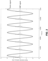
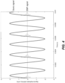
- Examples of overlaid sonic signals 106 and EMF signals 110 are shown in FIG. 2 through FIG. 6 . These figures show several graphs of a sonic signal (bolded line) and an EMF signal (unbolded line) on the same time axis.
- the sonic signal represented by the bolded line, in each graph shows an example sinusoidal signal of 40 kHz.
- the EMF signal represented by the unbolded line, shows various examples of signals that are based on a damped sinusoidal signal of 350 kHz.
- the amplitude of both signals is for illustrative purposes only. In some embodiments, the amplitude of the sonic signal is several times greater than the amplitude of the EMF signal.
- the positive amplitude of the sonic signal wave is taken to represent the compression portion of pressure waves, while the negative amplitude represents the expansion portion.
- the EMF signal is randomized, e.g., pulsed randomly (see, e.g., FIG. 2 ). As shown in FIG. 2 , the EMF signal is pulsed randomly, and is otherwise not correlated with the sonic signal. Such an EMF signal may be used in situations where resonance may occur and lead to ineffective EMF treatment, and, therefore, avoiding resonance is preferred. In such embodiments, a randomized EMF signal has a wide range of interactions with the sonic signal.
- the sonic signal and the EMF signal may be synchronized (see, e.g., FIG. 3 ).
- the sonic signal and the EMF signal are synchronized without any phase-shift.
- the EMF signal is pulsed at the same frequency (40 kHz) as the sonic signal, without any phase shift.
- the EMF signal and sonic signal may have similar fluid treatment effects (e.g., homogeneous nucleation of supersaturated salts in water and damage to microorganisms).
- Synergistic effects can be achieved by synchronizing the EMF signal and the sonic signals, where one of the signals is a higher harmonic (i.e., has a frequency that is n times the frequency of the other signal, where n is an integer) than the other signal.
- FIG. 4 and FIG. 5 demonstrate embodiments in which the EMF signal is pulsed at a lower harmonic frequency (20 kHz) and higher harmonic frequency (80 kHz), respectively, to the ultrasound signal.
- the EMF signal and sonic signal are correlated to achieve similar simultaneous effects as described in the case of FIG. 3 at certain cycles of the process.
- the sonic signal and the EMF signal have the same frequency, but are offset from one another by a phase-shift.
- the EMF signal is pulsed at the same frequency (40 kHz) as the sonic signal, but with a -90 degree phase shift from the sonic signal.
- starting the EMF signal prior to the compression portion of the sonic signal wave would allow for a few microseconds to disrupt hydration layers and cell walls or cell membranes prior to the impact of the compression wave, making the application of the sonic signal more effective at that time.
- the sonic signal and EMF signal frequencies, amplitudes, waveforms, phase-shifts, and decay rates are all factors that would be adjusted based on the fluids that are to be treated and the contaminants in the fluid to be treated. In some embodiments, one or more of these values will be adjusted as necessary by the controller 116 for the sonicator 108 and EMF generator 112, in response to a feedback loop.
- a feedback look may be built into a fluid treatment system 100.
- a sensor e.g., a microorganism detector upstream of the vessel 102, may observe an increase in the microorganism count upstream of the vessel 102 and transmit that reading to the controller 116.
- the controller 116 may respond in one of several ways, such as increasing the sonic signal amplitude, increasing the EMF signal amplitude, adjusting the frequency of the sonic signal, adjusting the frequency of the EMF signal, altering the phase-shift between the EMF signal and the sonic signal, or a combination thereof, so as to achieve a correlated signal set that can best impact microorganisms at those levels.
- a similar feedback loop utilizing a sensor, e.g., a contaminant detector can be utilized to achieve a correlated sonic and EMF signal set that can best impact the contaminants at those levels.
- signal processing of the sonic signal 106 and the EMF signal 110 e.g., residual signal effects, such as a Doppler shift, resonance, and harmonics generated within the vessel 102 may be used, by the controller 116 to monitor, evaluate, or adjust the treatment conditions.
- the controller 116 receives feedback from one or more sensors in real-time. In some embodiments, the sensor feedback is delayed or stored. In response to sensor feedback, the controller 116 may change a sonic signal feature, such as, frequency, intensity, and wave form; an EMF signal feature, such as, frequency, intensity, and wave form; and/or one or more synchronization parameters between the sonic and EMF signals, such as, frequency matching, harmonics, and phase shifting.
- a sonic signal feature such as, frequency, intensity, and wave form
- an EMF signal feature such as, frequency, intensity, and wave form
- one or more synchronization parameters between the sonic and EMF signals such as, frequency matching, harmonics, and phase shifting.
- a fluid treatment system comprises more than one sonicator.
- Each sonicator may produce a sonic signal that has at least one characteristic (e.g., frequency, waveform, amplitude, phase-shift, decay, and the like) that is different than a sonic signal from another sonicator.
- a sonicator produces a sonic signal that is substantially identical to a sonic signal from another sonicator in the system.
- a fluid treatment system comprises more than one EMF generator.
- Each EMF generator may Produce an EMF signal that has at least one characteristic (e.g., frequency, waveform, amplitude, phase-shift, decay, and the like) that is different than an EMF signal from, another EMF generator.
- an EMF generator produces an EMF signal that is substantially identical to an EMF signal from another EMF generator in the system.
- an EMF generator may be located in any location that allows the EMF signal to be conductively applied to the volume of fluid, for example upstream of the vessel 102 (i.e., upstream of the first port 104 ) or downstream of the vessel 102 (i.e., downstream of the second port 114 ).
- an. EMF signal propagates through a portion of a vessel, such that the EMF signal interacts with at least one sonic signal. In some embodiments, an EMF signal propagates through the entire vessel.
- the controller 116 may manage the sonic and/or EMF signal strength and frequency through the fluid treatment system in response to changes in upstream fluid conditions, downstream measurements of performance, or both.
- controller 116 is a standalone system that controls sonicator 108 and EMF generator 112.
- controller 116 is part of an integrated control system for a larger fluid treatment system.
- the controllers can communicate with one another using a direct communication connection (either wired or wireless) or via a common network.
- each controller can operate autonomously or can operate based on commands received from a central control station.
- the central control station is in the same location as the controllers.
- the central control station is located remotely.
- the common network may be any suitable network, such as an Ethernet network, a Modbus network, a CAN bus network, or some other appropriate communications network.
- a controller may include a network communication device that can be connected to an external network.
- the external network can be a LAN, WAN, cloud, Internet, or some other network, and can be wired and/or wireless.
- the protocol used can be any standard protocol, e.g., Ethernet, Modbus, CAN bus, TCP/IP, or any other appropriate protocol. Additionally, security and encryption technologies may be used.
- the controller can be used to control and/or monitor the fluid treatment process via a graphical user interface (GUI).
- GUI graphical user interface
- the GUI can include a display (e.g., an LCD, an LED display, etc.).
- the display is integrated into the controller, or a remote GUI is attached to the controller via appropriate hardware.
- a controller or a central control station can include a database for storing information, including, readings from sensors, flow rate data, power consumption data, and the like.
- a database can be stored in computer-readable media, on a separate device, or both.
- computer-readable media can also include the operating system and/or application software.
- a fluid treatment system such as the one illustrated in FIG. 1
- a fluid treatment system is a standalone fluid treatment unit.
- a fluid treatment system such as the one illustrated in FIG. 1 , functions as a component of a larger fluid treatment system.
- the treated fluid may undergo further treatments after exiting the vessel 102.
- Further fluid treatment processes that may he employed include advanced oxidation processes (AOP; e.g., ultra-violet radiation, ozone treatment, hydrogen peroxide treatment, etc.); filtration (e.g., micro-, nano-, and ultra-filtration); reverse osmosis; forward osmosis; applied pressure; applied vacuum; mechanical agitation; gas sparging and degassing; thermal treatments, (e.g., multi-stage flash distillation); membrane distillation; electrodialysis; biological reactors; anaerobic and aerobic biological treatment; chemical treatment systems; treatment with nucleation agents; treatment with absorbents; treatment with adsorbents; treatment with a biocide; flocculation; electroflocculation systems; electrocoagulation systems; electromagnetic radiation; ion exchange columns or systems; treatment with a reducing agent, such as zero-valent iron; treatment with a catalyst; treatment with a photocatalyst; or a combination thereof.
- AOP advanced oxidation processes
- filtration e
- an additional fluid treatment process comprises applying electromagnetic radiation; catalysts; photocatalysts; chemicals; biocides; nucleating agents; adsorbents; absorbents; thermal energy; biochemistry; or a combination thereof.
- a fluid treatment of the present disclosure may be combined with seawater/brackish water desalination, AWG, ocean thermal energy conversion (OTEC), tidal steam, energy generators, membrane bioreactors, or a combination thereof.
- the fluid to be treated includes drinking water, impaired water from agriculture, wastewater, ground water, surface water, grey water, seawater, produced water, flowback water, mining effluent, radiologically contaminated water, recycled water, industrial process water, cooling water, crude petroleum oil, processed petroleum, oil, a petroleum-based fuel, an organic solvent, a plant-based oil, a biofuel, a synthetic oil, a synthetic fuel, human physiological fluid, animal physiological fluid, or a combination thereof.
- the fluid to be treated is water.
- the fluid treatment systems may treat water for suitable purpose, such as, residential, industrial, indirect potable reuse, direct potable reuse (recycled water), ground water injection, commercial, food and beverage, hospitality, agricultural, mining, oil & gas, power, data centers, health-care, hospitals, nursing homes, pharmaceutical, government (e.g., military, federal, state, local, municipal, and foreign), security, space markets, emergency water use, fire-fighting use, or a combination thereof.
- suitable purpose such as, residential, industrial, indirect potable reuse, direct potable reuse (recycled water), ground water injection, commercial, food and beverage, hospitality, agricultural, mining, oil & gas, power, data centers, health-care, hospitals, nursing homes, pharmaceutical, government (e.g., military, federal, state, local, municipal, and foreign), security, space markets, emergency water use, fire-fighting use, or a combination thereof.
- the water to be treated is an impaired water stream that includes suspended solid materials.
- the impaired water stream may include surface water, groundwater, black streams, grey water streams, agricultural wastewater streams, livestock wastewater streams, sludge, flowback and produced water streams from mining, drilling, and (racking operations, and wastewater effluent.
- the water contains at least 1 % suspended solids, by mass. In some embodiments, the water contains at least 5% suspended solids, by mass.
- the fluid to be treated is an impaired water stream that includes suspended solid materials.
- the water stream may be treated with an adsorbent solid material with large uptake capacities for specific contaminants in the water, such as zeolites, metals, metal oxides, activated carbon, molecular sieves, polymers, resins, clay, and the like.
- the water stream containing the adsorbent may then be treated with sonic signals and EMF signals.
- the sonic signals may help to loosen the solid materials, release gaseous and aqueous contaminants from the solids, and improve the rate and adsorption of these contaminants onto the adsorbent material.
- the solids and adsorbent can then be recovered from the water through various processes, such as centrifugation and drying.
- various processes such as centrifugation and drying.
- the sonic signals and EMF signals to the water stream disrupts hydration layers on dissolved containments, reducing effective ion sizes and allowing the ions to enter smaller pores in the adsorbent material, and the signals prevent hydration layers from forming around ions as they enter the pores of the adsorbent material, enhancing the degree with which the ions can enter the pores of the adsorbent material.
- the fluid treatment systems described herein will produce separated water and solids that have lower levels of microorganisms (e.g., bacteria) than the starting impaired water stream, which may be, e.g., wastewater or animal waste effluent. After recovery, the solids may meet the standards for classification as Class A Biosolids by the Environmental Protection Agency (EPA).
- EPA Environmental Protection Agency
- additional treatment processes may also be used before, after, or during the application of EMF signals and sonic signals.
- Additional treatment processes include, for example, adding chemicals for pH adjustment; flocculants; oxidizing agents, such as ozone, hydrogen peroxide, and ultra-violet radiation; reducing agents, such as zero-valent iron; catalysts; and the like.
- Such additional treatment processes may enhance the rate, capacity, or both, of contaminant removal from the impaired water.
- the EMF signals and sonic signals are applied to the impaired water while one or more adsorbent materials (e.g., metals, metal oxides, zeolites, activated carbon, molecular sieves, polymers, resins, and clays) are present.
- adsorbent materials e.g., metals, metal oxides, zeolites, activated carbon, molecular sieves, polymers, resins, and clays
- the separated water then undergoes further treatment after the solids have been removed.
- the water is treated by applying sonic signals and EMF signals from another sonicator and EMF generator, respectively.
- the water is further treated with one or more additional treatment processes, such as filtration; reverse osmosis; forward osmosis; advanced oxidation treatments, such as ozone, hydrogen peroxide, and ultra-violet radiation; reducing agents, such as zero-valent iron; chemical treatment; electrochemical treatment; or a combination thereof.
- the fluid to be treated is water (e.g., surface water or ground water) contaminated with PFCs (e.g., perfluorinated alkyl halides, perfluorinated aryl halides, fluorchloroalkenes, perfluoroethers, perfluoroepoxides, pertluoroalcohols, pertluoroainines, perfluoroketones, perfluorocarboxylic acids, perfluoranitriles, perfluoroisonitriles, perfluorosulfonic acids, derivatives of perfluorosulfunic acids, and perfluorinated aryl borates).
- PFCs e.g., perfluorinated alkyl halides, perfluorinated aryl halides, fluorchloroalkenes, perfluoroethers, perfluoroepoxides, pertluoroalcohols, pertluoroainines
- PFCs including pertluoroalkyl substances (PFASs), perfluorooctane sulfonate (PFOS), and perfluorooctanoic acid (PFOA), contaminate sources of drinking water and, unless removed, persist in the environment indefinitely.
- PFASs pertluoroalkyl substances
- PFOS perfluorooctane sulfonate
- PFOA perfluorooctanoic acid
- adsorption by activated carbon is used to remove PFCs from water.
- activated carbon e.g., granular activated carbon or powdered activated carbon
- the uptake of the PFCs to the activated carbon is increased by at least about 8 times, as compared to the uptake of PFCs to the activated carbon without application of EMF signals and sonic signals.
- the uptake of the PFCs to the activated carbon is increased by about 8 times to 10 times, as compared to the uptake of PFCs to the activated carbon without application of EMF signals and sonic signals.
- additional treatment processes may also be used before, after, or during the application of EMF signals and sonic signals. Additional treatment processes include, for example, adding chemicals for pH adjustment; flocculants; oxidizing agents, such as ozone, hydrogen peroxide, and ultra-violet radiation; reducing agents, such as zero-valent iron; catalysts; and the like. Such additional treatment processes may enhance the rate, capacity, or both, of PFC removal from the impaired water.
- EMF signals and sonic signals are used in conjunction with zeolites or ion exchange columns that utilize, e.g., a polymer or a polymeric resin, to remove PFCs from water.
- the polymeric resins of ion exchange columns may be provided as, e.g., small beads that may have similar mass diffusion limitations for PFC uptake as activated carbon.
- mass transfer limitations are improved.
- the adsorption rate of the PFCs on the ion exchange columns, as well as the ion exchange columns' capacity may be increased significantly by combination exchange column treatment with EMF signals and sonic signals.
- sonic signals and EMF signals are used to improve methods of regenerating the polymer or polymer resin material.
- the polymers or polymer resins are traditionally regenerated using a solution (e.g., a weak acid), which is later disposed of, to remove the PFCs.
- the additional of sonic signals and conductive EMF signals may increase the regeneration speed and the proportion of PFCs removed from the polymer or polymer resin materials.
- the uptake of the PFCs to the ion exchange column is increased by at least about 8 times, as compared to the uptake of PFCs to the ion exchange column without application of EMF signals and sonic signals.
- the uptake of the PFCs to the ion exchange column is increased by about 8 times to 10 times, as compared to the uptake of PFCs to the ion exchange column without application of EMF signals and sonic signals.
- additional treatment processes may also be used before, after, or during the application of EMF signals and sonic signals to remove PFCs.
- Additional treatment processes include, for example, adding chemicals for pH adjustment; flocculants; oxidizing agents, such as ozone, hydrogen peroxide, and ultra-violet radiation; reducing agents, such as zero-valent iron; catalysts; and the like.
- Such additional treatment processes may enhance the rate, capacity, or both, of PFC removal, from the impaired water.
- FIG. 7 illustrates an embodiment of a larger fluid treatment system 700.
- a fluid is passed through a micro-filtration membrane 718 while being treated with an EMF signal from EMF generator 712 a .
- the fluid then travels to a vessel 702 in which the fluid is treated with an EMF signal >from EMF generator 712 b and a sonic signal from sonicator 708, as described above with regard to FIG. 1 .
- the sonicator 708 and the EMF generators 712 a , 712 b , 712 c may be controlled by a common controller 716.
- the controller 716 may independently control the sonicator 708 and each of the EMF generators 712, 712 b , 712 c .
- each of the sonicator 708 and EMF generators 712 a , 712 b , 712 c may be controlled by individual controllers.
- the controller 716 may manage the EMF signal strength and frequency in various locations (i.e., each of the EMF generators 712 a , 712 b , 712 c ) in of the fluid treatment system in response to changes in upstream fluid conditions, downstream measurements of performance, or both.
- the controller adjusts the EMF signal, the sonic signal, or both, in order to improve energy efficiency.
- the controller adjusts the EMF the sonic signal, or both, in order to adjust the quality of the resulting fluid.
- the fluid is then transferred to a solid separation unit 720, which may include one or more sedimentation steps, one or more filtration steps, one or more aeration steps, one or more dehydration steps, and the like.
- the water has less than 1 % by weight of suspended solids after being treated in the solid separation unit 720.
- the solids, after separation are subject to a sterilization step.
- the fluid may undergo a further sterilization step after the solids have been separated.
- a third. EMF generator 712 c is coupled to a conduit through which the fluid is transported from the solid separation unit 720 to an ion exchange and polishing tank 722. As described above, the third EMF generator 712 c applies an EMF signal to the fluid by a direct conductive path.
- the third EMF generator 712 c may produce an. EMF signal that has at least one characteristic (e.g., frequency, waveform, amplitude, phase-shift, decay, and the like) that is different than an EMF signal from another EMF generator.
- the third EMF generator 712 c produces an EMF signal that is substantially identical to an EMF signal from another EMF generator in the system 700.
- multiple EMF units 712 a , 712 b , 712 c may be used in a fluid treatment system without using a sonicator 708.
- the fluid is treated by removing one or more undesirable ionic contaminants by exchanging the undesirable ions with other less objectionable ions, as is understood by one of skill in the art.
- the controller 716 monitors the treatment process using one or more sensors, located throughout the system 700.
- sensors may include, for example, sensors to measure temperature, pressure, conductivity, pH, turbidity, total dissolved solids, total suspended solids, biological oxygen demand, chemical oxygen demand, flow rate, chemical composition, microorganism counts, and the like.
- fluid treatment, systems comprise an additional fluid treatment process, such as advanced oxidation processes (AOP; e.g., ultra-violet radiation, ozone treatment, hydrogen peroxide treatment, etc.); filtration (e.g., micro-, nano-, and ultra-filtration); reverse osmosis; forward osmosis; thermal treatments, (e.g., multi-stage flash distillation); membrane electrodialysis; biological reactors; anaerobic, and aerobic biological treatment; chemical treatment systems, treatment with nucleation agents; treatment with absorbents; treatment with adsorbents; treatment with a biocide; flocculation; electroflocculation systems; electrocoagulation systems; electromagnetic radiation; ion exchange columns or systems; treatment with a catalyst; treatment with a photocatalyst; or a combination thereof.
- AOP advanced oxidation processes
- filtration e.g., micro-, nano-, and ultra-filtration
- reverse osmosis e.g., micro-, nano-,
- an additional fluid treatment process comprises applying electromagnetic radiation, catalysts; photocatalysts; chemicals; biocides; nucleating agents; adsorbents; absorbents; thermal energy; biochemistry; or a combination thereof to the fluid.
- an additional fluid treatment process may be mineralization, chlorination, addition of United. States Food and Drug Administration (US-FDA) approved flavor and taste additives, filtration (including micro-, ultra-, and nano-filtration), softening, dechlorination, deammonification, organic scavenging, deiozinzation, reverse osmosis, forward osmosis, distillation, ultra-violet radiation, sterilization, or a combination thereof.
- US-FDA United. States Food and Drug Administration
- the fluid treatment system may be organized in any suitable order.
- one or more additional fluid treatment processes may occur upstream, downstream, in the same vessel, or a combination thereof, as the applied sonic signal and EMF signal.
- the fluid to be treated includes drinking water, impaired water from agriculture, wastewater, ground water, surface water, grey water, seawater, produced water, flowback water, mining effluent, radiologically contaminated water, recycled water, industrial process water, cooling water, crude petroleum oil, processed petroleum, oil, a petroleum-based fuel, an organic solvent, a plant-based oil, a biofuel, a synthetic oil, a synthetic fuel, human physiological fluid, animal physiological fluid, or a combination thereof.
- the fluid to be treated is water.
- the fluid treatment systems may treat water for suitable purpose, such as, residential, industrial, indirect potable reuse, direct potable reuse (recycled water), ground water injection, commercial, food & beverage, hospitality, agricultural, mining, oil & gas, power, data centers, health-care, hospitals, nursing homes, pharmaceutical, government (e.g., military, federal, state, local, municipal, and foreign), security, space markets, emergency water use, fire-fighting use, or a combination thereof.
- suitable purpose such as, residential, industrial, indirect potable reuse, direct potable reuse (recycled water), ground water injection, commercial, food & beverage, hospitality, agricultural, mining, oil & gas, power, data centers, health-care, hospitals, nursing homes, pharmaceutical, government (e.g., military, federal, state, local, municipal, and foreign), security, space markets, emergency water use, fire-fighting use, or a combination thereof.
- the fluid to be treated is drinking water.
- the water produced may meet purity standards from federal, state, and local laws for one or more of potable water, drinking water, bottled water, mineral water, high-performance water (pH>7.0), purified water (as defined by the US Pharmacopeia (USP), water for injection (USP), water for special pharmaceutical purposes (LISP), water for hemodialysis (LISP), sterile purified water (USP), non-potable water, secondary-treated water, tertiary-treated water, and recycled/reclaimed water.
- the water produced may meet purity standards from federal, state, and local laws for one or more of groundwater reinjection, surface water injection, indirect potable reuse, direct potable reuse, aquifer recharge, and aquifer storage and recovery.
- a fluid treatment system is coupled to an Atmospheric Water Generation (AWG) unit.
- AWG units draw in moisture-laden air and pass it through coolers and condenser systems to condense the water vapor into liquid water.
- the collected water generally has far less contamination as compared to surface or groundwater sources.
- an AWG unit comprises one or more air filters that further decrease the levels of contaminants in the extracted water. Additionally, because AWG units can be operated without the need for water infrastructure, AWG units are ideal for providing water during emergency situations or where surface or groundwater is scarce.
- a fluid treatment system of the present disclosure would increase the amount of power needed by a relatively small amount as compared to the amount of power required to operate an AWG unit.
- an AWG unit when combined with a fluid treatment system of the present disclosure, provides a source of water that has not been chemically treated.
- AWG units may include additional treatment systems that are used in combination with a fluid treatment system of the present disclosure (i.e., a system comprising a sonic energy generator and an EMF generator) to treat the collected water.
- the controller of the fluid treatment system may adjust the treatment conditions based on readings from one or more sensors.
- sensors may include, for example, a humidity sensor, a temperature sensor, a pressure sensor, a wind speed sensor, or a combination thereof.
- a control unit of the AWG unit may act as a controller of the fluid treatment system.
- a controller of the fluid treatment system may be integrated with a control unit of the AWG unit.
- the fluid treatment system is active while the AWG unit is operating. In sortie embodiments, the fluid treatment system is active while the AWG unit is not operating.
- Embodiments of the disclosure further comprise platforms that comprise one or more fluid treatment systems comprising a sonic energy generator and an EMF generator, as well as a variety of systems and subsystems (e.g., energy generation systems, energy storage systems, recycling systems, and the like).
- the various systems and subsystems may have individual control systems, may share a centralized control system, or both.
- the control systems may be structured in a system-of systems approach that uses data collection, aggregation, and analysis for optimizing the performance of each system of the platform in response to internal conditions, external conditions, or both.
- the control system may be used to monitor and control the entire platform, including, for example, activating or deactivating an individual unit in response to a change in, local weather.
- the platforms of the disclosure are connected to one or more other devices via a network.
- a control system of a platform of the disclosure is connected to one or more other devices via a network.
- the platform is connected to the Internet of Things (IoT).
- IoT Internet of Things
- a control system of a platform of the disclosure is connected to the IoT.
- data may be communicated using IoT protocols, such as Infrastructure (e.g., 6LowPAN, IPv4/IPv6, and RPL), Identification (e.g., EPC, uCode, IPv6, and URIs), Communications/Transport (e.g., Wifi, Bluetooth, and LPWAN), Discovery (e.g., Physical Web, niDNS, and DNS-SD), Data Protocols (e.g., MQTT, CORP, AMQP, Websocket, and Node), Device Management (e.g., TR-069 and OMA-DM), Semantic (e.g., JSON-LD and Web Thing Model), Multi-layer Frameworks, or a combination thereof.
- IoT protocols such as Infrastructure (e.g., 6LowPAN, IPv4/IPv6, and RPL), Identification (e.g., EPC, uCode, IPv6, and URIs), Communications/Transport (e.g., Wifi, Bluetooth, and LPWAN
- An IoT-enabled control system may be in communication with an IoT system that tracks weather patterns at a larger scale (e.g., regional, state, national, etc.).
- a control system, or a device connected to the control system via the network uses data provided by the IoT system to model predicted weather conditions.
- a control system may use data analysis tools, methods, and control strategies that include, for example, real-time model analysis; predictive modeling and control; artificial intelligence systems including, neural networks, fuzzy logic systems, genetic algorithms, and expert systems; software agents; knowledge management (KM) systems for data mining, cloud computing, parallel and distributed computing utilized in IoT for the fields of, e.g., Building Internet of Things (BloT), smart cities, infrastructure and utilities, healthcare systems, insurance industry, and manufacturing; or a combination thereof.
- BloT Building Internet of Things
- a platform of the disclosure operates as a node within a nodal network of other water, power, and data generators and distributors, which includes data sharing throughout the nodal network to achieve optimum intra-platform and inter-platform performance for the entire nodal network capable of fault tolerant operations, addressing redundancy, resiliency, and stability of system operations during nominal, optimal, and emergency use.
- the platforms of the, disclosure may include, one or more sensors that provide data to local control systems, as well as one or more networked devices. Such data may be used by the control system to optimize the performance of one or more systems.
- a platform that comprises a plurality of AWG units may include a humidity sensor, or other sensor providing an indication of water vapor in the air, that provides readings to the control system.
- the humidity sensor may record an increase in humidity that causes the control system to activate one or more AWG units.
- Platforms of the disclosure may comprise one or more systems that are configured to utilize a variety of components that are suited to the specific geographic region where the system is located.
- a platform located near an ocean or salt-containing water source may include both AWG units, as well as reverse osmosis units and associated filtration systems to generate additional clean water from the ocean or salt-containing water source, and energy generation units to provide or offset electricity for the AWG units, osmosis units, and other components the platform.
- the location of the system and the local and/or regional weather conditions e.g., temperature, relative humidity, etc.
- the control system may be accounted for in real-time by the control system to respond to environmental changes, to negotiate with external factors (such as the BloT and IoT), or both.
- a platform located near an ocean or salt-containing water source may also include temperature and humidity sensors as part of the control system.
- the readings from these sensors, through the control system could be used to predict how much water the AWG units could produce, and to modulate how much water should be produced by the osmosis systems to augment the AWG water production, so as to maintain a continuous water production rate from the platform.
- This mode represents a type of on-demand water load-balancing.
- the platform could be built with deployable AWG units, and have a control system that communicates with external weather and water monitoring databases to detect events (e.g., natural or manmade emergencies) related to biosafety (e.g., hurricanes and flooding) and biosecurity (e.g., inadvertent or purposeful contamination of the water supply with toxic materials) of the water supply. If such an event is detected, the control system may begin procedures to deploy one or more AWG units. The controller would allow the AWG units to be disconnected from the platform and rapidly deployed to provide fresh water to affected persons during these emergencies.
- events e.g., natural or manmade emergencies
- biosafety e.g., hurricanes and flooding
- biosecurity e.g., inadvertent or purposeful contamination of the water supply with toxic materials
- a platform of the disclosure is used to bring on new technologies alongside established technologies to provide for rapid prototyping and certification of new technology to meet the same federal, state, and local laws and regulations that the established platform technology must meet.
- the platforms of the disclosure may include, or be located in close proximity to, one or more utilities. These utilities may be used to support the platform, provide access to the utilities to surrounding communities, support larger utilities, or a combination thereof.
- a platform includes a data/communications system. In some embodiments, a platform is located in close proximity to a data/communications system.
- a platform includes a water treatment facility. In some embodiments, a platform is located in close proximity to a water treatment facility. In some such embodiments, the water treatment facility utilizes a surface water source.
- a platform includes a power generation system or a power storage system (e.g. a solar cell system, a hydroelectric system, etc.). In some embodiments, a platform is located in close proximity to a power generation system or a power storage system.
- the power generation system or power storage system may be comprised of renewable components, non-renewable components, or a combination thereof. Suitable power generation or power storage systems include power plants based on fossil fuels (e.g., natural gas, coal, and oil), nuclear energy generated from subatomic particle reactions and collisions, renewable fuels (e.g., biofuels), or sustainable fuel stock (e.g., biomass and municipal solid waste/refuge-derived fuels).
- fossil fuels e.g., natural gas, coal, and oil
- renewable fuels e.g., biofuels
- sustainable fuel stock e.g., biomass and municipal solid waste/refuge-derived fuels.
- Additional power generation or power storage systems include renewable power systems, such as solar and wind farms; geothermal and hydroelectric systems; fuel cells; flow cells; solid-state, salt-based, and liquid battery systems; capacitors and ultra-capacitors; and thermal energy storage devices.
- the platform is connected to conventional grid power. In other embodiments, the platform is not connected to the conventional power grid.
- a platform of the present disclosure may comprise a plurality of AWG units and one or more fluid treatment systems.
- the plurality of AWG units may all be of the same type (e-g, manufacturer, capacity, etc.). In other embodiments, the plurality of AWG units comprises AWG units of more than, one type.
- one or more AWG units have a first setting and a second setting, the first setting having a higher extraction efficiency and a higher energy consumption compared to the second setting, and the second setting having a lower extraction efficiency and a lower energy consumption compared to the first setting.
- the first setting produces at least 5% more water at the same temperature and humidity conditions than the second setting. In some embodiments, the first setting uses at least 5% more energy at the same temperature and humidity conditions than the second setting.
- an AWG unit may be operated in the first setting or the second setting based at least on data regarding geography, climate, weather, water demands or available supply, power demands or available supply, or a combination thereof. Such data may be received in real-time from a sensor, an external source, etc. or produced by predictive modeling. Sensors that may be of use include humidity sensor, a temperature sensor, a pressure sensor, a wind speed sensor, or a combination thereof.
- the fluid treatment systems may be located in any suitable location, e.g., coupled to a co-located water storage tank, coupled to conduits that transfer the water from individual AWG units to a co-located water storage tank, coupled to a water storage tank for an individual AWG unit, and the like.
- Each AWG unit may have an autonomous controller (e.g., an integrated controller for the AWG unit and the fluid treatment system) that may activate and deactivate the AWG unit without consideration of other AWG units.
- the autonomous controller may activate or deactivate the AWG unit in order to maximize the performance of the AWG unit based on, for example, relative humidity and temperature of the surrounding air.
- more than one AWG units is controlled by a control system that activates and deactivates individual AWG units.
- the control system may change an AWG unit from a first setting to a second setting, or from a second setting to a first setting based at least on data regarding geography, climate, weather, water demands or available supply, power demands or available supply, or a combination thereof.
- the control system may be used to maximize the energy efficiency and water recovery of the plurality of AWG units as temperature and humidity change with time.
- the control system is used to maximize the water production rates, electrical and water recovery efficiencies while minimizing power usage and energy and water production costs.
- control system may be used to control the fluid treatment system of the present disclosure, including at least one sonic energy generator and at least one EMF generator, as well as any additional treatment systems.
- a platform of the present disclosure may serve as a source for water and power in an emergency (e.g., for disaster response) or for locations in which it is preferable to not utilize conventional water or power.
- platforms of the present disclosure may provide water resiliency (i.e., the ability to resist, absorb, accommodate to, and/or recover from the effects of a hazard in a timely and efficient manner) and water security.
- Such a platform may'be configured as a satellite emergency response system for water treatment, power, and data communications to be deployed for emergency response and use.
- a platform is configured to meet military-grade command, control, communication and computer (C4) operations for US Department of Defense (DoD) and Department of Homeland Security (DHS), as well as International Security Organizations (ISO).
- C4 military-grade command, control, communication and computer
- DoD US Department of Defense
- DHS Department of Homeland Security
- ISO International Security Organizations
- the platform may be IoT enabled with necessary protocols to operate within DoD, DHS, and ISO specifications.
- one or more subsystems of the platform are not locationally fixed, and may be moved to another location in an expeditionary, emergency, and/or remote mode.
- each sub-system may be operated in a temporary, intermittent, and/or permanent scheme.
- the platform operates as a trading desk for water, power, and data commodities trading (i.e., transactions for buying and selling of water, power, and associated data).
- the water, power, and associated data may be sold for its highest and best use, or for maximum value based on the availability of local water and power usage.
- the water and power generated are sold to customers when these commodities are not readily available from local municipalities or other local sources, if it is not cost, effective to purchase the commodities from, such sources, or both.
- Such trading desks can be used as a virtual support of local future markets, suited for diurnal (e.g., daytime, when the sun is available and at night when it is not that effects variables such as incident light, heat, temperature, relative humidity, pressure, wind speeds, etc.) and seasonal conditions, as well as for local spot market sales of water, power, and related data.
- the platform may be arranged as an optimal network of systems to generate, store, negotiate sales of, and distribute water, power, and related data.
- the optimal network of systems may also serve as a local resource to further communicate and negotiate specific outcomes with the loT.
- the platform (1) collects and aggregates data from one or more internal or external data sources, including one or more elements selected from the group consisting of: historical data; past and current operating, conditions of the platform's systems and sub-systems; current environmental and weather conditions; external databases and information sources such as National Oceanic and Atmospheric Administration (NOVA), Geographic Information Systems (GIS), and United State Geological Survey (USGS) databases; global, federal, state, and local databases and information sources such as DHS, EPA, and the United States Departments of Ecology and Energy; signaling and events from external water, power, and data generators and distribution systems; past and current performance, efficiencies, and quality of water, power, and data produced by the platform; past, current, and projected external conditions; model estimates and predictions; and past, current, and future supply and demand for water, power, and data; (2) defines a set of candidate operating parameters for the platform that defines the source(s) of water, power, and data; the target quantity and quality of water, power, and data to be generated; the control of the distribution
- the platform may be used to support a system of water use efficiency.
- the optimization of water, power, and data generation may be used to support such a system for water use efficiency.
- Such embodiments include a method in which water produced by a platform is valued proportional to the volume of potable (primary), secondary, and tertiary water that is generated and made available for distribution.
- a system or subsystem of the platform analyzes and negotiates for water available for immediate use and/or generated water based on immediate, mid-term, and long-term demand based on the most efficient source of water to parties (e.g., wholesalers, retailers and end-users) as potable, secondary; and tertiary water sources.
- a system or subsystem of the platform determines and transmits a signal to another platform or an external device to recommend water use reduction and conservation, beneficial uses of water, water recycling and reuse, and accessing water of alternative water sources.
- a system or subsystem of the platform determines and transmits a suggested setting for one or more AWG units to increase water production, reduce power usage, etc.
- embodiments include optimization of water, power, and data generation is used to support a system for water use efficiency, which includes; (1) methods, by which water producers could value, or be allocated the agreed upon value, of water proportional to the volume of potable (primary), secondary, and tertiary water they generate and make available for distribution; (2) methods by which a platform of the disclosure can analyze and negotiate between water available for immediate use and/or generate water based upon the immediate, mid-term, and long-term demand based on the most efficient method or source of water to wholesalers, retailers, and end-users as potable, secondary, and tertiary water sources; and/or (3) methods to determine and transmit appropriate signals and suggested modes to a platform of the disclosure and/or a network of platforms to recommend water use reduction and conservation, beneficial uses of water, water recycling and reuse, and accessing water of alternative water sources.
- Platforms of the disclosure may incorporate an environmental management system (EMS) framework that defines a set of processes and practices for reducing the environmental impact of the platform, and for meeting federal, state, and local laws and regulations for environmental impact and industry-established standards (such as ISO 14001), by integrating the data, and communication systems on the platform with additional internal and external data, software, and systems.
- EMS environmental management system
- the EMS includes environmental compliance, health and safety compliance; energy efficiency; energy conservation; water conservation; environmental conservation; environmental sustainability; waste reduction; hazardous materials and waste management systems; utility management systems; planning, programming, budgeting and execution systems; workflow management systems; training and work practices documentation and systems; maintenance and support systems; risk assessment and management systems; emergency preparedness and response systems; physical and electronic security software and systems; EMS data tracking and monitoring software and systems; EMS data analysis software and systems; EMS Big Data and data analytics software and systems; EMS reporting software and systems; EMS interface software and systems; EMS auditing software and systems; compliance assessment and reporting software and systems; or a combination thereof.
- the EMS descriptive and prescriptive analysis is a result of the platform's EMS data analytics, auditing, and compliance assessment provides the necessary documentation to demonstrate lowest risk and warrant lower insurance premiums.
- the EMS includes water management plan (WMP) to outline descriptive and prescriptive steps and control measures to assure the microbiological quality of water (such as detection of E. Coli and Legionella) produced by the platform to meet federal, state, and local water quality requirements and industry-established standards (such as ASHRAE 188).
- WMP water management plan
- the EMS and the platform(s) may be used to rapidly on-board and update all stakeholders to the physical platform or network configuration and layout (such as process flow diagrams (PFD), process instrumentation drawing (P&ID) and water and power distribution systems), performance metrics, preventative verification, control measures, validation, and associated documentation, utility and commodity consequences to financial outcomes (such as financial statements and strategies as they relate to business operation and the trading desk operations described above) of all processes as part of a training methodology to provide platform-relevant skills and information to appropriate stakeholders.
- the platform-relevant operation and maintenance skills include, e.g., water treatment, water generation, energy generation, energy efficiency, energy conservation, environmental sustainability, environmental, conservation, or a combination thereof.
- Platforms that comprise a plurality of AWG units that is collectively capable of producing at least 10,000 gallons per day are considered large scale AWG platforms.
- such platforms comprise more than one type of AWG unit.
- the types of AWG units may have varying efficiency based on the relative humidity.
- the first type produces at least 5% more water at the optimal temperature and humidity conditions than the second type.
- the electrical efficiency of the first type is at least 5% different at the optimal temperature and humidity conditions than the second type.
- a control system of the large scale AWG platform may activate and deactivate one or more AWG units of a particular type depending on the conditions (e.g., temperature, humidity, wind speed, wind direction, etc.) in order to maximize energy efficiency and water recovery of the large scale AWG platform.
- one or more AWG units of a particular type are activated or deactivated based on a relative humidity (RH) threshold value (i.e., an RH trigger value).
- RH relative humidity
- the RH trigger value may be based on the energy efficiency of an AWG unit at a particular RH value.
- the RH trigger value can be optimized to improve electrical efficiency within the large scale AWG platform.
- Activating AWG units that are electrically inefficient at a low RH, but very electrically efficient at a high RH, at too low of an RH trigger value may lead to poor overall electrical efficiency of the platform.
- activating the same AWG units at too high of an RH trigger value may significantly lower the overall efficiency of the platform by failing to utilize the improved individual efficiency of the AWG units at high humidity.
- the analysis of the optimum RH trigger value would be different for each large scale AWG platform, and would vary based on location, weather patterns, end-user requirements, and the like. Such an analysis would be platform specific and may be based on performance curves for specific types of AWG units, historical weather data from the location, and the like. Similarly, the analysis to determine the optimum ratio of types of AWG units that would provide optimum electrical efficiency for a given RH trigger value, will take into consideration their respective capital and operating costs. An example of such an analysis is provided as Example 1.
- the current weather in a given location may impact the ratio and number of AWG units of varying types that are activated or deactivated. For example, if a pressure front is forecasted to move over the location, and precipitation is expected, which is a sign of high humidity, then the control system may activate a type of AWG units earlier, or more AWG units of that type than would otherwise be activated, to increase water recovery, electrical efficiency, or both.
- a large scale AWG platform is operated to optimize the water production efficiency, power production efficiency, and costs for each AWG unit and for the large scale AWG platform as a whole.
- a large scale AWG platform is also operated to optimize the water production efficiency, power production efficiency, and costs for a plurality of large scale AWG platforms.
- the manner of operation e.g., number of activated AWG units, ratio of AWG units of varying types that are activated, etc.
- Such manners of operation may create an ad hoc network of satellite utility platform installations that interacts, supports, sand augments traditional utility installations.
- the manner of operation of the plurality of large scale AWG platforms is determined by (1) collecting and aggregating data from one or more internal or external data sources, e.g., historical data; past and current operating conditions of the platform's systems and sub-systems; past and current performance; efficiencies, and quality of water, power, and data produced by the platforms within, past, current, and projected external conditions; model estimates and predictions; and current arid future supply and demand for water, power, and data; (2) defining a set of candidate operating parameters for each platform within the network that defines the source(s) of water, power and data, the target quantity and quality of water, power, and data to be generated, and other associated operating conditions for the platform; (3) using an optimization function to evaluate the candidate operating parameters against the aggregated data; (4) adjusting or refining the candidate operating parameters to minimize or maximize the optimization function through an optimization search algorithm, with consideration of federal, state, or local laws and regulations, or system or sub-system limitations; and (5) applying the selected operating parameters to the platforms on the network.
- internal or external data sources
- a large scale AWG platform is flexible and can access sources of water found in the atmosphere, in or on land, in the ocean, or in other brackish bodies of water.
- a location may have access to an impaired water source from a well, aquifer, lake, reservoir, or municipal treatment plant that is not operating to public drinking standards, is unreliable, or has tainted water from the distribution infrastructure.
- a large scale AWG platform could be installed in this location that could address the impaired available sources via the fluid treatment using sonic signals and. EMF signals of the present disclosure, in combination with a plurality of AWG units to extract additional water from the atmosphere for potable and non-potable use.
- the large scale AWG platform could provide an immediate source of clean water from atmosphere via the plurality of AWG units, while the water treatment system processes the water collected from the other sources.
- a large scale AWG platform is located near a body of water, water treatment, power production, or a combination thereof.
- a large scale AWG platform may be situated near an existing natural or man-made body of water.
- the AWG units are located principally downwind of an existing water source (e.g., ocean, sea, lake, or river).
- an AWG unit is located within one mile of a body of water.
- the large scale AWG platform site may include man-made open water pools, such as retention ponds, that are located so that the AWG units of the platform sit downwind from the water sources.
- the wind passing over the bodies of water may accumulate additional moisture drawn into the air by natural evaporation prior to reaching the AWG units, and increases the moisture that may be collected by the large scale AWG platform.
- the water source(s) may be impure, such as surface water, including fresh and sea water, rain water ponds, or wastewater tanks.
- the evaporated moisture will be primarily clean water, with the contaminants being left behind.
- The. AWG units and the fluid treatment systems of the present disclosure provide a further level of protection in the produced water purity.
- a large scale AWG platform may be located near water sources that are either a part of, or combined with, another water treatment system, such as wastewater treatment plants (e.g., municipal wastewater treatment plants, reclaimed water treatment plants, etc.), brackish/seawater desalination plants, OTEC, tidal steam energy generators, geothermal systems, hydroelectric plants, and remediation ponds for drilling, mining, and hydraulic fracturing water treatment.
- wastewater treatment plants e.g., municipal wastewater treatment plants, reclaimed water treatment plants, etc.
- OTEC e.g., brackish/seawater desalination plants
- tidal steam energy generators e.g., geothermal systems
- hydroelectric plants e.g., tidal steam energy generators
- remediation ponds for drilling, mining, and hydraulic fracturing water treatment.
- a large scale AWG platform is co-located with a power plant.
- the large scale AWG platform can be designed to work within the specifications of the existing power supply, and use the open water sources in the water treatment site to gain additional moisture from which clean water may be extracted.
- the large scale AWG platform is used to augment water production from the co-located water treatment or production facility.
- the co-located system may be a desalination plant with an optional power generation, and the large, scale AWG platform may be used to further treat waste water rejected by the desalination plant.
- the large scale AWG platform uses the co-located water treatment or production facility to provide additional water to reach a minimum water production rate when the AWG units or other water treatment systems on the platform temporarily cannot meet the minimum, production rate.
- a well-designed configuration or physical arrangement of the AWG units in a large scale AWG platform would be one that assures good air distribution between and around the units, so that all units would be drawing from air with substantially the same moisture content.
- the AWG units of a large scale AWG platform may be installed in a three-dimensional pattern in an open-air framework. Such an arrangement may increase the amount of moisture captured from the air by extracting water from air that is further from the ground. Further, such an arrangement may improve efficiency and reduce the land footprint or area required, for example, a multi-storied open structure, similar to an open-air parking garage, with sufficient clearance between each story for the AWG units, could be used.
- AWG units are positioned atop existing structures. Accordingly, in some embodiments, the arrangement of the AWG units of a large scale AWG platform includes the elevation and the geographic position of each unit.
- Evaporative processes may also be utilized in a "bio-sphere" or closed environment.
- a large scale AWG platform design may be more effective when the motion of the air is accelerated through the site.
- Faster air motion may increase rates of mass transport and evaporation across an open surface, which increases the moisture concentration, i.e., humidity, of the air.
- the AWG units of a large scale AWG platform are, arranged such that each AWG unit is drawing from air that has a temperature and moisture content that is within +/-2% of the air's temperature and moisture content upwind of the large scale AWG platform, based on historical and model averages of the weather behavior around the site.
- the configuration of the AWG units of a large scale AWG platform is mathematical modeled to determine the optimal placement of each AWG unit such that the inlet air temperature and moisture content is normalized for each AWG unit, on average.
- additional fixtures designed to direct and accelerate air flow are arranged in locations adjacent to AWG units.
- the additional fixtures may be arranged upwind of the AWG units.
- Such additional fixtures may be arranged in order to increase the moisture content of the air surrounding the AWG units.
- Any suitable additional fixtures may be used, including, passive units (e.g., walls, columns, blades, baffles, grates or other hardened structures) or powered units (e.g., motorized fans or venturi effect-based fans).
- the units may be controlled to adjust the air speed over the AWG unit.
- These fixtures may be mounted on bases that rotate with the prevailing wind direction.
- the fixtures are mounted on bases that are controlled.
- the fixtures may be turned, either automatically or manually, with changes in the wind direction in order to increase the air velocity and mixing at or near the AWG unit location.
- an additional structure such as a windmill or a wind turbine, is located downwind of the AWG units in order to recover momentum energy from vented air from the AWG units.
- the arrangement of AWG units in a large scale AWG platform are chosen so as to not disrupt atmospheric weather conditions via dehumidification of downwind locations.
- AWG units located downwind of other AWG units may have lower performance, as the air may have a lower moisture content.
- the location of a large scale AWG platform relative to another large scale AWG platform may impact the efficiency and capacity for each platform.
- the arrangement of AWG units in a large scale AWG platform is chosen so as not to be adversely impacted by, a second large scale AWG platform that is located upwind.
- the location of an AWG unit relative to natural or man-made features, the configuration and arrangement of an AWG unit within a large scale AWG platform, and the placement of a large scale AWG platform relative to other large-scale AWG platforms, are selected to optimize the overall water production capacity and energy efficiency of the large scale AWG platform.
- NLA Natural Local Atmosphere
- the atmospheric ceiling is at least 3,000 meters. In some embodiments, the atmospheric ceiling is from 100 meters to 10,000 meters. In some embodiments, the atmospheric ceiling is from 1,000 meters to 5,000 meters.
- the air in a NLA will have the maximum moisture content that is available to be extracted by a large scale AWG platform.
- the production rate of an AWG unit will be highest when operating in a NLA.
- AWG units of a large scale AWG platform are arranged to maximize the moisture content of the ambient air and production rate for a given location and AWG unit efficiency given the local weather patterns.
- two or more large scale AWG platforms are arranged to maximize the moisture content of the ambient air and production rate for a given location and AWG unit efficiency given the local weather patterns.
- the separation of each large scale AWG platform is at least one mile.
- a large scale AWG platform is placed at a site located between the latitudes of North 35° to South 35° (i.e., in the tropics and subtropics).
- a large scale AWG platform is placed at a site located between the latitudes of North 23.5° and 35° or South 23.5° and 35° (i.e., in the subtropics).
- the optimal arrangement of one, or more large scale AWG platforms may be calculated in any suitable manner.
- an initial placement for the one or more large scale AWG platforms is chosen; mathematical model(s) are used to determine the NLA and the large scale AWG atmosphere (LSAWGA) conditions for each large scale AWG platform; and this information is compared to additional data sources to determine if the proposed locations are acceptable. If not, the placements may be refined.
- the models used to determine are used to determine.
- NLA and LSAWGA may incorporate temperature, pressure, humidity, wind speed and wind direction, precipitation, cloud cover, solar radiation, air composition, pollution, time of day, time of year, geographic coordinates, land elevation data, land use data, vegetation coverage, urban area coverage (cities, building sizes and types), soil types, the arrangement Large-Scale AWG platform, or a combination thereof.
- the calculation of NLA and LSAWGA incorporates historical and predicted weather and climate data; mathematic weather prediction models; geographic data sources such as GIS or ARCInfo; water source data such as USGS data; and/or local water, power, and data utility capacity and generation/distribution.
- N number of large scale AWG platforms, where N ⁇ 1
- the optimal arrangement is to place the one or more large scale AWG platforms in the smallest possible area without changing the NLA.
- the one or more large scale AWG platforms would be located in the smallest geographic area that enables the optimum water to be extracted from the atmosphere to a maximum elevation (z max ) from all large scale AWG platforms.
- the minimum distance, (x, y) variables, that a large scale AWG platform can be placed in proximity to another large scale AWG platform without changing the NLA will be determined.
- the planned placement of each large scale AWG platform is defined by coordinates (x 1 , y 1 ), (x 2 , y 2 ), ... (x N , y N ).
- the NLA for the region is determined based on historical weather patterns, and includes atmospheric properties such as moisture M (kg/kg), defined at each point within the region. For example, M NLA (x 1 , y 1 ) represents the moisture content of the NLA at the planned site to z max in elevation for the first large scale AWG platform.
- LSAWGA 1 represents the predicted atmosphere conditions with the addition of the first large scale AWG platform
- LSAWGA 2 represents the predicted atmosphere conditions with the addition of the second large scale AWG platform (in addition to the first large scale AWG platform), and so forth.
- M LSAWGA1
- the placement of the large scale AWG platform that would maintain the NLA may be determined. In some embodiments, the comparison between NLA and.
- LSAWGA is made using an objective function, which may be resolved spatially and/or temporally, applied to NLA and LSAWGA that includes the evaluation of one or more variables (including their average values, their standard deviations, and/or their variables) over at least some of the volume within the region, and/or over one or more time segments.
- objective function which may be resolved spatially and/or temporally, applied to NLA and LSAWGA that includes the evaluation of one or more variables (including their average values, their standard deviations, and/or their variables) over at least some of the volume within the region, and/or over one or more time segments.
- variables that may be incorporated into the objective function include temperature; pressure; humidity; wind speed; wind direction; turbulence measurements; precipitation; weather fronts; weather storm systems (such as tornados, hurricanes, and typhoons); cloud cover; surface parameterization parameters; buoyancy stability; inertial stability; Monin-Obukhov length; bulk Richardson number; gradient Richardson number; planetary boundary layer height; momentum surface roughness length; heat surface roughness length; moisture surface roughness length; surface fluxes for momentum, latent heat, and moisture; hydrology parameters; water table levels; surface water locations, capacity, and current levels; groundwater levels; aquifer capacities and current levels; surface water quality; groundwater quality; ocean currents; ocean tides; air-to-sea interface parameters; water demand requirements; electrical demand requirements; water usage data; power usage data; electricity costs; water utility costs; land elevation; land use; land costs; capital equipment costs; operating and maintenance costs; population; population growth; short- and long-term climate forecasting, long-term water availability; and
- Such methods of arranging the AWG units of a large scale AWG platform may be used to influence the local weather or to collect water from the air, as a type of atmospheric water harvesting.
- a large scale AWG platform may be used to extract layers of water, held in water-laden air, as an atmospheric resource.
- a large scale AWG platform may be used to direct water-laden air to a second large scale AWG platform.
- a large scale AWG platform may be located in order to create local weather lanes.
- a large scale AWG platform may be arranged to create a local weather pattern berm.
- Large scale AWG platforms may be arranged and used to deliberately influence weather patterns (e.g., short-term weather patterns) into a beneficial use, such as by removing moisture from the air to help reduce the instability of the air as a type of weather buffer, or by using other nearby geographic features to promote a general trend fore wind flow direction.
- weather patterns e.g., short-term weather patterns
- the effects of a large scale AWG platform on regional weather patterns have been modeled, and the results are described in Example 2.
- a large scale AWG platform includes a plurality of small AWG units and a plurality of large AWG units.
- the small AWG units are efficient at high humidity levels (e.g., 80% or better relative humidity), but are vow inefficient at low humidity levels (e.g., below 50% relative humidity).
- the large AWG units are not as efficient at high humidity as the small units, but can generate appreciable amounts of water at a relative humidity lower than 50%.
- the control system may operate the large units continuously in order to base-load the generation of water, while activating the small units when the humidity exceeds 50% to gain the advantage of their efficiency at this point. Depending on several factors (e.g., power costs, etc.), the control system may activate the small units when the humidity exceeds 80%.
- the control system is able to maximize the generation of water while minimizing the energy required, as compared to using strictly one type of AWG unit or the other.
- the reported performance of two commercial AWG units was used to model a large scale AWG platform.
- the large. AWG unit used in the model is optimized to generate 2,500 gal/day of water, at 80% relative humidity (RH) and can readily handle low humidity.
- the small AWG is optimized to generate 1-250 gal/day at 80% RH with good electrical efficiency, but does not perform well at humidity less than 50%.
- the humidity is the largest driver for the AWG unit performance.
- temperature may play a significant role in the performance for an AWG unit, for purposes of this example we assume that the temperature effects are equivalent for both units and do not account for them at this time.
- the effect on humidity for water production and energy efficiency for the two types of AWG units are shown in FIG. 8 and FIG. 9 , respectively.
- RH data from central Texas over the course of three days is considered. This data was taken from the National Weather Service during a period of relatively calm weather that is representative for that time of the year.
- the RH data as a function of hour of the day is shown in FIG. 10 .
- the humidity pattern shown in FIG. 10 (i.e., the RH drops in the later part of the day) is typical of humidity patterns in most locations. This pattern is consistent with the understanding that warn air holds more moisture, but as no additional moisture is introduced, the relative amount of moisture in the air reaches a maximum and then declines.
- the performance for each type of AWG unit can be analyzed for each hour of the day in order to determine the overall daily production rates. From this data, the minimum number of AWG units that are needed to meet the daily requirement can be calculated. Similarly, the power that would be required and the net electrical efficiency may also be calculated using this data. The results for each of the cases models are presented in Table 1.
- Case 2 which uses all small AWG units, is the most energy efficient, it would require 66 small AWG units to meet the daily requirement.
- Case 1 requires 33 large AWG units to meet the daily requirement, which would be a lower investment due to the scaling factor for capital equipment.
- more land space would be required to house 66 small AWG units, which may significantly increase the overall cost.
- Case 4 requires three additional AWG units in order to meet the daily requirement as compared to Case 3, there is an improvement in overall energy efficiency in Case 4. In locations with costly electricity, it may be beneficial to operate as in Case 4, as the energy savings may offset the additional capital costs.
- Cases 4 and 6 used a RH trigger value of 50% RH for activating the small AWG units.
- the RH trigger value can be optimized to improve electrical efficiency within the large scale AWG platform.
- FIG. 11 illustrates the overall electrical efficiency changes of the platform as a function of the RH trigger value for Case 6, while maintaining a minimum water production of 50,000 gal/clay. As shown in FIG. 11 , the optimal RH trigger value to obtain the best electrical efficiency for this example is near 50%.
- a model was created to show the impact of the placement of a large scale AWG platform on regional weather patterns based on forecast models.
- the model used the existing, open-source Weather Research and Forecasting 3.0 (WRF) program, which was developed over several, years to model and predict the behavior of the atmosphere from the Earth's surface (including the Planetary Boundary Layer) and through the troposphere and higher elevations based on historical and current weather and geographic data, and is maintained by the National. Center for Atmosphere Research.
- the model was used to simulate the weather patterns over the southern United States, using a 100 ⁇ 100 grid with 10 km spacing. Initial conditions for weather data were taken from the National Weather Service.
- the base case represents the NLA and was calculated using weather with initial conditions and forecasting 48 hours in the future, with time increments of 30 seconds.
- the amount of water recovered was a function of the air flow into the large, scale AWG platform, the current moisture content of that air at ground level, a projected water recovery efficiency of 50%, and the total number of AWG units included in the large scale AWG platform.
- the change in the surface relative humidity (%) between the cases where the large scale AWG platform is operating and the base (NLA) was calculated for cases where the large scale AWG platform contains 100, 500, 1,000, 5,000, and 10,000 AWG units within the large scale AWG platform.
- the surface relative humidity differed by plus or minus about 10% in an area that was concentrated northeast of the large scale AWG platform, with some smaller areas of variation were north of the large scale AWG platform, and smaller areas of variation to the east and within closer proximity to the south, as shown in FIG. 12 .
- the surface relative humidity generally differed by, plus or minus about 10% in an area that was concentrated northeast of the large scale AWG platform and some smaller areas of variation north of the large scale AWG platform, as well as small areas where the surface RH was about 20% lower than the location of the large scale AWG platform observed, as shown in FIG. 13 . Additionally, smaller areas of variation of plus or minus about 10% surface RH to the east and within closer proximity to the south were also seen. The areas of variation to the east of the large scale AWG platform were smaller, and the areas of variation to the south of the large scale AWG platform were larger than seen with the large scale AWG platform having 100 units.
- the surface relative humidity generally differed by plus or minus about 10% in an area that was concentrated northeast of the large scale AWG platform, with some variation north of the large scale AWG platform, as well as small areas where the surface RH was about 20% lower than the location of the large scale.
- AWG platform observed, as shown in FIG. 14 .
- the area, north and northeast of the large, scale AWG platform with lower relative humidity is larger than for the large scale AWG platform having 500 units.
- the smaller areas of variation to the east and within closer proximity to the south appear to be similarly sized.
- a large scale AWG platform having 5,000 AWG units has an apparent impact that on the surface RH of a larger area, as shown in FIG. 15 .
- the variation in surface RH was still concentrated northeast of the large scale AWG platform, with some variation north of the large scale AWG platform.
- the variation is generally plus or minus about 10% of the surface RH of the location of the large scale AWG platform, with some areas having a surface RH that is about 20% lower.
- the area north and northeast of the large scale AWG platform is larger than for the large scale AWG platform having 1,000 units. However, the smaller areas of variation to the east and within closer proximity to the south appear to remain about the same size.
- a large scale AWG platform having 10,000 AWG units appears to impact a similar total area to the large scale AWG platform having 5,000 AWG units, as shown in FIG. 16 .
- the variation in surface RH was still, concentrated northeast of the large scale AWG platform, with some variation north of the large scale AWG platform.
- the variation is generally plus or minus about 10% of the surface RH of the location of the large scale AWG platform, with some areas having a surface RH that is about 20% lower.
- the smaller areas of variation to the east and within closer proximity to the south appear to remain about the same size.
- the change in the relative surface temperature in °F. between each case and the base case after 48 hours of forecasting were also modeled.
- the surface temperature differed by plus or minus about 5°F. in an area that was concentrated north and northeast of the large scale AWG platform, with some smaller areas of variation to the east and within closer proximity to the south, as shown in FIG. 17 .
- the surface temperature differed by plus or minus about 5°F. in an area that was concentrated north and northeast of the large scale AWG platform, with some smaller areas of variation to the east and within closer proximity to the south, as shown in FIG. 18 .
- the areas of variation to the north and northeast of the large scale AWG platform were larger than seen with the large scale AWG platform having 100 units.
- the surface temperature differed by plus or minus about 5° F. in an area that was concentrated north and northeast of the large scale AWG platform, with some smaller areas of variation to the east and within closer proximity to the south, as shown in FIG. 19 .
- the area of variation northeast of the large scale AWG platform is larger than for the large scale AWG platform having 500 units.
- the smaller areas of variation to the east and within closer proximity to the south appear to be similarly sized.
- a large scale AWG platform having 5,000 AWG units has an apparent impact that on the surface temperature of a larger area, as shown in FIG. 20 .
- the variation in surface temperature was concentrated northeast of the large scale AWG platform, with some variation north of the large scale AWG platform.
- the variation is generally plus or minus about 5° F. of the surface temperature of the location of the large scale AWG platform.
- the smaller areas of variation to the east and within closer proximity to the south appear to remain similarly sized.
- a large scale AWG platform having 10,000 AWG units appears to impact a similar total area to the large scale AWG platform having 5,000 AWG units, as shown in FIG. 21 .
- the variation in surface temperature was still concentrated northeast of the large scale AWG platform, with some variation north of the large scale AWG platform.
- the variation is generally plus or minus about 5° F. of the surface temperature of the location of the large scale AWG platform.
- the smaller areas of variation to the east and within closer proximity to the south appear to remain about the same size.
- AWG platform affects the weather conditions in areas north and northeast of the large scale AWG platform. Initially these are more focused in the northeast area, but as the size of the large scale AWG platform increases, the northern areas become more affected. While these are not massive changes, with temperature changes no greater than 10°F., and relative humidity changes no greater than 20%, these changes can affect the performance of AWG units within the large scale AWG platform that would be in these areas by a significant amount. AWG units within the large scale AWG platform performance is strongly tied to the relative humidity and temperature. The effects of the large scale AWG platform may be compounded by other natural and man-made phenomenon.
- substantially has the meaning reasonably ascribed to it by a person of ordinary skill in the art when used to describe a physical characteristic of an item, i.e., indicating that the item possesses the referenced characteristic to a significant extent, e.g., to within a range of ⁇ 20% of the referenced characteristic; ⁇ 19% of the referenced characteristic; ⁇ 18% of the referenced characteristic; ⁇ 17% of the referenced characteristic; ⁇ 16% of the referenced characteristic; ⁇ 15% of the referenced characteristic; ⁇ 14% of the referenced characteristic; ⁇ 13% of the referenced characteristic; ⁇ 12% of the referenced characteristic; ⁇ 11% of the referenced characteristic; ⁇ 10% of the referenced characteristic; ⁇ 9% of the referenced characteristic; ⁇ 8% of the referenced characteristic; ⁇ 7% of the referenced characteristic; ⁇ 6% of the referenced characteristic; ⁇ 5% of the referenced characteristic; ⁇ 4% of the referenced characteristic; ⁇ 3% of the referenced characteristic; ⁇ 2% of the referenced characteristic; or
- an item may be considered substantially circular if any two measurements of a diameter of the item are within a range of ⁇ 20%, ⁇ 19%; ⁇ 18%; ⁇ 17%; ⁇ 16%; ⁇ 15%; ⁇ 14%; ⁇ 13%; ⁇ 12%; ⁇ 11%; ⁇ 10%; ⁇ 9%; ⁇ 8%; ⁇ 7%; ⁇ 6%; ⁇ 5%; ⁇ 4%; ⁇ 3%; ⁇ 2%; or ⁇ 1% of each other.
- substantially is used to mean that the difference is at least ⁇ 20% of the referenced characteristic; +19% of the referenced characteristic; +18% of the referenced characteristic; +17% of the referenced characteristic, +16% of the referenced characteristic; ⁇ 15% of the referenced characteristic; ⁇ 14% of the referenced characteristic; ⁇ 13% of the referenced characteristic; ⁇ 12% of the referenced characteristic; +11% of the referenced characteristic; ⁇ 10% of the referenced characteristic; ⁇ 9% of the referenced characteristic; ⁇ 8% of the referenced characteristic; ⁇ 7% of the referenced characteristic; ⁇ 6% of the referenced characteristic; ⁇ 5% of the referenced characteristic; ⁇ 4% of the referenced characteristic; ⁇ 3% of the referenced characteristic; ⁇ 2% of the referenced characteristic; or ⁇ 1% of the referenced characteristic.
- any number range recited herein relating to any physical feature, such as size, are to be understood to include any integer within the recited range, unless otherwise indicated. Unless otherwise indicated herein, each individual value is incorporated into the specification as if it were individually recited herein.
- each embodiment disclosed herein can comprise, consist essentially of, or consist of a particular stated element, step, ingredient, or component.
- the term “comprise” or “comprises” means “includes, but is not limited to,” and allows for the inclusion of unspecified elements, steps, ingredients, or components, even in major amounts.
- the phrase “consisting of” excludes any element, step, ingredient, or component that is not specified.
- the phrase “consisting essentially of” limits the scope of the embodiment to the specified elements, steps, ingredients, or components, and to those that do not materially affect the basic and novel characteristics of the claimed disclosure.
Landscapes
- Engineering & Computer Science (AREA)
- Chemical & Material Sciences (AREA)
- Life Sciences & Earth Sciences (AREA)
- Hydrology & Water Resources (AREA)
- Environmental & Geological Engineering (AREA)
- Water Supply & Treatment (AREA)
- Organic Chemistry (AREA)
- Mechanical Engineering (AREA)
- Physics & Mathematics (AREA)
- Electromagnetism (AREA)
- Health & Medical Sciences (AREA)
- Chemical Kinetics & Catalysis (AREA)
- General Chemical & Material Sciences (AREA)
- Public Health (AREA)
- Toxicology (AREA)
- Nanotechnology (AREA)
- Electrochemistry (AREA)
- Oil, Petroleum & Natural Gas (AREA)
- Analytical Chemistry (AREA)
- Thermal Sciences (AREA)
- Veterinary Medicine (AREA)
- General Health & Medical Sciences (AREA)
- Animal Behavior & Ethology (AREA)
- Epidemiology (AREA)
- Physical Water Treatments (AREA)
- Water Treatment By Electricity Or Magnetism (AREA)
- Physical Or Chemical Processes And Apparatus (AREA)
- Catalysts (AREA)
Applications Claiming Priority (5)
| Application Number | Priority Date | Filing Date | Title |
|---|---|---|---|
| US201662429702P | 2016-12-02 | 2016-12-02 | |
| US201762517340P | 2017-06-09 | 2017-06-09 | |
| US201762556657P | 2017-09-11 | 2017-09-11 | |
| PCT/US2017/064356 WO2018102780A1 (en) | 2016-12-02 | 2017-12-01 | Fluid treatment systems and methods of using the same |
| EP17875787.8A EP3548440B1 (de) | 2016-12-02 | 2017-12-01 | Flüssigkeitsbehandlungssysteme und verfahren zur verwendung davon |
Related Parent Applications (1)
| Application Number | Title | Priority Date | Filing Date |
|---|---|---|---|
| EP17875787.8A Division EP3548440B1 (de) | 2016-12-02 | 2017-12-01 | Flüssigkeitsbehandlungssysteme und verfahren zur verwendung davon |
Publications (2)
| Publication Number | Publication Date |
|---|---|
| EP4421042A2 true EP4421042A2 (de) | 2024-08-28 |
| EP4421042A3 EP4421042A3 (de) | 2024-10-30 |
Family
ID=62242885
Family Applications (2)
| Application Number | Title | Priority Date | Filing Date |
|---|---|---|---|
| EP24179879.2A Pending EP4421042A3 (de) | 2016-12-02 | 2017-12-01 | Flüssigkeitsbehandlungssysteme und verfahren zur verwendung davon |
| EP17875787.8A Active EP3548440B1 (de) | 2016-12-02 | 2017-12-01 | Flüssigkeitsbehandlungssysteme und verfahren zur verwendung davon |
Family Applications After (1)
| Application Number | Title | Priority Date | Filing Date |
|---|---|---|---|
| EP17875787.8A Active EP3548440B1 (de) | 2016-12-02 | 2017-12-01 | Flüssigkeitsbehandlungssysteme und verfahren zur verwendung davon |
Country Status (11)
| Country | Link |
|---|---|
| US (1) | US20190300393A1 (de) |
| EP (2) | EP4421042A3 (de) |
| JP (1) | JP7341477B2 (de) |
| KR (2) | KR20240117163A (de) |
| CN (1) | CN110536870A (de) |
| AU (1) | AU2017366732B2 (de) |
| CA (1) | CA3045993A1 (de) |
| IL (2) | IL267072B2 (de) |
| MX (2) | MX2019006390A (de) |
| WO (1) | WO2018102780A1 (de) |
| ZA (1) | ZA201904331B (de) |
Families Citing this family (11)
| Publication number | Priority date | Publication date | Assignee | Title |
|---|---|---|---|---|
| CN108911425B (zh) * | 2018-08-23 | 2021-09-07 | 广州市环境保护工程设计院有限公司 | 一种污水净化设备及系统 |
| US20240033676A1 (en) * | 2020-03-31 | 2024-02-01 | Quantum Matrix Spa | Systems and methods for blocking, confining and decanting suspended dust present in an area |
| US10906829B1 (en) * | 2020-05-14 | 2021-02-02 | Emods Technology, L.L.C. | Lysing of organic matter with augmented oxidizing agents creating a solution with reduced microbial concentration |
| WO2022051587A1 (en) * | 2020-09-04 | 2022-03-10 | New Jersey Institute Of Technology | Ultrasound device for destruction of organic chemicals |
| CN112755754A (zh) * | 2021-01-04 | 2021-05-07 | 深圳市奇信集团股份有限公司 | 一种除醛吸水树脂球及其制备方法 |
| CN113003689B (zh) * | 2021-03-30 | 2023-03-31 | 南京御水科技有限公司 | 一种工业循环水的快速沉降装置 |
| US20220363567A1 (en) * | 2021-05-14 | 2022-11-17 | Bonn Justin | Method to Remove and Concentrate PFAS from Water |
| US20230091027A1 (en) * | 2021-09-17 | 2023-03-23 | Dana K. Ripley | Distributed wastewater collection, treatment and reuse system with integrated, intelligent wildfire defense |
| CN114162918A (zh) * | 2021-11-04 | 2022-03-11 | 暨南大学 | 一种去除全氟有机污染物的方法、电絮凝装置及应用 |
| CN114159942A (zh) * | 2021-12-07 | 2022-03-11 | 杭州富宇泽环保科技有限公司 | 一种低温等离子除臭系统及方法 |
| FR3156212B1 (fr) * | 2023-12-01 | 2025-11-28 | Kumulus | Procede de gestion de dispositifs de generation d’eau atmospherique |
Citations (1)
| Publication number | Priority date | Publication date | Assignee | Title |
|---|---|---|---|---|
| US9181113B2 (en) | 2011-02-25 | 2015-11-10 | Msl Oilfield Services Limited | Method and system for injecting RF signal into a fluid-containing system |
Family Cites Families (28)
| Publication number | Priority date | Publication date | Assignee | Title |
|---|---|---|---|---|
| US4076617A (en) * | 1971-04-22 | 1978-02-28 | Tii Corporation | Sonic cavitation and ozonation of waste material |
| US4963268A (en) * | 1988-04-20 | 1990-10-16 | Aqua Dynamics Group Corp. | Method and system for variable frequency electromagnetic water treatment |
| US6182453B1 (en) * | 1996-04-08 | 2001-02-06 | Worldwide Water, Inc. | Portable, potable water recovery and dispensing apparatus |
| BE1010407A4 (fr) | 1996-07-04 | 1998-07-07 | Undatim Ultrasonics | Procede et installation de traitement des eaux. |
| JPH11319820A (ja) * | 1998-05-21 | 1999-11-24 | Toshiba Corp | 汚水処理システム |
| US7981368B2 (en) * | 1998-10-28 | 2011-07-19 | Covaris, Inc. | Method and apparatus for acoustically controlling liquid solutions in microfluidic devices |
| CA2316160A1 (en) * | 1998-11-20 | 2000-06-02 | Proudo Co., Ltd. | Liquid treating process and apparatus, as well as liquid treating system |
| CA2402985A1 (en) * | 2000-03-21 | 2001-09-27 | Brevard S. Garrison | Method and apparatus for acoustically controlling liquid solutions in microfluidic devices |
| US7018546B2 (en) * | 2003-03-06 | 2006-03-28 | Hitachi, Ltd. | Water treatment method and water treatment device |
| US7048863B2 (en) | 2003-07-08 | 2006-05-23 | Ashland Licensing And Intellectual Property Llc | Device and process for treating cutting fluids using ultrasound |
| CN1683260A (zh) * | 2004-04-12 | 2005-10-19 | 广州环方环保设备有限公司 | 一种循环水处理系统及其处理方法 |
| EP2199259B1 (de) * | 2007-09-26 | 2015-07-01 | Kitakyushu Foundation for the Advancement of Industry, Science and Technology | Vorrichtung zur herstellung von wasser mit redoxaktivität |
| US8709256B2 (en) | 2008-06-29 | 2014-04-29 | Wilsa, Inc. | Method and apparatus for treating fluid columns |
| CN201334411Y (zh) * | 2008-11-28 | 2009-10-28 | 申汇科技集团有限公司 | 一种循环水处理系统 |
| CN201458790U (zh) * | 2009-09-09 | 2010-05-12 | 哈尔滨工业大学水资源国家工程研究中心有限公司 | 一种紫外线消毒与超声联用的水处理装置 |
| CN201620062U (zh) * | 2009-12-28 | 2010-11-03 | 上海高衡电子有限公司 | 可控式高频电磁场水处理设备 |
| WO2011126371A2 (en) * | 2010-04-09 | 2011-10-13 | Stichting Wetsus Centre Of Excellence For Sustainable Water Technology | Purification device and method for purifying a fluid |
| KR20120003141A (ko) * | 2010-07-02 | 2012-01-10 | (주)드림코리아 | 온도 가변 식수 제조장치 |
| RU2487838C2 (ru) * | 2011-10-11 | 2013-07-20 | Сергей Алексеевич Бахарев | Способ очистки и обеззараживания воды |
| HRP20120276A2 (hr) * | 2012-03-28 | 2013-09-30 | Višnja Oreščanin | Postupak i uređaj za elektrokemijsko pročišćavanje otpadnih industrijskih voda i voda za piće |
| US9856157B2 (en) * | 2013-01-31 | 2018-01-02 | Reverse Ionizer Systems, Llc | Devices, systems and methods for treatment of water with electromagnetic fields |
| US9868653B2 (en) | 2013-05-01 | 2018-01-16 | Nch Corporation | System and method for treating water systems with high voltage discharge and ozone |
| US9777391B2 (en) | 2013-05-08 | 2017-10-03 | Chiral Research, Inc. | Purification methods and systems for contaminated liquids and mineral slurries |
| JP2016537277A (ja) * | 2013-10-08 | 2016-12-01 | スカイウェル, リミテッド ライアビリティー カンパニーSkywell, LLC | 大気水発生システムおよび方法 |
| KR20150042903A (ko) * | 2013-10-14 | 2015-04-22 | 김홍봉 | 오폐수 처리장치용 분리기 |
| US9400131B2 (en) * | 2013-10-17 | 2016-07-26 | Moses West | Atmospheric water generation systems and methods |
| US20160195312A1 (en) * | 2015-01-06 | 2016-07-07 | Water Generating Systems I, Llc | Air conditioning and water-harvesting |
| US20180209123A1 (en) * | 2015-05-22 | 2018-07-26 | Simon Fraser University | Hybrid atmospheric water generator |
-
2017
- 2017-12-01 KR KR1020247025198A patent/KR20240117163A/ko not_active Ceased
- 2017-12-01 JP JP2019550555A patent/JP7341477B2/ja active Active
- 2017-12-01 MX MX2019006390A patent/MX2019006390A/es unknown
- 2017-12-01 KR KR1020197019146A patent/KR102689885B1/ko active Active
- 2017-12-01 IL IL267072A patent/IL267072B2/en unknown
- 2017-12-01 CA CA3045993A patent/CA3045993A1/en active Pending
- 2017-12-01 EP EP24179879.2A patent/EP4421042A3/de active Pending
- 2017-12-01 EP EP17875787.8A patent/EP3548440B1/de active Active
- 2017-12-01 WO PCT/US2017/064356 patent/WO2018102780A1/en not_active Ceased
- 2017-12-01 CN CN201780084889.8A patent/CN110536870A/zh active Pending
- 2017-12-01 AU AU2017366732A patent/AU2017366732B2/en active Active
- 2017-12-01 IL IL308547A patent/IL308547B2/en unknown
-
2019
- 2019-05-31 MX MX2023005746A patent/MX2023005746A/es unknown
- 2019-06-03 US US16/429,666 patent/US20190300393A1/en active Pending
- 2019-07-01 ZA ZA2019/04331A patent/ZA201904331B/en unknown
Patent Citations (2)
| Publication number | Priority date | Publication date | Assignee | Title |
|---|---|---|---|---|
| US9181113B2 (en) | 2011-02-25 | 2015-11-10 | Msl Oilfield Services Limited | Method and system for injecting RF signal into a fluid-containing system |
| US20160023926A1 (en) | 2011-02-25 | 2016-01-28 | Msl Oilfield Services Limited | Method and system for injecting rf signal into a fluid-containing system |
Also Published As
| Publication number | Publication date |
|---|---|
| US20190300393A1 (en) | 2019-10-03 |
| IL267072B1 (en) | 2023-12-01 |
| JP7341477B2 (ja) | 2023-09-11 |
| EP3548440C0 (de) | 2024-07-03 |
| IL267072B2 (en) | 2024-04-01 |
| EP4421042A3 (de) | 2024-10-30 |
| IL267072A (en) | 2019-08-29 |
| MX2023005746A (es) | 2023-05-26 |
| EP3548440A4 (de) | 2020-07-22 |
| KR20240117163A (ko) | 2024-07-31 |
| ZA201904331B (en) | 2021-08-25 |
| AU2017366732A1 (en) | 2019-07-18 |
| CA3045993A1 (en) | 2018-06-07 |
| JP2020513318A (ja) | 2020-05-14 |
| NZ755035A (en) | 2024-08-30 |
| IL308547A (en) | 2024-01-01 |
| EP3548440A1 (de) | 2019-10-09 |
| KR20190104029A (ko) | 2019-09-05 |
| CN110536870A (zh) | 2019-12-03 |
| WO2018102780A1 (en) | 2018-06-07 |
| EP3548440B1 (de) | 2024-07-03 |
| IL308547B2 (en) | 2025-04-01 |
| AU2017366732B2 (en) | 2023-11-02 |
| IL308547B1 (en) | 2024-12-01 |
| KR102689885B1 (ko) | 2024-07-30 |
| MX2019006390A (es) | 2020-01-20 |
Similar Documents
| Publication | Publication Date | Title |
|---|---|---|
| EP3548440B1 (de) | Flüssigkeitsbehandlungssysteme und verfahren zur verwendung davon | |
| Tahir et al. | Resilience of desalination plants for sustainable water supply in Middle East | |
| Ashfaq et al. | Use of DPSIR framework to analyze water resources in Qatar and overview of reverse osmosis as an environment friendly technology | |
| Xu et al. | Analysis of brackish water desalination for municipal uses: case studies on challenges and opportunities | |
| Boden et al. | A road map for small-scale desalination: An overview of existing and emerging technology solutions for cost-efficient and low-energy desalination in south and Southeast Asia | |
| Khamis et al. | IAEA coordinated research activity on nuclear desalination: the quest for new technologies and techno-economic assessment | |
| Ahuja | Overview of global water challenges and solutions | |
| Téllez et al. | Evaluation of technologies for a desalination operation and disposal in the Tularosa Basin, New Mexico | |
| Duchaeva et al. | Current Environmental Problems and their Solutions with the Help of New Technologies | |
| Giammar et al. | National Alliance for Water Innovation (NAWI) municipal sector technology roadmap 2021 | |
| Daigger et al. | The Future of Water | |
| Post et al. | Smart Specialisation in the Context of Blue Economy–Analysis of Desalination Sector | |
| Voutchkov | II. Disruptive innovations in the water sector | |
| Wimalasiri et al. | Assessment of small-scale desalination by capacitive deionization for horticulture on the Northern Adelaide Plains | |
| CN206467081U (zh) | 海水淡化设备 | |
| Doble et al. | Water quality review and treatment technology framework for remote community water supply | |
| Emmanuel et al. | Water quality and alternative energy nexus in the Americas | |
| Madhav et al. | Global Water Scarcity: Causes, Impacts, and Management Strategies | |
| El‐Bagoury et al. | Economic and Environmental Aspects | |
| Guettar et al. | The Contribution of Water Technology to Enhancing Water Security: International Experiences | |
| Ntobela | Development and Analysis of Water Purifier System | |
| Tahir et al. | Sustainable Water Supply in Middle East | |
| Sampedro Pelayo et al. | SWRO concentrates for more efficient wastewater reclamation | |
| Goosen et al. | 13 Sustainable Development and | |
| Shriem | Sustainable seawater desalination–Analysis & Evaluation of solar power & energy storage technologies in combination with seawater desalination & brine recovery applications |
Legal Events
| Date | Code | Title | Description |
|---|---|---|---|
| PUAI | Public reference made under article 153(3) epc to a published international application that has entered the european phase |
Free format text: ORIGINAL CODE: 0009012 |
|
| STAA | Information on the status of an ep patent application or granted ep patent |
Free format text: STATUS: THE APPLICATION HAS BEEN PUBLISHED |
|
| AC | Divisional application: reference to earlier application |
Ref document number: 3548440 Country of ref document: EP Kind code of ref document: P |
|
| AK | Designated contracting states |
Kind code of ref document: A2 Designated state(s): AL AT BE BG CH CY CZ DE DK EE ES FI FR GB GR HR HU IE IS IT LI LT LU LV MC MK MT NL NO PL PT RO RS SE SI SK SM TR |
|
| REG | Reference to a national code |
Ref country code: DE Ref legal event code: R079 Free format text: PREVIOUS MAIN CLASS: C02F0001460000 Ipc: C02F0001480000 |
|
| PUAL | Search report despatched |
Free format text: ORIGINAL CODE: 0009013 |
|
| AK | Designated contracting states |
Kind code of ref document: A3 Designated state(s): AL AT BE BG CH CY CZ DE DK EE ES FI FR GB GR HR HU IE IS IT LI LT LU LV MC MK MT NL NO PL PT RO RS SE SI SK SM TR |
|
| RIC1 | Information provided on ipc code assigned before grant |
Ipc: C02F 1/46 20230101ALI20240925BHEP Ipc: C02F 1/36 20230101ALI20240925BHEP Ipc: C02F 1/48 20230101AFI20240925BHEP |
|
| STAA | Information on the status of an ep patent application or granted ep patent |
Free format text: STATUS: REQUEST FOR EXAMINATION WAS MADE |
|
| 17P | Request for examination filed |
Effective date: 20250326 |