EP4420917A1 - Warmup device of vehicular storage battery - Google Patents
Warmup device of vehicular storage battery Download PDFInfo
- Publication number
- EP4420917A1 EP4420917A1 EP24157672.7A EP24157672A EP4420917A1 EP 4420917 A1 EP4420917 A1 EP 4420917A1 EP 24157672 A EP24157672 A EP 24157672A EP 4420917 A1 EP4420917 A1 EP 4420917A1
- Authority
- EP
- European Patent Office
- Prior art keywords
- inverter
- storage battery
- electric motor
- vehicle
- heat generation
- Prior art date
- Legal status (The legal status is an assumption and is not a legal conclusion. Google has not performed a legal analysis and makes no representation as to the accuracy of the status listed.)
- Pending
Links
Images



Classifications
-
- H—ELECTRICITY
- H01—ELECTRIC ELEMENTS
- H01M—PROCESSES OR MEANS, e.g. BATTERIES, FOR THE DIRECT CONVERSION OF CHEMICAL ENERGY INTO ELECTRICAL ENERGY
- H01M10/00—Secondary cells; Manufacture thereof
- H01M10/60—Heating or cooling; Temperature control
- H01M10/66—Heat-exchange relationships between the cells and other systems, e.g. central heating systems or fuel cells
- H01M10/667—Heat-exchange relationships between the cells and other systems, e.g. central heating systems or fuel cells the system being an electronic component, e.g. a CPU, an inverter or a capacitor
-
- B—PERFORMING OPERATIONS; TRANSPORTING
- B60—VEHICLES IN GENERAL
- B60L—PROPULSION OF ELECTRICALLY-PROPELLED VEHICLES; SUPPLYING ELECTRIC POWER FOR AUXILIARY EQUIPMENT OF ELECTRICALLY-PROPELLED VEHICLES; ELECTRODYNAMIC BRAKE SYSTEMS FOR VEHICLES IN GENERAL; MAGNETIC SUSPENSION OR LEVITATION FOR VEHICLES; MONITORING OPERATING VARIABLES OF ELECTRICALLY-PROPELLED VEHICLES; ELECTRIC SAFETY DEVICES FOR ELECTRICALLY-PROPELLED VEHICLES
- B60L1/00—Supplying electric power to auxiliary equipment of vehicles
- B60L1/02—Supplying electric power to auxiliary equipment of vehicles to electric heating circuits
-
- B—PERFORMING OPERATIONS; TRANSPORTING
- B60—VEHICLES IN GENERAL
- B60L—PROPULSION OF ELECTRICALLY-PROPELLED VEHICLES; SUPPLYING ELECTRIC POWER FOR AUXILIARY EQUIPMENT OF ELECTRICALLY-PROPELLED VEHICLES; ELECTRODYNAMIC BRAKE SYSTEMS FOR VEHICLES IN GENERAL; MAGNETIC SUSPENSION OR LEVITATION FOR VEHICLES; MONITORING OPERATING VARIABLES OF ELECTRICALLY-PROPELLED VEHICLES; ELECTRIC SAFETY DEVICES FOR ELECTRICALLY-PROPELLED VEHICLES
- B60L58/00—Methods or circuit arrangements for monitoring or controlling batteries or fuel cells, specially adapted for electric vehicles
- B60L58/10—Methods or circuit arrangements for monitoring or controlling batteries or fuel cells, specially adapted for electric vehicles for monitoring or controlling batteries
- B60L58/24—Methods or circuit arrangements for monitoring or controlling batteries or fuel cells, specially adapted for electric vehicles for monitoring or controlling batteries for controlling the temperature of batteries
- B60L58/27—Methods or circuit arrangements for monitoring or controlling batteries or fuel cells, specially adapted for electric vehicles for monitoring or controlling batteries for controlling the temperature of batteries by heating
-
- H—ELECTRICITY
- H01—ELECTRIC ELEMENTS
- H01M—PROCESSES OR MEANS, e.g. BATTERIES, FOR THE DIRECT CONVERSION OF CHEMICAL ENERGY INTO ELECTRICAL ENERGY
- H01M10/00—Secondary cells; Manufacture thereof
- H01M10/60—Heating or cooling; Temperature control
- H01M10/61—Types of temperature control
- H01M10/615—Heating or keeping warm
-
- B—PERFORMING OPERATIONS; TRANSPORTING
- B60—VEHICLES IN GENERAL
- B60K—ARRANGEMENT OR MOUNTING OF PROPULSION UNITS OR OF TRANSMISSIONS IN VEHICLES; ARRANGEMENT OR MOUNTING OF PLURAL DIVERSE PRIME-MOVERS IN VEHICLES; AUXILIARY DRIVES FOR VEHICLES; INSTRUMENTATION OR DASHBOARDS FOR VEHICLES; ARRANGEMENTS IN CONNECTION WITH COOLING, AIR INTAKE, GAS EXHAUST OR FUEL SUPPLY OF PROPULSION UNITS IN VEHICLES
- B60K11/00—Arrangement in connection with cooling of propulsion units
- B60K11/02—Arrangement in connection with cooling of propulsion units with liquid cooling
-
- B—PERFORMING OPERATIONS; TRANSPORTING
- B60—VEHICLES IN GENERAL
- B60L—PROPULSION OF ELECTRICALLY-PROPELLED VEHICLES; SUPPLYING ELECTRIC POWER FOR AUXILIARY EQUIPMENT OF ELECTRICALLY-PROPELLED VEHICLES; ELECTRODYNAMIC BRAKE SYSTEMS FOR VEHICLES IN GENERAL; MAGNETIC SUSPENSION OR LEVITATION FOR VEHICLES; MONITORING OPERATING VARIABLES OF ELECTRICALLY-PROPELLED VEHICLES; ELECTRIC SAFETY DEVICES FOR ELECTRICALLY-PROPELLED VEHICLES
- B60L1/00—Supplying electric power to auxiliary equipment of vehicles
- B60L1/14—Supplying electric power to auxiliary equipment of vehicles to electric lighting circuits
-
- B—PERFORMING OPERATIONS; TRANSPORTING
- B60—VEHICLES IN GENERAL
- B60L—PROPULSION OF ELECTRICALLY-PROPELLED VEHICLES; SUPPLYING ELECTRIC POWER FOR AUXILIARY EQUIPMENT OF ELECTRICALLY-PROPELLED VEHICLES; ELECTRODYNAMIC BRAKE SYSTEMS FOR VEHICLES IN GENERAL; MAGNETIC SUSPENSION OR LEVITATION FOR VEHICLES; MONITORING OPERATING VARIABLES OF ELECTRICALLY-PROPELLED VEHICLES; ELECTRIC SAFETY DEVICES FOR ELECTRICALLY-PROPELLED VEHICLES
- B60L15/00—Methods, circuits, or devices for controlling the traction-motor speed of electrically-propelled vehicles
- B60L15/02—Methods, circuits, or devices for controlling the traction-motor speed of electrically-propelled vehicles characterised by the form of the current used in the control circuit
-
- B—PERFORMING OPERATIONS; TRANSPORTING
- B60—VEHICLES IN GENERAL
- B60L—PROPULSION OF ELECTRICALLY-PROPELLED VEHICLES; SUPPLYING ELECTRIC POWER FOR AUXILIARY EQUIPMENT OF ELECTRICALLY-PROPELLED VEHICLES; ELECTRODYNAMIC BRAKE SYSTEMS FOR VEHICLES IN GENERAL; MAGNETIC SUSPENSION OR LEVITATION FOR VEHICLES; MONITORING OPERATING VARIABLES OF ELECTRICALLY-PROPELLED VEHICLES; ELECTRIC SAFETY DEVICES FOR ELECTRICALLY-PROPELLED VEHICLES
- B60L50/00—Electric propulsion with power supplied within the vehicle
- B60L50/50—Electric propulsion with power supplied within the vehicle using propulsion power supplied by batteries or fuel cells
-
- B—PERFORMING OPERATIONS; TRANSPORTING
- B60—VEHICLES IN GENERAL
- B60L—PROPULSION OF ELECTRICALLY-PROPELLED VEHICLES; SUPPLYING ELECTRIC POWER FOR AUXILIARY EQUIPMENT OF ELECTRICALLY-PROPELLED VEHICLES; ELECTRODYNAMIC BRAKE SYSTEMS FOR VEHICLES IN GENERAL; MAGNETIC SUSPENSION OR LEVITATION FOR VEHICLES; MONITORING OPERATING VARIABLES OF ELECTRICALLY-PROPELLED VEHICLES; ELECTRIC SAFETY DEVICES FOR ELECTRICALLY-PROPELLED VEHICLES
- B60L50/00—Electric propulsion with power supplied within the vehicle
- B60L50/50—Electric propulsion with power supplied within the vehicle using propulsion power supplied by batteries or fuel cells
- B60L50/60—Electric propulsion with power supplied within the vehicle using propulsion power supplied by batteries or fuel cells using power supplied by batteries
-
- B—PERFORMING OPERATIONS; TRANSPORTING
- B60—VEHICLES IN GENERAL
- B60L—PROPULSION OF ELECTRICALLY-PROPELLED VEHICLES; SUPPLYING ELECTRIC POWER FOR AUXILIARY EQUIPMENT OF ELECTRICALLY-PROPELLED VEHICLES; ELECTRODYNAMIC BRAKE SYSTEMS FOR VEHICLES IN GENERAL; MAGNETIC SUSPENSION OR LEVITATION FOR VEHICLES; MONITORING OPERATING VARIABLES OF ELECTRICALLY-PROPELLED VEHICLES; ELECTRIC SAFETY DEVICES FOR ELECTRICALLY-PROPELLED VEHICLES
- B60L50/00—Electric propulsion with power supplied within the vehicle
- B60L50/50—Electric propulsion with power supplied within the vehicle using propulsion power supplied by batteries or fuel cells
- B60L50/60—Electric propulsion with power supplied within the vehicle using propulsion power supplied by batteries or fuel cells using power supplied by batteries
- B60L50/66—Arrangements of batteries
-
- B—PERFORMING OPERATIONS; TRANSPORTING
- B60—VEHICLES IN GENERAL
- B60L—PROPULSION OF ELECTRICALLY-PROPELLED VEHICLES; SUPPLYING ELECTRIC POWER FOR AUXILIARY EQUIPMENT OF ELECTRICALLY-PROPELLED VEHICLES; ELECTRODYNAMIC BRAKE SYSTEMS FOR VEHICLES IN GENERAL; MAGNETIC SUSPENSION OR LEVITATION FOR VEHICLES; MONITORING OPERATING VARIABLES OF ELECTRICALLY-PROPELLED VEHICLES; ELECTRIC SAFETY DEVICES FOR ELECTRICALLY-PROPELLED VEHICLES
- B60L53/00—Methods of charging batteries, specially adapted for electric vehicles; Charging stations or on-board charging equipment therefor; Exchange of energy storage elements in electric vehicles
- B60L53/60—Monitoring or controlling charging stations
- B60L53/63—Monitoring or controlling charging stations in response to network capacity
-
- B—PERFORMING OPERATIONS; TRANSPORTING
- B60—VEHICLES IN GENERAL
- B60L—PROPULSION OF ELECTRICALLY-PROPELLED VEHICLES; SUPPLYING ELECTRIC POWER FOR AUXILIARY EQUIPMENT OF ELECTRICALLY-PROPELLED VEHICLES; ELECTRODYNAMIC BRAKE SYSTEMS FOR VEHICLES IN GENERAL; MAGNETIC SUSPENSION OR LEVITATION FOR VEHICLES; MONITORING OPERATING VARIABLES OF ELECTRICALLY-PROPELLED VEHICLES; ELECTRIC SAFETY DEVICES FOR ELECTRICALLY-PROPELLED VEHICLES
- B60L58/00—Methods or circuit arrangements for monitoring or controlling batteries or fuel cells, specially adapted for electric vehicles
- B60L58/10—Methods or circuit arrangements for monitoring or controlling batteries or fuel cells, specially adapted for electric vehicles for monitoring or controlling batteries
-
- B—PERFORMING OPERATIONS; TRANSPORTING
- B60—VEHICLES IN GENERAL
- B60L—PROPULSION OF ELECTRICALLY-PROPELLED VEHICLES; SUPPLYING ELECTRIC POWER FOR AUXILIARY EQUIPMENT OF ELECTRICALLY-PROPELLED VEHICLES; ELECTRODYNAMIC BRAKE SYSTEMS FOR VEHICLES IN GENERAL; MAGNETIC SUSPENSION OR LEVITATION FOR VEHICLES; MONITORING OPERATING VARIABLES OF ELECTRICALLY-PROPELLED VEHICLES; ELECTRIC SAFETY DEVICES FOR ELECTRICALLY-PROPELLED VEHICLES
- B60L58/00—Methods or circuit arrangements for monitoring or controlling batteries or fuel cells, specially adapted for electric vehicles
- B60L58/10—Methods or circuit arrangements for monitoring or controlling batteries or fuel cells, specially adapted for electric vehicles for monitoring or controlling batteries
- B60L58/24—Methods or circuit arrangements for monitoring or controlling batteries or fuel cells, specially adapted for electric vehicles for monitoring or controlling batteries for controlling the temperature of batteries
-
- B—PERFORMING OPERATIONS; TRANSPORTING
- B60—VEHICLES IN GENERAL
- B60L—PROPULSION OF ELECTRICALLY-PROPELLED VEHICLES; SUPPLYING ELECTRIC POWER FOR AUXILIARY EQUIPMENT OF ELECTRICALLY-PROPELLED VEHICLES; ELECTRODYNAMIC BRAKE SYSTEMS FOR VEHICLES IN GENERAL; MAGNETIC SUSPENSION OR LEVITATION FOR VEHICLES; MONITORING OPERATING VARIABLES OF ELECTRICALLY-PROPELLED VEHICLES; ELECTRIC SAFETY DEVICES FOR ELECTRICALLY-PROPELLED VEHICLES
- B60L58/00—Methods or circuit arrangements for monitoring or controlling batteries or fuel cells, specially adapted for electric vehicles
- B60L58/10—Methods or circuit arrangements for monitoring or controlling batteries or fuel cells, specially adapted for electric vehicles for monitoring or controlling batteries
- B60L58/24—Methods or circuit arrangements for monitoring or controlling batteries or fuel cells, specially adapted for electric vehicles for monitoring or controlling batteries for controlling the temperature of batteries
- B60L58/26—Methods or circuit arrangements for monitoring or controlling batteries or fuel cells, specially adapted for electric vehicles for monitoring or controlling batteries for controlling the temperature of batteries by cooling
-
- H—ELECTRICITY
- H01—ELECTRIC ELEMENTS
- H01M—PROCESSES OR MEANS, e.g. BATTERIES, FOR THE DIRECT CONVERSION OF CHEMICAL ENERGY INTO ELECTRICAL ENERGY
- H01M10/00—Secondary cells; Manufacture thereof
- H01M10/42—Methods or arrangements for servicing or maintenance of secondary cells or secondary half-cells
- H01M10/425—Structural combination with electronic components, e.g. electronic circuits integrated to the outside of the casing
-
- H—ELECTRICITY
- H01—ELECTRIC ELEMENTS
- H01M—PROCESSES OR MEANS, e.g. BATTERIES, FOR THE DIRECT CONVERSION OF CHEMICAL ENERGY INTO ELECTRICAL ENERGY
- H01M10/00—Secondary cells; Manufacture thereof
- H01M10/42—Methods or arrangements for servicing or maintenance of secondary cells or secondary half-cells
- H01M10/48—Accumulators combined with arrangements for measuring, testing or indicating the condition of cells, e.g. the level or density of the electrolyte
- H01M10/486—Accumulators combined with arrangements for measuring, testing or indicating the condition of cells, e.g. the level or density of the electrolyte for measuring temperature
-
- H—ELECTRICITY
- H01—ELECTRIC ELEMENTS
- H01M—PROCESSES OR MEANS, e.g. BATTERIES, FOR THE DIRECT CONVERSION OF CHEMICAL ENERGY INTO ELECTRICAL ENERGY
- H01M10/00—Secondary cells; Manufacture thereof
- H01M10/60—Heating or cooling; Temperature control
- H01M10/61—Types of temperature control
- H01M10/613—Cooling or keeping cold
-
- H—ELECTRICITY
- H01—ELECTRIC ELEMENTS
- H01M—PROCESSES OR MEANS, e.g. BATTERIES, FOR THE DIRECT CONVERSION OF CHEMICAL ENERGY INTO ELECTRICAL ENERGY
- H01M10/00—Secondary cells; Manufacture thereof
- H01M10/60—Heating or cooling; Temperature control
- H01M10/61—Types of temperature control
- H01M10/617—Types of temperature control for achieving uniformity or desired distribution of temperature
-
- H—ELECTRICITY
- H01—ELECTRIC ELEMENTS
- H01M—PROCESSES OR MEANS, e.g. BATTERIES, FOR THE DIRECT CONVERSION OF CHEMICAL ENERGY INTO ELECTRICAL ENERGY
- H01M10/00—Secondary cells; Manufacture thereof
- H01M10/60—Heating or cooling; Temperature control
- H01M10/62—Heating or cooling; Temperature control specially adapted for specific applications
- H01M10/625—Vehicles
-
- H—ELECTRICITY
- H01—ELECTRIC ELEMENTS
- H01M—PROCESSES OR MEANS, e.g. BATTERIES, FOR THE DIRECT CONVERSION OF CHEMICAL ENERGY INTO ELECTRICAL ENERGY
- H01M10/00—Secondary cells; Manufacture thereof
- H01M10/60—Heating or cooling; Temperature control
- H01M10/63—Control systems
-
- H—ELECTRICITY
- H01—ELECTRIC ELEMENTS
- H01M—PROCESSES OR MEANS, e.g. BATTERIES, FOR THE DIRECT CONVERSION OF CHEMICAL ENERGY INTO ELECTRICAL ENERGY
- H01M10/00—Secondary cells; Manufacture thereof
- H01M10/60—Heating or cooling; Temperature control
- H01M10/65—Means for temperature control structurally associated with the cells
- H01M10/656—Means for temperature control structurally associated with the cells characterised by the type of heat-exchange fluid
- H01M10/6567—Liquids
-
- H—ELECTRICITY
- H01—ELECTRIC ELEMENTS
- H01M—PROCESSES OR MEANS, e.g. BATTERIES, FOR THE DIRECT CONVERSION OF CHEMICAL ENERGY INTO ELECTRICAL ENERGY
- H01M10/00—Secondary cells; Manufacture thereof
- H01M10/60—Heating or cooling; Temperature control
- H01M10/65—Means for temperature control structurally associated with the cells
- H01M10/656—Means for temperature control structurally associated with the cells characterised by the type of heat-exchange fluid
- H01M10/6567—Liquids
- H01M10/6568—Liquids characterised by flow circuits, e.g. loops, located externally to the cells or cell casings
-
- H—ELECTRICITY
- H01—ELECTRIC ELEMENTS
- H01M—PROCESSES OR MEANS, e.g. BATTERIES, FOR THE DIRECT CONVERSION OF CHEMICAL ENERGY INTO ELECTRICAL ENERGY
- H01M10/00—Secondary cells; Manufacture thereof
- H01M10/60—Heating or cooling; Temperature control
- H01M10/65—Means for temperature control structurally associated with the cells
- H01M10/657—Means for temperature control structurally associated with the cells by electric or electromagnetic means
-
- H—ELECTRICITY
- H02—GENERATION; CONVERSION OR DISTRIBUTION OF ELECTRIC POWER
- H02J—ELECTRIC POWER NETWORKS; CIRCUIT ARRANGEMENTS OR SYSTEMS FOR SUPPLYING OR DISTRIBUTING ELECTRIC POWER; SYSTEMS FOR STORING ELECTRIC ENERGY
- H02J7/00—Circuit arrangements for charging or discharging batteries or for supplying loads from batteries
- H02J7/60—Circuit arrangements for charging or discharging batteries or for supplying loads from batteries including safety or protection arrangements
-
- H—ELECTRICITY
- H02—GENERATION; CONVERSION OR DISTRIBUTION OF ELECTRIC POWER
- H02J—ELECTRIC POWER NETWORKS; CIRCUIT ARRANGEMENTS OR SYSTEMS FOR SUPPLYING OR DISTRIBUTING ELECTRIC POWER; SYSTEMS FOR STORING ELECTRIC ENERGY
- H02J7/00—Circuit arrangements for charging or discharging batteries or for supplying loads from batteries
- H02J7/855—Circuit arrangements for charging or discharging batteries or for supplying loads from batteries with circuits adapted for supplying loads from the battery
-
- H—ELECTRICITY
- H02—GENERATION; CONVERSION OR DISTRIBUTION OF ELECTRIC POWER
- H02J—ELECTRIC POWER NETWORKS; CIRCUIT ARRANGEMENTS OR SYSTEMS FOR SUPPLYING OR DISTRIBUTING ELECTRIC POWER; SYSTEMS FOR STORING ELECTRIC ENERGY
- H02J7/00—Circuit arrangements for charging or discharging batteries or for supplying loads from batteries
- H02J7/875—Charging or discharging for charge maintenance, battery initiation or rejuvenation
-
- H—ELECTRICITY
- H02—GENERATION; CONVERSION OR DISTRIBUTION OF ELECTRIC POWER
- H02P—CONTROL OR REGULATION OF ELECTRIC MOTORS, ELECTRIC GENERATORS OR DYNAMO-ELECTRIC CONVERTERS; CONTROLLING TRANSFORMERS, REACTORS OR CHOKE COILS
- H02P25/00—Arrangements or methods for the control of AC motors characterised by the kind of AC motor or by structural details
-
- H—ELECTRICITY
- H02—GENERATION; CONVERSION OR DISTRIBUTION OF ELECTRIC POWER
- H02P—CONTROL OR REGULATION OF ELECTRIC MOTORS, ELECTRIC GENERATORS OR DYNAMO-ELECTRIC CONVERTERS; CONTROLLING TRANSFORMERS, REACTORS OR CHOKE COILS
- H02P25/00—Arrangements or methods for the control of AC motors characterised by the kind of AC motor or by structural details
- H02P25/16—Arrangements or methods for the control of AC motors characterised by the kind of AC motor or by structural details characterised by the circuit arrangement or by the kind of wiring
-
- H—ELECTRICITY
- H02—GENERATION; CONVERSION OR DISTRIBUTION OF ELECTRIC POWER
- H02P—CONTROL OR REGULATION OF ELECTRIC MOTORS, ELECTRIC GENERATORS OR DYNAMO-ELECTRIC CONVERTERS; CONTROLLING TRANSFORMERS, REACTORS OR CHOKE COILS
- H02P27/00—Arrangements or methods for the control of AC motors characterised by the kind of supply voltage
- H02P27/04—Arrangements or methods for the control of AC motors characterised by the kind of supply voltage using variable-frequency supply voltage, e.g. inverter or converter supply voltage
- H02P27/06—Arrangements or methods for the control of AC motors characterised by the kind of supply voltage using variable-frequency supply voltage, e.g. inverter or converter supply voltage using DC to AC converters or inverters
-
- H—ELECTRICITY
- H02—GENERATION; CONVERSION OR DISTRIBUTION OF ELECTRIC POWER
- H02P—CONTROL OR REGULATION OF ELECTRIC MOTORS, ELECTRIC GENERATORS OR DYNAMO-ELECTRIC CONVERTERS; CONTROLLING TRANSFORMERS, REACTORS OR CHOKE COILS
- H02P5/00—Arrangements specially adapted for regulating or controlling the speed or torque of two or more electric motors
- H02P5/74—Arrangements specially adapted for regulating or controlling the speed or torque of two or more electric motors controlling two or more AC dynamo-electric motors
-
- H—ELECTRICITY
- H05—ELECTRIC TECHNIQUES NOT OTHERWISE PROVIDED FOR
- H05K—PRINTED CIRCUITS; CASINGS OR CONSTRUCTIONAL DETAILS OF ELECTRIC APPARATUS; MANUFACTURE OF ASSEMBLAGES OF ELECTRICAL COMPONENTS
- H05K7/00—Constructional details common to different types of electric apparatus
- H05K7/20—Modifications to facilitate cooling, ventilating, or heating
- H05K7/2089—Modifications to facilitate cooling, ventilating, or heating for power electronics, e.g. for inverters for controlling motor
- H05K7/20927—Liquid coolant without phase change
-
- H—ELECTRICITY
- H05—ELECTRIC TECHNIQUES NOT OTHERWISE PROVIDED FOR
- H05K—PRINTED CIRCUITS; CASINGS OR CONSTRUCTIONAL DETAILS OF ELECTRIC APPARATUS; MANUFACTURE OF ASSEMBLAGES OF ELECTRICAL COMPONENTS
- H05K7/00—Constructional details common to different types of electric apparatus
- H05K7/20—Modifications to facilitate cooling, ventilating, or heating
- H05K7/2089—Modifications to facilitate cooling, ventilating, or heating for power electronics, e.g. for inverters for controlling motor
- H05K7/20945—Thermal management, e.g. inverter temperature control
-
- B—PERFORMING OPERATIONS; TRANSPORTING
- B60—VEHICLES IN GENERAL
- B60K—ARRANGEMENT OR MOUNTING OF PROPULSION UNITS OR OF TRANSMISSIONS IN VEHICLES; ARRANGEMENT OR MOUNTING OF PLURAL DIVERSE PRIME-MOVERS IN VEHICLES; AUXILIARY DRIVES FOR VEHICLES; INSTRUMENTATION OR DASHBOARDS FOR VEHICLES; ARRANGEMENTS IN CONNECTION WITH COOLING, AIR INTAKE, GAS EXHAUST OR FUEL SUPPLY OF PROPULSION UNITS IN VEHICLES
- B60K1/00—Arrangement or mounting of electrical propulsion units
- B60K2001/003—Arrangement or mounting of electrical propulsion units with means for cooling the electrical propulsion units
-
- B—PERFORMING OPERATIONS; TRANSPORTING
- B60—VEHICLES IN GENERAL
- B60K—ARRANGEMENT OR MOUNTING OF PROPULSION UNITS OR OF TRANSMISSIONS IN VEHICLES; ARRANGEMENT OR MOUNTING OF PLURAL DIVERSE PRIME-MOVERS IN VEHICLES; AUXILIARY DRIVES FOR VEHICLES; INSTRUMENTATION OR DASHBOARDS FOR VEHICLES; ARRANGEMENTS IN CONNECTION WITH COOLING, AIR INTAKE, GAS EXHAUST OR FUEL SUPPLY OF PROPULSION UNITS IN VEHICLES
- B60K1/00—Arrangement or mounting of electrical propulsion units
- B60K2001/003—Arrangement or mounting of electrical propulsion units with means for cooling the electrical propulsion units
- B60K2001/005—Arrangement or mounting of electrical propulsion units with means for cooling the electrical propulsion units the electric storage means
-
- B—PERFORMING OPERATIONS; TRANSPORTING
- B60—VEHICLES IN GENERAL
- B60K—ARRANGEMENT OR MOUNTING OF PROPULSION UNITS OR OF TRANSMISSIONS IN VEHICLES; ARRANGEMENT OR MOUNTING OF PLURAL DIVERSE PRIME-MOVERS IN VEHICLES; AUXILIARY DRIVES FOR VEHICLES; INSTRUMENTATION OR DASHBOARDS FOR VEHICLES; ARRANGEMENTS IN CONNECTION WITH COOLING, AIR INTAKE, GAS EXHAUST OR FUEL SUPPLY OF PROPULSION UNITS IN VEHICLES
- B60K1/00—Arrangement or mounting of electrical propulsion units
- B60K2001/008—Arrangement or mounting of electrical propulsion units with means for heating the electrical propulsion units
-
- B—PERFORMING OPERATIONS; TRANSPORTING
- B60—VEHICLES IN GENERAL
- B60L—PROPULSION OF ELECTRICALLY-PROPELLED VEHICLES; SUPPLYING ELECTRIC POWER FOR AUXILIARY EQUIPMENT OF ELECTRICALLY-PROPELLED VEHICLES; ELECTRODYNAMIC BRAKE SYSTEMS FOR VEHICLES IN GENERAL; MAGNETIC SUSPENSION OR LEVITATION FOR VEHICLES; MONITORING OPERATING VARIABLES OF ELECTRICALLY-PROPELLED VEHICLES; ELECTRIC SAFETY DEVICES FOR ELECTRICALLY-PROPELLED VEHICLES
- B60L2240/00—Control parameters of input or output; Target parameters
- B60L2240/40—Drive Train control parameters
- B60L2240/54—Drive Train control parameters related to batteries
- B60L2240/545—Temperature
-
- B—PERFORMING OPERATIONS; TRANSPORTING
- B60—VEHICLES IN GENERAL
- B60Y—INDEXING SCHEME RELATING TO ASPECTS CROSS-CUTTING VEHICLE TECHNOLOGY
- B60Y2200/00—Type of vehicle
- B60Y2200/90—Vehicles comprising electric prime movers
- B60Y2200/91—Electric vehicles
-
- B—PERFORMING OPERATIONS; TRANSPORTING
- B60—VEHICLES IN GENERAL
- B60Y—INDEXING SCHEME RELATING TO ASPECTS CROSS-CUTTING VEHICLE TECHNOLOGY
- B60Y2400/00—Special features of vehicle units
- B60Y2400/61—Arrangements of controllers for electric machines, e.g. inverters
-
- H—ELECTRICITY
- H01—ELECTRIC ELEMENTS
- H01M—PROCESSES OR MEANS, e.g. BATTERIES, FOR THE DIRECT CONVERSION OF CHEMICAL ENERGY INTO ELECTRICAL ENERGY
- H01M10/00—Secondary cells; Manufacture thereof
- H01M10/42—Methods or arrangements for servicing or maintenance of secondary cells or secondary half-cells
- H01M10/425—Structural combination with electronic components, e.g. electronic circuits integrated to the outside of the casing
- H01M2010/4271—Battery management systems including electronic circuits, e.g. control of current or voltage to keep battery in healthy state, cell balancing
-
- H—ELECTRICITY
- H01—ELECTRIC ELEMENTS
- H01M—PROCESSES OR MEANS, e.g. BATTERIES, FOR THE DIRECT CONVERSION OF CHEMICAL ENERGY INTO ELECTRICAL ENERGY
- H01M2220/00—Batteries for particular applications
- H01M2220/20—Batteries in motive systems, e.g. vehicle, ship, plane
-
- H—ELECTRICITY
- H02—GENERATION; CONVERSION OR DISTRIBUTION OF ELECTRIC POWER
- H02J—ELECTRIC POWER NETWORKS; CIRCUIT ARRANGEMENTS OR SYSTEMS FOR SUPPLYING OR DISTRIBUTING ELECTRIC POWER; SYSTEMS FOR STORING ELECTRIC ENERGY
- H02J2105/00—Networks for supplying or distributing electric power characterised by their spatial reach or by the load
- H02J2105/30—Networks for supplying or distributing electric power characterised by their spatial reach or by the load the load networks being external to vehicles, i.e. exchanging power with vehicles
- H02J2105/33—Networks for supplying or distributing electric power characterised by their spatial reach or by the load the load networks being external to vehicles, i.e. exchanging power with vehicles exchanging power with road vehicles
- H02J2105/37—Networks for supplying or distributing electric power characterised by their spatial reach or by the load the load networks being external to vehicles, i.e. exchanging power with vehicles exchanging power with road vehicles exchanging power with electric vehicles [EV] or with hybrid electric vehicles [HEV]
-
- H—ELECTRICITY
- H02—GENERATION; CONVERSION OR DISTRIBUTION OF ELECTRIC POWER
- H02J—ELECTRIC POWER NETWORKS; CIRCUIT ARRANGEMENTS OR SYSTEMS FOR SUPPLYING OR DISTRIBUTING ELECTRIC POWER; SYSTEMS FOR STORING ELECTRIC ENERGY
- H02J2207/00—Details of circuit arrangements for charging or discharging batteries or supplying loads from batteries
- H02J2207/20—Charging or discharging characterised by the power electronics converter
-
- Y—GENERAL TAGGING OF NEW TECHNOLOGICAL DEVELOPMENTS; GENERAL TAGGING OF CROSS-SECTIONAL TECHNOLOGIES SPANNING OVER SEVERAL SECTIONS OF THE IPC; TECHNICAL SUBJECTS COVERED BY FORMER USPC CROSS-REFERENCE ART COLLECTIONS [XRACs] AND DIGESTS
- Y02—TECHNOLOGIES OR APPLICATIONS FOR MITIGATION OR ADAPTATION AGAINST CLIMATE CHANGE
- Y02T—CLIMATE CHANGE MITIGATION TECHNOLOGIES RELATED TO TRANSPORTATION
- Y02T10/00—Road transport of goods or passengers
- Y02T10/60—Other road transportation technologies with climate change mitigation effect
- Y02T10/72—Electric energy management in electromobility
Definitions
- the invention relates to a warmup device of a vehicular storage battery that warms up a storage battery in a vehicle in which a drive current from the storage battery is supplied to an electric motor via an inverter.
- a vehicle driving device that warms up the storage battery through self-heating of the storage battery by performing ripple temperature increase control for increasing a ripple current by decreasing a switching frequency of the step-up converter and thus increasing heating in an internal resistor of the storage battery has been proposed.
- An example thereof is a vehicle driving device described in Japanese Unexamined Patent Application Publication No. 2010-259217 ( JP 2010-259217 A ).
- a chargeable/dischargeable electric power range of a storage battery is narrowed at low temperatures. Accordingly, it is preferable to perform warmup in order to broaden the chargeable/dischargeable electric power range.
- a storage battery with a narrow chargeable/dischargeable electric power range has to be caused to perform self-heating at low temperatures, a switching frequency of a step-up converter for increasing a ripple current required for generation of heat from an internal resistor of the storage battery is calculated based on a detected temperature from a temperature sensor detecting a temperature of the storage battery, and thus there is a problem in that control becomes complicated. This technique cannot be applied to a vehicle not including a step-up converter and thus there is also a problem in that applicable vehicles are limited.
- the invention provides a control device for a vehicular storage battery that can simplify warmup control for warmup of a storage battery and be applicable to a vehicle not including a step-up converter.
- a control device for a vehicular storage battery including: an inverter configured to control a drive current supplied from a storage battery to an electric motor; a cooling circuit configured to cool the storage battery and the inverter by circulating a refrigerant; and an inverter heat generation control unit configured to cause the inverter to emit heat by passing a predetermined current through the inverter for a predetermined time and to cause the storage battery to warm up via the cooling circuit.
- the inverter is heated by causing an inverter heat generation control unit to pass a predetermined current through the inverter, and heating of the inverter causes the storage battery to warm up via the cooling circuit. Accordingly, control for warmup of the storage battery is simply performed by passing the predetermined current through the inverter.
- This inverter heat generation control can also be applied to a vehicle not including a step-up converter.
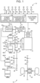
- a vehicle 10 includes an engine 12, a first electric motor MG1, and a second electric motor MG2.
- the vehicle 10 further includes driving wheels 14 and a power transmission device 16 that is provided in a power transmission path between the engine 12 and the driving wheels 14.
- the vehicle 10 according to the embodiment is a motor-driven vehicle, particularly, a hybrid electric vehicle, including the engine 12 and the second electric motor MG2 serving as power sources.
- the engine 12 is a known internal combustion engine.
- an engine torque Te which is a torque of the engine 12 is controlled by controlling an engine control device 50 provided in the vehicle 10 using an electronic control unit 90 which will be described later.
- Each of the first electric motor MG1 and the second electric motor MG2 is an electric rotary machine, that is, a so-called motor generator.
- the first electric motor MG1 and the second electric motor MG2 are connected to a high-voltage battery 54 provided in the vehicle 10 via an inverter 52 provided in the vehicle 10.
- an MG1 torque Tg which is a torque of the first electric motor MG1 and an MG2 torque Tm which is a torque of the second electric motor MG2 are controlled by controlling the inverter 52 using the electronic control unit 90 which will be described later.
- the first electric motor MG1 and the second electric motor MG2 are provided in a case 18 attached to a vehicle body.
- the power transmission device 16 includes a damper 20, an input shaft 22, a speed change unit 24, a combined gear 26, a driven gear 28, a driven shaft 30, a final gear 32, a differential gear 34, and a reduction gear 36 in the case 18.
- the power transmission device 16 further includes a rotor shaft RSmg1 integrally connected to a rotor MGlr of the first electric motor MG1 and a rotor shaft RSmg2 integrally connected to a rotor MG2r of the second electric motor MG2 in the case 18.
- the power transmission device 16 further includes a pair of drive shafts 38 connected to the differential gear 34.
- the input shaft 22 serves as an input rotary member of the speed change unit 24 and is connected to a crankshaft 12a of the engine 12 via the damper 20 or the like. Power from the engine 12 is input to the input shaft 22.
- the speed change unit 24 is connected to the input shaft 22.
- the combined gear 26 is a rotary member on an output side of the speed change unit 24.
- a drive gear 26a is formed in a part of an outer circumferential surface of the combined gear 26.
- the drive gear 26a is an output rotary member of the speed change unit 24.
- the driven gear 28 engages with the drive gear 26a.
- the driven shaft 30 fixes the driven gear 28 and the final gear 32 such that they cannot rotate relatively.
- the final gear 32 has a diameter smaller than that of the driven gear 28 and engages with a differential ring gear 34a of the differential gear 34.
- the reduction gear 36 has a diameter smaller than that of the driven gear 28 and engages with the driven gear 28.
- the rotor shaft RSmg2 is connected to the reduction gear 36, and the second electric motor MG2 is connected thereto in a power-transferable manner.
- the power transmission device 16 transmits power output from the engine 12 to the driven gear 28 via the speed change unit 24.
- the power transmission device 16 transmits power output from the second electric motor MG2 to the driven gear 28 via the reduction gear 36.
- the power transmission device 16 transmits power transmitted to the driven gear 28 to the driving wheels 14 sequentially via the driven shaft 30, the final gear 32, the differential gear 34, the drive shaft 38, and the like.
- the speed change unit 24 includes a first electric motor MG1, a rotor shaft RSmg1, and a planetary gear device 40.
- the planetary gear device 40 is a planetary gear device including a sun gear S, a carrier CA, a ring gear R, and a pinion P.
- the rotor shaft RSmg1 of the first electric motor MG1 is connected to the sun gear S in a power-transferable manner.
- the engine 12 is connected to the carrier CA via the input shaft 22 or the like in a power-transferable manner.
- the ring gear R is formed in a part of an inner circumferential surface of the combined gear 26 and is integrally connected to the drive gear 26a.
- the pinion P is supported by the carrier CA such that it can spin and revolve. The ring gear R engages with the sun gear S via the pinion P.
- the first electric motor MG1 is an electric motor connected to the planetary gear device 40 in a power-transferable manner.
- the planetary gear device 40 is a power split mechanism that mechanically splits the power of the engine 12 input to the carrier CA to the first electric motor MG1 and the drive gear 26a.
- the speed change unit 24 is an electrical speed change mechanism which is controlled by the first electric motor MG1.
- the vehicle 10 further includes a mechanical oil pump (hereinafter referred to as MOP) 56.
- MOP 56 is connected to the input shaft 22 in a power-transferable manner.
- the MOP 56 is rotationally driven by the engine 12 to supply oil Fld which is used for lubrication or cooling of constituent parts of the power transmission device 16.
- FIG. 2 is a diagram illustrating an example of an electrical configuration of an electric power control circuit 64 including the inverter 52 or the like which is provided in the vehicle 10.
- the high-voltage battery 54 serving as a storage battery is a DC power supply which is chargeable/dischargeable and is, for example, a secondary battery such as a nickel-hydride secondary battery or a lithium-ion battery.
- Stored electric power is supplied from the high-voltage battery 54 to the first electric motor MG1 or the second electric motor MG2 via the electric power control circuit 64. Electric power based on power generation control of the first electric motor MG1 or electric power based on regeneration control of the second electric motor MG2 is supplied to the high-voltage battery 54 via the electric power control circuit 64.
- the high-voltage battery 54 is a vehicle-driving battery.
- a DCDC converter 62 is connected to the high-voltage battery 54.
- the DCDC converter 62 serves as a charging device that steps down a voltage of the high-voltage battery 54 to a voltage equivalent to that of an auxiliary-machine battery 58 and charges the auxiliary-machine battery 58.
- the auxiliary-machine battery 58 supplies electric power for operating auxiliary machines provided in the vehicle 10.
- the auxiliary-machine battery 58 supplies electric power for operating the electronic control unit 90 which will be described later or the like.
- the electric power control circuit 64 includes an inverter 52 that controls electric power which is transmitted between the high-voltage battery 54 and the first electric motor MG1 and the second electric motor MG2. Since the voltage of the high-voltage battery 54 is high, the electric power control circuit 64 according to this embodiment does not include a step-up converter that steps up the voltage of the high-voltage battery 54 and supplies the stepped-up voltage to the inverter 52, and steps-down a voltage converted to a DC voltage by the inverter 52 and supplies the stepped-down voltage to the high-voltage battery 54.
- the inverter 52 includes an MG1 power module 68, an MG2 power module 70, and a capacitor 72.
- the MG1 power module 68 includes six transistors 74u, 74v, 74w, 76u, 76v, and 76w and six diodes 75u, 75v, 75w, 77u, 77v, and 77w connected in anti-parallel to the transistors 74u, 74v, 74w, 76u, 76v, and 76w.
- the transistors 74u, 74v, and 74w are referred to as transistors 74
- the transistors 76u, 76v, and 76w are referred to as transistors 76.
- the MG1 power module 68 constitutes a three-phase bridge circuit of a U phase, a V phase, and a W phase using the transistors 74 and 76 and the like.
- the transistors 74 and 76 serve as switching elements and convert a direct current to a three-phase alternating current by driving turn-on/off thereof.
- the transistors 74 constitute an upper arm in the transistors 74 and 76.
- the transistors 76 constitute a lower arm in the transistors 74 and 76.
- the MG2 power module 70 has the same configuration as the MG1 power module 68 and thus description of the MG2 power module 70 will be omitted.
- Each of the first electric motor MG1 and the second electric motor MG2 is a three-phase AC synchronous electric motor that is driven by the inverter 52 including a plurality of switching elements.
- the inverter 52 converts a direct current from the high-voltage battery 54 to an AC current for driving the first electric motor MG1 and the second electric motor MG2.
- the inverter 52 converts an alternating current generated by the first electric motor MG1 using the power of the engine 12 and an alternating current generated by the second electric motor MG2 using a regenerative brake to direct currents and supplies the direct currents to the high-voltage battery 54.
- the inverter 52 supplies the alternating current generated by the first electric motor MG1 as electric power for driving the second electric motor MG2 according to a travel state.
- FIG. 3 illustrates a sectional structure of the transistors 74 and 76 constituted as a semiconductor chip of Si, GaN, or the like and serving as the switching elements.
- the transistors 74 and 76 are interposed between an emitter-side path 80 and a collector-side path 82.
- the emitter-side path 80 includes an element upper solder 80a, a copper block 80b, a CB upper solder 80c, a heat spreader 80d, a first upper grease layer 80e, a ceramic plate 80f, a second upper grease layer 80g, and an upper cooler fin 80h which are sequentially stacked on the transistors 74 and 76.
- the collector-side path 82 includes an element lower solder 82a, a heat spreader 82b, a first lower grease layer 82c, a ceramic plate 82d, a second lower grease layer 82e, and a lower cooler fin 82f which are sequentially stacked under the transistors 74 and 76.
- the first upper grease layer 80e, the second upper grease layer 80g, the first lower grease layer 82c, and the second lower grease layer 82e which are inserted into the transistors 74 and 76 are expanded due to self-heating of the transistors 74 and 76 and extruded to the outside of the transistors 74 and 76, and are not returned to the inside of the transistors 74 and 76 when the self-heating of the transistors 74 and 76 converges.
- the number of repetitions of heating and heat dissipation of the switching elements affects (contributes to) a deterioration mode of the inverter which is called grease-missing deterioration. Accordingly, it is preferable to decrease the number of repetitions of heating and heat dissipation of the switching elements.
- the vehicle 10 is provided with a cooling circuit 84 which is a closed circuit for cooling the high-voltage battery 54 which is a storage battery and the inverter 52 by circulating a refrigerant using a water pump which is not illustrated with water used as the refrigerant.
- the cooling circuit 84 includes an oil cooler 88 configured to perform exchange of heat between oil (a refrigerant) circulating in an electric motor cooling circuit 86 with an oil pump (not illustrated) to cool the first electric motor MG1 and the second electric motor MG2 and water in the cooling circuit 84.
- the cooling circuit 84 includes a radiator as needed.
- the vehicle 10 includes an electronic control unit 90 which is a controller including a control device for the vehicle 10 associated with control of the engine 12, the electric motor, and the like.
- the electronic control unit 90 includes, for example, a so-called microcomputer including a CPU, a RAM, a ROM, and an input/output interface.
- the electronic control unit 90 performs various types of control of the vehicle 10 by causing the CPU to perform signal processing in accordance with a program stored in advance in the ROM using a temporary storage function of the RAM.
- various sensors for example, an engine rotation speed sensor 91, an output rotation speed sensor 92, an
- the electronic control unit 90 outputs various instruction signals (for example, an engine control instruction signal Se for controlling the engine 12 and an MG control instruction signal Smg for controlling the first electric motor MG1 and the second electric motor MG2) to various devices (for example, the engine control device 50 and the inverter 52) provided in the vehicle 10.
- various instruction signals for example, an engine control instruction signal Se for controlling the engine 12 and an MG control instruction signal Smg for controlling the first electric motor MG1 and the second electric motor MG2
- various devices for example, the engine control device 50 and the inverter 52
- the electronic control unit 90 functionally includes a power source control unit 102 and a heat generation control unit 104 for realizing various types of control in the vehicle 10.
- the power source control unit 102 has an engine control function of controlling the operation of the engine 12 and an electric motor control function of controlling the operation of the first electric motor MG1 and the second electric motor MG2 via the inverter 52.
- the power source control unit 102 calculates a required drive quantity for the vehicle 10 from a driver, for example, by applying the accelerator operation amount ⁇ acc and the vehicle speed V to a required drive quantity map.
- the required drive quantity map is a relationship for calculating the required drive quantity which is acquired and stored by experiment or design in advance, that is, which is determined in advance.
- the required drive quantity is, for example, a drive torque Tr required for the vehicle 10, that is, a required drive torque Trdem [Nm] for the driving wheels 14.
- the required drive torque Trdem is a required drive power Prdem [W] at the vehicle speed V at that time.
- a required drive force Frdem [N] for the driving wheels 14 or the like may be used as the required drive quantity.
- the power source control unit 102 outputs an engine control instruction signal Se and an MG control instruction signal Smg to realize the required drive power Prdem, for example, in consideration of a transmission loss, an auxiliary-machine load, and the like.
- the engine control instruction signal Se is an instruction value of an engine power Pe which is the power of the engine 12 for outputting the engine torque Te at the engine rotation speed Ne at that time in consideration of an engine-optimal fuel-efficiency point or the like.
- the MG control instruction signal Smg is an instruction value of electric power Wg generated by the first electric motor MG1 outputting an MG1 torque Tg at the MG1 rotation speed Ng at the time of outputting an instruction as a reaction torque of the engine torque Te.
- the MG control instruction signal Smg is an instruction value of electric power Wm consumed in the second electric motor MG2 outputting an MG2 torque Tm at the MG2 rotation speed Nm at the time of outputting an instruction of the generated electric power Wg.
- the engine-optimal fuel-efficiency point is predetermined, for example, as an engine operating point at which total fuel efficiency in the vehicle 10 is the best, for example, in consideration of charging/discharging efficiency of the high-voltage battery 54 or transmission efficiency of the power transmission device 16 along with fuel efficiency of the engine 12 alone.
- the power source control unit 102 sets a travel mode of the vehicle 10 to a BEV travel mode when the required drive power Prdem is in a BEV travel area which is less than a predetermined threshold value.
- the power source control unit 102 sets the travel mode of the vehicle 10 to an HEV travel mode when the required drive power Prdem is in an HEV travel area equal to or greater than the predetermined threshold value.
- the power source control unit 102 sets the HEV travel mode.
- the heat generation control unit 104 causes at least one inverter 52 to emit heat by passing a constant inverter current (a direct current) Iinv1 for warmup through the at least one inverter 52 for a predetermined time and transfers heat generated from the at least one inverter 52 to the high-voltage battery (storage battery) 54 via the cooling circuit 84 to cause the high-voltage battery 54 to warm up.
- a constant inverter current a direct current
- the warmup-requirement determination temperature Td is set to a temperature at which a chargeable/dischargeable electric power range of the high-voltage battery (storage battery) 54 is narrowed and control of the vehicle 10 is hindered, for example, 0°C.
- the constant inverter current (a direct current) Iinv1 flows through, for example, at least one of the transistors 74u, 74v, and 74w, at least one coil of the first electric motor MG1, and at least one of the transistors 76u, 76v, and 76w.
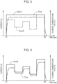
- FIG. 5 illustrates a current for causing the heat generation control unit 104 to operate one inverter 52.
- a constant inverter current Iinv indicated by a solid line is, for example, 200 A, and a predetermined time t1-t2 is, for example, 30 seconds.
- a one-dot chain line indicates the temperature Tinv of the inverter 52, and a dotted line indicates an inverter current Iinv2 in a comparative example illustrated in FIG. 6 .
- the constant inverter current Iinv1 substantially includes the inverter current Iinv2 in the comparative example varying in a pulse shape every 6 seconds and is greater than an integrated value (an area value) of the inverter current Iinv2 in the comparative example.
- FIG. 6 is a diagram illustrating the operation of heat generation control in the comparative example of the heat generation control unit 104 and illustrating the same two-dimensional coordinates as in FIG. 5 .
- the heat generation control unit 104 in this case sequentially calculates an amount of discharged heat required for warmup of the high-voltage battery (storage battery) 54 based on (in response to) the change in temperature Tb of the high-voltage battery 54 with a period shorter than that in FIG. 5 , for example, a period of 6 seconds, sequentially calculates the inverter current Iinv2 for generating the calculated heat, and operates at least one inverter 52 with the inverter current Iinv2.
- a solid line in FIG. 6 indicates the inverter current Iinv2 varying every predetermined time of, for example, 6 seconds due to an influence of wind or the like, and a one-dot chain line indicates the temperature Tinv of the inverter 52.
- FIG. 7 is a flowchart illustrating a principal part of the control operation which is performed by the electronic control unit 90.
- Step S 1 Step is omitted hereinafter
- this routine ends.
- the determination result of S 1 is positive
- Td the preset warmup-requirement determination temperature
- inverter heat generation control is performed for a predetermined time in S3 corresponding to the heat generation control unit 104.
- At least one inverter 52 is caused to emit heat by passing the constant inverter current Iinv1 for warmup through the at least one inverter 52 for a predetermined time, and the heat emitted from the at least one inverter 52 is transferred to the high-voltage battery (storage battery) 54 via the cooling circuit 84 to warm the high-voltage battery 54.
- the heat generation control unit 104 causes at least one inverter 52 to emit heat by passing the constant current Iinv1 through the inverter for the predetermined time, and the heat emitted from the at least one inverter 52 warms the high-voltage battery (storage battery) 54 via the cooling circuit 84. Accordingly, control for warming the high-voltage battery (storage battery) 54 is simply performed by passing the constant current linv1 through the inverter 52 for the predetermined time.
- This inverter heat generation control can also be applied to a vehicle 10 not including a step-up converter.
- the heat generation control unit 104 causes the inverter 52 to emit heat by passing the constant inverter current (a direct current) Iinv1 through the inverter 52 for the predetermined time, heating and heat dissipation of the inverter 52 is not repeated and the deterioration mode of the inverter called grease-missing deterioration is curbed.
- the inverter heat generation control performed by the heat generation control unit 104 is performed when the P range has been selected as the shift range of the vehicle 10. In the P range, since movement of the vehicle is prohibited by the parking lock mechanism of the vehicle 10, there is an advantage that the inverter heat generation control does not affect behavior of the vehicle 10.
- the inverter heat generation control performed by the heat generation control unit 104 is performed when the temperature Tb of the high-voltage battery (storage battery) 54 is lower than the preset warmup-requirement determination temperature Td of the high-voltage battery (storage battery) 54. Accordingly, warmup of the high-voltage battery (storage battery) 54 is performed at a low temperature at which chargeable/dischargeable electric power range is relatively narrow, and the chargeable/dischargeable electric power range of the high-voltage battery (storage battery) 54 is rapidly broadened.
- the constant current Iinv1 in the inverter heat generation control performed by the heat generation control unit 104 has values including a current Iinv2 which is varied to generate an amount of discharged heat required for increasing the temperature Tb of the high-voltage battery (storage battery) 54 which is calculated based on the temperature Tb of the high-voltage battery (storage battery) 54 in comparison with a comparative example in which the current Iinv2 which is varied to generate the amount of discharged heat is used. Accordingly, control for warming the high-voltage battery (storage battery) 54 is simplified.
- the refrigerant of the cooling circuit 84 is water
- the cooling circuit 84 includes the oil cooler 88 that performs exchange of heat between the oil in the electric motor cooling circuit 86 cooling the first electric motor MG1 and the second electric motor MG2 and the water in the cooling circuit 84.
- the heat generation control unit 104 causes the coils of the first electric motor MG1 and the second electric motor MG2 to emit heat by passing the constant current linv1 through the inverter 52 for the predetermined time
- the heat generated in the first electric motor MG1 and the second electric motor MG2 is also transferred to the high-voltage battery (storage battery) 54 via the oil cooler 88 and the cooling circuit 84 and contributes to warmup of the high-voltage battery (storage battery) 54.
- the vehicle 10 does not include a step-up converter between the high-voltage battery (storage battery) 54 and the inverter 52, but may include a step-up converter between the high-voltage battery (storage battery) 54 and the inverter 52.
- the vehicle 10 is a hybrid electric vehicle including the engine 12, the first electric motor MG1, and the second electric motor MG2 as power sources, but may be a motor-driven vehicle including an electric motor as a power source.
- the heat generation control unit 104 causes the constant inverter current (direct current) Iinv1 to pass through the inverter 52 for a predetermined time such that the inverter 52 generates heat for warming the high-voltage battery 54 as illustrated in FIG. 5 .
- the constant inverter current (direct current) Iinv1 or an instruction value of the inverter current (direct current) Iinv1 does not have to be strictly constant, and the amplitude or period thereof may vary to an extent that the inverter 52 does not repeat heating and heat dissipation causing grease-missing deterioration in the inverter (switching elements) 52.
Landscapes
- Engineering & Computer Science (AREA)
- Power Engineering (AREA)
- Chemical & Material Sciences (AREA)
- Manufacturing & Machinery (AREA)
- General Chemical & Material Sciences (AREA)
- Electrochemistry (AREA)
- Chemical Kinetics & Catalysis (AREA)
- Transportation (AREA)
- Mechanical Engineering (AREA)
- Sustainable Development (AREA)
- Sustainable Energy (AREA)
- Life Sciences & Earth Sciences (AREA)
- Microelectronics & Electronic Packaging (AREA)
- Physics & Mathematics (AREA)
- Combustion & Propulsion (AREA)
- Thermal Sciences (AREA)
- Automation & Control Theory (AREA)
- Electromagnetism (AREA)
- Electric Propulsion And Braking For Vehicles (AREA)
- Hybrid Electric Vehicles (AREA)
- Inverter Devices (AREA)
Abstract
At least one inverter (52) is heated by causing an inverter heat generation control unit to pass a predetermined current through the inverter for a predetermined time, and heating of the at least one inverter causes a high-voltage battery (54) (storage battery) to warm up via a cooling circuit. Accordingly, control for warmup of the high-voltage battery (storage battery) is simply performed by passing the predetermined current through the inverter for a predetermined time. This inverter heat generation control can also be applied to a vehicle not including a step-up converter.
Description
- The invention relates to a warmup device of a vehicular storage battery that warms up a storage battery in a vehicle in which a drive current from the storage battery is supplied to an electric motor via an inverter.
- In a vehicle including an inverter that controls a drive current from a storage battery which is supplied to an electric motor and a step-up converter that steps up a voltage of the storage battery through switching control of a switching element and outputs the stepped-up voltage to the inverter, a vehicle driving device that warms up the storage battery through self-heating of the storage battery by performing ripple temperature increase control for increasing a ripple current by decreasing a switching frequency of the step-up converter and thus increasing heating in an internal resistor of the storage battery has been proposed. An example thereof is a vehicle driving device described in
Japanese Unexamined Patent Application Publication No. 2010-259217 JP 2010-259217 A - A chargeable/dischargeable electric power range of a storage battery is narrowed at low temperatures. Accordingly, it is preferable to perform warmup in order to broaden the chargeable/dischargeable electric power range. However, a storage battery with a narrow chargeable/dischargeable electric power range has to be caused to perform self-heating at low temperatures, a switching frequency of a step-up converter for increasing a ripple current required for generation of heat from an internal resistor of the storage battery is calculated based on a detected temperature from a temperature sensor detecting a temperature of the storage battery, and thus there is a problem in that control becomes complicated. This technique cannot be applied to a vehicle not including a step-up converter and thus there is also a problem in that applicable vehicles are limited.
- The invention provides a control device for a vehicular storage battery that can simplify warmup control for warmup of a storage battery and be applicable to a vehicle not including a step-up converter.
- According to an aspect of the invention, there is provided a control device for a vehicular storage battery including: an inverter configured to control a drive current supplied from a storage battery to an electric motor; a cooling circuit configured to cool the storage battery and the inverter by circulating a refrigerant; and an inverter heat generation control unit configured to cause the inverter to emit heat by passing a predetermined current through the inverter for a predetermined time and to cause the storage battery to warm up via the cooling circuit.
- According to the aspect of the invention, the inverter is heated by causing an inverter heat generation control unit to pass a predetermined current through the inverter, and heating of the inverter causes the storage battery to warm up via the cooling circuit. Accordingly, control for warmup of the storage battery is simply performed by passing the predetermined current through the inverter. This inverter heat generation control can also be applied to a vehicle not including a step-up converter.
- Features, advantages, and technical and industrial significance of exemplary embodiments of the invention will be described below with reference to the accompanying drawings, in which like signs denote like elements, and wherein:
-
FIG. 1 is a diagram schematically illustrating a configuration of a vehicle to which the invention is applied and illustrating a principal part of a control function and a control system for various types of control in the vehicle; -
FIG. 2 is a diagram specifically illustrating a storage battery and a power control circuit for controlling driving of an electric motor provided in the vehicle illustrated inFIG. 1 ; -
FIG. 3 is a diagram schematically illustrating a refrigerant circulation circuit that circulates a refrigerant to cool a storage battery and an inverter and that is provided in the vehicle illustrated inFIG. 1 ; -
FIG. 4 is a diagram schematically illustrating a configuration of an inverter illustrated inFIG. 2 ; -
FIG. 5 is a timing chart illustrating operations which are performed by a heat generation control unit illustrated inFIG. 1 ; -
FIG. 6 is a timing chart illustrating operations which are performed by a heat generation control unit according to a comparative example; and -
FIG. 7 is a flowchart illustrating a control operation which is performed by the heat generation control unit illustrated inFIG. 1 . - Hereinafter, an embodiment of the invention will be described in detail with reference to the accompanying drawings.
- In
FIG. 1 , avehicle 10 includes anengine 12, a first electric motor MG1, and a second electric motor MG2. Thevehicle 10 further includesdriving wheels 14 and apower transmission device 16 that is provided in a power transmission path between theengine 12 and thedriving wheels 14. Thevehicle 10 according to the embodiment is a motor-driven vehicle, particularly, a hybrid electric vehicle, including theengine 12 and the second electric motor MG2 serving as power sources. - The
engine 12 is a known internal combustion engine. In theengine 12, an engine torque Te which is a torque of theengine 12 is controlled by controlling anengine control device 50 provided in thevehicle 10 using anelectronic control unit 90 which will be described later. - Each of the first electric motor MG1 and the second electric motor MG2 is an electric rotary machine, that is, a so-called motor generator. The first electric motor MG1 and the second electric motor MG2 are connected to a high-
voltage battery 54 provided in thevehicle 10 via aninverter 52 provided in thevehicle 10. In the first electric motor MG1 and the second electric motor MG2, an MG1 torque Tg which is a torque of the first electric motor MG1 and an MG2 torque Tm which is a torque of the second electric motor MG2 are controlled by controlling theinverter 52 using theelectronic control unit 90 which will be described later. The first electric motor MG1 and the second electric motor MG2 are provided in acase 18 attached to a vehicle body. - The
power transmission device 16 includes adamper 20, aninput shaft 22, aspeed change unit 24, a combinedgear 26, a drivengear 28, a drivenshaft 30, afinal gear 32, adifferential gear 34, and areduction gear 36 in thecase 18. Thepower transmission device 16 further includes a rotor shaft RSmg1 integrally connected to a rotor MGlr of the first electric motor MG1 and a rotor shaft RSmg2 integrally connected to a rotor MG2r of the second electric motor MG2 in thecase 18. Thepower transmission device 16 further includes a pair ofdrive shafts 38 connected to thedifferential gear 34. - The
input shaft 22 serves as an input rotary member of thespeed change unit 24 and is connected to acrankshaft 12a of theengine 12 via thedamper 20 or the like. Power from theengine 12 is input to theinput shaft 22. Thespeed change unit 24 is connected to theinput shaft 22. The combinedgear 26 is a rotary member on an output side of thespeed change unit 24. Adrive gear 26a is formed in a part of an outer circumferential surface of the combinedgear 26. Thedrive gear 26a is an output rotary member of thespeed change unit 24. The drivengear 28 engages with thedrive gear 26a. The drivenshaft 30 fixes the drivengear 28 and thefinal gear 32 such that they cannot rotate relatively. Thefinal gear 32 has a diameter smaller than that of the drivengear 28 and engages with adifferential ring gear 34a of thedifferential gear 34. Thereduction gear 36 has a diameter smaller than that of the drivengear 28 and engages with the drivengear 28. The rotor shaft RSmg2 is connected to thereduction gear 36, and the second electric motor MG2 is connected thereto in a power-transferable manner. - The
power transmission device 16 transmits power output from theengine 12 to the drivengear 28 via thespeed change unit 24. Thepower transmission device 16 transmits power output from the second electric motor MG2 to the drivengear 28 via thereduction gear 36. Thepower transmission device 16 transmits power transmitted to the drivengear 28 to thedriving wheels 14 sequentially via the drivenshaft 30, thefinal gear 32, thedifferential gear 34, thedrive shaft 38, and the like. - The
speed change unit 24 includes a first electric motor MG1, a rotor shaft RSmg1, and aplanetary gear device 40. Theplanetary gear device 40 is a planetary gear device including a sun gear S, a carrier CA, a ring gear R, and a pinion P. The rotor shaft RSmg1 of the first electric motor MG1 is connected to the sun gear S in a power-transferable manner. Theengine 12 is connected to the carrier CA via theinput shaft 22 or the like in a power-transferable manner. The ring gear R is formed in a part of an inner circumferential surface of the combinedgear 26 and is integrally connected to thedrive gear 26a. The pinion P is supported by the carrier CA such that it can spin and revolve. The ring gear R engages with the sun gear S via the pinion P. - Power of the
engine 12 is input to theplanetary gear device 40 via theinput shaft 22. The first electric motor MG1 is an electric motor connected to theplanetary gear device 40 in a power-transferable manner. Theplanetary gear device 40 is a power split mechanism that mechanically splits the power of theengine 12 input to the carrier CA to the first electric motor MG1 and thedrive gear 26a. Thespeed change unit 24 is an electrical speed change mechanism which is controlled by the first electric motor MG1. - The
vehicle 10 further includes a mechanical oil pump (hereinafter referred to as MOP) 56. TheMOP 56 is connected to theinput shaft 22 in a power-transferable manner. TheMOP 56 is rotationally driven by theengine 12 to supply oil Fld which is used for lubrication or cooling of constituent parts of thepower transmission device 16. -
FIG. 2 is a diagram illustrating an example of an electrical configuration of an electricpower control circuit 64 including theinverter 52 or the like which is provided in thevehicle 10. - The high-
voltage battery 54 serving as a storage battery is a DC power supply which is chargeable/dischargeable and is, for example, a secondary battery such as a nickel-hydride secondary battery or a lithium-ion battery. - Stored electric power is supplied from the high-
voltage battery 54 to the first electric motor MG1 or the second electric motor MG2 via the electricpower control circuit 64. Electric power based on power generation control of the first electric motor MG1 or electric power based on regeneration control of the second electric motor MG2 is supplied to the high-voltage battery 54 via the electricpower control circuit 64. The high-voltage battery 54 is a vehicle-driving battery. - A
DCDC converter 62 is connected to the high-voltage battery 54. TheDCDC converter 62 serves as a charging device that steps down a voltage of the high-voltage battery 54 to a voltage equivalent to that of an auxiliary-machine battery 58 and charges the auxiliary-machine battery 58. The auxiliary-machine battery 58 supplies electric power for operating auxiliary machines provided in thevehicle 10. The auxiliary-machine battery 58 supplies electric power for operating theelectronic control unit 90 which will be described later or the like. - The electric
power control circuit 64 includes aninverter 52 that controls electric power which is transmitted between the high-voltage battery 54 and the first electric motor MG1 and the second electric motor MG2. Since the voltage of the high-voltage battery 54 is high, the electricpower control circuit 64 according to this embodiment does not include a step-up converter that steps up the voltage of the high-voltage battery 54 and supplies the stepped-up voltage to theinverter 52, and steps-down a voltage converted to a DC voltage by theinverter 52 and supplies the stepped-down voltage to the high-voltage battery 54. - The
inverter 52 includes anMG1 power module 68, anMG2 power module 70, and a capacitor 72. TheMG1 power module 68 includes sixtransistors diodes transistors transistors transistors 74, and thetransistors transistors 76. TheMG1 power module 68 constitutes a three-phase bridge circuit of a U phase, a V phase, and a W phase using thetransistors transistors transistors 74 constitute an upper arm in thetransistors transistors 76 constitute a lower arm in thetransistors MG2 power module 70 has the same configuration as theMG1 power module 68 and thus description of theMG2 power module 70 will be omitted. Each of the first electric motor MG1 and the second electric motor MG2 is a three-phase AC synchronous electric motor that is driven by theinverter 52 including a plurality of switching elements. - The
inverter 52 converts a direct current from the high-voltage battery 54 to an AC current for driving the first electric motor MG1 and the second electric motor MG2. Theinverter 52 converts an alternating current generated by the first electric motor MG1 using the power of theengine 12 and an alternating current generated by the second electric motor MG2 using a regenerative brake to direct currents and supplies the direct currents to the high-voltage battery 54. Theinverter 52 supplies the alternating current generated by the first electric motor MG1 as electric power for driving the second electric motor MG2 according to a travel state. -
FIG. 3 illustrates a sectional structure of thetransistors FIG. 3 , thetransistors side path 80 and a collector-side path 82. The emitter-side path 80 includes an elementupper solder 80a, acopper block 80b, a CBupper solder 80c, aheat spreader 80d, a firstupper grease layer 80e, aceramic plate 80f, a secondupper grease layer 80g, and an uppercooler fin 80h which are sequentially stacked on thetransistors side path 82 includes an elementlower solder 82a, aheat spreader 82b, a firstlower grease layer 82c, aceramic plate 82d, a secondlower grease layer 82e, and alower cooler fin 82f which are sequentially stacked under thetransistors upper grease layer 80e, the secondupper grease layer 80g, the firstlower grease layer 82c, and the secondlower grease layer 82e which are inserted into thetransistors transistors transistors transistors transistors - As illustrated in
FIG. 4 , thevehicle 10 is provided with acooling circuit 84 which is a closed circuit for cooling the high-voltage battery 54 which is a storage battery and theinverter 52 by circulating a refrigerant using a water pump which is not illustrated with water used as the refrigerant. Thecooling circuit 84 includes an oil cooler 88 configured to perform exchange of heat between oil (a refrigerant) circulating in an electricmotor cooling circuit 86 with an oil pump (not illustrated) to cool the first electric motor MG1 and the second electric motor MG2 and water in thecooling circuit 84. Thecooling circuit 84 includes a radiator as needed. - Referring back to
FIG. 1 , thevehicle 10 includes anelectronic control unit 90 which is a controller including a control device for thevehicle 10 associated with control of theengine 12, the electric motor, and the like. Theelectronic control unit 90 includes, for example, a so-called microcomputer including a CPU, a RAM, a ROM, and an input/output interface. Theelectronic control unit 90 performs various types of control of thevehicle 10 by causing the CPU to perform signal processing in accordance with a program stored in advance in the ROM using a temporary storage function of the RAM. - Various signals (for example, an engine rotation speed Ne (=an input rotation speed Ni), an output rotation speed No corresponding to a vehicle speed V, an MG1 rotation speed Ng which is a rotation speed of the first electric motor MG1, an MG2 rotation speed Nm, which is a rotation speed of the second electric motor MG2, an accelerator operation amount θacc, a throttle opening θth, a brake-on signal Bon, a shift lever operation position Psft, and a temperature Tb of the high-voltage battery 54) based on detection values from various sensors (for example, an engine
rotation speed sensor 91, an outputrotation speed sensor 92, an MG1rotation speed sensor 93, an MG2rotation speed sensor 94, an acceleratoroperation amount sensor 95, athrottle opening sensor 96, abrake switch 97, a shift lever operationposition detection switch 98, and a temperature sensor 99) provided in thevehicle 10 are supplied to theelectronic control unit 90. - The
electronic control unit 90 outputs various instruction signals (for example, an engine control instruction signal Se for controlling theengine 12 and an MG control instruction signal Smg for controlling the first electric motor MG1 and the second electric motor MG2) to various devices (for example, theengine control device 50 and the inverter 52) provided in thevehicle 10. - The
electronic control unit 90 functionally includes a powersource control unit 102 and a heatgeneration control unit 104 for realizing various types of control in thevehicle 10. - The power
source control unit 102 has an engine control function of controlling the operation of theengine 12 and an electric motor control function of controlling the operation of the first electric motor MG1 and the second electric motor MG2 via theinverter 52. - The power
source control unit 102 calculates a required drive quantity for thevehicle 10 from a driver, for example, by applying the accelerator operation amount θacc and the vehicle speed V to a required drive quantity map. The required drive quantity map is a relationship for calculating the required drive quantity which is acquired and stored by experiment or design in advance, that is, which is determined in advance. The required drive quantity is, for example, a drive torque Tr required for thevehicle 10, that is, a required drive torque Trdem [Nm] for the drivingwheels 14. In other words, the required drive torque Trdem is a required drive power Prdem [W] at the vehicle speed V at that time. A required drive force Frdem [N] for the drivingwheels 14 or the like may be used as the required drive quantity. - The power
source control unit 102 outputs an engine control instruction signal Se and an MG control instruction signal Smg to realize the required drive power Prdem, for example, in consideration of a transmission loss, an auxiliary-machine load, and the like. For example, the engine control instruction signal Se is an instruction value of an engine power Pe which is the power of theengine 12 for outputting the engine torque Te at the engine rotation speed Ne at that time in consideration of an engine-optimal fuel-efficiency point or the like. The MG control instruction signal Smg is an instruction value of electric power Wg generated by the first electric motor MG1 outputting an MG1 torque Tg at the MG1 rotation speed Ng at the time of outputting an instruction as a reaction torque of the engine torque Te. The MG control instruction signal Smg is an instruction value of electric power Wm consumed in the second electric motor MG2 outputting an MG2 torque Tm at the MG2 rotation speed Nm at the time of outputting an instruction of the generated electric power Wg. The engine-optimal fuel-efficiency point is predetermined, for example, as an engine operating point at which total fuel efficiency in thevehicle 10 is the best, for example, in consideration of charging/discharging efficiency of the high-voltage battery 54 or transmission efficiency of thepower transmission device 16 along with fuel efficiency of theengine 12 alone. - The power
source control unit 102 sets a travel mode of thevehicle 10 to a BEV travel mode when the required drive power Prdem is in a BEV travel area which is less than a predetermined threshold value. On the other hand, the powersource control unit 102 sets the travel mode of thevehicle 10 to an HEV travel mode when the required drive power Prdem is in an HEV travel area equal to or greater than the predetermined threshold value. On the other hand, when the required drive power Prdem is in the BEV travel area and the high-voltage battery 54 needs to be charged or theengine 12 or the like needs to warm up, the powersource control unit 102 sets the HEV travel mode. - When a P range (a parking range) is selected as a shift range of the
vehicle 10 and the temperature Tb of the high-voltage battery 54 is lower than a preset warmup-requirement determination temperature Td of the high-voltage battery 54, the heatgeneration control unit 104 causes at least oneinverter 52 to emit heat by passing a constant inverter current (a direct current) Iinv1 for warmup through the at least oneinverter 52 for a predetermined time and transfers heat generated from the at least oneinverter 52 to the high-voltage battery (storage battery) 54 via thecooling circuit 84 to cause the high-voltage battery 54 to warm up. The warmup-requirement determination temperature Td is set to a temperature at which a chargeable/dischargeable electric power range of the high-voltage battery (storage battery) 54 is narrowed and control of thevehicle 10 is hindered, for example, 0°C. The constant inverter current (a direct current) Iinv1 flows through, for example, at least one of thetransistors transistors -
FIG. 5 illustrates a current for causing the heatgeneration control unit 104 to operate oneinverter 52. InFIG. 5 , a constant inverter current Iinv indicated by a solid line is, for example, 200 A, and a predetermined time t1-t2 is, for example, 30 seconds. InFIG. 5 , a one-dot chain line indicates the temperature Tinv of theinverter 52, and a dotted line indicates an inverter current Iinv2 in a comparative example illustrated inFIG. 6 . The constant inverter current Iinv1 substantially includes the inverter current Iinv2 in the comparative example varying in a pulse shape every 6 seconds and is greater than an integrated value (an area value) of the inverter current Iinv2 in the comparative example. -
FIG. 6 is a diagram illustrating the operation of heat generation control in the comparative example of the heatgeneration control unit 104 and illustrating the same two-dimensional coordinates as inFIG. 5 . The heatgeneration control unit 104 in this case sequentially calculates an amount of discharged heat required for warmup of the high-voltage battery (storage battery) 54 based on (in response to) the change in temperature Tb of the high-voltage battery 54 with a period shorter than that inFIG. 5 , for example, a period of 6 seconds, sequentially calculates the inverter current Iinv2 for generating the calculated heat, and operates at least oneinverter 52 with the inverter current Iinv2. A solid line inFIG. 6 indicates the inverter current Iinv2 varying every predetermined time of, for example, 6 seconds due to an influence of wind or the like, and a one-dot chain line indicates the temperature Tinv of theinverter 52. -
FIG. 7 is a flowchart illustrating a principal part of the control operation which is performed by theelectronic control unit 90. In Step S 1 (Step is omitted hereinafter) ofFIG. 7 , it is determined whether the P range in which movement of thevehicle 10 is prohibited by a parking lock mechanism of thevehicle 10 has been selected in the shift range of thevehicle 10. When the determination result ofS 1 is negative, this routine ends. On the other hand, when the determination result ofS 1 is positive, it is determined in S2 whether the temperature Tb of the high-voltage battery 54 is lower than the preset warmup-requirement determination temperature Td of the high-voltage battery 54, for example, 0°C. When the determination result of S2 is negative, this routine ends. On the other hand, when the determination result of S2 is positive, inverter heat generation control is performed for a predetermined time in S3 corresponding to the heatgeneration control unit 104. At least oneinverter 52 is caused to emit heat by passing the constant inverter current Iinv1 for warmup through the at least oneinverter 52 for a predetermined time, and the heat emitted from the at least oneinverter 52 is transferred to the high-voltage battery (storage battery) 54 via thecooling circuit 84 to warm the high-voltage battery 54. - As described above, with the
electronic control unit 90 according to this embodiment, the heatgeneration control unit 104 causes at least oneinverter 52 to emit heat by passing the constant current Iinv1 through the inverter for the predetermined time, and the heat emitted from the at least oneinverter 52 warms the high-voltage battery (storage battery) 54 via thecooling circuit 84. Accordingly, control for warming the high-voltage battery (storage battery) 54 is simply performed by passing the constant current linv1 through theinverter 52 for the predetermined time. This inverter heat generation control can also be applied to avehicle 10 not including a step-up converter. Since the heatgeneration control unit 104 causes theinverter 52 to emit heat by passing the constant inverter current (a direct current) Iinv1 through theinverter 52 for the predetermined time, heating and heat dissipation of theinverter 52 is not repeated and the deterioration mode of the inverter called grease-missing deterioration is curbed. - With the
electronic control unit 90 according to this embodiment, the inverter heat generation control performed by the heatgeneration control unit 104 is performed when the P range has been selected as the shift range of thevehicle 10. In the P range, since movement of the vehicle is prohibited by the parking lock mechanism of thevehicle 10, there is an advantage that the inverter heat generation control does not affect behavior of thevehicle 10. - With the
electronic control unit 90 according to this embodiment, the inverter heat generation control performed by the heatgeneration control unit 104 is performed when the temperature Tb of the high-voltage battery (storage battery) 54 is lower than the preset warmup-requirement determination temperature Td of the high-voltage battery (storage battery) 54. Accordingly, warmup of the high-voltage battery (storage battery) 54 is performed at a low temperature at which chargeable/dischargeable electric power range is relatively narrow, and the chargeable/dischargeable electric power range of the high-voltage battery (storage battery) 54 is rapidly broadened. - With the
electronic control unit 90 according to this embodiment, the constant current Iinv1 in the inverter heat generation control performed by the heatgeneration control unit 104 has values including a current Iinv2 which is varied to generate an amount of discharged heat required for increasing the temperature Tb of the high-voltage battery (storage battery) 54 which is calculated based on the temperature Tb of the high-voltage battery (storage battery) 54 in comparison with a comparative example in which the current Iinv2 which is varied to generate the amount of discharged heat is used. Accordingly, control for warming the high-voltage battery (storage battery) 54 is simplified. - With the
electronic control unit 90 according to this embodiment, the refrigerant of thecooling circuit 84 is water, and thecooling circuit 84 includes theoil cooler 88 that performs exchange of heat between the oil in the electricmotor cooling circuit 86 cooling the first electric motor MG1 and the second electric motor MG2 and the water in thecooling circuit 84. Accordingly, when the heatgeneration control unit 104 causes the coils of the first electric motor MG1 and the second electric motor MG2 to emit heat by passing the constant current linv1 through theinverter 52 for the predetermined time, the heat generated in the first electric motor MG1 and the second electric motor MG2 is also transferred to the high-voltage battery (storage battery) 54 via theoil cooler 88 and thecooling circuit 84 and contributes to warmup of the high-voltage battery (storage battery) 54. As a result, it is possible to further promote warmup of the high-voltage battery (storage battery) 54. - While an embodiment of the invention has been described above in detail with reference to the drawings, the invention may be applied to other aspects.
- For example, the
vehicle 10 according to the embodiment does not include a step-up converter between the high-voltage battery (storage battery) 54 and theinverter 52, but may include a step-up converter between the high-voltage battery (storage battery) 54 and theinverter 52. - The
vehicle 10 according to the embodiment is a hybrid electric vehicle including theengine 12, the first electric motor MG1, and the second electric motor MG2 as power sources, but may be a motor-driven vehicle including an electric motor as a power source. - In the
vehicle 10 according to the embodiment, the heatgeneration control unit 104 causes the constant inverter current (direct current) Iinv1 to pass through theinverter 52 for a predetermined time such that theinverter 52 generates heat for warming the high-voltage battery 54 as illustrated inFIG. 5 . The constant inverter current (direct current) Iinv1 or an instruction value of the inverter current (direct current) Iinv1 does not have to be strictly constant, and the amplitude or period thereof may vary to an extent that theinverter 52 does not repeat heating and heat dissipation causing grease-missing deterioration in the inverter (switching elements) 52. - The aforementioned description is merely an embodiment, and the invention can be realized in aspects with various modifications and improvements based on knowledge of those skilled in the art.
Claims (5)
- A control device for a vehicular storage battery (54) comprising:an inverter (52) configured to control a drive current supplied from a storage battery (54) to an electric motor (MG1,MG2);a cooling circuit (84) configured to cool the storage battery and the inverter by circulating a refrigerant; andan inverter heat generation control unit (104) configured to cause the inverter to emit heat by passing a predetermined current through the inverter for a predetermined time and to cause the storage battery to warm up via the cooling circuit.
- The control device for a vehicular storage battery according to claim 1, wherein inverter heat generation control which is performed by the inverter heat generation control unit (104) is performed when a parking range is selected as a shift range of the vehicle.
- The control device for a vehicular storage battery according to claim 1 or 2, wherein inverter heat generation control which is performed by the inverter heat generation control unit (104) is performed when a temperature of the storage battery (54) is lower than a preset warmup-requirement determination temperature of the storage battery.
- The control device for a vehicular storage battery according to any of claims 1 to 3, wherein the predetermined current has values including a current which is varied to generate an amount of discharged heat required for warmup of the storage battery (54) sequentially calculated based on change in temperature of the storage battery.
- The control device for a vehicular storage battery according to claim 1, wherein the refrigerant of the cooling circuit (84) is water, and
wherein the cooling circuit includes an oil cooler (88) configured to perform exchange of heat between oil in an electric motor cooling circuit (86) for cooling the electric motor and water in the cooling circuit.
Applications Claiming Priority (1)
| Application Number | Priority Date | Filing Date | Title |
|---|---|---|---|
| JP2023026760A JP2024119684A (en) | 2023-02-22 | 2023-02-22 | Vehicle battery warm-up device |
Publications (1)
| Publication Number | Publication Date |
|---|---|
| EP4420917A1 true EP4420917A1 (en) | 2024-08-28 |
Family
ID=89940909
Family Applications (1)
| Application Number | Title | Priority Date | Filing Date |
|---|---|---|---|
| EP24157672.7A Pending EP4420917A1 (en) | 2023-02-22 | 2024-02-14 | Warmup device of vehicular storage battery |
Country Status (5)
| Country | Link |
|---|---|
| US (1) | US20240283056A1 (en) |
| EP (1) | EP4420917A1 (en) |
| JP (1) | JP2024119684A (en) |
| KR (1) | KR20240130622A (en) |
| CN (1) | CN118539047A (en) |
Families Citing this family (2)
| Publication number | Priority date | Publication date | Assignee | Title |
|---|---|---|---|---|
| JP7426427B2 (en) * | 2022-03-31 | 2024-02-01 | 本田技研工業株式会社 | Temperature control device and vehicle |
| FR3166342A1 (en) * | 2024-09-17 | 2026-03-20 | Stellantis Auto Sas | METHOD FOR THERMOREGULATING A HEAT TRANSFER CIRCUIT COMPRISING A MOTOR AND A BATTERY |
Citations (7)
| Publication number | Priority date | Publication date | Assignee | Title |
|---|---|---|---|---|
| EP0704337A2 (en) * | 1994-09-29 | 1996-04-03 | Seiko Epson Corporation | A control apparatus for an electric automobile |
| US20100050676A1 (en) * | 2007-02-07 | 2010-03-04 | Toyota Jidosha Kabushiki Kaisha | Cooling system |
| JP2010259217A (en) | 2009-04-24 | 2010-11-11 | Toyota Motor Corp | Drive device |
| JP2012178930A (en) * | 2011-02-25 | 2012-09-13 | Denso Corp | Charge control device of battery |
| US20200214088A1 (en) * | 2018-12-26 | 2020-07-02 | Toyota Jidosha Kabushiki Kaisha | Vehicle warm-up control apparatus |
| US20200290427A1 (en) * | 2019-03-13 | 2020-09-17 | Toyota Jidosha Kabushiki Kaisha | Control device of vehicle cooling device |
| US20230021121A1 (en) * | 2020-03-27 | 2023-01-19 | Panasonic Intellectual Property Management Co., Ltd. | Vehicle, heat exchanger plate and battery pack |
Family Cites Families (5)
| Publication number | Priority date | Publication date | Assignee | Title |
|---|---|---|---|---|
| JP3886697B2 (en) * | 1999-04-27 | 2007-02-28 | アイシン・エィ・ダブリュ株式会社 | Drive device |
| JP2007028702A (en) * | 2005-07-12 | 2007-02-01 | Toyota Motor Corp | Secondary battery control device |
| JP2010119282A (en) * | 2008-10-17 | 2010-05-27 | Denso Corp | Thermal management system |
| JP2013158181A (en) * | 2012-01-31 | 2013-08-15 | Toyota Motor Corp | Inverter device equipped with dew condensation prevention function |
| EP3623183B1 (en) * | 2018-09-11 | 2020-12-02 | C.R.F. Società Consortile per Azioni | A system for thermal management of the components of a hybrid vehicle |
-
2023
- 2023-02-22 JP JP2023026760A patent/JP2024119684A/en active Pending
-
2024
- 2024-02-06 US US18/433,718 patent/US20240283056A1/en active Pending
- 2024-02-07 CN CN202410171795.6A patent/CN118539047A/en active Pending
- 2024-02-14 EP EP24157672.7A patent/EP4420917A1/en active Pending
- 2024-02-19 KR KR1020240023141A patent/KR20240130622A/en active Pending
Patent Citations (7)
| Publication number | Priority date | Publication date | Assignee | Title |
|---|---|---|---|---|
| EP0704337A2 (en) * | 1994-09-29 | 1996-04-03 | Seiko Epson Corporation | A control apparatus for an electric automobile |
| US20100050676A1 (en) * | 2007-02-07 | 2010-03-04 | Toyota Jidosha Kabushiki Kaisha | Cooling system |
| JP2010259217A (en) | 2009-04-24 | 2010-11-11 | Toyota Motor Corp | Drive device |
| JP2012178930A (en) * | 2011-02-25 | 2012-09-13 | Denso Corp | Charge control device of battery |
| US20200214088A1 (en) * | 2018-12-26 | 2020-07-02 | Toyota Jidosha Kabushiki Kaisha | Vehicle warm-up control apparatus |
| US20200290427A1 (en) * | 2019-03-13 | 2020-09-17 | Toyota Jidosha Kabushiki Kaisha | Control device of vehicle cooling device |
| US20230021121A1 (en) * | 2020-03-27 | 2023-01-19 | Panasonic Intellectual Property Management Co., Ltd. | Vehicle, heat exchanger plate and battery pack |
Also Published As
| Publication number | Publication date |
|---|---|
| US20240283056A1 (en) | 2024-08-22 |
| JP2024119684A (en) | 2024-09-03 |
| CN118539047A (en) | 2024-08-23 |
| KR20240130622A (en) | 2024-08-29 |
Similar Documents
| Publication | Publication Date | Title |
|---|---|---|
| CN105990624B (en) | Electric power supply system | |
| EP4420917A1 (en) | Warmup device of vehicular storage battery | |
| EP2451674B1 (en) | Secondary battery temperature-increasing control apparatus, vehicle including the same, and secondary battery temperature-increasing control method | |
| US9902270B2 (en) | Motor-driven vehicle | |
| US8860348B2 (en) | Method and apparatus for controlling a high-voltage battery connection for hybrid powertrain system | |
| JP5126003B2 (en) | Vehicle control apparatus and control method | |
| US20100001692A1 (en) | Charge/discharge control device for secondary battery and vehicle equipped with the same | |
| US10967743B2 (en) | Hybrid drive system | |
| JP6741904B2 (en) | Drive and car | |
| EP2154772B1 (en) | Power supply system, vehicle using the same and power supply system control method | |
| CN106004869A (en) | Hybrid vehicle | |
| CN102843076B (en) | Rotary electric machine controller | |
| JP2003164002A (en) | Regenerative braking apparatus for electric car | |
| US9932032B2 (en) | Hybrid vehicle | |
| JP5092696B2 (en) | Cooling fluid temperature information acquisition device | |
| JP5365189B2 (en) | Power supply device and vehicle equipped with the same | |
| WO2011155037A1 (en) | Hybrid car control device, hybrid car control method, and hybrid car | |
| JP2017093048A (en) | Motor control device | |
| JP2012192769A (en) | Electric vehicle | |
| JP2012191712A (en) | Electric vehicle and voltage control method | |
| JP2026036736A (en) | Drive unit | |
| JP2017019302A (en) | Automobile | |
| JP2012170300A (en) | Electric vehicle and voltage control method therefor | |
| JP2017093251A (en) | Automobile | |
| JP2012139062A (en) | Vehicle |
Legal Events
| Date | Code | Title | Description |
|---|---|---|---|
| PUAI | Public reference made under article 153(3) epc to a published international application that has entered the european phase |
Free format text: ORIGINAL CODE: 0009012 |
|
| STAA | Information on the status of an ep patent application or granted ep patent |
Free format text: STATUS: REQUEST FOR EXAMINATION WAS MADE |
|
| 17P | Request for examination filed |
Effective date: 20240214 |
|
| AK | Designated contracting states |
Kind code of ref document: A1 Designated state(s): AL AT BE BG CH CY CZ DE DK EE ES FI FR GB GR HR HU IE IS IT LI LT LU LV MC ME MK MT NL NO PL PT RO RS SE SI SK SM TR |