EP4420905A1 - Axle housing for agricultural vehicle with internal passageway for routing conduits - Google Patents
Axle housing for agricultural vehicle with internal passageway for routing conduits Download PDFInfo
- Publication number
- EP4420905A1 EP4420905A1 EP23157847.7A EP23157847A EP4420905A1 EP 4420905 A1 EP4420905 A1 EP 4420905A1 EP 23157847 A EP23157847 A EP 23157847A EP 4420905 A1 EP4420905 A1 EP 4420905A1
- Authority
- EP
- European Patent Office
- Prior art keywords
- axle
- wheel hub
- motor
- bearing
- axle housing
- Prior art date
- Legal status (The legal status is an assumption and is not a legal conclusion. Google has not performed a legal analysis and makes no representation as to the accuracy of the status listed.)
- Pending
Links
- 239000012530 fluid Substances 0.000 claims description 20
- 230000000712 assembly Effects 0.000 claims description 5
- 238000000429 assembly Methods 0.000 claims description 5
- 239000004459 forage Substances 0.000 claims description 2
- 241001124569 Lycaenidae Species 0.000 description 2
- 239000000463 material Substances 0.000 description 2
- 235000016068 Berberis vulgaris Nutrition 0.000 description 1
- 241000335053 Beta vulgaris Species 0.000 description 1
- 238000009825 accumulation Methods 0.000 description 1
- 230000006978 adaptation Effects 0.000 description 1
- 238000005452 bending Methods 0.000 description 1
- 230000005540 biological transmission Effects 0.000 description 1
- 238000006243 chemical reaction Methods 0.000 description 1
- 238000002485 combustion reaction Methods 0.000 description 1
- 238000010586 diagram Methods 0.000 description 1
- 238000011900 installation process Methods 0.000 description 1
- 230000000737 periodic effect Effects 0.000 description 1
- 238000005096 rolling process Methods 0.000 description 1
Images





Classifications
-
- B—PERFORMING OPERATIONS; TRANSPORTING
- B62—LAND VEHICLES FOR TRAVELLING OTHERWISE THAN ON RAILS
- B62D—MOTOR VEHICLES; TRAILERS
- B62D7/00—Steering linkage; Stub axles or their mountings
- B62D7/18—Steering knuckles; King pins
-
- B—PERFORMING OPERATIONS; TRANSPORTING
- B60—VEHICLES IN GENERAL
- B60K—ARRANGEMENT OR MOUNTING OF PROPULSION UNITS OR OF TRANSMISSIONS IN VEHICLES; ARRANGEMENT OR MOUNTING OF PLURAL DIVERSE PRIME-MOVERS IN VEHICLES; AUXILIARY DRIVES FOR VEHICLES; INSTRUMENTATION OR DASHBOARDS FOR VEHICLES; ARRANGEMENTS IN CONNECTION WITH COOLING, AIR INTAKE, GAS EXHAUST OR FUEL SUPPLY OF PROPULSION UNITS IN VEHICLES
- B60K17/00—Arrangement or mounting of transmissions in vehicles
- B60K17/04—Arrangement or mounting of transmissions in vehicles characterised by arrangement, location or kind of gearing
- B60K17/043—Transmission unit disposed in on near the vehicle wheel, or between the differential gear unit and the wheel
- B60K17/046—Transmission unit disposed in on near the vehicle wheel, or between the differential gear unit and the wheel with planetary gearing having orbital motion
-
- B—PERFORMING OPERATIONS; TRANSPORTING
- B60—VEHICLES IN GENERAL
- B60K—ARRANGEMENT OR MOUNTING OF PROPULSION UNITS OR OF TRANSMISSIONS IN VEHICLES; ARRANGEMENT OR MOUNTING OF PLURAL DIVERSE PRIME-MOVERS IN VEHICLES; AUXILIARY DRIVES FOR VEHICLES; INSTRUMENTATION OR DASHBOARDS FOR VEHICLES; ARRANGEMENTS IN CONNECTION WITH COOLING, AIR INTAKE, GAS EXHAUST OR FUEL SUPPLY OF PROPULSION UNITS IN VEHICLES
- B60K17/00—Arrangement or mounting of transmissions in vehicles
- B60K17/04—Arrangement or mounting of transmissions in vehicles characterised by arrangement, location or kind of gearing
- B60K17/16—Arrangement or mounting of transmissions in vehicles characterised by arrangement, location or kind of gearing of differential gearing
-
- B—PERFORMING OPERATIONS; TRANSPORTING
- B60—VEHICLES IN GENERAL
- B60K—ARRANGEMENT OR MOUNTING OF PROPULSION UNITS OR OF TRANSMISSIONS IN VEHICLES; ARRANGEMENT OR MOUNTING OF PLURAL DIVERSE PRIME-MOVERS IN VEHICLES; AUXILIARY DRIVES FOR VEHICLES; INSTRUMENTATION OR DASHBOARDS FOR VEHICLES; ARRANGEMENTS IN CONNECTION WITH COOLING, AIR INTAKE, GAS EXHAUST OR FUEL SUPPLY OF PROPULSION UNITS IN VEHICLES
- B60K17/00—Arrangement or mounting of transmissions in vehicles
- B60K17/04—Arrangement or mounting of transmissions in vehicles characterised by arrangement, location or kind of gearing
- B60K17/16—Arrangement or mounting of transmissions in vehicles characterised by arrangement, location or kind of gearing of differential gearing
- B60K17/165—Arrangement or mounting of transmissions in vehicles characterised by arrangement, location or kind of gearing of differential gearing provided between independent half axles
-
- B—PERFORMING OPERATIONS; TRANSPORTING
- B60—VEHICLES IN GENERAL
- B60K—ARRANGEMENT OR MOUNTING OF PROPULSION UNITS OR OF TRANSMISSIONS IN VEHICLES; ARRANGEMENT OR MOUNTING OF PLURAL DIVERSE PRIME-MOVERS IN VEHICLES; AUXILIARY DRIVES FOR VEHICLES; INSTRUMENTATION OR DASHBOARDS FOR VEHICLES; ARRANGEMENTS IN CONNECTION WITH COOLING, AIR INTAKE, GAS EXHAUST OR FUEL SUPPLY OF PROPULSION UNITS IN VEHICLES
- B60K7/00—Disposition of motor in, or adjacent to, traction wheel
- B60K7/0015—Disposition of motor in, or adjacent to, traction wheel the motor being hydraulic
-
- B—PERFORMING OPERATIONS; TRANSPORTING
- B60—VEHICLES IN GENERAL
- B60K—ARRANGEMENT OR MOUNTING OF PROPULSION UNITS OR OF TRANSMISSIONS IN VEHICLES; ARRANGEMENT OR MOUNTING OF PLURAL DIVERSE PRIME-MOVERS IN VEHICLES; AUXILIARY DRIVES FOR VEHICLES; INSTRUMENTATION OR DASHBOARDS FOR VEHICLES; ARRANGEMENTS IN CONNECTION WITH COOLING, AIR INTAKE, GAS EXHAUST OR FUEL SUPPLY OF PROPULSION UNITS IN VEHICLES
- B60K1/00—Arrangement or mounting of electrical propulsion units
-
- B—PERFORMING OPERATIONS; TRANSPORTING
- B60—VEHICLES IN GENERAL
- B60K—ARRANGEMENT OR MOUNTING OF PROPULSION UNITS OR OF TRANSMISSIONS IN VEHICLES; ARRANGEMENT OR MOUNTING OF PLURAL DIVERSE PRIME-MOVERS IN VEHICLES; AUXILIARY DRIVES FOR VEHICLES; INSTRUMENTATION OR DASHBOARDS FOR VEHICLES; ARRANGEMENTS IN CONNECTION WITH COOLING, AIR INTAKE, GAS EXHAUST OR FUEL SUPPLY OF PROPULSION UNITS IN VEHICLES
- B60K1/00—Arrangement or mounting of electrical propulsion units
- B60K2001/001—Arrangement or mounting of electrical propulsion units one motor mounted on a propulsion axle for rotating right and left wheels of this axle
-
- B—PERFORMING OPERATIONS; TRANSPORTING
- B60—VEHICLES IN GENERAL
- B60K—ARRANGEMENT OR MOUNTING OF PROPULSION UNITS OR OF TRANSMISSIONS IN VEHICLES; ARRANGEMENT OR MOUNTING OF PLURAL DIVERSE PRIME-MOVERS IN VEHICLES; AUXILIARY DRIVES FOR VEHICLES; INSTRUMENTATION OR DASHBOARDS FOR VEHICLES; ARRANGEMENTS IN CONNECTION WITH COOLING, AIR INTAKE, GAS EXHAUST OR FUEL SUPPLY OF PROPULSION UNITS IN VEHICLES
- B60K7/00—Disposition of motor in, or adjacent to, traction wheel
- B60K2007/0038—Disposition of motor in, or adjacent to, traction wheel the motor moving together with the wheel axle
-
- B—PERFORMING OPERATIONS; TRANSPORTING
- B60—VEHICLES IN GENERAL
- B60K—ARRANGEMENT OR MOUNTING OF PROPULSION UNITS OR OF TRANSMISSIONS IN VEHICLES; ARRANGEMENT OR MOUNTING OF PLURAL DIVERSE PRIME-MOVERS IN VEHICLES; AUXILIARY DRIVES FOR VEHICLES; INSTRUMENTATION OR DASHBOARDS FOR VEHICLES; ARRANGEMENTS IN CONNECTION WITH COOLING, AIR INTAKE, GAS EXHAUST OR FUEL SUPPLY OF PROPULSION UNITS IN VEHICLES
- B60K7/00—Disposition of motor in, or adjacent to, traction wheel
- B60K2007/0092—Disposition of motor in, or adjacent to, traction wheel the motor axle being coaxial to the wheel axle
-
- B—PERFORMING OPERATIONS; TRANSPORTING
- B60—VEHICLES IN GENERAL
- B60Y—INDEXING SCHEME RELATING TO ASPECTS CROSS-CUTTING VEHICLE TECHNOLOGY
- B60Y2200/00—Type of vehicle
- B60Y2200/20—Off-Road Vehicles
- B60Y2200/22—Agricultural vehicles
- B60Y2200/222—Harvesters
-
- B—PERFORMING OPERATIONS; TRANSPORTING
- B60—VEHICLES IN GENERAL
- B60Y—INDEXING SCHEME RELATING TO ASPECTS CROSS-CUTTING VEHICLE TECHNOLOGY
- B60Y2410/00—Constructional features of vehicle sub-units
- B60Y2410/10—Housings
Definitions
- the invention is directed to a driven and/or steerable axle assembly for an agricultural vehicle.
- Work vehicles such as combine harvesters, forage harvesters, windrowers, swathers, and the like have a front axle and a rear axle.
- the vehicle may be four-wheel drive or two-wheel drive.
- the rear wheels may be steerable. Described herein is an improved axle for an agricultural vehicle that may be both steerable and directly powered by either a power take-off shaft or a hydraulic motor.
- an axle for a vehicle includes an axle housing that is configured to support ground contacting wheels of the vehicle.
- a wheel hub is rotatably connected to the axle housing about a drive axis.
- the wheel hub is configured to be connected to one of the ground contacting wheels of the vehicle.
- a motor is configured to rotate the wheel that is connected to the wheel hub.
- the axle housing includes a passageway defined at least partially through the axle housing through which lines, conduits or cables pass for connecting to the motor.
- an agricultural vehicle 10 includes a front axle coupled to front wheels and a rear axle coupled to rear wheels.
- Axle 12 and its wheels 14 depicted in FIG. 1 may represent the rear axle for the purposes of this disclosure.
- axle 12 may represent a front axle.
- An engine of the vehicle provides power through a transmission and a differential to drive wheels 14.
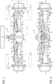
- Wheels 14, shown in dashed lines in FIG. 1 are coupled to axle 12. Wheels 14 of the vehicle are steerable and may be driven. Axle 12 may have a differential 30. Differential 30 is encased in a differential housing 32 and has an input shaft 34. Input shaft 34 transmits power from the vehicle engine to rear wheels 14.
- axle housings 38 Extending from the right and left sides of differential 30 are drive shaft housings 38.
- the left side of axle 12 includes the same components and is a mirror image of the right side.
- a tie rod extending along axle 12 is pivotally connected to arms 51 projecting from pivot assemblies 42, located on to the right and left of differential 30. Tie rod 53 maintains an angular relationship between wheels 14.
- Drive shaft housing 38 which encases axle shaft 36 has an outer wall 53 with a recess 54 disposed therein.
- Recess 54 which is configured to receive a portion of an actuator 52, extends into drive shaft housing 38 but not far enough into housing 38 as to interfere with axle shaft 36.
- a tip 56 of semi-conical recess 54 is located proximate pivot assembly 42, while a base 58 of recess 54 is located proximate differential housing 32. Recess 54 extends further into housing 38 at base 58 than at tip 56.
- a pivot assembly 42 pivotally couples drive shaft housing 38 to a wheel bearing support 44.
- Wheel bearing support 44 constitutes a stationary inner bearing race.
- a bearing assembly 46 is mounted between bearing support 44 and a wheel hub 47.
- Bearing assembly 46 enables rotation of a wheel hub 47 relative to bearing support 44.
- Wheel hub 47 is driven to rotate by a wheel drive shaft 48 via a planetary gear drive assembly 45 that receives input power from wheel drive shaft 48.
- the components of planetary gear drive assembly 45 are not shown in FIG. 4 , however, a suitable planetary gear set is shown in FIG. 13 .
- the planetary gear drive assembly 45 includes an internal gear disposed on the interior revolved surface of a wheel hub 47 such that rotation of wheel drive shaft 48 causes rotation of wheel hub 47. It should be understood that one wheel 14 is mounted to wheel hub 47.
- Pivot assembly 42 includes king pins 43 which pivotally couple support 44 to housing 38. Pins 43 enable wheel 14, coupled to wheel bearing support 44, to turn relative to drive shaft housing 38. Pivot assembly 42 houses an angle drive assembly 50. Angle drive assembly 50 is coupled to axle shaft 36 at an end opposite from MFD differential 30. Angle drive assembly 50 is also coupled to wheel drive shaft 48 of bearing support 44.
- Actuator 52 is disposed between and coupled to drive shaft housing 38 and a pivot arm/portion 51 of pivot assembly 42.
- Actuator 52 which may be a hydraulic cylinder, turns pivot assembly 42 relative to drive shaft housing 38.
- a portion of actuator 52 is located in recess 54 of drive shaft housing 38, enabling actuator 52 to move closer to axle shaft 36 during steering.
- Wheel 14 may pivot to the right and left at respective angle X (for example).
- the axle of FIGs. 1-4 is driven by power take off shafts that are powered by an internal combustion engine (for example) of the vehicle.
- the axle may be driven by a separate hydraulic motor.
- the hydraulic motor could be a vane motor, a gear motor, a gerotor motor, an axial plunger motor, or a radial piston motor, by way of example.
- the motor is not limited to being a hydraulic motor, and could be an electric motor, for example.
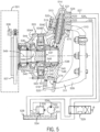
- axle 500 may be used with an agricultural vehicle. Unlike axle 12, the wheels connected to axle 500 are driven by a separate hydraulic motor as opposed to a power take off shaft.
- Axle assembly 500 generally includes a frame 509 mountable to the remaining portion of the axle (not shown), a hydraulic motor 503 comprising a three-part casing 504A-C as well as an output shaft 506, and a fixing flange 507 on which the ground contacting wheel 501 is fixed by bolts 508.
- Frame 509 includes two arms 510, 511. The end of the lower arm 511 is provided with a bore 512, and the end of the upper arm 510 is provided with a bore 513.
- a lower journal 518 and an upper journal 519 are introduced into the bores 512 and 513 and are fixed to the part 504C of the motor housing 503 by fasteners 520, and cooperate with rings 574 and 575, respectively, to carry out pivoting of the motor 503 and wheel 501 around the pivot axis 514.
- Wheel 501 may be steerable using a hydraulic actuator, such as the actuator 52 shown in FIG. 3 .
- the upper journal 519 is surmounted by an end cap 521 provided with three hydraulic connections 522, 523, 524 that are connected to three external conduits 525, 526, 527, respectively.
- the conduit 525 is connected to a reservoir 528.
- the conduits 526 and 527 are connected to a distributor 529 with three positions.
- a pump 530 has its suction duct 531 connected to the reservoir 528, and, its discharge duct 532 connected to the distributor 529.
- a conduit 533 connects the distributor 529 to the reservoir 528.
- the hydraulic motor 503 is of the radial piston type (and can vary as described above).
- Motor 503 comprises: rolling bearings 536 carrying out the rotational mounting of the shaft 506 relative to the casing 504A-C around an axis 549; a corrugated cam 537 formed by the internal periphery of the part 504B of the casing; an internal fluid distributor 538 with the various working chambers 539 each delimited by a piston 540 slidably mounted in a cylinder 541 formed in a cylinder block 542 integral with respect to the rotation of the shaft 506.
- the pistons are in abutment reaction on the cam 537 by means of rollers 543; and, an enclosure 544 delimited inside the casing 504A-C.
- the internal fluid distributor 538 comprises two chambers constituted by annular grooves 545, 546 for distributing fluid to two groups of conduits 547, 548 respectively, themselves in periodic communications with said working chambers 539.
- Axle 600 may be a rear axle or a front axle. Only one side of axle 600 is shown, however, the opposite side of axle 600 not shown in those figures is substantially similar to that which is shown. It should be understood while a ground contacting wheel 601 attached to axle 600 is hydraulically powered by a hydraulic motor 603 (like axle 500 of FIG. 5 ), axle 600 could be powered by a power take-off (PTO) shaft like the axle 12 of FIG. 1 . Thus, the details of axles 12 and 500 apply to the axle 600.
- PTO power take-off
- the partial axle 600 generally comprises a frame 610 having a C-shaped end including a lower arm 611 and an upper arm 612.
- a transversely extending passageway 614 is disposed in the frame 610.
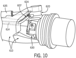
- An opening at the end of passageway 614 which is shown in FIGs. 6 and 10 , is disposed at an elevation between arms 611 and 612.
- the opening of passageway 614 faces hydraulic connections 624. Stated differently, the opening at the end of passageway 614 faces, is directly adjacent and/or is positioned in the direct vicinity of the hydraulic connections 624.
- hydraulic lines 607 that (ultimately) deliver fluid to motor 603, which drives wheel 601, are positioned within passageway 614. Positioning the hydraulic lines 607 within passageway 614 protects the lines 607 from damage by other components of the vehicle (as compared with externally routed lines), subjects the lines 607 to less bending which improves hydraulic efficiency, simplifies routing of the lines 607, and limits the accumulation of dirt and debris on those lines 607 (as compared with externally routed lines).
- lines 607 carry fluid to hydraulic motor 603 via a bearing assembly 620 and a manifold 644, however, it should be understood that it is contemplated that, according to a different embodiment, lines 607 could carry electrical current to motor 603 if motor 603 was an electric motor. Most of the aforementioned benefits of routing lines 607 within passageway 614 are applicable for an electrical motor and its current carrying lines.
- bearing assembly 617 is fixed to the free end of lower arm 611.
- Bearing assembly 617 includes a hollow cup-shaped cylindrical body and an axial thrust bearing 619 that is mounted to the top end of that body.
- the body of bearing assembly 617 is a stationary component, i.e., stationary with respect to frame 610.
- Bearing 619 is sandwiched between the body of the bearing assembly 617, and a surface of a steering knuckle 630.
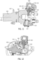
- bearing assembly 620 which may also be described as a turret, is fixed to the free end 622 of upper arm 612. As best shown in FIGs. 7 and 11 , bearing assembly 620 includes a cylindrical bearing body 621 including an upper end that is fixed to end 622 of upper arm 612 and a lower end that is mounted to steering knuckle 630 by an axial thrust bearing 626.
- the body 621 of bearing assembly 620 is a stationary component, i.e., stationary with respect to frame 610.
- steering knuckle 630 is configured to rotate about steering axis 623 relative to frame 610.
- Steering axis 623 is substantially orthogonal (or oblique to) drive axis 625.
- the body 621 of bearing 620 includes a series of three different flow passages 640 extending, respectively, from three different hydraulic connections 624. Hydraulic connections 624 and their respective flow passages 640 may not substantially differ in form, function and purpose from hydraulic connections 522-524 and their respective flow passages of FIG. 5 .
- the body 621 of bearing 620 is analogous to stationary end cap 521. Thus, the details of the flow passages described above with reference to FIG. 5 also apply to the flow passages within the bearing 620.
- the fluid channels 640 of bearing assembly 620 are fluidly connected to fluid channels 642 formed in steering knuckle 630.
- Knuckle 630 may be considered analogous to part 504C that is rotatable about axis 514 relative to end cap 521.
- the details of the flow passages described above with reference to FIG. 5 also apply to the flow passages within steering knuckle 630.
- the entire fluid flow diagram shown in FIG. 5 is applicable to axle 600.
- the fluid channels 642 formed in steering knuckle 630 are fluidly connected to fluid channels and passageways formed in a manifold 644 ( FIG. 12 ) that is connected to the exterior of steering knuckle 630.
- the fluid channels in manifold 644 are fluidly connected to fluid channels within motor 603. Introducing fluid into motor 603, causes rotation of an output shaft of motor 603 in the known manner.
- the output shaft of motor 603 is connected to a planetary gear drive assembly 650, like the assembly 45 of FIG. 4 .
- FIG. 13 and 15 those figures show a planetary gear drive (PGD) assembly 650.
- PGD assembly 650 includes a housing 652 that is mounted to knuckle 630, such that PGD assembly 650 pivots along with knuckle 630 about steering axis 623.
- PGD assembly 650 includes a shaft 654 that is non-rotatably connected to the output shaft of motor 603. Alternatively, shaft 654 may represent the output shaft of motor 603. Shaft 654 is non-rotatably connected to a sun gear 656.
- Sun gear 656 meshes with a series of planet gears 658 that are interconnected by a triangular-shaped carrier 660.
- the carrier 660 is bolted to an inner race 1407 (see FIG. 15 ).
- Inner race 1407 does not rotate about drive axis 625 along with the rotating components of PGD 650.
- the planet gears 658 are meshed with an internal gear 662 disposed on the interior revolved surface of housing 652. Rotation of internal gear 662 and consequent rotation of housing 652 about drive axis 625 causes rotation of the wheel 501 (not shown in these figures) that is bolted to the flange 627 of housing 652.
- Housing 652 constitutes at least part of a wheel hub and may be referred to herein as a wheel hub.
- PGD assembly 650 includes a bearing assembly 1401 including a cylindrical bearing carrier 1403 and a plurality of bearings 1405 arranged on an interior revolved surface of carrier 1403 that faces the inner race 1407.
- the inner race 1407 is bolted to knuckle 630, whereas, in the embodiment of FIGs. 6-13 , the inner race 1407 is integrated with knuckle 630', the significance of which will be described later.
- the gears of PGD assembly 650 operate in a well-known conventional manner to convert the rotational speed of the output shaft of the motor 603 to a lower rotational speed that is ultimately transmitted to the ground wheel 601.
- a hydraulic or pneumatic actuator 635 having a well-known piston and cylinder arrangement is connected to the pivot arm 631 of steering knuckle 630.
- Actuator 635 is analogous to the actuator 52 of FIG. 3 .
- extension and retraction of the piston within the cylinder of actuator 635 causes knuckle 630 to rotate about steering axis 623, which causes wheel 601 to rotate (like that shown in FIG. 3 ).
- wheel 601 turns along with knuckle 630, motor 603, PGD 650, and manifold 644, while the bodies of bearing assemblies 617 and 620 remain stationary.
- knuckle 630' also includes, among other features, a body having internal fluid channels 642 (described above), a pivot arm 631 that interfaces with the actuator 635, a cylindrical end 1409 that is mounted to PGD assembly 650, an upper bearing surface 1402 that interfaces with bearing assembly 620, and a lower bearing surface 1404 that interfaces with bearing assembly 617. Elements 631, 1409, 1402, and 1404 are joined by material webs.
- the entire body of knuckle 630' is a monolithic and unitary component, which may be a cast part, for example.
- the inner race 1407 is integrated with the body of knuckle 630'.
- a plurality of bearings 1405 are arranged on a surface of carrier 1403 that faces inner race 1407.
- One set of bearings 1405 engages the exterior revolved surface of race 1407, while the another set of bearings 1405 engages the exterior revolved surface of carrier 660 that is fixed to race 1407 by fasteners.
- Bearings 1405 may be in the form of tapered roller bearings, roller bearings, axial thrust bearings, conical bearings, ball bearings, radial bearings, needle bearings, bushings, and so forth.
- Integrating knuckle 630' with race 1407 reduces the number of fasteners (as compared with a design including separate knuckles and races), which leads to lower material costs, reduces the number of potential failure points, results in lower weight, and eases the assembly and installation process.
- the work vehicle described herein is not limited to any particular type of vehicle, and may be, for example, a combine, a tractor, a harvester, a beet harvester, a windrower, or even a passenger vehicle.
Landscapes
- Engineering & Computer Science (AREA)
- Chemical & Material Sciences (AREA)
- Combustion & Propulsion (AREA)
- Transportation (AREA)
- Mechanical Engineering (AREA)
- Motor Power Transmission Devices (AREA)
Abstract
An axle for a vehicle includes a transversely mounted axle housing (610) that is configured to support ground contacting wheels (601) of the vehicle. A wheel hub (652) is rotatably connected to the axle housing about a drive axis (625). The wheel hub is configured to be connected to one of the ground contacting wheels of the vehicle. A motor (603) is configured to rotate the wheel that is connected to the wheel hub. The axle housing includes a passageway (614) defined at least partially through the axle housing through which lines, conduits or cables (607) pass for connecting to the motor.
Description
- The invention is directed to a driven and/or steerable axle assembly for an agricultural vehicle.
- Work vehicles, such as combine harvesters, forage harvesters, windrowers, swathers, and the like have a front axle and a rear axle. The vehicle may be four-wheel drive or two-wheel drive. The rear wheels may be steerable. Described herein is an improved axle for an agricultural vehicle that may be both steerable and directly powered by either a power take-off shaft or a hydraulic motor.
- According to one aspect of the invention, an axle for a vehicle includes an axle housing that is configured to support ground contacting wheels of the vehicle. A wheel hub is rotatably connected to the axle housing about a drive axis. The wheel hub is configured to be connected to one of the ground contacting wheels of the vehicle. A motor is configured to rotate the wheel that is connected to the wheel hub. The axle housing includes a passageway defined at least partially through the axle housing through which lines, conduits or cables pass for connecting to the motor.
- The above-mentioned and other features and advantages of this invention, and the manner of attaining them, will become more apparent and the invention will be better understood by reference to the following description of an embodiment of the invention taken in conjunction with the accompanying drawings, wherein:
-
FIG. 1 is a top view of a drive axle of a vehicle, according to a first exemplary embodiment. -
FIG. 2 is a rear view of the axle taken generally along line 2-2 ofFIG. 1 . -
FIG. 3 is a top view of the right side of the axle shown taken generally along line 3-3 ofFIG. 1 and showing the wheel fully turned toward the right. -
FIG. 4 is a cross-section view of the right side of the axle shown inFIG. 2 taken along the lines 4-4. -
FIG. 5 is a cross-sectional view of the left side of a partial axle, according to a second exemplary embodiment. -
FIGs. 6-10 depict isometric views of the left side of a partial axle, according to a third exemplary embodiment. -
FIG. 11 depicts a cross-sectional view taken through the partial axle ofFIG. 9 . -
FIG. 12 depicts another cross-sectional view taken through the partial axle ofFIG. 9 . -
FIG. 13 is a rear view of the partial axle ofFIG. 6 with a cover omitted to reveal an internal planetary gear set. -
FIG. 14 depicts an isometric view of the left side of a partial axle, according to a fourth exemplary embodiment, wherein various components of the axle have been omitted. -
FIG. 15 depicts a cross-sectional view of the partial axle ofFIG. 14 . - Corresponding reference characters indicate corresponding parts throughout the several views. The exemplification set out herein illustrates embodiments of the invention, in one form, and such exemplification is not to be construed as limiting the scope of the invention in any manner.
- In the drawings, like numerals refer to like items, certain elements and features may be labeled or marked on a representative basis without each like element or feature necessarily being individually shown, labeled, or marked, and certain elements are labeled and marked in only some, but not all, of the drawing figures.
- The terms "longitudinal" and "transverse" are determined with reference to a fore-and-aft direction of the vehicle and are not to be construed as limiting.
- Turning now to
FIGs. 1-4 , as is described inU.S. Patent No. 6056081 anagricultural vehicle 10 includes a front axle coupled to front wheels and a rear axle coupled to rear wheels. Axle 12 and its wheels 14 depicted inFIG. 1 may represent the rear axle for the purposes of this disclosure. Alternatively,axle 12 may represent a front axle. An engine of the vehicle provides power through a transmission and a differential to drive wheels 14. - Wheels 14, shown in dashed lines in
FIG. 1 , are coupled toaxle 12. Wheels 14 of the vehicle are steerable and may be driven. Axle 12 may have adifferential 30. Differential 30 is encased in adifferential housing 32 and has aninput shaft 34.Input shaft 34 transmits power from the vehicle engine to rear wheels 14. - Extending from the right and left sides of
differential 30 are driveshaft housings 38. For purposes of simplicity, the remainder of the description ofrear axle 12 will focus on the right side. The left side ofaxle 12 includes the same components and is a mirror image of the right side. - A tie rod extending along
axle 12 is pivotally connected toarms 51 projecting frompivot assemblies 42, located on to the right and left ofdifferential 30. Tierod 53 maintains an angular relationship between wheels 14. -
Drive shaft housing 38 which encasesaxle shaft 36 has anouter wall 53 with arecess 54 disposed therein.Recess 54, which is configured to receive a portion of anactuator 52, extends intodrive shaft housing 38 but not far enough intohousing 38 as to interfere withaxle shaft 36. Atip 56 ofsemi-conical recess 54 is locatedproximate pivot assembly 42, while abase 58 ofrecess 54 is located proximatedifferential housing 32.Recess 54 extends further intohousing 38 atbase 58 than attip 56. - A
pivot assembly 42 pivotally couples driveshaft housing 38 to awheel bearing support 44.Wheel bearing support 44 constitutes a stationary inner bearing race. Abearing assembly 46 is mounted betweenbearing support 44 and awheel hub 47.Bearing assembly 46 enables rotation of awheel hub 47 relative to bearingsupport 44.Wheel hub 47 is driven to rotate by awheel drive shaft 48 via a planetarygear drive assembly 45 that receives input power fromwheel drive shaft 48. The components of planetarygear drive assembly 45 are not shown inFIG. 4 , however, a suitable planetary gear set is shown inFIG. 13 . The planetarygear drive assembly 45 includes an internal gear disposed on the interior revolved surface of awheel hub 47 such that rotation ofwheel drive shaft 48 causes rotation ofwheel hub 47. It should be understood that one wheel 14 is mounted towheel hub 47. -
Pivot assembly 42 includesking pins 43 which pivotally couple support 44 to housing 38.Pins 43 enable wheel 14, coupled towheel bearing support 44, to turn relative to driveshaft housing 38.Pivot assembly 42 houses anangle drive assembly 50.Angle drive assembly 50 is coupled toaxle shaft 36 at an end opposite fromMFD differential 30.Angle drive assembly 50 is also coupled towheel drive shaft 48 ofbearing support 44. -
Actuator 52 is disposed between and coupled to driveshaft housing 38 and a pivot arm/portion 51 ofpivot assembly 42.Actuator 52, which may be a hydraulic cylinder, turnspivot assembly 42 relative to driveshaft housing 38. At the turning angle which occurs as a result of the orientation ofassembly 42 relative tohousing 38 as shown inFIG. 3 , a portion ofactuator 52 is located inrecess 54 ofdrive shaft housing 38, enablingactuator 52 to move closer toaxle shaft 36 during steering. Wheel 14 may pivot to the right and left at respective angle X (for example). - The axle of
FIGs. 1-4 is driven by power take off shafts that are powered by an internal combustion engine (for example) of the vehicle. According to a different embodiment, the axle may be driven by a separate hydraulic motor. The hydraulic motor could be a vane motor, a gear motor, a gerotor motor, an axial plunger motor, or a radial piston motor, by way of example. Also, as noted below, the motor is not limited to being a hydraulic motor, and could be an electric motor, for example. - Turning now to
FIG. 5 , as is described inFrench Patent No. 2693154 axle 12, axle 500 may be used with an agricultural vehicle. Unlikeaxle 12, the wheels connected to axle 500 are driven by a separate hydraulic motor as opposed to a power take off shaft. - Axle assembly 500 generally includes a
frame 509 mountable to the remaining portion of the axle (not shown), ahydraulic motor 503 comprising a three-part casing 504A-C as well as anoutput shaft 506, and a fixingflange 507 on which theground contacting wheel 501 is fixed bybolts 508.Frame 509 includes twoarms lower arm 511 is provided with abore 512, and the end of theupper arm 510 is provided with abore 513. Alower journal 518 and anupper journal 519 are introduced into thebores part 504C of themotor housing 503 byfasteners 520, and cooperate withrings motor 503 andwheel 501 around thepivot axis 514.Wheel 501 may be steerable using a hydraulic actuator, such as theactuator 52 shown inFIG. 3 . - The
upper journal 519 is surmounted by anend cap 521 provided with threehydraulic connections external conduits conduit 525 is connected to areservoir 528. Theconduits distributor 529 with three positions. Apump 530 has itssuction duct 531 connected to thereservoir 528, and, itsdischarge duct 532 connected to thedistributor 529. Aconduit 533 connects thedistributor 529 to thereservoir 528. Aduct 534, on which adischarge valve 535 is arranged, connects the discharge duct to thereservoir 528. - The
hydraulic motor 503 is of the radial piston type (and can vary as described above).Motor 503 comprises: rollingbearings 536 carrying out the rotational mounting of theshaft 506 relative to thecasing 504A-C around anaxis 549; acorrugated cam 537 formed by the internal periphery of thepart 504B of the casing; aninternal fluid distributor 538 with the various workingchambers 539 each delimited by apiston 540 slidably mounted in acylinder 541 formed in acylinder block 542 integral with respect to the rotation of theshaft 506. The pistons are in abutment reaction on thecam 537 by means ofrollers 543; and, anenclosure 544 delimited inside thecasing 504A-C. Theinternal fluid distributor 538 comprises two chambers constituted byannular grooves conduits chambers 539. - Turning now to
FIGs. 6-10 , anotherpartial axle 600 is shown.Axle 600 may be a rear axle or a front axle. Only one side ofaxle 600 is shown, however, the opposite side ofaxle 600 not shown in those figures is substantially similar to that which is shown. It should be understood while aground contacting wheel 601 attached toaxle 600 is hydraulically powered by a hydraulic motor 603 (like axle 500 ofFIG. 5 ),axle 600 could be powered by a power take-off (PTO) shaft like theaxle 12 ofFIG. 1 . Thus, the details ofaxles 12 and 500 apply to theaxle 600. - The
partial axle 600 generally comprises aframe 610 having a C-shaped end including alower arm 611 and anupper arm 612. A transversely extendingpassageway 614 is disposed in theframe 610. An opening at the end ofpassageway 614, which is shown inFIGs. 6 and10 , is disposed at an elevation betweenarms passageway 614 faceshydraulic connections 624. Stated differently, the opening at the end ofpassageway 614 faces, is directly adjacent and/or is positioned in the direct vicinity of thehydraulic connections 624. - In an assembled form of the
axle 600,hydraulic lines 607 that (ultimately) deliver fluid tomotor 603, which driveswheel 601, are positioned withinpassageway 614. Positioning thehydraulic lines 607 withinpassageway 614 protects thelines 607 from damage by other components of the vehicle (as compared with externally routed lines), subjects thelines 607 to less bending which improves hydraulic efficiency, simplifies routing of thelines 607, and limits the accumulation of dirt and debris on those lines 607 (as compared with externally routed lines). - According to this embodiment, lines 607 (ultimately) carry fluid to
hydraulic motor 603 via abearing assembly 620 and a manifold 644, however, it should be understood that it is contemplated that, according to a different embodiment,lines 607 could carry electrical current tomotor 603 ifmotor 603 was an electric motor. Most of the aforementioned benefits of routinglines 607 withinpassageway 614 are applicable for an electrical motor and its current carrying lines. - As best shown in
FIG. 11 , a bearingassembly 617 is fixed to the free end oflower arm 611.Bearing assembly 617 includes a hollow cup-shaped cylindrical body and an axial thrust bearing 619 that is mounted to the top end of that body. The body of bearingassembly 617 is a stationary component, i.e., stationary with respect toframe 610. Bearing 619 is sandwiched between the body of the bearingassembly 617, and a surface of asteering knuckle 630. - The bearing
assembly 620, which may also be described as a turret, is fixed to thefree end 622 ofupper arm 612. As best shown inFIGs. 7 and11 , bearingassembly 620 includes a cylindrical bearing body 621 including an upper end that is fixed to end 622 ofupper arm 612 and a lower end that is mounted tosteering knuckle 630 by anaxial thrust bearing 626. The body 621 of bearingassembly 620 is a stationary component, i.e., stationary with respect toframe 610. By virtue of thebearings knuckle 630 is configured to rotate about steeringaxis 623 relative to frame 610.Steering axis 623 is substantially orthogonal (or oblique to) driveaxis 625. - Although axial thrust bearing have been mentioned thus far, it should be understood that other bearings types are envisioned, such as conical bearings, radial bearings, needle bearings, bushings, and so forth.
- The body 621 of bearing 620 includes a series of three
different flow passages 640 extending, respectively, from three differenthydraulic connections 624.Hydraulic connections 624 and theirrespective flow passages 640 may not substantially differ in form, function and purpose from hydraulic connections 522-524 and their respective flow passages ofFIG. 5 . The body 621 of bearing 620 is analogous tostationary end cap 521. Thus, the details of the flow passages described above with reference toFIG. 5 also apply to the flow passages within thebearing 620. - Turning now to
FIGs. 8-12 , thefluid channels 640 of bearingassembly 620 are fluidly connected tofluid channels 642 formed insteering knuckle 630.Knuckle 630 may be considered analogous topart 504C that is rotatable aboutaxis 514 relative to endcap 521. Thus, the details of the flow passages described above with reference toFIG. 5 also apply to the flow passages withinsteering knuckle 630. Generally speaking, the entire fluid flow diagram shown inFIG. 5 is applicable toaxle 600. - The
fluid channels 642 formed insteering knuckle 630 are fluidly connected to fluid channels and passageways formed in a manifold 644 (FIG. 12 ) that is connected to the exterior ofsteering knuckle 630. The fluid channels inmanifold 644 are fluidly connected to fluid channels withinmotor 603. Introducing fluid intomotor 603, causes rotation of an output shaft ofmotor 603 in the known manner. The output shaft ofmotor 603 is connected to a planetarygear drive assembly 650, like theassembly 45 ofFIG. 4 . - Turning now to
FIG. 13 and15 , those figures show a planetary gear drive (PGD)assembly 650. It is noted at the outset that even thoughFIGs. 13 and15 depict different embodiments, those embodiments have thesame PGD assembly 650.PGD assembly 650 includes ahousing 652 that is mounted to knuckle 630, such thatPGD assembly 650 pivots along withknuckle 630 about steeringaxis 623.PGD assembly 650 includes ashaft 654 that is non-rotatably connected to the output shaft ofmotor 603. Alternatively,shaft 654 may represent the output shaft ofmotor 603.Shaft 654 is non-rotatably connected to asun gear 656.Sun gear 656 meshes with a series of planet gears 658 that are interconnected by a triangular-shapedcarrier 660. Thecarrier 660 is bolted to an inner race 1407 (seeFIG. 15 ).Inner race 1407 does not rotate aboutdrive axis 625 along with the rotating components ofPGD 650. The planet gears 658 are meshed with aninternal gear 662 disposed on the interior revolved surface ofhousing 652. Rotation ofinternal gear 662 and consequent rotation ofhousing 652 aboutdrive axis 625 causes rotation of the wheel 501 (not shown in these figures) that is bolted to theflange 627 ofhousing 652.Housing 652 constitutes at least part of a wheel hub and may be referred to herein as a wheel hub. -
PGD assembly 650 includes a bearing assembly 1401 including a cylindrical bearing carrier 1403 and a plurality ofbearings 1405 arranged on an interior revolved surface of carrier 1403 that faces theinner race 1407. In the embodiment ofFIGs. 6-13 , theinner race 1407 is bolted to knuckle 630, whereas, in the embodiment ofFIGs. 6-13 , theinner race 1407 is integrated with knuckle 630', the significance of which will be described later. - The gears of
PGD assembly 650 operate in a well-known conventional manner to convert the rotational speed of the output shaft of themotor 603 to a lower rotational speed that is ultimately transmitted to theground wheel 601. - Turning now to
FIGs. 7 and10 , a hydraulic orpneumatic actuator 635 having a well-known piston and cylinder arrangement is connected to thepivot arm 631 ofsteering knuckle 630.Actuator 635 is analogous to theactuator 52 ofFIG. 3 . In operation, extension and retraction of the piston within the cylinder ofactuator 635 causes knuckle 630 to rotate about steeringaxis 623, which causeswheel 601 to rotate (like that shown inFIG. 3 ). It should be understood thatknuckle 630 does not rotate aboutaxis 625. It should be understood thatwheel 601 turns along withknuckle 630,motor 603,PGD 650, andmanifold 644, while the bodies of bearingassemblies - Turning now to
FIGs. 14 and15 , depicted in those figures is an alternative steering knuckle 630'. Likeknuckle 630, knuckle 630' also includes, among other features, a body having internal fluid channels 642 (described above), apivot arm 631 that interfaces with theactuator 635, acylindrical end 1409 that is mounted toPGD assembly 650, anupper bearing surface 1402 that interfaces with bearingassembly 620, and alower bearing surface 1404 that interfaces with bearingassembly 617.Elements - The differences between the
knuckles 630 and 630' will be described hereinafter. The entire body of knuckle 630' is a monolithic and unitary component, which may be a cast part, for example. In the knuckle 630', theinner race 1407 is integrated with the body of knuckle 630'. A plurality ofbearings 1405 are arranged on a surface of carrier 1403 that facesinner race 1407. One set ofbearings 1405 engages the exterior revolved surface ofrace 1407, while the another set ofbearings 1405 engages the exterior revolved surface ofcarrier 660 that is fixed torace 1407 by fasteners.Bearings 1405 may be in the form of tapered roller bearings, roller bearings, axial thrust bearings, conical bearings, ball bearings, radial bearings, needle bearings, bushings, and so forth. - Integrating knuckle 630' with
race 1407 reduces the number of fasteners (as compared with a design including separate knuckles and races), which leads to lower material costs, reduces the number of potential failure points, results in lower weight, and eases the assembly and installation process. - It should be understood that the work vehicle described herein is not limited to any particular type of vehicle, and may be, for example, a combine, a tractor, a harvester, a beet harvester, a windrower, or even a passenger vehicle.
- This application is intended to cover any variations, uses, or adaptations of the invention using its general principles. Further, this application is intended to cover such departures from the present disclosure as come within known or customary practice in the art to which this invention pertains and which fall within the limits of the appended claims.
Claims (14)
- An axle for a vehicle, said axle comprising:an axle housing (610) that is configured to support ground contacting wheels (601) of the vehicle;a wheel hub (652) that is rotatably connected to the axle housing about a drive axis (625), wherein the wheel hub is configured to be connected to one of the ground contacting wheels of the vehicle; anda motor (603) configured to rotate said one of the wheels that is connected to the wheel hub;characterized in that the axle housing includes a passageway (614) defined at least partially through the axle housing through which lines (607) pass for connecting to the motor.
- The axle of claim 1, further comprising the lines (607) routed within the passageway.
- The axle of either claim 1 or 2, wherein the axle housing (610) includes a main body (610), an upper arm (612) branching from the main body for connection to the wheel hub, and a lower arm (611) branching from the main body for connection to the wheel hub, and wherein the passageway (614) is formed in the main body.
- The axle of claim 3, further comprising an upper bearing assembly (620) connecting the upper arm (612) to the wheel hub (652), and a lower bearing assembly (617) connecting the lower arm to the wheel hub, wherein the upper and lower bearing assemblies are configured to permit rotation of the wheel hub about a steering axis (623).
- The axle of claim 4, further comprising a steering knuckle (630, 630') that is mounted between the upper and lower bearing assemblies (620, 617), and is also mounted between the upper and lower arms (612, 611), and wherein the steering knuckle is rotatable about the steering axis relative to the axle housing and a stationary component (621) of each bearing assembly (620, 617).
- The axle of claim 5, wherein the motor (603) and wheel hub (652) are mounted to the steering knuckle (630) and rotate along with the steering knuckle about the steering axis.
- The axle of either claim 5 or 6, further comprising an actuator (635) mounted to the steering knuckle for rotating the steering knuckle and the motor about the steering axis.
- The axle of one of claims 4-7, wherein one of the bearing assemblies (620) includes a bearing body (621) having at least one internal fluid passage (640), and a bearing (626) that is mounted to the bearing body (621) for accommodating rotation of the wheel hub (652) about the steering axis.
- The axle of claim 8, wherein the at least one internal fluid passage (640) of the bearing body terminates at a connector (624) that is mounted to the body (621).
- The axle of claim 9, wherein the connector (624) is positioned directly adjacent to an opening of the passageway (614) that is defined in the axle housing.
- The axle of one of claims 8-10, wherein the steering knuckle (630, 630') is rotatably connected to the bearing body (621) about the steering axis (623), and wherein said steering knuckle includes an internal fluid passage (642) that is fluidly connected to the at least one internal fluid passage (640) of the bearing body (621).
- The axle of one of claims 9-11, wherein the motor (603) is a hydraulic motor that is fluidly connected to the internal fluid passage (642) of said steering knuckle (630, 630') by an additional fluid line (644).
- The axle of any one of the preceding claims, further comprising another wheel hub (652) connected to the axle housing (610), wherein the wheel hubs are connected to opposing sides of the axle housing.
- A combine harvester (10), forage harvester, windrower or swather comprising the axle of any one of the preceding claims.
Priority Applications (1)
| Application Number | Priority Date | Filing Date | Title |
|---|---|---|---|
| EP23157847.7A EP4420905A1 (en) | 2023-02-21 | 2023-02-21 | Axle housing for agricultural vehicle with internal passageway for routing conduits |
Applications Claiming Priority (1)
| Application Number | Priority Date | Filing Date | Title |
|---|---|---|---|
| EP23157847.7A EP4420905A1 (en) | 2023-02-21 | 2023-02-21 | Axle housing for agricultural vehicle with internal passageway for routing conduits |
Publications (1)
| Publication Number | Publication Date |
|---|---|
| EP4420905A1 true EP4420905A1 (en) | 2024-08-28 |
Family
ID=85321098
Family Applications (1)
| Application Number | Title | Priority Date | Filing Date |
|---|---|---|---|
| EP23157847.7A Pending EP4420905A1 (en) | 2023-02-21 | 2023-02-21 | Axle housing for agricultural vehicle with internal passageway for routing conduits |
Country Status (1)
| Country | Link |
|---|---|
| EP (1) | EP4420905A1 (en) |
Citations (5)
| Publication number | Priority date | Publication date | Assignee | Title |
|---|---|---|---|---|
| FR2693154A1 (en) | 1992-11-09 | 1994-01-07 | Poclain Hydraulics Sa | Hydraulic motor and pivot mount for direct drive to automobile wheel - has pressurised fluid motor with stator pivotably mounted on frame and rotor rotatively mounted w.r.t stator, with stator having three internal chambers, and motor including unique rotating joint |
| US6056081A (en) | 1997-10-16 | 2000-05-02 | Case Corporation | Mechanical front wheel drive axle for improved steering |
| US20100225157A1 (en) * | 2009-03-05 | 2010-09-09 | Tuthill Corporation | Spindle with hydraulic passage arrangement and method of manufacture |
| US10710654B2 (en) * | 2017-01-10 | 2020-07-14 | New Heights, Llc | Hydraulic drive system |
| US20210108608A1 (en) * | 2018-04-25 | 2021-04-15 | Poclain Hydraulics Industrie | Hydraulic arrangement for a steered wheel of a vehicle |
-
2023
- 2023-02-21 EP EP23157847.7A patent/EP4420905A1/en active Pending
Patent Citations (5)
| Publication number | Priority date | Publication date | Assignee | Title |
|---|---|---|---|---|
| FR2693154A1 (en) | 1992-11-09 | 1994-01-07 | Poclain Hydraulics Sa | Hydraulic motor and pivot mount for direct drive to automobile wheel - has pressurised fluid motor with stator pivotably mounted on frame and rotor rotatively mounted w.r.t stator, with stator having three internal chambers, and motor including unique rotating joint |
| US6056081A (en) | 1997-10-16 | 2000-05-02 | Case Corporation | Mechanical front wheel drive axle for improved steering |
| US20100225157A1 (en) * | 2009-03-05 | 2010-09-09 | Tuthill Corporation | Spindle with hydraulic passage arrangement and method of manufacture |
| US10710654B2 (en) * | 2017-01-10 | 2020-07-14 | New Heights, Llc | Hydraulic drive system |
| US20210108608A1 (en) * | 2018-04-25 | 2021-04-15 | Poclain Hydraulics Industrie | Hydraulic arrangement for a steered wheel of a vehicle |
Similar Documents
| Publication | Publication Date | Title |
|---|---|---|
| US7950483B2 (en) | Wheel assembly with in-wheel motor | |
| EP1847441B1 (en) | Hydrostatic transaxle | |
| US20220381325A1 (en) | Bearing support for parallel electric axle gear assembly | |
| JP2623062B2 (en) | Hydraulic axial piston pump | |
| US7022039B2 (en) | Lubrication system for planetary transmission | |
| US20130333959A1 (en) | Steering axle for agricultural vehicles | |
| EP1348589A2 (en) | A carrier assembly for a drive axle | |
| US8122987B2 (en) | Vehicle having a wheel assembly with an in-wheel motor | |
| US10591037B2 (en) | Drive axle system having a planetary interaxle differential unit | |
| US6688417B2 (en) | Axial piston unit for integrated wheel hub | |
| US12291094B2 (en) | Stepped planetary single bearing carrier support | |
| EP4420958A1 (en) | Steering knuckle for agricultural vehicle | |
| US7240759B2 (en) | Transmission case housing a transmission mechanism for transmitting power to dirigible wheels | |
| US4896740A (en) | Wheel bearing support | |
| CN117450230A (en) | Axle assembly having an inter-axle differential unit | |
| US20070015619A1 (en) | Wheel motor device | |
| EP0911203B1 (en) | Mechanical front wheel axle for improved steering | |
| US20020155917A1 (en) | Axle assembly | |
| US6485389B1 (en) | Mechanical differential gear assembly | |
| US4609065A (en) | Wheel drive structure for agricultural tractor | |
| US20260049652A1 (en) | Power transmission device | |
| JP2535022B2 (en) | HST integrated axle drive | |
| EP0116763B1 (en) | Hydrostatic transaxle assembly | |
| US11408486B2 (en) | Planetary gear device and compound planetary gear device | |
| JPH10100701A (en) | Power transmission device for four-wheel drive vehicle |
Legal Events
| Date | Code | Title | Description |
|---|---|---|---|
| PUAI | Public reference made under article 153(3) epc to a published international application that has entered the european phase |
Free format text: ORIGINAL CODE: 0009012 |
|
| STAA | Information on the status of an ep patent application or granted ep patent |
Free format text: STATUS: THE APPLICATION HAS BEEN PUBLISHED |
|
| AK | Designated contracting states |
Kind code of ref document: A1 Designated state(s): AL AT BE BG CH CY CZ DE DK EE ES FI FR GB GR HR HU IE IS IT LI LT LU LV MC ME MK MT NL NO PL PT RO RS SE SI SK SM TR |
|
| STAA | Information on the status of an ep patent application or granted ep patent |
Free format text: STATUS: REQUEST FOR EXAMINATION WAS MADE |
|
| 17P | Request for examination filed |
Effective date: 20250228 |