EP4420898A1 - Heavy duty tire - Google Patents
Heavy duty tire Download PDFInfo
- Publication number
- EP4420898A1 EP4420898A1 EP24154478.2A EP24154478A EP4420898A1 EP 4420898 A1 EP4420898 A1 EP 4420898A1 EP 24154478 A EP24154478 A EP 24154478A EP 4420898 A1 EP4420898 A1 EP 4420898A1
- Authority
- EP
- European Patent Office
- Prior art keywords
- groove
- circumferential
- main
- sipe
- lateral
- Prior art date
- Legal status (The legal status is an assumption and is not a legal conclusion. Google has not performed a legal analysis and makes no representation as to the accuracy of the status listed.)
- Pending
Links
Images







Classifications
-
- B—PERFORMING OPERATIONS; TRANSPORTING
- B60—VEHICLES IN GENERAL
- B60C—VEHICLE TYRES; TYRE INFLATION; TYRE CHANGING; CONNECTING VALVES TO INFLATABLE ELASTIC BODIES IN GENERAL; DEVICES OR ARRANGEMENTS RELATED TO TYRES
- B60C11/00—Tyre tread bands; Tread patterns; Anti-skid inserts
- B60C11/03—Tread patterns
- B60C11/0306—Patterns comprising block rows or discontinuous ribs
-
- B—PERFORMING OPERATIONS; TRANSPORTING
- B60—VEHICLES IN GENERAL
- B60C—VEHICLE TYRES; TYRE INFLATION; TYRE CHANGING; CONNECTING VALVES TO INFLATABLE ELASTIC BODIES IN GENERAL; DEVICES OR ARRANGEMENTS RELATED TO TYRES
- B60C11/00—Tyre tread bands; Tread patterns; Anti-skid inserts
- B60C11/03—Tread patterns
- B60C11/032—Patterns comprising isolated recesses
- B60C11/0323—Patterns comprising isolated recesses tread comprising channels under the tread surface, e.g. for draining water
-
- B—PERFORMING OPERATIONS; TRANSPORTING
- B60—VEHICLES IN GENERAL
- B60C—VEHICLE TYRES; TYRE INFLATION; TYRE CHANGING; CONNECTING VALVES TO INFLATABLE ELASTIC BODIES IN GENERAL; DEVICES OR ARRANGEMENTS RELATED TO TYRES
- B60C11/00—Tyre tread bands; Tread patterns; Anti-skid inserts
- B60C11/03—Tread patterns
- B60C11/12—Tread patterns characterised by the use of narrow slits or incisions, e.g. sipes
- B60C11/1204—Tread patterns characterised by the use of narrow slits or incisions, e.g. sipes with special shape of the sipe
- B60C11/1218—Three-dimensional shape with regard to depth and extending direction
-
- B—PERFORMING OPERATIONS; TRANSPORTING
- B60—VEHICLES IN GENERAL
- B60C—VEHICLE TYRES; TYRE INFLATION; TYRE CHANGING; CONNECTING VALVES TO INFLATABLE ELASTIC BODIES IN GENERAL; DEVICES OR ARRANGEMENTS RELATED TO TYRES
- B60C11/00—Tyre tread bands; Tread patterns; Anti-skid inserts
- B60C11/03—Tread patterns
- B60C11/12—Tread patterns characterised by the use of narrow slits or incisions, e.g. sipes
- B60C11/1236—Tread patterns characterised by the use of narrow slits or incisions, e.g. sipes with special arrangements in the tread pattern
- B60C11/125—Tread patterns characterised by the use of narrow slits or incisions, e.g. sipes with special arrangements in the tread pattern arranged at the groove bottom
-
- B—PERFORMING OPERATIONS; TRANSPORTING
- B60—VEHICLES IN GENERAL
- B60C—VEHICLE TYRES; TYRE INFLATION; TYRE CHANGING; CONNECTING VALVES TO INFLATABLE ELASTIC BODIES IN GENERAL; DEVICES OR ARRANGEMENTS RELATED TO TYRES
- B60C11/00—Tyre tread bands; Tread patterns; Anti-skid inserts
- B60C11/03—Tread patterns
- B60C11/12—Tread patterns characterised by the use of narrow slits or incisions, e.g. sipes
- B60C11/1259—Depth of the sipe
-
- B—PERFORMING OPERATIONS; TRANSPORTING
- B60—VEHICLES IN GENERAL
- B60C—VEHICLE TYRES; TYRE INFLATION; TYRE CHANGING; CONNECTING VALVES TO INFLATABLE ELASTIC BODIES IN GENERAL; DEVICES OR ARRANGEMENTS RELATED TO TYRES
- B60C11/00—Tyre tread bands; Tread patterns; Anti-skid inserts
- B60C11/03—Tread patterns
- B60C11/12—Tread patterns characterised by the use of narrow slits or incisions, e.g. sipes
- B60C11/1272—Width of the sipe
- B60C11/1281—Width of the sipe different within the same sipe, i.e. enlarged width portion at sipe bottom or along its length
-
- B—PERFORMING OPERATIONS; TRANSPORTING
- B60—VEHICLES IN GENERAL
- B60C—VEHICLE TYRES; TYRE INFLATION; TYRE CHANGING; CONNECTING VALVES TO INFLATABLE ELASTIC BODIES IN GENERAL; DEVICES OR ARRANGEMENTS RELATED TO TYRES
- B60C11/00—Tyre tread bands; Tread patterns; Anti-skid inserts
- B60C11/03—Tread patterns
- B60C2011/0337—Tread patterns characterised by particular design features of the pattern
- B60C2011/0339—Grooves
- B60C2011/0341—Circumferential grooves
-
- B—PERFORMING OPERATIONS; TRANSPORTING
- B60—VEHICLES IN GENERAL
- B60C—VEHICLE TYRES; TYRE INFLATION; TYRE CHANGING; CONNECTING VALVES TO INFLATABLE ELASTIC BODIES IN GENERAL; DEVICES OR ARRANGEMENTS RELATED TO TYRES
- B60C11/00—Tyre tread bands; Tread patterns; Anti-skid inserts
- B60C11/03—Tread patterns
- B60C2011/0337—Tread patterns characterised by particular design features of the pattern
- B60C2011/0339—Grooves
- B60C2011/0341—Circumferential grooves
- B60C2011/0346—Circumferential grooves with zigzag shape
-
- B—PERFORMING OPERATIONS; TRANSPORTING
- B60—VEHICLES IN GENERAL
- B60C—VEHICLE TYRES; TYRE INFLATION; TYRE CHANGING; CONNECTING VALVES TO INFLATABLE ELASTIC BODIES IN GENERAL; DEVICES OR ARRANGEMENTS RELATED TO TYRES
- B60C11/00—Tyre tread bands; Tread patterns; Anti-skid inserts
- B60C11/03—Tread patterns
- B60C2011/0337—Tread patterns characterised by particular design features of the pattern
- B60C2011/0339—Grooves
- B60C2011/0341—Circumferential grooves
- B60C2011/0348—Narrow grooves, i.e. having a width of less than 4 mm
-
- B—PERFORMING OPERATIONS; TRANSPORTING
- B60—VEHICLES IN GENERAL
- B60C—VEHICLE TYRES; TYRE INFLATION; TYRE CHANGING; CONNECTING VALVES TO INFLATABLE ELASTIC BODIES IN GENERAL; DEVICES OR ARRANGEMENTS RELATED TO TYRES
- B60C11/00—Tyre tread bands; Tread patterns; Anti-skid inserts
- B60C11/03—Tread patterns
- B60C2011/0337—Tread patterns characterised by particular design features of the pattern
- B60C2011/0339—Grooves
- B60C2011/0341—Circumferential grooves
- B60C2011/0353—Circumferential grooves characterised by width
-
- B—PERFORMING OPERATIONS; TRANSPORTING
- B60—VEHICLES IN GENERAL
- B60C—VEHICLE TYRES; TYRE INFLATION; TYRE CHANGING; CONNECTING VALVES TO INFLATABLE ELASTIC BODIES IN GENERAL; DEVICES OR ARRANGEMENTS RELATED TO TYRES
- B60C11/00—Tyre tread bands; Tread patterns; Anti-skid inserts
- B60C11/03—Tread patterns
- B60C2011/0337—Tread patterns characterised by particular design features of the pattern
- B60C2011/0339—Grooves
- B60C2011/0341—Circumferential grooves
- B60C2011/0355—Circumferential grooves characterised by depth
-
- B—PERFORMING OPERATIONS; TRANSPORTING
- B60—VEHICLES IN GENERAL
- B60C—VEHICLE TYRES; TYRE INFLATION; TYRE CHANGING; CONNECTING VALVES TO INFLATABLE ELASTIC BODIES IN GENERAL; DEVICES OR ARRANGEMENTS RELATED TO TYRES
- B60C11/00—Tyre tread bands; Tread patterns; Anti-skid inserts
- B60C11/03—Tread patterns
- B60C2011/0337—Tread patterns characterised by particular design features of the pattern
- B60C2011/0339—Grooves
- B60C2011/0358—Lateral grooves, i.e. having an angle of 45 to 90 degees to the equatorial plane
- B60C2011/0362—Shallow grooves, i.e. having a depth of less than 50% of other grooves
-
- B—PERFORMING OPERATIONS; TRANSPORTING
- B60—VEHICLES IN GENERAL
- B60C—VEHICLE TYRES; TYRE INFLATION; TYRE CHANGING; CONNECTING VALVES TO INFLATABLE ELASTIC BODIES IN GENERAL; DEVICES OR ARRANGEMENTS RELATED TO TYRES
- B60C11/00—Tyre tread bands; Tread patterns; Anti-skid inserts
- B60C11/03—Tread patterns
- B60C2011/0337—Tread patterns characterised by particular design features of the pattern
- B60C2011/0339—Grooves
- B60C2011/0358—Lateral grooves, i.e. having an angle of 45 to 90 degees to the equatorial plane
- B60C2011/0367—Lateral grooves, i.e. having an angle of 45 to 90 degees to the equatorial plane characterised by depth
-
- B—PERFORMING OPERATIONS; TRANSPORTING
- B60—VEHICLES IN GENERAL
- B60C—VEHICLE TYRES; TYRE INFLATION; TYRE CHANGING; CONNECTING VALVES TO INFLATABLE ELASTIC BODIES IN GENERAL; DEVICES OR ARRANGEMENTS RELATED TO TYRES
- B60C11/00—Tyre tread bands; Tread patterns; Anti-skid inserts
- B60C11/03—Tread patterns
- B60C11/12—Tread patterns characterised by the use of narrow slits or incisions, e.g. sipes
- B60C11/1204—Tread patterns characterised by the use of narrow slits or incisions, e.g. sipes with special shape of the sipe
- B60C2011/1213—Tread patterns characterised by the use of narrow slits or incisions, e.g. sipes with special shape of the sipe sinusoidal or zigzag at the tread surface
-
- B—PERFORMING OPERATIONS; TRANSPORTING
- B60—VEHICLES IN GENERAL
- B60C—VEHICLE TYRES; TYRE INFLATION; TYRE CHANGING; CONNECTING VALVES TO INFLATABLE ELASTIC BODIES IN GENERAL; DEVICES OR ARRANGEMENTS RELATED TO TYRES
- B60C2200/00—Tyres specially adapted for particular applications
- B60C2200/06—Tyres specially adapted for particular applications for heavy duty vehicles
Definitions
- the present invention relates to a heavy duty tire. Specifically, the present invention relates to a heavy duty tire in which a block pattern is employed as a tread pattern.
- An object of the present invention is to provide a heavy duty tire that can have improved uneven wear resistance and can suppress deterioration in appearance quality and traction performance due to progress of wear.
- a tire according to the present invention is a heavy duty tire including a tread having a tread surface configured to come into contact with a road surface.
- the tread has a plurality of circumferential grooves continuously extending in a circumferential direction.
- the plurality of circumferential grooves divide the tread into a plurality of land portions aligned in an axial direction.
- the plurality of land portions include a plurality of main land portions each located between the adjacent circumferential grooves.
- Each of the main land portions has a plurality of main lateral grooves connecting the adjacent circumferential grooves.
- the plurality of main lateral grooves divide the main land portion into a plurality of main blocks aligned in the circumferential direction.
- Each of the main lateral grooves formed on the main land portion is located at a portion where the adjacent circumferential grooves are close to each other.
- Each of the main lateral grooves includes a lateral groove body and a bottom sipe portion formed at a bottom of the lateral groove body.
- the lateral groove body is shallower than the circumferential groove, and the bottom sipe portion has a groove width smaller than a groove width of the lateral groove body.
- the plurality of main blocks in at least one main land portion each have a transverse sipe traversing the main block.
- the transverse sipe includes a sipe body and a tubular portion located radially inward of the sipe body.
- the tubular portion has a groove width larger than a groove width of the sipe body.
- the circumferential groove located between the adjacent main land portions is a circumferential narrow groove.
- the main land portion located on each outermost side in the axial direction, among the plurality of main land portions, is an outer main land portion.
- the circumferential groove located axially outward of the outer main land portion is a circumferential wide groove having a groove width larger than a groove width of the circumferential narrow groove.
- the circumferential narrow groove includes a body portion and an enlarged width portion located radially inward of the body portion.
- the enlarged width portion has a groove width larger than a groove width of the body portion.
- the present invention can provide a tire that can have improved uneven wear resistance and can suppress deterioration in appearance quality and traction performance due to progress of wear.
- the tire of the present invention is fitted on a rim.
- the interior of the tire is filled with air to adjust the internal pressure of the tire.
- the tire fitted on the rim is also referred to as tire-rim assembly.
- the tire-rim assembly includes the rim and the tire fitted on the rim.
- a state where a tire is fitted on a standardized rim, the internal pressure of the tire is adjusted to a standardized internal pressure, and no load is applied to the tire is referred to as standardized state.
- the dimensions and angles of each component of the tire are measured in the standardized state.
- the dimensions and angles of each component in a meridian cross-section of the tire which cannot be measured in a state where the tire is fitted on the standardized rim, are measured in a cut plane of the tire obtained by cutting the tire along a plane including a rotation axis.
- the tire is set such that the distance between right and left beads is equal to the distance between the beads in the tire that is fitted on the standardized rim.
- the configuration of the tire that cannot be confirmed in a state where the tire is fitted on the standardized rim is confirmed in the above-described cut plane.
- the standardized rim means a rim specified in a standard on which the tire is based.
- the "standard rim” in the JATMA standard, the "Design Rim” in the TRA standard, and the “Measuring Rim” in the ETRTO standard are standardized rims.
- the standardized internal pressure means an internal pressure specified in the standard on which the tire is based.
- the "highest air pressure” in the JATMA standard, the "maximum value” recited in the "TIRE LOAD LIMITS AT VARIOUS COLD INFLATION PRESSURES" in the TRA standard, and the “INFLATION PRESSURE” in the ETRTO standard are standardized internal pressures.
- a standardized load means a load specified in the standard on which the tire is based.
- the "maximum load capacity" in the JATMA standard, the “maximum value” recited in the "TIRE LOAD LIMITS AT VARIOUS COLD INFLATION PRESSURES" in the TRA standard, and the “LOAD CAPACITY” in the ETRTO standard are standardized loads.
- a tread portion of the tire is a portion of the tire that comes into contact with a road surface.
- a bead portion is a portion of the tire that is fitted to a rim.
- a sidewall portion is a portion of the tire that extends between the tread portion and the bead portion.
- the tire includes a tread portion, a pair of bead portions, and a pair of sidewall portions as portions thereof.
- a center portion of the tread portion is also referred to as crown portion.
- a portion of the tread portion at an end thereof is also referred to as shoulder portion.
- the lateral grooves are made shallower, there is a concern that the lateral grooves may disappear early, resulting in deterioration in appearance quality. There is also a concern that the edge effect of each lateral groove may be lost, resulting in deterioration in traction performance.
- the present inventor has conducted a thorough study for a block pattern of a tire, and has completed the invention described below.
- a tire according to an aspect of the present invention is a heavy duty tire including a tread having a tread surface configured to come into contact with a road surface, wherein the tread has a plurality of circumferential grooves continuously extending in a circumferential direction, the plurality of circumferential grooves divide the tread into a plurality of land portions aligned in an axial direction, the plurality of land portions include a plurality of main land portions each located between the adjacent circumferential grooves, each of the main land portions has a plurality of main lateral grooves connecting the adjacent circumferential grooves, the plurality of main lateral grooves divide the main land portion into a plurality of main blocks aligned in the circumferential direction, each of the main lateral grooves formed on the main land portion is located at a portion where the adjacent circumferential grooves are close to each other, each of the main lateral grooves includes a lateral groove body and a bottom sipe portion formed at a bottom of the lateral groove body, the lateral groove body is shallower than the circum
- the shallower lateral groove body increases the stiffness of a crown portion.
- the circumferential narrow groove suppresses deformation of the crown portion.
- the sipe body of the transverse sipe reduces specific strain generated in the main block.
- the tire can reduce the ground-contact pressure of the crown portion. Occurrence of center wear is suppressed.
- the tire can have improved uneven wear resistance.
- the lateral groove body Since the lateral groove body is shallower, the lateral groove body disappears relatively early due to wear of the tread. Therefore, there is a concern about deterioration in appearance quality and deterioration in traction performance.
- each main lateral groove includes the bottom sipe portion on the radially inner side of the shallower lateral groove body.
- the transverse sipe includes the tubular portion on the radially inner side of the sipe body.
- the circumferential narrow groove includes the enlarged width portion on the radially inner side of the body portion.
- the tire can have improved uneven wear resistance and can suppress deterioration in appearance quality and traction performance due to progress of wear.
- an entirety of the tubular portion of the transverse sipe is located radially inward of the bottom of the lateral groove body.
- the circumferential narrow groove includes first proximal portions closer to a first end of the tread surface and second proximal portions closer to a second end of the tread surface, the first proximal portions and the second proximal portions are arranged alternately in the circumferential direction, and when, of the adjacent circumferential narrow grooves, the circumferential narrow groove on the first end side of the tread surface is defined as a first circumferential narrow groove, and the circumferential narrow groove on the second end side of the tread surface is defined as a second circumferential narrow groove, the main lateral grooves extend between the second proximal portions of the first circumferential narrow groove and the first proximal portions of the second circumferential narrow groove.
- the main lateral grooves are tilted relative to the axial direction, and an axially inner end of each of the main lateral grooves comes into contact with the road surface earlier than an axially outer end thereof.
- the sipe body extends in a zigzag manner in a length direction thereof and extends in a zigzag manner in a depth direction thereof.
- the circumferential narrow groove includes a narrow groove body including the body portion, and an entirety of the bottom sipe portion of the main lateral groove is located radially inward of the narrow groove body of the circumferential narrow groove.
- a ratio (MH/HM) of a groove depth MH of the lateral groove body of the main lateral groove to a groove depth HM of the circumferential narrow groove is not less than 30% and not greater than 60%.
- a ratio (DC/HM) of a groove depth DC of the sipe body of the transverse sipe to the groove depth HM of the circumferential narrow groove is not less than 60% and not greater than 80%.
- FIG. 1 shows a part of a tire 2 according to one embodiment of the present invention.
- the tire 2 is mounted to a vehicle such as a truck and a bus.
- the tire 2 is a heavy duty tire.
- FIG. 1 shows a part of a cross-section (hereinafter, referred to as meridian cross-section) of the tire 2 taken along a plane including the rotation axis of the tire 2.
- the right-left direction is the axial direction of the tire 2
- the up-down direction is the radial direction of the tire 2.
- the direction perpendicular to the surface of the drawing sheet of FIG. 1 is the circumferential direction of the tire 2.
- An alternate long and short dash line CL extending in the radial direction in FIG. 1 represents the equator plane of the tire 2.
- FIG. 1 shows a part of a tread portion of the tire 2.
- the tread portion includes a tread 4, a belt 6, a carcass 8, an inner liner 10, a cushion layer 12, and a sidewall 14.
- the tire 2 includes a pair of cushion layers 12 which are placed so as to be spaced apart from each other in the axial direction with the equator plane CL interposed therebetween.
- the tire 2 includes a pair of sidewalls 14 which are placed so as to be spaced apart from each other in the axial direction with the equator plane CL interposed therebetween.
- the tire 2 further includes components such as beads and chafers.
- the belt 6 is located radially inward of the tread 4.
- the belt 6 is stacked on the carcass 8.
- the belt 6 includes a plurality of belt plies 16 aligned in the radial direction.
- the belt 6 of the tire 2 includes four belt plies 16.
- the four belt plies 16 are a first belt ply 16A, a second belt ply 16B, a third belt ply 16 C, and a fourth belt ply 16D.
- the first belt ply 16A is located on the innermost side in the radial direction.
- the second belt ply 16B has a largest width
- the fourth belt ply 16D has a smallest width.
- Each belt ply 16 includes a large number of belt cords aligned with each other, which are not shown. Each belt cord is titled relative to the equator plane CL. A steel cord is used as each belt cord of the tire 2.
- the carcass 8 is located inward of the tread 4 and the sidewall 14. Although not shown, the carcass 8 extends on and between a pair of beads.
- the carcass 8 includes at least one carcass ply 18.
- the carcass 8 of the tire 2 is composed of one carcass ply 18. Although not shown, the carcass ply 18 is turned up at each bead.
- the carcass ply 18 includes a large number of carcass cords aligned with each other, which are not shown. These carcass cords intersect the equator plane CL.
- the carcass 8 of the tire 2 has a radial structure.
- the carcass cords of the tire 2 are steel cords.
- a cord formed from an organic fiber may be used as each carcass cord. Examples of the organic fiber include nylon fibers, rayon fibers, polyester fibers, and aramid fibers.
- the inner liner 10 is located inward of the carcass 8.
- the inner liner 10 forms an inner surface of the tire 2.
- the inner liner 10 is formed from a crosslinked rubber that has an excellent air blocking property.
- the inner liner 10 maintains the internal pressure of the tire 2.
- the cushion layer 12 is located between the belt 6 and the carcass 8 at an end of the belt 6.
- the cushion layer 12 is formed from a flexible crosslinked rubber.
- Each sidewall 14 is connected to an end of the tread 4.
- the sidewall 14 is located radially inward of the tread 4.
- the sidewall 14 is located axially outward of the carcass 8.
- the sidewall 14 is formed from a crosslinked rubber.
- the sidewall 14 forms a side surface of the tire 2.
- the tread 4 is located on the radially outer side in the tire 2 and extends in the circumferential direction.
- the outer circumferential surface of the tread 4 is a tread surface 20.
- the tire 2 comes into contact with a road surface at the tread surface 20.
- the tread 4 has the tread surface 20 which comes into contact with a road surface.
- Grooves 22 are formed on the tread 4. Accordingly, a tread pattern is formed.
- each groove 22 is represented as the distance between a first wall surface 22W and a second wall surface 22W, which are a pair of wall surfaces 22W of the groove 22, that is, an inter-wall surface distance.
- the groove width at a groove opening 22M of the groove 22 is represented as the shortest distance between a pair of edges forming the groove opening 22M.
- the groove width at the groove opening 22M of the groove 22 is represented on the basis of virtual edges obtained on the assumption that the portion of the groove 22 is not processed in a tapered manner.
- the groove depth of the groove 22 is represented as the shortest distance from a line segment connecting the left and right edges to a bottom 22B of the groove 22.
- the tread 4 is formed from a crosslinked rubber. Although not shown, the tread 4 includes a base portion formed from a crosslinked rubber for which low heat generation properties are taken into consideration, and a cap portion formed from a crosslinked rubber for which grip performance and wear resistance are taken into consideration. The cap portion includes the tread surface 20 and covers the entire base portion.
- the internal structure of the tread 4 has a general structure as the internal structure of the tread of a heavy-duty tire.
- a position indicated by reference character PC is an equator.
- the equator PC is the point of intersection of the tread surface 20 and the equator plane CL.
- the equator PC is specified on the basis of a virtual outer surface obtained on the assumption that the groove 22 is not provided thereon.
- a position indicated by reference character TE is an end of the tread surface 20.
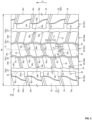
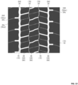
- FIG. 2 is a development view of the tread surface 20.
- the right-left direction is the axial direction of the tire 2
- the up-down direction is the circumferential direction of the tire 2.
- the direction perpendicular to the surface of the drawing sheet of FIG. 2 is the radial direction of the tire 2.
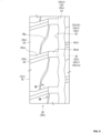
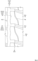
- FIGS. 3 to 5 are each an enlarged development view showing a part of FIG. 2 .
- a direction indicated by an arrow R is the rotation direction of the tire 2.
- the tire 2 running on a road surface comes into contact with the road surface from the upper side toward the lower side of the drawing sheet of FIG. 2 .
- the upper side of the drawing sheet of FIG. 2 is the leading edge side of the tire 2
- the lower side of the drawing sheet of FIG. 2 is the trailing edge side of the tire 2.
- an end TE of the tread surface 20 located on the left side of the equator plane CL being defined as a first end TE1
- an end TE of the tread surface 20 located on the right side of the equator plane CL being defined as a second end TE2.
- the tread pattern of the tire 2 designates the rotation direction of the tire 2.
- a length indicated by reference character TW is the width of the tread surface 20.
- the width TW of the tread surface 20 is the distance in the axial direction from the first end TE1 to the second end TE2.
- the width TW of the tread surface 20 is represented as a length measured along the tread surface 20.
- FIGS. 2 to 5 show the tread pattern of the tire 2.
- a circumferential groove 24 is formed so as to continuously extend in the circumferential direction.
- a plurality of circumferential grooves 24 are formed, thereby forming a plurality of land portions 26 aligned in the axial direction.
- the tread 4 has a plurality of circumferential grooves 24.
- the plurality of circumferential grooves 24 divide the tread 4 into a plurality of land portions 26.
- a length indicated by a double-headed arrow DG is the groove depth of the circumferential groove 24 (specifically, a shoulder circumferential groove described later).
- the groove depth of the circumferential groove 24 is, for example, not less than 10 mm and not greater than 21 mm. From the viewpoint that the tire 2 can exhibit good wet performance, the groove depth is preferably not less than 13 mm and not greater than 18 mm.
- the circumferential groove located on each outermost side in the axial direction is also referred to as shoulder circumferential groove.
- the circumferential groove located on the equator plane is also referred to as center circumferential groove.
- the circumferential groove closest to the equator plane is also referred to as center circumferential groove.
- this circumferential groove is also referred to as middle circumferential groove.
- the tread 4 shown in FIG. 2 has four circumferential grooves 24 aligned in the axial direction.
- the circumferential groove 24 located on each outermost side in the axial direction is a shoulder circumferential groove 24s.
- Each circumferential groove 24 close to the equator plane CL is a center circumferential groove 24c.
- a length indicated by a double-headed arrow Wc is the groove width at the groove opening of the center circumferential groove 24c.
- a length indicated by a double-headed arrow Ws is the groove width at the groove opening of the shoulder circumferential groove 24s.
- the ratio (Wc/TW) of the groove width Wc of the center circumferential groove 24c to the width TW of the tread surface 20 is not greater than 2.0%. As shown in FIG. 2 , the groove width Ws of the shoulder circumferential groove 24s is larger than the groove width Wc of the center circumferential groove 24c. The ratio (Ws/TW) of the groove width Ws of the shoulder circumferential groove 24s to the width TW of the tread surface 20 is greater than 2.0%. Specifically, the ratio (Ws/TW) is preferably not less than 4.0% and not greater than 10%.
- a circumferential groove having, at a groove opening thereof, a groove width of not greater than 2.0% of the width of the tread surface is also referred to as circumferential narrow groove.
- a circumferential groove having, at a groove opening thereof, a groove width of greater than 2.0% of the width of the tread surface is also referred to as circumferential wide groove.
- the center circumferential groove 24c has a groove width Wc of not greater than 2.0% of the width TW of the tread surface 20.
- the center circumferential groove 24c is a circumferential narrow groove 28.
- the shoulder circumferential groove 24s has a groove width Ws of greater than 2.0% of the width TW of the tread surface 20.
- the shoulder circumferential groove 24s is a circumferential wide groove 30.
- the four circumferential grooves 24 formed on the tread 4 include a pair of circumferential narrow grooves 28 and a pair of circumferential wide grooves 30.
- Each circumferential wide groove 30 has a groove width larger than that of each circumferential narrow groove 28.
- a groove having, at a groove opening thereof, a groove width of less than 1.0 mm is also referred to as sipe.
- the circumferential narrow groove has, at a groove opening thereof, a groove width of not less than 1.0 mm.
- Each center circumferential groove 24c is a circumferential narrow groove 28 but is not a sipe.
- the groove width Wc of the center circumferential groove 24c is not less than 1.0 mm.
- the groove width Wc is preferably not less than 1.5 mm.
- the land portion located on each outermost side in the axial direction is also referred to as shoulder land portion.
- the land portion located on the equator plane is also referred to as center land portion.
- the land portion closest to the equator plane is also referred to as center land portion.
- the land portion located between the center land portion and the shoulder land portion is also referred to as middle land portion.
- the tread 4 has five land portions 26 aligned in the axial direction.
- the land portion 26 located on each outermost side in the axial direction is a shoulder land portion 26s.
- the land portion 26 located on the equator plane CL is a center land portion 26c.
- the land portion 26 located between the center land portion 26c and the shoulder land portion 26s is a middle land portion 26m.
- each land portion 26 is determined as appropriate according to the specifications of the tire 2.
- the center land portion 26c is located between the two center circumferential grooves 24c.
- Each middle land portion 26m is located between the center circumferential groove 24c and the shoulder circumferential groove 24s.
- the center land portion 26c and the middle land portions 26m are each the land portion 26 between the adjacent circumferential grooves 24.
- a land portion between adjacent circumferential grooves is also referred to as main land portion.
- the center land portion 26c and the middle land portions 26m are main land portions 32.
- the five land portions 26 formed in the tread 4 include three main land portions 32 each located between the adjacent circumferential grooves 24.
- the plurality of land portions 26 are formed so as to be aligned in the axial direction, and the plurality of land portions 26 include a plurality of main land portions 32 each located between the adjacent circumferential grooves 24.
- the main land portion located on each outermost side in the axial direction is also referred to as outer main land portion.
- the main land portion 32 located on each outermost side in the axial direction is the middle land portion 26m.
- the middle land portion 26m is an outer main land portion 32s.
- Each shoulder circumferential groove 24s is located axially outward of the middle land portion 26m. As described above, the shoulder circumferential groove 24s is a circumferential wide groove 30. The circumferential groove 24 located axially outward of the outer main land portion 32s is a circumferential wide groove 30 having a groove width larger than that of the circumferential narrow groove 28.
- Each shoulder land portion 26s is located axially outward of the shoulder circumferential groove 24s, and includes the end TE of the tread surface 20.
- the shoulder land portion 26s is located further outward of the shoulder circumferential groove 24s which is located on the outermost side in the axial direction.
- the shoulder land portion 26s is not a main land portion 32.
- a land portion 26 may be further provided between the shoulder land portion 26s and the middle land portion 26m.
- this land portion 26 is a main land portion 32.
- a plurality of land portions 26 may be further provided between each shoulder land portion 26s and each middle land portion 26m.
- a plurality of lateral grooves 34 are formed on all the land portions 26 formed in the tread 4 so as to traverse the land portions 26. Accordingly, a plurality of blocks 36 are formed in each land portion 26 so as to be aligned in the circumferential direction.
- the tread pattern of the tire 2 is a block pattern.
- Each lateral groove 34 formed on the center land portion 26c is also referred to as center lateral groove 34c.
- the center lateral groove 34c connects the center circumferential groove 24c on the first end TE1 side of the tread surface 20 (hereinafter, referred to as first center circumferential groove 24c1) and the center circumferential groove 24c on the second end TE2 side of the tread surface 20 (hereinafter, referred to as second center circumferential groove 24c2).
- Each block 36 formed in the center land portion 26c is also referred to as center block 36c.
- a plurality of center lateral grooves 34c divide the center land portion 26c into a plurality of center blocks 36c.
- Each lateral groove 34 formed on each middle land portion 26m is also referred to as middle lateral groove 34m.
- the middle lateral groove 34m connects the shoulder circumferential groove 24s and the center circumferential groove 24c.
- Each block 36 formed in each middle land portion 26m is also referred to as middle block 36m.
- a plurality of middle lateral grooves 34m divide the middle land portion 26m into a plurality of middle blocks 36m.
- Each lateral groove 34 formed on each shoulder land portion 26s is also referred to as shoulder lateral groove 34s.
- the shoulder lateral groove 34s connects the end TE of the tread surface 20 and the shoulder circumferential groove 24s.
- Each block 36 formed in each shoulder land portion 26s is also referred to as shoulder block 36s.
- a plurality of shoulder lateral grooves 34s divide the shoulder land portion 26s into a plurality of shoulder blocks 36s.
- each lateral groove 34 traversing the main land portion 32 is also referred to as main lateral groove 38.
- center land portion 26c and the middle land portions 26m are main land portions 32.
- the center lateral grooves 34c formed on the center land portion 26c and the middle lateral grooves 34m formed on the middle land portions 26m are main lateral grooves 38.
- a plurality of main land portions 32 are formed in the tread 4, and each main land portion 32 has a plurality of main lateral grooves 38 connecting the adjacent circumferential grooves 24.
- a length indicated by a double-headed arrow Wy is the groove width at the groove opening of the main lateral groove 38.
- the groove width Wy of the main lateral groove 38 is not less than 0.55 times and not greater than 0.75 times the groove width Ws of the shoulder circumferential groove 24s. Even when the tire 2 comes into contact with a road surface, a pair of wall surfaces of the main lateral groove 38 do not come into contact with each other.
- each block 36 formed by forming the plurality of main lateral grooves 38 on each main land portion 32 is also referred to as main block 40.
- the center blocks 36c formed by forming the center lateral grooves 34c on the center land portion 26c, and the middle blocks 36m formed by forming the middle lateral grooves 34m on each middle land portion 26m, are main blocks 40.
- the plurality of main lateral grooves 38 formed on each main land portion 32 divide the main land portion 32 into a plurality of main blocks 40 aligned in the circumferential direction.
- each shoulder land portion 26s is not a main land portion 32.
- the shoulder lateral grooves 34s formed on each shoulder land portion 26s are not main lateral grooves 38.
- the shoulder blocks 36s formed by forming the shoulder lateral grooves 34s on each shoulder land portion 26s are not main blocks 40.
- Each circumferential groove 24 includes first proximal portions 42 closer to the first end TE1 of the tread surface 20, and second proximal portions 44 closer to the second end TE2 of the tread surface 20.
- the first proximal portions 42 and the second proximal portions 44 are arranged alternately in the circumferential direction.
- the first proximal portions 42 and the second proximal portions 44 are connected by connection elements CE.
- the circumferential groove 24 does not extend in a straight manner, but extends in a zigzag manner.
- First proximal portions 42c and second proximal portions 44c of each center circumferential groove 24c extend in the circumferential direction.
- the first proximal portions 42c and the second proximal portions 44c have a constant length in the circumferential direction.
- first proximal portions 42s and second proximal portions 44s of each shoulder circumferential groove 24s are formed as bending points.
- connection elements CE connection elements
- the first proximal portions 42c and the second proximal portions 44c of each center circumferential groove 24c may be formed as bending points.
- the first proximal portions 42s and the second proximal portions 44s of each shoulder circumferential groove 24s may be formed so as to have a constant length.
- each first proximal portion 42c1 of the first center circumferential groove 24c1 is equal to the length in the circumferential direction of each second proximal portion 44c2 of the second center circumferential groove 24c2.
- Each first proximal portion 42c1 is located on the trailing edge side with respect to the second proximal portion 44c2 close to the first proximal portion 42c1. In the axial direction, the first proximal portion 42c1 and the second proximal portion 44c2 close to the first proximal portion 42c1 partially overlap each other.
- each second proximal portion 44c 1 of the first center circumferential groove 24c1 is equal to the length in the circumferential direction of each first proximal portion 42c2 of the second center circumferential groove 24c2.
- Each second proximal portion 44c1 is located on the trailing edge side with respect to the first proximal portion 42c2 close to the second proximal portion 44c1. In the axial direction, the second proximal portion 44c1 and the first proximal portion 42c2 close to the second proximal portion 44c1 partially overlap each other.
- each first proximal portion 42c1 of the first center circumferential groove 24c 1 and each second proximal portion 44c2 of the second center circumferential groove 24c2, which have the same length in the circumferential direction, are also referred to as long elements of the center circumferential grooves 24c.
- Each second proximal portion 44c1 of the first center circumferential groove 24c1 and each first proximal portion 42c2 of the second center circumferential groove 24c2, which have the same length in the circumferential direction, are also referred to as short elements of the center circumferential grooves 24c.
- Each long element is longer than each short element.
- the length of the long element (length indicated by a double-headed arrow LL in FIG. 2 ) is preferably not less than 1.1 times and not greater than 1.5 times the length of the short element (length indicated by a double-headed arrow LS in FIG. 2 ).
- Second proximal portions 44s1 of the shoulder circumferential groove 24s on the first end TE1 side of the tread surface 20 include second proximal portions 44s1a each overlapping the first proximal portion 42c1 of the first center circumferential groove 24c1 in the axial direction, and second proximal portions 44s1b each overlapping the second proximal portion 44c1 of the first center circumferential groove 24c1 in the axial direction.
- the second proximal portions 44sla and the second proximal portions 44s1b of the first shoulder circumferential groove 24s 1 are arranged alternately in the circumferential direction with first proximal portions 42s1 interposed therebetween.
- the first proximal portions 42s 1 of the first shoulder circumferential groove 24s 1 include first proximal portions 42s1a each overlapping the shoulder lateral groove 34s in the axial direction, and first proximal portions 42s1b each overlapping the shoulder block 36s in the axial direction.
- the first proximal portions 42sla and the first proximal portions 42s1b of the first shoulder circumferential groove 24s1 are arranged alternately in the circumferential direction with the second proximal portions 44s1 interposed therebetween.
- First proximal portions 42s2 of the shoulder circumferential groove 24s on the second end TE2 side of the tread surface 20 include first proximal portions 42s2a each overlapping the first proximal portion 42c2 of the second center circumferential groove 24c2 in the axial direction, and first proximal portions 42s2b each overlapping the second proximal portion 44c2 of the second center circumferential groove 24c2 in the axial direction.
- the first proximal portions 42s2a and the first proximal portions 42s2b are arranged alternately in the circumferential direction with second proximal portions 44s2 interposed therebetween.
- the second proximal portions 44s2 of the second shoulder circumferential groove 24s2 include second proximal portions 44s2a each overlapping the shoulder lateral groove 34s in the axial direction, and second proximal portions 44s2b each overlapping the shoulder block 36s in the axial direction.
- the second proximal portions 44s2a and the second proximal portions 44s2b are arranged alternately in the circumferential direction with the first proximal portions 42s2 interposed therebetween.
- each shoulder circumferential groove 24s oscillates twice.
- the shoulder circumferential groove 24s can contribute to improving running performance on a wet road surface (wet performance).
- the distance in the axial direction between the first center circumferential groove 24c1 and the second center circumferential groove 24c2 varies in the circumferential direction. This distance in the axial direction is shorter between the second proximal portions 44c 1 of the first center circumferential groove 24c1 and the first proximal portions 42c2 of the second center circumferential groove 24c2, and is longer between the first proximal portions 42c1 of the first center circumferential groove 24c1 and the second proximal portions 44c2 of the second center circumferential groove 24c2.
- the distance in the axial direction between the first shoulder circumferential groove 24s1 and the first center circumferential groove 24c1 also varies in the circumferential direction. This distance in the axial direction is shorter between the second proximal portions 44s1a of the first shoulder circumferential groove 24s1 and the first proximal portions 42c1 of the first center circumferential groove 24c1, and is longer between the first proximal portions 42s1a of the first shoulder circumferential groove 24s1 and the second proximal portions 44c1 of the first center circumferential groove 24c1.
- the distance in the axial direction between the second center circumferential groove 24c2 and the second shoulder circumferential groove 24s2 also varies in the circumferential direction. This distance in the axial direction is shorter between the second proximal portions 44c2 of the second center circumferential groove 24c2 and the first proximal portions 42s2b of the second shoulder circumferential groove 24s2, and is longer between the first proximal portions 42c2 of the second center circumferential groove 24c2 and the second proximal portions 44s2b of the second shoulder circumferential groove 24s2.
- the distance in the axial direction between the adjacent circumferential grooves 24 varies in the circumferential direction.
- Each center lateral groove 34c formed on the center land portion 26c connects the second proximal portion 44c1 of the first center circumferential groove 24c1 and the first proximal portion 42c2 of the second center circumferential groove 24c2 between which the above-described distance in the axial direction is shorter.
- the center lateral groove 34c is located at a portion where the adjacent circumferential grooves 24 are close to each other.
- Each middle lateral groove 34m formed on the middle land portion 26m on the first end TE1 side of the tread surface 20 connects the second proximal portion 44s1a of the first shoulder circumferential groove 24s1 and the first proximal portion 42c1 of the first center circumferential groove 24c1 between which the above-described distance in the axial direction is shorter.
- Each middle lateral groove 34m on the second end TE2 side also connects the second proximal portion 44c2 of the second center circumferential groove 24c2 and the first proximal portion 42s2b of the second shoulder circumferential groove 24s2 between which the above-described distance in the axial direction is shorter.
- the middle lateral groove 34m is also located at a portion where the adjacent circumferential grooves 24 are close to each other.
- each center lateral groove 34c and each middle lateral groove 34m are main lateral grooves 38.
- Each main lateral groove 38 formed on each main land portion 32 is located at a portion where the adjacent circumferential grooves 24 are close to each other.
- each end TE of the tread surface 20 and each shoulder circumferential groove 24s also varies in the circumferential direction.
- this distance in the axial direction is shorter at the first proximal portions 42s1 of the first shoulder circumferential groove 24s1, and is longer at the second proximal portions 44s1 of the first shoulder circumferential groove 24s1.
- Each shoulder lateral groove 34s on the first end TE1 side connects the first end TE1 and the first proximal portion 42s1 (specifically, the above-described first proximal portion 42s1a) between which the above-described distance in the axial direction is shorter.
- this distance in the axial direction is shorter at the second proximal portions 44s2 of the second shoulder circumferential groove 24s2, and is longer at the first proximal portions 42s2 of the second shoulder circumferential groove 24s2.
- Each shoulder lateral groove 34s on the second end TE2 side connects the second proximal portion 44s2 (specifically, the above-described second proximal portion 44s2a) and the second end TE2 between which the above-described distance in the axial direction is shorter.
- each shoulder lateral groove 34s is located at a portion where the shoulder circumferential groove 24s is close to the end TE of the tread surface 20.
- FIG. 6 is a cross-sectional view of the center lateral groove 34c taken along a line VI-VI in FIG. 3 .
- FIG. 6 shows a cross-section of the center lateral groove 34c along a plane perpendicular to the length direction of the center lateral groove 34c.
- each center lateral groove 34c is a main lateral groove 38.
- FIG. 6 shows a cross-section of the main lateral groove 38.
- each middle lateral groove 34m is also a main lateral groove 38.
- a cross-sectional shape of the middle lateral groove 34m is the same as that of the center lateral groove 34c. The description of the cross-sectional shape of the middle lateral groove 34m is omitted.
- Each main lateral groove 38 includes a lateral groove body 54 and a bottom sipe portion 56.
- the lateral groove body 54 includes a groove opening 38a of the main lateral groove 38.
- the groove width of the lateral groove body 54 is not less than 1.0 mm.
- the lateral groove body 54 is not a sipe.
- the bottom sipe portion 56 includes a bottom 38b of the main lateral groove 38.
- the groove width of the bottom sipe portion 56 is smaller than the groove width of the lateral groove body 54. Specifically, the groove width of the bottom sipe portion 56 is less than 1.0 mm.
- the bottom sipe portion 56 is a sipe.
- the lateral groove body 54 includes a tapered portion 58 and a body portion 60.
- the tapered portion 58 includes the above-described groove opening 38a.
- the tapered portion 58 is tapered inward from the groove opening 38a.
- the body portion 60 is located radially inward of the tapered portion 58.
- the body portion 60 is connected to the tapered portion 58.
- the boundary between the body portion 60 and the tapered portion 58 is a groove opening 60a of the body portion 60.
- the body portion 60 is tapered inward from the groove opening 60a.
- the body portion 60 includes a bottom 54b of the lateral groove body 54.
- the groove width of the body portion 60 is larger than the groove width of the bottom sipe portion 56.
- the lateral groove body 54 does not have to be provided with the tapered portion 58.
- a cross-sectional shape of the lateral groove body 54 is shaped such that the wall surfaces of the body portion 60 shown in FIG. 6 are caused to spread outward and the position of the point of intersection of an extension line of each wall surface and an extension line of the tread surface 20 is at the groove opening 60a of the body portion 60, that is, the groove opening 38a of the main lateral groove 38.
- the lateral groove body 54 of the main lateral groove 38 is preferably provided with the tapered portion 58 as shown in FIG. 6 .
- the bottom sipe portion 56 is located radially inward of the lateral groove body 54.
- the bottom sipe portion 56 is formed at the bottom 54b of the lateral groove body 54.
- the bottom sipe portion 56 extends further inward from the bottom 54b of the lateral groove body 54.
- the bottom sipe portion 56 is shaped by a blade composed of a flat plate.
- the wall surfaces of the bottom sipe portion 56 are formed as flat surfaces.
- a length indicated by a double-headed arrow MY is the groove depth of the main lateral groove 38.
- a length indicated by a double-headed arrow MH is the groove depth of the lateral groove body 54.
- a length indicated by a double-headed arrow MT is the groove depth of the tapered portion 58.
- the groove depth MY of the main lateral groove 38 is slightly shallower than the groove depth DG of the circumferential groove 24. Specifically, the groove depth MY is suitably set in a range of not less than 0.85 times and not greater than 0.95 times the groove depth DG of the circumferential groove 24.
- the ratio (MT/MY) of the groove depth MT of the tapered portion 58 to the groove depth MY of the main lateral groove 38 is preferably not less than 0.12 and not greater than 0.14.
- FIG. 7 is a cross-sectional view of the shoulder lateral groove 34s taken along a line VII-VII in FIG. 4 .
- FIG. 7 shows a cross-section of the shoulder lateral groove 34s along a plane perpendicular to the length direction of the shoulder lateral groove 34s.
- the shoulder lateral groove 34s includes a deep bottom portion 34sd on the shoulder circumferential groove 24s side, and a shallow bottom portion 34ss on the end TE side of the tread surface 20.
- FIG. 7 shows a cross-sectional shape of the shallow bottom portion 34ss.
- the deep bottom portion 34sd has the same cross-sectional shape as the cross-sectional shape of the shoulder circumferential groove 24s. The description of the cross-sectional shape of the deep bottom portion 34sd is omitted.
- a narrow groove 36g is formed so as to connect the deep bottom portion 34sd on the leading edge side and the shallow bottom portion 34ss on the trailing edge side.
- the shallow bottom portion 34ss of the shoulder lateral groove 34s includes a lateral groove body 62 and a bottom sipe portion 64.
- the lateral groove body 62 includes a groove opening 34sa of the shoulder lateral groove 34s.
- the groove width of the lateral groove body 62 is not less than 1.0 mm.
- the lateral groove body 62 is not a sipe.
- the bottom sipe portion 64 includes a bottom 34sb of the shoulder lateral groove 34s.
- the groove width of the bottom sipe portion 64 is smaller than the groove width of the lateral groove body 62. Specifically, the groove width of the bottom sipe portion 64 is less than 1.0 mm.
- the bottom sipe portion 64 is a sipe.
- the lateral groove body 62 includes a tapered portion 66 and a body portion 68.
- the tapered portion 66 includes the above-described groove opening 34sa.
- the tapered portion 66 is tapered inward from the groove opening 34sa.
- the body portion 68 is located radially inward of the tapered portion 66.
- the body portion 68 is connected to the tapered portion 66.
- the boundary between the body portion 68 and the tapered portion 66 is a groove opening 68a of the body portion 68.
- the body portion 68 is tapered inward from the groove opening 68a.
- the body portion 68 includes a bottom 62b of the lateral groove body 62.
- the groove width of the body portion 68 is larger than the groove width of the bottom sipe portion 64.
- the lateral groove body 62 does not have to be provided with the tapered portion 66.
- a cross-sectional shape of the lateral groove body 62 is shaped such that the wall surfaces of the body portion 68 shown in FIG. 7 are caused to spread outward and the position of the point of intersection of an extension line of each wall surface and an extension line of the tread surface 20 is at the groove opening 68a of the body portion 68, that is, the groove opening 34sa of the shoulder lateral groove 34s.
- the lateral groove body 62 of the shoulder lateral groove 34s is preferably provided with the tapered portion 66 as shown in FIG. 7 .
- the bottom sipe portion 64 is located radially inward of the lateral groove body 62.
- the bottom sipe portion 64 is formed at the bottom 62b of the lateral groove body 62.
- the bottom sipe portion 64 extends further inward from the bottom 62b of the lateral groove body 62.
- the bottom sipe portion 64 is shaped by a blade composed of a flat plate.
- the wall surfaces of the bottom sipe portion 64 are formed as flat surfaces.
- a length indicated by a double-headed arrow SY is the groove depth of the shoulder lateral groove 34s.
- a length indicated by a double-headed arrow SH is the groove depth of the lateral groove body 62.
- a length indicated by a double-headed arrow ST is the groove depth of the tapered portion 66.
- the groove depth SY of the shoulder lateral groove 34s is substantially equal to the groove depth MY of the main lateral groove 38. Specifically, the ratio (SY/MY) of the groove depth SY of the shoulder lateral groove 34s to the groove depth MY of the main lateral groove 38 is not less than 0.95 and not greater than 1.05.
- the ratio (ST/SY) of the groove depth ST of the tapered portion 66 to the groove depth SY of the shoulder lateral groove 34s is also substantially equal to the ratio (MT/MY).
- the ratio (ST/SY) is preferably not less than 0.12 and not greater than 0.14.
- the lateral groove body 62 of the shoulder lateral groove 34s is preferably shallower than the lateral groove body 54 of the main lateral groove 38.
- the ratio (SH/MH) of the groove depth SH of the lateral groove body 62 of the shoulder lateral groove 34s to the groove depth MH of the lateral groove body 54 of the main lateral groove 38 is preferably not less than 0.50 and not greater than 0.70.
- the center blocks 36c formed by forming the center lateral grooves 34c on the center land portion 26c and the middle blocks 36m formed by forming the middle lateral grooves 34m on each middle land portion 26m are main blocks 40.
- transverse sipes 70 are provided so as to traverse the main blocks 40.
- the transverse sipes 70 of the tire 2 are provided on the center blocks 36c of the center land portion 26c and the middle blocks 36m of the middle land portions 26m.
- a transverse sipe 70 may be provided only on each center block 36c.
- a transverse sipe 70 may be provided only on each middle block 36m. That is, in the tire 2, in at least one main land portion 32 out of the plurality of main land portions 32, the plurality of main blocks 40 each have a transverse sipe 70.
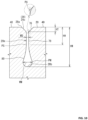
- FIG. 8 is a cross-sectional view taken along a line VIII-VIII in FIG. 3 .
- FIG. 8 shows a cross-section of the transverse sipe 70.
- FIG. 8 shows a cross-section of the transverse sipe 70 along a plane perpendicular to the length direction of the transverse sipe 70.
- FIG. 8 shows a cross-section of the transverse sipe 70 provided on the center block 36c. As described above, the transverse sipe 70 is also provided on each middle block 36m. A cross-sectional shape of the transverse sipe 70 on each middle block 36m is the same as that of the transverse sipe 70 on each center block 36c. The description of the cross-sectional shape of the transverse sipe 70 on each middle block 36m is omitted.
- the transverse sipe 70 includes a sipe body 72 and a tubular portion 74.
- the sipe body 72 includes a groove opening 70a of the transverse sipe 70.
- the tubular portion 74 includes a bottom 70b of the transverse sipe 70.
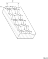
- the sipe body 72 extends in a zigzag manner in the length direction of the transverse sipe 70. Although not shown, the sipe body 72 may extend in a straight manner in the length direction.
- the sipe body 72 extends in a zigzag manner in the depth direction of the transverse sipe 70.
- the sipe body 72 may extend in a straight manner as shown in FIG. 9 .
- the tubular portion 74 is located radially inward of the sipe body 72.
- the tubular portion 74 extends in the length direction of the transverse sipe 70.
- a solid line LM is a boundary line between the sipe body 72 and the tubular portion 74.
- a length indicated by a double-headed arrow WM is the groove width of the transverse sipe 70 measured along the boundary line LM.
- the boundary line LM is set at a position at which the groove width WM is 1.0 mm.
- the transverse sipe 70 has a groove width Wp of less than 1.0 mm at the groove opening 70a thereof.
- the groove width of a portion outside the boundary line LM, that is, the sipe body 72, is less than 1.0 mm.
- the sipe body 72 is a sipe.
- the groove width of a portion inside the boundary line LM, that is, the tubular portion 74, is not less than 1.0 mm.
- the groove width of the tubular portion 74 is larger than the groove width of the sipe body 72.
- the tubular portion 74 extends inward from the position of the boundary line LM.
- a length indicated by a double-headed arrow WT is the maximum groove width of the tubular portion 74.
- a position indicated by reference character PT is the position at which the tubular portion 74 has the maximum groove width WT.
- the tubular portion 74 is tapered outward from a portion where the tubular portion 74 has the maximum groove width WT.
- the tubular portion 74 is tapered inward from the portion where the tubular portion 74 has the maximum groove width WT.
- a cross-sectional shape of the tubular portion 74 may be circular or elliptical.
- This cross-sectional shape may be a shape in which the portion where the tubular portion 74 has the maximum groove width WT is represented by a straight line and the sipe body 72 side and the bottom 70b side of the straight line portion are represented by arcs (hereinafter, this shape is also referred to as track shape).
- a length indicated by a double-headed arrow DA is the groove depth of the transverse sipe 70.
- a length indicated by a double-headed arrow DC is the groove depth of the sipe body 72.
- the groove depth DA of the transverse sipe 70 is substantially equal to the groove depth DG of the circumferential groove 24. Specifically, the groove depth DA of the transverse sipe 70 is not less than 0.95 times and not greater than 1.05 times the groove depth DG of the circumferential groove 24.
- FIG. 10 is a cross-sectional view of the center circumferential groove 24c taken along a line X-X in FIG. 3 .
- FIG. 10 shows a cross-section of the center circumferential groove 24c along a plane perpendicular to the length direction of the center circumferential groove 24c.
- each center circumferential groove 24c is a circumferential narrow groove 28.
- FIG. 10 shows a cross-section of the circumferential narrow groove 28.
- the circumferential narrow groove 28 includes a tapered portion 76, a body portion 78, and an enlarged width portion 80.
- the tapered portion 76 includes a groove opening 28a of the circumferential narrow groove 28.
- the tapered portion 76 is tapered inward from the groove opening 28a.
- a contour of each wall surface of the tapered portion 76 shown in FIG. 10 is represented by a straight line. This contour may be represented by a curve.
- the body portion 78 is located radially inward of the tapered portion 76.
- the body portion 78 is connected to the tapered portion 76.
- the body portion 78 extends in a straight manner.
- a contour of each wall surface of the body portion 78 is represented by a straight line.
- a length indicated by a double-headed arrow WD is the groove width of the body portion 78.
- the enlarged width portion 80 is located radially inward of the body portion 78.
- the enlarged width portion 80 is connected to the body portion 78.
- the enlarged width portion 80 has a groove width larger than the groove width WD of the body portion 78.
- the enlarged width portion 80 includes a bottom 28b of the circumferential narrow groove 28.
- a position indicated by reference character PU is the boundary between the tapered portion 76 and the body portion 78.
- the boundary PU is represented as the point of intersection of the wall surface contour line of the tapered portion 76 and the wall surface contour line of the body portion 78.
- the boundary PU is represented as the point of intersection of an extension line of the wall surface contour line of the tapered portion 76 and an extension line of the wall surface contour line of the body portion 78.
- a position indicated by reference character PS is the boundary between the body portion 78 and the enlarged width portion 80.
- each wall surface contour line of the body portion 78 is a straight line.
- the position at which a wall surface contour line of the enlarged width portion 80 converges with the wall surface contour line of the body portion 78 is the boundary PS between the body portion 78 and the enlarged width portion 80.
- the position at which the groove width from the body portion 78 to the enlarged width portion 80 is 1.1 times the groove width WD of the body portion 78 is represented as the boundary PS between the body portion 78 and the enlarged width portion 80.
- a length indicated by a double-headed arrow WM is the maximum groove width of the enlarged width portion 80.
- a position indicated by reference character PM is the position at which the enlarged width portion 80 has the maximum groove width WM.
- the enlarged width portion 80 is tapered outward from a portion where the enlarged width portion 80 has the maximum groove width WM. In the portion from the maximum groove width position PM to the boundary PS, the enlarged width portion 80 is curved so as to be recessed inward from the outer side thereof.
- the enlarged width portion 80 is tapered inward from the portion where the enlarged width portion 80 has the maximum groove width WM. In the portion from the maximum groove width position PM to the bottom 28b, the enlarged width portion 80 has a rounded contour. In this portion, the enlarged width portion 80 is curved so as to bulge outward from the inner side thereof.
- the boundary between the portion curved so as to be recessed inward from the outer side thereof and the portion curved so as to bulge outward from the inner side thereof is located radially outward of the maximum groove width position PM.
- the circumferential narrow groove 28 does not have to be provided with the tapered portion 76.
- a cross-sectional shape of the circumferential narrow groove 28 is shaped such that the wall surfaces of the body portion 78 shown in FIG. 10 are caused to spread outward and the position of the point of intersection of an extension line of each wall surface and an extension line of the tread surface 20 is at the groove opening of the body portion 78, that is, the groove opening 28a of the circumferential narrow groove 28.
- the circumferential narrow groove 28 is preferably provided with the tapered portion 76 as shown in FIG. 10 .
- a length indicated by a double-headed arrow HM is the groove depth of the circumferential narrow groove 28.
- the groove depth HM is equal to the above-described groove depth DG of the circumferential groove 24.
- a length indicated by a double-headed arrow HH is the groove depth of a portion composed of the tapered portion 76 and the body portion 78.
- a length indicated by a double-headed arrow HT is the groove depth of the tapered portion 76.
- the portion composed of the tapered portion 76 and the body portion 78 is also referred to as narrow groove body 28m.
- the ratio (HT/HM) of the groove depth HT of the tapered portion 76 to the groove depth HM of the circumferential narrow groove 28 is preferably not less than 0.12 and not greater than 0.14.
- FIG. 11 is a cross-sectional view of the shoulder circumferential groove 24s taken along a line XI-XI in FIG. 2 .
- FIG. 11 shows a cross-section of the shoulder circumferential groove 24s along a plane perpendicular to the length direction of the shoulder circumferential groove 24s.
- each shoulder circumferential groove 24s is a circumferential wide groove 30.
- FIG. 11 shows a cross-section of the circumferential wide groove 30.
- the circumferential wide groove 30 includes a tapered portion 82 and a body portion 84.
- the tapered portion 82 includes a groove opening 30a of the circumferential wide groove 30.
- the tapered portion 82 is tapered inward from the groove opening 30a.
- the body portion 84 is located radially inward of the tapered portion 82.
- the body portion 84 is connected to the tapered portion 82.
- the boundary between the body portion 84 and the tapered portion 82 is a groove opening 84a of the body portion 84.
- the body portion 84 is tapered inward from the groove opening 84a.
- the body portion 84 includes a bottom 30b of the circumferential wide groove 30.
- a pair of wall surfaces of the circumferential wide groove 30 do not come into contact with each other even when the tire 2 comes into contact with a road surface and the tread 4 becomes deformed.
- the circumferential wide groove 30 does not have to be provided with the tapered portion 82.
- a cross-sectional shape of the circumferential wide groove 30 is shaped such that the wall surfaces of the body portion 84 shown in FIG. 11 are caused to spread outward and the position of the point of intersection of an extension line of each wall surface and an extension line of the tread surface 20 is at the groove opening 84a of the body portion 84, that is, the groove opening 30a of the circumferential wide groove 30.
- the circumferential wide groove 30 is preferably provided with the tapered portion 82 as shown in FIG. 11 .
- a length indicated by a double-headed arrow FM is the groove depth of the circumferential wide groove 30.
- the groove depth FM is equal to the groove depth DG of the above-described circumferential groove 24.
- a length indicated by a double-headed arrow FT is the groove depth of the tapered portion 82.
- the ratio (FT/FM) of the groove depth FT of the tapered portion 82 to the groove depth FM of the circumferential wide groove 30 is preferably not less than 0.12 and not greater than 0.14.
- the plurality of land portions 26 are formed in the tread 4 of the tire 2 so as to be aligned in the axial direction.
- the plurality of land portions 26 include the plurality of main land portions 32.
- the circumferential grooves 24 are located on both sides of each main land portion 32. As shown in FIG. 2 , the plurality of main land portions 32 located between the adjacent circumferential grooves 24 are formed in a crown portion of the tread portion.
- Each main land portion 32 has the plurality of main lateral grooves 38 connecting the adjacent circumferential grooves 24.
- the lateral groove body 54 of each main lateral groove 38 is shallower than the circumferential groove 24.
- the shallower lateral groove body 54 increases the stiffness of the crown portion.
- each circumferential groove 24 located between the adjacent main land portions 32 is a circumferential narrow groove 28.
- the distance between the wall surfaces at the body portion 78 of the circumferential narrow groove 28 is short.
- the tread 4 becomes deformed. If the circumferential narrow groove 28 is formed such that the left and right wall surfaces at the body portion 78 can contact with each other due to this deformation, the adjacent main land portions 32 support each other. In this case, the apparent stiffness of the crown portion is increased, and deformation of the crown portion is further suppressed.
- the plurality of main lateral grooves 38 divide the main land portion 32 into the plurality of main blocks 40 aligned in the circumferential direction.
- the plurality of main blocks 40 each have the transverse sipe 70.
- the sipe body 72 of the transverse sipe 70 reduces specific strain generated in the main block 40.
- the tire 2 can reduce the ground-contact pressure of the crown portion. Occurrence of center wear is suppressed.
- the tire 2 can have improved uneven wear resistance.
- the lateral groove body 54 Since the lateral groove body 54 is shallower, the lateral groove body 54 disappears relatively early due to wear of the tread 4. Therefore, there is a concern about deterioration in appearance quality and deterioration in traction performance.
- each main lateral groove 38 includes the bottom sipe portion 56 on the radially inner side of the shallower lateral groove body 54.
- Each transverse sipe 70 includes the tubular portion 74 on the radially inner side of the sipe body 72.
- Each circumferential narrow groove 28 includes the enlarged width portion 80 on the radially inner side of the body portion 78.
- FIGS. 12 to 14 show changes in the tread pattern due to wear of the tread 4.
- FIG. 12 is a transfer diagram of the tread pattern when the tire 2 is new.
- FIG. 13 is a transfer diagram of the tread pattern in a state where a medium degree of wear has occurred (hereafter, referred to as intermediate state of wear).
- FIG. 14 is a transfer diagram of the tread pattern upon reaching a state where replacement of the tire 2 is required when further wear has occurred (hereinafter, referred to as end state of wear).
- the area of the portion corresponding to the grooves 22 is decreased as a whole.
- the tapered portion 58 of the lateral groove body 54 disappears, exposing the body portion 60.
- the exposed state of the sipe body 72 is maintained.
- the tapered portions 76 disappear, exposing the body portions 78.
- each shoulder block 36s and the lateral groove body 62 of each shallow bottom portion 34ss which forms a part of the shoulder lateral groove 34s disappear, exposing the bottom sipe portion 64 of the shallow bottom portion 34ss.
- the area of the portion corresponding to the grooves 22 is further decreased as a whole.
- the body portion 60 of the lateral groove body 54 that is, the entirety of the lateral groove body 54, disappears, exposing the bottom sipe portion 56.
- the sipe body 72 disappears, exposing the tubular portion 74.
- the body portion 78 disappears, exposing the enlarged width portion 80.
- the groove components extending in the axial direction in addition to the circumferential grooves 24 are kept exposed.
- the tire 2 can maintain good appearance quality and good traction performance.
- the tire 2 can have improved uneven wear resistance and can suppress deterioration in appearance quality and traction performance due to progress of wear.
- the entirety of the tubular portion 74 of each transverse sipe 70 is preferably located radially inward of the bottom 54b of the lateral groove body 54 of each main lateral groove 38.
- the groove depth DC of the sipe body 72 of each transverse sipe 70 is preferably larger than the groove depth MH of the lateral groove body 54 of each main lateral groove 38. Accordingly, after the lateral groove body 54 of the main lateral groove 38 disappears, the tubular portion 74 of the transverse sipe 70 is exposed.
- the wear of the tread 4 can be caused to progress while maintaining the stiffness of the main block 40.
- the tire 2 can suppress occurrence of center wear, and thus can maintain good uneven wear resistance.
- the bottom sipe portion 56 is exposed in the main lateral groove 38, and the tubular portion 74 is exposed in the transverse sipe 70.
- the tire 2 can also suppress deterioration in appearance quality and traction performance due to the disappearance of the lateral groove body 54.
- the ratio (DC/HM) of the groove depth DC of the sipe body 72 of each transverse sipe 70 to the groove depth HM of each circumferential narrow groove 28 is preferably not less than 60% and not greater than 80%.
- each tubular portion 74 can be exposed in the tire 2 at an appropriate timing.
- the tire 2 allows the wear of the tread 4 to progress while maintaining the stiffness of the main block 40.
- the tire 2 can effectively suppress occurrence of center wear, and thus can maintain good uneven wear resistance.
- the ratio (DC/HM) is more preferably not less than 65%.
- the ratio (DC/HM) is set to be not greater than 80%, the tubular portion 74 can effectively contribute to improving appearance quality and exhibiting traction performance. From this viewpoint, the ratio (DC/HM) is more preferably not greater than 75%.
- the ratio (MH/HM) of the groove depth MH of the lateral groove body 54 of each main lateral groove 38 to the groove depth HM of each circumferential narrow groove 28 is preferably not less than 30% and not greater than 60%.
- each lateral groove body 54 can be caused to disappear in the tire 2 at an appropriate timing.
- the tire 2 can maintain good appearance quality and traction performance. From this viewpoint, the ratio (MH/HM) is more preferably not less than 35%.
- the tire 2 can effectively suppress the influence of the lateral groove body 54 on the stiffness of the main block 40.
- the tire 2 allows the wear of the tread 4 to progress while maintaining the stiffness of the main block 40.
- the tire 2 can effectively suppress occurrence of center wear, and thus can maintain good uneven wear resistance.
- the ratio (MH/HM) is more preferably not greater than 55%.
- the ratio (DC/HM) is not less than 60% and not greater than 80%, and the ratio (MH/HM) is not less than 30% and not greater than 60%.
- the entirety of the bottom sipe portion 56 of each main lateral groove 38 is preferably located radially inward of the narrow groove body 28m of each circumferential narrow groove 28.
- the groove depth MH of the lateral groove body 54 of each main lateral groove 38 is preferably larger than the groove depth HH of the narrow groove body 28m of each circumferential narrow groove 28.
- the groove width of the enlarged width portion 80 of the circumferential narrow groove 28 gradually increases radially inward from the boundary PS between the narrow groove body 28m and the enlarged width portion 80.
- the ratio (HH/HM) of the groove depth HH of the narrow groove body 28m of each circumferential narrow groove 28 to the groove depth HM of each circumferential narrow groove 28 is preferably not less than 20% and not greater than 50%.
- the tire 2 can effectively suppress the influence of the enlarged width portion 80 on the stiffness of the main block 40.
- the tire 2 allows the wear of the tread 4 to progress while maintaining the stiffness of the main block 40.
- the tire 2 can effectively suppress occurrence of center wear, and thus can maintain good uneven wear resistance.
- the ratio (HH/HM) is more preferably not less than 25%.
- the ratio (HH/HM) is set to be not greater than 50%, the enlarged width portion 80 can effectively contribute to suppressing a rapid change in the stiffness of the main block 40 during the period from when the lateral groove body 54 disappears to when the tubular portion 74 of the transverse sipe 70 is exposed. From this viewpoint, the ratio (HH/HM) is more preferably not greater than 45%.
- each circumferential narrow groove 28 of the tire 2 has the groove width WD smaller than the groove width Ws at the groove opening of the shoulder circumferential groove 24s.
- the main blocks 40 adjacent to each other across the circumferential narrow groove 28 support each other.
- each main land portion 32 including the main blocks 40 is formed in the crown portion of the tread portion. Since the adjacent main blocks 40 support each other, the apparent stiffness of the crown portion is increased, and deformation of the crown portion is suppressed.
- the tire 2 can effectively suppress occurrence of wear at the crown portion.
- the tire 2 can have improved uneven wear resistance.
- the ratio (WD/Ws) of the groove width WD of the body portion 78 of each circumferential narrow groove 28 to the groove width Ws of each shoulder circumferential groove 24s is preferably not greater than 0.35 and more preferably not greater than 0.20.
- the ratio (WD/Ws) is preferably not less than 0.01 and more preferably not less than 0.05.
- the enlarged width portion 80 has a groove width larger than the groove width WD of the body portion 78.
- the maximum groove width WM of the enlarged width portion 80 is preferably not less than two times and more preferably not less than three times the groove width WD of the body portion 78.
- the circumferential narrow groove 28 is provided on the crown portion. From the viewpoint that the influence on the stiffness of the crown portion is suppressed and the tire 2 can maintain good uneven wear resistance, the maximum groove width WM of the enlarged width portion 80 is preferably not greater than 8 times and more preferably not greater than 7 times the groove width WD of the body portion 78.
- each center lateral groove 34c formed on the center land portion 26c connects the second proximal portion 44c1 of the first center circumferential groove 24c1 and the first proximal portion 42c2 of the second center circumferential groove 24c2.
- Each center lateral groove 34c is a main lateral groove 38, and each center circumferential groove 24c is a circumferential narrow groove 28.
- the main lateral groove 38 extends between the second proximal portion 44c1 of a first circumferential narrow groove 28a and the first proximal portion 42c2 of a second circumferential narrow groove 28b.
- each main block 40 formed between the first circumferential narrow groove 28a and the second circumferential narrow groove 28b is located between the main lateral groove 38 on the leading edge side and the main lateral groove 38 on the trailing edge side in the circumferential direction, and is located between the first proximal portion 42c1 of the first circumferential narrow groove 28a and the second proximal portion 44c2 of the second circumferential narrow groove 28b, which are long elements, in the axial direction.
- each first proximal portion 42c1 of the first circumferential narrow groove 28a and each second proximal portion 44c2 of the second circumferential narrow groove 28b may be larger than the distance in the axial direction between each second proximal portion 44c1 of the first circumferential narrow groove 28a and each first proximal portion 42c2 of the second circumferential narrow groove 28b.
- Each main block 40 formed between the adjacent circumferential narrow grooves 28 is surrounded by two main lateral grooves each located at a portion where the adjacent circumferential narrow grooves 28 are close to each other, and two long elements as elements of the circumferential narrow grooves 28.
- the main block 40 has an octagon-like shape.
- the tire 2 can suppress an increase in ground-contact pressure at the edge of the main block 40. Since occurrence of center wear is suppressed, the tire 2 can have improved uneven wear resistance.
- each main lateral groove 38 located at a portion where the adjacent circumferential groove 24 are close to each other preferably extends between the second proximal portion 44c1 of the first circumferential narrow groove 28a and the first proximal portion 42c2 of the second circumferential narrow groove 28b.
- the adjacent circumferential grooves 24 are more preferably the first center circumferential groove 24c1 and the second center circumferential groove 24c2.
- the above-described main block 40 having an octagon-like shape is formed in the center land portion 26c.
- each main lateral groove 38 is tilted relative to the axial direction.
- the axially inner end of the main lateral groove 38 is located on the leading edge side with respect to the axially outer end thereof.
- the main lateral groove 38 extends from the axially inner end to the axially outer end thereof.
- the main lateral groove 38 can effectively drain water existing between the tire 2 and the road surface, from a ground-contact surface of the tire 2.
- the tire 2 can have improved wet performance.
- each main lateral groove 38 is tilted relative to the axial direction, and the axially inner end of the main lateral groove 38 comes into contact with a road surface earlier than the axially outer end thereof.
- FIG. 15 shows a wall surface of the transverse sipe 70 formed on the main block 40.
- the sipe body 72 of this transverse sipe 70 extends in a zigzag manner in the length direction thereof and extends in a zigzag manner in the depth direction thereof.
- a sipe having such a wall surface is also referred to as Miura-fold (three-dimensional) sipe.
- the wall surfaces of the sipe body 72 come into contact with each other and support each other.
- the sipe body 72 increases the apparent stiffness of the main block 40. Deformation of the main block 40 is suppressed.
- the tire 2 can have further improved uneven wear resistance.
- the sipe body 72 of the transverse sipe 70 preferably extends in a zigzag manner in the length direction thereof and extends in a zigzag manner in the depth direction thereof.
- the groove width of the tubular portion 74 is larger than the groove width of the sipe body 72.
- the maximum groove width WT of the tubular portion 74 is preferably not less than 4 times and more preferably not less than 5 times the groove width of the sipe body 72 at the groove opening, that is, the groove width Wp of the transverse sipe 70. Accordingly, the tubular portion 74 can contribute to maintaining wet performance.
- the maximum groove width WT of the tubular portion 74 is preferably not greater than 13 times and more preferably not greater than 12 times the groove width Wp of the transverse sipe 70. Accordingly, the size of the tubular portion 74 is appropriately maintained. A decrease in the stiffness of the main block 40 is suppressed.
- the tubular portion 74 includes a bottom surface including the bottom 70b of the transverse sipe 70.
- a contour of the bottom surface of the tubular portion 74 is represented by an arc passing through the bottom 70b.
- an arrow Rb represents the radius of this arc.
- the radius Rb of the arc representing the contour of the bottom surface of the tubular portion 74 is preferably not less than 1.5 mm and not greater than 3.5 mm.
- the radius Rb is set to be not less than 1.5 mm, occurrence of cracking at the bottom 70b is effectively suppressed. From this viewpoint, the radius Rb is more preferably not less than 2.0 mm.
- the radius Rb is set to be not greater than 3.5 mm, a decrease in the stiffness of the main block 40 due to the tubular portion 74 provided in the transverse sipe 70 is suppressed.
- the stiffness of the main block 40 is appropriately maintained.
- the tire 2 can have improved uneven wear resistance. From this viewpoint, the radius Rb is more preferably not greater than 3.0 mm.
- a heavy duty tire that can have improved uneven wear resistance and can suppress deterioration in appearance quality and traction performance due to progress of wear, is obtained.
- the above-described technology capable of improving uneven wear resistance and suppressing deterioration in appearance quality and traction performance due to progress of wear can be applied to various tires.
Landscapes
- Engineering & Computer Science (AREA)
- Mechanical Engineering (AREA)
- Tires In General (AREA)
Abstract
Description
- The present invention relates to a heavy duty tire. Specifically, the present invention relates to a heavy duty tire in which a block pattern is employed as a tread pattern.
- In a heavy duty tire in which a block pattern is employed, the ground-contact pressure of a crown portion tends to increase. High ground-contact pressure promotes progress of wear. In this tire, center wear is likely to occur. Various studies have been conducted in order to suppress occurrence of center wear and improve uneven wear resistance (e.g.,
Japanese Laid-Open Patent Publication No. 2012-201253 - An object of the present invention is to provide a heavy duty tire that can have improved uneven wear resistance and can suppress deterioration in appearance quality and traction performance due to progress of wear.
- A tire according to the present invention is a heavy duty tire including a tread having a tread surface configured to come into contact with a road surface. The tread has a plurality of circumferential grooves continuously extending in a circumferential direction. The plurality of circumferential grooves divide the tread into a plurality of land portions aligned in an axial direction. The plurality of land portions include a plurality of main land portions each located between the adjacent circumferential grooves. Each of the main land portions has a plurality of main lateral grooves connecting the adjacent circumferential grooves. The plurality of main lateral grooves divide the main land portion into a plurality of main blocks aligned in the circumferential direction. Each of the main lateral grooves formed on the main land portion is located at a portion where the adjacent circumferential grooves are close to each other. Each of the main lateral grooves includes a lateral groove body and a bottom sipe portion formed at a bottom of the lateral groove body. The lateral groove body is shallower than the circumferential groove, and the bottom sipe portion has a groove width smaller than a groove width of the lateral groove body. The plurality of main blocks in at least one main land portion each have a transverse sipe traversing the main block. The transverse sipe includes a sipe body and a tubular portion located radially inward of the sipe body. The tubular portion has a groove width larger than a groove width of the sipe body. The circumferential groove located between the adjacent main land portions is a circumferential narrow groove. The main land portion located on each outermost side in the axial direction, among the plurality of main land portions, is an outer main land portion. The circumferential groove located axially outward of the outer main land portion is a circumferential wide groove having a groove width larger than a groove width of the circumferential narrow groove. The circumferential narrow groove includes a body portion and an enlarged width portion located radially inward of the body portion. The enlarged width portion has a groove width larger than a groove width of the body portion.
- The present invention can provide a tire that can have improved uneven wear resistance and can suppress deterioration in appearance quality and traction performance due to progress of wear.
-
-
FIG. 1 is a cross-sectional view showing a part of a heavy duty tire according to one embodiment of the present invention; -
FIG. 2 is a development view showing a part of a tread of the tire inFIG. 1 ; -
FIG. 3 is a development view showing a part ofFIG. 2 ; -
FIG. 4 is a development view showing a part ofFIG. 2 ; -
FIG. 5 is a development view showing a part ofFIG. 2 ; -
FIG. 6 is a cross-sectional view taken along a line VI-VI inFIG. 3 ; -
FIG. 7 is a cross-sectional view taken along a line VII-VII inFIG. 4 ; -
FIG. 8 is a cross-sectional view taken along a line VIII-VIII inFIG. 3 ; -
FIG. 9 is a cross-sectional view showing a modification of a transverse sipe inFIG. 8 ; -
FIG. 10 is a cross-sectional view taken along a line X-X inFIG. 3 ; -
FIG. 11 is a cross-sectional view taken along a line XI-XI inFIG. 2 ; -
FIG. 12 is a transfer diagram of a tread surface of the tire that is new; -
FIG. 13 is a transfer diagram of the tread surface in an intermediate stage of wear; -
FIG. 14 is a transfer diagram of the tread surface in an end stage of wear; and -
FIG. 15 is a perspective view showing a part of a wall surface of the transverse sipe. - The tire of the present invention is fitted on a rim. The interior of the tire is filled with air to adjust the internal pressure of the tire. The tire fitted on the rim is also referred to as tire-rim assembly. The tire-rim assembly includes the rim and the tire fitted on the rim.
- In the present invention, a state where a tire is fitted on a standardized rim, the internal pressure of the tire is adjusted to a standardized internal pressure, and no load is applied to the tire is referred to as standardized state.
- In the present invention, unless otherwise specified, the dimensions and angles of each component of the tire are measured in the standardized state.
- The dimensions and angles of each component in a meridian cross-section of the tire, which cannot be measured in a state where the tire is fitted on the standardized rim, are measured in a cut plane of the tire obtained by cutting the tire along a plane including a rotation axis. In this measurement, the tire is set such that the distance between right and left beads is equal to the distance between the beads in the tire that is fitted on the standardized rim. The configuration of the tire that cannot be confirmed in a state where the tire is fitted on the standardized rim is confirmed in the above-described cut plane.
- The standardized rim means a rim specified in a standard on which the tire is based. The "standard rim" in the JATMA standard, the "Design Rim" in the TRA standard, and the "Measuring Rim" in the ETRTO standard are standardized rims.
- The standardized internal pressure means an internal pressure specified in the standard on which the tire is based. The "highest air pressure" in the JATMA standard, the "maximum value" recited in the "TIRE LOAD LIMITS AT VARIOUS COLD INFLATION PRESSURES" in the TRA standard, and the "INFLATION PRESSURE" in the ETRTO standard are standardized internal pressures.
- A standardized load means a load specified in the standard on which the tire is based. The "maximum load capacity" in the JATMA standard, the "maximum value" recited in the "TIRE LOAD LIMITS AT VARIOUS COLD INFLATION PRESSURES" in the TRA standard, and the "LOAD CAPACITY" in the ETRTO standard are standardized loads.
- In the present invention, a tread portion of the tire is a portion of the tire that comes into contact with a road surface. A bead portion is a portion of the tire that is fitted to a rim. A sidewall portion is a portion of the tire that extends between the tread portion and the bead portion. The tire includes a tread portion, a pair of bead portions, and a pair of sidewall portions as portions thereof.
- A center portion of the tread portion is also referred to as crown portion. A portion of the tread portion at an end thereof is also referred to as shoulder portion.
- According to thorough studies by the present inventor, the following circumstances have become clear regarding a tire in which a block pattern is employed as a tread pattern.
- In a tire in which a block pattern is employed, the ground-contact pressure of a crown portion tends to increase. In this tire, center wear is likely to occur.
- If the stiffness of each block is increased by, for example, making lateral grooves between the blocks shallower, the tire can suppress occurrence of center wear. The tire can have improved uneven wear resistance.
- However, if the lateral grooves are made shallower, there is a concern that the lateral grooves may disappear early, resulting in deterioration in appearance quality. There is also a concern that the edge effect of each lateral groove may be lost, resulting in deterioration in traction performance.
- Therefore, in order to establish a technology capable of improving uneven wear resistance and suppressing deterioration in appearance quality and traction performance due to progress of wear, the present inventor has conducted a thorough study for a block pattern of a tire, and has completed the invention described below.
- A tire according to an aspect of the present invention is a heavy duty tire including a tread having a tread surface configured to come into contact with a road surface, wherein the tread has a plurality of circumferential grooves continuously extending in a circumferential direction, the plurality of circumferential grooves divide the tread into a plurality of land portions aligned in an axial direction, the plurality of land portions include a plurality of main land portions each located between the adjacent circumferential grooves, each of the main land portions has a plurality of main lateral grooves connecting the adjacent circumferential grooves, the plurality of main lateral grooves divide the main land portion into a plurality of main blocks aligned in the circumferential direction, each of the main lateral grooves formed on the main land portion is located at a portion where the adjacent circumferential grooves are close to each other, each of the main lateral grooves includes a lateral groove body and a bottom sipe portion formed at a bottom of the lateral groove body, the lateral groove body is shallower than the circumferential groove, the bottom sipe portion has a groove width smaller than a groove width of the lateral groove body, the plurality of main blocks in at least one main land portion each have a transverse sipe traversing the main block, the transverse sipe includes a sipe body and a tubular portion located radially inward of the sipe body, the tubular portion has a groove width larger than a groove width of the sipe body, the circumferential groove located between the adjacent main land portions is a circumferential narrow groove, the main land portion located on each outermost side in the axial direction, among the plurality of main land portions, is an outer main land portion, the circumferential groove located axially outward of the outer main land portion is a circumferential wide groove having a groove width larger than a groove width of the circumferential narrow groove, the circumferential narrow groove includes a body portion and an enlarged width portion located radially inward of the body portion, and the enlarged width portion has a groove width larger than a groove width of the body portion.
- By forming the tire as described above, the shallower lateral groove body increases the stiffness of a crown portion. The circumferential narrow groove suppresses deformation of the crown portion. The sipe body of the transverse sipe reduces specific strain generated in the main block. The tire can reduce the ground-contact pressure of the crown portion. Occurrence of center wear is suppressed. The tire can have improved uneven wear resistance.
- Since the lateral groove body is shallower, the lateral groove body disappears relatively early due to wear of the tread. Therefore, there is a concern about deterioration in appearance quality and deterioration in traction performance.
- In the tire, however, each main lateral groove includes the bottom sipe portion on the radially inner side of the shallower lateral groove body. The transverse sipe includes the tubular portion on the radially inner side of the sipe body. The circumferential narrow groove includes the enlarged width portion on the radially inner side of the body portion.
- In the tire, even when the lateral groove body of the main lateral groove disappears, the bottom sipe portion of the main lateral groove is exposed. Even when the sipe body of the transverse sipe disappears, the tubular portion of the transverse sipe is exposed. Then, even when the body portion of the circumferential narrow groove disappears, the enlarged width portion of the circumferential narrow groove is exposed.
- In a period from a new state to an end state of wear where replacement is required, groove components extending in the axial direction in addition to the circumferential grooves are kept exposed. The tire can maintain good appearance quality and good traction performance.
- The tire can have improved uneven wear resistance and can suppress deterioration in appearance quality and traction performance due to progress of wear.
- Preferably, in the tire according to [Configuration 1] described above, an entirety of the tubular portion of the transverse sipe is located radially inward of the bottom of the lateral groove body.
- Preferably, in the tire according to [Configuration 1] or [Configuration 2] described above, the circumferential narrow groove includes first proximal portions closer to a first end of the tread surface and second proximal portions closer to a second end of the tread surface, the first proximal portions and the second proximal portions are arranged alternately in the circumferential direction, and when, of the adjacent circumferential narrow grooves, the circumferential narrow groove on the first end side of the tread surface is defined as a first circumferential narrow groove, and the circumferential narrow groove on the second end side of the tread surface is defined as a second circumferential narrow groove, the main lateral grooves extend between the second proximal portions of the first circumferential narrow groove and the first proximal portions of the second circumferential narrow groove.
- Preferably, in the tire according to any one of [Configuration 1] to [Configuration 3] described above, in the outer main land portion, the main lateral grooves are tilted relative to the axial direction, and an axially inner end of each of the main lateral grooves comes into contact with the road surface earlier than an axially outer end thereof.
- Preferably, in the tire according to any one of [Configuration 1] to [Configuration 4] described above, the sipe body extends in a zigzag manner in a length direction thereof and extends in a zigzag manner in a depth direction thereof.
- Preferably, in the tire according to any one of [Configuration 1] to [Configuration 5] described above, the circumferential narrow groove includes a narrow groove body including the body portion, and an entirety of the bottom sipe portion of the main lateral groove is located radially inward of the narrow groove body of the circumferential narrow groove.
- Preferably, in the tire according to any one of [Configuration 1] to [Configuration 6] described above, a ratio (MH/HM) of a groove depth MH of the lateral groove body of the main lateral groove to a groove depth HM of the circumferential narrow groove is not less than 30% and not greater than 60%.
- Preferably, in the tire according to any one of [Configuration 1] to [Configuration 7] described above, a ratio (DC/HM) of a groove depth DC of the sipe body of the transverse sipe to the groove depth HM of the circumferential narrow groove is not less than 60% and not greater than 80%.
- Hereinafter, the present invention will be described in detail based on preferred embodiments with appropriate reference to the drawings.
-
FIG. 1 shows a part of atire 2 according to one embodiment of the present invention. Thetire 2 is mounted to a vehicle such as a truck and a bus. Thetire 2 is a heavy duty tire. -
FIG. 1 shows a part of a cross-section (hereinafter, referred to as meridian cross-section) of thetire 2 taken along a plane including the rotation axis of thetire 2. InFIG. 1 , the right-left direction is the axial direction of thetire 2, and the up-down direction is the radial direction of thetire 2. The direction perpendicular to the surface of the drawing sheet ofFIG. 1 is the circumferential direction of thetire 2. An alternate long and short dash line CL extending in the radial direction inFIG. 1 represents the equator plane of thetire 2. -
FIG. 1 shows a part of a tread portion of thetire 2. The tread portion includes atread 4, abelt 6, acarcass 8, aninner liner 10, acushion layer 12, and asidewall 14. Although not shown, thetire 2 includes a pair of cushion layers 12 which are placed so as to be spaced apart from each other in the axial direction with the equator plane CL interposed therebetween. Thetire 2 includes a pair ofsidewalls 14 which are placed so as to be spaced apart from each other in the axial direction with the equator plane CL interposed therebetween. Although not described in detail, thetire 2 further includes components such as beads and chafers. - The
belt 6 is located radially inward of thetread 4. Thebelt 6 is stacked on thecarcass 8. - The
belt 6 includes a plurality of belt plies 16 aligned in the radial direction. Thebelt 6 of thetire 2 includes four belt plies 16. The four belt plies 16 are a first belt ply 16A, a second belt ply 16B, a third belt ply 16 C, and afourth belt ply 16D. The first belt ply 16A is located on the innermost side in the radial direction. Thesecond belt ply 16B has a largest width, and the fourth belt ply 16D has a smallest width. - Each belt ply 16 includes a large number of belt cords aligned with each other, which are not shown. Each belt cord is titled relative to the equator plane CL. A steel cord is used as each belt cord of the
tire 2. - The
carcass 8 is located inward of thetread 4 and thesidewall 14. Although not shown, thecarcass 8 extends on and between a pair of beads. - The
carcass 8 includes at least onecarcass ply 18. Thecarcass 8 of thetire 2 is composed of onecarcass ply 18. Although not shown, the carcass ply 18 is turned up at each bead. - The carcass ply 18 includes a large number of carcass cords aligned with each other, which are not shown. These carcass cords intersect the equator plane CL. The
carcass 8 of thetire 2 has a radial structure. The carcass cords of thetire 2 are steel cords. A cord formed from an organic fiber may be used as each carcass cord. Examples of the organic fiber include nylon fibers, rayon fibers, polyester fibers, and aramid fibers. - The
inner liner 10 is located inward of thecarcass 8. Theinner liner 10 forms an inner surface of thetire 2. Theinner liner 10 is formed from a crosslinked rubber that has an excellent air blocking property. Theinner liner 10 maintains the internal pressure of thetire 2. - The
cushion layer 12 is located between thebelt 6 and thecarcass 8 at an end of thebelt 6. Thecushion layer 12 is formed from a flexible crosslinked rubber. - Each
sidewall 14 is connected to an end of thetread 4. Thesidewall 14 is located radially inward of thetread 4. Thesidewall 14 is located axially outward of thecarcass 8. Thesidewall 14 is formed from a crosslinked rubber. Thesidewall 14 forms a side surface of thetire 2. - The
tread 4 is located on the radially outer side in thetire 2 and extends in the circumferential direction. The outer circumferential surface of thetread 4 is atread surface 20. Thetire 2 comes into contact with a road surface at thetread surface 20. Thetread 4 has thetread surface 20 which comes into contact with a road surface. -
Grooves 22 are formed on thetread 4. Accordingly, a tread pattern is formed. - The groove width of each
groove 22 is represented as the distance between afirst wall surface 22W and asecond wall surface 22W, which are a pair of wall surfaces 22W of thegroove 22, that is, an inter-wall surface distance. The groove width at agroove opening 22M of thegroove 22 is represented as the shortest distance between a pair of edges forming thegroove opening 22M. In the case where a portion of thegroove 22 at thegroove opening 22M is processed in a tapered manner, the groove width at thegroove opening 22M of thegroove 22 is represented on the basis of virtual edges obtained on the assumption that the portion of thegroove 22 is not processed in a tapered manner. The groove depth of thegroove 22 is represented as the shortest distance from a line segment connecting the left and right edges to a bottom 22B of thegroove 22. - The
tread 4 is formed from a crosslinked rubber. Although not shown, thetread 4 includes a base portion formed from a crosslinked rubber for which low heat generation properties are taken into consideration, and a cap portion formed from a crosslinked rubber for which grip performance and wear resistance are taken into consideration. The cap portion includes thetread surface 20 and covers the entire base portion. The internal structure of thetread 4 has a general structure as the internal structure of the tread of a heavy-duty tire. - In
FIG. 1 , a position indicated by reference character PC is an equator. The equator PC is the point of intersection of thetread surface 20 and the equator plane CL. In the case where thegroove 22 is located on the equator plane CL, the equator PC is specified on the basis of a virtual outer surface obtained on the assumption that thegroove 22 is not provided thereon. - A position indicated by reference character TE is an end of the
tread surface 20. In the tire, when the end of the tread surface cannot be identified from the appearance, a position, on the outer surface of the tire, corresponding to an axially outer end of a ground-contact surface obtained when a standardized load is applied to the tire in a standardized state and the tire is brought into contact with a flat surface with a camber angle being set to 0°, is used as the end of the tread surface. -
FIG. 2 is a development view of thetread surface 20. InFIG. 2 , the right-left direction is the axial direction of thetire 2, and the up-down direction is the circumferential direction of thetire 2. The direction perpendicular to the surface of the drawing sheet ofFIG. 2 is the radial direction of thetire 2.FIGS. 3 to 5 are each an enlarged development view showing a part ofFIG. 2 . - In
FIG. 2 , a direction indicated by an arrow R is the rotation direction of thetire 2. Thetire 2 running on a road surface comes into contact with the road surface from the upper side toward the lower side of the drawing sheet ofFIG. 2 . The upper side of the drawing sheet ofFIG. 2 is the leading edge side of thetire 2, and the lower side of the drawing sheet ofFIG. 2 is the trailing edge side of thetire 2. - The tread pattern of the
tire 2 will be described with, in thetread surface 20 shown inFIG. 2 , an end TE of thetread surface 20 located on the left side of the equator plane CL being defined as a first end TE1, and an end TE of thetread surface 20 located on the right side of the equator plane CL being defined as a second end TE2. - The tread pattern of the
tire 2 designates the rotation direction of thetire 2. - In
FIG. 2 , a length indicated by reference character TW is the width of thetread surface 20. The width TW of thetread surface 20 is the distance in the axial direction from the first end TE1 to the second end TE2. The width TW of thetread surface 20 is represented as a length measured along thetread surface 20. -
FIGS. 2 to 5 show the tread pattern of thetire 2. On thetread 4 of thetire 2, acircumferential groove 24 is formed so as to continuously extend in the circumferential direction. On thetread 4, a plurality ofcircumferential grooves 24 are formed, thereby forming a plurality ofland portions 26 aligned in the axial direction. In other words, thetread 4 has a plurality ofcircumferential grooves 24. The plurality ofcircumferential grooves 24 divide thetread 4 into a plurality ofland portions 26. - In
FIG. 1 , a length indicated by a double-headed arrow DG is the groove depth of the circumferential groove 24 (specifically, a shoulder circumferential groove described later). The groove depth of thecircumferential groove 24 is, for example, not less than 10 mm and not greater than 21 mm. From the viewpoint that thetire 2 can exhibit good wet performance, the groove depth is preferably not less than 13 mm and not greater than 18 mm. - In the present invention, among the plurality of circumferential grooves formed on the tread, the circumferential groove located on each outermost side in the axial direction is also referred to as shoulder circumferential groove. The circumferential groove located on the equator plane is also referred to as center circumferential groove. In the case where no circumferential groove is provided on the equator plane, the circumferential groove closest to the equator plane is also referred to as center circumferential groove. In the case where a circumferential groove is located between the center circumferential groove and the shoulder circumferential groove, this circumferential groove is also referred to as middle circumferential groove.
- The
tread 4 shown inFIG. 2 has fourcircumferential grooves 24 aligned in the axial direction. Among the fourcircumferential grooves 24, thecircumferential groove 24 located on each outermost side in the axial direction is a shouldercircumferential groove 24s. Eachcircumferential groove 24 close to the equator plane CL is a centercircumferential groove 24c. - In
FIG. 2 , a length indicated by a double-headed arrow Wc is the groove width at the groove opening of the centercircumferential groove 24c. A length indicated by a double-headed arrow Ws is the groove width at the groove opening of the shouldercircumferential groove 24s. - The ratio (Wc/TW) of the groove width Wc of the center
circumferential groove 24c to the width TW of thetread surface 20 is not greater than 2.0%. As shown inFIG. 2 , the groove width Ws of the shouldercircumferential groove 24s is larger than the groove width Wc of the centercircumferential groove 24c. The ratio (Ws/TW) of the groove width Ws of the shouldercircumferential groove 24s to the width TW of thetread surface 20 is greater than 2.0%. Specifically, the ratio (Ws/TW) is preferably not less than 4.0% and not greater than 10%. - In the present invention, a circumferential groove having, at a groove opening thereof, a groove width of not greater than 2.0% of the width of the tread surface is also referred to as circumferential narrow groove. A circumferential groove having, at a groove opening thereof, a groove width of greater than 2.0% of the width of the tread surface is also referred to as circumferential wide groove.
- As described above, the center
circumferential groove 24c has a groove width Wc of not greater than 2.0% of the width TW of thetread surface 20. The centercircumferential groove 24c is a circumferentialnarrow groove 28. The shouldercircumferential groove 24s has a groove width Ws of greater than 2.0% of the width TW of thetread surface 20. The shouldercircumferential groove 24s is a circumferentialwide groove 30. - The four
circumferential grooves 24 formed on thetread 4 include a pair of circumferentialnarrow grooves 28 and a pair of circumferentialwide grooves 30. Each circumferentialwide groove 30 has a groove width larger than that of each circumferentialnarrow groove 28. - In the present invention, a groove having, at a groove opening thereof, a groove width of less than 1.0 mm is also referred to as sipe. The circumferential narrow groove has, at a groove opening thereof, a groove width of not less than 1.0 mm.
- Each center
circumferential groove 24c is a circumferentialnarrow groove 28 but is not a sipe. The groove width Wc of the centercircumferential groove 24c is not less than 1.0 mm. The groove width Wc is preferably not less than 1.5 mm. - In the present invention, among the plurality of land portions formed in the tread, the land portion located on each outermost side in the axial direction is also referred to as shoulder land portion. The land portion located on the equator plane is also referred to as center land portion. In the case where no land portion is provided on the equator plane, the land portion closest to the equator plane is also referred to as center land portion. The land portion located between the center land portion and the shoulder land portion is also referred to as middle land portion.
- The
tread 4 has fiveland portions 26 aligned in the axial direction. Among the fiveland portions 26, theland portion 26 located on each outermost side in the axial direction is ashoulder land portion 26s. Theland portion 26 located on the equator plane CL is acenter land portion 26c. Theland portion 26 located between thecenter land portion 26c and theshoulder land portion 26s is amiddle land portion 26m. - Although not described in detail, the width of each
land portion 26 is determined as appropriate according to the specifications of thetire 2. - In the
tread 4, thecenter land portion 26c is located between the two centercircumferential grooves 24c. Eachmiddle land portion 26m is located between the centercircumferential groove 24c and the shouldercircumferential groove 24s. Thecenter land portion 26c and themiddle land portions 26m are each theland portion 26 between the adjacentcircumferential grooves 24. - In the present invention, among the plurality of land portions formed in the tread, a land portion between adjacent circumferential grooves is also referred to as main land portion.
- In the
tread 4, thecenter land portion 26c and themiddle land portions 26m aremain land portions 32. The fiveland portions 26 formed in thetread 4 include threemain land portions 32 each located between the adjacentcircumferential grooves 24. In thetread 4 of thetire 2, the plurality ofland portions 26 are formed so as to be aligned in the axial direction, and the plurality ofland portions 26 include a plurality ofmain land portions 32 each located between the adjacentcircumferential grooves 24. - In the present invention, among the plurality of main land portions, the main land portion located on each outermost side in the axial direction is also referred to as outer main land portion. In the
tire 2, among thecenter land portion 26c and the pair ofmiddle land portions 26m which are themain land portions 32, themain land portion 32 located on each outermost side in the axial direction is themiddle land portion 26m. Themiddle land portion 26m is an outermain land portion 32s. - Each shoulder
circumferential groove 24s is located axially outward of themiddle land portion 26m. As described above, the shouldercircumferential groove 24s is a circumferentialwide groove 30. Thecircumferential groove 24 located axially outward of the outermain land portion 32s is a circumferentialwide groove 30 having a groove width larger than that of the circumferentialnarrow groove 28. - Each
shoulder land portion 26s is located axially outward of the shouldercircumferential groove 24s, and includes the end TE of thetread surface 20. Theshoulder land portion 26s is located further outward of the shouldercircumferential groove 24s which is located on the outermost side in the axial direction. Theshoulder land portion 26s is not amain land portion 32. - In the
tire 2, aland portion 26 may be further provided between theshoulder land portion 26s and themiddle land portion 26m. In this case, sincecircumferential grooves 24 are located on both sides of theland portion 26 located between theshoulder land portion 26s and themiddle land portion 26m, thisland portion 26 is amain land portion 32. A plurality ofland portions 26 may be further provided between eachshoulder land portion 26s and eachmiddle land portion 26m. - In the
tire 2, a plurality oflateral grooves 34 are formed on all theland portions 26 formed in thetread 4 so as to traverse theland portions 26. Accordingly, a plurality ofblocks 36 are formed in eachland portion 26 so as to be aligned in the circumferential direction. The tread pattern of thetire 2 is a block pattern. - Each
lateral groove 34 formed on thecenter land portion 26c is also referred to as centerlateral groove 34c. The centerlateral groove 34c connects the centercircumferential groove 24c on the first end TE1 side of the tread surface 20 (hereinafter, referred to as first center circumferential groove 24c1) and the centercircumferential groove 24c on the second end TE2 side of the tread surface 20 (hereinafter, referred to as second center circumferential groove 24c2). - Each
block 36 formed in thecenter land portion 26c is also referred to ascenter block 36c. A plurality of centerlateral grooves 34c divide thecenter land portion 26c into a plurality ofcenter blocks 36c. - Each
lateral groove 34 formed on eachmiddle land portion 26m is also referred to as middlelateral groove 34m. The middlelateral groove 34m connects the shouldercircumferential groove 24s and the centercircumferential groove 24c. - Each
block 36 formed in eachmiddle land portion 26m is also referred to asmiddle block 36m. A plurality of middlelateral grooves 34m divide themiddle land portion 26m into a plurality ofmiddle blocks 36m. - Each
lateral groove 34 formed on eachshoulder land portion 26s is also referred to as shoulderlateral groove 34s. The shoulderlateral groove 34s connects the end TE of thetread surface 20 and the shouldercircumferential groove 24s. - Each
block 36 formed in eachshoulder land portion 26s is also referred to asshoulder block 36s. A plurality of shoulderlateral grooves 34s divide theshoulder land portion 26s into a plurality ofshoulder blocks 36s. - In the present invention, each
lateral groove 34 traversing themain land portion 32 is also referred to as mainlateral groove 38. - As described above, the
center land portion 26c and themiddle land portions 26m aremain land portions 32. The centerlateral grooves 34c formed on thecenter land portion 26c and the middlelateral grooves 34m formed on themiddle land portions 26m are mainlateral grooves 38. - A plurality of
main land portions 32 are formed in thetread 4, and eachmain land portion 32 has a plurality of mainlateral grooves 38 connecting the adjacentcircumferential grooves 24. - In
FIG. 2 , a length indicated by a double-headed arrow Wy is the groove width at the groove opening of the mainlateral groove 38. The groove width Wy of the mainlateral groove 38 is not less than 0.55 times and not greater than 0.75 times the groove width Ws of the shouldercircumferential groove 24s. Even when thetire 2 comes into contact with a road surface, a pair of wall surfaces of the mainlateral groove 38 do not come into contact with each other. - In the present invention, each
block 36 formed by forming the plurality of mainlateral grooves 38 on eachmain land portion 32 is also referred to asmain block 40. - The center blocks 36c formed by forming the center
lateral grooves 34c on thecenter land portion 26c, and themiddle blocks 36m formed by forming the middlelateral grooves 34m on eachmiddle land portion 26m, aremain blocks 40. - The plurality of main
lateral grooves 38 formed on eachmain land portion 32 divide themain land portion 32 into a plurality ofmain blocks 40 aligned in the circumferential direction. - As described above, each
shoulder land portion 26s is not amain land portion 32. Theshoulder lateral grooves 34s formed on eachshoulder land portion 26s are not mainlateral grooves 38. The shoulder blocks 36s formed by forming theshoulder lateral grooves 34s on eachshoulder land portion 26s are notmain blocks 40. - Each
circumferential groove 24 includes firstproximal portions 42 closer to the first end TE1 of thetread surface 20, and secondproximal portions 44 closer to the second end TE2 of thetread surface 20. The firstproximal portions 42 and the secondproximal portions 44 are arranged alternately in the circumferential direction. The firstproximal portions 42 and the secondproximal portions 44 are connected by connection elements CE. Thecircumferential groove 24 does not extend in a straight manner, but extends in a zigzag manner. - First
proximal portions 42c and secondproximal portions 44c of each centercircumferential groove 24c extend in the circumferential direction. The firstproximal portions 42c and the secondproximal portions 44c have a constant length in the circumferential direction. On the other hand, firstproximal portions 42s and secondproximal portions 44s of each shouldercircumferential groove 24s are formed as bending points. In the shouldercircumferential groove 24s, the firstproximal portions 42s and the secondproximal portions 44s as bending points are connected by connection elements CE. - The first
proximal portions 42c and the secondproximal portions 44c of each centercircumferential groove 24c may be formed as bending points. The firstproximal portions 42s and the secondproximal portions 44s of each shouldercircumferential groove 24s may be formed so as to have a constant length. - The length in the circumferential direction of each first proximal portion 42c1 of the first center circumferential groove 24c1 is equal to the length in the circumferential direction of each second proximal portion 44c2 of the second center circumferential groove 24c2. Each first proximal portion 42c1 is located on the trailing edge side with respect to the second proximal portion 44c2 close to the first proximal portion 42c1. In the axial direction, the first proximal portion 42c1 and the second proximal portion 44c2 close to the first proximal portion 42c1 partially overlap each other.
- The length in the circumferential direction of each second
proximal portion 44c 1 of the first center circumferential groove 24c1 is equal to the length in the circumferential direction of each first proximal portion 42c2 of the second center circumferential groove 24c2. Each second proximal portion 44c1 is located on the trailing edge side with respect to the first proximal portion 42c2 close to the second proximal portion 44c1. In the axial direction, the second proximal portion 44c1 and the first proximal portion 42c2 close to the second proximal portion 44c1 partially overlap each other. - In the
tire 2, each first proximal portion 42c1 of the first centercircumferential groove 24c 1 and each second proximal portion 44c2 of the second center circumferential groove 24c2, which have the same length in the circumferential direction, are also referred to as long elements of the centercircumferential grooves 24c. Each second proximal portion 44c1 of the first center circumferential groove 24c1 and each first proximal portion 42c2 of the second center circumferential groove 24c2, which have the same length in the circumferential direction, are also referred to as short elements of the centercircumferential grooves 24c. Each long element is longer than each short element. The length of the long element (length indicated by a double-headed arrow LL inFIG. 2 ) is preferably not less than 1.1 times and not greater than 1.5 times the length of the short element (length indicated by a double-headed arrow LS inFIG. 2 ). - Second proximal portions 44s1 of the shoulder
circumferential groove 24s on the first end TE1 side of the tread surface 20 (hereinafter, referred to as first shoulder circumferential groove 24s1) include second proximal portions 44s1a each overlapping the first proximal portion 42c1 of the first center circumferential groove 24c1 in the axial direction, and second proximal portions 44s1b each overlapping the second proximal portion 44c1 of the first center circumferential groove 24c1 in the axial direction. The second proximal portions 44sla and the second proximal portions 44s1b of the first shouldercircumferential groove 24s 1 are arranged alternately in the circumferential direction with first proximal portions 42s1 interposed therebetween. - The first
proximal portions 42s 1 of the first shouldercircumferential groove 24s 1 include first proximal portions 42s1a each overlapping the shoulderlateral groove 34s in the axial direction, and first proximal portions 42s1b each overlapping theshoulder block 36s in the axial direction. The first proximal portions 42sla and the first proximal portions 42s1b of the first shoulder circumferential groove 24s1 are arranged alternately in the circumferential direction with the second proximal portions 44s1 interposed therebetween. - First proximal portions 42s2 of the shoulder
circumferential groove 24s on the second end TE2 side of the tread surface 20 (hereinafter, referred to as second shoulder circumferential groove 24s2) include first proximal portions 42s2a each overlapping the first proximal portion 42c2 of the second center circumferential groove 24c2 in the axial direction, and first proximal portions 42s2b each overlapping the second proximal portion 44c2 of the second center circumferential groove 24c2 in the axial direction. The first proximal portions 42s2a and the first proximal portions 42s2b are arranged alternately in the circumferential direction with second proximal portions 44s2 interposed therebetween. - The second proximal portions 44s2 of the second shoulder circumferential groove 24s2 include second proximal portions 44s2a each overlapping the shoulder
lateral groove 34s in the axial direction, and second proximal portions 44s2b each overlapping theshoulder block 36s in the axial direction. The second proximal portions 44s2a and the second proximal portions 44s2b are arranged alternately in the circumferential direction with the first proximal portions 42s2 interposed therebetween. - While each center
circumferential groove 24c oscillates once, each shouldercircumferential groove 24s oscillates twice. When thetire 2 runs on a wet road surface, water easily flows in each shouldercircumferential groove 24s. The shouldercircumferential groove 24s can contribute to improving running performance on a wet road surface (wet performance). - The distance in the axial direction between the first center circumferential groove 24c1 and the second center circumferential groove 24c2 varies in the circumferential direction. This distance in the axial direction is shorter between the second
proximal portions 44c 1 of the first center circumferential groove 24c1 and the first proximal portions 42c2 of the second center circumferential groove 24c2, and is longer between the first proximal portions 42c1 of the first center circumferential groove 24c1 and the second proximal portions 44c2 of the second center circumferential groove 24c2. - The distance in the axial direction between the first shoulder circumferential groove 24s1 and the first center circumferential groove 24c1 also varies in the circumferential direction. This distance in the axial direction is shorter between the second proximal portions 44s1a of the first shoulder circumferential groove 24s1 and the first proximal portions 42c1 of the first center circumferential groove 24c1, and is longer between the first proximal portions 42s1a of the first shoulder circumferential groove 24s1 and the second proximal portions 44c1 of the first center circumferential groove 24c1.
- The distance in the axial direction between the second center circumferential groove 24c2 and the second shoulder circumferential groove 24s2 also varies in the circumferential direction. This distance in the axial direction is shorter between the second proximal portions 44c2 of the second center circumferential groove 24c2 and the first proximal portions 42s2b of the second shoulder circumferential groove 24s2, and is longer between the first proximal portions 42c2 of the second center circumferential groove 24c2 and the second proximal portions 44s2b of the second shoulder circumferential groove 24s2.
- As described above, the distance in the axial direction between the adjacent
circumferential grooves 24 varies in the circumferential direction. - Each center
lateral groove 34c formed on thecenter land portion 26c connects the second proximal portion 44c1 of the first center circumferential groove 24c1 and the first proximal portion 42c2 of the second center circumferential groove 24c2 between which the above-described distance in the axial direction is shorter. The centerlateral groove 34c is located at a portion where the adjacentcircumferential grooves 24 are close to each other. - Each middle
lateral groove 34m formed on themiddle land portion 26m on the first end TE1 side of thetread surface 20 connects the second proximal portion 44s1a of the first shoulder circumferential groove 24s1 and the first proximal portion 42c1 of the first center circumferential groove 24c1 between which the above-described distance in the axial direction is shorter. Each middlelateral groove 34m on the second end TE2 side also connects the second proximal portion 44c2 of the second center circumferential groove 24c2 and the first proximal portion 42s2b of the second shoulder circumferential groove 24s2 between which the above-described distance in the axial direction is shorter. The middlelateral groove 34m is also located at a portion where the adjacentcircumferential grooves 24 are close to each other. - As described above, each center
lateral groove 34c and each middlelateral groove 34m are mainlateral grooves 38. Each mainlateral groove 38 formed on eachmain land portion 32 is located at a portion where the adjacentcircumferential grooves 24 are close to each other. - The distance in the axial direction between each end TE of the
tread surface 20 and each shouldercircumferential groove 24s also varies in the circumferential direction. - On the first end TE1 side of the
tread surface 20, this distance in the axial direction is shorter at the first proximal portions 42s1 of the first shoulder circumferential groove 24s1, and is longer at the second proximal portions 44s1 of the first shoulder circumferential groove 24s1. Each shoulderlateral groove 34s on the first end TE1 side connects the first end TE1 and the first proximal portion 42s1 (specifically, the above-described first proximal portion 42s1a) between which the above-described distance in the axial direction is shorter. - On the second end TE2 side of the
tread surface 20, this distance in the axial direction is shorter at the second proximal portions 44s2 of the second shoulder circumferential groove 24s2, and is longer at the first proximal portions 42s2 of the second shoulder circumferential groove 24s2. Each shoulderlateral groove 34s on the second end TE2 side connects the second proximal portion 44s2 (specifically, the above-described second proximal portion 44s2a) and the second end TE2 between which the above-described distance in the axial direction is shorter. - On each of the first end TE1 side and the second end TE2 of the
tread surface 20, each shoulderlateral groove 34s is located at a portion where the shouldercircumferential groove 24s is close to the end TE of thetread surface 20. -
FIG. 6 is a cross-sectional view of the centerlateral groove 34c taken along a line VI-VI inFIG. 3 .FIG. 6 shows a cross-section of the centerlateral groove 34c along a plane perpendicular to the length direction of the centerlateral groove 34c. - As described above, each center
lateral groove 34c is a mainlateral groove 38.FIG. 6 shows a cross-section of the mainlateral groove 38. As described above, each middlelateral groove 34m is also a mainlateral groove 38. A cross-sectional shape of the middlelateral groove 34m is the same as that of the centerlateral groove 34c. The description of the cross-sectional shape of the middlelateral groove 34m is omitted. - Each main
lateral groove 38 includes alateral groove body 54 and abottom sipe portion 56. Thelateral groove body 54 includes agroove opening 38a of the mainlateral groove 38. The groove width of thelateral groove body 54 is not less than 1.0 mm. Thelateral groove body 54 is not a sipe. Thebottom sipe portion 56 includes a bottom 38b of the mainlateral groove 38. The groove width of thebottom sipe portion 56 is smaller than the groove width of thelateral groove body 54. Specifically, the groove width of thebottom sipe portion 56 is less than 1.0 mm. Thebottom sipe portion 56 is a sipe. - The
lateral groove body 54 includes a taperedportion 58 and abody portion 60. The taperedportion 58 includes the above-describedgroove opening 38a. The taperedportion 58 is tapered inward from thegroove opening 38a. Thebody portion 60 is located radially inward of the taperedportion 58. Thebody portion 60 is connected to the taperedportion 58. The boundary between thebody portion 60 and the taperedportion 58 is agroove opening 60a of thebody portion 60. Thebody portion 60 is tapered inward from thegroove opening 60a. Thebody portion 60 includes a bottom 54b of thelateral groove body 54. The groove width of thebody portion 60 is larger than the groove width of thebottom sipe portion 56. - The
lateral groove body 54 does not have to be provided with the taperedportion 58. In this case, a cross-sectional shape of thelateral groove body 54 is shaped such that the wall surfaces of thebody portion 60 shown inFIG. 6 are caused to spread outward and the position of the point of intersection of an extension line of each wall surface and an extension line of thetread surface 20 is at thegroove opening 60a of thebody portion 60, that is, thegroove opening 38a of the mainlateral groove 38. - From the viewpoint that the
tire 2 can effectively suppress concentration of strain on the edge of themain block 40 while ensuring the groove volume of the mainlateral groove 38, thelateral groove body 54 of the mainlateral groove 38 is preferably provided with the taperedportion 58 as shown inFIG. 6 . - The
bottom sipe portion 56 is located radially inward of thelateral groove body 54. Thebottom sipe portion 56 is formed at the bottom 54b of thelateral groove body 54. Thebottom sipe portion 56 extends further inward from the bottom 54b of thelateral groove body 54. Thebottom sipe portion 56 is shaped by a blade composed of a flat plate. The wall surfaces of thebottom sipe portion 56 are formed as flat surfaces. - In
FIG. 6 , a length indicated by a double-headed arrow MY is the groove depth of the mainlateral groove 38. A length indicated by a double-headed arrow MH is the groove depth of thelateral groove body 54. A length indicated by a double-headed arrow MT is the groove depth of the taperedportion 58. - The groove depth MY of the main
lateral groove 38 is slightly shallower than the groove depth DG of thecircumferential groove 24. Specifically, the groove depth MY is suitably set in a range of not less than 0.85 times and not greater than 0.95 times the groove depth DG of thecircumferential groove 24. - From the viewpoint that the
tire 2 can effectively suppress concentration of strain on the edge of themain block 40 while ensuring the groove volume of the mainlateral groove 38, the ratio (MT/MY) of the groove depth MT of the taperedportion 58 to the groove depth MY of the mainlateral groove 38 is preferably not less than 0.12 and not greater than 0.14. -
FIG. 7 is a cross-sectional view of the shoulderlateral groove 34s taken along a line VII-VII inFIG. 4 .FIG. 7 shows a cross-section of the shoulderlateral groove 34s along a plane perpendicular to the length direction of the shoulderlateral groove 34s. The shoulderlateral groove 34s includes a deep bottom portion 34sd on the shouldercircumferential groove 24s side, and a shallow bottom portion 34ss on the end TE side of thetread surface 20.FIG. 7 shows a cross-sectional shape of the shallow bottom portion 34ss. The deep bottom portion 34sd has the same cross-sectional shape as the cross-sectional shape of the shouldercircumferential groove 24s. The description of the cross-sectional shape of the deep bottom portion 34sd is omitted. - On each
shoulder block 36s of thetire 2, anarrow groove 36g is formed so as to connect the deep bottom portion 34sd on the leading edge side and the shallow bottom portion 34ss on the trailing edge side. - The shallow bottom portion 34ss of the shoulder
lateral groove 34s includes alateral groove body 62 and abottom sipe portion 64. Thelateral groove body 62 includes a groove opening 34sa of the shoulderlateral groove 34s. The groove width of thelateral groove body 62 is not less than 1.0 mm. Thelateral groove body 62 is not a sipe. Thebottom sipe portion 64 includes a bottom 34sb of the shoulderlateral groove 34s. The groove width of thebottom sipe portion 64 is smaller than the groove width of thelateral groove body 62. Specifically, the groove width of thebottom sipe portion 64 is less than 1.0 mm. Thebottom sipe portion 64 is a sipe. - The
lateral groove body 62 includes a taperedportion 66 and abody portion 68. The taperedportion 66 includes the above-described groove opening 34sa. The taperedportion 66 is tapered inward from the groove opening 34sa. Thebody portion 68 is located radially inward of the taperedportion 66. Thebody portion 68 is connected to the taperedportion 66. The boundary between thebody portion 68 and the taperedportion 66 is agroove opening 68a of thebody portion 68. Thebody portion 68 is tapered inward from thegroove opening 68a. Thebody portion 68 includes a bottom 62b of thelateral groove body 62. The groove width of thebody portion 68 is larger than the groove width of thebottom sipe portion 64. - The
lateral groove body 62 does not have to be provided with the taperedportion 66. In this case, a cross-sectional shape of thelateral groove body 62 is shaped such that the wall surfaces of thebody portion 68 shown inFIG. 7 are caused to spread outward and the position of the point of intersection of an extension line of each wall surface and an extension line of thetread surface 20 is at thegroove opening 68a of thebody portion 68, that is, the groove opening 34sa of the shoulderlateral groove 34s. - From the viewpoint that the
tire 2 can effectively suppress concentration of strain on the edge of theshoulder block 36s while ensuring the groove volume of the shoulderlateral groove 34s, thelateral groove body 62 of the shoulderlateral groove 34s is preferably provided with the taperedportion 66 as shown inFIG. 7 . - The
bottom sipe portion 64 is located radially inward of thelateral groove body 62. Thebottom sipe portion 64 is formed at the bottom 62b of thelateral groove body 62. Thebottom sipe portion 64 extends further inward from the bottom 62b of thelateral groove body 62. Thebottom sipe portion 64 is shaped by a blade composed of a flat plate. The wall surfaces of thebottom sipe portion 64 are formed as flat surfaces. - In
FIG. 7 , a length indicated by a double-headed arrow SY is the groove depth of the shoulderlateral groove 34s. A length indicated by a double-headed arrow SH is the groove depth of thelateral groove body 62. A length indicated by a double-headed arrow ST is the groove depth of the taperedportion 66. - In the
tire 2, the groove depth SY of the shoulderlateral groove 34s is substantially equal to the groove depth MY of the mainlateral groove 38. Specifically, the ratio (SY/MY) of the groove depth SY of the shoulderlateral groove 34s to the groove depth MY of the mainlateral groove 38 is not less than 0.95 and not greater than 1.05. - The ratio (ST/SY) of the groove depth ST of the tapered
portion 66 to the groove depth SY of the shoulderlateral groove 34s is also substantially equal to the ratio (MT/MY). Specifically, from the viewpoint that thetire 2 can effectively suppress concentration of strain on the edge of theshoulder block 36s while ensuring the groove volume of the shoulderlateral groove 34s, the ratio (ST/SY) is preferably not less than 0.12 and not greater than 0.14. - From the viewpoint of ensuring the stiffness of the
shoulder land portion 26s, thelateral groove body 62 of the shoulderlateral groove 34s is preferably shallower than thelateral groove body 54 of the mainlateral groove 38. Specifically, the ratio (SH/MH) of the groove depth SH of thelateral groove body 62 of the shoulderlateral groove 34s to the groove depth MH of thelateral groove body 54 of the mainlateral groove 38 is preferably not less than 0.50 and not greater than 0.70. - As described above, the center blocks 36c formed by forming the center
lateral grooves 34c on thecenter land portion 26c and themiddle blocks 36m formed by forming the middlelateral grooves 34m on eachmiddle land portion 26m aremain blocks 40. - On the
main blocks 40 of thetire 2,transverse sipes 70 are provided so as to traverse the main blocks 40. - The
transverse sipes 70 of thetire 2 are provided on the center blocks 36c of thecenter land portion 26c and themiddle blocks 36m of themiddle land portions 26m. Atransverse sipe 70 may be provided only on eachcenter block 36c. Atransverse sipe 70 may be provided only on eachmiddle block 36m. That is, in thetire 2, in at least onemain land portion 32 out of the plurality ofmain land portions 32, the plurality ofmain blocks 40 each have atransverse sipe 70. -
FIG. 8 is a cross-sectional view taken along a line VIII-VIII inFIG. 3 .FIG. 8 shows a cross-section of thetransverse sipe 70.FIG. 8 shows a cross-section of thetransverse sipe 70 along a plane perpendicular to the length direction of thetransverse sipe 70. -
FIG. 8 shows a cross-section of thetransverse sipe 70 provided on thecenter block 36c. As described above, thetransverse sipe 70 is also provided on eachmiddle block 36m. A cross-sectional shape of thetransverse sipe 70 on eachmiddle block 36m is the same as that of thetransverse sipe 70 on eachcenter block 36c. The description of the cross-sectional shape of thetransverse sipe 70 on eachmiddle block 36m is omitted. - The
transverse sipe 70 includes asipe body 72 and atubular portion 74. Thesipe body 72 includes agroove opening 70a of thetransverse sipe 70. Thetubular portion 74 includes a bottom 70b of thetransverse sipe 70. - As shown in
FIG. 2 , thesipe body 72 extends in a zigzag manner in the length direction of thetransverse sipe 70. Although not shown, thesipe body 72 may extend in a straight manner in the length direction. - As shown in
FIG. 8 , thesipe body 72 extends in a zigzag manner in the depth direction of thetransverse sipe 70. Thesipe body 72 may extend in a straight manner as shown inFIG. 9 . - The
tubular portion 74 is located radially inward of thesipe body 72. Thetubular portion 74 extends in the length direction of thetransverse sipe 70. - In
FIG. 8 , a solid line LM is a boundary line between thesipe body 72 and thetubular portion 74. A length indicated by a double-headed arrow WM is the groove width of thetransverse sipe 70 measured along the boundary line LM. The boundary line LM is set at a position at which the groove width WM is 1.0 mm. - The
transverse sipe 70 has a groove width Wp of less than 1.0 mm at thegroove opening 70a thereof. The groove width of a portion outside the boundary line LM, that is, thesipe body 72, is less than 1.0 mm. Thesipe body 72 is a sipe. The groove width of a portion inside the boundary line LM, that is, thetubular portion 74, is not less than 1.0 mm. The groove width of thetubular portion 74 is larger than the groove width of thesipe body 72. - The
tubular portion 74 extends inward from the position of the boundary line LM. InFIG. 8 , a length indicated by a double-headed arrow WT is the maximum groove width of thetubular portion 74. InFIG. 8 , a position indicated by reference character PT is the position at which thetubular portion 74 has the maximum groove width WT. Thetubular portion 74 is tapered outward from a portion where thetubular portion 74 has the maximum groove width WT. Thetubular portion 74 is tapered inward from the portion where thetubular portion 74 has the maximum groove width WT. - A cross-sectional shape of the
tubular portion 74 may be circular or elliptical. This cross-sectional shape may be a shape in which the portion where thetubular portion 74 has the maximum groove width WT is represented by a straight line and thesipe body 72 side and the bottom 70b side of the straight line portion are represented by arcs (hereinafter, this shape is also referred to as track shape). - In
FIG. 8 , a length indicated by a double-headed arrow DA is the groove depth of thetransverse sipe 70. A length indicated by a double-headed arrow DC is the groove depth of thesipe body 72. - In the
tire 2, the groove depth DA of thetransverse sipe 70 is substantially equal to the groove depth DG of thecircumferential groove 24. Specifically, the groove depth DA of thetransverse sipe 70 is not less than 0.95 times and not greater than 1.05 times the groove depth DG of thecircumferential groove 24. -
FIG. 10 is a cross-sectional view of the centercircumferential groove 24c taken along a line X-X inFIG. 3 .FIG. 10 shows a cross-section of the centercircumferential groove 24c along a plane perpendicular to the length direction of the centercircumferential groove 24c. - As described above, each center
circumferential groove 24c is a circumferentialnarrow groove 28.FIG. 10 shows a cross-section of the circumferentialnarrow groove 28. - The circumferential
narrow groove 28 includes a taperedportion 76, abody portion 78, and anenlarged width portion 80. - The tapered
portion 76 includes agroove opening 28a of the circumferentialnarrow groove 28. The taperedportion 76 is tapered inward from thegroove opening 28a. A contour of each wall surface of the taperedportion 76 shown inFIG. 10 is represented by a straight line. This contour may be represented by a curve. - The
body portion 78 is located radially inward of the taperedportion 76. Thebody portion 78 is connected to the taperedportion 76. Thebody portion 78 extends in a straight manner. A contour of each wall surface of thebody portion 78 is represented by a straight line. InFIG. 10 , a length indicated by a double-headed arrow WD is the groove width of thebody portion 78. - The
enlarged width portion 80 is located radially inward of thebody portion 78. Theenlarged width portion 80 is connected to thebody portion 78. Theenlarged width portion 80 has a groove width larger than the groove width WD of thebody portion 78. Theenlarged width portion 80 includes a bottom 28b of the circumferentialnarrow groove 28. - In
FIG. 10 , a position indicated by reference character PU is the boundary between the taperedportion 76 and thebody portion 78. The boundary PU is represented as the point of intersection of the wall surface contour line of the taperedportion 76 and the wall surface contour line of thebody portion 78. As shown inFIG. 10 , in the case where the boundary portion between the taperedportion 76 and thebody portion 78 is rounded, the boundary PU is represented as the point of intersection of an extension line of the wall surface contour line of the taperedportion 76 and an extension line of the wall surface contour line of thebody portion 78. - In
FIG. 10 , a position indicated by reference character PS is the boundary between thebody portion 78 and theenlarged width portion 80. As described above, in the cross-section of the circumferentialnarrow groove 28, each wall surface contour line of thebody portion 78 is a straight line. In the present invention, the position at which a wall surface contour line of theenlarged width portion 80 converges with the wall surface contour line of thebody portion 78 is the boundary PS between thebody portion 78 and theenlarged width portion 80. Specifically, the position at which the groove width from thebody portion 78 to theenlarged width portion 80 is 1.1 times the groove width WD of thebody portion 78 is represented as the boundary PS between thebody portion 78 and theenlarged width portion 80. - In
FIG. 10 , a length indicated by a double-headed arrow WM is the maximum groove width of theenlarged width portion 80. InFIG. 10 , a position indicated by reference character PM is the position at which theenlarged width portion 80 has the maximum groove width WM. - The
enlarged width portion 80 is tapered outward from a portion where theenlarged width portion 80 has the maximum groove width WM. In the portion from the maximum groove width position PM to the boundary PS, theenlarged width portion 80 is curved so as to be recessed inward from the outer side thereof. - The
enlarged width portion 80 is tapered inward from the portion where theenlarged width portion 80 has the maximum groove width WM. In the portion from the maximum groove width position PM to the bottom 28b, theenlarged width portion 80 has a rounded contour. In this portion, theenlarged width portion 80 is curved so as to bulge outward from the inner side thereof. - In the
enlarged width portion 80, the boundary between the portion curved so as to be recessed inward from the outer side thereof and the portion curved so as to bulge outward from the inner side thereof is located radially outward of the maximum groove width position PM. - The circumferential
narrow groove 28 does not have to be provided with the taperedportion 76. In this case, a cross-sectional shape of the circumferentialnarrow groove 28 is shaped such that the wall surfaces of thebody portion 78 shown inFIG. 10 are caused to spread outward and the position of the point of intersection of an extension line of each wall surface and an extension line of thetread surface 20 is at the groove opening of thebody portion 78, that is, thegroove opening 28a of the circumferentialnarrow groove 28. - From the viewpoint that the
tire 2 can effectively suppress concentration of strain on the edge of themain block 40 while ensuring the groove volume of the circumferentialnarrow groove 28, the circumferentialnarrow groove 28 is preferably provided with the taperedportion 76 as shown inFIG. 10 . - In
FIG. 10 , a length indicated by a double-headed arrow HM is the groove depth of the circumferentialnarrow groove 28. The groove depth HM is equal to the above-described groove depth DG of thecircumferential groove 24. A length indicated by a double-headed arrow HH is the groove depth of a portion composed of the taperedportion 76 and thebody portion 78. A length indicated by a double-headed arrow HT is the groove depth of the taperedportion 76. The portion composed of the taperedportion 76 and thebody portion 78 is also referred to asnarrow groove body 28m. - From the viewpoint that the
tire 2 can effectively suppress concentration of strain on the edge of themain block 40 while ensuring the groove volume of the circumferentialnarrow groove 28, the ratio (HT/HM) of the groove depth HT of the taperedportion 76 to the groove depth HM of the circumferentialnarrow groove 28 is preferably not less than 0.12 and not greater than 0.14. -
FIG. 11 is a cross-sectional view of the shouldercircumferential groove 24s taken along a line XI-XI inFIG. 2 .FIG. 11 shows a cross-section of the shouldercircumferential groove 24s along a plane perpendicular to the length direction of the shouldercircumferential groove 24s. - As described above, each shoulder
circumferential groove 24s is a circumferentialwide groove 30.FIG. 11 shows a cross-section of the circumferentialwide groove 30. - The circumferential
wide groove 30 includes a taperedportion 82 and abody portion 84. The taperedportion 82 includes agroove opening 30a of the circumferentialwide groove 30. The taperedportion 82 is tapered inward from thegroove opening 30a. Thebody portion 84 is located radially inward of the taperedportion 82. Thebody portion 84 is connected to the taperedportion 82. The boundary between thebody portion 84 and the taperedportion 82 is agroove opening 84a of thebody portion 84. Thebody portion 84 is tapered inward from thegroove opening 84a. Thebody portion 84 includes a bottom 30b of the circumferentialwide groove 30. - A pair of wall surfaces of the circumferential
wide groove 30 do not come into contact with each other even when thetire 2 comes into contact with a road surface and thetread 4 becomes deformed. - The circumferential
wide groove 30 does not have to be provided with the taperedportion 82. In this case, a cross-sectional shape of the circumferentialwide groove 30 is shaped such that the wall surfaces of thebody portion 84 shown inFIG. 11 are caused to spread outward and the position of the point of intersection of an extension line of each wall surface and an extension line of thetread surface 20 is at thegroove opening 84a of thebody portion 84, that is, thegroove opening 30a of the circumferentialwide groove 30. - From the viewpoint that the
tire 2 can effectively suppress concentration of strain on the edge of themain block 40 or theshoulder block 36s while ensuring the groove volume of the circumferentialwide groove 30, the circumferentialwide groove 30 is preferably provided with the taperedportion 82 as shown inFIG. 11 . - In
FIG. 11 , a length indicated by a double-headed arrow FM is the groove depth of the circumferentialwide groove 30. The groove depth FM is equal to the groove depth DG of the above-describedcircumferential groove 24. A length indicated by a double-headed arrow FT is the groove depth of the taperedportion 82. - From the viewpoint that the
tire 2 can effectively suppress concentration of strain on the edge of themain block 40 or theshoulder block 36s while ensuring the groove volume of the circumferentialwide groove 30, the ratio (FT/FM) of the groove depth FT of the taperedportion 82 to the groove depth FM of the circumferentialwide groove 30 is preferably not less than 0.12 and not greater than 0.14. - The effects achieved by the tread pattern of the present invention will be described below.
- As described above, the plurality of
land portions 26 are formed in thetread 4 of thetire 2 so as to be aligned in the axial direction. The plurality ofland portions 26 include the plurality ofmain land portions 32. Thecircumferential grooves 24 are located on both sides of eachmain land portion 32. As shown inFIG. 2 , the plurality ofmain land portions 32 located between the adjacentcircumferential grooves 24 are formed in a crown portion of the tread portion. - Each
main land portion 32 has the plurality of mainlateral grooves 38 connecting the adjacentcircumferential grooves 24. Thelateral groove body 54 of each mainlateral groove 38 is shallower than thecircumferential groove 24. The shallowerlateral groove body 54 increases the stiffness of the crown portion. - In the
tire 2, eachcircumferential groove 24 located between the adjacentmain land portions 32 is a circumferentialnarrow groove 28. The distance between the wall surfaces at thebody portion 78 of the circumferentialnarrow groove 28 is short. When thetire 2 comes into contact with a road surface, thetread 4 becomes deformed. If the circumferentialnarrow groove 28 is formed such that the left and right wall surfaces at thebody portion 78 can contact with each other due to this deformation, the adjacentmain land portions 32 support each other. In this case, the apparent stiffness of the crown portion is increased, and deformation of the crown portion is further suppressed. - As described above, the plurality of main
lateral grooves 38 divide themain land portion 32 into the plurality ofmain blocks 40 aligned in the circumferential direction. In at least onemain land portion 32, the plurality ofmain blocks 40 each have thetransverse sipe 70. Thesipe body 72 of thetransverse sipe 70 reduces specific strain generated in themain block 40. - The
tire 2 can reduce the ground-contact pressure of the crown portion. Occurrence of center wear is suppressed. Thetire 2 can have improved uneven wear resistance. - Since the
lateral groove body 54 is shallower, thelateral groove body 54 disappears relatively early due to wear of thetread 4. Therefore, there is a concern about deterioration in appearance quality and deterioration in traction performance. - In the
tire 2, however, each mainlateral groove 38 includes thebottom sipe portion 56 on the radially inner side of the shallowerlateral groove body 54. Eachtransverse sipe 70 includes thetubular portion 74 on the radially inner side of thesipe body 72. Each circumferentialnarrow groove 28 includes theenlarged width portion 80 on the radially inner side of thebody portion 78. -
FIGS. 12 to 14 show changes in the tread pattern due to wear of thetread 4.FIG. 12 is a transfer diagram of the tread pattern when thetire 2 is new.FIG. 13 is a transfer diagram of the tread pattern in a state where a medium degree of wear has occurred (hereafter, referred to as intermediate state of wear).FIG. 14 is a transfer diagram of the tread pattern upon reaching a state where replacement of thetire 2 is required when further wear has occurred (hereinafter, referred to as end state of wear). - As is obvious from the comparison between
FIG. 12 andFIG. 13 , the area of the portion corresponding to thegrooves 22 is decreased as a whole. In each mainlateral groove 38, the taperedportion 58 of thelateral groove body 54 disappears, exposing thebody portion 60. In eachtransverse sipe 70, the exposed state of thesipe body 72 is maintained. In each circumferentialnarrow groove 28, thetapered portions 76 disappear, exposing thebody portions 78. - Furthermore, the
narrow groove 36g of eachshoulder block 36s and thelateral groove body 62 of each shallow bottom portion 34ss which forms a part of the shoulderlateral groove 34s disappear, exposing thebottom sipe portion 64 of the shallow bottom portion 34ss. - As is obvious from the comparison between
FIG. 13 andFIG. 14 , the area of the portion corresponding to thegrooves 22 is further decreased as a whole. In each mainlateral groove 38, thebody portion 60 of thelateral groove body 54, that is, the entirety of thelateral groove body 54, disappears, exposing thebottom sipe portion 56. In eachtransverse sipe 70, thesipe body 72 disappears, exposing thetubular portion 74. In each circumferentialnarrow groove 28, thebody portion 78 disappears, exposing theenlarged width portion 80. - As described above, in the
tire 2, even when thelateral groove body 54 of each mainlateral groove 38 disappears, thebottom sipe portion 56 of the mainlateral groove 38 is exposed. Even when thesipe body 72 of eachtransverse sipe 70 disappears, thetubular portion 74 of thetransverse sipe 70 is exposed. Then, even when thebody portion 78 of each circumferentialnarrow groove 28 disappears, theenlarged width portion 80 of the circumferentialnarrow groove 28 is exposed. - In the period from the new state to the end state of wear where replacement is required, the groove components extending in the axial direction in addition to the
circumferential grooves 24 are kept exposed. Thetire 2 can maintain good appearance quality and good traction performance. - The
tire 2 can have improved uneven wear resistance and can suppress deterioration in appearance quality and traction performance due to progress of wear. - A preferred tread pattern will be described in detail below.
- In the
tire 2, the entirety of thetubular portion 74 of eachtransverse sipe 70 is preferably located radially inward of the bottom 54b of thelateral groove body 54 of each mainlateral groove 38. In other words, the groove depth DC of thesipe body 72 of eachtransverse sipe 70 is preferably larger than the groove depth MH of thelateral groove body 54 of each mainlateral groove 38. Accordingly, after thelateral groove body 54 of the mainlateral groove 38 disappears, thetubular portion 74 of thetransverse sipe 70 is exposed. The wear of thetread 4 can be caused to progress while maintaining the stiffness of themain block 40. Thetire 2 can suppress occurrence of center wear, and thus can maintain good uneven wear resistance. After thelateral groove body 54 disappears, thebottom sipe portion 56 is exposed in the mainlateral groove 38, and thetubular portion 74 is exposed in thetransverse sipe 70. Thetire 2 can also suppress deterioration in appearance quality and traction performance due to the disappearance of thelateral groove body 54. - The ratio (DC/HM) of the groove depth DC of the
sipe body 72 of eachtransverse sipe 70 to the groove depth HM of each circumferentialnarrow groove 28 is preferably not less than 60% and not greater than 80%. - When the ratio (DC/HM) is set to be not less than 60%, each
tubular portion 74 can be exposed in thetire 2 at an appropriate timing. Thetire 2 allows the wear of thetread 4 to progress while maintaining the stiffness of themain block 40. Thetire 2 can effectively suppress occurrence of center wear, and thus can maintain good uneven wear resistance. From this viewpoint, the ratio (DC/HM) is more preferably not less than 65%. - When the ratio (DC/HM) is set to be not greater than 80%, the
tubular portion 74 can effectively contribute to improving appearance quality and exhibiting traction performance. From this viewpoint, the ratio (DC/HM) is more preferably not greater than 75%. - The ratio (MH/HM) of the groove depth MH of the
lateral groove body 54 of each mainlateral groove 38 to the groove depth HM of each circumferentialnarrow groove 28 is preferably not less than 30% and not greater than 60%. - When the ratio (MH/HM) is set to be not less than 30%, each
lateral groove body 54 can be caused to disappear in thetire 2 at an appropriate timing. Thetire 2 can maintain good appearance quality and traction performance. From this viewpoint, the ratio (MH/HM) is more preferably not less than 35%. - When the ratio (MH/HM) is set to be not greater than 60%, the
tire 2 can effectively suppress the influence of thelateral groove body 54 on the stiffness of themain block 40. Thetire 2 allows the wear of thetread 4 to progress while maintaining the stiffness of themain block 40. Thetire 2 can effectively suppress occurrence of center wear, and thus can maintain good uneven wear resistance. From this viewpoint, the ratio (MH/HM) is more preferably not greater than 55%. - From the viewpoint that the
tire 2 can have improved uneven wear resistance and can suppress deterioration in appearance quality and traction performance due to progress of wear, more preferably, the ratio (DC/HM) is not less than 60% and not greater than 80%, and the ratio (MH/HM) is not less than 30% and not greater than 60%. - In the
tire 2, the entirety of thebottom sipe portion 56 of each mainlateral groove 38 is preferably located radially inward of thenarrow groove body 28m of each circumferentialnarrow groove 28. In other words, the groove depth MH of thelateral groove body 54 of each mainlateral groove 38 is preferably larger than the groove depth HH of thenarrow groove body 28m of each circumferentialnarrow groove 28. The groove width of theenlarged width portion 80 of the circumferentialnarrow groove 28 gradually increases radially inward from the boundary PS between thenarrow groove body 28m and theenlarged width portion 80. In the period from when thelateral groove body 54 disappears to when thetubular portion 74 of thetransverse sipe 70 is exposed, a time when thebottom sipe portion 56 of the mainlateral groove 38 and thesipe body 72 of thetransverse sipe 70 coexist, occurs, but occurrence of a rapid change in the stiffness of themain block 40 in this period is suppressed. Thetire 2 can maintain good uneven wear resistance. Theenlarged width portion 80 can effectively contribute to exhibiting good appearance quality and traction performance. - The ratio (HH/HM) of the groove depth HH of the
narrow groove body 28m of each circumferentialnarrow groove 28 to the groove depth HM of each circumferentialnarrow groove 28 is preferably not less than 20% and not greater than 50%. - When the ratio (HH/HM) is set to be not less than 20%, the
tire 2 can effectively suppress the influence of theenlarged width portion 80 on the stiffness of themain block 40. Thetire 2 allows the wear of thetread 4 to progress while maintaining the stiffness of themain block 40. Thetire 2 can effectively suppress occurrence of center wear, and thus can maintain good uneven wear resistance. From this viewpoint, the ratio (HH/HM) is more preferably not less than 25%. - When the ratio (HH/HM) is set to be not greater than 50%, the
enlarged width portion 80 can effectively contribute to suppressing a rapid change in the stiffness of themain block 40 during the period from when thelateral groove body 54 disappears to when thetubular portion 74 of thetransverse sipe 70 is exposed. From this viewpoint, the ratio (HH/HM) is more preferably not greater than 45%. - The
body portion 78 of each circumferentialnarrow groove 28 of thetire 2 has the groove width WD smaller than the groove width Ws at the groove opening of the shouldercircumferential groove 24s. In the circumferentialnarrow groove 28, when thetire 2 comes into contact with a road surface, the pair of wall surfaces at thebody portion 78 thereof come into contact with each other. Themain blocks 40 adjacent to each other across the circumferentialnarrow groove 28 support each other. As described above, eachmain land portion 32 including themain blocks 40 is formed in the crown portion of the tread portion. Since the adjacentmain blocks 40 support each other, the apparent stiffness of the crown portion is increased, and deformation of the crown portion is suppressed. Thetire 2 can effectively suppress occurrence of wear at the crown portion. Thetire 2 can have improved uneven wear resistance. - From this viewpoint, the ratio (WD/Ws) of the groove width WD of the
body portion 78 of each circumferentialnarrow groove 28 to the groove width Ws of each shouldercircumferential groove 24s is preferably not greater than 0.35 and more preferably not greater than 0.20. - From the viewpoint that the circumferential
narrow groove 28 can contribute to drainage and thetire 2 can maintain good wet performance, the ratio (WD/Ws) is preferably not less than 0.01 and more preferably not less than 0.05. - As described above, the
enlarged width portion 80 has a groove width larger than the groove width WD of thebody portion 78. From the viewpoint of maintaining wet performance, in each circumferentialnarrow groove 28, the maximum groove width WM of theenlarged width portion 80 is preferably not less than two times and more preferably not less than three times the groove width WD of thebody portion 78. The circumferentialnarrow groove 28 is provided on the crown portion. From the viewpoint that the influence on the stiffness of the crown portion is suppressed and thetire 2 can maintain good uneven wear resistance, the maximum groove width WM of theenlarged width portion 80 is preferably not greater than 8 times and more preferably not greater than 7 times the groove width WD of thebody portion 78. - As described above, each center
lateral groove 34c formed on thecenter land portion 26c connects the second proximal portion 44c1 of the first center circumferential groove 24c1 and the first proximal portion 42c2 of the second center circumferential groove 24c2. Each centerlateral groove 34c is a mainlateral groove 38, and each centercircumferential groove 24c is a circumferentialnarrow groove 28. The mainlateral groove 38 extends between the second proximal portion 44c1 of a first circumferentialnarrow groove 28a and the first proximal portion 42c2 of a second circumferentialnarrow groove 28b. Accordingly, eachmain block 40 formed between the first circumferentialnarrow groove 28a and the second circumferentialnarrow groove 28b is located between the mainlateral groove 38 on the leading edge side and the mainlateral groove 38 on the trailing edge side in the circumferential direction, and is located between the first proximal portion 42c1 of the first circumferentialnarrow groove 28a and the second proximal portion 44c2 of the second circumferentialnarrow groove 28b, which are long elements, in the axial direction. Moreover, the distance in the axial direction between each first proximal portion 42c1 of the first circumferentialnarrow groove 28a and each second proximal portion 44c2 of the second circumferentialnarrow groove 28b may be larger than the distance in the axial direction between each second proximal portion 44c1 of the first circumferentialnarrow groove 28a and each first proximal portion 42c2 of the second circumferentialnarrow groove 28b. - Each
main block 40 formed between the adjacent circumferentialnarrow grooves 28 is surrounded by two main lateral grooves each located at a portion where the adjacent circumferentialnarrow grooves 28 are close to each other, and two long elements as elements of the circumferentialnarrow grooves 28. Themain block 40 has an octagon-like shape. Thetire 2 can suppress an increase in ground-contact pressure at the edge of themain block 40. Since occurrence of center wear is suppressed, thetire 2 can have improved uneven wear resistance. From this viewpoint, each mainlateral groove 38 located at a portion where the adjacentcircumferential groove 24 are close to each other preferably extends between the second proximal portion 44c1 of the first circumferentialnarrow groove 28a and the first proximal portion 42c2 of the second circumferentialnarrow groove 28b. In this case, the adjacentcircumferential grooves 24 are more preferably the first center circumferential groove 24c1 and the second center circumferential groove 24c2. In this case, the above-describedmain block 40 having an octagon-like shape is formed in thecenter land portion 26c. - As shown in
FIG. 4 , in each outermain land portion 32s, each mainlateral groove 38 is tilted relative to the axial direction. The axially inner end of the mainlateral groove 38 is located on the leading edge side with respect to the axially outer end thereof. When thetire 2 runs, the axially inner end of the mainlateral groove 38 comes into contact with a road surface earlier than the axially outer end thereof. The mainlateral groove 38 extends from the axially inner end to the axially outer end thereof. When thetire 2 runs on a wet road surface, the mainlateral groove 38 can effectively drain water existing between thetire 2 and the road surface, from a ground-contact surface of thetire 2. Thetire 2 can have improved wet performance. From this viewpoint, preferably, in each outermain land portion 32s, each mainlateral groove 38 is tilted relative to the axial direction, and the axially inner end of the mainlateral groove 38 comes into contact with a road surface earlier than the axially outer end thereof. -
FIG. 15 shows a wall surface of thetransverse sipe 70 formed on themain block 40. Thesipe body 72 of thistransverse sipe 70 extends in a zigzag manner in the length direction thereof and extends in a zigzag manner in the depth direction thereof. A sipe having such a wall surface is also referred to as Miura-fold (three-dimensional) sipe. - In the running
tire 2, the wall surfaces of thesipe body 72 come into contact with each other and support each other. Thesipe body 72 increases the apparent stiffness of themain block 40. Deformation of themain block 40 is suppressed. Thetire 2 can have further improved uneven wear resistance. From this viewpoint, thesipe body 72 of thetransverse sipe 70 preferably extends in a zigzag manner in the length direction thereof and extends in a zigzag manner in the depth direction thereof. - As described above, the groove width of the
tubular portion 74 is larger than the groove width of thesipe body 72. Specifically, the maximum groove width WT of thetubular portion 74 is preferably not less than 4 times and more preferably not less than 5 times the groove width of thesipe body 72 at the groove opening, that is, the groove width Wp of thetransverse sipe 70. Accordingly, thetubular portion 74 can contribute to maintaining wet performance. The maximum groove width WT of thetubular portion 74 is preferably not greater than 13 times and more preferably not greater than 12 times the groove width Wp of thetransverse sipe 70. Accordingly, the size of thetubular portion 74 is appropriately maintained. A decrease in the stiffness of themain block 40 is suppressed. - As described above, the
tubular portion 74 includes a bottom surface including the bottom 70b of thetransverse sipe 70. In the cross-section shown inFIG. 8 , a contour of the bottom surface of thetubular portion 74 is represented by an arc passing through the bottom 70b. InFIG. 8 , an arrow Rb represents the radius of this arc. - The radius Rb of the arc representing the contour of the bottom surface of the
tubular portion 74 is preferably not less than 1.5 mm and not greater than 3.5 mm. - When the radius Rb is set to be not less than 1.5 mm, occurrence of cracking at the bottom 70b is effectively suppressed. From this viewpoint, the radius Rb is more preferably not less than 2.0 mm.
- When the radius Rb is set to be not greater than 3.5 mm, a decrease in the stiffness of the
main block 40 due to thetubular portion 74 provided in thetransverse sipe 70 is suppressed. The stiffness of themain block 40 is appropriately maintained. Thetire 2 can have improved uneven wear resistance. From this viewpoint, the radius Rb is more preferably not greater than 3.0 mm. - As is obvious from the above description, according to the present invention, a heavy duty tire that can have improved uneven wear resistance and can suppress deterioration in appearance quality and traction performance due to progress of wear, is obtained.
- The above-described technology capable of improving uneven wear resistance and suppressing deterioration in appearance quality and traction performance due to progress of wear can be applied to various tires.
Claims (8)
- A heavy duty tire (2) comprising a tread (4) having a tread surface (20) configured to come into contact with a road surface, whereinthe tread (4) has a plurality of circumferential grooves (24) continuously extending in a circumferential direction,the plurality of circumferential grooves (24) divide the tread (4) into a plurality of land portions (26) aligned in an axial direction,the plurality of land portions (26) include a plurality of main land portions (32) each located between the adjacent circumferential grooves (24),each of the main land portions (32) has a plurality of main lateral grooves (38) connecting the adjacent circumferential grooves (24),the plurality of main lateral grooves (38) divide the main land portion (32) into a plurality of main blocks (40) aligned in the circumferential direction,each of the main lateral grooves (38) formed on the main land portion (32) is located at a portion where the adjacent circumferential grooves (24) are close to each other,each of the main lateral grooves (38) includes a lateral groove body (54) and a bottom sipe portion (56) formed at a bottom (54b) of the lateral groove body (54),the lateral groove body (54) is shallower than the circumferential groove (24),the bottom sipe portion (56) has a groove width smaller than a groove width of the lateral groove body (54),the plurality of main blocks (40) in at least one main land portion (32) each have a transverse sipe (70) traversing the main block (40),the transverse sipe (70) includes a sipe body (72) and a tubular portion (74) located radially inward of the sipe body (72),the tubular portion (74) has a groove width larger than a groove width of the sipe body (72),the circumferential groove (24) located between the adjacent main land portions (32) is a circumferential narrow groove (28),the main land portion (32) located on each outermost side in the axial direction, among the plurality of main land portions (32), is an outer main land portion (32s),the circumferential groove (24) located axially outward of the outer main land portion (32s) is a circumferential wide groove (30) having a groove width larger than a groove width of the circumferential narrow groove (28),the circumferential narrow groove (28) includes a body portion (78) and an enlarged width portion (80) located radially inward of the body portion (78), andthe enlarged width portion (80) has a groove width larger than a groove width (WD) of the body portion (78).
- The heavy duty tire (2) according to claim 1, wherein an entirety of the tubular portion (74) of the transverse sipe (70) is located radially inward of the bottom (54b) of the lateral groove body (54).
- The heavy duty tire (2) according to claim 1 or 2, whereinthe circumferential narrow groove (28) includes first proximal portions (42) closer to a first end (TE1) of the tread surface (20) and second proximal portions (44) closer to a second end (TE2) of the tread surface (20),the first proximal portions (42) and the second proximal portions (44) are arranged alternately in the circumferential direction, andwhen, of the adjacent circumferential narrow grooves (28), the circumferential narrow groove (28) on the first end (TE1) side of the tread surface (20) is defined as a first circumferential narrow groove (28a), and the circumferential narrow groove (28) on the second end (TE2) side of the tread surface (20) is defined as a second circumferential narrow groove (28b),the main lateral grooves (38) extend between the second proximal portions (44c1) of the first circumferential narrow groove (28a) and the first proximal portions (42c2) of the second circumferential narrow groove (28b).
- The heavy duty tire (2) according to any one of claims 1 to 3, wherein, in the outer main land portion (32s), the main lateral grooves (38) are tilted relative to the axial direction, and an axially inner end of each of the main lateral grooves (38) comes into contact with the road surface earlier than an axially outer end thereof.
- The heavy duty tire (2) according to any one of claims 1 to 4, wherein the sipe body (72) extends in a zigzag manner in a length direction thereof and extends in a zigzag manner in a depth direction thereof.
- The heavy duty tire (2) according to any one of claims 1 to 5, whereinthe circumferential narrow groove (28) includes a narrow groove body (28m) including the body portion (78), andan entirety of the bottom sipe portion (56) of the main lateral groove (38) is located radially inward of the narrow groove body (28m) of the circumferential narrow groove (28).
- The heavy duty tire (2) according to any one of claims 1 to 6, wherein a ratio (MH/HM) of a groove depth MH of the lateral groove body (54) of the main lateral groove (38) to a groove depth HM of the circumferential narrow groove (28) is not less than 30% and not greater than 60%.
- The heavy duty tire (2) according to any one of claims 1 to 7, wherein a ratio (DC/HM) of a groove depth DC of the sipe body (72) of the transverse sipe (70) to the groove depth HM of the circumferential narrow groove (28) is not less than 60% and not greater than 80%.
Applications Claiming Priority (1)
| Application Number | Priority Date | Filing Date | Title |
|---|---|---|---|
| JP2023024862A JP2024118533A (en) | 2023-02-21 | 2023-02-21 | Heavy Duty Tires |
Publications (1)
| Publication Number | Publication Date |
|---|---|
| EP4420898A1 true EP4420898A1 (en) | 2024-08-28 |
Family
ID=89771782
Family Applications (1)
| Application Number | Title | Priority Date | Filing Date |
|---|---|---|---|
| EP24154478.2A Pending EP4420898A1 (en) | 2023-02-21 | 2024-01-29 | Heavy duty tire |
Country Status (2)
| Country | Link |
|---|---|
| EP (1) | EP4420898A1 (en) |
| JP (1) | JP2024118533A (en) |
Citations (6)
| Publication number | Priority date | Publication date | Assignee | Title |
|---|---|---|---|---|
| JP2012201253A (en) | 2011-03-25 | 2012-10-22 | Sumitomo Rubber Ind Ltd | Heavy duty pneumatic tire |
| FR3058927A1 (en) * | 2016-11-22 | 2018-05-25 | Compagnie Generale Des Etablissements Michelin | TREAD WITH RIBS INCLUDED |
| US10377183B2 (en) * | 2013-12-02 | 2019-08-13 | Compagnie Generale Des Etablissements Michelen | Evolving tread for a tire |
| FR3114271A1 (en) * | 2020-09-23 | 2022-03-25 | Compagnie Generale Des Etablissements Michelin | Tire for heavy civil engineering vehicles with improved grip |
| US20220097459A1 (en) * | 2020-09-30 | 2022-03-31 | The Yokohama Rubber Co., Ltd. | Tire |
| JP2023013934A (en) * | 2021-07-14 | 2023-01-26 | 住友ゴム工業株式会社 | tire |
-
2023
- 2023-02-21 JP JP2023024862A patent/JP2024118533A/en active Pending
-
2024
- 2024-01-29 EP EP24154478.2A patent/EP4420898A1/en active Pending
Patent Citations (6)
| Publication number | Priority date | Publication date | Assignee | Title |
|---|---|---|---|---|
| JP2012201253A (en) | 2011-03-25 | 2012-10-22 | Sumitomo Rubber Ind Ltd | Heavy duty pneumatic tire |
| US10377183B2 (en) * | 2013-12-02 | 2019-08-13 | Compagnie Generale Des Etablissements Michelen | Evolving tread for a tire |
| FR3058927A1 (en) * | 2016-11-22 | 2018-05-25 | Compagnie Generale Des Etablissements Michelin | TREAD WITH RIBS INCLUDED |
| FR3114271A1 (en) * | 2020-09-23 | 2022-03-25 | Compagnie Generale Des Etablissements Michelin | Tire for heavy civil engineering vehicles with improved grip |
| US20220097459A1 (en) * | 2020-09-30 | 2022-03-31 | The Yokohama Rubber Co., Ltd. | Tire |
| JP2023013934A (en) * | 2021-07-14 | 2023-01-26 | 住友ゴム工業株式会社 | tire |
Also Published As
| Publication number | Publication date |
|---|---|
| JP2024118533A (en) | 2024-09-02 |
Similar Documents
| Publication | Publication Date | Title |
|---|---|---|
| EP2716477B1 (en) | Pneumatic tire | |
| JP3723764B2 (en) | Pneumatic tire | |
| CN107031298B (en) | Pneumatic tire | |
| CN104144802B (en) | Pneumatic tire | |
| KR101841790B1 (en) | Motorcycle tire | |
| EP2468534B1 (en) | Motorcycle tire | |
| JP5333510B2 (en) | Pneumatic tire | |
| CN109203863B (en) | Pneumatic tire | |
| EP2623339B1 (en) | Motorcycle tire | |
| US11872848B2 (en) | Pneumatic tire | |
| CN111565943B (en) | Pneumatic tires | |
| JP5181581B2 (en) | Pneumatic tire | |
| US20220227180A1 (en) | Pneumatic tire | |
| EP3689642B1 (en) | Tire | |
| JP7525390B2 (en) | Pneumatic tires | |
| WO2023008000A1 (en) | Tire | |
| EP3984769B1 (en) | Pneumatic tire | |
| CN112009178A (en) | Tyre for vehicle wheels | |
| CN113710501A (en) | Pneumatic tires | |
| JP2003211914A (en) | Heavy duty tire | |
| EP4420898A1 (en) | Heavy duty tire | |
| JP2022096037A (en) | tire | |
| JP2022084218A (en) | tire | |
| CN110001297B (en) | Pneumatic tires | |
| CN114786965A (en) | Tyre for vehicle wheels |
Legal Events
| Date | Code | Title | Description |
|---|---|---|---|
| PUAI | Public reference made under article 153(3) epc to a published international application that has entered the european phase |
Free format text: ORIGINAL CODE: 0009012 |
|
| STAA | Information on the status of an ep patent application or granted ep patent |
Free format text: STATUS: THE APPLICATION HAS BEEN PUBLISHED |
|
| AK | Designated contracting states |
Kind code of ref document: A1 Designated state(s): AL AT BE BG CH CY CZ DE DK EE ES FI FR GB GR HR HU IE IS IT LI LT LU LV MC ME MK MT NL NO PL PT RO RS SE SI SK SM TR |
|
| STAA | Information on the status of an ep patent application or granted ep patent |
Free format text: STATUS: REQUEST FOR EXAMINATION WAS MADE |
|
| 17P | Request for examination filed |
Effective date: 20250130 |
|
| P01 | Opt-out of the competence of the unified patent court (upc) registered |
Free format text: CASE NUMBER: APP_12407/2025 Effective date: 20250313 |
|
| GRAP | Despatch of communication of intention to grant a patent |
Free format text: ORIGINAL CODE: EPIDOSNIGR1 |
|
| STAA | Information on the status of an ep patent application or granted ep patent |
Free format text: STATUS: GRANT OF PATENT IS INTENDED |
|
| RIC1 | Information provided on ipc code assigned before grant |
Ipc: B60C 11/03 20060101AFI20251112BHEP Ipc: B60C 11/12 20060101ALI20251112BHEP |
|
| INTG | Intention to grant announced |
Effective date: 20251128 |
|
| GRAS | Grant fee paid |
Free format text: ORIGINAL CODE: EPIDOSNIGR3 |
|
| GRAA | (expected) grant |
Free format text: ORIGINAL CODE: 0009210 |
|
| STAA | Information on the status of an ep patent application or granted ep patent |
Free format text: STATUS: THE PATENT HAS BEEN GRANTED |