EP4420858A1 - Behälterbehandlungsanlage zum behandeln von behältern - Google Patents
Behälterbehandlungsanlage zum behandeln von behältern Download PDFInfo
- Publication number
- EP4420858A1 EP4420858A1 EP24154418.8A EP24154418A EP4420858A1 EP 4420858 A1 EP4420858 A1 EP 4420858A1 EP 24154418 A EP24154418 A EP 24154418A EP 4420858 A1 EP4420858 A1 EP 4420858A1
- Authority
- EP
- European Patent Office
- Prior art keywords
- guide
- guide roller
- container treatment
- designed
- ring element
- Prior art date
- Legal status (The legal status is an assumption and is not a legal conclusion. Google has not performed a legal analysis and makes no representation as to the accuracy of the status listed.)
- Granted
Links
Images

Classifications
-
- B—PERFORMING OPERATIONS; TRANSPORTING
- B29—WORKING OF PLASTICS; WORKING OF SUBSTANCES IN A PLASTIC STATE IN GENERAL
- B29C—SHAPING OR JOINING OF PLASTICS; SHAPING OF MATERIAL IN A PLASTIC STATE, NOT OTHERWISE PROVIDED FOR; AFTER-TREATMENT OF THE SHAPED PRODUCTS, e.g. REPAIRING
- B29C49/00—Blow-moulding, i.e. blowing a preform or parison to a desired shape within a mould; Apparatus therefor
- B29C49/42—Component parts, details or accessories; Auxiliary operations
- B29C49/56—Opening, closing or clamping means
-
- B—PERFORMING OPERATIONS; TRANSPORTING
- B29—WORKING OF PLASTICS; WORKING OF SUBSTANCES IN A PLASTIC STATE IN GENERAL
- B29C—SHAPING OR JOINING OF PLASTICS; SHAPING OF MATERIAL IN A PLASTIC STATE, NOT OTHERWISE PROVIDED FOR; AFTER-TREATMENT OF THE SHAPED PRODUCTS, e.g. REPAIRING
- B29C49/00—Blow-moulding, i.e. blowing a preform or parison to a desired shape within a mould; Apparatus therefor
- B29C49/42—Component parts, details or accessories; Auxiliary operations
- B29C49/56—Opening, closing or clamping means
- B29C49/5601—Mechanically operated, i.e. closing or opening of the mould parts is done by mechanic means
- B29C49/5602—Mechanically operated, i.e. closing or opening of the mould parts is done by mechanic means using cams
-
- B—PERFORMING OPERATIONS; TRANSPORTING
- B29—WORKING OF PLASTICS; WORKING OF SUBSTANCES IN A PLASTIC STATE IN GENERAL
- B29C—SHAPING OR JOINING OF PLASTICS; SHAPING OF MATERIAL IN A PLASTIC STATE, NOT OTHERWISE PROVIDED FOR; AFTER-TREATMENT OF THE SHAPED PRODUCTS, e.g. REPAIRING
- B29C49/00—Blow-moulding, i.e. blowing a preform or parison to a desired shape within a mould; Apparatus therefor
- B29C49/42—Component parts, details or accessories; Auxiliary operations
- B29C49/46—Component parts, details or accessories; Auxiliary operations characterised by using particular environment or blow fluids other than air
- B29C2049/4602—Blowing fluids
- B29C2049/465—Blowing fluids being incompressible
- B29C2049/4664—Blowing fluids being incompressible staying in the final article
-
- B—PERFORMING OPERATIONS; TRANSPORTING
- B29—WORKING OF PLASTICS; WORKING OF SUBSTANCES IN A PLASTIC STATE IN GENERAL
- B29C—SHAPING OR JOINING OF PLASTICS; SHAPING OF MATERIAL IN A PLASTIC STATE, NOT OTHERWISE PROVIDED FOR; AFTER-TREATMENT OF THE SHAPED PRODUCTS, e.g. REPAIRING
- B29C49/00—Blow-moulding, i.e. blowing a preform or parison to a desired shape within a mould; Apparatus therefor
- B29C49/42—Component parts, details or accessories; Auxiliary operations
- B29C49/48—Moulds
- B29C2049/4879—Moulds characterised by mould configurations
- B29C2049/4892—Mould halves consisting of an independent main and bottom part
-
- B—PERFORMING OPERATIONS; TRANSPORTING
- B29—WORKING OF PLASTICS; WORKING OF SUBSTANCES IN A PLASTIC STATE IN GENERAL
- B29C—SHAPING OR JOINING OF PLASTICS; SHAPING OF MATERIAL IN A PLASTIC STATE, NOT OTHERWISE PROVIDED FOR; AFTER-TREATMENT OF THE SHAPED PRODUCTS, e.g. REPAIRING
- B29C49/00—Blow-moulding, i.e. blowing a preform or parison to a desired shape within a mould; Apparatus therefor
- B29C49/02—Combined blow-moulding and manufacture of the preform or the parison
- B29C49/06—Injection blow-moulding
-
- B—PERFORMING OPERATIONS; TRANSPORTING
- B29—WORKING OF PLASTICS; WORKING OF SUBSTANCES IN A PLASTIC STATE IN GENERAL
- B29C—SHAPING OR JOINING OF PLASTICS; SHAPING OF MATERIAL IN A PLASTIC STATE, NOT OTHERWISE PROVIDED FOR; AFTER-TREATMENT OF THE SHAPED PRODUCTS, e.g. REPAIRING
- B29C49/00—Blow-moulding, i.e. blowing a preform or parison to a desired shape within a mould; Apparatus therefor
- B29C49/071—Preforms or parisons characterised by their configuration, e.g. geometry, dimensions or physical properties
-
- B—PERFORMING OPERATIONS; TRANSPORTING
- B29—WORKING OF PLASTICS; WORKING OF SUBSTANCES IN A PLASTIC STATE IN GENERAL
- B29C—SHAPING OR JOINING OF PLASTICS; SHAPING OF MATERIAL IN A PLASTIC STATE, NOT OTHERWISE PROVIDED FOR; AFTER-TREATMENT OF THE SHAPED PRODUCTS, e.g. REPAIRING
- B29C49/00—Blow-moulding, i.e. blowing a preform or parison to a desired shape within a mould; Apparatus therefor
- B29C49/08—Biaxial stretching during blow-moulding
- B29C49/10—Biaxial stretching during blow-moulding using mechanical means for prestretching
- B29C49/12—Stretching rods
-
- B—PERFORMING OPERATIONS; TRANSPORTING
- B29—WORKING OF PLASTICS; WORKING OF SUBSTANCES IN A PLASTIC STATE IN GENERAL
- B29C—SHAPING OR JOINING OF PLASTICS; SHAPING OF MATERIAL IN A PLASTIC STATE, NOT OTHERWISE PROVIDED FOR; AFTER-TREATMENT OF THE SHAPED PRODUCTS, e.g. REPAIRING
- B29C49/00—Blow-moulding, i.e. blowing a preform or parison to a desired shape within a mould; Apparatus therefor
- B29C49/28—Blow-moulding apparatus
- B29C49/30—Blow-moulding apparatus having movable moulds or mould parts
- B29C49/36—Blow-moulding apparatus having movable moulds or mould parts rotatable about one axis
-
- B—PERFORMING OPERATIONS; TRANSPORTING
- B29—WORKING OF PLASTICS; WORKING OF SUBSTANCES IN A PLASTIC STATE IN GENERAL
- B29C—SHAPING OR JOINING OF PLASTICS; SHAPING OF MATERIAL IN A PLASTIC STATE, NOT OTHERWISE PROVIDED FOR; AFTER-TREATMENT OF THE SHAPED PRODUCTS, e.g. REPAIRING
- B29C49/00—Blow-moulding, i.e. blowing a preform or parison to a desired shape within a mould; Apparatus therefor
- B29C49/42—Component parts, details or accessories; Auxiliary operations
- B29C49/4205—Handling means, e.g. transfer, loading or discharging means
- B29C49/42073—Grippers
- B29C49/42085—Grippers holding inside the neck
-
- B—PERFORMING OPERATIONS; TRANSPORTING
- B29—WORKING OF PLASTICS; WORKING OF SUBSTANCES IN A PLASTIC STATE IN GENERAL
- B29C—SHAPING OR JOINING OF PLASTICS; SHAPING OF MATERIAL IN A PLASTIC STATE, NOT OTHERWISE PROVIDED FOR; AFTER-TREATMENT OF THE SHAPED PRODUCTS, e.g. REPAIRING
- B29C49/00—Blow-moulding, i.e. blowing a preform or parison to a desired shape within a mould; Apparatus therefor
- B29C49/42—Component parts, details or accessories; Auxiliary operations
- B29C49/58—Blowing means
-
- B—PERFORMING OPERATIONS; TRANSPORTING
- B29—WORKING OF PLASTICS; WORKING OF SUBSTANCES IN A PLASTIC STATE IN GENERAL
- B29K—INDEXING SCHEME ASSOCIATED WITH SUBCLASSES B29B, B29C OR B29D, RELATING TO MOULDING MATERIALS OR TO MATERIALS FOR MOULDS, REINFORCEMENTS, FILLERS OR PREFORMED PARTS, e.g. INSERTS
- B29K2067/00—Use of polyesters or derivatives thereof, as moulding material
- B29K2067/003—PET, i.e. poylethylene terephthalate
-
- B—PERFORMING OPERATIONS; TRANSPORTING
- B29—WORKING OF PLASTICS; WORKING OF SUBSTANCES IN A PLASTIC STATE IN GENERAL
- B29L—INDEXING SCHEME ASSOCIATED WITH SUBCLASS B29C, RELATING TO PARTICULAR ARTICLES
- B29L2031/00—Other particular articles
- B29L2031/712—Containers; Packaging elements or accessories, Packages
- B29L2031/7158—Bottles
Definitions
- the invention relates to a container treatment system with at least one transport device having a plurality of treatment modules, wherein the treatment modules are designed to treat containers during transport along a transport path and with at least one actuator designed as a curve guide for controlling the treatment modules, wherein the actuator has a guide roller arrangement arranged on the treatment modules, wherein a first guide roller can be brought into engagement with a first guide curve and a second guide roller can be brought into engagement with an opposite second guide curve.
- the invention relates in particular to container treatment systems in the food industry, particularly the beverage industry.
- the containers to be treated are beverage containers, e.g. beverage bottles made of glass or plastic.
- the containers can also be so-called preforms, which are first formed into beverage containers within the container treatment system. This is usually done using a so-called blowing device, particularly a stretch blowing device, in which a blowing fluid, e.g. compressed air, is introduced into the preforms during the treatment. This applies pressure to the preforms so that they are pressed against a blow mold.
- a blowing fluid e.g. compressed air
- the blow mold has an inner cavity which corresponds to the shape of the container to be manufactured.
- the preforms usually have a fully formed head section which is arranged outside the blow mold during the forming process and which already has an external thread for has a closure cap.
- a liquid blowing fluid can also be used to introduce it into the container.
- This is particularly a liquid filling medium, e.g. a drink, whereby the containers are plastically deformed by introducing the filling medium and at the same time the filling medium can be arranged inside the container.
- a liquid filling medium e.g. a drink
- the invention relates to all types of treatment systems in which the containers are treated.
- the containers can be treated in a mechanical, optical or other way, for example, so that the treatment is not limited exclusively to blow molding.
- control means that the treatment modules or the containers guided over the treatment modules are influenced in some way.
- actuators are suitable for opening and closing the blow molds.
- the curve guide consists on the one hand of at least one guide roller and an associated guide curve, whereby the guide roller can roll along the guide curve during the movement of the treatment modules and is therefore at least partially engaged with it.
- the guide curve has a curve which enables the guide roller to move perpendicular to the axis of rotation and perpendicular to the direction of movement. This allows various control actions, e.g. positioning actions, to be controlled purely mechanically, which results in a low susceptibility to errors, since due to the fixed contour of the guide curve, only minor deviations in the control process are possible.
- two guide curves are provided which can roll along opposite guide curves. For example, this makes it possible to To enable opening and closing of a blow mold, whereby the different movements are controlled by different guide rollers and associated guide curves.
- the transfer area between these two guide curves is particularly important, since the guide rollers can be arranged without force or with a slippage between the two guide curves for at least a short section.
- the present invention is based on the object of specifying a container treatment system which enables low-wear operation and at the same time reliable control of the treatment modules.
- the guide roller arrangement has at least one elastically deformable ring element.
- this elastically deformable ring element With the help of this elastically deformable ring element, it is possible to operate the guide rollers of the guide roller arrangement over wide areas of the guide curves with a predefined contact force.
- the predefined contact force is preferably at least between 120 and 300 N.
- the invention is based on the knowledge that with the help of such a ring element it can be ensured that even in the case of torque fluctuations or other forces acting on the guide curve, a minimum contact pressure can always be guaranteed, which also acts at the transition between the individual guide curves and thereby enables the guide rollers to roll with low friction on the correspondingly assigned guide curve.
- the required contact pressure can be achieved in that the elastic ring element is deformed between 0.05 and 0.8 mm in a state pressed against the first and/or the second guide curve compared to a force-free state. Accordingly, the ring element is pressed against at least one of the guide curves and is thereby deformed. During the deformation, a contact pressure is created which is sufficient for the guide rollers to roll on the correspondingly assigned guide roller with as little slippage as possible.
- the material of the ring element is selected from the group of rubber, thermoplastic elastomers, polyurethanes and polyamides. With the help of these materials and the previously mentioned deformation, the operation has proven to be particularly effective.
- a preferred development of the invention further provides that the second guide roller is arranged above the first guide roller in a common axis of rotation, wherein the elastic ring element is arranged or formed on one of the guide rollers.
- the second guide curve is also arranged accordingly above the first guide curve, wherein the corresponding guide rollers can of course only be brought into engagement with the guide curve assigned to them in order to prevent the rolling movement from being blocked.
- the ring element can be arranged radially outside on one of the guide rollers, in particular on the first guide roller.
- the ring element encloses the guide roller and thus forms the section which lies directly on the guide curve.
- This is preferably the first guide roller or the first guide curve.
- Such a design is useful if the actuating action to be carried out takes place above the guide roller arrangement. In this case, lower loads act on the first and thus lower guide roller, so that the arrangement of the ring element is particularly useful in this area.
- the elastic ring element is then preferably formed on the second guide roller.
- the coefficient of static friction can also be increased in a suitable manner, since the ring element, as already explained, lies directly on the guide curve. This effectively reduces the risk of the guide roller dragging along the guide curve even in the area of low contact pressure.
- At least one of the guide rollers has a radially inner first and a radially outer second ring roller, wherein the elastic ring element is arranged between the first and the second ring roller.
- the elastic ring element is arranged between the first and the second ring roller.
- Such an embodiment resembles a so-called wheel tire, which for example is also known from the railway technology is known.
- the first ring roller is largely responsible for stability, the second ring roller can be selected in terms of material and design with regard to the rolling behavior on the guide curve.
- the elastic ring element then creates a connection between the inner first and the outer second ring roller and causes a spring on the one hand and a preload on the other.
- an alternative or additional embodiment further provides that the elastic ring element is formed on a pressure roller which is directly adjacent to at least one of the guide rollers in a common axis of rotation, and wherein the elastic ring element is designed such that it is at least partially frictionally connected to the at least one adjacent guide roller during a deformation.
- the pressure roller is arranged below the first or above the second guide roller, wherein the arrangement is particularly dependent on where the control action takes place.
- an arrangement of the pressure roller below the first guide roller is preferred.
- the pressure roller is preferably arranged above the second guide roller.
- the pressure roller deforms by engaging or rolling on the associated guide curve, in particular in a radial direction, with a certain deformation also occurring in the axial direction.
- the pressure roller rests against the associated guide roller and creates a frictional connection, whereby the guide roller rotates with it. Consequently, the deformation of the pressure roller transfers the rotation of the pressure roller to the at least one guide roller.
- This can be achieved, for example, by the pressure roller being designed to be labyrinth-shaped in cross-section on the radially outer side, so that this section is curved in the axial direction by applying a transverse force, in particular a force in the radial direction.
- This section is usually connected to a pressure roller bearing that is radially inner with respect to the axis of rotation, which ensures that the correspondingly designed elastic ring element rolls on the guide curve.
- the guide curves are each arranged along an overlapping guide section that extends in the circumferential direction. Accordingly, the guide curves do not both have to represent the entire transport path. Rather, it is sufficient if the transport path is only formed in one section by one of the guide curves. Of course, both guide curves together represent the transport path, whereby the transport path is also designed to be circumferential according to a preferred embodiment.
- a further development of the invention further provides that the guide roller arrangement is guided slip-free over 70% of the length, preferably over at least 80% of the length of the transport path. Accordingly, at least one of the guide rollers is always in engagement with one of the guide curves and rolls along it, whereby the ring element ensures that the guide rollers always rest against the guide curves with sufficient contact force and whereby the slip-free guidance prevents the guide rollers from striking the guide curve, e.g. when changing flanks.
- the container treatment system can have a filling device, a closing device or a labeling device.
- a design is particularly preferred in which the container treatment system has a blowing device, in particular a stretch blowing device, for forming preforms into drinks bottles.
- a blowing device with a rotatable carrier and a plurality of treatment modules arranged in the circumferential direction on the carrier is provided, which are designed as blowing modules and each have a blow mold made up of at least two blow mold parts.
- the blow molds are usually assigned a valve device via which the corresponding blowing fluid, e.g. compressed air or a liquid filling medium, can be introduced into the containers.
- valve devices are arranged stationary to the blow molds and thus also rotate on the carrier.
- the guide curves can then be arranged stationary along the circumference of the rotatable carrier so that the guide rollers can roll on the guide curves as the carrier rotates.
- the actuator is designed to open or close the blow molds by pivoting the blow mold parts relative to each other.
- the blow mold parts are usually designed to be pivotable relative to each other, whereby in an open state a preform can be inserted or the already fully formed container in the form of a drinks bottle can be removed. The actual stress with a blowing fluid takes place accordingly in a closed state.
- the blowing device has at least two pivotable blow mold parts, which in particular form the side walls of the containers.
- a lower blow mold part or base part can also be provided, which defines the design of the base. The actuator is then provided accordingly for pivoting the blow mold parts, whereby comparatively large forces are necessary in the context of such an application in order to move the blow mold parts.
- blow mold parts are arranged to be pivotable relative to one another via a lever arrangement, in particular a toggle lever arrangement, wherein the lever arrangement is connected to an actuating shaft which is designed to be rotatable about a pivot axis, on which a linkage lever for actuating the lever arrangement is arranged and wherein the guide roller arrangement is arranged on the linkage lever.
- the curved guide causes the guide rollers to be pressed either radially inwards or outwards with respect to the carrier, whereby on the one hand an opening and on the other hand a closing of the blow mold is effected.
- the guide curves are only arranged in a transition area in which an opening and closing of the blow mold is required.
- the lever arrangement can also be used to hold the blow mold closed, so that at least one guide curve must be provided along the entire circumference of the carrier.
- the design according to the invention with an elastic ring element is particularly advantageous since shocks acting on the guide rollers in particular can be absorbed to a certain extent.
- a supplementary or alternative embodiment of the invention further provides that the blow modules each have a valve device associated with the blow mold for introducing a blowing fluid into the containers, wherein the valve devices each have a stretching rod, via which an elongation of the containers along the container axis is effected.
- the blow modules each have a valve device associated with the blow mold for introducing a blowing fluid into the containers, wherein the valve devices each have a stretching rod, via which an elongation of the containers along the container axis is effected.
- Such an embodiment is particularly useful when the containers are made of polyethylene terephthalate. This stretching rod is moved along the container axis. This is now done according to the invention with an actuator as described above.
- a further alternative or additional embodiment provides that a heating device with a revolving chain and a large number of treatment modules arranged circumferentially on the chain is connected upstream of the blowing device.
- the preforms are heated and softened via a corresponding heating device so that the plastic deformation can be carried out in a simple and effective manner.
- the containers are arranged on transport mandrels, which are usually moved along heating devices via a chain drive. Radiant heat is applied via these heating devices.
- This Transport mandrels are preferably arranged so that they can move along the container axis, whereby this movement allows the transport mandrels to be introduced into the container mouth and clamped there. This movement can also be effected by means of an appropriately configured actuator.
- the container treatment system can also have a labeling device for labeling the containers and/or a closing device for closing the containers, wherein the actuator can then be configured to control the labeling device and/or the closing device.
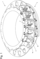
- the Figure 1 shows a section of a container treatment plant from the prior art, which corresponds in many respects to the blow molding plant according to the invention. Accordingly, a rotatably driven carrier 1 is provided, with a plurality of treatment modules 2 arranged in the circumferential direction on the carrier 1, which are designed as blow modules.
- Each treatment module 2 consists of a blow mold 3, which is assigned to a valve device and which is in the Figure 1 is not shown in more detail.
- This valve device makes it possible to apply a blowing fluid to the preforms made of a thermoplastic material arranged in the blow mold 3, so that they can be formed into beverage containers.
- the blow mold 3 consists of at least two blow mold parts 4a, 4b, with only a first blow mold part 4a being designed to be pivotable.
- the pivoting of the first blow mold part 4a serves to open and close the blow mold 3, whereby in the open position of the corresponding blow mold 3 a preform can be inserted into the blow mold 3 or a fully formed beverage container can be removed.
- the opening and closing of the blow mold 3 takes place via an actuator 5 designed as a curved guide with guide curves 5a, 5b, which are only arranged in sections along the circumference of the rotatable carrier 1, whereby this area is referred to as the transfer area.
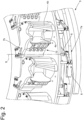
- the first blow mold part 4a is connected via a toggle lever arrangement 10 to an actuating shaft 6 designed to be rotatable about a pivot axis S.
- a linkage lever 7a is arranged, which has a guide roller arrangement 8, via which the linkage lever 7a engages in the guide curves 5a, 5b.
- the guide curves 5a, 5b are arranged opposite one another, so that the linkage lever 7a can be moved both radially inwards and can be pressed outwards, causing the blow mold 3 to open and close.
- the blow mold 3 can be opened and closed manually using an operating lever 7b.
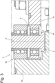
- the Figure 3 shows the guide roller arrangement 8 with a lower first guide roller 8a and an upper second guide roller 8b, which are arranged in a common axis of rotation D.
- the first guide roller is designed such that it rolls on a first, radially inner guide curve 5a, while the second guide roller 8b rolls on a second, radially outer guide curve 5b.
- the guide roller arrangement 8 is guided in the adjusting cam arrangement 5 without slipping, or that there is no gap between the guide cam arrangement 5 and the guide roller arrangement 8 in a radial direction.
- a ring element 9 which is made of an elastically deformable material and which, in the case of the Figure 3 shown embodiment is arranged radially on the outside of the first guide roller 8a. Accordingly, this ring element 9 lies directly on the first guide curve 5a and causes both guide rollers 8a, 8b to be pressed against the associated guide curves 5a, 5b with a sufficiently large contact pressure.
- the ring element 9 being designed with an oversize outside the guide curve arrangement 5, or by the first guide roller 8a outside the guide curve arrangement 5 drawing a radius which is smaller than the radius of the first guide curve 5a.
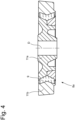
- the Figure 4 a guide roller 8a in the manner of a wheel tire is shown, wherein the ring element 9 is arranged between an inner and an outer ring roller 11a, 11b, so that in contrast to the Figure 3 In the embodiment shown, it is not the ring element 9 but rather the outer ring roller 11b that rests on the guide curve 5a.
- a first guide roller 8a and a second guide roller 8b are attached to the articulation lever 7a in a common axis of rotation D and together form the guide roller arrangement 8.
- the first guide roller 8a rolls on the inner guide curve 5a and the second guide roller 8b on the second guide curve 5b, with the second guide roller 8b now being assigned a ring element 9 made of an elastically deformable material, which in this case is part of a separate pressure roller 12 arranged below the second guide roller 8b.
- the ring element 9 rolls on the second guide curve 5b in a similar way to the second guide roller 8b and has a labyrinth-shaped section in the area of the ring element 9, which lies directly on the second guide roller 8b.
- the ring element 9 is pressed against the outer portion of the second guide roller 8b and causes the guide roller 8b to roll in a suitable manner and essentially without friction on the second guide curve 5b.
Landscapes
- Engineering & Computer Science (AREA)
- Manufacturing & Machinery (AREA)
- Mechanical Engineering (AREA)
- Blow-Moulding Or Thermoforming Of Plastics Or The Like (AREA)
Abstract
Description
- Die Erfindung betrifft eine Behälterbehandlungsanlage mit zumindest einer eine Vielzahl von Behandlungsmodulen aufweisenden Transportvorrichtung, wobei die Behandlungsmodule dazu eingerichtet sind, Behälter während eines Transports entlang eines Transportpfades zu behandeln und mit zumindest einem als Kurvenführung ausgebildeten Stellantrieb zum Steuern der Behandlungsmodule, wobei der Stellantrieb jeweils eine an den Behandlungsmodulen angeordnete Führungsrollenanordnung aufweist, wobei eine erste Führungsrolle mit einer ersten Führungskurve und eine zweite Führungsrolle mit einer gegenüberliegenden zweiten Führungskurve in Eingriff gebracht werden kann.
- Die Erfindung bezieht sich hierbei insbesondere auf Behälterbehandlungsanlagen aus dem Bereich der Lebensmittelindustrie insbesondere der Getränkeindustrie. Entsprechend handelt es sich bei den zu behandelnden Behältern um Getränkebehälter z. B. um Getränkeflaschen aus Glas oder Kunststoff. Bei den Behältern kann es sich darüber hinaus auch um sogenannte Vorformlinge bzw. Preforms handeln, welche innerhalb der Behälterbehandlungsanlage erst zu Getränkebehältern ausgeformt werden. Dies erfolgt üblicherweise über eine sogenannte Blasvorrichtung insbesondere Streckblasvorrichtung, bei der im Zuge der Behandlung ein Blasfluid z. B. Druckluft in die Vorformlinge eingeleitet wird. welches die Vorformlinge derart mit Druck beaufschlagt, dass diese an eine Blasform herangedrückt werden.
- Die Blasform weist hierzu eine Innenkavität auf, welche der Form des zu fertigenden Behälters entspricht. In diesem Zusammenhang ist anzumerken, dass die Vorformlinge in der Regel einen bereits fertig ausgebildeten Kopfabschnitt aufweisen, welcher während des Umformens außerhalb der Blasform angeordnet ist und welcher bereits über ein Außengewinde zur Aufnahme einer Verschlusskappe aufweist. Anstelle von Druckluft eignet sich auch ein flüssiges Blasfluid zum Einbringen in die Behälter. Hierbei handelt es sich insbesondere um ein flüssiges Füllmedium z. B. ein Getränk, wodurch einerseits durch Einbringen des Füllmediums die Behälter plastisch verformt werden und zugleich das Füllmedium innerhalb des Behälters angeordnet werden kann. Ein solches Verfahren wird auch als Formfill-Verfahren bezeichnet.
- Grundsätzlich bezieht sich die Erfindung auf alle Arten von Behandlungsanlagen, in welchen eine Behandlung der Behälter erfolgt. Diese Behandlung können die Behälter beispielsweise in mechanischer, optischer oder sonstiger Art und Weise behandelt werden, so dass die Behandlung nicht ausschließlich auf eine Blasumformung beschränkt ist.
- Im Rahmen derartiger Behandlungsanlagen ist es bekannt, eine Vielzahl von verschiedenen Steueraktionen mithilfe von Stellantrieben durchzuführen, welche als Kurvenführung ausgebildet sind. In diesem Zusammenhang ist mit Steuern gemeint, dass in irgendeiner Form die Behandlungsmodule oder die über die Behandlungsmodule geführten Behälter beeinflusst werden. Beispielsweise eignen sich derartige Stellantriebe zum Öffnen und Schließen der Blasformen.
- Die Kurvenführung besteht hierbei einerseits aus zumindest einer Führungsrolle und einer zugeordneten Führungskurve, wobei die Führungsrolle im Zuge der Bewegung der Behandlungsmodule an der Führungskurve abrollen kann und entsprechend zumindest teilweise mit dieser in Eingriff steht. Die Führungskurve weist hierbei einen Kurvenverlauf auf, welcher eine Bewegung der Führungsrolle senkrecht zur Drehachse und senkrecht zur Bewegungsrichtung ermöglicht. Hierdurch lassen sich verschiedene Steueraktionen z. B. Stellaktionen rein mechanisch steuern, wodurch sich insbesondere eine geringe Fehleranfälligkeit ergibt, da aufgrund des festgelegten Konturverlaufs der Führungskurve allenfalls geringfügige Abweichungen im Steuerungsverlauf möglich sind. Um eine gegenläufige Steueraktion zu ermöglichen sind dann entsprechend zwei Führungskurven vorgesehen, welche entlang gegenüberliegender Führungskurven abrollbar sind. Beispielsweise ist es hierdurch möglich, ein Öffnen und ein Schließen einer Blasform zu ermöglichen, wobei die unterschiedlichen Bewegungen durch unterschiedliche Führungsrollen und zugeordnete Führungskurven bewegt wird.
- Wenngleich sich die Führungskurven lediglich über einen gewissen Abschnitt des Transportpfades erstrecken, so ist insbesondere der Übergabebereich zwischen diesen beiden Führungskurven von Bedeutung, da die Führungsrollen zumindest für einen kurzen Abschnitt kraftfrei bzw. mit einem Schlupf zwischen den beiden Führungskurven angeordnet sein können. Dies hat allerdings zur Folge, dass zumindest für ein diesen Abschnitt das mangelnde Abrollverhalten zu einem erhöhten Reibungsverschleiß führen können, welchem in der Vergangenheit beispielsweise damit begegnet wurde, dass sowohl die Führungsrollen als auch die zugeordneten Stellkurven an den Oberflächen gehärtet wurden, um den Verschleiß zu minimieren.
- Gerade bei besonders großen Behälterbehandlungsanlagen, welche einen hohen Behälterdurchsatz von zumindest 54.000 Behälter pro Stunde ermöglichen sollen, sind diese Maßnahmen jedoch nicht ausreichend, um den Betrieb über einen langen Zeitraum aufrechterhalten zu können.
- Vor diesem Hintergrund liegt der vorliegenden Erfindung die Aufgabe zugrunde, eine Behälterbehandlungsanlage anzugeben, welche einen verschleißarmen Betrieb und zugleich eine zuverlässige Steuerung der Behandlungsmodule ermöglicht.
- Gegenstand und Lösung dieser Aufgabe ist eine Behälterbehandlungsanlage gemäß Patentanspruch 1. Erfindungsgemäß ist vorgesehen, dass die Führungsrollenanordnung zumindest ein elastisch verformbares Ringelement aufweist. Mithilfe dieses elastisch verformbaren Ringelementes ist es möglich, die Führungsrollen der Führungsrollenanordnung über weite Bereiche der Führungskurven mit einer vordefinierten Anpresskraft zu betreiben. Die vordefinierte Anpresskraft liegt hierbei bevorzugt zumindest zwischen 120 und 300 N.
- Die Erfindung geht von der Kenntnis aus, dass mithilfe eines solchen Ringelementes sichergestellt werden kann, dass auch im Fall von Drehmomentschwankungen oder anderweitigen Krafteinwirkungen auf die Führungskurve stets eine minimale Anpresskraft gewährleistet werden kann, welche auch beim Übergang zwischen den einzelnen Führungskurven wirkt und hierdurch ein reibungsarmes Abrollen der Führungsrollen an der entsprechend zugeordneten Führungskurve ermöglicht.
- Die erforderliche Anpresskraft kann hierbei gemäß einer bevorzugten Ausgestaltung dadurch erreicht werden, dass das elastische Ringelement in einem an die erste und/oder die zweite Führungskurve angepressten Zustand gegenüber einem kraftfreien Zustand zwischen 0,05 und 0,8 mm verformt wird. Entsprechend wird das Ringelement zumindest an eine der Führungskurven angedrückt und hierdurch verformt. Im Zuge der Verformung entsteht eine Anpresskraft, welche ausreichend ist, damit die Führungsrollen möglichst schlupffrei an der entsprechend zugeordneten Führungsrolle abrollen können.
- Für eine solche Ausgestaltung ist es insbesondere sinnvoll, wenn das Material des Ringelementes ausgewählt ist aus der Gruppe Gummi, thermoplastisches Elastomere, Polyurethane und Polyamide. Mithilfe dieser Materialien und der zuvor erwähnten Verformung hat sich der Betrieb als besonders wirkungsvoll erwiesen.
- Eine bevorzugte Weiterbildung der Erfindung sieht ferner vor, dass die zweite Führungsrolle oberhalb der ersten Führungsrolle in einer gemeinsamen Drehachse angeordnet ist, wobei das elastische Ringelement an einer der Führungsrollen angeordnet oder gebildet ist. Entsprechend ist auch die zweite Führungskurve oberhalb der ersten Führungskurve angeordnet, wobei die entsprechenden Führungsrollen selbstverständlich lediglich mit der ihr zugeordneten Führungskurve in Eingriff gebracht werden können, um ein Blockieren der Abrollbewegung zu verhindern. Durch die Anordnung des elastischen Ringelementes unmittelbar an einer der Führungsrollen oder durch die Bildung des Ringelementes an einer der Führungsrollen kann im ausreichenden Maße sichergestellt werden, dass im Zuge der elastischen Verformung die Anpresskraft eine schlupffreie Führung der Führungsrollen an der ihr zugeordneten Führungskurve ermöglicht.
- Bezüglich der Ausgestaltung der Führungsrollen und der Lage des elastischen verformbaren Ringelementes eignen sich grundsätzlich verschiedene Ausgestaltungsformen, welche im Rahmen der erfindungsgemäßen Behälterbehandlungsanlage eingesetzt werden können. Beispielsweise kann das Ringelement radial außerhalb an einer der Führungsrollen, insbesondere an der ersten Führungsrolle, angeordnet sein. Gemäß einer solchen Ausgestaltung umschließt das Ringelement die Führungsrolle und bildet somit den Abschnitt, welcher unmittelbar an der Führungskurve anliegt. Vorzugsweise handelt es sich hierbei um die erste Führungsrolle bzw. die erste Führungskurve. Eine solche Ausgestaltung ist dann sinnvoll, wenn die zu überbringende Stellaktion oberhalb der Führungsrollenanordnung erfolgt. In diesem Fall wirken auf die erste und damit untere Führungsrolle geringere Lasten, sodass gerade in diesem Bereich die Anordnung des Ringelementes besonders sinnvoll ist. Selbstverständlich kann aber auch eine genau umgekehrte Anordnung sinnvoll sein, wenn die zu erbringende Steueraktion unterhalb der Führungsrollenanordnung erfolgt. In diesem Fall ist dann das elastische Ringelement bevorzugt an der zweiten Führungsrolle gebildet. Durch Auswahl eines geeigneten Materials kann bei einer solchen Ausgestaltung neben einer ausreichenden Anpresskraft auch der Haftreibungskoeffizient in geeigneter Art und Weise hochgesetzt werden, da das Ringelement, wie bereits zuvor erläutert, unmittelbar an der Führungskurve anliegt. Hierdurch wird die Gefahr eines Entlangschleifens der Führungsrolle an der Führungskurve auch im Bereich niedriger Anpresskräfte wirksam verringert.
- Gemäß einer alternativen oder ergänzenden Ausgestaltung weist zumindest eine der Führungsrollen eine radial innenliegende erste und eine radial außenliegende zweite Ringrolle auf, wobei das elastische Ringelement zwischen der ersten und der zweiten Ringrolle angeordnet ist. Eine solche Ausgestaltung ähnelt dabei einem sogenannten Radreifen, welcher beispielsweise auch aus der Eisenbahntechnik bekannt ist. Während die erste Ringrolle maßgeblich für die Stabilität verantwortlich ist, kann die zweite Ringrolle hinsichtlich des Materials in Ausgestaltung bezüglich des Abrollverhaltens an der Führungskurve ausgewählt werden. Das elastische Ringelement stellt dann eine Verbindung zwischen der inneren ersten und der äußeren zweiten Ringrolle her und bewirkt einerseits eine Federung und andererseits eine Vorspannung.
- Eine alternative oder ergänzende Ausgestaltung sieht ferner vor, dass das elastische Ringelement an einer Anpressrolle gebildet ist, welche unmittelbar an zumindest einer der Führungsrollen in einer gemeinsamen Drehachse angrenzt und wobei das elastische Ringelement derart ausgebildet ist, dass es im Zuge einer Verformung zumindest teilweise reibschlüssig mit der zumindest einen angrenzenden Führungsrolle verbunden ist. Insbesondere ist die Anpressrolle unterhalb der ersten oder oberhalb der zweiten Führungsrolle angeordnet, wobei die Anordnung sich insbesondere daran richtet, wo die Steueraktion erfolgt. Insbesondere bei einer Steueraktion oberhalb der Führungsrollenanordnung ist eine Anordnung der Anpressrolle unterhalb der ersten Führungsrolle bevorzugt. Bei einer Steueraktion unterhalb der Führungsanordnung ist die Anpressrolle bevorzugt oberhalb der zweiten Führungsrolle angeordnet. Gemäß einer solchen Ausgestaltung verformt sich die Anpressrolle durch Eingreifen bzw. Abrollen an der zugeordneten Führungskurve insbesondere in eine radiale Richtung, wobei zugleich auch in axialer Richtung eine gewisse Verformung erfolgt. Hierdurch liegt sich die Anpressrolle an der zugeordneten Führungsrolle an und bewirkt einen Reibschluss, wodurch die Führungsrolle mitrotiert. Folglich wird durch die Verformung der Anpressrolle die Rotation der Anpressrolle auf die zumindest eine Führungsrolle übertragen. Dies kann Beispielfall dadurch erfolgen, dass die Anpressrolle radial außenliegend im Querschnitt labyrinthförmig ausgebildet ist, sodass dieser Abschnitt durch Aufbringen einer Querkraft, insbesondere einer Kraft in radialen Richtung, in axiale Richtung aufgewölbt wird. Dieser Abschnitt schließt üblicherweise an ein bezüglich der Drehachse radial innenliegendes Anpresswälzlager an, über das sichergestellt wird, dass das entsprechend ausgebildete elastische Ringelement an der Führungskurve abrollt.
- Wie bereits eingangs erläutert, ist es ausreichend, wenn die Führungskurven lediglich jeweils entlang eines sich überschneidenden und sich in Umfangsrichtung erstreckenden Führungsabschnittes angeordnet sind. Entsprechend müssen die Führungskurven nicht beide jeweils den gesamten Transportpfad abbilden. Vielmehr reicht es aus, wenn der Transportpfad lediglich in einem Abschnitt durch eine der Führungskurven gebildet ist. Selbstverständlich bilden aber beide Führungskurven gemeinsam den Transportpfad ab, wobei der Transportpfad gemäß einer bevorzugten Ausgestaltungsweise auch umlaufend ausgebildet ist.
- Eine Weiterbildung der Erfindung sieht ferner vor, dass die Führungsrollenanordnung über 70 % der Länge, bevorzugt über zumindest 80 % der Länge des Transportpfades schlupffrei geführt ist. Entsprechend ist zumindest eine der Führungsrollen stets mit einer der Führungskurven in Eingriff und rollt an dieser ab, wobei durch das Ringelement sichergestellt wird, dass die Führungsrollen stets mit einer ausreichenden Anpresskraft an den Führungskurven anliegen und wobei durch die schlupffreie Führung Schläge der Führungsrollen an die Führungskurve z. B. beim Flankenwechsel verhindert wird.
- Die Erfindung ist grundsätzlich nicht auf eine bestimmte Form der Behälterbehandlungsanlage beschränkt, so kann die Behälterbehandlungsanlage beispielsweise eine Füllvorrichtung, eine Verschließvorrichtung oder eine Etikettiervorrichtung aufweisen. Besonders bevorzugt ist jedoch eine Ausgestaltung, bei der die Behälterbehandlungsanlage eine Blasvorrichtungen, insbesondere eine Streckblasvorrichtung, zum Umformen von Vorformlingen zu Getränkeflaschen aufweist. Hierbei ist entsprechend eine Blasvorrichtungen mit einem rotierbaren Träger und einer Vielzahl von in Umfangsrichtung an dem Träger angeordneten Behandlungsmodulen vorgesehen, welche als Blasmodule ausgebildet sind und jeweils eine Blasform aus zumindest zwei Blasformteilen aufweisen. Den Blasformen ist darüber hinaus üblicherweise eine Ventilvorrichtung zugeordnet, über die das entsprechende Blasfluid z. B. Druckluft oder ein flüssiges Füllmedium in die Behälter eingeführt werden kann. Gemäß einer üblichen Ausgestaltung von Blasvorrichtungen sind die Ventileinrichtungen stationär zu den Blasformen angeordnet und rotieren somit ebenfalls an dem Träger mit. Die Führungskurven können dann entsprechend entlang des Umfangs des rotierbaren Trägers stationär angeordnet sein, sodass die Führungsrollen im Zuge einer Rotation des Trägers an den Führungskurven abrollen können.
- Ausgehend von einer solchen Ausgestaltung eignet sich der Einsatz eines entsprechenden Stellantriebes für verschiedene Anwendungszwecke. Gemäß einer ersten Ausgestaltungsform ist der Stellantrieb dazu eingerichtet, die Blasformen durch Verschwenken der Blasformteile zueinander zu Öffnen oder zu Schließen. Hierzu sind die Blasformteile üblicherweise zueinander verschwenkbar ausgebildet, wobei in einem geöffneten Zustand ein Vorformling eingesetzt oder der bereits fertig ausgebildete Behälter in Form einer Getränkeflasche entnommen werden kann. Die eigentliche Beanspruchung mit einem Blasfluid erfolgt entsprechend in einem Schließzustand. Gemäß einer üblichen Ausgestaltung weist die Blasvorrichtung zumindest zwei verschwenkbare Blasformteile auf, welche insbesondere die seitlichen Wandungen der Behälter bilden. Gemäß einer bevorzugten Ausgestaltung kann darüber hinaus auch ein unteres Blasformteil oder Bodenteil vorgesehen sein, welches die Ausgestaltung des Bodens definiert. Zum Verschwenken der Blasformteile ist dann entsprechend der Stellantrieb vorgesehen, wobei gerade im Rahmen eines solchen Anwendungszweckes vergleichsweise große Kräfte notwendig sind, um die Blasformteile zu bewegen.
- Eine bevorzugte Ausgestaltung sieht daher in diesem Zusammenhang vor, dass die Blasformteile über eine Hebelanordnung, insbesondere eine Kniehebelanordnung, verschwenkbar zueinander eingerichtet, wobei die Hebelanordnung an eine rotierbar um eine Schwenkachse ausgebildeten Betätigungswelle anschließt, an welcher ein Anlenkhebel zum Betätigen der Hebelanordnung angeordnet ist und wobei die Führungsrollenanordnung an dem Anlenkhebel angeordnet ist. Gemäß der üblichen Ausgestaltung einer solchen Blasvorrichtung bewirkt die Kurvenführung, dass die Führungsrollen entweder bezogen auf den Träger radial nach innen oder nach außen gedrückt werden, wobei einerseits ein Öffnen und andererseits ein Schließen der Blasform bewirkt wird. Grundsätzlich ist es ausreichend, wenn die Führungskurven lediglich in einem Übergangsbereich angeordnet ist, in welchem ein Öffnen und Schließen der Blasform erforderlich ist. Darüber hinaus kann über die Hebelanordnung aber auch ein Zuhalten der Blasform bewirkt werden, sodass dann entsprechend entlang des gesamten Umfangs des Trägers zumindest eine Führungskurve vorzusehen ist.
- Gerade aufgrund der großen Kräfte, die bei einer solchen Ausgestaltung auf die Führungsrollen wirken, ist die erfindungsgemäße Ausbildung mit einem elastischen Ringelement besonders von Vorteil, da insbesondere auf die Führungsrollen einwirkende Stöße zu einem gewissen Maße aufgenommen werden können.
- Eine ergänzende oder alternative Ausgestaltung der Erfindung sieht ferner vor, dass die Blasmodule jeweils eine der Blasform zugeordnete Ventileinrichtung zum Einbringen eines Blasfluids in die Behälter aufweisen, wobei die Ventileinrichtungen jeweils eine Reckstange aufweisen, über welche eine Längung der Behälter entlang der Behälterachse bewirkt wird. Eine solche Ausgestaltung ist insbesondere dann sinnvoll, wenn es sich bei den Behältern um Behälter aus Polyethylenterephthalat handelt. Diese Reckstange wird entlang der Behälterachse verfahren. Dies erfolgt nunmehr erfindungsgemäß mit einem zuvor beschriebenen Stellantrieb.
- Eine weitere Alternative oder ergänzende Ausgestaltung sieht vor, dass der Blasvorrichtung eine Heizvorrichtung mit einer umlaufenden Kette und einer Vielzahl von Umfangsrichtung an der Kette angeordneten Behandlungsmodulen vorgeschaltet ist. Über eine entsprechende Heizvorrichtung erfolgt das Erwärmen und Aufweichen der Vorformlinge, sodass die plastische Verformung in einfacher und effektiver Art und Weise durchgeführt werden kann. Hierzu werden die Behälter an Transportdornen angeordnet, welche üblicherweise über einen Kettenantrieb entlang von Heizeinrichtungen bewegt werden. Über diese Heizeinrichtungen erfolgt das Aufprägen von Strahlungswärme. Diese Transportdorne sind vorzugsweise entlang der Behälterachse verfahrbar angeordnet, wobei durch diese Bewegung die Transportdorne in die Behältermündung eingeführt und dort klemmend angeordnet werden können. Auch diese Bewegung kann nunmehr über einen entsprechend eingerichteten Stellantrieb bewirkt werden.
- Grundsätzlich sind auch weitere Anwendungszwecke im Rahmen der Erfindung möglich. Gerade im Rahmen von Blasvorrichtungen kann mithilfe einer solchen Ausgestaltung auch ein Verschließen der Blasform bewirkt werden, wobei dann mithilfe des Stellantriebs ein separater Schließmechanismus verstellt wird.
- Darüber hinaus kann die Behälterbehandlungsanlage auch eine Etikettiervorrichtung zum Etikettieren der Behälter und/oder eine Verschließvorrichtung zum Verschließen der Behälter aufweisen, wobei der Stellantrieb dann zum Steuern der Etikettiervorrichtung und/oder der Verschließvorrichtung eingerichtet sein kann.
- Im Folgenden wird die Erfindung anhand eines exemplarischen und nicht beschränkten Ausführungsbeispiels näher erläutert. Die Figuren zeigen:
- Fig. 1
- ein Ausschnitt aus einer Behälterbehandlungsanlage mit Blasvorrichtung aus dem Stand der Technik in einer isometrischen Ansicht
- Fig. 2
- ein Ausschnitt aus der Darstellung gemäß der
Figur 1 im Bereich der einzelnen Blasmodule - Fig. 3
- eine Führungsrollenanordnung mit radial außenliegendem Ringelement
- Fig. 4
- eine alternative Führungsrollenanordnung mit Ringelement zwischen einer inneren und einer äußeren Ringrolle
- Fig. 5
- eine alternative Führungsrollenanordnung mit separater Anpressrolle
- Die
Figur 1 zeigt einen Ausschnitt aus einer Behälterbehandlungsanlage aus dem Stand der Technik, welche in vielerlei Hinsicht mit der erfindungsgemäßen Blasanlage übereinstimmt. Demnach ist ein rotierbar angetriebener Träger 1 vorgesehen, wobei eine Vielzahl von Behandlungsmodule 2 in Umfangsrichtung an dem Träger 1 angeordnet sind, welche als Blasmodule ausgebildet sind. - Jedes Behandlungsmodul 2 besteht aus einer Blasform 3, welcher einer Ventileinrichtung zugeordnet ist und welche in der
Figur 1 nicht näher dargestellt ist. Über diese Ventileinrichtung ist es möglich, die in der Blasform 3 angeordneten Vorformlinge aus einem thermoplastischen Material mit einem Blasfluid zu beaufschlagen, so dass eine Ausformung zu Getränkebehältern erfolgen kann. Die Blasform 3 besteht aus zumindest zwei Blasformteilen 4a, 4b, wobei lediglich ein erstes Blasformteil 4a verschwenkbar ausgebildet ist. - Das Verschwenken des ersten Blasformteils 4a dient dem Öffnen und Schließen der Blasform 3, wobei in der Öffnungsstellung der entsprechenden Blasform 3 ein Vorformling in die Blasform 3 eingesetzt bzw. ein fertig ausgebildeter Getränkebehälter entnommen werden kann. Das Öffnen und Schließen der Blasform 3 erfolgt über einen als Kurvenführung ausgebildeten Stellantrieb 5 mit Führungskurven 5a, 5b, welche lediglich abschnittsweise entlang des Umfangs des rotierbaren Trägers 1 angeordnet sind, wobei dieser Bereich als Übergabebereich bezeichnet wird.
- Die genaue Funktionsweise des Schwenkmechanismus geht insbesondere aus der
Figur 2 deutlich hervor. Demnach schließt das erste Blasformteil 4a über eine Kniehebelanordnung 10 an eine um eine Schwenkachse S rotierbar ausgebildete Betätigungswelle 6 an. An dieser Betätigungswelle 6 ist wiederum endseitig ein Anlenkhebel 7a angeordnet, welcher eine Führungsrollenanordnung 8 aufweist, über welche der Anlenkhebel 7a in die Führungskurven 5a, 5b eingreift. Die Führungskurven 5a, 5b sind gegenüberliegend angeordnet, sodass der Anlenkhebel 7a bezogen auf den Träger 1 sowohl radial nach innen als auch nach außen gedrückt werden kann, wodurch ein Öffnen und Schließen der Blasform 3 bewirkt wird. Mit Hilfe eines Betätigungshebels 7b kann ein manuelles Öffnen und Schließen der Blasform 3 erfolgen. - Die
Figur 3 zeigt die Führungsrollenanordnung 8 mit einer unteren ersten Führungsrolle 8a und einer oberen zweiten Führungsrolle 8b, welche in einer gemeinsamen Drehachse D angeordnet sind. Die erste Führungsrolle ist hierbei so ausgebildet, dass diese an einer ersten, radial innenliegenden Führungskurve 5a abrollt, während die zweite Führungsrolle 8b an einer zweiten, radial außenliegenden Führungskurve 5b abrollt. - Anhand der
Figur 3 ist deutlich zu erkennen, dass die Führungsrollenanordnung 8 schlupffrei in der Stellkurvenanordnung 5 geführt ist, bzw. dass bezüglich einer radialen Richtung kein Spalt zwischen der Führungskurvenanordnung 5 und der Führungsrollenanordnung 8 vorliegt. Dies wird gewährleistet durch ein Ringelement 9, welches aus einem elastisch verformbaren Material gebildet ist und welches im Fall der in derFigur 3 gezeigten Ausgestaltungsform radial außenliegend an der ersten Führungsrolle 8a angeordnet ist. Dementsprechend liegt dieses Ringelement 9 unmittelbar an der ersten Führungskurve 5a an und bewirkt, dass beide Führungsrollen 8a, 8b mit einem ausreichend großen Anpressdruck an die zugeordneten Führungskurven 5a, 5b gepresst werden. Dies wird insbesondere dadurch erreicht, dass das Ringelement 9 außerhalb der Führungskurvenanordnung 5 mit einem Übermaß ausgebildet ist, bzw. dass die erste Führungsrolle 8a außerhalb der Führungskurvenanordnung 5 einen Radius zeichnet, welcher kleiner ist als der Radius der ersten Führungskurve 5a. - Gemäß einer alternativen Ausgestaltung ist in der
Figur 4 eine Führungsrolle 8a nach Art eines Radreifens gezeigt, wobei das Ringelement 9 zwischen einer inneren und einer äußeren Ringrolle 11a, 11b angeordnet ist, sodass im Gegensatz zu der in derFigur 3 gezeigten Ausgestaltungsform nicht das Ringelement 9 sondern vielmehr die äußere Ringrolle 11b an der Führungskurve 5a anliegt. - Auch gemäß der in der
Figur 5 gezeigten Ausgestaltungsform sind eine erste Führungsrolle 8a und eine zweite Führungsrolle 8b an dem Anlenkhebel 7a in einer gemeinsamen Drehachse D befestigt und bilden gemeinsam die Führungsrollenanordnung 8. Die erste Führungsrolle 8a rollt an der inneren Führungskurve 5a und die zweite Führungsrolle 8b an der zweiten Führungskurve 5b ab, wobei nunmehr der zweiten Führungsrolle 8b ein Ringelement 9 aus einem elastisch verformbaren Material zugeordnet ist, welches in diesem Fall Teil einer separaten unterhalb der zweiten Führungsrolle 8b angeordneten Anpressrolle 12 ist. Das Ringelement 9 rollt hierbei analog zu der zweiten Führungsrolle 8b an der zweiten Führungskurve 5b ab und weist einen labyrinthförmigen Abschnitt im Bereich des Ringelementes 9 auf, welcher unmittelbar an der zweiten Führungsrolle 8b anliegt. Durch Einwirken einer radialen Kraft durch die zweite Führungskurve 5b wird das Ringelement 9 gegen den äußeren Abschnitt der zweiten Führungsrolle 8b gedrückt und bewirkt, dass die Führungsrolle 8b in geeigneter Art und Weise und im wesentlichen reibungsfrei an der zweiten Führungskurve 5b abrollt. -
- 1
- Träger
- 2
- Blasmodul
- 3
- Blasform
- 4a, 4b
- Blasformteile
- 5
- Stellantrieb
- 5a
- erste Führungskurve
- 5b
- zweite Führungskurve
- 6
- Betätigungswelle
- 7a
- Anlenkhebel
- 7b
- Betätigungshebel
- 8
- Führungsrollenanordnung
- 8a
- erste Führungsrolle
- 8b
- zweite Führungsrolle
- 9
- Ringelement
- 10
- Kniehebelanordnung
- 11a
- innere Ringrolle
- 11b
- äußere Ringrolle
- 12
- Anpressrolle
- D
- Drehachse
- S
- Schwenkachse
Claims (14)
- Behälterbehandlungsanlage mit zumindest einer eine Vielzahl von Behandlungsmodulen (2) aufweisenden Transportvorrichtung, wobei die Behandlungsmodule (2) dazu eingerichtet sind, Behälter während eines Transports entlang eines Transportpfades zu behandeln und mit zumindest einem als Kurvenführung ausgebildeten Stellantrieb (5) zum Steuern der Behandlungsmodule (2), wobei der Stellantrieb (5) jeweils eine an den Behandlungsmodulen (2) angeordnete Führungsrollenanordnung (8) aufweist, wobei eine erste Führungsrolle (8a) mit einer ersten Führungskurve (5a) und eine zweite Führungsrolle (8b) mit einer gegenüberliegenden zweiten Führungskurve (5b) in Eingriff gebracht werden kann,
dadurch gekennzeichnet, dass
die Führungsrollenanordnung (8) zumindest ein elastisch verformbares Ringelement (9) aufweist. - Behälterbehandlungsanlage nach einem der vorangegangenen Ansprüche, dadurch gekennzeichnet, dass das elastische Ringelement (9) in einem an die erste und/oder die zweite Führungskurve (8a, 8b) angepressten Zustand gegenüber einem kraftfreien Zustand zwischen 0,05 und 0,8 mm verformt ist.
- Behälterbehandlungsanlage nach einem der vorangegangenen Ansprüche, dadurch gekennzeichnet, dass die zweite Führungsrolle (8b) oberhalb der ersten Führungsrolle (8a) in einer gemeinsamen Drehachse (D) angeordnet ist, wobei das elastische Ringelement (9) an einer der Führungsrollen (8a, 8b) angeordnet oder gebildet ist.
- Behälterbehandlungsanlage nach einem der vorangegangenen Ansprüche, dadurch gekennzeichnet, dass das elastische Ringelement (9) radial außerhalb an einer der Führungsrollen (8a, 8b), insbesondere an der zweiten Führungsrolle (8b), angeordnet ist.
- Behälterbehandlungsanlage nach einem der vorangegangenen Ansprüche 1 bis 3, dadurch gekennzeichnet, dass eine der Führungsrollen (8a, 8b) eine radial innenliegende erste und eine radial außenliegende zweite Ringrolle (11a, 11b) aufweist, wobei das elastische Ringelement (9) zwischen der ersten und der zweiten Ringrolle (11a, 11b) angeordnet ist.
- Behälterbehandlungsanlage nach einem der vorangegangenen Ansprüche, dadurch gekennzeichnet, dass das elastische Ringelement (9) an einer Anpressrolle (12) gebildet ist, welche unmittelbar an zumindest eine der Führungsrollen (8a, 8b) in einer gemeinsamen Drehachse (D) angrenzt und wobei das elastische Ringelement (9) derart ausgebildet ist, dass es im Zuge einer Verformung zumindest teilweise reibschlüssig mit der zumindest einen angrenzenden Führungsrolle (8a, 8b) verbunden ist.
- Behälterbehandlungsanlage nach Anspruch 6, dadurch gekennzeichnet, dass die Anpressrolle (12) unterhalb der ersten und/oder oberhalb der zweiten Führungsrolle (8a, 8b) angeordnet ist.
- Behälterbehandlungsanlage nach einem der vorangegangenen Ansprüche, dadurch gekennzeichnet, dass die Führungskurven (5a, 5b) lediglich jeweils entlang eines sich überschneidenden und sich in Umfangsrichtung erstreckenden Führungsabschnitts angeordnet sind.
- Behälterbehandlungsanlage nach Anspruch 8, dadurch gekennzeichnet, dass die Führungsrollenanordnung (8) zumindest über 80 % der Länge des Transportpfades schlupffrei geführt ist.
- Behälterbehandlungsanlage nach einem der vorangegangenen Ansprüche, dadurch gekennzeichnet, dass eine Blasvorrichtung mit einem rotierbaren Träger (1) und einer Vielzahl von in Umfangsrichtung an dem Träger (1) angeordneten Behandlungsmodulen (2) vorgesehen ist, welche als Blasmodule ausgebildet sind und jeweils eine Blasform (3) aus zumindest zwei Blasformteilen (4a, 4b) aufweisen.
- Behälterbehandlungsanlage nach Anspruch 10, dadurch gekennzeichnet, dass der Stellantrieb (5) dazu eingerichtet ist, die Blasformen (3) durch Verschwenken der Blasformteile (4a, 4b) zueinander zu Öffnen oder zu Schließen.
- Behälterbehandlungsanlage nach Anspruch 11, dadurch gekennzeichnet, dass die Blasformteile (4a, 4b) über eine Hebelanordnung verschwenkbar zueinander eingerichtet sind, wobei die Hebelanordnung an eine rotierbar um eine Schwenkachse (S) ausgebildete Betätigungswelle anschließt, an welcher ein Anlenkhebel (7a) zum Betätigen der Hebelanordnung angeordnet ist, und wobei die Führungsrollenanordnung an dem Anlenkhebel (7a) angeordnet ist.
- Behälterbehandlungsanlage nach einem der Ansprüche 10 oder 12, dadurch gekennzeichnet, dass die Blasmodule (2) jeweils eine den Blasformen (3) zugeordnete Ventileinrichtung zum Einbringen eines Blasfluids in die Behälter aufweisen und wobei die Ventileinrichtungen jeweils eine Reckstange aufweisen, und wobei der Stellantrieb dazu eingerichtet ist, die Reckstangen entlang einer Behälterachse zu verfahren.
- Behälterbehandlungsanlage nach einem Ansprüche 10 bis 12, dadurch gekennzeichnet, dass der Blasvorrichtung eine Heizvorrichtung mit einer umlaufenden Kette und einer Vielzahl von in Umfangsrichtung an der Kette angeordneten Behandlungsmodulen (2) vorgeschaltet ist, welche als Transportdorne zur Aufnahme der Behälter ausgebildet sind und entlang von Heizeinrichtungen bewegbar sind, wobei der Stellantrieb (5) dazu eingerichtet ist, die Transportdorne entlang einer Behälterachse zu verfahren.
Applications Claiming Priority (1)
| Application Number | Priority Date | Filing Date | Title |
|---|---|---|---|
| DE102023104677.2A DE102023104677A1 (de) | 2023-02-27 | 2023-02-27 | Blasanlage zum Umformen von Kunststoff-Vorformlingen |
Publications (2)
| Publication Number | Publication Date |
|---|---|
| EP4420858A1 true EP4420858A1 (de) | 2024-08-28 |
| EP4420858B1 EP4420858B1 (de) | 2025-11-05 |
Family
ID=89772199
Family Applications (1)
| Application Number | Title | Priority Date | Filing Date |
|---|---|---|---|
| EP24154418.8A Active EP4420858B1 (de) | 2023-02-27 | 2024-01-29 | Behälterbehandlungsanlage zum behandeln von behältern |
Country Status (2)
| Country | Link |
|---|---|
| EP (1) | EP4420858B1 (de) |
| DE (1) | DE102023104677A1 (de) |
Citations (5)
| Publication number | Priority date | Publication date | Assignee | Title |
|---|---|---|---|---|
| WO2003050438A1 (fr) * | 2001-12-12 | 2003-06-19 | Sidel | Dispositif de guidage a came et installation de moulage en faisant application |
| US20090011069A1 (en) * | 2005-12-16 | 2009-01-08 | Sidel Participations | Control Device Using a Follower Member and a Cam Path to Control an Element of a Machine for Processing Containers, and a Container Processor Machine Including Such a Device |
| DE102012104754A1 (de) * | 2012-06-01 | 2013-12-05 | Krones Ag | Blasformmaschine mit umlaufender Verriegelungskurve |
| US20180154571A1 (en) * | 2015-06-15 | 2018-06-07 | S.I.P.A. Societa' Industrializzazione Progettazione E Automazione S.P.A. | A blowing mold for blowing thermoplastic material containers |
| EP3386715B1 (de) * | 2015-12-10 | 2019-10-23 | Sidel Participations | Formeinheit, deren öffnung von einer welle mit einem torsionsdämpfer kontrolliert wird |
Family Cites Families (2)
| Publication number | Priority date | Publication date | Assignee | Title |
|---|---|---|---|---|
| US3514829A (en) * | 1968-06-27 | 1970-06-02 | Leland F Blatt | Rollers |
| JP4351244B2 (ja) * | 2006-11-29 | 2009-10-28 | 有限会社浜インターナショナル | ローラを用いた移動装置、およびローラの製造方法 |
-
2023
- 2023-02-27 DE DE102023104677.2A patent/DE102023104677A1/de active Pending
-
2024
- 2024-01-29 EP EP24154418.8A patent/EP4420858B1/de active Active
Patent Citations (5)
| Publication number | Priority date | Publication date | Assignee | Title |
|---|---|---|---|---|
| WO2003050438A1 (fr) * | 2001-12-12 | 2003-06-19 | Sidel | Dispositif de guidage a came et installation de moulage en faisant application |
| US20090011069A1 (en) * | 2005-12-16 | 2009-01-08 | Sidel Participations | Control Device Using a Follower Member and a Cam Path to Control an Element of a Machine for Processing Containers, and a Container Processor Machine Including Such a Device |
| DE102012104754A1 (de) * | 2012-06-01 | 2013-12-05 | Krones Ag | Blasformmaschine mit umlaufender Verriegelungskurve |
| US20180154571A1 (en) * | 2015-06-15 | 2018-06-07 | S.I.P.A. Societa' Industrializzazione Progettazione E Automazione S.P.A. | A blowing mold for blowing thermoplastic material containers |
| EP3386715B1 (de) * | 2015-12-10 | 2019-10-23 | Sidel Participations | Formeinheit, deren öffnung von einer welle mit einem torsionsdämpfer kontrolliert wird |
Also Published As
| Publication number | Publication date |
|---|---|
| EP4420858B1 (de) | 2025-11-05 |
| DE102023104677A1 (de) | 2024-08-29 |
Similar Documents
| Publication | Publication Date | Title |
|---|---|---|
| DE69616035T2 (de) | Vorrichtung zum herstellen von behältern durch blasformen von vorformlingen aus plastik | |
| DE2742693C2 (de) | Maschine zum Blasformen von Hohlkörpern, insbesondere von Flaschen, aus thermoplastischem Kunststoff | |
| DE102007032434B4 (de) | Blasvorrichtung zum Expandieren von Behältnissen | |
| EP3294525B1 (de) | Umformungsstation für blasformmaschinen ohne druckkissen | |
| EP2740582B1 (de) | Blasformmaschine und Blasformverfahren. | |
| DE69503657T2 (de) | Haltevorrichtung für vorformlinge | |
| DE102008037865A1 (de) | Transportvorrichtung | |
| WO2012130374A1 (de) | Verfahren und vorrichtung zur herstellung von behältern | |
| EP3706976B1 (de) | Form- und füllstation einer anlage zum herstellen von gefüllten behältern aus vorformlingen durch unter druck in den vorformling eingeleitetes füllgut | |
| EP4420858B1 (de) | Behälterbehandlungsanlage zum behandeln von behältern | |
| EP3912937A1 (de) | Vorrichtung zum vorgeben einer klammerarmposition und behältertransportvorrichtung | |
| EP3711925A1 (de) | Blasformmaschine mit doppelrückschlagventil | |
| EP2777912A1 (de) | Vorrichtung zum Behandeln von Behältnissen mit Kunststoffführungsrollen aus Polyamidimid | |
| EP3452264A1 (de) | Form- und füllstation einer anlage zum herstellen von gefüllten behältern aus vorformlingen durch unter druck in den vorformling eingeleitetes füllgut | |
| DE19504652A1 (de) | Vorrichtung zur Erzeugung eines Flüssigkeitsstrahls | |
| EP4554777A1 (de) | Greifeinrichtung für kombinierte behältnisausrichtungs- und -transporteinrichtung | |
| EP1630125A1 (de) | Vorrichtung zum Verschliessen von Flaschen oder dergl. Behälter | |
| DE102012104754A1 (de) | Blasformmaschine mit umlaufender Verriegelungskurve | |
| WO2025114021A1 (de) | Etikettiermaschine sowie verfahren zum betrieb | |
| DE102023105806A1 (de) | Blasanlage zum Umformen von Kunststoff-Vorformlingen | |
| WO2019092091A1 (de) | Vorrichtung und verfahren zum umformen von kunststoffvorformlingen zu kunststoffbehältnissen mit lagereinrichtung für den träger | |
| DE2233330A1 (de) | Vorrichtung zum anformen von verschlusskappen an behaeltermuendungen | |
| DE102023104190A1 (de) | Blasanlage zum Umformen von Kunststoffvorformlingen | |
| DE102023132955A1 (de) | Behälterhaltevorrichtung für eine Etikettiermaschine | |
| EP2628584A1 (de) | Transporteinrichtung und Transportverfahren für Behälterbehandlungsanlage sowie Blasmaschine |
Legal Events
| Date | Code | Title | Description |
|---|---|---|---|
| PUAI | Public reference made under article 153(3) epc to a published international application that has entered the european phase |
Free format text: ORIGINAL CODE: 0009012 |
|
| STAA | Information on the status of an ep patent application or granted ep patent |
Free format text: STATUS: THE APPLICATION HAS BEEN PUBLISHED |
|
| AK | Designated contracting states |
Kind code of ref document: A1 Designated state(s): AL AT BE BG CH CY CZ DE DK EE ES FI FR GB GR HR HU IE IS IT LI LT LU LV MC ME MK MT NL NO PL PT RO RS SE SI SK SM TR |
|
| STAA | Information on the status of an ep patent application or granted ep patent |
Free format text: STATUS: REQUEST FOR EXAMINATION WAS MADE |
|
| 17P | Request for examination filed |
Effective date: 20250228 |
|
| GRAP | Despatch of communication of intention to grant a patent |
Free format text: ORIGINAL CODE: EPIDOSNIGR1 |
|
| STAA | Information on the status of an ep patent application or granted ep patent |
Free format text: STATUS: GRANT OF PATENT IS INTENDED |
|
| RIC1 | Information provided on ipc code assigned before grant |
Ipc: B29C 49/56 20060101AFI20250618BHEP Ipc: B29C 49/06 20060101ALN20250618BHEP Ipc: B29C 49/12 20060101ALN20250618BHEP Ipc: B29C 49/36 20060101ALN20250618BHEP Ipc: B29C 49/58 20060101ALN20250618BHEP Ipc: B29C 49/46 20060101ALN20250618BHEP Ipc: B29C 49/48 20060101ALN20250618BHEP Ipc: B29K 67/00 20060101ALN20250618BHEP Ipc: B29L 31/00 20060101ALN20250618BHEP |
|
| INTG | Intention to grant announced |
Effective date: 20250707 |
|
| GRAS | Grant fee paid |
Free format text: ORIGINAL CODE: EPIDOSNIGR3 |
|
| GRAA | (expected) grant |
Free format text: ORIGINAL CODE: 0009210 |
|
| STAA | Information on the status of an ep patent application or granted ep patent |
Free format text: STATUS: THE PATENT HAS BEEN GRANTED |
|
| AK | Designated contracting states |
Kind code of ref document: B1 Designated state(s): AL AT BE BG CH CY CZ DE DK EE ES FI FR GB GR HR HU IE IS IT LI LT LU LV MC ME MK MT NL NO PL PT RO RS SE SI SK SM TR |
|
| REG | Reference to a national code |
Ref country code: CH Ref legal event code: F10 Free format text: ST27 STATUS EVENT CODE: U-0-0-F10-F00 (AS PROVIDED BY THE NATIONAL OFFICE) Effective date: 20251105 Ref country code: GB Ref legal event code: FG4D Free format text: NOT ENGLISH |
|
| REG | Reference to a national code |
Ref country code: DE Ref legal event code: R096 Ref document number: 502024000355 Country of ref document: DE |
|
| REG | Reference to a national code |
Ref country code: IE Ref legal event code: FG4D Free format text: LANGUAGE OF EP DOCUMENT: GERMAN |
|
| P01 | Opt-out of the competence of the unified patent court (upc) registered |
Free format text: CASE NUMBER: UPC_APP_0014560_4420858/2025 Effective date: 20251125 |
|
| REG | Reference to a national code |
Ref country code: NL Ref legal event code: MP Effective date: 20251105 |
|
| PG25 | Lapsed in a contracting state [announced via postgrant information from national office to epo] |
Ref country code: ES Free format text: LAPSE BECAUSE OF FAILURE TO SUBMIT A TRANSLATION OF THE DESCRIPTION OR TO PAY THE FEE WITHIN THE PRESCRIBED TIME-LIMIT Effective date: 20251105 |
|
| REG | Reference to a national code |
Ref country code: LT Ref legal event code: MG9D |
|
| PG25 | Lapsed in a contracting state [announced via postgrant information from national office to epo] |
Ref country code: NO Free format text: LAPSE BECAUSE OF FAILURE TO SUBMIT A TRANSLATION OF THE DESCRIPTION OR TO PAY THE FEE WITHIN THE PRESCRIBED TIME-LIMIT Effective date: 20260205 |
|
| PGFP | Annual fee paid to national office [announced via postgrant information from national office to epo] |
Ref country code: DE Payment date: 20260121 Year of fee payment: 3 |
|
| PG25 | Lapsed in a contracting state [announced via postgrant information from national office to epo] |
Ref country code: FI Free format text: LAPSE BECAUSE OF FAILURE TO SUBMIT A TRANSLATION OF THE DESCRIPTION OR TO PAY THE FEE WITHIN THE PRESCRIBED TIME-LIMIT Effective date: 20251105 Ref country code: HR Free format text: LAPSE BECAUSE OF FAILURE TO SUBMIT A TRANSLATION OF THE DESCRIPTION OR TO PAY THE FEE WITHIN THE PRESCRIBED TIME-LIMIT Effective date: 20251105 |
|
| PGFP | Annual fee paid to national office [announced via postgrant information from national office to epo] |
Ref country code: AT Payment date: 20260301 Year of fee payment: 3 |
|
| PGFP | Annual fee paid to national office [announced via postgrant information from national office to epo] |
Ref country code: IT Payment date: 20260131 Year of fee payment: 3 |
|
| PG25 | Lapsed in a contracting state [announced via postgrant information from national office to epo] |
Ref country code: NL Free format text: LAPSE BECAUSE OF FAILURE TO SUBMIT A TRANSLATION OF THE DESCRIPTION OR TO PAY THE FEE WITHIN THE PRESCRIBED TIME-LIMIT Effective date: 20251105 |
|
| PG25 | Lapsed in a contracting state [announced via postgrant information from national office to epo] |
Ref country code: RS Free format text: LAPSE BECAUSE OF FAILURE TO SUBMIT A TRANSLATION OF THE DESCRIPTION OR TO PAY THE FEE WITHIN THE PRESCRIBED TIME-LIMIT Effective date: 20260205 |
|
| PG25 | Lapsed in a contracting state [announced via postgrant information from national office to epo] |
Ref country code: IS Free format text: LAPSE BECAUSE OF FAILURE TO SUBMIT A TRANSLATION OF THE DESCRIPTION OR TO PAY THE FEE WITHIN THE PRESCRIBED TIME-LIMIT Effective date: 20260305 |
|
| PGFP | Annual fee paid to national office [announced via postgrant information from national office to epo] |
Ref country code: FR Payment date: 20260123 Year of fee payment: 3 |
|
| PG25 | Lapsed in a contracting state [announced via postgrant information from national office to epo] |
Ref country code: PT Free format text: LAPSE BECAUSE OF FAILURE TO SUBMIT A TRANSLATION OF THE DESCRIPTION OR TO PAY THE FEE WITHIN THE PRESCRIBED TIME-LIMIT Effective date: 20260305 |
|
| PG25 | Lapsed in a contracting state [announced via postgrant information from national office to epo] |
Ref country code: PL Free format text: LAPSE BECAUSE OF FAILURE TO SUBMIT A TRANSLATION OF THE DESCRIPTION OR TO PAY THE FEE WITHIN THE PRESCRIBED TIME-LIMIT Effective date: 20251105 |
|
| PG25 | Lapsed in a contracting state [announced via postgrant information from national office to epo] |
Ref country code: LV Free format text: LAPSE BECAUSE OF FAILURE TO SUBMIT A TRANSLATION OF THE DESCRIPTION OR TO PAY THE FEE WITHIN THE PRESCRIBED TIME-LIMIT Effective date: 20251105 |
|
| PG25 | Lapsed in a contracting state [announced via postgrant information from national office to epo] |
Ref country code: BG Free format text: LAPSE BECAUSE OF FAILURE TO SUBMIT A TRANSLATION OF THE DESCRIPTION OR TO PAY THE FEE WITHIN THE PRESCRIBED TIME-LIMIT Effective date: 20251105 |
|
| PG25 | Lapsed in a contracting state [announced via postgrant information from national office to epo] |
Ref country code: LT Free format text: LAPSE BECAUSE OF FAILURE TO SUBMIT A TRANSLATION OF THE DESCRIPTION OR TO PAY THE FEE WITHIN THE PRESCRIBED TIME-LIMIT Effective date: 20251105 |
|
| PG25 | Lapsed in a contracting state [announced via postgrant information from national office to epo] |
Ref country code: SM Free format text: LAPSE BECAUSE OF FAILURE TO SUBMIT A TRANSLATION OF THE DESCRIPTION OR TO PAY THE FEE WITHIN THE PRESCRIBED TIME-LIMIT Effective date: 20251105 |
|
| PG25 | Lapsed in a contracting state [announced via postgrant information from national office to epo] |
Ref country code: DK Free format text: LAPSE BECAUSE OF FAILURE TO SUBMIT A TRANSLATION OF THE DESCRIPTION OR TO PAY THE FEE WITHIN THE PRESCRIBED TIME-LIMIT Effective date: 20251105 |
|
| PG25 | Lapsed in a contracting state [announced via postgrant information from national office to epo] |
Ref country code: EE Free format text: LAPSE BECAUSE OF FAILURE TO SUBMIT A TRANSLATION OF THE DESCRIPTION OR TO PAY THE FEE WITHIN THE PRESCRIBED TIME-LIMIT Effective date: 20251105 |
|
| PG25 | Lapsed in a contracting state [announced via postgrant information from national office to epo] |
Ref country code: CZ Free format text: LAPSE BECAUSE OF FAILURE TO SUBMIT A TRANSLATION OF THE DESCRIPTION OR TO PAY THE FEE WITHIN THE PRESCRIBED TIME-LIMIT Effective date: 20251105 |
|
| PG25 | Lapsed in a contracting state [announced via postgrant information from national office to epo] |
Ref country code: SK Free format text: LAPSE BECAUSE OF FAILURE TO SUBMIT A TRANSLATION OF THE DESCRIPTION OR TO PAY THE FEE WITHIN THE PRESCRIBED TIME-LIMIT Effective date: 20251105 |
|
| PG25 | Lapsed in a contracting state [announced via postgrant information from national office to epo] |
Ref country code: SE Free format text: LAPSE BECAUSE OF FAILURE TO SUBMIT A TRANSLATION OF THE DESCRIPTION OR TO PAY THE FEE WITHIN THE PRESCRIBED TIME-LIMIT Effective date: 20251105 |