EP4420836A1 - Portable tray and installation method - Google Patents
Portable tray and installation method Download PDFInfo
- Publication number
- EP4420836A1 EP4420836A1 EP24158540.5A EP24158540A EP4420836A1 EP 4420836 A1 EP4420836 A1 EP 4420836A1 EP 24158540 A EP24158540 A EP 24158540A EP 4420836 A1 EP4420836 A1 EP 4420836A1
- Authority
- EP
- European Patent Office
- Prior art keywords
- tray
- shelf
- aircraft
- along
- bay
- Prior art date
- Legal status (The legal status is an assumption and is not a legal conclusion. Google has not performed a legal analysis and makes no representation as to the accuracy of the status listed.)
- Pending
Links
- 238000000034 method Methods 0.000 title claims description 18
- 238000009434 installation Methods 0.000 title description 2
- 230000000712 assembly Effects 0.000 claims abstract description 39
- 238000000429 assembly Methods 0.000 claims abstract description 39
- 210000005069 ears Anatomy 0.000 claims description 12
- 230000001419 dependent effect Effects 0.000 claims 2
- 239000000463 material Substances 0.000 abstract description 5
- 238000012423 maintenance Methods 0.000 abstract description 2
- 238000007689 inspection Methods 0.000 description 4
- 230000007246 mechanism Effects 0.000 description 3
- 238000010146 3D printing Methods 0.000 description 2
- 238000005452 bending Methods 0.000 description 2
- 238000012986 modification Methods 0.000 description 2
- 230000004048 modification Effects 0.000 description 2
- 239000000654 additive Substances 0.000 description 1
- 230000000996 additive effect Effects 0.000 description 1
- 229910052782 aluminium Inorganic materials 0.000 description 1
- XAGFODPZIPBFFR-UHFFFAOYSA-N aluminium Chemical compound [Al] XAGFODPZIPBFFR-UHFFFAOYSA-N 0.000 description 1
- 238000005266 casting Methods 0.000 description 1
- 238000010586 diagram Methods 0.000 description 1
- 229920001971 elastomer Polymers 0.000 description 1
- 239000000806 elastomer Substances 0.000 description 1
- 239000004744 fabric Substances 0.000 description 1
- 238000004519 manufacturing process Methods 0.000 description 1
- 229910052751 metal Inorganic materials 0.000 description 1
- 239000002184 metal Substances 0.000 description 1
- 230000000737 periodic effect Effects 0.000 description 1
- 238000002360 preparation method Methods 0.000 description 1
- 239000011208 reinforced composite material Substances 0.000 description 1
- 238000005096 rolling process Methods 0.000 description 1
- 239000007779 soft material Substances 0.000 description 1
- 239000007787 solid Substances 0.000 description 1
- 238000003860 storage Methods 0.000 description 1
- 239000013585 weight reducing agent Substances 0.000 description 1
- 238000003466 welding Methods 0.000 description 1
Images








Classifications
-
- B—PERFORMING OPERATIONS; TRANSPORTING
- B25—HAND TOOLS; PORTABLE POWER-DRIVEN TOOLS; MANIPULATORS
- B25H—WORKSHOP EQUIPMENT, e.g. FOR MARKING-OUT WORK; STORAGE MEANS FOR WORKSHOPS
- B25H3/00—Storage means or arrangements for workshops facilitating access to, or handling of, work tools or instruments
- B25H3/06—Trays
-
- B—PERFORMING OPERATIONS; TRANSPORTING
- B65—CONVEYING; PACKING; STORING; HANDLING THIN OR FILAMENTARY MATERIAL
- B65D—CONTAINERS FOR STORAGE OR TRANSPORT OF ARTICLES OR MATERIALS, e.g. BAGS, BARRELS, BOTTLES, BOXES, CANS, CARTONS, CRATES, DRUMS, JARS, TANKS, HOPPERS, FORWARDING CONTAINERS; ACCESSORIES, CLOSURES, OR FITTINGS THEREFOR; PACKAGING ELEMENTS; PACKAGES
- B65D19/00—Pallets or like platforms, with or without side walls, for supporting loads to be lifted or lowered
- B65D19/38—Details or accessories
-
- B—PERFORMING OPERATIONS; TRANSPORTING
- B60—VEHICLES IN GENERAL
- B60N—SEATS SPECIALLY ADAPTED FOR VEHICLES; VEHICLE PASSENGER ACCOMMODATION NOT OTHERWISE PROVIDED FOR
- B60N3/00—Arrangements or adaptations of other passenger fittings, not otherwise provided for
- B60N3/001—Arrangements or adaptations of other passenger fittings, not otherwise provided for of tables or trays
- B60N3/002—Arrangements or adaptations of other passenger fittings, not otherwise provided for of tables or trays of trays
- B60N3/007—Arrangements or adaptations of other passenger fittings, not otherwise provided for of tables or trays of trays mounted on the window sill
-
- B—PERFORMING OPERATIONS; TRANSPORTING
- B64—AIRCRAFT; AVIATION; COSMONAUTICS
- B64F—GROUND OR AIRCRAFT-CARRIER-DECK INSTALLATIONS SPECIALLY ADAPTED FOR USE IN CONNECTION WITH AIRCRAFT; DESIGNING, MANUFACTURING, ASSEMBLING, CLEANING, MAINTAINING OR REPAIRING AIRCRAFT, NOT OTHERWISE PROVIDED FOR; HANDLING, TRANSPORTING, TESTING OR INSPECTING AIRCRAFT COMPONENTS, NOT OTHERWISE PROVIDED FOR
- B64F5/00—Designing, manufacturing, assembling, cleaning, maintaining or repairing aircraft, not otherwise provided for; Handling, transporting, testing or inspecting aircraft components, not otherwise provided for
- B64F5/40—Maintaining or repairing aircraft
-
- B—PERFORMING OPERATIONS; TRANSPORTING
- B65—CONVEYING; PACKING; STORING; HANDLING THIN OR FILAMENTARY MATERIAL
- B65D—CONTAINERS FOR STORAGE OR TRANSPORT OF ARTICLES OR MATERIALS, e.g. BAGS, BARRELS, BOTTLES, BOXES, CANS, CARTONS, CRATES, DRUMS, JARS, TANKS, HOPPERS, FORWARDING CONTAINERS; ACCESSORIES, CLOSURES, OR FITTINGS THEREFOR; PACKAGING ELEMENTS; PACKAGES
- B65D19/00—Pallets or like platforms, with or without side walls, for supporting loads to be lifted or lowered
- B65D19/0004—Rigid pallets without side walls
-
- B—PERFORMING OPERATIONS; TRANSPORTING
- B65—CONVEYING; PACKING; STORING; HANDLING THIN OR FILAMENTARY MATERIAL
- B65D—CONTAINERS FOR STORAGE OR TRANSPORT OF ARTICLES OR MATERIALS, e.g. BAGS, BARRELS, BOTTLES, BOXES, CANS, CARTONS, CRATES, DRUMS, JARS, TANKS, HOPPERS, FORWARDING CONTAINERS; ACCESSORIES, CLOSURES, OR FITTINGS THEREFOR; PACKAGING ELEMENTS; PACKAGES
- B65D19/00—Pallets or like platforms, with or without side walls, for supporting loads to be lifted or lowered
- B65D19/38—Details or accessories
- B65D19/40—Elements for spacing platforms from supporting surface
-
- F—MECHANICAL ENGINEERING; LIGHTING; HEATING; WEAPONS; BLASTING
- F16—ENGINEERING ELEMENTS AND UNITS; GENERAL MEASURES FOR PRODUCING AND MAINTAINING EFFECTIVE FUNCTIONING OF MACHINES OR INSTALLATIONS; THERMAL INSULATION IN GENERAL
- F16M—FRAMES, CASINGS OR BEDS OF ENGINES, MACHINES OR APPARATUS, NOT SPECIFIC TO ENGINES, MACHINES OR APPARATUS PROVIDED FOR ELSEWHERE; STANDS; SUPPORTS
- F16M13/00—Other supports for positioning apparatus or articles; Means for steadying hand-held apparatus or articles
- F16M13/02—Other supports for positioning apparatus or articles; Means for steadying hand-held apparatus or articles for supporting on, or attaching to, an object, e.g. tree, gate, window-frame, cycle
- F16M13/022—Other supports for positioning apparatus or articles; Means for steadying hand-held apparatus or articles for supporting on, or attaching to, an object, e.g. tree, gate, window-frame, cycle repositionable
-
- A—HUMAN NECESSITIES
- A47—FURNITURE; DOMESTIC ARTICLES OR APPLIANCES; COFFEE MILLS; SPICE MILLS; SUCTION CLEANERS IN GENERAL
- A47B—TABLES; DESKS; OFFICE FURNITURE; CABINETS; DRAWERS; GENERAL DETAILS OF FURNITURE
- A47B5/00—Suspended or hinged panels forming a table; Wall tables
- A47B5/02—Suspended or hinged panels forming a table; Wall tables detachable
-
- A—HUMAN NECESSITIES
- A47—FURNITURE; DOMESTIC ARTICLES OR APPLIANCES; COFFEE MILLS; SPICE MILLS; SUCTION CLEANERS IN GENERAL
- A47B—TABLES; DESKS; OFFICE FURNITURE; CABINETS; DRAWERS; GENERAL DETAILS OF FURNITURE
- A47B96/00—Details of cabinets, racks or shelf units not covered by a single one of groups A47B43/00 - A47B95/00; General details of furniture
- A47B96/02—Shelves
- A47B96/024—Shelves characterised by support bracket location means, e.g. fixing means between support bracket and shelf
-
- B—PERFORMING OPERATIONS; TRANSPORTING
- B64—AIRCRAFT; AVIATION; COSMONAUTICS
- B64C—AEROPLANES; HELICOPTERS
- B64C1/00—Fuselages; Constructional features common to fuselages, wings, stabilising surfaces or the like
- B64C1/14—Windows; Doors; Hatch covers or access panels; Surrounding frame structures; Canopies; Windscreens accessories therefor, e.g. pressure sensors, water deflectors, hinges, seals, handles, latches, windscreen wipers
-
- Y—GENERAL TAGGING OF NEW TECHNOLOGICAL DEVELOPMENTS; GENERAL TAGGING OF CROSS-SECTIONAL TECHNOLOGIES SPANNING OVER SEVERAL SECTIONS OF THE IPC; TECHNICAL SUBJECTS COVERED BY FORMER USPC CROSS-REFERENCE ART COLLECTIONS [XRACs] AND DIGESTS
- Y10—TECHNICAL SUBJECTS COVERED BY FORMER USPC
- Y10S—TECHNICAL SUBJECTS COVERED BY FORMER USPC CROSS-REFERENCE ART COLLECTIONS [XRACs] AND DIGESTS
- Y10S211/00—Supports: racks
- Y10S211/01—Magnetic article holder
Definitions
- the present disclosure broadly relates to work surfaces to support tools and other objects, deals more particularly with a tray that can be removably mounted a structure, such as on an open bay in the side of a vehicle.
- This disclosure relates in general to work surfaces, and more specifically to a tray that can serve as a work surface and be removably mounted along the edge of a structure, such as an open bay on the side of a vehicle.
- the tray includes a shelf supported on the structure by hanger assemblies that allow the tray to be quickly mounted, and later removed from the structure.
- a tray is provided that is configured to be removably mounted on the side of the structure.
- the tray comprises a shelf, and a pair of hanger assemblies spaced apart from each other and configured to hang the shelf on the structure.
- Each of the hanger assemblies includes an upper arm removably attached to the structure and a lower arm configured to support the shelf.
- a tray is provided that is configured to be mounted along an open bay in the side of a vehicle, such as an aircraft.
- the tray comprises a shelf, and a pair of hanger assemblies.
- the hanger assemblies are configured to hang the shelf on the side of the vehicle beneath the open bay.
- Each of the hanger assemblies includes an upper arm configured to be attached to the vehicle along an edge of the open bay.
- the method includes positioning a tray along the open bay, and mounting the tray on an edge of the open bay.
- the disclosed tray solves the problem of positioning a work surface within ready reach of a technician servicing systems located in an open bay in the side of a vehicle such as for example an aircraft. Provision of a tray located immediately adjacent to, but outside of the open bay reduces or eliminates the possibility of FOB being placed inside the open bay by the technician.
- the disclosed tray may also eliminate the need for portable carts or ground based work surfaces to support FOD beneath an open aircraft bay, and may reduce the amount of bending and movement required by a technician to retrieve tools from the ground.
- a structure such as a vehicle 20 typically may have one or more bays 26 in a side of a fuselage 22 that are normally covered by bay doors (not shown).
- the bays 26 contain various systems or components that require periodic service and/or inspection by a technician.
- a tray 30 is removably attached to the aircraft 20, along a bottom edge 24 of an open bay 26, between two lug-like bay door latches 28 ( Figure 14 ).
- the bay latches 28 secure the bay door against the fuselage 22 of the aircraft 20 in a closed, locked position.
- the tray 30 includes a shelf 34 on which items such as tools, work instructions, new/replacement parts, laptop computers, etc., can be temporarily placed for ready access within arms' reach of the technician, thereby eliminating the need for placing these parts inside the open bay 26 and reducing the potential for these items to become FOD within the open bay 26.
- the tray 30 is removably mounted along and supported on a sill or edge 24 of the open bay 26, allowing the technician ready access to any items placed on the shelf 34.
- the tray 30 includes numerous features that allow a technician to perform various services without bending or stepping away from the open bay 26.
- the tray 30 broadly includes a flat or substantially flat shelf 34, and a pair of spaced apart hanger assemblies 36 that removably mount the tray 30 on the side of the aircraft 20 along the edge 24 of the open bay 26.
- the shelf 34 may be formed of any suitable, rigid material such as a metal, e.g. aluminum, plastic, or a reinforced composite material. While the exemplary shelf is rectangular in shape, other shelf shapes are possible without departing from the present solution.
- the shelf 34 includes an outer, up-standing lip 70 which assists in preventing FOD from falling off the front edge of the shelf 34.
- magnetic strips 72 are adhesively attached to the shelf 34 along its sides and outer edges which function to prevent metallic FOD from sliding off the outer edges of the shelf 34.
- the shelf 34 includes two pairs of parallel, spaced apart slots 64 therein which allow the hanger assemblies 36 to be slid toward or away from each other to any of a plurality of adjustment positions best suited to support the tray 30 on the aircraft 20.
- the shelf 34 may include one or more openings 62 therein that function as handholds which allow the tray 30 to be gripped and transported by a technician.
- a container such as a bag 60 may be attached to an outer edge of the shelf 34.
- the bag 60 may be formed of any suitable material such as canvas and functions as a storage area for specialized tools, parts, expendables, etc.
- the bag 60 includes an upper lip 60a that is fastened to the shelf 34 by a set of releasable fastener strips 74, such as Velcro ® brand hook and loop fabric fastener strips, thereby allowing the bag 60 to be easily removed or replaced when desired.
- the container may be an open top basket-like structure (not shown).
- each of the hanger assemblies 36 broadly comprises an upper arm 38, a lower arm 40, and a standoff 45 ( Figure 3 ) on the bottom of a bracket 42 that is attached to the lower arm 40.
- the upper arm 38 extends upwardly above the shelf 34 and includes, at its upper end, a pair of spaced apart ears 54, each having an aperture therein.
- a quick release, locking pin 56 (e.g., detent pin, ball lock, plunger pins, cotter pins, and the like) passes through the aperture in the ears 54 and pivotally mounts the hanger assembly 36 on the bay door latch 28. As will be discussed later, pivotal mounting of the tray 30 on the latches 28 facilitates leveling the shelf 34 during tray installation.
- the upper arms 38 may include a variety of fixtures or mechanisms that adapt them to be releasably connected to the particular latch configuration used to latch the bay door.
- the quick release, locking pins 56 may be connected by lanyards 58 to the upper arms 38 in order to keep them readily accessible.
- the upper arms 38 are inclined at a preselected angle (not shown) relative to the plane of the shelf 34, which will depend upon the particular application.
- the lower arms 40 are located beneath and are attached to the bottom surface of the shelf 34 by screws 66 that pass through slots 64 in the shelf 34.
- there are two sets of slots 64 however in other examples, there may be as few as one or greater than two of the slots 64.
- Threaded knobs 68 on the end of the screws 66 tighten the lower arms 40 against the shelf 34, thereby locking the hanger assemblies 36 in fixed positions along the slots 64. Loosening of the threaded knobs 68 releases the hanger assemblies 36, permitting them to slide toward or away from each other within the slots 64, thereby allowing adjustment of the lateral spacing between the hanger assemblies 36.
- Each of the standoffs 45 comprises a threaded standoff rod 46 passing through a standoff support 52 that is suspended beneath the shelf 34 by a bracket 42.
- the bracket 42 may include one or more lightening holes 44 for weight reduction, and may be attached to the bottom of the lower arms 40 by fasteners (not shown), welding or other means of attachment.
- the bracket 42 may be integrally formed with the lower arm 40 by 3D printing, or other additive manufacturing techniques.
- the standoff support 52 is cylindrical in shape and may be integrally formed with or attached to the bottom of the bracket 42.
- the standoff support 52 is hollow and includes end caps 76 provided with co-aligned insert nuts 78 in its opposite ends.
- the standoff rod 46 is threaded along its length and functions as a screw passing through the insert nuts 78.
- the bracket 42 is configured to hold the standoff rod 46 at a desired angle ⁇ ( Figure 6 ) relative to the plane of the shelf 34 in order to best orient the standoff rod 46 for a particular application.
- the standoff support 52 may be a solid body formed of any suitable material and has a longitudinal passageway 82 therethrough for receiving the standoff rod 46.
- the bracket 42 and the standoff support 52 are integrally formed of a rigid material as by casting or 3D printing.
- the outer end of the standoff rod 46 is provided with a pad 50 configured to engage the fuselage 22 or other structure on which the tray 30 is mounted.
- the pad 50 is mounted on the end of the standoff rod 46 by a socket 80 which may be pressed or insert molded into the pad 50.
- the pad 50 may be formed of any suitable flexible or soft material such as elastomer that will not damage the outer skin 32 of the fuselage 22.
- the second end of the standoff rod 46 is provided with a round knob 48 having a knurled outer surface 88.
- the knob 48 includes an insert nut 86 aligned with a central bore 90 that receives a threaded end of the standoff rod 46. Turning of the knob 48 displaces the standoff rod 46, thereby adjusting the position of the pad 50 relative to the side 96 of the aircraft 20. Because the standoff rod 46 is displaceable along its length, the standoffs 45 adapt the tray 30 for mounting on a wide range structures with various geometries.
- Figures 14 and 15 illustrates how the tray 30 may be positioned in preparation for mounting it on the side 96 of a structure, such as beneath an open bay 26 in the fuselage 22 of an aircraft 20.
- the open bay 26 typically has a bay door locking mechanism that includes structures such as a latch 28 along an edge 92 that is configured to be engaged by a mechanism on a bay door.
- the latch 28 includes an aperture 94.
- the tray 30 is initially positioned along the side 96 of the aircraft 20, with the ears 54 aligned with the latch 28 such that the latch 28 is inserted between the ears 54, with the through holes 54a in the ears 54 aligned with the apertures 94 in the latches 28.
- the locking pins 56 are inserted through the ears 54 in the latches 28, thereby locking the upper arms 38 on the edge 92.
- the locking pins 56 allow the tray 30 to pivot 98, permitting the shelf 34 to be pivoted to a level position by the installer.
- the installer adjusts the length of the standoff rods 46 so that the pads 50 engage the side 96 of the fuselage 22 to limit pivoting of the shelf 34, causing the shelf 34 to be held in a level position.
- the tray 30 installed as described above, FOD can be placed on the shelf 34 within ready reach of a service technician, eliminating the need for placing items inside the open bay 26 where they become FOD that may be lost or forgotten.
- the outer, up-standing lip 70 on the shelf 34 prevents larger items from falling off the front edge of the shelf 34, while the magnetic strips 72 prevent smaller metallic items from sliding or rolling off the shelf 34.
- the lateral adjustability on the hanger assemblies 36, combined with the adjustable length of the standoff rods 46 allows the tray 30 to be mounted on any of a wide range of structures having various geometries and features.
- the tray 30 may be easily removed from the aircraft 20 simply by removing the locking pins 56 and lifting the tray 30 away from side 96 of the aircraft 20.
- Figure 16 illustrates the overall steps of a method of installing a tray 30 along an open bay 26 in the side 96 of an aircraft 20.
- the tray 30 is positioned along the open bay 26, and at 104 the tray 30 is mounted along an edge 92 of the open bay 26.
- the positioning step performed at 102 includes positioning the tray 30 along an edge 92 of the open bay, and aligning the upper arms 38 with a bay door latch 28 which may comprise inserting the latch 28 between a pair of ears 54 on the upper arms 38.
- the upper arms 38 are attached to the bay latch 28 by inserting locking pins 56 between the upper arms 38 and the bay door latch 28.
- the tray 30, and more particularly the shelf 34 are pivoted to a level position following which at 114, standoff rods 46 are adjusted in length so that they engage the side 96 of the aircraft 20 and support the tray 30 in a level position.
- a tray configured to be removably mounted on a side of a structure, comprising: a shelf; and a pair of hanger assemblies spaced apart from each other and configured to hang the shelf on the structure, each of the hanger assemblies including an upper arm removably attached to the structure, and a lower arm configured to support the shelf.
- each of the upper arms is configured to pivotally mount the hanger assembly on the structure.
- each of the hanger assemblies further includes a standoff located beneath the shelf and configured to limit pivoting of the tray.
- each of the hanger assemblies includes a bracket below the shelf, and the rod is a screw mounted on the bracket and adjustable to each of a plurality of positions.
- each of the hanger assemblies includes a pin releasably connecting one of the upper arms with the structure.
- each of the hanger assembly includes: a pair of ears configured to receive a portion of the structure therein, and wherein the pin passes through the structure and the ears.
- a tray configured to be mounted along an open bay in a side of an aircraft, comprising: a shelf; and a pair of hanger assemblies configured to hang the shelf on the side of the aircraft beneath the open bay, each of the hanger assemblies including an upper arm configured to be attached to the aircraft along an edge of the open bay.
- Clause 16 A tray as in any of clauses 11-15, wherein: the shelf includes slots therein, and the hanger assemblies are mounted in the slots for sliding movement toward and away from each other allowing adjustment of a spacing between the hanger assemblies.
- a method of installing a tray along an open bay in a side of an aircraft comprising: positioning a tray along the open bay; and mounting the tray along an edge of the open bay.
- An aircraft comprising: an open bay in a side of the aircraft; a tray configured to be mounted along the open bay, the tray comprising: a shelf; and a pair of hanger assemblies configured to hang the shelf on the side of the aircraft beneath the open bay, each of the hanger assemblies including an upper arm configured to be attached to the aircraft along an edge of the open bay.
- Clause 24 An aircraft as in clause 23, wherein the standoff includes a rod displaceable along its length to any of a plurality of adjustment positions.
- Clause 26 An aircraft as in any of clauses 21-25, wherein: the shelf includes slots therein, and the hanger assemblies are mounted in the slots for sliding movement toward and away from each other allowing adjustment of a spacing between the hanger assemblies.
- Clause 27 An aircraft comprising: an open bay in a side of the aircraft; a tray as in any of clauses 1 to 16.
- Clause 28 A method of installing a tray as in any of clauses 1 to 16 along an open bay in a side of an aircraft, the method comprising: positioning the tray along the open bay; and mounting the tray along an edge of the open bay.
- a method as in clause 28, wherein mounting the tray includes attaching the tray to a portion of a latch on the open bay.
Landscapes
- Engineering & Computer Science (AREA)
- Mechanical Engineering (AREA)
- Transportation (AREA)
- General Engineering & Computer Science (AREA)
- Manufacturing & Machinery (AREA)
- Aviation & Aerospace Engineering (AREA)
- Packaging Of Machine Parts And Wound Products (AREA)
- Vehicle Step Arrangements And Article Storage (AREA)
- Workshop Equipment, Work Benches, Supports, Or Storage Means (AREA)
Abstract
A tray used to support maintenance tools and service materials along an open bay in the side of a vehicle. The tray prevents these items from being damaged, or becoming foreign objects or debris that enter the open bay. The tray includes hanger assemblies that releasably attach the tray to bay door latches. Adjustable length standoffs connect the tray to the side of the vehicle to support and prevent swaying of the tray.
Description
- The present disclosure broadly relates to work surfaces to support tools and other objects, deals more particularly with a tray that can be removably mounted a structure, such as on an open bay in the side of a vehicle.
- It is often desirable to provide work surfaces such as benches, carts or trays close to work that is to be performed. Some environments make it difficult to position the work surface close to a work area. For example, maintenance or inspection of systems in a vehicle, such as for example an aircraft, may require that service technicians access the systems through outer bays in the side of the aircraft. Servicing these systems often requires ready access to tools, laptop computers, instruction sets and parts, among other things which can lead to foreign object debris hereinafter "FOD". Because of the elevated position of aircraft bays, it can be difficult to position a work bench or cart within a technician's reach. Consequently, the technician may temporarily place tools and parts inside the bay while completing the service/inspection. As a result, tools or parts may be inadvertently left inside the bay, or lost, resulting in FOD.
- Accordingly, it would be desirable solve the problem mentioned above by providing a work surface tray that can be removably mounted along an open bay where FOD may be placed. It would also be desirable to provide a method of installing such a tray along an open bay on an aircraft.
- This disclosure relates in general to work surfaces, and more specifically to a tray that can serve as a work surface and be removably mounted along the edge of a structure, such as an open bay on the side of a vehicle. The tray includes a shelf supported on the structure by hanger assemblies that allow the tray to be quickly mounted, and later removed from the structure.
- There is described herein a tray is provided that is configured to be removably mounted on the side of the structure. The tray comprises a shelf, and a pair of hanger assemblies spaced apart from each other and configured to hang the shelf on the structure. Each of the hanger assemblies includes an upper arm removably attached to the structure and a lower arm configured to support the shelf.
- There is described herein a tray is provided that is configured to be mounted along an open bay in the side of a vehicle, such as an aircraft. The tray comprises a shelf, and a pair of hanger assemblies. The hanger assemblies are configured to hang the shelf on the side of the vehicle beneath the open bay. Each of the hanger assemblies includes an upper arm configured to be attached to the vehicle along an edge of the open bay.
- There is described herein a method is provided of installing a tray along an open bay in the side of a vehicle. The method includes positioning a tray along the open bay, and mounting the tray on an edge of the open bay.
- The disclosed tray solves the problem of positioning a work surface within ready reach of a technician servicing systems located in an open bay in the side of a vehicle such as for example an aircraft. Provision of a tray located immediately adjacent to, but outside of the open bay reduces or eliminates the possibility of FOB being placed inside the open bay by the technician. The disclosed tray may also eliminate the need for portable carts or ground based work surfaces to support FOD beneath an open aircraft bay, and may reduce the amount of bending and movement required by a technician to retrieve tools from the ground.
- The features, functions, and advantages can be achieved independently in various examples of the present disclosure or may be combined in yet other examples in which further details can be seen with reference to the following description and drawings.
- The novel features believed characteristic of the illustrative examples are set forth in the appended claims. The illustrative examples, however, as well as a preferred mode of use, further objectives and advantages thereof, will best be understood by reference to the following detailed description of an illustrative examples of the present disclosure when read in conjunction with the accompanying drawings, wherein:
-
Figure 1 is a perspective view of an example tray mounted along an edge of an open bay in a vehicle. -
Figure 2 is a top, rear perspective view of the example tray shown infigure 1 , an optional handhold opening being shown in broken lines. -
Figure 3 is a top, rear perspective view of the example tray taken from another angle. -
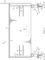
Figure 4 is a top plan view of the example tray. -
Figure 5 is a bottom plan view of the example tray. -
Figure 6 is a side view of the example tray. -
Figure 7 is a perspective view of one end of the example tray, the position of a bay door latch being shown in broken lines. -
Figure 8 is a bottom perspective view of one end of the example tray. -
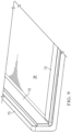
Figure 9 is a perspective view of an outer corner of the example tray, illustrating the position of magnetic strips. -
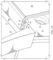
Figure 10 is a perspective view illustrating the attachment of a bag to the example tray. -
Figure 11 is a cross-sectional view illustrating attachment of a pad to the end of a standoff rod. -
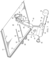
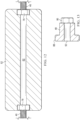
Figure 12 is a cross-sectional view of a standoff rod support. -
Figure 13 is a cross-sectional view of a knob used to adjust the position of the standoff rod. -
Figure 14 is a fragmentary side view of a portion of a vehicle bay showing a bay door latch. -
Figure 15 is a view similar toFigure 14 , but showing the example tray having been mounted on the side of the vehicle along the open bay. -
Figure 16 is a flow diagram of a method of installing an example tray along an open bay in the side of a vehicle. - Referring first to
Figure 1 , a structure such as a vehicle 20 (e.g. an aircraft, spacecraft, rotorcraft, unmanned aerial vehicle, wheeled or tracked vehicle, marine or submarine vehicle, and the like) typically may have one ormore bays 26 in a side of afuselage 22 that are normally covered by bay doors (not shown). Thebays 26 contain various systems or components that require periodic service and/or inspection by a technician. In order to aid the technician in performing the service/inspection, atray 30 is removably attached to theaircraft 20, along abottom edge 24 of anopen bay 26, between two lug-like bay door latches 28 (Figure 14 ). Thebay latches 28 secure the bay door against thefuselage 22 of theaircraft 20 in a closed, locked position. Thetray 30 includes ashelf 34 on which items such as tools, work instructions, new/replacement parts, laptop computers, etc., can be temporarily placed for ready access within arms' reach of the technician, thereby eliminating the need for placing these parts inside theopen bay 26 and reducing the potential for these items to become FOD within theopen bay 26. As will be discussed later in more detail, thetray 30 is removably mounted along and supported on a sill oredge 24 of theopen bay 26, allowing the technician ready access to any items placed on theshelf 34. As later described, thetray 30 includes numerous features that allow a technician to perform various services without bending or stepping away from theopen bay 26. - Referring also to
Figures 2-10 , thetray 30 broadly includes a flat or substantiallyflat shelf 34, and a pair of spaced aparthanger assemblies 36 that removably mount thetray 30 on the side of theaircraft 20 along theedge 24 of theopen bay 26. Theshelf 34 may be formed of any suitable, rigid material such as a metal, e.g. aluminum, plastic, or a reinforced composite material. While the exemplary shelf is rectangular in shape, other shelf shapes are possible without departing from the present solution. - The
shelf 34 includes an outer, up-standinglip 70 which assists in preventing FOD from falling off the front edge of theshelf 34. Optionally,magnetic strips 72 are adhesively attached to theshelf 34 along its sides and outer edges which function to prevent metallic FOD from sliding off the outer edges of theshelf 34. As discussed below in more detail, theshelf 34 includes two pairs of parallel, spaced apartslots 64 therein which allow the hanger assemblies 36 to be slid toward or away from each other to any of a plurality of adjustment positions best suited to support thetray 30 on theaircraft 20. Optionally, theshelf 34 may include one ormore openings 62 therein that function as handholds which allow thetray 30 to be gripped and transported by a technician. - Optionally, a container such as a
bag 60 may be attached to an outer edge of theshelf 34. Thebag 60 may be formed of any suitable material such as canvas and functions as a storage area for specialized tools, parts, expendables, etc. As best seen inFigures 3 and10 , thebag 60 includes anupper lip 60a that is fastened to theshelf 34 by a set ofreleasable fastener strips 74, such as Velcro® brand hook and loop fabric fastener strips, thereby allowing thebag 60 to be easily removed or replaced when desired. In other examples, the container may be an open top basket-like structure (not shown). - In some examples, including the illustrated example, two of the laterally spaced apart
hanger assemblies 36 are provided, however in other examples, depending on the length of theshelf 34, more than twohanger assemblies 36 may be desirable. Each of thehanger assemblies 36 broadly comprises anupper arm 38, alower arm 40, and a standoff 45 (Figure 3 ) on the bottom of abracket 42 that is attached to thelower arm 40. Theupper arm 38 extends upwardly above theshelf 34 and includes, at its upper end, a pair of spaced apartears 54, each having an aperture therein. A quick release, locking pin 56 (e.g., detent pin, ball lock, plunger pins, cotter pins, and the like) passes through the aperture in theears 54 and pivotally mounts thehanger assembly 36 on thebay door latch 28. As will be discussed later, pivotal mounting of thetray 30 on thelatches 28 facilitates leveling theshelf 34 during tray installation. In other examples, theupper arms 38 may include a variety of fixtures or mechanisms that adapt them to be releasably connected to the particular latch configuration used to latch the bay door. The quick release, locking pins 56 may be connected bylanyards 58 to theupper arms 38 in order to keep them readily accessible. In some examples, including the illustrated example, theupper arms 38 are inclined at a preselected angle (not shown) relative to the plane of theshelf 34, which will depend upon the particular application. - The
lower arms 40 are located beneath and are attached to the bottom surface of theshelf 34 byscrews 66 that pass throughslots 64 in theshelf 34. In this example, there are two sets ofslots 64, however in other examples, there may be as few as one or greater than two of theslots 64. Threaded knobs 68 on the end of thescrews 66 tighten thelower arms 40 against theshelf 34, thereby locking thehanger assemblies 36 in fixed positions along theslots 64. Loosening of the threadedknobs 68 releases thehanger assemblies 36, permitting them to slide toward or away from each other within theslots 64, thereby allowing adjustment of the lateral spacing between thehanger assemblies 36. - Each of the
standoffs 45 comprises a threadedstandoff rod 46 passing through astandoff support 52 that is suspended beneath theshelf 34 by abracket 42. Thebracket 42 may include one or more lightening holes 44 for weight reduction, and may be attached to the bottom of thelower arms 40 by fasteners (not shown), welding or other means of attachment. In some examples, thebracket 42 may be integrally formed with thelower arm 40 by 3D printing, or other additive manufacturing techniques. Thestandoff support 52 is cylindrical in shape and may be integrally formed with or attached to the bottom of thebracket 42. In some examples, including the illustrated example, thestandoff support 52 is hollow and includes end caps 76 provided withco-aligned insert nuts 78 in its opposite ends. Thestandoff rod 46 is threaded along its length and functions as a screw passing through the insert nuts 78. Thebracket 42 is configured to hold thestandoff rod 46 at a desired angle θ (Figure 6 ) relative to the plane of theshelf 34 in order to best orient thestandoff rod 46 for a particular application. - In other examples, shown in
Figure 12 , thestandoff support 52 may be a solid body formed of any suitable material and has alongitudinal passageway 82 therethrough for receiving thestandoff rod 46. In some examples, thebracket 42 and thestandoff support 52 are integrally formed of a rigid material as by casting or 3D printing. The outer end of thestandoff rod 46 is provided with apad 50 configured to engage thefuselage 22 or other structure on which thetray 30 is mounted. In some examples, shown inFigure 11 , thepad 50 is mounted on the end of thestandoff rod 46 by asocket 80 which may be pressed or insert molded into thepad 50. Thepad 50 may be formed of any suitable flexible or soft material such as elastomer that will not damage theouter skin 32 of thefuselage 22. The second end of thestandoff rod 46 is provided with around knob 48 having a knurledouter surface 88. Theknob 48 includes aninsert nut 86 aligned with acentral bore 90 that receives a threaded end of thestandoff rod 46. Turning of theknob 48 displaces thestandoff rod 46, thereby adjusting the position of thepad 50 relative to theside 96 of theaircraft 20. Because thestandoff rod 46 is displaceable along its length, thestandoffs 45 adapt thetray 30 for mounting on a wide range structures with various geometries. - Attention is now directed to
Figures 14 and 15 which illustrates how thetray 30 may be positioned in preparation for mounting it on theside 96 of a structure, such as beneath anopen bay 26 in thefuselage 22 of anaircraft 20. As seen inFigure 14 , theopen bay 26 typically has a bay door locking mechanism that includes structures such as alatch 28 along anedge 92 that is configured to be engaged by a mechanism on a bay door. Thelatch 28 includes anaperture 94. Thetray 30 is initially positioned along theside 96 of theaircraft 20, with theears 54 aligned with thelatch 28 such that thelatch 28 is inserted between theears 54, with the throughholes 54a in theears 54 aligned with theapertures 94 in thelatches 28. Next, the locking pins 56 are inserted through theears 54 in thelatches 28, thereby locking theupper arms 38 on theedge 92. Depending upon the configuration of theears 54, the locking pins 56 allow thetray 30 to pivot 98, permitting theshelf 34 to be pivoted to a level position by the installer. Next, the installer adjusts the length of thestandoff rods 46 so that thepads 50 engage theside 96 of thefuselage 22 to limit pivoting of theshelf 34, causing theshelf 34 to be held in a level position. - With the
tray 30 installed as described above, FOD can be placed on theshelf 34 within ready reach of a service technician, eliminating the need for placing items inside theopen bay 26 where they become FOD that may be lost or forgotten. The outer, up-standinglip 70 on theshelf 34 prevents larger items from falling off the front edge of theshelf 34, while themagnetic strips 72 prevent smaller metallic items from sliding or rolling off theshelf 34. The lateral adjustability on thehanger assemblies 36, combined with the adjustable length of thestandoff rods 46 allows thetray 30 to be mounted on any of a wide range of structures having various geometries and features. Thetray 30 may be easily removed from theaircraft 20 simply by removing the locking pins 56 and lifting thetray 30 away fromside 96 of theaircraft 20. - Attention is now directed to
Figure 16 which illustrates the overall steps of a method of installing atray 30 along anopen bay 26 in theside 96 of anaircraft 20. At 102 thetray 30 is positioned along theopen bay 26, and at 104 thetray 30 is mounted along anedge 92 of theopen bay 26. The positioning step performed at 102 includes positioning thetray 30 along anedge 92 of the open bay, and aligning theupper arms 38 with abay door latch 28 which may comprise inserting thelatch 28 between a pair ofears 54 on theupper arms 38. At 110, theupper arms 38 are attached to thebay latch 28 by inserting locking pins 56 between theupper arms 38 and thebay door latch 28. Then, at 112, thetray 30, and more particularly theshelf 34 are pivoted to a level position following which at 114,standoff rods 46 are adjusted in length so that they engage theside 96 of theaircraft 20 and support thetray 30 in a level position. - The description of the different illustrative examples has been presented for purposes of illustration and description, and is not intended to be exhaustive or limited to the examples in the form disclosed. Many modifications and variations will be apparent to those of ordinary skill in the art. Further, different illustrative examples may provide different advantages as compared to other illustrative examples. The example or examples selected are chosen and described in order to best explain the principles of the examples, the practical application, and to enable others of ordinary skill in the art to understand the disclosure for various examples with various modifications as are suited to the particular use contemplated.
- One or more features of the illustrative examples are described in the following clauses. These causes are examples of features not intended to limit other illustrative examples.
- Clause 1. A tray configured to be removably mounted on a side of a structure, comprising: a shelf; and a pair of hanger assemblies spaced apart from each other and configured to hang the shelf on the structure, each of the hanger assemblies including an upper arm removably attached to the structure, and a lower arm configured to support the shelf.
- Clause 2. A tray as in clause 1, wherein each of the upper arms is configured to pivotally mount the hanger assembly on the structure.
- Clause 3. A tray as in one of clauses 1 or 2, wherein each of the hanger assemblies further includes a standoff located beneath the shelf and configured to limit pivoting of the tray.
- Clause 4. A tray as in clause 3, wherein the standoff includes: a rod, and a pad on one end of the rod configured to engage the structure.
- Clause 5. A tray as in clause 4, wherein: each of the hanger assemblies includes a bracket below the shelf, and the rod is a screw mounted on the bracket and adjustable to each of a plurality of positions.
- Clause 6. A tray as in any of clauses 1 to 5, wherein each of the hanger assemblies includes a pin releasably connecting one of the upper arms with the structure.
- Clause 7. A tray as in clause 6, wherein each of the hanger assembly includes: a pair of ears configured to receive a portion of the structure therein, and wherein the pin passes through the structure and the ears.
- Clause 8. A tray as in any of clauses 1 to 7, wherein: the shelf includes slots therein, and the hanger assemblies are mounted on the shelf for sliding movement along the slots toward and away from each other.
- Clause 9. A tray as in any of clauses 1 to 8, wherein the shelf includes: at least one up-standing lip along an outer edge of the shelf, and a magnetic strip attached to the lip.
- Clause 10. A tray as in any of clauses 1 to 9, further comprising: a bag removably attached to the shelf along an outer edge of the shelf.
- Clause 11. A tray configured to be mounted along an open bay in a side of an aircraft, comprising: a shelf; and a pair of hanger assemblies configured to hang the shelf on the side of the aircraft beneath the open bay, each of the hanger assemblies including an upper arm configured to be attached to the aircraft along an edge of the open bay.
- Clause 12. A tray as in clause 11, further comprising: a lower arm connected to the upper arm and configured to support the shelf.
- Clause 13. A tray as in clause 11 or 12, further comprising: a standoff connected with and located beneath the shelf, the standoff being configured to engage the side of the aircraft.
- Clause 14. A tray as in clause 13, wherein the standoff includes a rod displaceable along its length to any of a plurality of adjustment positions.
- Clause 15. A tray as in clause 14, wherein: the rod is a screw, and the standoff further includes a pad on an end of the rod configured to engage the side of the aircraft.
- Clause 16. A tray as in any of clauses 11-15, wherein: the shelf includes slots therein, and the hanger assemblies are mounted in the slots for sliding movement toward and away from each other allowing adjustment of a spacing between the hanger assemblies.
- Clause 17. A method of installing a tray along an open bay in a side of an aircraft, comprising: positioning a tray along the open bay; and mounting the tray along an edge of the open bay.
- Clause 18. A method as in clause 17, wherein mounting the tray includes attaching the tray to a portion of a latch on the open bay.
- Clause 19. A method as in clause 18, wherein attaching the tray includes releasably connecting the tray to the latch, thereby allowing the tray to be removed from the side of the aircraft.
-
Clause 20. A method as in any of clauses 17-19, wherein mounting the tray along the edge includes installing standoffs between the tray and the side of the aircraft. - Clause 21. An aircraft comprising: an open bay in a side of the aircraft; a tray configured to be mounted along the open bay, the tray comprising: a shelf; and a pair of hanger assemblies configured to hang the shelf on the side of the aircraft beneath the open bay, each of the hanger assemblies including an upper arm configured to be attached to the aircraft along an edge of the open bay.
-
Clause 22. An aircraft as in clause 21, wherein the tray further comprises: a lower arm connected to the upper arm and configured to support the shelf. - Clause 23. An aircraft as in
clause 21 or 22, wherein the tray further comprises: a standoff connected with and located beneath the shelf, the standoff being configured to engage the side of the aircraft. -
Clause 24. An aircraft as in clause 23, wherein the standoff includes a rod displaceable along its length to any of a plurality of adjustment positions. - Clause 25. An aircraft as in
clause 24, wherein: the rod is a screw, and the standoff further includes a pad on an end of the rod configured to engage the side of the aircraft. -
Clause 26. An aircraft as in any of clauses 21-25, wherein: the shelf includes slots therein, and the hanger assemblies are mounted in the slots for sliding movement toward and away from each other allowing adjustment of a spacing between the hanger assemblies. - Clause 27. An aircraft comprising: an open bay in a side of the aircraft; a tray as in any of clauses 1 to 16.
-
Clause 28. A method of installing a tray as in any of clauses 1 to 16 along an open bay in a side of an aircraft, the method comprising: positioning the tray along the open bay; and mounting the tray along an edge of the open bay. - Clause 29. A method as in
clause 28, wherein mounting the tray includes attaching the tray to a portion of a latch on the open bay. -
Clause 30. method as in clause 29, wherein attaching the tray includes releasably connecting the tray to the latch, thereby allowing the tray to be removed from the side of the aircraft. - Clause 31. A method as in any of
clauses 28 to 30, wherein mounting the tray along the edge includes installing standoffs between the tray and the side of the aircraft.
Claims (15)
- A tray (30) configured to be removably mounted on a side (96) of a structure (20), comprising:a shelf (34); anda pair of hanger assemblies (36) spaced apart from each other and configured to hang the shelf (34) on the structure (20),each of the hanger assemblies (36) including an upper arm (38) removably attached to the structure (20), and a lower arm (40) configured to support the shelf (34).
- A tray (30) as in claim 1, wherein each of the upper arms (38) is configured to pivotally mount the hanger assembly (36) on the structure (20).
- A tray (30) as in claim 2, wherein each of the hanger assemblies (36) further includes a standoff (45) located beneath the shelf (34) and configured to limit pivoting (98) of the tray (30) .
- A tray (30) as in claim 3, wherein the standoff (45) includes:a rod (46), anda pad (50) on one end of the rod (46) configured to engage the structure (20).
- A tray (30) as in claim 4, wherein:each of the hanger assemblies (36) includes a bracket (42) below the shelf (34), andthe rod (46) is a screw mounted on the bracket (42) and adjustable to each of a plurality of positions.
- A tray (30) as in any of claims 1-5, wherein each of the hanger assemblies (36) includes a pin (56) releasably connecting one of the upper arms (38) with the structure (20).
- A tray (30) as in claim 6, wherein each of the hanger assemblies (36) includes:a pair of ears (54) configured to receive a portion of the structure (20) therein, andwherein the pin (56) passes through the structure (20) and the ears (54).
- A tray (30) as in any of claims 1-7, wherein:the shelf (34) includes slots (64) therein, andthe hanger assemblies (36) are mounted on the shelf (34) for sliding movement along the slots (64) toward and away from each other.
- A tray (30) as in any of claims 1-8, wherein the shelf (34) includes:at least one up-standing lip (70) along an outer edge (24) of the shelf (34), anda magnetic strip (72) attached to the lip (70).
- A tray (30) as in any of claims 1-9, further comprising:
a bag (60) removably attached to the shelf (34) along an outer edge (92) of the shelf (34). - An aircraft (20) comprising:an open bay (26) in a side (96) of the aircraft (20);a tray (30) as in any of claims 1-10, wherein:the tray (30) is mounted along the open bay (26); andthe pair of hanger assemblies (36) hang the shelf (34) on the side (96) of the aircraft (20) beneath the open bay (26), each of the hanger assemblies (36) including an upper arm (38) attached to the aircraft (20) along an edge (24) of the open bay (26).
- An aircraft (20) as in claim 11 when dependent upon claim 3, wherein:
the standoff (45) is connected with beneath the shelf (34), the standoff (45) being configured to engage the side (96) of the aircraft (20). - An aircraft (20) as in claim 12 when dependent upon claim 4, wherein:
the pad (50) is configured to engage the side (96) of the aircraft (20). - A method of installing a tray (30) along an open bay (26) in a side (96) of an aircraft (20), comprising:positioning a tray (30) along the open bay (26); andmounting the tray (30) along an edge (92) of the open bay (26) .
- A method as in claim 14, wherein:mounting the tray (30) includes attaching the tray (30) to a portion of a latch (28) on the open bay (26); and, optionally,attaching the tray (30) includes releasably connecting the tray (30) to the portion of the latch (28), thereby allowing the tray (30) to be removed from the side (96) of the aircraft (20), and/or mounting the tray (30) along the edge (92) includes installing standoffs (45) between the tray (30) and the side (96) of the aircraft (20).
Applications Claiming Priority (1)
| Application Number | Priority Date | Filing Date | Title |
|---|---|---|---|
| US18/172,106 US12128542B2 (en) | 2023-02-21 | 2023-02-21 | Portable tray and installation method |
Publications (1)
| Publication Number | Publication Date |
|---|---|
| EP4420836A1 true EP4420836A1 (en) | 2024-08-28 |
Family
ID=90014547
Family Applications (1)
| Application Number | Title | Priority Date | Filing Date |
|---|---|---|---|
| EP24158540.5A Pending EP4420836A1 (en) | 2023-02-21 | 2024-02-20 | Portable tray and installation method |
Country Status (4)
| Country | Link |
|---|---|
| US (1) | US12128542B2 (en) |
| EP (1) | EP4420836A1 (en) |
| JP (1) | JP2024128996A (en) |
| CN (1) | CN118529352A (en) |
Citations (7)
| Publication number | Priority date | Publication date | Assignee | Title |
|---|---|---|---|---|
| DE1927599U (en) * | 1965-10-05 | 1965-11-18 | Manfred Roser | MOUNTING DEVICE. |
| US6006906A (en) * | 1998-01-21 | 1999-12-28 | Winnard; Stanley D. | Magnetic tool holding and storage apparatus |
| US6189847B1 (en) * | 1999-01-25 | 2001-02-20 | John Hart | Apparatus for attaching a wide range of article supporting fixtures to a variety of support surfaces |
| WO2004014198A2 (en) * | 2002-08-09 | 2004-02-19 | Babu Enterprises, Llc | Portable tray and tray mounts. |
| DE202016105542U1 (en) * | 2016-10-05 | 2016-12-05 | We Can International Corp. | suspension structure |
| US20180319006A1 (en) * | 2017-05-02 | 2018-11-08 | Joshua Jenkins | Socket Head Storage and Portage Apparatus |
| GB2583693A (en) * | 2019-02-28 | 2020-11-11 | Jones Frank | A temporary storage device |
Family Cites Families (41)
| Publication number | Priority date | Publication date | Assignee | Title |
|---|---|---|---|---|
| US1282489A (en) * | 1916-02-08 | 1918-10-22 | Frank A Strodel | Drawing-board holder. |
| US1958266A (en) * | 1932-06-13 | 1934-05-08 | Red Boy Inc | Curb service tray |
| US2201598A (en) * | 1938-07-11 | 1940-05-21 | Agnes J Towler | Flatiron stand |
| US2267861A (en) * | 1940-12-14 | 1941-12-30 | Louise B Haley | Utility tray |
| US2593222A (en) * | 1948-04-20 | 1952-04-15 | Tracy Florence Franklin | Support for service trays |
| US2645537A (en) * | 1948-12-20 | 1953-07-14 | William J Brath | Detachable service tray for automobile doors |
| US2680523A (en) * | 1952-10-30 | 1954-06-08 | Gale N O Heeter | Tray attachment for vehicle seats |
| US2687336A (en) * | 1953-08-17 | 1954-08-24 | George I Smith | Folding table for automobile seats |
| US2784041A (en) * | 1955-08-11 | 1957-03-05 | Hood Louis La | Detachable service tray for automobile doors |
| US2844429A (en) * | 1956-12-05 | 1958-07-22 | Frey Ephriam | Lap tray with adjustable leg-engaging means |
| US2932544A (en) * | 1957-07-05 | 1960-04-12 | Frank A Lambert | Collapsible support device for vehicles |
| US2865432A (en) * | 1958-06-02 | 1958-12-23 | Anderson G Dearing | Chair arm table |
| US3164109A (en) * | 1963-01-14 | 1965-01-05 | A W Atkinson | Means for mounting a serving tray within a vehicle |
| US3194186A (en) * | 1964-01-22 | 1965-07-13 | Brown Russell | Drive-in food tray |
| US3266443A (en) * | 1964-03-23 | 1966-08-16 | John B Lee | Car-hop serving tray |
| US3289615A (en) * | 1965-06-21 | 1966-12-06 | Howard J Marschak | Device readily attachable to a shelf or the like for forming a shelf extension or tray |
| US4811875A (en) * | 1988-03-24 | 1989-03-14 | Disimone Robert P | Portable automotive bench |
| US5005491A (en) * | 1990-04-04 | 1991-04-09 | Waterman Kathryn R | Automotive tray apparatus |
| US5331904A (en) * | 1991-11-29 | 1994-07-26 | Robert P. DiSimone | Mechanic's tool trays and support assembly |
| US5302014A (en) * | 1992-10-19 | 1994-04-12 | Hobson George K | Cart for tying fishing lures |
| US5386915A (en) * | 1993-11-03 | 1995-02-07 | Sirhan; Eddie | Air tool rack |
| CA2136149A1 (en) * | 1993-11-18 | 1993-05-09 | Garry R. Sheldrick | Mechanic's work tray |
| US5590607A (en) * | 1994-09-01 | 1997-01-07 | Howard; Thomas E. | Portable shelf for notebook computers |
| US5598786A (en) * | 1995-01-18 | 1997-02-04 | Patterson; Lawrence W. | Laptop desk |
| US5755411A (en) * | 1995-11-29 | 1998-05-26 | Still Strong Corporation | Rifle mount for vehicle and method of utilizing same |
| US5722329A (en) * | 1997-01-13 | 1998-03-03 | Weng; Jung-Yi | Wall flower support structure |
| US5803422A (en) * | 1997-04-30 | 1998-09-08 | Buehler; Dieter | Tool and parts tray |
| US6293206B1 (en) * | 2001-01-16 | 2001-09-25 | Clayton N. Simon | Portable folding tray for vehicles |
| ITMI20010635U1 (en) * | 2001-12-05 | 2003-06-05 | Artsana Spa | SIMPLE AND SAFE POSITIONING TABLE SEAT |
| US6729439B1 (en) * | 2003-03-04 | 2004-05-04 | Antonios Zlatis | Tool support attachment for a ladder |
| US7354023B1 (en) * | 2005-03-07 | 2008-04-08 | Wappler Michael J | Tool and part holding tray |
| US8511240B1 (en) * | 2012-04-25 | 2013-08-20 | David Strock | Baby valet assembly |
| US8985335B1 (en) * | 2013-02-19 | 2015-03-24 | Stephen J. Fisher | Magnetically mountable tray device |
| US8857347B1 (en) * | 2013-09-19 | 2014-10-14 | Keysheen Industry (Shanghai) Co., Ltd. | Foldable hanging table |
| US9770101B2 (en) * | 2013-10-04 | 2017-09-26 | Tail Gater Tire Table, Inc. | Table tire |
| US8985033B1 (en) * | 2014-02-27 | 2015-03-24 | James Whitlock | Adjustable tattoo table |
| US9089203B1 (en) * | 2014-11-10 | 2015-07-28 | Sultan Qaboos University | Desk extension |
| US11147396B2 (en) * | 2018-08-08 | 2021-10-19 | Moët Hennessy USA, Inc. | Display shelf system |
| US10973321B2 (en) * | 2018-09-04 | 2021-04-13 | Steelcase Inc. | Workspace system and components and method for the use thereof |
| US11724631B1 (en) * | 2019-04-09 | 2023-08-15 | Randall E. Arnall | Foldable bracket assembly for supporting a grill or table |
| US10786073B1 (en) * | 2019-05-22 | 2020-09-29 | Anthony Dillard | Table attachable tray assembly |
-
2023
- 2023-02-21 US US18/172,106 patent/US12128542B2/en active Active
-
2024
- 2024-02-20 EP EP24158540.5A patent/EP4420836A1/en active Pending
- 2024-02-21 JP JP2024024202A patent/JP2024128996A/en active Pending
- 2024-02-21 CN CN202410192317.3A patent/CN118529352A/en active Pending
Patent Citations (7)
| Publication number | Priority date | Publication date | Assignee | Title |
|---|---|---|---|---|
| DE1927599U (en) * | 1965-10-05 | 1965-11-18 | Manfred Roser | MOUNTING DEVICE. |
| US6006906A (en) * | 1998-01-21 | 1999-12-28 | Winnard; Stanley D. | Magnetic tool holding and storage apparatus |
| US6189847B1 (en) * | 1999-01-25 | 2001-02-20 | John Hart | Apparatus for attaching a wide range of article supporting fixtures to a variety of support surfaces |
| WO2004014198A2 (en) * | 2002-08-09 | 2004-02-19 | Babu Enterprises, Llc | Portable tray and tray mounts. |
| DE202016105542U1 (en) * | 2016-10-05 | 2016-12-05 | We Can International Corp. | suspension structure |
| US20180319006A1 (en) * | 2017-05-02 | 2018-11-08 | Joshua Jenkins | Socket Head Storage and Portage Apparatus |
| GB2583693A (en) * | 2019-02-28 | 2020-11-11 | Jones Frank | A temporary storage device |
Also Published As
| Publication number | Publication date |
|---|---|
| CN118529352A (en) | 2024-08-23 |
| US12128542B2 (en) | 2024-10-29 |
| US20240278417A1 (en) | 2024-08-22 |
| JP2024128996A (en) | 2024-09-26 |
Similar Documents
| Publication | Publication Date | Title |
|---|---|---|
| KR102385583B1 (en) | Flight test equipment installation system and method | |
| US7448812B2 (en) | Camera mount | |
| US9611975B2 (en) | Equipment mounting system | |
| US9551499B1 (en) | Hinge assembly for supporting a fan on a roof | |
| US20030019824A1 (en) | Variable mount rack system arm assembly | |
| US20080213034A1 (en) | Swivel fitting attachment apparatus | |
| US20090178821A1 (en) | Modular Rack for Mounting Avionics Equipment | |
| US20040201335A1 (en) | Universal computer enclosure | |
| US12501574B2 (en) | Cabinet air dam enclosure | |
| US20190375338A1 (en) | Cargo Rack System for a Vehicle | |
| CA2659832A1 (en) | Frame element, storage bin and method for installing a storage bin in an aircraft | |
| US20240084962A1 (en) | Remote Release Assembly for a Surface Mount | |
| US20200297559A1 (en) | Medical stretcher transfer system | |
| US5497968A (en) | Emergency response equipment securing system and accessories | |
| US20160231081A1 (en) | Multi-positional holster accessory attachment system | |
| RU2563379C2 (en) | Fixing device for helicopter cargo basket and method to use it | |
| US12128542B2 (en) | Portable tray and installation method | |
| US20030000077A1 (en) | Assembling composite structures | |
| US20220315234A1 (en) | Guide systems for installing aircraft structures | |
| DE102017104754A1 (en) | Holding device for attaching a mobile oxygen or respirator, optionally with oxygen cylinder and / or oxygen or respirator | |
| US20130256479A1 (en) | Galley insert mounting system | |
| US20090115297A1 (en) | Device for installing and removing high insertion force modules | |
| US4341407A (en) | Adjustable retention latch assembly | |
| US10294720B2 (en) | Ergonomic ladder | |
| US11958540B2 (en) | Vehicle storage system |
Legal Events
| Date | Code | Title | Description |
|---|---|---|---|
| PUAI | Public reference made under article 153(3) epc to a published international application that has entered the european phase |
Free format text: ORIGINAL CODE: 0009012 |
|
| STAA | Information on the status of an ep patent application or granted ep patent |
Free format text: STATUS: THE APPLICATION HAS BEEN PUBLISHED |
|
| AK | Designated contracting states |
Kind code of ref document: A1 Designated state(s): AL AT BE BG CH CY CZ DE DK EE ES FI FR GB GR HR HU IE IS IT LI LT LU LV MC ME MK MT NL NO PL PT RO RS SE SI SK SM TR |
|
| STAA | Information on the status of an ep patent application or granted ep patent |
Free format text: STATUS: REQUEST FOR EXAMINATION WAS MADE |
|
| 17P | Request for examination filed |
Effective date: 20250114 |