EP4420612A1 - Computed tomography system and method for performing a computed tomography scan - Google Patents
Computed tomography system and method for performing a computed tomography scan Download PDFInfo
- Publication number
- EP4420612A1 EP4420612A1 EP23187885.1A EP23187885A EP4420612A1 EP 4420612 A1 EP4420612 A1 EP 4420612A1 EP 23187885 A EP23187885 A EP 23187885A EP 4420612 A1 EP4420612 A1 EP 4420612A1
- Authority
- EP
- European Patent Office
- Prior art keywords
- examination area
- ray
- ray source
- computed tomography
- source array
- Prior art date
- Legal status (The legal status is an assumption and is not a legal conclusion. Google has not performed a legal analysis and makes no representation as to the accuracy of the status listed.)
- Granted
Links
Images


Classifications
-
- A—HUMAN NECESSITIES
- A61—MEDICAL OR VETERINARY SCIENCE; HYGIENE
- A61B—DIAGNOSIS; SURGERY; IDENTIFICATION
- A61B6/00—Apparatus or devices for radiation diagnosis; Apparatus or devices for radiation diagnosis combined with radiation therapy equipment
- A61B6/02—Arrangements for diagnosis sequentially in different planes; Stereoscopic radiation diagnosis
- A61B6/03—Computed tomography [CT]
- A61B6/032—Transmission computed tomography [CT]
-
- A—HUMAN NECESSITIES
- A61—MEDICAL OR VETERINARY SCIENCE; HYGIENE
- A61B—DIAGNOSIS; SURGERY; IDENTIFICATION
- A61B6/00—Apparatus or devices for radiation diagnosis; Apparatus or devices for radiation diagnosis combined with radiation therapy equipment
- A61B6/40—Arrangements for generating radiation specially adapted for radiation diagnosis
- A61B6/4007—Arrangements for generating radiation specially adapted for radiation diagnosis characterised by using a plurality of source units
-
- A—HUMAN NECESSITIES
- A61—MEDICAL OR VETERINARY SCIENCE; HYGIENE
- A61B—DIAGNOSIS; SURGERY; IDENTIFICATION
- A61B6/00—Apparatus or devices for radiation diagnosis; Apparatus or devices for radiation diagnosis combined with radiation therapy equipment
- A61B6/40—Arrangements for generating radiation specially adapted for radiation diagnosis
- A61B6/4007—Arrangements for generating radiation specially adapted for radiation diagnosis characterised by using a plurality of source units
- A61B6/4014—Arrangements for generating radiation specially adapted for radiation diagnosis characterised by using a plurality of source units arranged in multiple source-detector units
-
- A—HUMAN NECESSITIES
- A61—MEDICAL OR VETERINARY SCIENCE; HYGIENE
- A61B—DIAGNOSIS; SURGERY; IDENTIFICATION
- A61B6/00—Apparatus or devices for radiation diagnosis; Apparatus or devices for radiation diagnosis combined with radiation therapy equipment
- A61B6/42—Arrangements for detecting radiation specially adapted for radiation diagnosis
- A61B6/4275—Arrangements for detecting radiation specially adapted for radiation diagnosis using a detector unit almost surrounding the patient, e.g. more than 180°
Definitions
- the invention relates to a computed tomography system, a method for performing a computed tomography scan and a computer program.
- CT computed tomography
- x-ray attenuation signals along x-rays with different directions are combined to reconstruct images of an examined object of interest.
- the time it takes to acquire data of one CT measurement from the different directions may be referred to as acquisition time.
- the examined object is moving during acquisition.
- moving organs such as the heart, or a patient slightly moving parts of his/her body, e.g., the limbs or the chest due to breathing, may potentially lead to motion artifacts. Therefore, it is desirable to keep the acquisition time as short as possible.
- On of the main factors that may limit the acquisition speed is an x-ray tube power. In order to achieve a good signal-to-noise ratio, a sufficient amount of signal is required.
- the accumulated photon energy that reaches the CT detectors from the x-ray tube determines the accumulated signal. Accordingly, for a desired signal-to-noise ratio, the possible acquisition speed is typically proportional to the x-ray tube power. Thus, for a higher acquisition speed, a higher tube power is required.
- increasing the x-ray tube power is typically associated with increased costs and space requirements.
- the power of individual x-ray sources tends to be rather low. For example, the maximum power may be at around 10kW, which is significantly lower than what may be used with rotating systems. Further increasing the power may in many situations be technically difficulty or not feasible at all.
- a computed tomography (CT) system comprises an examination area, a static x-ray source array with x-ray sources that are arranged around the examination area, a detector arrangement with detectors that are arranged around the examination area, and a beam collimator, preferably a circular beam collimator, positioned in a radial direction between the x-ray source array and the examination area.
- CT computed tomography
- the computed tomography system is configured to acquire computed tomography scan data of an object or subject placed in the examination area by simultaneously activating at least two x-ray sources and measuring the corresponding signals with the detector arrangement and repeating the simultaneous activation multiple times with different x-ray sources of the x-ray source array, respectively, in order to acquire a full scan of the object or subject.
- a computed tomography system having a static x-ray source array may be called a static computed tomography system.
- the term "static computed tomography system” may refer to a computed tomography system with a static x-ray source array.
- the static computed tomography system may preferably be a computed tomography system of the fourth generation.
- a static x-ray source array may be an x-ray source array, wherein the x-ray sources are stationary during operation. In other words, the x-ray sources are not rotated around the examination area.
- a scan of the examination area may be achieved by selectively activating x-ray sources.
- the x-ray sources may be selectively activated by electronic switching.
- a collimator limiting the x-ray beam distribution in a direction perpendicular to an axial direction may be typically thought not to be feasible because the collimator used for one x-ray source might block other x-ray sources of the x-ray source array.
- a beam collimator can still be enough to separate or at least distinguish the signals sufficiently even for a static x-ray source array.
- separating the signals may be feasible with the beam collimator even if the collimator comprises an essentially constant opening in a direction perpendicular to the axial direction. This is explained in more detail in later parts of this description.
- the total power of the x-ray sources per time unit can be increased.
- activating two x-ray sources at once can increase the power by the factor 2.
- This can be particularly advantageous for static CT, since, according to the current state of the art, it is often difficult or even impossible to provide the individual x-ray sources with a power output comparable to the x-ray power output of a rotating CT system.
- a maximum power of x-ray sources for static x-ray source arrays may be in the range of about 10 kW.
- rotating CT systems typically much higher power values are possible.
- activating two x-ray sources simultaneously may decrease the overall scan time that is needed.
- the computed tomography system may enable a better usage of the available power reserve, by providing more x-ray power per time unit, and an improved temporal resolution with the static x-ray source array.
- the system is configured to repeat the simultaneous activation multiple times with different x-ray sources of the x-ray source array, respectively. For example, two opposite positioned x-ray sources may be activated simultaneously, and then two other opposite positioned x-ray sources may be activated and so on, until all the x-ray sources are activated and/or until enough data is acquired to reconstruct an image.
- an axial direction is a direction that is perpendicular to the area that is surrounded by the x-ray sources.
- the axial direction may also be described herein as z-direction.
- a radial direction is a direction that is perpendicular to the axial direction.
- the radial direction may be any direction from or to the centre of the examination area that is perpendicular to the axial direction.
- the radial direction may also be described as x,y-direction or as any direction on the x,y-plane from or to the centre of the examination area.
- the examination area is preferably designed such that an object or subject can be placed in the examination area.
- a subject may, for example, be a human being or animal, such as a patient.
- An object may, for example, be part of a subject, such as a limb or an organ.
- the examination area may correspond to a scan field of view.
- a scan field of view may be an area, every section of which can be reached by at least some of the x-ray beams from all x-ray sources such that the x-ray beams, potentially attenuated by the object or subject, reach at least one of the detectors after going through the examination area.
- the x-ray beams can reach the detectors in a straight line through the examination area.
- the x-ray sources of the x-ray source array are arranged around the examination area.
- the x-ray sources may be distributed according to any shape around the examination area.
- the shape is such that all beam angles required for an CT image reconstruction are covered.
- the x-ray sources may be distributed at least approximately on a circle.
- a circular distribution may be advantageous for making a reconstruction more efficient and/or easier.
- the circle may have the form R f cos ⁇ , R f sin ⁇ , 0
- the orientation of R f is parallel to the orientation or the radial direction(s) and perpendicular to the axial direction.
- the centre of the circle corresponds to the centre of the examination area.
- the x-ray source array may comprise a number of x-ray sources in the order of magnitude of a few hundred or several hundred. For example, more than 100 x-ray sources may be provided.
- the x-ray sources may be any kind of x-ray sources suitable for CT.
- the x-ray sources may be x-ray tubes and/or field emitter-based x-ray sources.
- X-ray tubes may, for example, be heat-based x-ray tubes or field emitter-based x-ray tubes.
- the detectors may be distributed according to any shape around the examination area.
- the shape is such that all beam angles required for an CT image reconstruction are covered.
- the detectors may be distributed at least approximately on a circle and/or on a cylinder around the examination area.
- a cylinder may mean that the detectors are not only distributed in a circle but are also distributed in an axial direction. This may be advantageous to allow detecting beams that are not only in a plane.
- the cylindrical axis goes through the centre of the examination area.
- the cylindrical axis is parallel to an axial direction.
- the cylinder may have the form R d cos ⁇ , R d sin ⁇ , z
- R d is the radius of the cylinder and z ranging between z dl ,z dh . Determines the height and the position of the cylinder in the axial direction.
- the orientation of R d is parallel to the orientation or the radial direction(s) and perpendicular to the axial direction.
- the detector arrangement may preferably be a static detector arrangement.
- a static detector arrangement may be designed such that it does not rotate around the examination area during a CT scan.
- the beam collimator is positioned in the radial direction between the x-ray source array and the examination area.
- the beam collimator may be adapted to the shape of the distribution of the x-ray sources.
- the beam collimator may be a circular beam collimator.
- the circle shape of the circular beam collimator may correspond to a circular arrangement of the x-ray sources.
- the collimator may comprise an opening essentially going around the examination area.
- the opening may be designed to correspond to the circular shape of the beam collimator and/or the circular distribution of the x-ray sources.
- the beam collimator may be designed to limit an extend of x-ray beams along the axial direction.
- the beam collimator may comprise two parts that are offset with respect to each other in the axial direction.
- the two parts may preferably be two circular parts.
- the two circular parts may preferably have an essentially identical radius with respect to each other.
- the two circular parts may be described by the equation R c cos ⁇ , R c sin ⁇ , z
- ⁇ ⁇ 0,2 ⁇ , z z cl z ch .
- ⁇ z cl , z ch ⁇ may define an upper and lower end in the axial direction of the opening of the beam collimator.
- the beam collimator is a static beam collimator.
- a static beam collimator may be designed such that it does not rotate around the examination area during a CT scan.
- the opening of the beam collimator may be adaptable.
- the system may be configured to adapt the opening based on the size and/or form of the object or subject.
- the system may be configured to adapt the size of the opening.
- the system may be configured to adapt the size of the opening at least in the axial direction. For example, a small object or subject may only require a smaller scan field of view corresponding to a smaller examination area. Hence, the system may be configured to reduce the size of the opening in the axial direction for a small object or subject. This may allow to regulate that beams from individual x-ray sources are more restricted, leading to less signal overlap.
- the detector arrangement and the x-ray source array are offset with respect to each other in an axial direction perpendicular to the radial direction, wherein an opening of the beam collimator is offset with respect to both, the x-ray source array and the detector arrangement, such that it is positioned between the x-ray source array and the detector arrangement in the axial direction.
- having an offset between the detectors and the x-ray source may be useful to ensure that backside of the detectors is not blocking the way of the x-ray beams that are aimed at the examination area. While it may generally be feasible under some circumstance, to have the x-ray sources and the detectors at the same axial position, e.g.
- an offset of the beam collimator may be advantageous in allowing to block off at least some of the beams in the x,y-plane due to the resulting geometry between x-ray source examination area and detectors. Hence, the offset may allow for fewer beams of different x-ray sources to reach the same detector. Accordingly, a separation between beams from simultaneously activated x-ray sources may be easier to achieve.
- the beam collimator is closer to the detector arrangement than to the x-ray source array.
- the beam collimator is offset with respect to the detector arrangement in the radial direction such that, in the radial direction, the beam collimator is positioned closer to the examination area than the detector arrangement.
- This particular variation, in combination with the offset in the axial direction, may be advantageous in enabling a further improved separation of two beams of simultaneously activated x-ray sources.
- an offset between the detector arrangement and the beam collimator is smaller than an offset between the x-ray source array and the detector arrangement.
- the x-ray source array, the x-ray sources that are to be activated simultaneously, and the beam collimator are arranged such that, during a scan, none of the detectors simultaneously receives beams from two different x-ray sources that both go through the examination area.
- beam collimation in the x,y-plane is only possible to a limited extend, e.g. indirectly via an offset of the beam collimator in the axial direction. This may lead to a large illuminated detector channel range. However, the range of the illuminated detector channel that is illuminated by beams going through the examination area may be smaller.
- an image reconstruction can still work rather well, as long as a projection of the examination area by beams from one x-ray source does not cover the projection of the examination area by beams from another x-ray source that is activated simultaneously.
- the detectors that are used to reconstruct data from beams of one x-ray source i.e. beams that go through the examination area
- the object or subject is restricted to be inside the examination area, only non-attenuated beams from the other x-ray source are received simultaneously.
- a method for performing a computed tomography scan with a static computed tomography system comprises an examination area, an x-ray source array with x-ray sources that are arranged around the examination area, a detector arrangement with detectors that are arranged around the examination area, and a beam collimator, in particular a circular beam collimator, positioned in a radial direction between the x-ray source array and the examination area.
- the computed tomography system may in particular be the computed tomography system as described herein, e.g. according to any embodiment of the computed tomography system as described herein.
- the method comprises the following steps:
- any embodiment of the computed tomography system as described herein may be configured to carry out the method according to any embodiments as described herein.
- step (b) For performing step (b) neither the x-ray source array, nor the detector arrangement nor the beam collimator are rotated around the examination area.
- step (b) may be repeated such that step (a) is repeated with at least two x-ray sources that are next to the previous at least two x-ray sources, respectively.
- another scheme of repetition is also conceivable.
- more than two x-ray sources are activated simultaneously, wherein the x-ray sources are activated such that the simultaneously activated x-ray sources are spaced equally on the x-ray source array around the examination area.
- spaced equally may mean that the smallest distance from one activated x-ray source to the nearest simultaneously activated x-ray source is the same across all simultaneously activated x-ray sources.
- the x-ray sources may be 360°/ N apart.
- the simultaneously activated x-ray sources are spaced equally, a particularly good distinction between the signals can be achieved.
- the x-ray sources may be activated such, that the spacing between the activated x-ray sources is always essentially the same across all repetitions of step (b).
- the number N may be chosen according to the size of the examination area or a corresponding scan field of view. In particular the number N may be greater for a smaller size of the examination area and smaller for a greater size of the examination area.
- the size of the examination area may be defined by the maximum distance of an outer surface of the object or subject in the examination area to the centre of the x-ray source array and/or of the examination area.
- the size of the examination area may be adapted dynamically based on the size of the object or subject. For example, when examining a small object, the size of the examination area may be set to be smaller and, when examining large object, the size of the examination area may be set to be greater than for the small object.
- exactly two x-ray sources are activated simultaneously.
- Two x-ray sources may allow a relatively large spacing, compared to more x-ray source, thus making it easier to distinguish between beams from the simultaneously activated x-ray sources.
- two x-ray sources may still allow for a significantly increased power output per time unit, e.g. twice the power output compared to only a single x-ray source activated at once.
- the two x-ray sources may be 180° ⁇ ⁇ , where ⁇ is an angle defining a deviation from 180°.
- the angle ⁇ activated may be set depending on the system geometry.
- the system geometry may comprise the examination area and the size of the examination area.
- the system geometry may comprise size, form and position of the x-ray source array, the detector arrangement and/or the beam collimator.
- an angle between the two simultaneously activated x-ray sources on the x-ray source array is essentially 180°.
- An angle of essentially 180° can be advantageous because, typically, the best separation between the two simultaneous beams may be achievable with this angle.
- a smallest angle between the two simultaneously activated x-ray sources on the x-ray source array is smaller than 180°, preferably smaller than 176°, more preferably between 175° and 90°.
- a smallest angle may be understood such that it describes the smallest distance between the two x-ray sources, following along around the x-ray source array. Deviating from a setting where the x-ray sources are 180° apart can be advantageous in allowing to have a better time resolution.
- the x-ray sources are exactly opposite the signal that can be acquired simultaneously by both x-ray sources is very similar. In particular, the corresponding x-ray beams going through the examination area are just taking the essentially opposite path.
- the x-ray sources are not exactly opposite each other, different directions may be measured simultaneously, thus allowing for a better correction of motion.
- the smallest angle between the two x-ray sources being 90° may be particularly advantageous. With an angle of 90° the movement correction may be particularly efficient.
- a separation of only 90° may be too close such that the separation of the signals may be difficult or even impossible.
- x-ray sources are activated simultaneously such that none of the detectors simultaneously receive beams from two different x-ray sources that both go through the examination area.
- each detector at most receives signals from one x-ray source that goes through the examination area.
- signals that do not go through the examination area may still be received. Not going through the examination are may be understood such, that the signals are not attenuated by the object or subject. Assuming that only air or, optionally, a constant material that is independent of the object or subject, is present in the area outside the examination area that is relevant for the path of the beams received by the detectors the beams outside the examination area will be not attenuated or attenuated with a constant number.
- the data measured by the respective detector may be a sum of data corresponding to a projection through the examination area from one x-ray source and unattenuated (or constant) data from other simultaneously activated x-ray sources.
- This superposition of x-rays may be relatively easy to correct when reconstructing the CT image.
- the method comprises a further step of acquiring data with the object or subject not being in the examination area to acquire unattenuated data, and another further step of using the unattenuated data to adjust the data acquired with the object or subject being in the examination area.
- the unattenuated data may be used to determine calculate which influence the x-rays not going through the examination area may have on the total received signal.
- the acquisition of the unattenuated data may be used as a calibration step.
- the unattenuated data may be acquired once and used for multiple scans of objects or subjects.
- the unattenuated data is acquired for each x-ray source individually.
- Acquiring the unattenuated data for each x-ray source individually may in particular mean acquiring the unattenuated data for each x-ray source separately.
- the unattenuated data may be acquired for one x-ray source after the other. Therefore, the interference between the x-ray sources may be reduced when acquiring the data. Accordingly, a particularly reliable allocation of received signals to individual x-ray sources may be possible.
- the adjusting is performed for each detector by subtracting the unattenuated data that does not cross the examination area before being detected by the detector from the data acquired with the object or subject being in the examination area.
- the data from one or more other x-ray sources can be subtracted from the received signal.
- the part of the data that originates from beams from other x-ray sources that are active at the same time as the "main x-ray source” can be subtracted essentially leaving only data from the main x-ray source. This subtraction can be possible due to the signals form the other x-ray sources being essentially unchanged by the object or subject because their respective beams are not going through the examination area before entering said specific detector.
- a filtered backprojection algorithm such as the one explained by Feldkamp, I., Davis, L. & Kress, in J. Practical cone-beam algorithm Journal of the Optical Society of America A: Optics and Image Science, and Vision, 1984, 1, 612-619 , may be used.
- This algorithm can preferably be applied when the object or subject is completely within the examination area.
- a noise reduction algorithm may be applied.
- the noise reduction may comprise a low pass filtering.
- Noise reduction may be advantageous for alleviating noise originating from unwanted signal contributions.
- Unwanted signal contributions may be the contributions from the other x-ray sources that do not pass the examination area, e.g. as described above. Due to these signals being unattenuated, their noise level may still be relatively high compared to the actual signal, in particular when the examined object or subject is large and/or causes a strong attenuation. Since noise is typically a random effect, the noise cannot always be eliminated by subtracting the acquired unattenuated data. Accordingly, the noise remaining after the subtraction may still be significant.
- the noise reduction may help to further improve the reconstructed image by removing and/or reducing the noise.
- an image reconstruction may be possible by an iterative approach.
- Kunze, H., Härer, H., Stierstorfer K. in Iterative extended field of view reconstruction, Proceedings of SPIE - The International Society for Optical Engineering, 2007 , may be adapted to be applied.
- a computer program comprising instructions which, when the program is executed by a control unit of a computed tomography system, cause the computed tomography system to carry out the method as described herein.
- the computed tomography system may preferably be a system as described herein. All features and advantages of the system and of the method may be adapted to the computer program and vice versa.
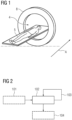
- Figure 1 shows a computed tomography system according to an embodiment of the invention.
- the computed tomography system comprises an examination area 4.
- the computed tomography system further comprises a static x-ray source array 1 with x-ray sources 11 that are arranged around the examination area 4, a detector arrangement 2 with detectors 21 that are arranged around the examination area 4, and a circular beam collimator 3 that is positioned in a radial direction between the x-ray source array 1 and the examination area 4.
- the array 1, the detector arrangement 2 and the beam collimator 3 are part of a CT ring 8.
- a subject 5, such as a patient, or part of a subject 5, i.e. an object may be positioned inside the examination area 4, e.g.
- the computed tomography system is configured to acquire computed tomography scan data according to an embodiment of a method as described herein. An example of a corresponding method is shown in Figure 2 .
- Figure 2 shows a flow diagram of a method for performing a computed tomography scan with a static computed tomography system according to an embodiment of the invention.
- the computed tomography system may, for example, be a system as shown in figure 1 .
- a first step 102 at least two x-ray sources 11 are activated simultaneously and the corresponding signals are measured with the detector arrangement 2 in order to acquire computed tomography scan data of the subject 5 or part of the subject 5 that is placed in the examination area 4.
- the first step 102 is repeated multiple times with different x-ray sources 11 of the x-ray source array 1, respectively, in order to acquire a full scan of the subject 5.
- the method may comprise a further step 101 of acquiring data with the object or subject 5 not being in the examination area 4 to acquire unattenuated data.
- the unattenuated data may be acquired for each x-ray source 11 of the x-ray source array 1 individually, in particular by acquiring the unattenuated data for each x-ray source 11 separately, i.e. one after the other.
- This further step 101 may preferably be performed before the other steps.
- steps 102 and 103 may also be performed before this step 101.
- this step 101 may be performed once and then be used for multiple performances of the method, i.e. for multiple applications of the computed tomography system.
- a further step 104 is provided, wherein the unattenuated data is to adjust the data acquired with the object or subject 5 being in the examination area 4.
- the adjusting may be performed for each detector 21 by subtracting the unattenuated data that does not cross the examination area 4 before being detected by the detector 21 from the data acquired with the object or subject 5 being in the examination area 4.
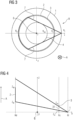
- Figure 3 shows a schematic representation of an axial view of the CT ring 8 according to an embodiment of the invention.
- the plane of view corresponds to the x and y directions.
- Figure 4 sows a schematic representation of a side view of the CT ring 8 according to the same embodiment of the invention.
- the z direction corresponds to the axial direction A.
- a static x-ray source array 1 with x-ray sources 11, a detector arrangement 2 with detectors 21, and a beam collimator 3 are arranged around the examination area 4.
- the x-ray source array 1, the beam detector arrangement 2, the beam collimator 3, and the examination area 4 are all arranged circularly around a common centre 6.
- the circular beam collimator 3 is positioned in a radial direction between the x-ray source array 1 and the examination area 4.
- the circular beam collimator 3 is also positioned in a radial direction between the detector arrangement 2 and the examination area 4.
- the radial direction is any direction propagating perpendicular to the axial direction A, i.e. in the x,y-plane, from or to the centre 6.
- the radial positions of the static x-ray source array 1, the detector arrangement 2, the beam collimator 3, and the examination area 4 are designated by R f , R d , R c , R fov , respectively.
- the x-ray sources 11 of the x-ray source array 1 are distributed on a circle defined by R f cos ⁇ , R f sin ⁇ , 0
- the detectors 21 of the detector arrangement 2 are distributed on a cylinder defined by R d cos ⁇ , R d sin ⁇ , z
- the beam collimator 3 can be defined by the upper (z ch ) and lower end of an opening 31 of the beam collimator 3 (z cl ).
- the examination area 4 can be defined by a circle R fov cos ⁇ , R fov sin ⁇ , 0
- the detector arrangement 2 is offset with respect to the x-ray source array 1 in the radial direction such that, in the radial direction, the detector arrangement 2 is positioned closer to the examination area 4 than the x-ray source array 1.
- R d is smaller than R f , in this embodiment.
- the examination area 4 corresponds to a scan field of view.
- the scan field of view is defined such that the detectors 21 of the detector arrangement 2 are fully illuminated for this scan field of view across the axial direction A.
- the scan field of view can be defined by outer beams 7 from the corresponding x-ray sources 11 of the x-ray source array 1.
- the detector arrangement 2 and the x-ray source array 1 are offset with respect to each other in the axial direction A.
- the opening 31 of the beam collimator 3 is offset with respect to both, the x-ray source array 1 and the detector arrangement 2, such that it is positioned between the x-ray source array 1 and the detector arrangement 2 in the axial direction A.
- FIG. 5 shows a schematic representation of an axial view of the CT ring 8 according to an embodiment of the invention.
- This embodiment may be the same as the one shown in figures 3 and 4 .
- two x-ray sources 11 are activated simultaneously.
- the two x-ray sources 11 are separated by 180° on the x-ray source array 1, i.e., in this example, one is positioned at 0° and one is positioned at 180°.
- none of the detectors 21 simultaneously receives beams from both x-ray sources 11 that both go through the examination area 4 (indicated by dashed and full lines). However, there may be some overlap with beams 71 that do not cross the examination area 4 (indicated by dotted lines).
- Figure 6 shows a schematic representation of an axial view of the CT ring 8 according to the embodiment shown in figure 5 while also illustrating some geometrical relations.
- equations for a projection of the beam collimator 3 on the cylindrical detector arrangement 2 can be derived.
- the projected z-coordinates may be plotted das a function of ⁇ , i.e., the angle of the detector 21 position.
- FIG. 7 A corresponding plot is shown in figure 7 .
- Figure 7 illustrates an example of the illumination of a detector 21 by two simultaneously activated x-ray sources 11 that are separated by 180°, i.e. that are, in this example, positioned at 0° and 180°.
- the opening 31 of the beam collimator 3 (defined by z cl , z ch ) is configured such that it fully illuminates the detector 21 (defined by z dl ,z dh ) for the whole scan field of view (defined by R fov ) corresponding to the examination area 4.
- the detector is fully illuminated within the projection of the scan field of view and partially illuminated between the projection of the scan field of view and the area defined by the dotted lines.
- the dotted lines correspond to the dotted lines as shown in figure 5 , designating beams 71 not crossing the scan field of view.
- the partial illumination rage from the x-ray source 11 at 0° does not cover any part of the scan field of view projection for the x-ray source 11 at 180°, and vice versa.
- Figure 8 shows a plot similar to the one of figure 7 but for three simultaneously activated x-ray sources 11.
- the x-ray sources 11 are activated such that the simultaneously activated x-ray sources 11 are spaced equally on the x-ray source array 1 around the examination area 4.
- the spacing between the x-ray sources 11 is 120°.
- the illumination of one of the x-ray sources 11 extends into part the detector corresponding to another one of the x-ray sources 11 (i.e., these are unwanted contributions).
- theses unwanted contributions are not crossing the scan field of view, i.e. they are not crossing the examination area 4, and are thus unattenuated.
- these unattenuated unwanted contributions can be measured in advance and subsequently be subtracted from the measurement. Accordingly, the actual measurement from within the examination area 4 may thus be improved.
- the opening 31 of the beam collimator 3 may be adapted to achieve a smaller scan field of view.
- R fov 150 mm
- z cl 3.2 mm
- z ch 5.8 mm
Landscapes
- Health & Medical Sciences (AREA)
- Life Sciences & Earth Sciences (AREA)
- Engineering & Computer Science (AREA)
- Medical Informatics (AREA)
- Radiology & Medical Imaging (AREA)
- Molecular Biology (AREA)
- Biophysics (AREA)
- Nuclear Medicine, Radiotherapy & Molecular Imaging (AREA)
- Optics & Photonics (AREA)
- Pathology (AREA)
- Physics & Mathematics (AREA)
- Biomedical Technology (AREA)
- Heart & Thoracic Surgery (AREA)
- High Energy & Nuclear Physics (AREA)
- Surgery (AREA)
- Animal Behavior & Ethology (AREA)
- General Health & Medical Sciences (AREA)
- Public Health (AREA)
- Veterinary Medicine (AREA)
- Pulmonology (AREA)
- Theoretical Computer Science (AREA)
- Apparatus For Radiation Diagnosis (AREA)
Abstract
Description
- The invention relates to a computed tomography system, a method for performing a computed tomography scan and a computer program.
- Independent of the grammatical term usage, individuals with male, female or other gender identities are included within the term.
- In computed tomography (CT) measurements, x-ray attenuation signals along x-rays with different directions are combined to reconstruct images of an examined object of interest. The time it takes to acquire data of one CT measurement from the different directions may be referred to as acquisition time. In many cases, the examined object is moving during acquisition. For example, moving organs, such as the heart, or a patient slightly moving parts of his/her body, e.g., the limbs or the chest due to breathing, may potentially lead to motion artifacts. Therefore, it is desirable to keep the acquisition time as short as possible. On of the main factors that may limit the acquisition speed is an x-ray tube power. In order to achieve a good signal-to-noise ratio, a sufficient amount of signal is required. The accumulated photon energy that reaches the CT detectors from the x-ray tube determines the accumulated signal. Accordingly, for a desired signal-to-noise ratio, the possible acquisition speed is typically proportional to the x-ray tube power. Thus, for a higher acquisition speed, a higher tube power is required. However, increasing the x-ray tube power is typically associated with increased costs and space requirements. In particular for static computed tomography systems with non-rotating x-ray sources and detectors, the power of individual x-ray sources tends to be rather low. For example, the maximum power may be at around 10kW, which is significantly lower than what may be used with rotating systems. Further increasing the power may in many situations be technically difficulty or not feasible at all.
- It is therefore an object of the invention to provide a computed tomography system and method to improve on the above-mentioned problems. For example, it would be desirable to provide a means to increase the power output per time unit and/or to improve a temporal resolution of a CT system with static x-ray sources.
- This object is met or exceeded by a computed tomography system according to claim 1, a method according to
claim 5, and a computer program according to claim 15. Further advantages and features result from the dependent claims, the description and the attached figures. - According to a first aspect of the invention, a computed tomography (CT) system is provided. The computed tomography system comprises an examination area, a static x-ray source array with x-ray sources that are arranged around the examination area, a detector arrangement with detectors that are arranged around the examination area, and a beam collimator, preferably a circular beam collimator, positioned in a radial direction between the x-ray source array and the examination area. The computed tomography system is configured to acquire computed tomography scan data of an object or subject placed in the examination area by simultaneously activating at least two x-ray sources and measuring the corresponding signals with the detector arrangement and repeating the simultaneous activation multiple times with different x-ray sources of the x-ray source array, respectively, in order to acquire a full scan of the object or subject.
- A computed tomography system having a static x-ray source array may be called a static computed tomography system. Hence, herein, the term "static computed tomography system" may refer to a computed tomography system with a static x-ray source array. The static computed tomography system may preferably be a computed tomography system of the fourth generation. A static x-ray source array may be an x-ray source array, wherein the x-ray sources are stationary during operation. In other words, the x-ray sources are not rotated around the examination area. A scan of the examination area may be achieved by selectively activating x-ray sources. For example, the x-ray sources may be selectively activated by electronic switching.
- To the knowledge of the inventors of this invention, at least with static x-ray sources, activating two or more sources at once has not been considered as a realistic option in the state of the art. This may be due to activating two or more sources at once can seem disadvantageous and even infeasible, since the signals from two (or more) x-ray sources may interfere with each other, e.g., x-rays from both (or more) x-ray sources may reach the same detector at the same time. In a rotating CT it may be easier to avoid this via collimation with a collimator that moves with the rotating x-ray source. On the other hand, for static CT, a collimator limiting the x-ray beam distribution in a direction perpendicular to an axial direction may be typically thought not to be feasible because the collimator used for one x-ray source might block other x-ray sources of the x-ray source array. However, it has been found that, surprisingly, a beam collimator can still be enough to separate or at least distinguish the signals sufficiently even for a static x-ray source array. In particular, separating the signals may be feasible with the beam collimator even if the collimator comprises an essentially constant opening in a direction perpendicular to the axial direction. This is explained in more detail in later parts of this description.
- By activating two or more x-ray sources simultaneously, the total power of the x-ray sources per time unit can be increased. For example, activating two x-ray sources at once can increase the power by the
factor 2. This can be particularly advantageous for static CT, since, according to the current state of the art, it is often difficult or even impossible to provide the individual x-ray sources with a power output comparable to the x-ray power output of a rotating CT system. For example, a maximum power of x-ray sources for static x-ray source arrays may be in the range of about 10 kW. With rotating CT systems, typically much higher power values are possible. Furthermore, activating two x-ray sources simultaneously may decrease the overall scan time that is needed. Hence, advantageously, the computed tomography system may enable a better usage of the available power reserve, by providing more x-ray power per time unit, and an improved temporal resolution with the static x-ray source array. - The system is configured to repeat the simultaneous activation multiple times with different x-ray sources of the x-ray source array, respectively. For example, two opposite positioned x-ray sources may be activated simultaneously, and then two other opposite positioned x-ray sources may be activated and so on, until all the x-ray sources are activated and/or until enough data is acquired to reconstruct an image.
- In the context of this invention, an axial direction is a direction that is perpendicular to the area that is surrounded by the x-ray sources. The axial direction may also be described herein as z-direction. A radial direction is a direction that is perpendicular to the axial direction. Preferably, the radial direction may be any direction from or to the centre of the examination area that is perpendicular to the axial direction. The radial direction may also be described as x,y-direction or as any direction on the x,y-plane from or to the centre of the examination area.
- The examination area is preferably designed such that an object or subject can be placed in the examination area. A subject may, for example, be a human being or animal, such as a patient. An object may, for example, be part of a subject, such as a limb or an organ. The examination area may correspond to a scan field of view. A scan field of view may be an area, every section of which can be reached by at least some of the x-ray beams from all x-ray sources such that the x-ray beams, potentially attenuated by the object or subject, reach at least one of the detectors after going through the examination area. Preferably, the x-ray beams can reach the detectors in a straight line through the examination area.
- The x-ray sources of the x-ray source array are arranged around the examination area. Generally, the x-ray sources may be distributed according to any shape around the examination area. Preferably the shape is such that all beam angles required for an CT image reconstruction are covered. Preferably, the x-ray sources may be distributed at least approximately on a circle. A circular distribution may be advantageous for making a reconstruction more efficient and/or easier. For example, the circle may have the form

- Generally, the detectors may be distributed according to any shape around the examination area. Preferably the shape is such that all beam angles required for an CT image reconstruction are covered. Preferably, the detectors may be distributed at least approximately on a circle and/or on a cylinder around the examination area. A cylinder may mean that the detectors are not only distributed in a circle but are also distributed in an axial direction. This may be advantageous to allow detecting beams that are not only in a plane. Preferably, the cylindrical axis goes through the centre of the examination area. Preferably, the cylindrical axis is parallel to an axial direction. For example, the cylinder may have the form

- Rd is the radius of the cylinder and z ranging between zdl,zdh . Determines the height and the position of the cylinder in the axial direction. Preferably, the orientation of Rd is parallel to the orientation or the radial direction(s) and perpendicular to the axial direction. The detector arrangement may preferably be a static detector arrangement. A static detector arrangement may be designed such that it does not rotate around the examination area during a CT scan.
- The beam collimator is positioned in the radial direction between the x-ray source array and the examination area. The beam collimator may be adapted to the shape of the distribution of the x-ray sources. Preferably, the beam collimator may be a circular beam collimator. The circle shape of the circular beam collimator may correspond to a circular arrangement of the x-ray sources. The collimator may comprise an opening essentially going around the examination area. For example, the opening may be designed to correspond to the circular shape of the beam collimator and/or the circular distribution of the x-ray sources. The beam collimator may be designed to limit an extend of x-ray beams along the axial direction. The beam collimator may comprise two parts that are offset with respect to each other in the axial direction. The two parts may preferably be two circular parts. The two circular parts may preferably have an essentially identical radius with respect to each other. For example, the two circular parts may be described by the equation

- Rc is the radius of the circular parts and z = {zcl ,zch } are the two positions of the two circular parts in the axial direction. {zcl ,zch } may define an upper and lower end in the axial direction of the opening of the beam collimator. Preferably, the beam collimator is a static beam collimator. A static beam collimator may be designed such that it does not rotate around the examination area during a CT scan. Optionally, the opening of the beam collimator may be adaptable. For example, the system may be configured to adapt the opening based on the size and/or form of the object or subject. The system may be configured to adapt the size of the opening. The system may be configured to adapt the size of the opening at least in the axial direction. For example, a small object or subject may only require a smaller scan field of view corresponding to a smaller examination area. Hence, the system may be configured to reduce the size of the opening in the axial direction for a small object or subject. This may allow to regulate that beams from individual x-ray sources are more restricted, leading to less signal overlap.
- According to an embodiment, the detector arrangement and the x-ray source array are offset with respect to each other in an axial direction perpendicular to the radial direction, wherein an opening of the beam collimator is offset with respect to both, the x-ray source array and the detector arrangement, such that it is positioned between the x-ray source array and the detector arrangement in the axial direction. Advantageously, having an offset between the detectors and the x-ray source may be useful to ensure that backside of the detectors is not blocking the way of the x-ray beams that are aimed at the examination area. While it may generally be feasible under some circumstance, to have the x-ray sources and the detectors at the same axial position, e.g. by leaving space between the detectors for the beams, it is far more advantageous to have an offset. For Example, a "closed" arrangement of detectors may advantageously allow for a better image reconstruction. An offset of the beam collimator may be advantageous in allowing to block off at least some of the beams in the x,y-plane due to the resulting geometry between x-ray source examination area and detectors. Hence, the offset may allow for fewer beams of different x-ray sources to reach the same detector. Accordingly, a separation between beams from simultaneously activated x-ray sources may be easier to achieve.
- According to an embodiment, the detector arrangement is offset with respect to the x-ray source array in the radial direction such that, in the radial direction, the detector arrangement is positioned closer to the examination area than the x-ray source array. Hence, corresponding to above equations for the distribution of the x-ray sources and the detectors, it may be Rf > Rd . In combination with the beam collimator this embodiment may be particularly advantageous to allow for a separation of the beams from the two x-ray sources that are activated simultaneously. Additionally and/or alternatively, the beam collimator is offset with respect to the x-ray source array in the radial direction such that, in the radial direction, the beam collimator is positioned closer to the examination area than the x-ray source array. Preferably, in the radial direction, the beam collimator is closer to the detector arrangement than to the x-ray source array. Particularly preferred, the beam collimator is offset with respect to the detector arrangement in the radial direction such that, in the radial direction, the beam collimator is positioned closer to the examination area than the detector arrangement. This particular variation, in combination with the offset in the axial direction, may be advantageous in enabling a further improved separation of two beams of simultaneously activated x-ray sources. Preferably, in the radial direction, an offset between the detector arrangement and the beam collimator is smaller than an offset between the x-ray source array and the detector arrangement.
- According to an embodiment, the x-ray source array, the x-ray sources that are to be activated simultaneously, and the beam collimator are arranged such that, during a scan, none of the detectors simultaneously receives beams from two different x-ray sources that both go through the examination area. Generally, beam collimation in the x,y-plane is only possible to a limited extend, e.g. indirectly via an offset of the beam collimator in the axial direction. This may lead to a large illuminated detector channel range. However, the range of the illuminated detector channel that is illuminated by beams going through the examination area may be smaller. It has been found, that an image reconstruction can still work rather well, as long as a projection of the examination area by beams from one x-ray source does not cover the projection of the examination area by beams from another x-ray source that is activated simultaneously. In other words, the detectors that are used to reconstruct data from beams of one x-ray source, i.e. beams that go through the examination area, do not simultaneously receive beams from another x-ray source that also go through the examination area. Hence, as long as the object or subject is restricted to be inside the examination area, only non-attenuated beams from the other x-ray source are received simultaneously.
- According to a further aspect of the invention, a method for performing a computed tomography scan with a static computed tomography system is provided. The computed tomography system comprises an examination area, an x-ray source array with x-ray sources that are arranged around the examination area, a detector arrangement with detectors that are arranged around the examination area, and a beam collimator, in particular a circular beam collimator, positioned in a radial direction between the x-ray source array and the examination area. The computed tomography system may in particular be the computed tomography system as described herein, e.g. according to any embodiment of the computed tomography system as described herein. The method comprises the following steps:
- (a) simultaneously activating at least two x-ray sources and measuring the corresponding signals with the detector arrangement in order to acquire computed tomography scan data of an object or subject placed in the examination area;
- (b) repeating step (a) multiple times with different x-ray sources of the x-ray source array, respectively, in order to acquire a full scan of the object or subject.
- All features and advantages of the system may be adapted to the method and vice versa. In particular, any embodiment of the computed tomography system as described herein may be configured to carry out the method according to any embodiments as described herein.
- Preferably, for performing step (b) neither the x-ray source array, nor the detector arrangement nor the beam collimator are rotated around the examination area. For example, step (b) may be repeated such that step (a) is repeated with at least two x-ray sources that are next to the previous at least two x-ray sources, respectively. However, another scheme of repetition is also conceivable.
- According to an embodiment, more than two x-ray sources are activated simultaneously, wherein the x-ray sources are activated such that the simultaneously activated x-ray sources are spaced equally on the x-ray source array around the examination area. In other words, spaced equally may mean that the smallest distance from one activated x-ray source to the nearest simultaneously activated x-ray source is the same across all simultaneously activated x-ray sources. For example, assuming N simultaneously activated x-ray sources and a circular arrangement of the x-ray sources, the x-ray sources may be 360°/N apart. Advantageously, if the simultaneously activated x-ray sources are spaced equally, a particularly good distinction between the signals can be achieved. Preferably, the x-ray sources may be activated such, that the spacing between the activated x-ray sources is always essentially the same across all repetitions of step (b). Preferably, the number N may be chosen according to the size of the examination area or a corresponding scan field of view. In particular the number N may be greater for a smaller size of the examination area and smaller for a greater size of the examination area. The size of the examination area may be defined by the maximum distance of an outer surface of the object or subject in the examination area to the centre of the x-ray source array and/or of the examination area. Optionally, the size of the examination area may be adapted dynamically based on the size of the object or subject. For example, when examining a small object, the size of the examination area may be set to be smaller and, when examining large object, the size of the examination area may be set to be greater than for the small object.
- According to an embodiment, exactly two x-ray sources are activated simultaneously. Two x-ray sources may allow a relatively large spacing, compared to more x-ray source, thus making it easier to distinguish between beams from the simultaneously activated x-ray sources. On the other hand, two x-ray sources may still allow for a significantly increased power output per time unit, e.g. twice the power output compared to only a single x-ray source activated at once. The two x-ray sources may be 180° ± µ, where µ is an angle defining a deviation from 180°. The angle µ activated may be set depending on the system geometry. The system geometry may comprise the examination area and the size of the examination area. The system geometry may comprise size, form and position of the x-ray source array, the detector arrangement and/or the beam collimator.
- According to an embodiment, an angle between the two simultaneously activated x-ray sources on the x-ray source array is essentially 180°. An angle of essentially 180° can be advantageous because, typically, the best separation between the two simultaneous beams may be achievable with this angle.
- According to an embodiment, a smallest angle between the two simultaneously activated x-ray sources on the x-ray source array is smaller than 180°, preferably smaller than 176°, more preferably between 175° and 90°. A smallest angle may be understood such that it describes the smallest distance between the two x-ray sources, following along around the x-ray source array. Deviating from a setting where the x-ray sources are 180° apart can be advantageous in allowing to have a better time resolution. Generally, when the x-ray sources are exactly opposite the signal that can be acquired simultaneously by both x-ray sources is very similar. In particular, the corresponding x-ray beams going through the examination area are just taking the essentially opposite path. However, when the x-ray sources are not exactly opposite each other, different directions may be measured simultaneously, thus allowing for a better correction of motion. The smallest angle between the two x-ray sources being 90° may be particularly advantageous. With an angle of 90° the movement correction may be particularly efficient. On the other hand, depending on the system geometry, a separation of only 90° may be too close such that the separation of the signals may be difficult or even impossible. Hence, it may be beneficial to choose a compromise between below 180° and 90°. The compromise may be chosen dependent on the actual system geometry and/or object or subject to be examined.
- According to an embodiment, x-ray sources are activated simultaneously such that none of the detectors simultaneously receive beams from two different x-ray sources that both go through the examination area. Hence, advantageously, each detector at most receives signals from one x-ray source that goes through the examination area. On the other hand, signals that do not go through the examination area may still be received. Not going through the examination are may be understood such, that the signals are not attenuated by the object or subject. Assuming that only air or, optionally, a constant material that is independent of the object or subject, is present in the area outside the examination area that is relevant for the path of the beams received by the detectors the beams outside the examination area will be not attenuated or attenuated with a constant number. Accordingly, in this embodiment, the data measured by the respective detector may be a sum of data corresponding to a projection through the examination area from one x-ray source and unattenuated (or constant) data from other simultaneously activated x-ray sources. This superposition of x-rays may be relatively easy to correct when reconstructing the CT image.
- According to an embodiment, the method comprises a further step of acquiring data with the object or subject not being in the examination area to acquire unattenuated data, and another further step of using the unattenuated data to adjust the data acquired with the object or subject being in the examination area. Accordingly, the unattenuated data may be used to determine calculate which influence the x-rays not going through the examination area may have on the total received signal. The acquisition of the unattenuated data may be used as a calibration step. Advantageously, the unattenuated data may be acquired once and used for multiple scans of objects or subjects.
- According to an embodiment, the unattenuated data is acquired for each x-ray source individually. Acquiring the unattenuated data for each x-ray source individually may in particular mean acquiring the unattenuated data for each x-ray source separately. Hence, the unattenuated data may be acquired for one x-ray source after the other. Therefore, the interference between the x-ray sources may be reduced when acquiring the data. Accordingly, a particularly reliable allocation of received signals to individual x-ray sources may be possible.
- According to an embodiment, the adjusting is performed for each detector by subtracting the unattenuated data that does not cross the examination area before being detected by the detector from the data acquired with the object or subject being in the examination area. For image reconstruction, it is advantageous to only have data from one "main" x-ray source for each detector at once. Hence, according to tis embodiment the data from one or more other x-ray sources can be subtracted from the received signal. Hence, for a specific detector, the part of the data that originates from beams from other x-ray sources that are active at the same time as the "main x-ray source" can be subtracted essentially leaving only data from the main x-ray source. This subtraction can be possible due to the signals form the other x-ray sources being essentially unchanged by the object or subject because their respective beams are not going through the examination area before entering said specific detector.
- For image reconstruction a filtered backprojection algorithm such as the one explained by Feldkamp, I., Davis, L. & Kress, in J. Practical cone-beam algorithm Journal of the Optical Society of America A: Optics and Image Science, and Vision, 1984, 1, 612-619, may be used. This algorithm can preferably be applied when the object or subject is completely within the examination area.
- Optionally, a noise reduction algorithm may be applied. For example, the noise reduction may comprise a low pass filtering. Noise reduction may be advantageous for alleviating noise originating from unwanted signal contributions. Unwanted signal contributions may be the contributions from the other x-ray sources that do not pass the examination area, e.g. as described above. Due to these signals being unattenuated, their noise level may still be relatively high compared to the actual signal, in particular when the examined object or subject is large and/or causes a strong attenuation. Since noise is typically a random effect, the noise cannot always be eliminated by subtracting the acquired unattenuated data. Accordingly, the noise remaining after the subtraction may still be significant. Here the noise reduction may help to further improve the reconstructed image by removing and/or reducing the noise.
- In the case where individual detectors receive signals from multiple x-ray sources that all go through the examination area, or where the object or subject extends outside the examination area, an image reconstruction may be possible by an iterative approach. For example, the method explained by Kunze, H., Härer, H., Stierstorfer K., in Iterative extended field of view reconstruction, Proceedings of SPIE - The International Society for Optical Engineering, 2007, may be adapted to be applied.
- According to a further aspect of the invention, a computer program comprising instructions which, when the program is executed by a control unit of a computed tomography system, cause the computed tomography system to carry out the method as described herein. The computed tomography system may preferably be a system as described herein. All features and advantages of the system and of the method may be adapted to the computer program and vice versa.
- The embodiments described herein may be combined with each other unless indicated otherwise.
- The accompanying drawings illustrate various exemplary embodiments and methods of various aspects of the invention.
-
Fig. 1 shows a computed tomography system according to an embodiment of the invention; -
Fig. 2 shows a flow diagram of a method for performing a computed tomography scan with a static computed tomography system according to an embodiment of the invention; -
Fig. 3 a schematic representation of an axial view of a computed tomography system according to an embodiment of the invention; -
Fig. 4 shows a schematic representation of a side view of the computed tomography system according to the same embodiment as shown infigure 3 ; -
Fig. 5 shows schematic representation of an axial view of a computed tomography system, wherein two x-ray sources are activated simultaneously, according to an embodiment of the invention; -
Fig. 6 shows a schematic representation of an axial view of the computed tomography system, according to the embodiment shown infigure 5 while also illustrating some geometrical relations; -
Fig. 7 shows a plot of projected z-coordinates derived fromfigure 6 for two simultaneously activated x-ray sources; -
Fig. 8 shows a plot of projected z-coordinates for three simultaneously activated x-ray sources; and -
Fig. 9 shows a plot of projected z-coordinates for three simultaneously activated x-ray sources with a smaller scan field of view than the scan field of view offigure 8 . - Similar elements are designated with the same reference signs in the drawings.
-
Figure 1 shows a computed tomography system according to an embodiment of the invention. The computed tomography system comprises anexamination area 4. The computed tomography system further comprises a static x-ray source array 1 withx-ray sources 11 that are arranged around theexamination area 4, adetector arrangement 2 withdetectors 21 that are arranged around theexamination area 4, and acircular beam collimator 3 that is positioned in a radial direction between the x-ray source array 1 and theexamination area 4. In this embodiment, the array 1, thedetector arrangement 2 and thebeam collimator 3 are part of aCT ring 8. For example, asubject 5, such as a patient, or part of a subject 5, i.e. an object, may be positioned inside theexamination area 4, e.g. by driving thesubject 5 into theexamination area 4 along the axial direction A via a patient table. The computed tomography system is configured to acquire computed tomography scan data according to an embodiment of a method as described herein. An example of a corresponding method is shown inFigure 2 . -
Figure 2 shows a flow diagram of a method for performing a computed tomography scan with a static computed tomography system according to an embodiment of the invention. The computed tomography system may, for example, be a system as shown infigure 1 . As afirst step 102, at least twox-ray sources 11 are activated simultaneously and the corresponding signals are measured with thedetector arrangement 2 in order to acquire computed tomography scan data of the subject 5 or part of the subject 5 that is placed in theexamination area 4. In afurther step 103, thefirst step 102 is repeated multiple times withdifferent x-ray sources 11 of the x-ray source array 1, respectively, in order to acquire a full scan of thesubject 5. Optionally, the method may comprise afurther step 101 of acquiring data with the object or subject 5 not being in theexamination area 4 to acquire unattenuated data. Preferably, the unattenuated data may be acquired for eachx-ray source 11 of the x-ray source array 1 individually, in particular by acquiring the unattenuated data for eachx-ray source 11 separately, i.e. one after the other. Thisfurther step 101 may preferably be performed before the other steps. However, optionally steps 102 and 103 may also be performed before thisstep 101. Preferably, thisstep 101 may be performed once and then be used for multiple performances of the method, i.e. for multiple applications of the computed tomography system. In this optional variant, afurther step 104 is provided, wherein the unattenuated data is to adjust the data acquired with the object or subject 5 being in theexamination area 4. Preferably, the adjusting may be performed for eachdetector 21 by subtracting the unattenuated data that does not cross theexamination area 4 before being detected by thedetector 21 from the data acquired with the object or subject 5 being in theexamination area 4. -
Figure 3 shows a schematic representation of an axial view of theCT ring 8 according to an embodiment of the invention. The plane of view corresponds to the x and y directions.Figure 4 sows a schematic representation of a side view of theCT ring 8 according to the same embodiment of the invention. The z direction corresponds to the axial direction A. A static x-ray source array 1 withx-ray sources 11, adetector arrangement 2 withdetectors 21, and abeam collimator 3 are arranged around theexamination area 4. The x-ray source array 1, thebeam detector arrangement 2, thebeam collimator 3, and theexamination area 4, are all arranged circularly around acommon centre 6. Thecircular beam collimator 3 is positioned in a radial direction between the x-ray source array 1 and theexamination area 4. In this embodiment, thecircular beam collimator 3 is also positioned in a radial direction between thedetector arrangement 2 and theexamination area 4. The radial direction is any direction propagating perpendicular to the axial direction A, i.e. in the x,y-plane, from or to thecentre 6. The radial positions of the static x-ray source array 1, thedetector arrangement 2, thebeam collimator 3, and theexamination area 4 are designated by Rf, Rd, Rc, Rfov, respectively. The x-ray sources 11 of the x-ray source array 1 are distributed on a circle defined by
- The
detectors 21 of thedetector arrangement 2 are distributed on a cylinder defined by
- The
beam collimator 3 can be defined by the upper (zch) and lower end of anopening 31 of the beam collimator 3 (zcl). Theexamination area 4 can be defined by a circle
- In this embodiment, the
detector arrangement 2 is offset with respect to the x-ray source array 1 in the radial direction such that, in the radial direction, thedetector arrangement 2 is positioned closer to theexamination area 4 than the x-ray source array 1. Hence, Rd is smaller than Rf, in this embodiment. In this embodiment, theexamination area 4 corresponds to a scan field of view. The scan field of view is defined such that thedetectors 21 of thedetector arrangement 2 are fully illuminated for this scan field of view across the axial direction A. Here, the scan field of view can be defined byouter beams 7 from thecorresponding x-ray sources 11 of the x-ray source array 1. - Furthermore, as can be seen in
figure 4 , thedetector arrangement 2 and the x-ray source array 1 are offset with respect to each other in the axial direction A. Theopening 31 of thebeam collimator 3 is offset with respect to both, the x-ray source array 1 and thedetector arrangement 2, such that it is positioned between the x-ray source array 1 and thedetector arrangement 2 in the axial direction A. -
Figure 5 shows a schematic representation of an axial view of theCT ring 8 according to an embodiment of the invention. This embodiment may be the same as the one shown infigures 3 and 4 . Here, twox-ray sources 11 are activated simultaneously. The twox-ray sources 11 are separated by 180° on the x-ray source array 1, i.e., in this example, one is positioned at 0° and one is positioned at 180°. In this configuration, none of thedetectors 21 simultaneously receives beams from bothx-ray sources 11 that both go through the examination area 4 (indicated by dashed and full lines). However, there may be some overlap withbeams 71 that do not cross the examination area 4 (indicated by dotted lines). -
Figure 6 shows a schematic representation of an axial view of theCT ring 8 according to the embodiment shown infigure 5 while also illustrating some geometrical relations. With the geometrical relations, equations for a projection of thebeam collimator 3 on thecylindrical detector arrangement 2 can be derived. Assuming acertain x-ray source 11 position (Rf cos α , Rf sin α) anddetector 21 position (Rd cos δ , Rd sin δ), the corresponding x-ray or beam has the fan angle
- With a parallel displacement


- The distances lf, ld, and lc can be used to project the z-coordinates zcl and zch from the collimator onto the
detector 21 cylinder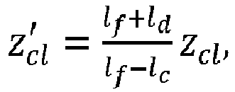

- For two
x-ray sources 11 that are separated by 180° (for example, as shown infigure 5 , α = 0° and α = 180°), the projected z-coordinates may be plotted das a function of δ, i.e., the angle of thedetector 21 position. - A corresponding plot is shown in
figure 7 . The parameters used in the plot are Rf = 580 mm, Rd = 420 mm, Rc = 410 mm, Rfov =250 mm, zcl = 2.7mm, zch =7.3 mm, zdl = 14.3 mm, and zdh = 31.6 mm.Figure 7 illustrates an example of the illumination of adetector 21 by two simultaneously activatedx-ray sources 11 that are separated by 180°, i.e. that are, in this example, positioned at 0° and 180°. In this example, theopening 31 of the beam collimator 3 (defined by zcl, zch) is configured such that it fully illuminates the detector 21 (defined by zdl,zdh) for the whole scan field of view (defined by Rfov) corresponding to theexamination area 4. The curves z'cl and z'ch denote zcl and zch, respectively, being projected onto thedetectors 21. Arrows indicate the projection of the scan field of view onto afirst detector 211 at α=0° and onto asecond detector 212 at α=180°. As can be recognized infigure 7 , the detector is fully illuminated within the projection of the scan field of view and partially illuminated between the projection of the scan field of view and the area defined by the dotted lines. The dotted lines correspond to the dotted lines as shown infigure 5 , designatingbeams 71 not crossing the scan field of view. In this example, the partial illumination rage from thex-ray source 11 at 0° does not cover any part of the scan field of view projection for thex-ray source 11 at 180°, and vice versa. -
Figure 8 shows a plot similar to the one offigure 7 but for three simultaneously activated x-ray sources 11. The x-ray sources 11 are activated such that the simultaneously activatedx-ray sources 11 are spaced equally on the x-ray source array 1 around theexamination area 4. Hence, in this example, the spacing between thex-ray sources 11 is 120°. A scan field of view radius of Rfov = 243 mm is assumed. The illumination of one of thex-ray sources 11 extends into part the detector corresponding to another one of the x-ray sources 11 (i.e., these are unwanted contributions). However, as in the example offigure 7 , theses unwanted contributions are not crossing the scan field of view, i.e. they are not crossing theexamination area 4, and are thus unattenuated. For example, these unattenuated unwanted contributions can be measured in advance and subsequently be subtracted from the measurement. Accordingly, the actual measurement from within theexamination area 4 may thus be improved. - Optionally, if only a small scan field of view or a
small examination area 4 is required, e.g. for a small object, theopening 31 of thebeam collimator 3 may be adapted to achieve a smaller scan field of view. A corresponding plot is shown infigure 9 , where parameters Rfov = 150 mm, zcl = 3.2 mm, and zch = 5.8 mm are used. Correspondingly there is no overlap of signals within the projections of the scan field of view and a separation of the signals can be achieved more easily.
Claims (15)
- A computed tomography system comprising an examination area (4),a static x-ray source array (1) with x-ray sources (11) that are arranged around the examination area (4),a detector arrangement (2) with detectors (21) that are arranged around the examination area (4), anda beam collimator (3) positioned in a radial direction between the x-ray source array (1) and the examination area (4),wherein the computed tomography system is configured to acquire computed tomography scan data of an object or subject (5) placed in the examination area (4) by simultaneously activating at least two x-ray sources (11) and measuring the corresponding signals with the detector arrangement (2) and repeating the simultaneous activation multiple times with different x-ray sources (11) of the x-ray source array (1), respectively, in order to acquire a full scan of the object or subject (5).
- The system according to claim 1,wherein the detector arrangement (2) and the x-ray source array (1) are offset with respect to each other in an axial direction (A) perpendicular to the radial direction,wherein an opening (31) of the beam collimator (3) is offset with respect to both, the x-ray source array (1) and the detector arrangement (2), such that it is positioned between the x-ray source array (1) and the detector arrangement (2) in the axial direction (A).
- The system according to any one of the preceding claims, wherein the detector arrangement (2) is offset with respect to the x-ray source array (1) in the radial direction such that, in the radial direction, the detector arrangement (2) is positioned closer to the examination area (4) than the x-ray source array (1).
- The system according to any one of the preceding claims, wherein the x-ray source array (1), the x-ray sources (11) that are to be activated simultaneously, and the beam collimator (3) are arranged such that, during a scan, none of the detectors (21) simultaneously receives beams from two different x-ray sources (11) that both go through the examination area (4).
- Method for performing a computed tomography scan with a static computed tomography system,the computed tomography system comprising an examination area (4),an x-ray source array (1) with x-ray sources (11) that are arranged around the examination area (4),a detector arrangement (2) with detectors (21) that are arranged around the examination area (4), anda beam collimator (3) positioned in a radial direction between the x-ray source array (1) and the examination area (4),wherein the computed tomography system is in particular the computed tomography system according to any one of the preceding claims,wherein the method comprises the following steps:(a) simultaneously activating at least two x-ray sources (11) and measuring the corresponding signals with the detector arrangement (2) in order to acquire computed tomography scan data of an object or subject (5) placed in the examination area (4);(b) repeating step (a) multiple times with different x-ray sources (11) of the x-ray source array (1), respectively, in order to acquire a full scan of the object or subject (5).
- The method according to claim 5,wherein more than two x-ray sources (11) are activated simultaneously,wherein the x-ray sources (11) are activated such that the simultaneously activated x-ray sources (11) are spaced equally on the x-ray source array (1) around the examination area (4).
- The method according to claim 5,
wherein exactly two x-ray sources (11) are activated simultaneously. - The method according to claim 7,
wherein a smallest angle between the two simultaneously activated x-ray sources (11) on the x-ray source array (1) is smaller than 180°, preferably smaller than 176°, more preferably between 175° and 90°. - The method according to claim 7,
wherein an angle between the two simultaneously activated x-ray sources (11) on the x-ray source array (1) is essentially 180°. - The method according to any one claims 5 to 9,
wherein x-ray sources (11) are activated simultaneously such that none of the detectors (21) simultaneously receives beams from two different x-ray sources (11) that both go through the examination area (4). - The method according to any one claims 5 to 10, comprising a further step of acquiring data with the object or subject (5) not being in the examination area (4) to acquire unattenuated data,
and another further step of using the unattenuated data to adjust the data acquired with the object or subject (5) being in the examination area (4). - The method according to claim 11,
wherein the unattenuated data is acquired for each x-ray source (11) individually. - The method according to claim 11 or 12,
wherein the adjusting is performed for each detector (21) by subtracting the unattenuated data that does not cross the examination area (4) before being detected by the detector (21) from the data acquired with the object or subject (5) being in the examination area (4). - The computed tomography system according to any one of claims 1 to 4,
wherein the computed tomography system is configured to carry out the method according to any one of claims 5 to 13. - A computer program comprising instructions which, when the program is executed by a control unit of a computed tomography system, cause the computed tomography system to carry out the method of any one of claims 5 to 13.
Priority Applications (1)
| Application Number | Priority Date | Filing Date | Title |
|---|---|---|---|
| EP23187885.1A EP4420612B1 (en) | 2023-07-26 | 2023-07-26 | Computed tomography system and method for performing a computed tomography scan |
Applications Claiming Priority (1)
| Application Number | Priority Date | Filing Date | Title |
|---|---|---|---|
| EP23187885.1A EP4420612B1 (en) | 2023-07-26 | 2023-07-26 | Computed tomography system and method for performing a computed tomography scan |
Publications (3)
| Publication Number | Publication Date |
|---|---|
| EP4420612A1 true EP4420612A1 (en) | 2024-08-28 |
| EP4420612C0 EP4420612C0 (en) | 2026-01-21 |
| EP4420612B1 EP4420612B1 (en) | 2026-01-21 |
Family
ID=87473787
Family Applications (1)
| Application Number | Title | Priority Date | Filing Date |
|---|---|---|---|
| EP23187885.1A Active EP4420612B1 (en) | 2023-07-26 | 2023-07-26 | Computed tomography system and method for performing a computed tomography scan |
Country Status (1)
| Country | Link |
|---|---|
| EP (1) | EP4420612B1 (en) |
Citations (3)
| Publication number | Priority date | Publication date | Assignee | Title |
|---|---|---|---|---|
| DE102007014829B3 (en) * | 2007-03-28 | 2008-09-11 | Siemens Ag | Method for scattered radiation correction in imaging X-ray devices and X-ray imaging system |
| WO2016081766A1 (en) * | 2014-11-19 | 2016-05-26 | Besson Guy M | Multi-source ct systems and pre-reconstruction inversion methods |
| US20210383582A1 (en) * | 2020-06-08 | 2021-12-09 | GE Precision Healthcare LLC | Systems and methods for a stationary ct imaging system |
-
2023
- 2023-07-26 EP EP23187885.1A patent/EP4420612B1/en active Active
Patent Citations (3)
| Publication number | Priority date | Publication date | Assignee | Title |
|---|---|---|---|---|
| DE102007014829B3 (en) * | 2007-03-28 | 2008-09-11 | Siemens Ag | Method for scattered radiation correction in imaging X-ray devices and X-ray imaging system |
| WO2016081766A1 (en) * | 2014-11-19 | 2016-05-26 | Besson Guy M | Multi-source ct systems and pre-reconstruction inversion methods |
| US20210383582A1 (en) * | 2020-06-08 | 2021-12-09 | GE Precision Healthcare LLC | Systems and methods for a stationary ct imaging system |
Non-Patent Citations (1)
| Title |
|---|
| FELDKAMP, I.DAVIS, LKRESS: "J. Practical cone-beam algorithm Journal of the Optical Society of America A", OPTICS AND IMAGE SCIENCE, AND VISION, vol. 1, 1984, pages 612 - 619 |
Also Published As
| Publication number | Publication date |
|---|---|
| EP4420612C0 (en) | 2026-01-21 |
| EP4420612B1 (en) | 2026-01-21 |
Similar Documents
| Publication | Publication Date | Title |
|---|---|---|
| JP4663150B2 (en) | Method and apparatus for region of interest multi-slice CT scanning | |
| US7113569B2 (en) | X-ray CT apparatus | |
| US7778383B2 (en) | Effective dual-energy x-ray attenuation measurement | |
| US7072436B2 (en) | Volumetric computed tomography (VCT) | |
| US6501828B1 (en) | Method and apparatus for influencing X-rays in a beam path | |
| JP5582514B2 (en) | X-ray CT system | |
| US6370218B1 (en) | Methods and systems for determining x-ray beam position in multi-slice computed tomography scanners | |
| EP1605826B1 (en) | Computerized tomographic imaging system | |
| EP1304077A2 (en) | X-ray computed tomography apparatus | |
| US7050529B2 (en) | Methods and apparatus for performing a computed tomography scan | |
| US20090135994A1 (en) | System And Method For Creating Mixed Image From Dual-Energy CT Data | |
| US7187748B2 (en) | Multidetector CT imaging method and apparatus with reducing radiation scattering | |
| US20110188725A1 (en) | Method for reconstruction in dual energy, dual source helical computed tomography | |
| EP1387321A2 (en) | Methods and apparatus for weighting of computed tomography data | |
| US20060002506A1 (en) | Volumetric computed tomography (VCT) | |
| US8050479B2 (en) | Method and system for generating a computed tomography image | |
| JP2012130687A (en) | Anode target for x-ray tube and method for controlling x-ray tube | |
| JP2009125250A (en) | X-ray ct equipment | |
| IL137107A (en) | Methods and apparatus for noise compensation in imaging systems | |
| US6269139B1 (en) | Methods and apparatus for pre-filtering weighting in image reconstruction | |
| EP4420612B1 (en) | Computed tomography system and method for performing a computed tomography scan | |
| JP2008012206A (en) | X-ray tomographic apparatus | |
| EP1077045A2 (en) | Projection data correction method and apparatus, and radiation tomographic imaging method and apparatus | |
| JP5022690B2 (en) | Radiography equipment | |
| JP4887132B2 (en) | X-ray CT system |
Legal Events
| Date | Code | Title | Description |
|---|---|---|---|
| PUAI | Public reference made under article 153(3) epc to a published international application that has entered the european phase |
Free format text: ORIGINAL CODE: 0009012 |
|
| STAA | Information on the status of an ep patent application or granted ep patent |
Free format text: STATUS: THE APPLICATION HAS BEEN PUBLISHED |
|
| AK | Designated contracting states |
Kind code of ref document: A1 Designated state(s): AL AT BE BG CH CY CZ DE DK EE ES FI FR GB GR HR HU IE IS IT LI LT LU LV MC ME MK MT NL NO PL PT RO RS SE SI SK SM TR |
|
| STAA | Information on the status of an ep patent application or granted ep patent |
Free format text: STATUS: REQUEST FOR EXAMINATION WAS MADE |
|
| 17P | Request for examination filed |
Effective date: 20250220 |
|
| GRAP | Despatch of communication of intention to grant a patent |
Free format text: ORIGINAL CODE: EPIDOSNIGR1 |
|
| STAA | Information on the status of an ep patent application or granted ep patent |
Free format text: STATUS: GRANT OF PATENT IS INTENDED |
|
| RIC1 | Information provided on ipc code assigned before grant |
Ipc: A61B 6/03 20060101AFI20250909BHEP Ipc: A61B 6/40 20240101ALI20250909BHEP Ipc: A61B 6/42 20240101ALI20250909BHEP |
|
| INTG | Intention to grant announced |
Effective date: 20250923 |
|
| GRAS | Grant fee paid |
Free format text: ORIGINAL CODE: EPIDOSNIGR3 |
|
| GRAA | (expected) grant |
Free format text: ORIGINAL CODE: 0009210 |
|
| STAA | Information on the status of an ep patent application or granted ep patent |
Free format text: STATUS: THE PATENT HAS BEEN GRANTED |
|
| AK | Designated contracting states |
Kind code of ref document: B1 Designated state(s): AL AT BE BG CH CY CZ DE DK EE ES FI FR GB GR HR HU IE IS IT LI LT LU LV MC ME MK MT NL NO PL PT RO RS SE SI SK SM TR |
|
| REG | Reference to a national code |
Ref country code: CH Ref legal event code: F10 Free format text: ST27 STATUS EVENT CODE: U-0-0-F10-F00 (AS PROVIDED BY THE NATIONAL OFFICE) Effective date: 20260121 |
|
| REG | Reference to a national code |
Ref country code: IE Ref legal event code: FG4D |
|
| U01 | Request for unitary effect filed |
Effective date: 20260121 |
|
| U07 | Unitary effect registered |
Designated state(s): AT BE BG DE DK EE FI FR IT LT LU LV MT NL PT RO SE SI Effective date: 20260126 |