EP4420577A1 - Outil de travail rotatif a ejection amelioree - Google Patents
Outil de travail rotatif a ejection amelioree Download PDFInfo
- Publication number
- EP4420577A1 EP4420577A1 EP24158269.1A EP24158269A EP4420577A1 EP 4420577 A1 EP4420577 A1 EP 4420577A1 EP 24158269 A EP24158269 A EP 24158269A EP 4420577 A1 EP4420577 A1 EP 4420577A1
- Authority
- EP
- European Patent Office
- Prior art keywords
- working tool
- side wall
- circumferential side
- food
- housing
- Prior art date
- Legal status (The legal status is an assumption and is not a legal conclusion. Google has not performed a legal analysis and makes no representation as to the accuracy of the status listed.)
- Pending
Links
- 235000013305 food Nutrition 0.000 claims abstract description 87
- 238000007599 discharging Methods 0.000 claims abstract 2
- 230000005540 biological transmission Effects 0.000 claims description 19
- 239000002184 metal Substances 0.000 claims description 13
- 238000013459 approach Methods 0.000 claims description 4
- 238000010276 construction Methods 0.000 description 5
- 238000009825 accumulation Methods 0.000 description 2
- 230000000295 complement effect Effects 0.000 description 2
- 239000012634 fragment Substances 0.000 description 2
- 235000013351 cheese Nutrition 0.000 description 1
- 239000003638 chemical reducing agent Substances 0.000 description 1
- 238000009434 installation Methods 0.000 description 1
- 238000012986 modification Methods 0.000 description 1
- 230000004048 modification Effects 0.000 description 1
- 210000000056 organ Anatomy 0.000 description 1
- 229910001220 stainless steel Inorganic materials 0.000 description 1
- 239000010935 stainless steel Substances 0.000 description 1
- 235000013311 vegetables Nutrition 0.000 description 1
Images


Classifications
-
- A—HUMAN NECESSITIES
- A47—FURNITURE; DOMESTIC ARTICLES OR APPLIANCES; COFFEE MILLS; SPICE MILLS; SUCTION CLEANERS IN GENERAL
- A47J—KITCHEN EQUIPMENT; COFFEE MILLS; SPICE MILLS; APPARATUS FOR MAKING BEVERAGES
- A47J43/00—Implements for preparing or holding food, not provided for in other groups of this subclass
- A47J43/04—Machines for domestic use not covered elsewhere, e.g. for grinding, mixing, stirring, kneading, emulsifying, whipping or beating foodstuffs, e.g. power-driven
- A47J43/07—Parts or details, e.g. mixing tools, whipping tools
- A47J43/0716—Parts or details, e.g. mixing tools, whipping tools for machines with tools driven from the lower side
- A47J43/0722—Mixing, whipping or cutting tools
-
- A—HUMAN NECESSITIES
- A47—FURNITURE; DOMESTIC ARTICLES OR APPLIANCES; COFFEE MILLS; SPICE MILLS; SUCTION CLEANERS IN GENERAL
- A47J—KITCHEN EQUIPMENT; COFFEE MILLS; SPICE MILLS; APPARATUS FOR MAKING BEVERAGES
- A47J43/00—Implements for preparing or holding food, not provided for in other groups of this subclass
- A47J43/25—Devices for grating
- A47J43/255—Devices for grating with grating discs or drums
-
- B—PERFORMING OPERATIONS; TRANSPORTING
- B26—HAND CUTTING TOOLS; CUTTING; SEVERING
- B26D—CUTTING; DETAILS COMMON TO MACHINES FOR PERFORATING, PUNCHING, CUTTING-OUT, STAMPING-OUT OR SEVERING
- B26D1/00—Cutting through work characterised by the nature or movement of the cutting member or particular materials not otherwise provided for; Apparatus or machines therefor; Cutting members therefor
- B26D1/01—Cutting through work characterised by the nature or movement of the cutting member or particular materials not otherwise provided for; Apparatus or machines therefor; Cutting members therefor involving a cutting member which does not travel with the work
- B26D1/12—Cutting through work characterised by the nature or movement of the cutting member or particular materials not otherwise provided for; Apparatus or machines therefor; Cutting members therefor involving a cutting member which does not travel with the work having a cutting member moving about an axis
- B26D1/25—Cutting through work characterised by the nature or movement of the cutting member or particular materials not otherwise provided for; Apparatus or machines therefor; Cutting members therefor involving a cutting member which does not travel with the work having a cutting member moving about an axis with a non-circular cutting member
- B26D1/26—Cutting through work characterised by the nature or movement of the cutting member or particular materials not otherwise provided for; Apparatus or machines therefor; Cutting members therefor involving a cutting member which does not travel with the work having a cutting member moving about an axis with a non-circular cutting member moving about an axis substantially perpendicular to the line of cut
- B26D1/28—Cutting through work characterised by the nature or movement of the cutting member or particular materials not otherwise provided for; Apparatus or machines therefor; Cutting members therefor involving a cutting member which does not travel with the work having a cutting member moving about an axis with a non-circular cutting member moving about an axis substantially perpendicular to the line of cut and rotating continuously in one direction during cutting
-
- B—PERFORMING OPERATIONS; TRANSPORTING
- B26—HAND CUTTING TOOLS; CUTTING; SEVERING
- B26D—CUTTING; DETAILS COMMON TO MACHINES FOR PERFORATING, PUNCHING, CUTTING-OUT, STAMPING-OUT OR SEVERING
- B26D2210/00—Machines or methods used for cutting special materials
- B26D2210/02—Machines or methods used for cutting special materials for cutting food products, e.g. food slicers
-
- B—PERFORMING OPERATIONS; TRANSPORTING
- B26—HAND CUTTING TOOLS; CUTTING; SEVERING
- B26D—CUTTING; DETAILS COMMON TO MACHINES FOR PERFORATING, PUNCHING, CUTTING-OUT, STAMPING-OUT OR SEVERING
- B26D7/00—Details of apparatus for cutting, cutting-out, stamping-out, punching, perforating, or severing by means other than cutting
- B26D7/06—Arrangements for feeding or delivering work of other than sheet, web, or filamentary form
- B26D7/0608—Arrangements for feeding or delivering work of other than sheet, web, or filamentary form by pushers
Definitions
- the present invention relates to the technical field of food preparation devices comprising a drum-type rotating working tool for progressively cutting food.
- the present invention relates more particularly, but not exclusively, to household appliances for food preparation comprising a motorized housing carrying a removable accessory forming a food preparation device of the aforementioned type.
- the present invention also relates to removable accessories of the aforementioned type.
- cylindrical or truncated cone-shaped rotating work tools to slice or thin foods, particularly vegetables or cheese.
- These rotating work tools form a drum having a drive member arranged at one of its ends, and a circumferential wall on which cutting members are arranged.
- the cut foods are received inside the drum and are evacuated through an open end arranged opposite the drive member.
- some cut foods may form clumps inside the drum.
- the document US1527087 proposes a food cutting device comprising a cylindrical food cutting drum mounted on a support comprising an arm extending inside the drum to facilitate the evacuation of food from the drum.
- a disadvantage of this embodiment is that the installation and removal of the drum are not very ergonomic.
- the document EP3082533 proposes a food cutting device comprising a truncated cone-shaped food cutting drum rotated in a magazine and a food ejection member mounted on said magazine and extending inside said drum.
- a disadvantage of this embodiment is that it requires additional handling for the in place or removal of the food ejection organ.
- the present invention aims to remedy these drawbacks.
- the technical problem underlying the invention is to simplify the construction of a food cutting device having improved food ejection.
- a first aspect of the invention relates to a rotary working tool comprising a rotary drive member and a circumferential side wall having at least one external cutting member, in which the ejection of food is improved.
- Another aspect of the invention relates to a food preparation device comprising a rotary working tool comprising a rotary drive member and a circumferential side wall having at least one external cutting member, in which the ejection of food is improved.
- a rotary working tool comprising a drive member rotating about an axis of rotation and a circumferential side wall extending about the axis of rotation, the circumferential side wall having at least one external cutting member having a leading edge adjacent to a through passage formed in the circumferential side wall, the circumferential side wall having a circumferential edge forming a front opening for evacuating the cut food, because the inner face of the circumferential side wall carries at least one internal rib configured to eject the cut food toward the front opening during rotation of the rotary working tool for cutting the food.
- the internal rib(s) tend to push the cut food toward the front opening, which helps to prevent the phenomena of accumulation of cut food inside the working tool.
- Said at least one internal rib can approach the circumferential edge when traveled in a direction from the through passage to the adjacent leading edge.
- said at least one internal rib can along its entire length approach the circumferential edge when traveled in a direction from the through passage to the adjacent leading edge.
- Said at least one internal rib may extend over at least 90° around the axis of rotation, and preferably over at least 120° around the axis of rotation.
- Said at least one internal rib may extend to the circumferential edge. This arrangement makes it possible to promote the ejection of the cut food.
- Said at least one internal rib may be overmolded onto the inner face of the circumferential side wall. This arrangement makes it possible to obtain an economical construction. Alternatively, said internal rib may in particular be clipped onto the inner face of the circumferential side wall.
- Said at least one internal rib may have a helical configuration. This arrangement makes it possible to promote the ejection of cut food.
- the rotary working tool may include a bottom wall arranged opposite the front opening and the at least one internal rib may extend from the bottom wall. This arrangement helps promote ejection of the cut food by preventing the accumulation of cut food at the bottom of the working tool.
- the inner face of the circumferential sidewall may carry a plurality of internal ribs configured to eject the cut food toward the front opening upon rotation of the rotary working tool for cutting the food. This arrangement helps promote the ejection of the food cut out.
- the inner face of the circumferential side wall may carry 2 to 6 internal ribs configured to eject the cut food toward the front opening upon rotation of the rotary working tool for cutting the food. This arrangement helps promote the ejection of the cut food.
- the internal ribs may be regularly distributed on the inner face of the circumferential side wall.
- the circumferential sidewall may comprise a circumferential metal portion having the through passages, said at least one external cutting member being derived from the circumferential metal portion.
- the circumferential edge can then be overmolded onto one end of the circumferential metal part.
- the rotation drive member may be carried by a drive end overmolded on the other end of the circumferential metal part.
- the circumferential sidewall may have a plurality of external cutting members each having a leading edge adjacent a through passage formed in the circumferential sidewall.
- the circumferential sidewall may have a frustoconical geometry.
- the circumferential sidewall may also have a cylindrical geometry or a conical geometry.
- the food preparation device may include a pusher movable within the feed chute to push food toward the work tool. Such an arrangement improves the food cutting rate.
- the housing may carry a transmission member mounted to rotate freely, the drive member of the working tool mounted in the housing then engaging with the transmission member to drive the working tool in rotation.
- the food preparation device may comprise a motorized base carrying the housing, the work tool mounted in the housing being driven by an electric motor disposed in the motorized base, if desired via the transmission member.
- the housing can be mounted removable from the motorized base.
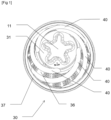
- the rotating working tool 30 comprises a drive member 11 rotating about an axis of rotation R and a circumferential side wall 32 extending around the axis of rotation R.
- the circumferential side wall 32 has a circumferential edge 37 forming a front opening 36 for evacuating the cut food.
- the drive member 11 rotating is carried by a drive end 31 arranged opposite the circumferential edge 37.
- the working tool 30 comprises a bottom wall 12 arranged opposite the front opening 36.
- the drive member 11 is formed in the bottom wall 12.
- the bottom wall 12 forms the drive end 31.
- the circumferential side wall 32 has a frustoconical geometry.
- the circumferential side wall 32 flares towards the circumferential edge 37, to facilitate the evacuation of the cut food.
- a cylindrical geometry or a conical geometry may in particular be envisaged for the circumferential side wall 32.
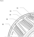
- the circumferential side wall 32 has at least one external cutting member 33 having a leading edge 34 adjacent to a through passage 35 formed in the circumferential side wall 32.
- the circumferential side wall 32 has a plurality of external cutting members 33 each having a leading edge 34 adjacent to a through passage 35 formed in the circumferential side wall 32.
- a plurality of external cutting members 33 are arranged on the circumferential side wall 32 between the bottom wall 12 and the front opening 36.
- the external cutting members 33 of the exemplary embodiment illustrated in the Figures 1 to 3 are provided for shredding food.
- other types of external cutting members 33 may be envisaged, for example elongated external cutting members 33 provided for slicing food.
- the circumferential side wall 32 has a plurality of external cutting members 33 each having a leading edge 34 adjacent to a through passage 35 formed in the circumferential side wall 32.
- the inner face of the circumferential side wall 32 carries at least one internal rib 40 configured to eject the cut food toward the front opening 36 upon rotation of the rotary working tool 30 for cutting the food.
- said at least one internal rib 40 approaches the circumferential edge 37 when traveled in a direction from the through passage 35 to the adjacent leading edge 34.
- the inner face of the circumferential side wall 32 carries four internal ribs 40 configured to eject the cut food toward the front opening 36 during rotation of the rotary working tool 30 for cutting the food.
- the internal ribs 40 are regularly distributed on the inner face of the circumferential side wall 32.
- the inner face of the circumferential side wall 32 may carry a plurality of internal ribs 40 configured to eject the cut food toward the front opening 36 during rotation of the rotary working tool 30 for cutting the food.
- the inner face of the circumferential side wall 32 may in particular carry from 2 to 6 internal ribs 40 configured to eject the cut food toward the front opening 36 upon rotation of the rotary working tool 30 for cutting the food.
- the inner face of the circumferential side wall 32 may carry a single internal rib 40 configured to eject the cut food toward the front opening 36 upon rotation of the rotary working tool 30 for cutting the food.
- the internal ribs 40 extend over approximately half of the circumference of the circumferential side wall 32.
- the internal ribs 40 may extend over at least 90° around the axis of rotation R, and preferably over at least 120° around the axis of rotation R.
- the internal ribs 40 extend to the circumferential edge 37.
- the internal ribs 40 extend from the bottom wall 12.
- the internal ribs 40 have a helical configuration.
- the circumferential side wall 32 comprises a circumferential metal part 38 having the through passages 35.
- the circumferential metal part 38 is for example made of stainless steel.
- the external cutting members 33 are derived from the circumferential metal part 38.
- the working tool 30 has an overmolded construction.
- the circumferential edge 37 is overmolded on one end of the circumferential metal part 38 to form the front opening 36.
- the drive end 31 is overmolded on the other end of the circumferential metal part 38.
- the circumferential edge 37 and the drive end 31 are for example made of plastic.
- the internal ribs 40 are overmolded on the inner face of the circumferential side wall 32.
- the internal ribs 40 are for example made of plastic.
- the food preparation device illustrated in the figure 4 comprises a housing 20 receiving the rotatable working tool 30.
- the housing 20 defines a housing 21 having a mounting opening 22 for the placement of the working tool. 30 in the housing 21.
- the housing 20 has a chimney 23 for introducing the food to be cut.
- the chimney 23 opens into the housing 21 at least partially opposite said at least one external cutting member 33 of the working tool 30 arranged in the housing 21.
- the food preparation device comprises a pusher 24 movable in the chimney 23 to push the food towards the working tool 30 mounted in the housing 20.
- the food preparation device illustrated in the figure 4 comprises a motorized base 1 carrying the housing 20.
- the motorized base 1 houses an electric motor 3 controlled by a control device 4.
- the electric motor 3 is connected to a drive output 5, if desired via a transmission device 6.
- the transmission device 6 may comprise a reducer.
- the rotational speed of the drive output 5 may be variable.
- the rotational speed of the drive output 5 is located and/or is included in the speed range between 100 and 300 rpm.
- the working tool 30 mounted in the housing 21 is driven by the electric motor 3 arranged in the motorized base 1.
- the housing 20 is removably mounted relative to the motorized base 1.
- the housing 20 comprises for this purpose fixing means 10 provided to engage with complementary fixing means 7 of the motorized base 1.
- the housing 20 and the rotating work tool 30 belong to a rotating work accessory 2.
- the rotating work accessory 2 is thus removable relative to the motorized base 1.
- the pusher 24 also belongs to the rotating work accessory 2.
- the fixing means 10 and the complementary fixing means 7 are bayonet fixing means.
- other fixing means may be used, in particular a locking ring assembled by screwing or by bayonet, or even retaining hooks.
- the housing 20 carries a transmission member 25 mounted to rotate freely.
- the axis of rotation of the transmission member 25 corresponds to the axis of rotation R of the working tool 30.
- the axis of rotation of the transmission member 25 is inclined downwards towards the mounting opening 22. This arrangement makes it possible to improve the tilting character of the rotating working tool 30.
- the transmission member 25 is driven by the drive output 5 and engages with the working tool 30 arranged in the housing 21.
- the transmission member 25 has a first end 26 engaging with the drive output 5.
- the first end 26 is for example formed by a shaft of hexagonal or square section.
- the transmission member 25 has a second end 27 arranged in the housing 21, intended to rotate the working tool 30 arranged in the housing 21.
- the second end 27 may have lugs for retaining the working tool 30 arranged in the housing 21. If desired, the lugs can form hooks.
- the drive member 11 of the working tool 30 mounted in the housing 21 engages with the transmission member 25 to drive the working tool 30 in rotation.
- the working tool 30 mounted in the housing 21 is driven by the electric motor 3 arranged in the motorized base 1 via the transmission member 25.
- the housing 21 is overhanging towards the mounting opening 22.
- the housing 20 has a lower stop 29 for retaining the working tool 30 arranged in the housing 21.
- the lower stop 29 is formed near the mounting opening 22.
- the food preparation device illustrated in the figure 4 works and is used in the following manner.
- the user mounts the housing 20 on the motorized base 1 and places the work tool 30 in the housing 21 of the housing 20.
- the drive member 11 of the work tool 30 mounted in the housing 21 engages with the transmission member 25 to drive the work tool 30 in rotation.
- the user can start the food preparation device by operating the control device 4.
- the working tool 30 arranged in the housing 21 of the housing 20 mounted on the motorized base 1 is driven in rotation by the transmission member 25.
- the working tool 30 is preferably driven at rotation speeds between 100 and 200 rpm, to obtain a sufficient flow rate.
- the external cutting members 33 then pass under the base of the chimney 23 to cut into the base of the food introduced into the chimney 23.
- the leading edges 34 cut fragments of food which are evacuated by the through passages 35 of the circumferential side wall 32.
- the internal ribs 40 then contribute to evacuating the fragments of food towards the front opening 36 of the working tool 30. The evacuation of the cut food is thus facilitated, which makes it possible to avoid jamming phenomena inside the working tool 30.
- the working tool 30 has a simple structure and can be substituted for or by another working tool.
- a multifunctional food preparation device having a simple structure can thus be obtained.
- the housing 20 does not necessarily include a transmission member 25.
- the drive member 11 of the work tool 30 can in particular be driven by the drive output 5 of the motorized base 1.
- the housing 20 is not necessarily removable relative to the motorized base 1.
- the housing 20 may in particular come from the motorized base 1.
- circumferential sidewall 32 is not necessarily entirely metallic.
- the internal rib(s) 40 are not necessarily overmolded.
- the internal rib(s) 40 may in particular be clipped inside the circumferential side wall 32.
Landscapes
- Engineering & Computer Science (AREA)
- Mechanical Engineering (AREA)
- Food Science & Technology (AREA)
- Life Sciences & Earth Sciences (AREA)
- Forests & Forestry (AREA)
- Drilling Tools (AREA)
- Food-Manufacturing Devices (AREA)
Abstract
L'invention concerne un outil de travail (30) rotatif comportant un organe d'entraînement (11) en rotation selon un axe de rotation (R) et une paroi latérale circonférentielle (32) présentant au moins un organe de découpe externe (33) présentant un bord d'attaque (34) adjacent à un passage traversant (35) ménagé dans la paroi latérale circonférentielle (32), la paroi latérale circonférentielle (32) présentant une bordure circonférentielle (37) ménageant une ouverture frontale (36) pour l'évacuation des aliments découpés.Selon l'invention, la face intérieure de la paroi latérale circonférentielle (32) porte au moins une nervure interne (40) configurée pour éjecter les aliments découpés vers l'ouverture frontale (36) lors de la rotation de l'outil de travail (30).L'invention concerne également un dispositif de préparation d'aliments comprenant un outil de travail (30) rotatif du type précité et un boîtier définissant un logement présentant une ouverture de montage pour la mise en place de l'outil de travail (30).
Description
- La présente invention concerne le domaine technique des dispositifs de préparation d'aliments comportant un outil de travail rotatif de type tambour pour découper progressivement les aliments.
- La présente invention concerne plus particulièrement, mais non exclusivement, les appareils électroménagers de préparation culinaire comportant un boîtier motorisé portant un accessoire amovible formant un dispositif de préparation d'aliments du type précité. La présente invention concerne également les accessoires amovibles du type précité.
- Il est connu d'utiliser des outils de travail rotatifs cylindriques ou tronconiques pour émincer ou pour effiler les aliments, notamment des légumes ou du fromage. Ces outils de travail rotatifs forment un tambour présentant une un organe d'entraînement agencé à l'une de ses extrémités, et une paroi circonférentielle sur laquelle sont agencés des organes de coupe. Les aliments découpés sont reçus à l'intérieur du tambour et sont évacués par une extrémité ouverte disposée à l'opposé de l'organe d'entrainement. Toutefois certains aliments découpés peuvent former des amas à l'intérieur du tambour.
- Le document
US1527087 propose un dispositif de découpe d'aliments comportant un tambour cylindrique de découpe d'aliments monté sur un support comportant un bras s'étendant à l'intérieur du tambour pour faciliter l'évacuation des aliments hors du tambour. Un inconvénient de cette réalisation est que la mise en place et le retrait du tambour sont peu ergonomiques. - Le document
EP3082533 propose un dispositif de découpe d'aliments comportant un tambour tronconique de découpe d'aliments entrainé en rotation dans un magasin ainsi qu'un organe d'éjection d'aliments monté sur ledit magasin et s'étendant à l'intérieur dudit tambour. Un inconvénient de cette réalisation est qu'elle nécessite une manipulation supplémentaire pour la mise en place ou le retrait de l'organe d'éjections d'aliments. - La présente invention vise à remédier à ces inconvénients.
- Le problème technique à la base de l'invention consiste à simplifier la construction d'un dispositif de découpe d'aliments présentant une éjection d'aliments améliorée.
- A cet effet, un premier aspect de l'invention a pour objet un outil de travail rotatif comportant un organe d'entraînement en rotation et une paroi latérale circonférentielle présentant au moins un organe de découpe externe, dans lequel l'éjection des aliments est améliorée.
- Un autre aspect de l'invention a pour objet un dispositif de préparation d'aliments comportant un outil de travail rotatif comportant un organe d'entraînement en rotation et une paroi latérale circonférentielle présentant au moins un organe de découpe externe, dans lequel l'éjection des aliments est améliorée.
- Ces objets sont atteints avec un outil de travail rotatif comportant un organe d'entraînement en rotation selon un axe de rotation et une paroi latérale circonférentielle s'étendant autour de l'axe de rotation, la paroi latérale circonférentielle présentant au moins un organe de découpe externe présentant un bord d'attaque adjacent à un passage traversant ménagé dans la paroi latérale circonférentielle, la paroi latérale circonférentielle présentant une bordure circonférentielle ménageant une ouverture frontale pour l'évacuation des aliments découpés, du fait que la face intérieure de la paroi latérale circonférentielle porte au moins une nervure interne configurée pour éjecter les aliments découpés vers l'ouverture frontale lors de la rotation de l'outil de travail rotatif pour découper les aliments. Ainsi lors de la rotation de l'outil de travail la ou les nervures internes tendent à repousser les aliments découpés vers l'ouverture frontale, ce qui contribue à éviter les phénomènes d'accumulation d'aliments découpés à l'intérieur de l'outil de travail.
- Ladite au moins une nervure interne peut se rapprocher de la bordure circonférentielle lorsque parcourue dans une direction allant du passage traversant au bord d'attaque adjacent. De préférence, ladite au moins une nervure interne peut sur toute sa longueur se rapprocher de la bordure circonférentielle lorsque parcourue dans une direction allant du passage traversant au bord d'attaque adjacent.
- Ladite au moins une nervure interne peut s'étendre sur au moins 90° autour de l'axe de rotation, et de préférence sur au moins 120° autour de l'axe de rotation. Ces dispositions permettent de favoriser l'éjection des aliments découpés.
- Ladite au moins une nervure interne peut s'étendre jusqu'à la bordure circonférentielle. Cette disposition permet de favoriser l'éjection des aliments découpés.
- Ladite au moins une nervure interne peut être surmoulée sur la face intérieure de la paroi latérale circonférentielle. Cette disposition permet d'obtenir une construction économique. En alternative ladite nervure interne peut notamment être clipsée sur a face intérieure de la paroi latérale circonférentielle.
- Ladite au moins une nervure interne peut présenter une configuration hélicoïdale. Cette disposition permet de favoriser l'éjection des aliments découpés.
- L'outil de travail rotatif peut comporter une paroi de fond agencée à l'opposé de l'ouverture frontale et ladite au moins une nervure interne peut s'étendre à partir de la paroi de fond. Cette disposition permet de favoriser l'éjection des aliments découpés en évitant l'accumulation d'aliments découpés au fond de l'outil de travail.
- La face intérieure de la paroi latérale circonférentielle peut porter une pluralité de nervures internes configurées pour éjecter les aliments découpés vers l'ouverture frontale lors de la rotation de l'outil de travail rotatif pour découper les aliments. Cette disposition permet de favoriser l'éjection des aliments découpés.
- La face intérieure de la paroi latérale circonférentielle peut porter de 2 à 6 nervures internes configurées pour éjecter les aliments découpés vers l'ouverture frontale lors de la rotation de l'outil de travail rotatif pour découper les aliments. Cette disposition permet de favoriser l'éjection des aliments découpés.
- Les nervures internes peuvent être régulièrement réparties sur la face intérieure de la paroi latérale circonférentielle.
- La paroi latérale circonférentielle peut comprendre une partie métallique circonférentielle présentant les passages traversants, ledit au moins un organe de découpe externe étant issu de la partie métallique circonférentielle. Une telle construction permet d'obtenir une bonne qualité de coupe avec une construction économique.
- La bordure circonférentielle peut alors être surmoulée sur l'une des extrémités de la partie métallique circonférentielle.
- L'organe d'entrainement en rotation peut être porté par une extrémité d'entraînement surmoulée sur l'autre extrémité de la partie métallique circonférentielle.
- La paroi latérale circonférentielle peut présenter une pluralité d'organes de découpe externes présentant chacun un bord d'attaque adjacent à un passage traversant ménagé dans la paroi latérale circonférentielle.
- La paroi latérale circonférentielle peut présenter une géométrie tronconique. La paroi latérale circonférentielle peut aussi présenter une géométrie cylindrique ou une géométrie conique.
- Ces objets sont atteints également avec un dispositif de préparation d'aliments comprenant :
- un outil de travail rotatif comportant un organe d'entraînement en rotation selon un axe de rotation et une paroi latérale circonférentielle s'étendant autour de l'axe de rotation, la paroi latérale circonférentielle présentant au moins un organe de découpe externe adjacent à un passage traversant, la paroi latérale circonférentielle présentant une bordure circonférentielle ménageant une ouverture frontale pour l'évacuation des aliments découpés,
- un boîtier définissant un logement présentant une ouverture de montage pour la mise en place de l'outil de travail dans le logement, le boîtier présentant une cheminée pour l'introduction des aliments à découper, la cheminée débouchant dans le logement au moins partiellement en regard dudit au moins un organe de découpe externe,
- Le dispositif de préparation d'aliments peut comporter un poussoir pouvant être déplacé dans la cheminée pour pousser les aliments vers l'outil de travail. Une telle disposition permet d'améliorer le débit de découpe des aliments.
- Le boîtier peut porter un organe de transmission monté libre en rotation, l'organe d'entraînement de l'outil de travail monté dans le logement venant alors en prise avec l'organe de transmission pour entraîner en rotation l'outil de travail.
- Le dispositif de préparation d'aliments peut comporter une base motorisée portant le boîtier, l'outil de travail monté dans le logement étant entrainé par un moteur électrique disposé dans la base motorisée, si désiré par l'intermédiaire de l'organe de transmission.
- Le boîtier peut être monté amovible par rapport à la base motorisée.
- On comprendra mieux les buts, aspects et avantages de la présente invention, d'après la description donnée ci-après d'un mode particulier de réalisation de l'invention présenté à titre d'exemple non limitatif, en se référant aux dessins annexés dans lesquels :
- La
figure 1 est une vue en perspective d'un exemple de réalisation d'un outil de travail rotatif selon l'invention selon une première orientation ; - La
figure 2 est une vue en perspective de l'exemple de réalisation d'un outil de travail rotatif selon l'invention illustré sur lafigure 1 selon une deuxième orientation ; - La
figure 3 est une vue partielle en perspective de l'exemple de réalisation d'un outil de travail rotatif selon l'invention illustré sur lesfigures 1 et2 ; - La
figure 4 est une vue en coupe d'un dispositif de préparation d'aliments motorisé comportant l'exemple de réalisation d'un outil de travail rotatif selon l'invention illustré sur lesfigures 1 à 3 . - Un exemple de réalisation d'un outil de travail 30 rotatif selon l'invention est illustré sur les
figures 1 à 3 . L'outil de travail 30 rotatif comporte un organe d'entraînement 11 en rotation selon un axe de rotation R et une paroi latérale circonférentielle 32 s'étendant autour de l'axe de rotation R. La paroi latérale circonférentielle 32 présente une bordure circonférentielle 37 ménageant une ouverture frontale 36 pour l'évacuation des aliments découpés. L'organe d'entraînement 11 en rotation est porté par une extrémité d'entraînement 31 agencée à l'opposé de la bordure circonférentielle 37. L'outil de travail 30 comporte une paroi de fond 12 agencée à l'opposé de l'ouverture frontale 36. L'organe d'entraînement 11 est formé dans la paroi de fond 12. Ainsi la paroi de fond 12 forme l'extrémité d'entraînement 31. - Dans l'exemple de réalisation illustré sur les
figures 1 à 3 , la paroi latérale circonférentielle 32 présente une géométrie tronconique. La paroi latérale circonférentielle 32 s'évase en direction de la bordure circonférentielle 37, pour faciliter l'évacuation des aliments découpés. A titre de variante, une géométrie cylindrique ou une géométrie conique peuvent notamment être envisagées pour la paroi latérale circonférentielle 32. - La paroi latérale circonférentielle 32 présente au moins un organe de découpe externe 33 présentant un bord d'attaque 34 adjacent à un passage traversant 35 ménagé dans la paroi latérale circonférentielle 32.
- Dans l'exemple de réalisation illustré sur les
figures 1 à 3 , la paroi latérale circonférentielle 32 présente plusieurs organes de découpe externe 33 présentant chacun bord d'attaque 34 adjacent à un passage traversant 35 ménagé dans la paroi latérale circonférentielle 32. Plusieurs organes de découpe externe 33 sont agencés sur la paroi latérale circonférentielle 32 entre la paroi de fond 12 et l'ouverture frontale 36. Les organes de découpe externe 33 de l'exemple de réalisation illustré sur lesfigures 1 à 3 sont prévus pour effiler les aliments. A titre de variante, d'autres types d'organe de découpe externe 33 peuvent être envisagés, par exemple des organes de découpe externe 33 allongés prévus pour trancher les aliments. - Dans l'exemple de réalisation illustré sur les
figures 1 à 3 , la paroi latérale circonférentielle 32 présente une pluralité d'organes de découpe externe 33 présentant chacun un bord d'attaque 34 adjacent à un passage traversant 35 ménagé dans la paroi latérale circonférentielle 32. - La face intérieure de la paroi latérale circonférentielle 32 porte au moins une nervure interne 40 configurée pour éjecter les aliments découpés vers l'ouverture frontale 36 lors de la rotation de l'outil de travail 30 rotatif pour découper les aliments. Tel que bien visible sur la
figure 2 , ladite au moins une nervure interne 40 se rapproche de la bordure circonférentielle 37 lorsque parcourue dans une direction allant du passage traversant 35 au bord d'attaque 34 adjacent. - Dans l'exemple de réalisation illustré sur les
figures 1 à 3 , la face intérieure de la paroi latérale circonférentielle 32 porte quatre nervures internes 40 configurées pour éjecter les aliments découpés vers l'ouverture frontale 36 lors de la rotation de l'outil de travail 30 rotatif pour découper les aliments. Les nervures internes 40 sont régulièrement réparties sur la face intérieure de la paroi latérale circonférentielle 32. A titre de variante la face intérieure de la paroi latérale circonférentielle 32 peut porter une pluralité de nervures internes 40 configurées pour éjecter les aliments découpés vers l'ouverture frontale 36 lors de la rotation de l'outil de travail 30 rotatif pour découper les aliments. La face intérieure de la paroi latérale circonférentielle 32 peut notamment porter de 2 à 6 nervures internes 40 configurées pour éjecter les aliments découpés vers l'ouverture frontale 36 lors de la rotation de l'outil de travail 30 rotatif pour découper les aliments. Si désiré la face intérieure de la paroi latérale circonférentielle 32 peut porter une seule nervures interne 40 configurée pour éjecter les aliments découpés vers l'ouverture frontale 36 lors de la rotation de l'outil de travail 30 rotatif pour découper les aliments. - Dans l'exemple de réalisation illustré sur les
figures 1 à 3 , les nervures internes 40 s'étendent sur environ la moitié de la circonférence de la paroi latérale circonférentielle 32. A titre de variante, les nervures internes 40 peuvent s'étendre sur au moins 90° autour de l'axe de rotation R, et de préférence sur au moins 120° autour de l'axe de rotation R. - Dans l'exemple de réalisation illustré sur les
figures 1 à 3 , les nervures internes 40 s'étendent jusqu'à la bordure circonférentielle 37. Les nervures internes 40 s'étendent à partir de la paroi de fond 12. Les nervures internes 40 présentent une configuration hélicoïdale. - Dans l'exemple de réalisation illustré sur les
figures 1 à 3 , la paroi latérale circonférentielle 32 comprend une partie métallique circonférentielle 38 présentant les passages traversants 35. La partie métallique circonférentielle 38 est par exemple réalisée en acier inoxydable. Les organes de découpe externe 33 sont issus de la partie métallique circonférentielle 38. L'outil de travail 30 présente une construction surmoulée. La bordure circonférentielle 37 est surmoulée sur l'une des extrémités de la partie métallique circonférentielle 38 pour former l'ouverture frontale 36. L'extrémité d'entraînement 31 est surmoulée sur l'autre extrémité de la partie métallique circonférentielle 38. La bordure circonférentielle 37 et l'extrémité d'entraînement 31 sont par exemple réalisées en matière plastique. Les nervures internes 40 sont surmoulées sur la face intérieure de la paroi latérale circonférentielle 32. Les nervures internes 40 sont par exemple réalisées en matière plastique. - Le dispositif de préparation d'aliments illustré sur la
figure 4 comprend un boîtier 20 recevant l'outil de travail 30 rotatif. Le boîtier 20 définit un logement 21 présentant une ouverture de montage 22 pour la mise en place de l'outil de travail 30 dans le logement 21. Le boîtier 20 présente une cheminée 23 pour l'introduction des aliments à découper. La cheminée 23 débouche dans le logement 21 au moins partiellement en regard dudit au moins un organe de découpe externe 33 de l'outil de travail 30 agencé dans le logement 21. Selon une forme de réalisation préférée illustrée sur lafigure 4 , le dispositif de préparation d'aliments comporte un poussoir 24 pouvant être déplacé dans la cheminée 23 pour pousser les aliments vers l'outil de travail 30 monté dans le boîtier 20. - Le dispositif de préparation d'aliments illustré sur la
figure 4 comprend une base motorisée 1 portant le boîtier 20. Tel que visible sur lafigure 4 , la base motorisée 1 loge un moteur électrique 3 piloté par un dispositif de commande 4. Le moteur électrique 3 est relié à une sortie d'entrainement 5, si désiré par l'intermédiaire d'un dispositif de transmission 6. Le dispositif de transmission 6 peut comporter un réducteur. La vitesse de rotation de la sortie d'entraînement 5 peut être variable. De préférence, la vitesse de rotation de la sortie d'entraînement 5 se situe et/ou est incluse dans la plage de vitesses comprise entre 100 et 300 t/min. L'outil de travail 30 monté dans le logement 21 est entrainé par le moteur électrique 3 disposé dans la base motorisée 1. - Dans l'exemple de réalisation illustré sur la
figure 4 , le boîtier 20 est monté amovible par rapport à la base motorisée 1. Le boîtier 20 comporte à cet effet des moyens de fixation 10 prévus pour venir en prise avec des moyens de fixation complémentaires 7 de la base motorisée 1. Le boîtier 20 et l'outil de travail 30 rotatif appartiennent à un accessoire de travail rotatif 2. L'accessoire de travail rotatif 2 est ainsi amovible par rapport à la base motorisée 1. Le poussoir 24 appartient aussi à l'accessoire de travail rotatif 2. - Dans l'exemple de réalisation illustré sur la
figure 4 , les moyens de fixation 10 et les moyens de fixation complémentaires 7 sont des moyens de fixation à baïonnette. A titre de variante, d'autres moyens de fixation peuvent être utilisés, notamment une bague de verrouillage assemblée par vissage ou par baïonnette, ou encore des crochets de retenue. - Plus particulièrement dans l'exemple de réalisation illustré sur la
figure 4 , le boîtier 20 porte un organe de transmission 25 monté libre en rotation. L'axe de rotation de l'organe de transmission 25 correspond à l'axe de rotation R de l'outil de travail 30. Tel que visible sur lafigure 4 , l'axe de rotation de l'organe de transmission 25 est incliné vers le bas en direction de l'ouverture de montage 22. Cette disposition permet d'améliorer le caractère déversant de l'outil de travail 30 rotatif. L'organe de transmission 25 est entraîné par la sortie d'entrainement 5 et vient en prise avec l'outil de travail 30 agencé dans le logement 21. L'organe de transmission 25 comporte une première extrémité 26 venant en prise avec la sortie d'entraînement 5. La première extrémité 26 est par exemple formée par un arbre de section hexagonale ou carrée. L'organe de transmission 25 comporte une deuxième extrémité 27 agencée dans le logement 21, prévue pour entraîner en rotation l'outil de travail 30 agencé dans le logement 21. La deuxième extrémité 27 peut comporter des ergots pour retenir l'outil de travail 30 agencé dans le logement 21. Si désiré les ergots peuvent former des crochets. Ainsi l'organe d'entraînement 11 de l'outil de travail 30 monté dans le logement 21 vient en prise avec l'organe de transmission 25 pour entraîner en rotation l'outil de travail 30. L'outil de travail 30 monté dans le logement 21 est entrainé par le moteur électrique 3 disposé dans la base motorisée 1 par l'intermédiaire de l'organe de transmission 25. - Tel que visible sur la
figure 4 , le logement 21 est déversant en direction de l'ouverture de montage 22. Le boîtier 20 présente une butée inférieure 29 pour retenir l'outil de travail 30 agencé dans le logement 21. La butée inférieure 29 est formée à proximité de l'ouverture de montage 22. - Le dispositif de préparation d'aliments illustré sur la
figure 4 fonctionne et s'utilise de la manière suivante. - L'utilisateur monte le boîtier 20 sur la base motorisée 1 et met en place l'outil de travail 30 dans le logement 21 du boîtier 20. L'organe d'entraînement 11 de l'outil de travail 30 monté dans le logement 21 vient en prise avec l'organe de transmission 25 pour entraîner en rotation l'outil de travail 30.
- L'utilisateur peut mettre en marche le dispositif de préparation d'aliments en actionnant le dispositif de commande 4. L'outil de travail 30 agencé dans le logement 21 du boîtier 20 monté sur la base motorisée 1 est entraîné en rotation par l'organe de transmission 25. L'outil de travail 30 est de préférence entrainé à des vitesses de rotation comprises entre 100 et 200 t /min, pour obtenir un débit suffisant.
- Les organes de découpe externe 33 défilent alors sous la base de la cheminée 23 pour entamer la base des aliments introduits dans la cheminée 23. Les bords d'attaque 34 découpent des fragments d'aliments qui sont évacués par les passages traversants 35 de paroi latérale circonférentielle 32. Lors de la rotation de l'outil de travail 30 les nervures internes 40 contribuent alors à évacuer les fragments d'aliments vers l'ouverture frontale 36 de l'outil de travail 30. L'évacuation des aliments découpés est ainsi facilitée, ce qui permet d'éviter les phénomènes de bourrage à l'intérieur de l'outil de travail 30.
- L'outil de travail 30 présente une structure simple et peut être substitué à ou par un autre outil de travail. Un dispositif de préparation d'aliments multifonctions présentant une structure simple peut ainsi être obtenu.
- A titre de variante, le boîtier 20 ne comporte pas nécessairement un organe de transmission 25. L'organe d'entraînement 11 de l'outil de travail 30 peut notamment être entraîné par la sortie d'entrainement 5 de la base motorisée 1.
- A titre de variante, le boîtier 20 n'est pas nécessairement amovible par rapport à la base motorisée 1. Le boîtier 20 peut notamment être issu de la base motorisée 1.
- A titre de variante, la paroi latérale circonférentielle 32 n'est pas nécessairement entièrement métallique.
- A titre de variante, la ou les nervures internes 40 ne sont pas nécessairement surmoulées. La ou les nervures internes 40 peuvent notamment être clipsées à l'intérieur de la paroi latérale circonférentielle 32.
- Diverses modifications et/ou améliorations évidentes pour la personne du métier peuvent être apportées au mode de réalisation de l'invention décrit dans la présente description tant que cela ne sort pas du cadre de l'invention défini par les revendications.
Claims (16)
- Outil de travail (30) rotatif comportant un organe d'entraînement (11) en rotation selon un axe de rotation (R) et une paroi latérale circonférentielle (32) s'étendant autour de l'axe de rotation (R), la paroi latérale circonférentielle (32) présentant au moins un organe de découpe externe (33) présentant un bord d'attaque (34) adjacent à un passage traversant (35) ménagé dans la paroi latérale circonférentielle (32), la paroi latérale circonférentielle (32) présentant une bordure circonférentielle (37) ménageant une ouverture frontale (36) pour l'évacuation des aliments découpés, caractérisé en ce que la face intérieure de la paroi latérale circonférentielle (32) porte au moins une nervure interne (40) configurée pour éjecter les aliments découpés vers l'ouverture frontale (36) lors de la rotation de l'outil de travail (30) rotatif pour découper les aliments.
- Outil de travail (30) rotatif selon la revendication 1, caractérisé en ce que ladite au moins une nervure interne (40) se rapproche de la bordure circonférentielle (37) lorsque parcourue dans une direction allant du passage traversant (35) au bord d'attaque (34) adjacent.
- Outil de travail (30) rotatif selon l'une des revendications 1 ou 2, caractérisé en ce que ladite au moins une nervure interne (40) s'étend sur au moins 90° autour de l'axe de rotation (R), et de préférence sur au moins 120° autour de l'axe de rotation (R).
- Outil de travail (30) rotatif selon l'une des revendications 1 à 3, caractérisé en ce que ladite au moins une nervure interne (40) s'étend jusqu'à la bordure circonférentielle (37).
- Outil de travail (30) rotatif selon l'une des revendications 1 à 4, caractérisé en ce que ladite au moins une nervure interne (40) est surmoulée sur la face intérieure de la paroi latérale circonférentielle (32).
- Outil de travail (30) rotatif selon l'une des revendications 1 à 5, caractérisé en ce que ladite au moins une nervure interne (40) présente une configuration hélicoïdale.
- Outil de travail (30) rotatif selon l'une des revendications 1 à 6, caractérisé en ce qu'il comporte une paroi de fond (12) agencée à l'opposé de l'ouverture frontale (36) et en ce que ladite au moins une nervure interne (40) s'étend à partir de la paroi de fond (12).
- Outil de travail (30) rotatif selon l'une des revendications 1 à 7, caractérisé en ce que la face intérieure de la paroi latérale circonférentielle (32) porte une pluralité de nervures internes (40) configurées pour éjecter les aliments découpés vers l'ouverture frontale (36) lors de la rotation de l'outil de travail (30) rotatif pour découper les aliments, de préférence de 2 à 6 nervures internes (40) configurées pour éjecter les aliments découpés vers l'ouverture frontale (36) lors de la rotation de l'outil de travail (30) rotatif pour découper les aliments, les nervures internes (40) étant de manière préférée régulièrement réparties sur la face intérieure de la paroi latérale circonférentielle (32).
- Outil de travail (30) rotatif selon l'une des revendications 1 à 8, caractérisé en ce que la paroi latérale circonférentielle (32) comprend une partie métallique circonférentielle (38) présentant les passages traversants (35) et en ce que ledit au moins un organe de découpe externe (33) est issu de la partie métallique circonférentielle (38), la bordure circonférentielle (37) étant si désiré surmoulée sur l'une des extrémités de la partie métallique circonférentielle (38), l'organe d'entrainement (11) en rotation étant si désiré porté par une extrémité d'entraînement (31) surmoulée sur l'autre extrémité de la partie métallique circonférentielle (38).
- Outil de travail (30) rotatif selon l'une des revendications 1 à 9, caractérisé en ce que la paroi latérale circonférentielle (32) présente une pluralité d'organes de découpe externe (33) présentant chacun un bord d'attaque (34) adjacent à un passage traversant (35) ménagé dans la paroi latérale circonférentielle (32).
- Outil de travail (30) rotatif selon l'une des revendications 1 à 10, caractérisé en ce que la paroi latérale circonférentielle (32) présente une géométrie tronconique.
- Dispositif de préparation d'aliments comprenant :- un outil de travail (30) rotatif comportant un organe d'entraînement (11) en rotation selon un axe de rotation (R) et une paroi latérale circonférentielle (32) s'étendant autour de l'axe de rotation (R), la paroi latérale circonférentielle (32) présentant au moins un organe de découpe externe (33) adjacent à un passage traversant (35), la paroi latérale circonférentielle (32) présentant une bordure circonférentielle (37) ménageant une ouverture frontale (36) pour l'évacuation des aliments découpés,- un boîtier (20) définissant un logement (21) présentant une ouverture de montage (22) pour la mise en place de l'outil de travail (30) dans le logement (21), le boîtier (20) présentant une cheminée (23) pour l'introduction des aliments à découper, la cheminée (23) débouchant dans le logement (21) au moins partiellement en regard dudit au moins un organe de découpe externe (33),caractérisé en ce que l'outil de travail (30) est conforme à l'une au moins des revendications 1 à 11.
- Dispositif de préparation d'aliments selon la revendication 12, caractérisé en ce qu'il comporte un poussoir (24) pouvant être déplacé dans la cheminée (23) pour pousser les aliments vers l'outil de travail (30).
- Dispositif de préparation d'aliments selon l'une des revendications 12 ou 13, caractérisé en ce que le boîtier (20) porte un organe de transmission (25) monté libre en rotation et en ce que l'organe d'entraînement (11) de l'outil de travail (30) monté dans le logement (21) vient en prise avec l'organe de transmission (25) pour entraîner en rotation l'outil de travail (30).
- Dispositif de préparation d'aliments selon l'une des revendications 12 à 14, caractérisé en ce qu'il comporte une base motorisée (1) portant le boîtier (20) et en ce que l'outil de travail (30) monté dans le logement (21) est entrainé par un moteur électrique (3) disposé dans la base motorisée (1), si désiré par l'intermédiaire de l'organe de transmission (25).
- Dispositif de préparation d'aliments selon la revendication 15, caractérisé en ce que le boîtier (20) est monté amovible par rapport à la base motorisée (1).
Applications Claiming Priority (1)
| Application Number | Priority Date | Filing Date | Title |
|---|---|---|---|
| FR2301730A FR3146059B1 (fr) | 2023-02-24 | 2023-02-24 | Outil de travail rotatif a ejection amelioree |
Publications (1)
| Publication Number | Publication Date |
|---|---|
| EP4420577A1 true EP4420577A1 (fr) | 2024-08-28 |
Family
ID=86331770
Family Applications (1)
| Application Number | Title | Priority Date | Filing Date |
|---|---|---|---|
| EP24158269.1A Pending EP4420577A1 (fr) | 2023-02-24 | 2024-02-19 | Outil de travail rotatif a ejection amelioree |
Country Status (3)
| Country | Link |
|---|---|
| EP (1) | EP4420577A1 (fr) |
| CN (1) | CN118542592A (fr) |
| FR (1) | FR3146059B1 (fr) |
Citations (4)
| Publication number | Priority date | Publication date | Assignee | Title |
|---|---|---|---|---|
| US1527087A (en) | 1922-12-20 | 1925-02-17 | Saving Appliance Corp Lab | Household article |
| US5435237A (en) * | 1995-02-03 | 1995-07-25 | Huang; Andrew W. H. | Multipurpose food processor |
| EP3082533A2 (fr) | 2013-12-20 | 2016-10-26 | Seb S.A. | Dispositif de fragmentation d'aliments et d'ejection d'aliments fragmentes |
| FR3117324A1 (fr) * | 2020-12-10 | 2022-06-17 | Photo-Me Limited | Organe de destructuration et de pressage de jus de fruits ou de legumes |
-
2023
- 2023-02-24 FR FR2301730A patent/FR3146059B1/fr active Active
-
2024
- 2024-02-19 EP EP24158269.1A patent/EP4420577A1/fr active Pending
- 2024-02-22 CN CN202410198369.1A patent/CN118542592A/zh active Pending
Patent Citations (5)
| Publication number | Priority date | Publication date | Assignee | Title |
|---|---|---|---|---|
| US1527087A (en) | 1922-12-20 | 1925-02-17 | Saving Appliance Corp Lab | Household article |
| US5435237A (en) * | 1995-02-03 | 1995-07-25 | Huang; Andrew W. H. | Multipurpose food processor |
| EP3082533A2 (fr) | 2013-12-20 | 2016-10-26 | Seb S.A. | Dispositif de fragmentation d'aliments et d'ejection d'aliments fragmentes |
| EP3082533B1 (fr) * | 2013-12-20 | 2018-06-27 | Seb S.A. | Dispositif de fragmentation d'aliments et d'ejection d'aliments fragmentes |
| FR3117324A1 (fr) * | 2020-12-10 | 2022-06-17 | Photo-Me Limited | Organe de destructuration et de pressage de jus de fruits ou de legumes |
Also Published As
| Publication number | Publication date |
|---|---|
| FR3146059A1 (fr) | 2024-08-30 |
| CN118542592A (zh) | 2024-08-27 |
| FR3146059B1 (fr) | 2025-05-16 |
Similar Documents
| Publication | Publication Date | Title |
|---|---|---|
| EP2408598B1 (fr) | Appareil de preparation culinaire multifonctions et/ou de decoupe d'aliments en continu | |
| EP2515721B1 (fr) | Appareil électroménager de préparation culinaire comportant une vis de pressage et un dispositif de prédecoupe | |
| EP2529902B1 (fr) | Outil de coupe d'aliments en morceaux | |
| EP2856919B1 (fr) | Accessoire pour découper des aliments comportant plusieurs outils de coupe secondaire | |
| FR2935285A1 (fr) | Appareil electromenager de decoupe d'aliments en continu avec montage d'outil simplifie | |
| EP2859823B1 (fr) | Accessoire pour découper des aliments comprenant des moyens sécurisés d'entraînement en rotation d'un outil de coupe | |
| EP2853184B1 (fr) | Accessoire pour découper des aliments dont un outil de coupe secondaire fixe comprend des moyens de préhension | |
| EP3082533A2 (fr) | Dispositif de fragmentation d'aliments et d'ejection d'aliments fragmentes | |
| EP4420577A1 (fr) | Outil de travail rotatif a ejection amelioree | |
| EP2859824B1 (fr) | Accessoire pour découper des aliments en morceaux | |
| EP1483996B1 (fr) | Accesoire de travail rotatif pour appareil electromenager de preparation culinaire | |
| WO2024165511A1 (fr) | Dispositif de preparation d'aliments | |
| FR2955475A1 (fr) | Appareil multifonctionnel de traitement mecanique d'aliments comportant une fonction centrifugeuse et une fonction coupe-legumes | |
| FR3033996A1 (fr) | Embase d’accessoire de fragmentation d’aliments | |
| EP2915463B1 (fr) | Dispositif de preparation d'aliments comportant une cheminée d'alimentation associée à une coupelle | |
| EP2949247B1 (fr) | Dispositif de préparation d'aliments adapté à l'extraction de jus et/ou de coulis | |
| FR3028740A1 (fr) | Outil de travail rotatif pour la fragmentation d’aliments congeles | |
| FR3076698A3 (fr) | Robot de cuisine de coupe | |
| FR3023698A1 (fr) | Outil de travail rotatif reversible et dispositif de preparation d’aliments comportant un outil de travail rotatif reversible |
Legal Events
| Date | Code | Title | Description |
|---|---|---|---|
| PUAI | Public reference made under article 153(3) epc to a published international application that has entered the european phase |
Free format text: ORIGINAL CODE: 0009012 |
|
| STAA | Information on the status of an ep patent application or granted ep patent |
Free format text: STATUS: THE APPLICATION HAS BEEN PUBLISHED |
|
| AK | Designated contracting states |
Kind code of ref document: A1 Designated state(s): AL AT BE BG CH CY CZ DE DK EE ES FI FR GB GR HR HU IE IS IT LI LT LU LV MC ME MK MT NL NO PL PT RO RS SE SI SK SM TR |
|
| STAA | Information on the status of an ep patent application or granted ep patent |
Free format text: STATUS: REQUEST FOR EXAMINATION WAS MADE |
|
| 17P | Request for examination filed |
Effective date: 20250227 |