EP4420507A1 - Forage harvesters - Google Patents
Forage harvesters Download PDFInfo
- Publication number
- EP4420507A1 EP4420507A1 EP24155715.6A EP24155715A EP4420507A1 EP 4420507 A1 EP4420507 A1 EP 4420507A1 EP 24155715 A EP24155715 A EP 24155715A EP 4420507 A1 EP4420507 A1 EP 4420507A1
- Authority
- EP
- European Patent Office
- Prior art keywords
- drive system
- variable displacement
- forage harvester
- chopper drum
- displacement pump
- Prior art date
- Legal status (The legal status is an assumption and is not a legal conclusion. Google has not performed a legal analysis and makes no representation as to the accuracy of the status listed.)
- Pending
Links
- 239000004459 forage Substances 0.000 title claims abstract description 34
- 241001124569 Lycaenidae Species 0.000 title description 3
- 238000006073 displacement reaction Methods 0.000 claims abstract description 38
- 239000012530 fluid Substances 0.000 claims abstract description 13
- 230000000903 blocking effect Effects 0.000 claims description 6
- 238000012986 modification Methods 0.000 description 5
- 230000004048 modification Effects 0.000 description 5
- 238000010276 construction Methods 0.000 description 3
- 230000006378 damage Effects 0.000 description 2
- 238000003306 harvesting Methods 0.000 description 2
- 208000027418 Wounds and injury Diseases 0.000 description 1
- 230000005540 biological transmission Effects 0.000 description 1
- 238000002485 combustion reaction Methods 0.000 description 1
- 230000005294 ferromagnetic effect Effects 0.000 description 1
- 208000014674 injury Diseases 0.000 description 1
Images

Classifications
-
- A—HUMAN NECESSITIES
- A01—AGRICULTURE; FORESTRY; ANIMAL HUSBANDRY; HUNTING; TRAPPING; FISHING
- A01D—HARVESTING; MOWING
- A01D43/00—Mowers combined with apparatus performing additional operations while mowing
- A01D43/08—Mowers combined with apparatus performing additional operations while mowing with means for cutting up the mown crop, e.g. forage harvesters
- A01D43/085—Control or measuring arrangements specially adapted therefor
-
- A—HUMAN NECESSITIES
- A01—AGRICULTURE; FORESTRY; ANIMAL HUSBANDRY; HUNTING; TRAPPING; FISHING
- A01D—HARVESTING; MOWING
- A01D43/00—Mowers combined with apparatus performing additional operations while mowing
- A01D43/08—Mowers combined with apparatus performing additional operations while mowing with means for cutting up the mown crop, e.g. forage harvesters
- A01D43/086—Mowers combined with apparatus performing additional operations while mowing with means for cutting up the mown crop, e.g. forage harvesters and means for collecting, gathering or loading mown material
-
- A—HUMAN NECESSITIES
- A01—AGRICULTURE; FORESTRY; ANIMAL HUSBANDRY; HUNTING; TRAPPING; FISHING
- A01D—HARVESTING; MOWING
- A01D69/00—Driving mechanisms or parts thereof for harvesters or mowers
- A01D69/03—Driving mechanisms or parts thereof for harvesters or mowers fluid
-
- A—HUMAN NECESSITIES
- A01—AGRICULTURE; FORESTRY; ANIMAL HUSBANDRY; HUNTING; TRAPPING; FISHING
- A01D—HARVESTING; MOWING
- A01D69/00—Driving mechanisms or parts thereof for harvesters or mowers
- A01D69/08—Clutches
-
- A—HUMAN NECESSITIES
- A01—AGRICULTURE; FORESTRY; ANIMAL HUSBANDRY; HUNTING; TRAPPING; FISHING
- A01D—HARVESTING; MOWING
- A01D75/00—Accessories for harvesters or mowers
- A01D75/20—Devices for protecting men or animals
-
- A—HUMAN NECESSITIES
- A01—AGRICULTURE; FORESTRY; ANIMAL HUSBANDRY; HUNTING; TRAPPING; FISHING
- A01F—PROCESSING OF HARVESTED PRODUCE; HAY OR STRAW PRESSES; DEVICES FOR STORING AGRICULTURAL OR HORTICULTURAL PRODUCE
- A01F29/00—Cutting apparatus specially adapted for cutting hay, straw or the like
- A01F29/09—Details
- A01F29/16—Safety devices, e.g. emergency brake arrangements
-
- A—HUMAN NECESSITIES
- A01—AGRICULTURE; FORESTRY; ANIMAL HUSBANDRY; HUNTING; TRAPPING; FISHING
- A01D—HARVESTING; MOWING
- A01D69/00—Driving mechanisms or parts thereof for harvesters or mowers
- A01D69/10—Brakes
Definitions
- the present invention relates to an improved forage harvester, and, in particular, to a drive system for components of the forage harvester.
- WO 2011/128286 ACO International GmbH
- a system in which the chopper drum is driven from a prime mover of the forage harvester via a drive train, said braking system comprising a clutch operable between an engaged condition connecting the chopper drum to the prime mover and a disengaged position in which the chopper drum is disconnected from the prime mover.
- the hydraulic circuit includes a first pump connected with the chopper drum which pumps fluid around the hydraulic circuit, and a second pump connected with feed rolls of the forage harvester which feed crop to the chopper drum as well as a pilot-operated diverter valve/chopper drum brake valve. Both the first pump and the second pump require individual charge pumps to charge the first and second pumps. This adds complexity and cost to the hydraulic circuit.
- the forage harvester comprises a prime mover, a chopper drum driven from the prime mover via a drive train, and feed rolls
- the drive system comprises a clutch operable between an engaged condition connecting the chopper drum to the prime mover and a disengaged position in which the chopper drum is disconnected from the prime mover, a first hydraulic variable displacement pump connected with the chopper drum which pumps fluid around a first hydraulic circuit connected to a first motor, a second hydraulic variable displacement pump which pumps fluid around a second hydraulic circuit to a feed roll motor connected with the feed rolls of the forage harvester, characterised in that the drive system further comprises a single charge pump hydraulically connected to both the first hydraulic variable displacement pump and the second hydraulic variable displacement pump.
- the drive system is operated to brake the chopper drum by operating a pilot-operated blocking valve in the first hydraulic circuit to disconnect fluid flow between the first pump and the first motor and divert flow through a high pressure relief valve located internally of the first hydraulic variable displacement pump.
- the drive system further comprises an electronic controller operable to control operation of the clutch between the engaged and disengaged positions and to control operation of the pilot-operated blocking valve.
- the feed roll motor is a continuously operated variable displacement motor.
- the drive system further comprises a foreign object sensor and quick stop valve.
- the drive system further comprises a set of lower roller gears operable by a supply of fluid from the second hydraulic variable displacement pump to the feed roll motor to drive a first lower set of feed rolls by a gear chain.
- the drive system further comprises a set of upper roller gears operable by a supply of fluid from the second hydraulic variable displacement pump to the feed roll motor to drive a second upper set of feed rolls by a gear chain and a cardan shaft.
- the drive system further comprises a chopper drum brake valve comprising a main piston part and a directional control valve.
- Figure 1 shows a forage harvester provided with a front attachment 2 such as a header which contains cutting equipment for cutting and harvesting a crop.
- a front attachment 2 such as a header which contains cutting equipment for cutting and harvesting a crop.
- the cut crop is fed from the header via associated feed rollers 34,36 in a housing 3 to a chopper drum 4 where the crop is chopped into smaller pieces between the chopper drum 4 and an associated shear bar 41.
- the chopped crop passes through a duct 5 and is optionally directed into a cracker unit 6 where the crop is further crushed and threshed.
- the harvested crop is then blown upwards along the duct 5 by an accelerator 8 and exits through a spout 9 directing the processed crop into a trailer or other vehicle moving alongside the forage harvester.
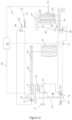
- Figure 2 shows in diagrammatic form the electronic and hydraulic elements of a drive system for elements of a forage harvester in accordance with the present invention.
- a prime mover 10 such as an internal combustion engine of the forage harvester is provided to drive various mechanical outputs, such as a first pulley 12, and hydraulic pumps 14, 16, 20, 30 by way of a transmission including an output gear 22 and a disengageable clutch 24 provided within a housing 25. Some of the outputs of the clutch 24 can be switched on or off during operation of the prime mover.
- a first hydraulic pump 16 and first pulley 12 are switched via the clutch 24, while other of the hydraulic pumps 14, 20, 30 are driven continuously.
- the chopper drum 4 is driven by a second pulley 26 fixed rotationally to the chopper drum 4.
- a drive belt 28 between the first pulley 12 and the second pulley 26 enables the chopper drum 4 to be driven by the prime mover while the clutch 24 is engaged.
- the chopper drum 4 has a large mass which together with the speed of rotation leads to a long run out of the chopper drum when the clutch 24 is disengaged, that is, in the absence of braking of the chopper drum it takes an undesirably long time for the chopper drum to come to rest.
- Typical run down times for an unbraked chopper drum are around 50 seconds.
- the rotating chopper drum presents a potential danger, for example, to an operator seeking to clear a blockage.
- a second hydraulic pump 14 is a swash plate variable displacement pump for closed circuits. Pump 14 is in communication with internal charge pump 30.
- First hydraulic pump 16 is a swash plate variable displacement pump for closed circuits without an additional charge pump.
- Charge pump 30 supplies both the first hydraulic pump 16 and the second variable displacement pump 14 with charge pressure.
- First hydraulic pump 16 is fed by a line 32 extending from charge pump 30 to the first hydraulic pump 16.
- the use of a single charge pump makes the use of a separate charge pump for the first hydraulic pump 16 superfluous, as is the need for the associated additional valve arrangements of such a construction.
- Lower and upper sets of feed rollers 34,36 are also driven by the hydraulic system.
- Variable displacement pump 14 conveys an oil flow, the quantity of which can be adjusted, to a bent axis displacement motor 38 which drives a lower roller gear set 44.
- a set of two lower feed rollers 36 are driven via a gear chain in the lower roller gear set 44.
- a cardan shaft 42 drives an upper roller gear set 40 which drives a set of two upper feed rollers 34 via a gear chain.
- the speed of the hydraulic motor 38 and the resulting speed of the upper and lower feed rollers 34,36 can be adjusted over a wide range by the combination of the second variable displacement pump 14 and the variable displacement motor 38.
- Such a good range of adjustability advantageously results in a large range of cutting length without the need for additional cutting length gear. Since the second variable displacement pump 14 is driven continuously, this enables the reversal of the direction of rotation of the feed rollers 34,36, even where the chopper drum 4 is clogged and so blocked from rotation.
- the first variable displacement pump 16 promotes an oil flow, the amount of which can be adjusted, to a bent axis constant motor 46 which is also used to drive a header gear 48 in turn driving the header via a cardan shaft 50. Since a relatively small speed spread of 1:3 is needed for the harvesting attachment 2, the hydraulic motor 46 can be designed as a constant motor.
- Both circuits can change the direction of rotation of the associated oil motors 38,46 by reversing the direction of the oil flow in the pumps 14,16 thus enabling the feed rollers 34,36 and the header to be reversed, for example to allow removal of blockages.
- a quick stop valve 52 is provided in the feed roller circuit. If a ferromagnetic body is drawn into the feed rollers, this is detected by a sensor 54. A reporting signal is sent to an electronic control unit 58, for example via a signal line 56. While a signal line 56 is illustrated it will be understood that this signal line (and the others referred to in this description) may take any suitable form and include a wireless communication route. On receipt of such a reporting signal the electronic control unit 58 issues a signal to actuate the quick stop valve 52, for example via a signal line 59. As a result of actuation of the quick stop valve 52 the feed motor 38 is stopped immediately and the associated stopping of the feed rollers 34,36 prevents the foreign body from reaching the chopper drum 4 and causing damage there. Such quick stop valves are known in the art (for example as disclosed in EP2557911 ) and will not be described further.
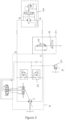
- a chopper drum brake valve 62 is arranged in the header circuit. Further details of the chopper drum brake valve 62 may be seen in FIG 3 .
- the oil flow of the first variable displacement pump 16 flows from port A ( FIG 3 ) via brake valve 62 to port A of the hydraulic motor 46 and so drives the hydraulic motor 46.
- the oil then flows along a return line from port B of the motor 46 to port B of the first variable displacement pump 16.
- Chopper drum brake valve 62 comprises a pilot-operated blocking valve 64 and a directional control valve 66.
- the pilot-operated blocking valve 64 is in an open position in both forward and reverse operation of the motor 46.
- the directional control valve 66 is a seat tight directional control valve, which is closed when in the denergised spring condition and open when energised. It can be seen that this construction of the chopper drum brake valve 62 omits the relief valve required in the construction of the chopper brake control circuit disclosed in WO 2011/128286 , resulting in a simpler, less expensive design. Further, since the chopper drum brake valve 62 is only connected to the one port of the motor 46, this arrangement is simpler and more cost effective to instal in the forage harvester than the arrangement disclosed in WO 2011/128286 .
- an instructing signal is provided to the electronic control unit 58 causing the electronic control unit 58 to send a suitable signal to cause the clutch 24 to be disengaged.
- the forage harvester is provided with a user input terminal within a cab of the forage harvester for the operator to use to cause such an instructing signal to be provided to the electronic control unit 58.
- the electronic control unit 58 On receipt of such an instructing signal, the electronic control unit 58 sends a suitable signal, for example via a signal line, to the directional control valve 66 to energise the directional control valve 66.
- a suitable signal for example via a signal line
- the directional control valve 66 When the directional control valve 66 is energised, the balance of forces on the ends of the piston causes the main piston part 64 to move from the open position to a closed position.
- the oil flow of the variable displacement pump 16 can no longer escape from port A and instead flows out through an internal high pressure relief valve 68 of the first variable displacement pump 16.
- the volumetric flow that flows via the high pressure relief valve 68 can be adjusted by adjusting the swivel angle of the first variable displacement pump 16.
- a high drive torque occurs on the pump shaft, which is transmitted from the pump shaft via the gear chain to the first pulley 12, the drive belt 28 and so to the chopper drum 4.
- the drive torque of the first variable displacement pump 16 acts as a brake for the chopper drum 4 and reduces the run out time of the chopper drum to around 6 or 7 seconds.
- the swash angle of the first variable displacement pump 16 can be set to a given design of chopper drum.
- chopper drums 4 include a number of chopping blades designed to interact with a shear bar to chop the harvested crop fed through the harvester. It is known to produce chopper drums having 20, 28 or 38 chopper blades about the circumference of the chopper drum. The weight and inertia of these different designs of chopper drum will differ from one another.
- the swash angle of first variable displacement pump 16 may be adjusted to ensure that the runout time of the chopper drum, whatever the design, is kept to around 6 or 7 seconds.
Landscapes
- Life Sciences & Earth Sciences (AREA)
- Environmental Sciences (AREA)
- Fluid-Pressure Circuits (AREA)
Abstract
A drive system for a forage harvester is disclosed. In a forage harvester having a prime mover (10), a chopper drum (4) driven from the prime mover (10) via a drive train, and feed rolls (34,36), the drive system comprises a clutch (24) operable between an engaged condition connecting the chopper drum (4) to the prime mover (10) and a disengaged position in which the chopper drum (4) is disconnected from the prime mover, a first hydraulic variable displacement pump (16) connected with the chopper drum (4) which pumps fluid around a first hydraulic circuit connected to a first motor (46), a second hydraulic variable displacement pump (14) which pumps fluid around a second hydraulic circuit to a feed roll motor (38) connected with the feed rolls (34,36) of the forage harvester. The drive system further comprises a single charge pump (30) hydraulically connected to both the first hydraulic variable displacement pump (16) and the second hydraulic variable displacement pump (14).
Description
- Not applicable.
- The present invention relates to an improved forage harvester, and, in particular, to a drive system for components of the forage harvester.
- In the absence of a suitable braking system, the large inertia and speed of rotation of a chopper drum within a forage harvester means it can often take 50 seconds or more for the chopper drum to cease rotation. This creates an undesirable danger and risk of injury to an operator of the forage harvester.
- A number of solutions to this problem have been proposed.
- In
WO 2011/128286 (AGCO International GmbH) a system is disclosed in which the chopper drum is driven from a prime mover of the forage harvester via a drive train, said braking system comprising a clutch operable between an engaged condition connecting the chopper drum to the prime mover and a disengaged position in which the chopper drum is disconnected from the prime mover. The hydraulic circuit includes a first pump connected with the chopper drum which pumps fluid around the hydraulic circuit, and a second pump connected with feed rolls of the forage harvester which feed crop to the chopper drum as well as a pilot-operated diverter valve/chopper drum brake valve. Both the first pump and the second pump require individual charge pumps to charge the first and second pumps. This adds complexity and cost to the hydraulic circuit. - Advantages of the present invention will be apparent from the description below.
- According to a first aspect of the present invention, in a drive system for a forage harvester, the forage harvester comprises a prime mover, a chopper drum driven from the prime mover via a drive train, and feed rolls, the drive system comprises a clutch operable between an engaged condition connecting the chopper drum to the prime mover and a disengaged position in which the chopper drum is disconnected from the prime mover, a first hydraulic variable displacement pump connected with the chopper drum which pumps fluid around a first hydraulic circuit connected to a first motor, a second hydraulic variable displacement pump which pumps fluid around a second hydraulic circuit to a feed roll motor connected with the feed rolls of the forage harvester, characterised in that the drive system further comprises a single charge pump hydraulically connected to both the first hydraulic variable displacement pump and the second hydraulic variable displacement pump.
- Preferably, when the clutch is operated to adopt the disengaged position and isolate the chopper drum from the prime mover, the drive system is operated to brake the chopper drum by operating a pilot-operated blocking valve in the first hydraulic circuit to disconnect fluid flow between the first pump and the first motor and divert flow through a high pressure relief valve located internally of the first hydraulic variable displacement pump.
- More preferably, the drive system further comprises an electronic controller operable to control operation of the clutch between the engaged and disengaged positions and to control operation of the pilot-operated blocking valve.
- Preferably, the feed roll motor is a continuously operated variable displacement motor.
- Preferably, the drive system further comprises a foreign object sensor and quick stop valve.
- Preferably, the drive system further comprises a set of lower roller gears operable by a supply of fluid from the second hydraulic variable displacement pump to the feed roll motor to drive a first lower set of feed rolls by a gear chain.
- Preferably, the drive system further comprises a set of upper roller gears operable by a supply of fluid from the second hydraulic variable displacement pump to the feed roll motor to drive a second upper set of feed rolls by a gear chain and a cardan shaft.
- Preferably, the drive system further comprises a chopper drum brake valve comprising a main piston part and a directional control valve.
- Within the scope of this application, it should be understood that the various aspects, embodiments, examples and alternatives set out herein, and individual features thereof may be taken independently or in any possible and compatible combination. Where features are described with reference to a single aspect or embodiment, it should be understood that such features are applicable to all aspects and embodiments unless otherwise stated or where such features are incompatible.
- The invention will now be described, by way of example only, with reference to the accompanying drawings, in which:
-
FIG 1 shows a schematic side view of a forage harvester; -
FIG 2 shows diagrammatically the electronic and hydraulic elements of a braking system for a forage harvester in accordance with the present invention; and -
FIG 3 shows diagrammatically a hydraulic supply circuit for use in the present invention. - The invention will now be described in the following detailed description with reference to the drawings, wherein preferred embodiments are described in detail to enable practice of the invention. Although the invention is described with reference to these specific preferred embodiments, it will be understood that the invention is not limited to these preferred embodiments. But to the contrary, the invention includes numerous alternatives, modifications and equivalents as will become apparent from consideration of the following detailed description.
-
Figure 1 shows a forage harvester provided with a front attachment 2 such as a header which contains cutting equipment for cutting and harvesting a crop. The cut crop is fed from the header via associatedfeed rollers chopper drum 4 where the crop is chopped into smaller pieces between thechopper drum 4 and an associatedshear bar 41. The chopped crop passes through a duct 5 and is optionally directed into acracker unit 6 where the crop is further crushed and threshed. The harvested crop is then blown upwards along the duct 5 by anaccelerator 8 and exits through a spout 9 directing the processed crop into a trailer or other vehicle moving alongside the forage harvester. -
Figure 2 shows in diagrammatic form the electronic and hydraulic elements of a drive system for elements of a forage harvester in accordance with the present invention. - A
prime mover 10 such as an internal combustion engine of the forage harvester is provided to drive various mechanical outputs, such as afirst pulley 12, andhydraulic pumps output gear 22 and adisengageable clutch 24 provided within ahousing 25. Some of the outputs of theclutch 24 can be switched on or off during operation of the prime mover. In the illustrated embodiment, a firsthydraulic pump 16 andfirst pulley 12 are switched via theclutch 24, while other of thehydraulic pumps - The
chopper drum 4 is driven by a second pulley 26 fixed rotationally to thechopper drum 4. Adrive belt 28 between thefirst pulley 12 and the second pulley 26 enables thechopper drum 4 to be driven by the prime mover while theclutch 24 is engaged. - As will be understood, the
chopper drum 4 has a large mass which together with the speed of rotation leads to a long run out of the chopper drum when theclutch 24 is disengaged, that is, in the absence of braking of the chopper drum it takes an undesirably long time for the chopper drum to come to rest. Typical run down times for an unbraked chopper drum are around 50 seconds. During this time, the rotating chopper drum presents a potential danger, for example, to an operator seeking to clear a blockage. - A second
hydraulic pump 14 is a swash plate variable displacement pump for closed circuits.Pump 14 is in communication withinternal charge pump 30. - First
hydraulic pump 16 is a swash plate variable displacement pump for closed circuits without an additional charge pump.Charge pump 30 supplies both the firsthydraulic pump 16 and the secondvariable displacement pump 14 with charge pressure. Firsthydraulic pump 16 is fed by aline 32 extending fromcharge pump 30 to the firsthydraulic pump 16. In comparison to the disclosed circuit ofWO 2011/128286 , the use of a single charge pump makes the use of a separate charge pump for the firsthydraulic pump 16 superfluous, as is the need for the associated additional valve arrangements of such a construction. - Lower and upper sets of
feed rollers Variable displacement pump 14 conveys an oil flow, the quantity of which can be adjusted, to a bentaxis displacement motor 38 which drives a lowerroller gear set 44. A set of twolower feed rollers 36 are driven via a gear chain in the lowerroller gear set 44. - A
cardan shaft 42 drives an upperroller gear set 40 which drives a set of twoupper feed rollers 34 via a gear chain. - The speed of the
hydraulic motor 38 and the resulting speed of the upper andlower feed rollers variable displacement pump 14 and thevariable displacement motor 38. Such a good range of adjustability advantageously results in a large range of cutting length without the need for additional cutting length gear. Since the secondvariable displacement pump 14 is driven continuously, this enables the reversal of the direction of rotation of thefeed rollers chopper drum 4 is clogged and so blocked from rotation. - The first
variable displacement pump 16 promotes an oil flow, the amount of which can be adjusted, to a bent axisconstant motor 46 which is also used to drive aheader gear 48 in turn driving the header via acardan shaft 50. Since a relatively small speed spread of 1:3 is needed for the harvesting attachment 2, thehydraulic motor 46 can be designed as a constant motor. - Both circuits (between
pump 16 andmotor 46 and betweenpump 14 and variable displacement motor 38) can change the direction of rotation of the associatedoil motors pumps feed rollers - A
quick stop valve 52 is provided in the feed roller circuit. If a ferromagnetic body is drawn into the feed rollers, this is detected by asensor 54. A reporting signal is sent to anelectronic control unit 58, for example via asignal line 56. While asignal line 56 is illustrated it will be understood that this signal line (and the others referred to in this description) may take any suitable form and include a wireless communication route. On receipt of such a reporting signal theelectronic control unit 58 issues a signal to actuate thequick stop valve 52, for example via a signal line 59. As a result of actuation of thequick stop valve 52 thefeed motor 38 is stopped immediately and the associated stopping of thefeed rollers chopper drum 4 and causing damage there. Such quick stop valves are known in the art (for example as disclosed inEP2557911 ) and will not be described further. - A chopper
drum brake valve 62 is arranged in the header circuit. Further details of the chopperdrum brake valve 62 may be seen inFIG 3 . In normal working operation, the oil flow of the firstvariable displacement pump 16 flows from port A (FIG 3 ) viabrake valve 62 to port A of thehydraulic motor 46 and so drives thehydraulic motor 46. The oil then flows along a return line from port B of themotor 46 to port B of the firstvariable displacement pump 16. - Chopper
drum brake valve 62 comprises a pilot-operatedblocking valve 64 and adirectional control valve 66. The pilot-operatedblocking valve 64 is in an open position in both forward and reverse operation of themotor 46. Thedirectional control valve 66 is a seat tight directional control valve, which is closed when in the denergised spring condition and open when energised. It can be seen that this construction of the chopperdrum brake valve 62 omits the relief valve required in the construction of the chopper brake control circuit disclosed inWO 2011/128286 , resulting in a simpler, less expensive design. Further, since the chopperdrum brake valve 62 is only connected to the one port of themotor 46, this arrangement is simpler and more cost effective to instal in the forage harvester than the arrangement disclosed inWO 2011/128286 . - If an operator wishes to interrupt operation of the
chopper drum 4, an instructing signal is provided to theelectronic control unit 58 causing theelectronic control unit 58 to send a suitable signal to cause the clutch 24 to be disengaged. Conveniently the forage harvester is provided with a user input terminal within a cab of the forage harvester for the operator to use to cause such an instructing signal to be provided to theelectronic control unit 58. - On receipt of such an instructing signal, the
electronic control unit 58 sends a suitable signal, for example via a signal line, to thedirectional control valve 66 to energise thedirectional control valve 66. When thedirectional control valve 66 is energised, the balance of forces on the ends of the piston causes themain piston part 64 to move from the open position to a closed position. - Once energised, the oil flow of the
variable displacement pump 16 can no longer escape from port A and instead flows out through an internal highpressure relief valve 68 of the firstvariable displacement pump 16. The volumetric flow that flows via the highpressure relief valve 68 can be adjusted by adjusting the swivel angle of the firstvariable displacement pump 16. In this operating situation, a high drive torque occurs on the pump shaft, which is transmitted from the pump shaft via the gear chain to thefirst pulley 12, thedrive belt 28 and so to thechopper drum 4. In this way, the drive torque of the firstvariable displacement pump 16 acts as a brake for thechopper drum 4 and reduces the run out time of the chopper drum to around 6 or 7 seconds. - The swash angle of the first
variable displacement pump 16 can be set to a given design of chopper drum. For example, as will be understood,chopper drums 4 include a number of chopping blades designed to interact with a shear bar to chop the harvested crop fed through the harvester. It is known to produce chopper drums having 20, 28 or 38 chopper blades about the circumference of the chopper drum. The weight and inertia of these different designs of chopper drum will differ from one another. The swash angle of firstvariable displacement pump 16 may be adjusted to ensure that the runout time of the chopper drum, whatever the design, is kept to around 6 or 7 seconds. - From reading the present disclosure, other modifications will be apparent to persons skilled in the art. Such modifications may involve other features which are already known in the field of forage harvesters and component parts therefore and which may be used instead of or in addition to features already described herein.
- From reading the present disclosure, other modifications will be apparent to persons skilled in the art. Such modifications may involve other features which are already known in the field of forage harvesters and component parts therefore and which may be used instead of or in addition to features already described herein.
Claims (8)
- A drive system for a forage harvester, the forage harvester comprising a prime mover (10), a chopper drum (4) driven from the prime mover (10) via a drive train, and feed rolls (34,36), the drive system comprising a clutch (24) operable between an engaged condition connecting the chopper drum (4) to the prime mover (10) and a disengaged position in which the chopper drum (4) is disconnected from the prime mover, a first hydraulic variable displacement pump (16) connected with the chopper drum (4) which pumps fluid around a first hydraulic circuit connected to a first motor (46), a second hydraulic variable displacement pump (14) which pumps fluid around a second hydraulic circuit to a feed roll motor (38) connected with the feed rolls (34,36) of the forage harvester, characterised in that the drive system further comprises a single charge pump (30) hydraulically connected to both the first hydraulic variable displacement pump (16) and the second hydraulic variable displacement pump (14).
- A drive system for a forage harvester according to claim 1, characterised in that when the clutch (24) is operated to adopt the disengaged position and isolate the chopper drum from the prime mover, the drive system is operated to brake the chopper drum (4) by operating a pilot-operated blocking valve (64) in the first hydraulic circuit to disconnect fluid flow between the first pump (16) and the first motor (46) and divert flow through a high pressure relief valve (68) located internally of the first hydraulic variable displacement pump (16).
- A drive system for a forage harvester according to claim 2, further comprising an electronic controller (58) operable to control operation of the clutch (24) between the engaged and disengaged positions and to control operation of the pilot-operated blocking valve (64).
- A drive system for a forage harvester according to any of claim 1 to claim 3, characterised in that the feed roll motor (38) is a continuously operated variable displacement motor.
- A drive system for a forage harvester according to any of claim 1 to claim 4, further comprising a foreign object sensor (54) and quick stop valve (52).
- A drive system for a forage harvester according to any of claim 1 to claim 5, further comprising a set of lower roller gears (44) operable by a supply of fluid from the second hydraulic variable displacement pump (14) to the feed roll motor (38) to drive a first lower set of feed rolls (36) by a gear chain.
- A drive system for a forage harvester according to any of claim 1 to claim 6, further comprising a set of upper roller gears (40) operable by a supply of fluid from the second hydraulic variable displacement pump (14) to the feed roll motor (38) to drive a second upper set of feed rolls (34) by a gear chain and a cardan shaft (42).
- A drive system for a forage harvester according to claim 2, further comprising a chopper drum brake valve (62) comprising a main piston part (64) and a directional control valve (66).
Applications Claiming Priority (1)
| Application Number | Priority Date | Filing Date | Title |
|---|---|---|---|
| GBGB2302457.3A GB202302457D0 (en) | 2023-02-21 | 2023-02-21 | Forage harvesters |
Publications (1)
| Publication Number | Publication Date |
|---|---|
| EP4420507A1 true EP4420507A1 (en) | 2024-08-28 |
Family
ID=85772369
Family Applications (1)
| Application Number | Title | Priority Date | Filing Date |
|---|---|---|---|
| EP24155715.6A Pending EP4420507A1 (en) | 2023-02-21 | 2024-02-05 | Forage harvesters |
Country Status (3)
| Country | Link |
|---|---|
| US (1) | US20240276917A1 (en) |
| EP (1) | EP4420507A1 (en) |
| GB (1) | GB202302457D0 (en) |
Citations (3)
| Publication number | Priority date | Publication date | Assignee | Title |
|---|---|---|---|---|
| EP2145527A2 (en) * | 2008-07-18 | 2010-01-20 | GKN Walterscheid GmbH | Drive assembly for an agricultural work machine |
| WO2011128286A1 (en) | 2010-04-15 | 2011-10-20 | Agco International Gmbh | Forage harvesters |
| WO2012099006A1 (en) * | 2011-01-20 | 2012-07-26 | ヤンマー株式会社 | Combine |
Family Cites Families (4)
| Publication number | Priority date | Publication date | Assignee | Title |
|---|---|---|---|---|
| US4073377A (en) * | 1976-04-20 | 1978-02-14 | Hesston Corporation | Feed rolls having automatic speed control |
| GB0005178D0 (en) * | 2000-03-06 | 2000-04-26 | Ford New Holland Nv | Feeder controls for a forage harvester |
| DE102009002849A1 (en) * | 2008-07-11 | 2010-01-14 | Deere & Company, Moline | Drive system for a feed conveyor of a harvester |
| US10492363B2 (en) * | 2015-11-20 | 2019-12-03 | Tribine Industries Llc | Rear grain cart handling assemblies for an articulated harvesting combine |
-
2023
- 2023-02-21 GB GBGB2302457.3A patent/GB202302457D0/en not_active Ceased
-
2024
- 2024-01-24 US US18/421,174 patent/US20240276917A1/en active Pending
- 2024-02-05 EP EP24155715.6A patent/EP4420507A1/en active Pending
Patent Citations (5)
| Publication number | Priority date | Publication date | Assignee | Title |
|---|---|---|---|---|
| EP2145527A2 (en) * | 2008-07-18 | 2010-01-20 | GKN Walterscheid GmbH | Drive assembly for an agricultural work machine |
| WO2011128286A1 (en) | 2010-04-15 | 2011-10-20 | Agco International Gmbh | Forage harvesters |
| EP2557911A1 (en) | 2010-04-15 | 2013-02-20 | AGCO International GmbH | Forage harvesters |
| US20130247527A1 (en) * | 2010-04-15 | 2013-09-26 | Agco International Gmbh | Forage Harvesters |
| WO2012099006A1 (en) * | 2011-01-20 | 2012-07-26 | ヤンマー株式会社 | Combine |
Also Published As
| Publication number | Publication date |
|---|---|
| US20240276917A1 (en) | 2024-08-22 |
| GB202302457D0 (en) | 2023-04-05 |
Similar Documents
| Publication | Publication Date | Title |
|---|---|---|
| RU2546859C2 (en) | Field forage harvester | |
| EP1261249B1 (en) | Feeder controls for a forage harvester | |
| US8869522B2 (en) | Drive system for an infeed conveyor of a harvester | |
| EP0986947B1 (en) | Reversing means for an agricultural harvesting machine | |
| US5778644A (en) | Crop harvesting platform having a reversible drive for the reel, cutterbar center-feed augers and conditioner rolls | |
| US6247296B1 (en) | Drive arrangement for the crop conveying and/or processing mechanism of a harvesting machine | |
| US7640718B2 (en) | Attachment for harvesting stalk-like goods where each cutting and conveying element is controlled individually | |
| US6494025B1 (en) | Device for remotely controlling a hydraulic system on a detachable implement | |
| EP1382889B1 (en) | Method of operation of a hydro-mechanical transmission with automatic braking capability. | |
| US9795081B2 (en) | Method for operating a combine harvester with belt drive configured to implement a measure to prevent slip of the belt drive and communicate the measure to an operator | |
| US6718746B2 (en) | Drive arrangement for ensilage harvester discharge spout | |
| EP0772385A1 (en) | Harvester with hydraulically driven, flow-compensated rotary cutter bed | |
| US7730701B1 (en) | Variable speed hydraulic conditioner drive | |
| US20240276917A1 (en) | Forage Harvesters | |
| US3945175A (en) | Variable speed feed roll drive mechanism for forage harvesters | |
| US9398744B2 (en) | Drive system for driving a chopper and feeder device of a harvesting machine | |
| JP3577738B2 (en) | Combine transmission mechanism | |
| JP5248725B2 (en) | Combine | |
| EP4656031A1 (en) | A forage harvester | |
| JP4301743B2 (en) | Hydraulic continuously variable transmission in a combine | |
| JP2002305942A (en) | Device for driving front treating part in combine harvester | |
| JP2004041115A (en) | Combine harvester | |
| JP2002291323A (en) | Culm transfer transmission apparatus of combine | |
| JP2002305943A (en) | System for driving front treating part in combine harvester |
Legal Events
| Date | Code | Title | Description |
|---|---|---|---|
| PUAI | Public reference made under article 153(3) epc to a published international application that has entered the european phase |
Free format text: ORIGINAL CODE: 0009012 |
|
| STAA | Information on the status of an ep patent application or granted ep patent |
Free format text: STATUS: THE APPLICATION HAS BEEN PUBLISHED |
|
| AK | Designated contracting states |
Kind code of ref document: A1 Designated state(s): AL AT BE BG CH CY CZ DE DK EE ES FI FR GB GR HR HU IE IS IT LI LT LU LV MC ME MK MT NL NO PL PT RO RS SE SI SK SM TR |
|
| STAA | Information on the status of an ep patent application or granted ep patent |
Free format text: STATUS: REQUEST FOR EXAMINATION WAS MADE |
|
| 17P | Request for examination filed |
Effective date: 20250228 |