EP4419008B1 - Method and apparatus for calibrating three-dimensional camera in x-ray imaging, and storage medium - Google Patents
Method and apparatus for calibrating three-dimensional camera in x-ray imaging, and storage medium Download PDFInfo
- Publication number
- EP4419008B1 EP4419008B1 EP22797261.9A EP22797261A EP4419008B1 EP 4419008 B1 EP4419008 B1 EP 4419008B1 EP 22797261 A EP22797261 A EP 22797261A EP 4419008 B1 EP4419008 B1 EP 4419008B1
- Authority
- EP
- European Patent Office
- Prior art keywords
- radiation field
- calibration plate
- distance
- center
- determining
- Prior art date
- Legal status (The legal status is an assumption and is not a legal conclusion. Google has not performed a legal analysis and makes no representation as to the accuracy of the status listed.)
- Active
Links
Images




Classifications
-
- G—PHYSICS
- G01—MEASURING; TESTING
- G01T—MEASUREMENT OF NUCLEAR OR X-RADIATION
- G01T7/00—Details of radiation-measuring instruments
- G01T7/005—Details of radiation-measuring instruments calibration techniques
-
- A—HUMAN NECESSITIES
- A61—MEDICAL OR VETERINARY SCIENCE; HYGIENE
- A61B—DIAGNOSIS; SURGERY; IDENTIFICATION
- A61B6/00—Apparatus or devices for radiation diagnosis; Apparatus or devices for radiation diagnosis combined with radiation therapy equipment
- A61B6/58—Testing, adjusting or calibrating thereof
-
- A—HUMAN NECESSITIES
- A61—MEDICAL OR VETERINARY SCIENCE; HYGIENE
- A61B—DIAGNOSIS; SURGERY; IDENTIFICATION
- A61B5/00—Measuring for diagnostic purposes; Identification of persons
- A61B5/0033—Features or image-related aspects of imaging apparatus, e.g. for MRI, optical tomography or impedance tomography apparatus; Arrangements of imaging apparatus in a room
- A61B5/0035—Features or image-related aspects of imaging apparatus, e.g. for MRI, optical tomography or impedance tomography apparatus; Arrangements of imaging apparatus in a room adapted for acquisition of images from more than one imaging mode, e.g. combining MRI and optical tomography
-
- A—HUMAN NECESSITIES
- A61—MEDICAL OR VETERINARY SCIENCE; HYGIENE
- A61B—DIAGNOSIS; SURGERY; IDENTIFICATION
- A61B5/00—Measuring for diagnostic purposes; Identification of persons
- A61B5/0059—Measuring for diagnostic purposes; Identification of persons using light, e.g. diagnosis by transillumination, diascopy, fluorescence
- A61B5/0077—Devices for viewing the surface of the body, e.g. camera, magnifying lens
-
- A—HUMAN NECESSITIES
- A61—MEDICAL OR VETERINARY SCIENCE; HYGIENE
- A61B—DIAGNOSIS; SURGERY; IDENTIFICATION
- A61B6/00—Apparatus or devices for radiation diagnosis; Apparatus or devices for radiation diagnosis combined with radiation therapy equipment
- A61B6/54—Control of apparatus or devices for radiation diagnosis
-
- A—HUMAN NECESSITIES
- A61—MEDICAL OR VETERINARY SCIENCE; HYGIENE
- A61B—DIAGNOSIS; SURGERY; IDENTIFICATION
- A61B6/00—Apparatus or devices for radiation diagnosis; Apparatus or devices for radiation diagnosis combined with radiation therapy equipment
- A61B6/58—Testing, adjusting or calibrating thereof
- A61B6/582—Calibration
-
- A—HUMAN NECESSITIES
- A61—MEDICAL OR VETERINARY SCIENCE; HYGIENE
- A61B—DIAGNOSIS; SURGERY; IDENTIFICATION
- A61B6/00—Apparatus or devices for radiation diagnosis; Apparatus or devices for radiation diagnosis combined with radiation therapy equipment
- A61B6/58—Testing, adjusting or calibrating thereof
- A61B6/582—Calibration
- A61B6/585—Calibration of detector units
-
- G—PHYSICS
- G01—MEASURING; TESTING
- G01B—MEASURING LENGTH, THICKNESS OR SIMILAR LINEAR DIMENSIONS; MEASURING ANGLES; MEASURING AREAS; MEASURING IRREGULARITIES OF SURFACES OR CONTOURS
- G01B21/00—Measuring arrangements or details thereof, where the measuring technique is not covered by the other groups of this subclass, unspecified or not relevant
- G01B21/02—Measuring arrangements or details thereof, where the measuring technique is not covered by the other groups of this subclass, unspecified or not relevant for measuring length, width, or thickness
- G01B21/04—Measuring arrangements or details thereof, where the measuring technique is not covered by the other groups of this subclass, unspecified or not relevant for measuring length, width, or thickness by measuring coordinates of points
- G01B21/042—Calibration or calibration artifacts
-
- G—PHYSICS
- G01—MEASURING; TESTING
- G01S—RADIO DIRECTION-FINDING; RADIO NAVIGATION; DETERMINING DISTANCE OR VELOCITY BY USE OF RADIO WAVES; LOCATING OR PRESENCE-DETECTING BY USE OF THE REFLECTION OR RERADIATION OF RADIO WAVES; ANALOGOUS ARRANGEMENTS USING OTHER WAVES
- G01S17/00—Systems using the reflection or reradiation of electromagnetic waves other than radio waves, e.g. lidar systems
- G01S17/88—Lidar systems specially adapted for specific applications
- G01S17/89—Lidar systems specially adapted for specific applications for mapping or imaging
- G01S17/894—Three-dimensional [3D] imaging with simultaneous measurement of time-of-flight at a two-dimensional [2D] array of receiver pixels, e.g. time-of-flight cameras or flash lidar
-
- G—PHYSICS
- G06—COMPUTING OR CALCULATING; COUNTING
- G06T—IMAGE DATA PROCESSING OR GENERATION, IN GENERAL
- G06T7/00—Image analysis
- G06T7/80—Analysis of captured images to determine intrinsic or extrinsic camera parameters, i.e. camera calibration
-
- H—ELECTRICITY
- H04—ELECTRIC COMMUNICATION TECHNIQUE
- H04N—PICTORIAL COMMUNICATION, e.g. TELEVISION
- H04N17/00—Diagnosis, testing or measuring for television systems or their details
- H04N17/002—Diagnosis, testing or measuring for television systems or their details for television cameras
-
- H—ELECTRICITY
- H04—ELECTRIC COMMUNICATION TECHNIQUE
- H04N—PICTORIAL COMMUNICATION, e.g. TELEVISION
- H04N23/00—Cameras or camera modules comprising electronic image sensors; Control thereof
- H04N23/30—Cameras or camera modules comprising electronic image sensors; Control thereof for generating image signals from X-rays
-
- A—HUMAN NECESSITIES
- A61—MEDICAL OR VETERINARY SCIENCE; HYGIENE
- A61B—DIAGNOSIS; SURGERY; IDENTIFICATION
- A61B2560/00—Constructional details of operational features of apparatus; Accessories for medical measuring apparatus
- A61B2560/02—Operational features
- A61B2560/0223—Operational features of calibration, e.g. protocols for calibrating sensors
-
- A—HUMAN NECESSITIES
- A61—MEDICAL OR VETERINARY SCIENCE; HYGIENE
- A61B—DIAGNOSIS; SURGERY; IDENTIFICATION
- A61B5/00—Measuring for diagnostic purposes; Identification of persons
- A61B5/103—Measuring devices for testing the shape, pattern, colour, size or movement of the body or parts thereof, for diagnostic purposes
- A61B5/107—Measuring physical dimensions, e.g. size of the entire body or parts thereof
- A61B5/1079—Measuring physical dimensions, e.g. size of the entire body or parts thereof using optical or photographic means
-
- A—HUMAN NECESSITIES
- A61—MEDICAL OR VETERINARY SCIENCE; HYGIENE
- A61B—DIAGNOSIS; SURGERY; IDENTIFICATION
- A61B6/00—Apparatus or devices for radiation diagnosis; Apparatus or devices for radiation diagnosis combined with radiation therapy equipment
-
- A—HUMAN NECESSITIES
- A61—MEDICAL OR VETERINARY SCIENCE; HYGIENE
- A61B—DIAGNOSIS; SURGERY; IDENTIFICATION
- A61B6/00—Apparatus or devices for radiation diagnosis; Apparatus or devices for radiation diagnosis combined with radiation therapy equipment
- A61B6/58—Testing, adjusting or calibrating thereof
- A61B6/589—Setting distance between source unit and patient
-
- G—PHYSICS
- G01—MEASURING; TESTING
- G01B—MEASURING LENGTH, THICKNESS OR SIMILAR LINEAR DIMENSIONS; MEASURING ANGLES; MEASURING AREAS; MEASURING IRREGULARITIES OF SURFACES OR CONTOURS
- G01B11/00—Measuring arrangements characterised by the use of optical techniques
- G01B11/24—Measuring arrangements characterised by the use of optical techniques for measuring contours or curvatures
- G01B11/245—Measuring arrangements characterised by the use of optical techniques for measuring contours or curvatures using a plurality of fixed, simultaneously operating transducers
-
- G—PHYSICS
- G01—MEASURING; TESTING
- G01B—MEASURING LENGTH, THICKNESS OR SIMILAR LINEAR DIMENSIONS; MEASURING ANGLES; MEASURING AREAS; MEASURING IRREGULARITIES OF SURFACES OR CONTOURS
- G01B15/00—Measuring arrangements characterised by the use of electromagnetic waves or particle radiation, e.g. by the use of microwaves, X-rays, gamma rays or electrons
-
- G—PHYSICS
- G06—COMPUTING OR CALCULATING; COUNTING
- G06T—IMAGE DATA PROCESSING OR GENERATION, IN GENERAL
- G06T2207/00—Indexing scheme for image analysis or image enhancement
- G06T2207/10—Image acquisition modality
- G06T2207/10116—X-ray image
-
- G—PHYSICS
- G06—COMPUTING OR CALCULATING; COUNTING
- G06T—IMAGE DATA PROCESSING OR GENERATION, IN GENERAL
- G06T2207/00—Indexing scheme for image analysis or image enhancement
- G06T2207/30—Subject of image; Context of image processing
- G06T2207/30244—Camera pose
Definitions
- the present disclosure relates to the technical field of medical imaging, in particular to a method and apparatus for calibrating a three-dimensional (3D) camera in X-ray imaging, and a storage medium.
- An X-ray imaging system generally includes an X-ray generation assembly, a Bucky-wall-stand (BWS) assembly, an examination table assembly, a film cassette assembly including a flat panel detector, a remote control host, etc.
- the X-ray generation assembly uses high voltage provided by a high voltage generator to emit X-rays that transmit through and radiate an imaging target, and forms medical image information of the imaging target on the flat panel detector.
- the flat panel detector transmits the medical image information to the control host.
- the imaging target can stand near the BWS assembly or lie on the examination table assembly, so as to undergo X-ray photography on different parts such as head, chest, abdomen, and joints, separately.
- US 2018/235566 A1 realtes to a method and a system for automatically aligning a positionable X-ray source of an X-ray system in alignment with a mobile X-ray detector where the X-ray system detects the position of the mobile X-ray detector using a 3D camera and then driving the positionable X-ray source to a position in alignment with the mobile X-ray detector.
- US 2017/100089 A1 relates to a method and apparatus for X-ray tube scanner automation using a 3D camera. An RGBD image of a patient on a patient table is received from a 3D camera mounted on an X-ray tube. A transformation between a coordinate system of the 3D camera and a coordinate system of the patient table is calculated.
- a patient model is estimated from the RGBD image of the patient.
- the X-ray tube is automatically controlled to acquire an X-ray image of a region of interest of the patient based on the patient model.
- EP 3 671 111 A1 relates to a method for calibrating a 3D camera that assists in applications in computed or digital radiography, wherein an accurate measurement of distances is required.
- the method is based on the measurement of the size of a reference object in the field-of-view of the visual part of the depth camera which is then matched to the distance measurements to said reference object by the depth measuring part of the depth camera.
- the method may be applied for the determination of the distance between an X-ray source and an image detector.
- 3D cameras are widely applied in X-ray imaging systems to implement various measurement-related functions (e.g., virtual collimation). Positioning information in a 3D photo taken by a 3D camera is usually based on a 3D camera coordinate system, while many parameters in an X-ray imaging application are based on an X-ray tube coordinate system, such that if the positioning information determined on the basis of the 3D photo is directly applied to the X-ray imaging application, a system error may be caused.
- Embodiments of the present disclosure provide a method and apparatus for calibrating a 3D camera in X-ray imaging, and a storage medium.
- a method for calibrating a 3D camera in X-ray imaging including:
- the transformation matrix is determined on the basis of a transformation relationship between 3D coordinates of the positioning marker in the calibration plate in the X-ray tube coordinate system and 3D coordinates of the positioning marker in the 3D camera coordinate system, so as to implement calibration of the 3D camera and eliminate the system error caused by the coordinate system difference.
- the center of the calibration plate does not coincide with the radiation field center of the X-ray tube; the calibration plate is disposed in an XY plane including an X axis and a Y axis; and the method further includes: moving the calibration plate within the XY plane until the center of the calibration plate coincides with the radiation field center of the X-ray tube.
- the calibration plate is moved to make the center of the calibration plate coincide with the radiation field center of the X-ray tube.
- 3D coordinates of the center of the calibration plate in the X-ray tube coordinate system can be simplified, and thus a computation process of the transformation matrix is simplified.
- the determining second 3D coordinates of the positioning marker in an X-ray tube coordinate system on the basis of the distance includes:
- the center of the calibration plate does not coincide with the radiation field center of the X-ray tube; the calibration plate is disposed in an XY plane including an X axis and a Y axis; and the determining second 3D coordinates of the positioning marker in an X-ray tube coordinate system on the basis of the distance includes: determining 3D coordinates ( ⁇ x, ⁇ y , h ) of the center of the calibration plate in the X-ray tube coordinate system, where h represents the distance, ⁇ x represents a component of a distance vector between the radiation field center and the center of the calibration plate on the X axis, and ⁇ y represents a component of the distance vector between the radiation field center and the center of the calibration plate on the Y axis; determining a distance vector T between the positioning marker and the center of the calibration plate; determining a component x of the distance vector T on the X axis and a component y of the distance vector T on the Y axis; and determining the second 3D coordinates
- the width and height of a radiation field can also be calibrated to eliminate the system error caused by the radiation field difference.
- the determining a set radiation field range and an actual radiation field range on the calibration plate corresponding to the set radiation field range includes:
- the set radiation field range and the actual radiation field range can be determined in many ways to adapt to various implementation environments.
- the method further includes:
- the transformation matrix is determined using multiple distance adjustments, such that the accuracy is improved.
- An apparatus for calibrating a 3D camera in X-ray imaging including:
- the transformation matrix is determined on the basis of a transformation relationship between 3D coordinates of the positioning marker in the calibration plate in the X-ray tube coordinate system and 3D coordinates of the positioning marker in the 3D camera coordinate system, so as to implement calibration of the 3D camera and eliminate the system error caused by the coordinate system difference.
- the center of the calibration plate does not coincide with the radiation field center of the X-ray tube; the calibration plate is disposed in an XY plane including an X axis and a Y axis; and the acquiring module is further configured to move the calibration plate within the XY plane until the center of the calibration plate coincides with the radiation field center of the X-ray tube.
- the calibration plate is moved to make the center of the calibration plate coincide with the radiation field center of the X-ray tube.
- 3D coordinates of the center of the calibration plate in the X-ray tube coordinate system can be simplified, and thus a computation process of the transformation matrix is simplified.
- the second determining module is configured to: determine 3D coordinates (0, 0, h ) of the center of the calibration plate in the X-ray tube coordinate system, where h represents the distance; determine a distance vector T between the positioning marker and the center of the calibration plate; determine a component x of the distance vector T on the X axis and a component y of the distance vector T on the Y axis; and determine the second 3D coordinates ( x, y, h ) .
- the center of the calibration plate does not coincide with the radiation field center of the X-ray tube; the calibration plate is disposed in an XY plane including an X axis and a Y axis; and the second determining module is configured to: determine 3D coordinates ( ⁇ x , ⁇ y , h ) of the center of the calibration plate in the X-ray tube coordinate system, where h represents the distance, ⁇ x represents a component of a distance vector between the radiation field center and the center of the calibration plate on the X axis, and ⁇ y represents a component of the distance vector between the radiation field center and the center of the calibration plate on the Y axis; determine a distance vector T between the positioning marker and the center of the calibration plate; determine a component x of the distance vector T on the X axis and a component y of the distance vector T on the Y axis; and determine the second 3D coordinates ( ⁇ x+x, ⁇ y+y, h ) of the positioning
- a fourth determining module configured to determine a set radiation field range and an actual radiation field range on the calibration plate corresponding to the set radiation field range; and determine a radiation field width calibration parameter ⁇ w and a radiation field height calibration parameter ⁇ h , where
- the width and height of a radiation field can also be calibrated to eliminate the system error caused by the radiation field difference.
- the fourth determining module is configured to: determine the actual radiation field range on the basis of a user input; and make an adjustment to obtain the set radiation field range corresponding to the actual radiation field range; or, determine the set radiation field range on the basis of a user input; and measure the actual radiation field range corresponding to the set radiation field range on the calibration plate.
- the set radiation field range and the actual radiation field range can be determined in many ways to adapt to various implementation environments.
- the transformation matrix is determined using multiple distance adjustments, such that the accuracy is improved.
- An apparatus for calibrating a 3D camera in X-ray imaging including a processor and a memory, where the memory stores an application executable by the processor and configured to enable the processor to execute the method for calibrating a 3D camera in X-ray imaging according to any one of the foregoing embodiments.
- the embodiments of the present disclosure provide the 3D camera calibration apparatus having a processor-memory architecture.
- the transformation matrix is determined on the basis of a transformation relationship between 3D coordinates of the positioning marker in the calibration plate in the X-ray tube coordinate system and 3D coordinates of the positioning marker in the 3D camera coordinate system, so as to implement calibration of the 3D camera and eliminate the system error caused by the coordinate system difference.
- a computer-readable storage medium having computer-readable instructions stored thereon, where the computer-readable instructions are used for implementing the method for calibrating a 3D camera in X-ray imaging according to any one of the foregoing embodiments.
- the embodiments of the present disclosure provide the computer-readable storage medium including the computer-readable instructions.
- the transformation matrix is determined on the basis of a transformation relationship between 3D coordinates of the positioning marker in the calibration plate in the X-ray tube coordinate system and 3D coordinates of the positioning marker in the 3D camera coordinate system, so as to implement calibration of the 3D camera and eliminate the system error caused by the coordinate system difference.
- Reference numerals are as follows: Numerals Meanings 100 A method for calibrating a 3D camera in X-ray imaging 101-104 Steps 60 Control host 70 Ceiling 71 X-ray tube 72 Collimator 73 X-ray source 81 3D camera 20 Ground 30 Calibration plate 300 Calibration plate 301-304 Circles 400 Calibration plate 401-404 Concentric circles 500 An apparatus for calibrating a 3D camera in X-ray imaging 501 Acquiring module 502 First determining module 502 Second determining module 503 Third determining module 504 Fourth determining module 600 An apparatus for calibrating a 3D camera in X-ray imaging 601 Processor 602 Memory
- positioning information in a 3D photo taken by a 3D camera is usually based on a 3D camera coordinate system, while many parameters in an X-ray imaging application are based on an X-ray tube coordinate system, such that if the positioning information in the 3D photo is directly applied to the X-ray imaging application, a system error may be caused by the coordinate system difference.
- the 3D camera is calibrated on the basis of the transformation matrix, so as to eliminate the system error caused by the coordinate system difference.
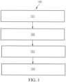
- FIG. 1 is a flowchart of a method for calibrating a 3D camera in X-ray imaging according to embodiments of the present disclosure.
- the method shown in FIG. 1 can be executed by a controller.
- the controller can be implemented as or integrated to a control host of an X-ray imaging system, and can also be implemented as a control unit independent of the control host.
- the method 100 includes the following steps: Step 101: Acquire a 3D image of a calibration plate captured by a 3D camera, where the calibration plate includes a positioning marker, and the calibration plate has a predetermined distance from an X-ray tube.
- the 3D camera is usually fixed onto a tube casing of the X-ray tube in an X-ray generation assembly, or fixed onto a collimator shell in the X-ray generation assembly.
- a recess for accommodating the 3D camera is formed on the tube casing or the collimator shell, and the 3D camera is fixed into the recess through bolt connection, snap-fit connection, a steel wire loop, etc.
- the calibration plate is configured to calibrate the 3D camera.
- the positioning marker for assisting positioning is disposed on the calibration plate, and one or more positioning markers, preferably more than one positioning markers, may be provided.
- the positioning markers may be a plurality of circles, where the distance between every two adjacent circles is the same.
- the positioning markers may be a plurality of concentric circles, where the radius difference between adjacent concentric circles is the same.
- the calibration plate is disposed on the ground, the X-ray tube (not rotated) is aligned with the calibration plate on the ground, and the ray direction of the X-ray tube is perpendicular to the ground.
- the distance between the calibration plate and the X-ray tube is the vertical height from an X-ray source in the X-ray tube to the calibration plate.
- the calibration plate is disposed on the wall, an opening of the X-ray tube (not rotated) is aligned with the calibration plate on the wall, and then the ray direction of the X-ray tube is perpendicular to the wall.
- the distance between the calibration plate and the X-ray tube is the horizontal distance from an X-ray source in the X-ray tube to the calibration plate.
- Step 102 Determine first 3D coordinates of the positioning marker in a 3D camera coordinate system on the basis of the 3D image.
- the 3D camera coordinate system is a 3D rectangular coordinate system established with the focus center of the 3D camera as the origin and the optical axis as a Z axis.
- the origin is the focus center (i.e., the optical center) of the 3D camera;
- an X axis in the 3D camera coordinate system is parallel to an X axis in an image plane;
- a Y axis in the 3D camera coordinate system is parallel to a Y axis in the image plane;
- a Z axis in the 3D camera coordinate system is a camera optical axis, where the Z axis is perpendicular to the image plane.
- the image plane is a two-dimensional rectangular coordinate system.
- step 102 specifically includes: transforming the 3D image acquired in step 101 to a two-dimensional image, determining, from the two-dimensional image, two-dimensional coordinates of the positioning marker in an image coordinate system by using an image recognition algorithm, and then transforming the two-dimensional coordinates of the positioning marker in the image coordinate system to 3D coordinates (i.e., the first 3D coordinates) of the positioning marker in the 3D camera coordinate system on the basis of depth of field parameters of the 3D camera.
- 3D coordinates i.e., the first 3D coordinates
- step 102 specifically includes: determining 3D coordinates (i.e., the first 3D coordinates) of the positioning marker in the 3D image in the 3D camera coordinate system on the basis of a 3D positioning algorithm.
- Step 103 Determine second 3D coordinates of the positioning marker in an X-ray tube coordinate system on the basis of the distance.
- the X-ray tube coordinate system is a 3D rectangular coordinate system established with the X-ray source as the origin and the X-ray axis as a Z axis.
- the origin is the X-ray source
- an X axis in the X-ray tube coordinate system is parallel to the X axis in the image plane
- a Y axis in the X-ray tube coordinate system is parallel to the Y axis in the image plane
- a Z axis in the 3D camera coordinate system is the X-ray axis, where the Z axis is usually perpendicular to the calibration plate.
- the center of the calibration plate does not coincide with the radiation field center of the X-ray tube; the calibration plate is disposed in an XY plane including an X axis and a Y axis; and the method further includes: moving the calibration plate within the XY plane until the center of the calibration plate coincides with the radiation field center of the X-ray tube.
- the radiation field center of the X-ray tube usually forms an imaging marker (e.g., a laser crosshair) on an imaging target.
- an imaging marker e.g., a laser crosshair
- the calibration plate is moved manually or automatically within the XY plane where the calibration plate is disposed, until the center of the calibration plate coincides with the radiation field center of the X-ray tube.
- the calibration plate is moved manually or automatically within the XY plane where the calibration plate is disposed, until the center of the calibration plate coincides with the radiation field center of the X-ray tube.
- the 3D coordinates of the center of the calibration plate in the X-ray tube coordinate system can be simplified, and thus the subsequent computation process is simplified.
- the determining second 3D coordinates of the positioning marker in the X-ray tube coordinate system on the basis of the distance in step 103 includes: (1) determining 3D coordinates (0, 0, h ) of the center of the calibration plate in the X-ray tube coordinate system, where h represents the distance; (2) determining a distance vector T between the positioning marker and the center of the calibration plate; (3) determining a component x of the distance vector T on the X axis and a component y of the distance vector T on the Y axis; and (4) determining the second 3D coordinates ( x, y, h ) .
- the center of the calibration plate does not coincide with the radiation field center of the X-ray tube; the calibration plate is disposed in an XY plane including an X axis and a Y axis; and the determining second 3D coordinates of the positioning marker in an X-ray tube coordinate system on the basis of the distance in step 103 includes:
- Step 104 Determine, on the basis of the first 3D coordinates and the second 3D coordinates, a transformation matrix adapted to calibrate the 3D camera.
- the transformation matrix for calibrating the 3D camera can be computed on the basis of a matrix method.
- the number of the first 3D coordinates is preferably greater than 6; correspondingly, the number of the second 3D coordinates is preferably greater than 6.
- the distance between the calibration plate and the X-ray tube can be adjusted multiples times, and the first 3D coordinates and the second 3D coordinates after each distance adjustment are determined, accordingly. Then, the transformation matrix is computed more accurately by using the first 3D coordinates and the second 3D coordinates determined after multiple distance adjustments.
- the number of the first 3D coordinates determined after multiple distance adjustments is preferably greater than 6; correspondingly, the number of the second 3D coordinates determined after multiple adjustments is preferably greater than 6.
- the transformation matrix is determined using multiple distance adjustments, such that the accuracy is improved.
- the distance is adjusted m times, and the first 3D coordinates and the second 3D coordinates after distance adjustment are determined.
- Method (1) three corresponding 3D coordinate pairs are selected from first 3D coordinates before the distance adjustments and second 3D coordinates before the distance adjustments, then three corresponding 3D coordinate pairs are selected from first 3D coordinates after the first distance adjustment and second 3D coordinates after the first distance adjustment, and the transformation matrix is computed by using the six 3D coordinate pairs.
- Method (2) three corresponding 3D coordinate pairs are selected from first 3D coordinates before the distance adjustments and second 3D coordinates before the distance adjustments, then three corresponding 3D coordinate pairs are selected from first 3D coordinates after the first distance adjustment and second 3D coordinates after the first distance adjustment, and the transformation matrix is computed by using the six 3D coordinate pairs.
- Method (3) three corresponding 3D coordinate pairs are selected from first 3D coordinates after the first distance adjustment and second 3D coordinates after the first distance adjustment, then three corresponding 3D coordinate pairs are selected from first 3D coordinates after the second distance adjustment and second 3D coordinates after the second distance adjustment, and the transformation matrix is computed by using the six 3D coordinate pairs.
- the transformation matrix is determined on the basis of a transformation relationship between 3D coordinates of the positioning marker in the calibration plate in the X-ray tube coordinate system and 3D coordinates of the positioning marker in the 3D camera coordinate system, so as to implement calibration of the 3D camera and eliminate the system error caused by the coordinate system difference.
- the radiation field width calibration parameter ⁇ w and the radiation field height calibration parameter ⁇ h reflect the difference between actual and set collimator radiation fields, can be used for calibrating the system error, and can also be used for calibrating the radiation field of a virtual collimator to make the radiation field of the virtual collimator consistent with the radiation field of a real collimator. Hence, the width and height of a radiation field can also be calibrated to make the actual radiation field range consistent with the set radiation field range.
- the determining a set radiation field range and an actual radiation field range on the calibration plate corresponding to the set radiation field range includes the following methods: Method (1): determining the actual radiation field range on the basis of a user input; and making an adjustment to obtain the set radiation field range corresponding to the actual radiation field range.
- the actual radiation field range inputted by a user is 10 ⁇ 10 cm 2 .
- a set radiation field range in an X-ray imaging system is adjusted until it is found by manually observing the calibration plate or performing image recognition on a 3D picture of the calibration plate that the actual radiation field range on the calibration plate is 10 ⁇ 10 cm 2 , and at that time, the set radiation field range, assumed as 11 ⁇ 11 cm 2 , in the X-ray imaging system is recorded and then considered as the set radiation field range.
- the actual radiation field range is 10 ⁇ 10 cm 2
- the set radiation field range corresponding to the 10 ⁇ 10 cm 2 actual radiation field range is 11 ⁇ 11 cm 2 .
- Method (2) determining the set radiation field range on the basis of a user input; and measuring the actual radiation field range corresponding to the set radiation field range. Therefore, the set radiation field range and the actual radiation field range can be determined in many ways to adapt to various implementation environments.
- the set radiation field range in the X-ray imaging system inputted by the user is 10 ⁇ 10 cm 2 ; then, it is found by manually observing the calibration plate or performing image recognition on the 3D picture of the calibration plate that the actual radiation field range on the calibration plate is 9 ⁇ 9 cm 2 Therefore, it is determined that the actual radiation field range is 9 ⁇ 9 cm 2 , and the set radiation field range corresponding to the 9 ⁇ 9 cm 2 actual radiation field range is 10 ⁇ 10 cm 2 .
- FIG. 2 is a schematic diagram of 3D camera calibration in X-ray imaging according to embodiments of the present disclosure.
- an X-ray generation assembly including an X-ray tube 71 and a collimator 72 is connected to a telescopic sleeve 79 using a support, and the telescopic sleeve 79 is connected to a ceiling 70.
- a 3D camera 81 is disposed on a shell of the collimator 72.
- a control host 60 may be a control host disposed in a local control room, and may also be a remote control host, such as a control host at the cloud.
- a calibration plate 30 for calibrating the 3D camera 81 is disposed on the ground 20.
- a positioning marker for assisting positioning is disposed on the calibration plate 30, and one or more positioning markers may be provided.
- the X-ray tube 71 is aligned with the calibration plate 30 on the ground, and the ray direction of the X-ray tube 71 is perpendicular to the calibration plate 30.
- the distance between the calibration plate 30 and the X-ray tube 71 is the vertical height from an X-ray source 73 in the X-ray tube 71 to the calibration plate 30.
- FIG. 3 is the first schematic diagram of determining 3D coordinates of the center of a calibration plate in an X-ray tube coordinate system according to embodiments of the present disclosure.
- a calibration plate 300 has a plurality of circles serving as positioning markers, which is exemplified with 28 circles in the embodiment shown in FIG. 3 .
- the 28 circles cover 7 rows, and each row cover 4 circles.
- the circles in each row are equidistantly spaced and the spacing is a known fixed value D; moreover, the spacing between adjacent circles in different rows is also D.
- the first circle from the left of the first row and the second circle from the left of the first row are adjacent to each other within the same row, and the spacing is D;
- the second circle from the left of the first row and the third circle from the left of the first row are adjacent to each other within the same row, and the spacing is D;
- the first circle from the left of the first row and the first circle from the left of the second row are adjacent to each other in different rows, and the spacing is D;
- the first circle from the left of the first row and the second circle from the left of the second row are adjacent to each other in different rows, and the spacing is D.
- the distance between any two adjacent circles is the known fixed value D.
- the center of the calibration plate 300 is taken as point O.
- the radiation field center of an X-ray tube presented on the calibration plate 300 is point M.
- 3D coordinates of each circle in a 3D camera coordinate system can be obtained through a 3D picture of the calibration plate 300.
- 3D coordinates of each circle in an X-ray tube coordinate system can be determined, accordingly, so as to facilitate computing a transformation matrix of a 3D camera.
- the method for determining the 3D coordinates of each circle in the X-ray tube coordinate system includes: case (1): in a case that it is observed that point M and point O on the calibration plate coincide, it can be determined that the 3D coordinates of the center of the plate in the X-ray tube coordinate system are (0, 0, h), and then the 3D coordinates of each circle in the X-ray tube coordinate system can be conveniently determined.
- the coordinates of the center point O of the calibration plate in the X-ray tube coordinate system can be calibrated as (0, 0, 180).
- the coordinates of the first circle 301 on the left of the center point O in the X-ray tube coordinate system are (5, 0, 180); the coordinates of the first circle 302 on the right of the center point O in the X-ray tube coordinate system are (-5, 0, 180); the coordinates of the first circle 303 above the center point O in the X-ray tube coordinate system are (0, 5, 180), and the coordinates of the first circle 304 below the center point O in the X-ray tube coordinate system are (0, -5, 180).
- the coordinates of all the circles in the X-ray tube coordinate system can be determined.
- Case (2) in a case that point M and point O on the calibration plate 300 do not coincide as shown in FIG. 3 , a distance vector between the radiation field center (i.e., point M) and the center of the calibration plate (i.e., point O) is S.
- a component of the distance vector S on an X axis is ⁇ x
- a component of the distance vector S on a Y axis is ⁇ y .
- the modulus of ⁇ x is D
- the modulus of ⁇ y is D.
- the 3D coordinates ( ⁇ x, ⁇ y, h ) of the center of the calibration plate in the X-ray tube coordinate system can be determined, where h represents the distance between the calibration plate 300 and the X-ray source of the X-ray tube.
- a distance vector T between each circle and the center of the calibration plate can be determined, a component x of the distance vector T on the X axis and a component y of the distance vector T on the Y axis are determined, and thus the 3D coordinates ( ⁇ x+x, ⁇ y+y, h ) of each circle in the X-ray tube coordinate system are determined.
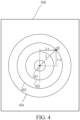
- FIG. 4 is the second schematic diagram of determining 3D coordinates of the center of a calibration plate in an X-ray tube coordinate system according to embodiments of the present disclosure.
- a calibration plate 400 includes positioning markers implemented as a concentric circle 401, a concentric circle 402, a concentric circle 403, a concentric circle 404, and a concentric circle 405.
- the radius of the concentric circle 401 is r ; the radius difference between adjacent concentric circles is the same, and it is assumed that the radius difference is d.
- the center of the calibration plate 400 is taken as point O.
- the radiation field center of an X-ray tube presented on the calibration plate 400 is point M.
- 3D coordinates of a quadrant point (e.g., an upper quadrant point, a lower quadrant point, a left quadrant point, and a right quadrant point) of each concentric circle in a 3D camera coordinate system can be obtained through a D picture of the calibration plate 400.
- 3D coordinates of a quadrant point of each concentric circle in an X-ray tube coordinate system can be determined, accordingly, so as to facilitate computing a transformation matrix of a 3D camera.
- the method for determining the 3D coordinates of the quadrant point of each concentric circle in the X-ray tube coordinate system includes:
- FIG. 5 is a structural diagram of an apparatus for calibrating a 3D camera in X-ray imaging according to embodiments of the present disclosure.
- an apparatus 500 for calibrating a 3D camera in X-ray imaging includes:
- the center of the calibration plate does not coincide with the radiation field center of the X-ray tube; the calibration plate is disposed in an XY plane including an X axis and a Y axis; and the acquiring module is further configured to move the calibration plate within the XY plane until the center of the calibration plate coincides with the radiation field center of the X-ray tube.
- the second determining module 503 is configured to: determine 3D coordinates (0, 0, h ) of the center of the calibration plate in the X-ray tube coordinate system, where h represents the distance; determine a distance vector T between the positioning marker and the center of the calibration plate; determine a component x of the distance vector T on the X axis and a component y of the distance vector T on the Y axis; and determine the second 3D coordinates ( x, y, h ) .
- the center of the calibration plate does not coincide with the radiation field center of the X-ray tube; the calibration plate is disposed in an XY plane including an X axis and a Y axis; and the second determining module 503 is configured to: determine 3D coordinates ( ⁇ x , ⁇ y, h ) of the center of the calibration plate in the X-ray tube coordinate system, where h represents the distance, ⁇ x represents a component of a distance vector between the radiation field center and the center of the calibration plate on the X axis, and ⁇ y represents a component of the distance vector between the radiation field center and the center of the calibration plate on the Y axis; determine a distance vector T between the positioning marker and the center of the calibration plate; determine a component x of the distance vector T on the X axis and a component y of the distance vector T on the Y axis; and determine the second 3D coordinates ( ⁇ x+x, ⁇ y+y, h ) of the
- a fourth determining module 505 configured to determine a set radiation field range and an actual radiation field range on the calibration plate corresponding to the set radiation field range; and determine a radiation field width calibration parameter ⁇ w and a radiation field height calibration parameter ⁇ h
- the fourth determining module 505 is configured to: determine the actual radiation field range on the basis of a user input; and make an adjustment to obtain the set radiation field range corresponding to the actual radiation field range; or, determine the set radiation field range on the basis of a user input; and measure the actual radiation field range corresponding to the set radiation field range on the calibration plate.
- Embodiments of the present disclosure further provide an apparatus for calibrating a 3D camera in X-ray imaging having a processor-memory architecture.
- FIG. 6 is a structural diagram of an apparatus for calibrating a 3D camera in X-ray imaging having a processor-memory architecture according to embodiments of the present disclosure.
- an apparatus 600 in which an industrial edge application is deployed includes a processor 601, a memory 602, and a computer program stored on the memory 602 and capable of running on the processor 601, where when executed by the processor 601, the computer program implements the method for calibrating a 3D camera in X-ray imaging according to any one of the foregoing embodiments.
- the memory 602 may be specifically implemented as various storage media such as an electrically-erasable programmable read-only memory (EEPROM), a flash memory, and a programmable read-only memory (PROM).
- the processor 601 may be implemented to include one or more central processing units (CPUs) or one or more field-programmable gate arrays, where the field-programmable gate arrays integrate one or more CPU cores.
- the CPU or the CPU core may be implemented as a CPU or an MCU or a DSP or the like.
- Hardware modules in the embodiments can be implemented mechanically or electronically.
- a hardware module may include a dedicated permanent circuit or logic device (e.g., a dedicated processor, an FPGA or an ASIC) to complete a corresponding operation.
- a hardware module may also include a programmable logic device or circuit temporarily configured by software (e.g., including a general-purpose processor or other programmable processors) to execute a corresponding operation.
- a dedicated permanent circuit or a temporarily configured circuit (configured by software) may be used to implement a hardware module, which can be determined based on costs and time considerations.
Landscapes
- Health & Medical Sciences (AREA)
- Life Sciences & Earth Sciences (AREA)
- Engineering & Computer Science (AREA)
- Physics & Mathematics (AREA)
- Medical Informatics (AREA)
- Molecular Biology (AREA)
- Biomedical Technology (AREA)
- General Health & Medical Sciences (AREA)
- Pathology (AREA)
- Nuclear Medicine, Radiotherapy & Molecular Imaging (AREA)
- Veterinary Medicine (AREA)
- Public Health (AREA)
- Animal Behavior & Ethology (AREA)
- Surgery (AREA)
- Heart & Thoracic Surgery (AREA)
- Biophysics (AREA)
- High Energy & Nuclear Physics (AREA)
- Radiology & Medical Imaging (AREA)
- Optics & Photonics (AREA)
- General Physics & Mathematics (AREA)
- Multimedia (AREA)
- Signal Processing (AREA)
- Spectroscopy & Molecular Physics (AREA)
- Electromagnetism (AREA)
- Theoretical Computer Science (AREA)
- Computer Vision & Pattern Recognition (AREA)
- Computer Networks & Wireless Communication (AREA)
- Remote Sensing (AREA)
- Radar, Positioning & Navigation (AREA)
- Apparatus For Radiation Diagnosis (AREA)
- Length-Measuring Devices Using Wave Or Particle Radiation (AREA)
Description
- The present disclosure relates to the technical field of medical imaging, in particular to a method and apparatus for calibrating a three-dimensional (3D) camera in X-ray imaging, and a storage medium.
- An X-ray imaging system generally includes an X-ray generation assembly, a Bucky-wall-stand (BWS) assembly, an examination table assembly, a film cassette assembly including a flat panel detector, a remote control host, etc. The X-ray generation assembly uses high voltage provided by a high voltage generator to emit X-rays that transmit through and radiate an imaging target, and forms medical image information of the imaging target on the flat panel detector. The flat panel detector transmits the medical image information to the control host. The imaging target can stand near the BWS assembly or lie on the examination table assembly, so as to undergo X-ray photography on different parts such as head, chest, abdomen, and joints, separately.
US 2018/235566 A1 realtes to a method and a system for automatically aligning a positionable X-ray source of an X-ray system in alignment with a mobile X-ray detector where the X-ray system detects the position of the mobile X-ray detector using a 3D camera and then driving the positionable X-ray source to a position in alignment with the mobile X-ray detector.
US 2017/100089 A1 relates to a method and apparatus for X-ray tube scanner automation using a 3D camera. An RGBD image of a patient on a patient table is received from a 3D camera mounted on an X-ray tube. A transformation between a coordinate system of the 3D camera and a coordinate system of the patient table is calculated. A patient model is estimated from the RGBD image of the patient. The X-ray tube is automatically controlled to acquire an X-ray image of a region of interest of the patient based on the patient model.
EP 3 671 111 A1 relates to a method for calibrating a 3D camera that assists in applications in computed or digital radiography, wherein an accurate measurement of distances is required. The method is based on the measurement of the size of a reference object in the field-of-view of the visual part of the depth camera which is then matched to the distance measurements to said reference object by the depth measuring part of the depth camera. The method may be applied for the determination of the distance between an X-ray source and an image detector.
Li Jing et al.: "A fully automatic surgical registration method for percutaneous abdominal puncture surgical navigation", Computer in Biology and Medicine, vol. 136, July 29, 2021 discloses that surgical registration that maps surgical space onto image space plays an important role in surgical navigation. - 3D cameras are widely applied in X-ray imaging systems to implement various measurement-related functions (e.g., virtual collimation). Positioning information in a 3D photo taken by a 3D camera is usually based on a 3D camera coordinate system, while many parameters in an X-ray imaging application are based on an X-ray tube coordinate system, such that if the positioning information determined on the basis of the 3D photo is directly applied to the X-ray imaging application, a system error may be caused.
- Embodiments of the present disclosure provide a method and apparatus for calibrating a 3D camera in X-ray imaging, and a storage medium.
- A method for calibrating a 3D camera in X-ray imaging, the method including:
- acquiring a 3D image of a calibration plate captured by a 3D camera, where the calibration plate includes a positioning marker, and the calibration plate has a predetermined distance from an X-ray tube;
- determining first 3D coordinates of the positioning marker in a 3D camera coordinate system on the basis of the 3D image;
- determining second 3D coordinates of the positioning marker in an X-ray tube coordinate system on the basis of the distance; and
- determining, on the basis of the first 3D coordinates and the second 3D coordinates, a transformation matrix adapted to calibrate the 3D camera.
- Hence, in the embodiments of the present disclosure, the transformation matrix is determined on the basis of a transformation relationship between 3D coordinates of the positioning marker in the calibration plate in the X-ray tube coordinate system and 3D coordinates of the positioning marker in the 3D camera coordinate system, so as to implement calibration of the 3D camera and eliminate the system error caused by the coordinate system difference.
- In one embodiment, the center of the calibration plate does not coincide with the radiation field center of the X-ray tube; the calibration plate is disposed in an XY plane including an X axis and a Y axis; and
the method further includes:
moving the calibration plate within the XY plane until the center of the calibration plate coincides with the radiation field center of the X-ray tube. - Therefore, in a case that the center of the calibration plate does not coincide with the radiation field center of the X-ray tube, the calibration plate is moved to make the center of the calibration plate coincide with the radiation field center of the X-ray tube. As a result, 3D coordinates of the center of the calibration plate in the X-ray tube coordinate system can be simplified, and thus a computation process of the transformation matrix is simplified.
- In one embodiment, the determining second 3D coordinates of the positioning marker in an X-ray tube coordinate system on the basis of the distance includes:
- determining 3D coordinates (0, 0, h) of the center of the calibration plate in the X-ray tube coordinate system, where h represents the distance;
- determining a distance vector T between the positioning marker and the center of the calibration plate;
- determining a component x of the distance vector T on the X axis and a component y of the distance vector T on the Y axis; and
- determining the second 3D coordinates (x, y, h).
- Hence, 3D coordinates of the center of the calibration plate in the X-ray tube coordinate system are simplified, and the second 3D coordinates are computed quickly.
- In one embodiment, the center of the calibration plate does not coincide with the radiation field center of the X-ray tube; the calibration plate is disposed in an XY plane including an X axis and a Y axis; and
the determining second 3D coordinates of the positioning marker in an X-ray tube coordinate system on the basis of the distance includes:
determining 3D coordinates (Δx, Δy, h) of the center of the calibration plate in the X-ray tube coordinate system, where h represents the distance,Δx represents a component of a distance vector between the radiation field center and the center of the calibration plate on the X axis, and Δy represents a component of the distance vector between the radiation field center and the center of the calibration plate on the Y axis; determining a distance vector T between the positioning marker and the center of the calibration plate; determining a component x of the distance vector T on the X axis and a component y of the distance vector T on the Y axis; and determining the second 3D coordinates (Δx+x, Δy+y, h) of the positioning marker. - Therefore, the process of moving the calibration plate to make the center of the calibration plate coincide with the radiation field center of the X-ray tube can be omitted, and thus operation steps are simplified.
- In one embodiment, the method further includes:
determining a set radiation field range and an actual radiation field range on the calibration plate corresponding to the set radiation field range; and determining a radiation field width calibration parameter γw and a radiation field height calibration parameter γh , where

- Hence, the width and height of a radiation field can also be calibrated to eliminate the system error caused by the radiation field difference.
- In one embodiment, the determining a set radiation field range and an actual radiation field range on the calibration plate corresponding to the set radiation field range includes:
- determining the actual radiation field range on the basis of a user input; and make an adjustment to obtain the set radiation field range corresponding to the actual radiation field range; or
- determining the set radiation field range on the basis of a user input; and measuring the actual radiation field range corresponding to the set radiation field range.
- Therefore, the set radiation field range and the actual radiation field range can be determined in many ways to adapt to various implementation environments.
- In one embodiment, the method further includes:
- adjusting the distance m times, and determining the first 3D coordinates and the second 3D coordinates after each distance adjustment, where m is a positive integer greater than or equal to 1; and
- the determining, on the basis of the first 3D coordinates and the second 3D coordinates, a transformation matrix adapted to calibrate the 3D camera includes:
- determining a translation vector T and a rotation matrix R, where


- where

q )(Q -q ) T, qi is the second 3D coordinates determined in an i-th distance adjustment, pi is the first 3D coordinates determined in the i-th distance adjustment, and the value range of i is [0, m]; and - determining the transformation matrix on the basis of the translation vector T and the rotation matrix R.
- determining a translation vector T and a rotation matrix R, where
- Therefore, the transformation matrix is determined using multiple distance adjustments, such that the accuracy is improved.
- An apparatus for calibrating a 3D camera in X-ray imaging, the apparatus including:
- an acquiring module, configured to acquire a 3D image of a calibration plate captured by a 3D camera, where the calibration plate includes a positioning marker, and the calibration plate has a predetermined distance from an X-ray tube;
- a first determining module, configured to determine first 3D coordinates of the positioning marker in a 3D camera coordinate system on the basis of the 3D image;
- a second determining module, configured to determine second 3D coordinates of the positioning marker in an X-ray tube coordinate system on the basis of the distance; and
- a third determining module, configured to determine, on the basis of the first 3D coordinates and the second 3D coordinates, a transformation matrix adapted to calibrate the 3D camera.
- Hence, in the embodiments of the present disclosure, the transformation matrix is determined on the basis of a transformation relationship between 3D coordinates of the positioning marker in the calibration plate in the X-ray tube coordinate system and 3D coordinates of the positioning marker in the 3D camera coordinate system, so as to implement calibration of the 3D camera and eliminate the system error caused by the coordinate system difference.
- In one embodiment, the center of the calibration plate does not coincide with the radiation field center of the X-ray tube; the calibration plate is disposed in an XY plane including an X axis and a Y axis; and
the acquiring module is further configured to move the calibration plate within the XY plane until the center of the calibration plate coincides with the radiation field center of the X-ray tube. - Therefore, in a case that the center of the calibration plate does not coincide with the radiation field center of the X-ray tube, the calibration plate is moved to make the center of the calibration plate coincide with the radiation field center of the X-ray tube. As a result, 3D coordinates of the center of the calibration plate in the X-ray tube coordinate system can be simplified, and thus a computation process of the transformation matrix is simplified.
- In one embodiment, the second determining module is configured to: determine 3D coordinates (0, 0, h) of the center of the calibration plate in the X-ray tube coordinate system, where h represents the distance; determine a distance vector T between the positioning marker and the center of the calibration plate; determine a component x of the distance vector T on the X axis and a component y of the distance vector T on the Y axis; and determine the second 3D coordinates (x, y, h).
- Hence, 3D coordinates of the center of the calibration plate in the X-ray tube coordinate system are simplified, and the second 3D coordinates are computed quickly.
- In one embodiment, the center of the calibration plate does not coincide with the radiation field center of the X-ray tube; the calibration plate is disposed in an XY plane including an X axis and a Y axis; and
the second determining module is configured to: determine 3D coordinates (Δx, Δy, h) of the center of the calibration plate in the X-ray tube coordinate system, where h represents the distance, Δx represents a component of a distance vector between the radiation field center and the center of the calibration plate on the X axis, and Δy represents a component of the distance vector between the radiation field center and the center of the calibration plate on the Y axis; determine a distance vector T between the positioning marker and the center of the calibration plate; determine a component x of the distance vector T on the X axis and a component y of the distance vector T on the Y axis; and determine the second 3D coordinates (Δx+x, Δy+y, h) of the positioning marker. - Therefore, the process of moving the calibration plate to make the center of the calibration plate coincide with the radiation field center of the X-ray tube can be omitted, and thus operation steps are simplified.
- In one embodiment, the apparatus further includes:
a fourth determining module, configured to determine a set radiation field range and an actual radiation field range on the calibration plate corresponding to the set radiation field range; and determine a radiation field width calibration parameter γw and a radiation field height calibration parameter γh , where

- Hence, the width and height of a radiation field can also be calibrated to eliminate the system error caused by the radiation field difference.
- In one embodiment, the fourth determining module is configured to: determine the actual radiation field range on the basis of a user input; and make an adjustment to obtain the set radiation field range corresponding to the actual radiation field range; or, determine the set radiation field range on the basis of a user input; and measure the actual radiation field range corresponding to the set radiation field range on the calibration plate.
- Therefore, the set radiation field range and the actual radiation field range can be determined in many ways to adapt to various implementation environments.
- In one embodiment, the third determining module is further configured to: adjust the distance m times, and determine the first 3D coordinates and the second 3D coordinates after each distance adjustment, where m is a positive integer greater than or equal to 1; and determine a translation vector T and a rotation matrix R, where T =
q - Rp and

q )(Q -q ) T, qi is the second 3D coordinates determined in an i-th distance adjustment, pi is the first 3D coordinates determined in the i-th distance adjustment, and the value range of i is [0, m]. - Therefore, the transformation matrix is determined using multiple distance adjustments, such that the accuracy is improved.
- An apparatus for calibrating a 3D camera in X-ray imaging, the apparatus including a processor and a memory, where
the memory stores an application executable by the processor and configured to enable the processor to execute the method for calibrating a 3D camera in X-ray imaging according to any one of the foregoing embodiments. - Hence, the embodiments of the present disclosure provide the 3D camera calibration apparatus having a processor-memory architecture. The transformation matrix is determined on the basis of a transformation relationship between 3D coordinates of the positioning marker in the calibration plate in the X-ray tube coordinate system and 3D coordinates of the positioning marker in the 3D camera coordinate system, so as to implement calibration of the 3D camera and eliminate the system error caused by the coordinate system difference.
- A computer-readable storage medium, having computer-readable instructions stored thereon, where the computer-readable instructions are used for implementing the method for calibrating a 3D camera in X-ray imaging according to any one of the foregoing embodiments.
- Therefore, the embodiments of the present disclosure provide the computer-readable storage medium including the computer-readable instructions. The transformation matrix is determined on the basis of a transformation relationship between 3D coordinates of the positioning marker in the calibration plate in the X-ray tube coordinate system and 3D coordinates of the positioning marker in the 3D camera coordinate system, so as to implement calibration of the 3D camera and eliminate the system error caused by the coordinate system difference.
- To enable a person of ordinary skill in the art to understand the foregoing and other features and advantages of the present disclosure more clearly, exemplary embodiments of the present disclosure are described in detail below with reference to the accompanying drawings. In the drawings,
-
FIG. 1 is a flowchart of a method for calibrating a 3D camera in X-ray imaging according to embodiments of the present disclosure. -
FIG. 2 is a schematic diagram of 3D camera calibration in X-ray imaging according to embodiments of the present disclosure. -
FIG. 3 is the first schematic diagram of determining 3D coordinates of the center of a calibration plate in an X-ray tube coordinate system according to embodiments of the present disclosure. -
FIG. 4 is the second schematic diagram of determining 3D coordinates of the center of a calibration plate in an X-ray tube coordinate system according to embodiments of the present disclosure. -
FIG. 5 is a structural diagram of an apparatus for calibrating a 3D camera in X-ray imaging according to embodiments of the present disclosure. -
FIG. 6 is a structural diagram of an apparatus for calibrating a 3D camera in X-ray imaging having a processor-memory architecture according to embodiments of the present disclosure. - Reference numerals are as follows:
Numerals Meanings 100 A method for calibrating a 3D camera in X-ray imaging 101-104 Steps 60 Control host 70 Ceiling 71 X-ray tube 72 Collimator 73 X-ray source 81 3D camera 20 Ground 30 Calibration plate 300 Calibration plate 301-304 Circles 400 Calibration plate 401-404 Concentric circles 500 An apparatus for calibrating a 3D camera in X-ray imaging 501 Acquiring module 502 First determining module 502 Second determining module 503 Third determining module 504 Fourth determining module 600 An apparatus for calibrating a 3D camera in X-ray imaging 601 Processor 602 Memory - To make the objective, technical solutions, and advantages of the present disclosure clearer, the present disclosure is further described in detail below by using embodiments.
- For the sake of conciseness and intuitiveness in description, the solutions of the present disclosure are explained below by describing several representative embodiments. A lot of details in the embodiments are provided only to aid in understanding the solutions of the present disclosure. However, it is obvious that the implementation of the technical solutions of the present disclosure may not be limited to these details. To avoid making the solutions of the present disclosure unclear unnecessarily, some embodiments are not described in detail, but merely outlined. In the following text, "including" means "including but not limited to", and "according to..." means "at least according to..., but not limited to, only according to...". In conformity with Chinese language habits, in the following text, in a case that the quantity of a component is not specified, it means that there may be one or more components, or it may be understood as that there is at least one component.
- The applicant finds that: positioning information in a 3D photo taken by a 3D camera is usually based on a 3D camera coordinate system, while many parameters in an X-ray imaging application are based on an X-ray tube coordinate system, such that if the positioning information in the 3D photo is directly applied to the X-ray imaging application, a system error may be caused by the coordinate system difference. In embodiments of the present disclosure, the 3D camera is calibrated on the basis of the transformation matrix, so as to eliminate the system error caused by the coordinate system difference.
-
FIG. 1 is a flowchart of a method for calibrating a 3D camera in X-ray imaging according to embodiments of the present disclosure. Preferably, the method shown inFIG. 1 can be executed by a controller. The controller can be implemented as or integrated to a control host of an X-ray imaging system, and can also be implemented as a control unit independent of the control host. - As shown in
FIG. 1 , themethod 100 includes the following steps:
Step 101: Acquire a 3D image of a calibration plate captured by a 3D camera, where the calibration plate includes a positioning marker, and the calibration plate has a predetermined distance from an X-ray tube. - The 3D camera is usually fixed onto a tube casing of the X-ray tube in an X-ray generation assembly, or fixed onto a collimator shell in the X-ray generation assembly. For example, a recess for accommodating the 3D camera is formed on the tube casing or the collimator shell, and the 3D camera is fixed into the recess through bolt connection, snap-fit connection, a steel wire loop, etc.
- The calibration plate is configured to calibrate the 3D camera. The positioning marker for assisting positioning is disposed on the calibration plate, and one or more positioning markers, preferably more than one positioning markers, may be provided. For example, the positioning markers may be a plurality of circles, where the distance between every two adjacent circles is the same. In another example, the positioning markers may be a plurality of concentric circles, where the radius difference between adjacent concentric circles is the same.
- In one embodiment, the calibration plate is disposed on the ground, the X-ray tube (not rotated) is aligned with the calibration plate on the ground, and the ray direction of the X-ray tube is perpendicular to the ground. In this case, the distance between the calibration plate and the X-ray tube is the vertical height from an X-ray source in the X-ray tube to the calibration plate.
- In one embodiment, the calibration plate is disposed on the wall, an opening of the X-ray tube (not rotated) is aligned with the calibration plate on the wall, and then the ray direction of the X-ray tube is perpendicular to the wall. In this case, the distance between the calibration plate and the X-ray tube is the horizontal distance from an X-ray source in the X-ray tube to the calibration plate.
- Typical examples of the calibration plate and the positioning marker are described exemplarily above, and a person skilled in the art can realize that such descriptions are only exemplary, and are not intended to limit the scope of protection of the embodiments of the present disclosure.
- Step 102: Determine first 3D coordinates of the positioning marker in a 3D camera coordinate system on the basis of the 3D image.
- The 3D camera coordinate system is a 3D rectangular coordinate system established with the focus center of the 3D camera as the origin and the optical axis as a Z axis. In the 3D camera coordinate system: (1) the origin is the focus center (i.e., the optical center) of the 3D camera; (2) an X axis in the 3D camera coordinate system is parallel to an X axis in an image plane; (3) a Y axis in the 3D camera coordinate system is parallel to a Y axis in the image plane; and (4) A Z axis in the 3D camera coordinate system is a camera optical axis, where the Z axis is perpendicular to the image plane. The image plane is a two-dimensional rectangular coordinate system.
- In one embodiment, step 102 specifically includes: transforming the 3D image acquired in
step 101 to a two-dimensional image, determining, from the two-dimensional image, two-dimensional coordinates of the positioning marker in an image coordinate system by using an image recognition algorithm, and then transforming the two-dimensional coordinates of the positioning marker in the image coordinate system to 3D coordinates (i.e., the first 3D coordinates) of the positioning marker in the 3D camera coordinate system on the basis of depth of field parameters of the 3D camera. - In one embodiment, step 102 specifically includes: determining 3D coordinates (i.e., the first 3D coordinates) of the positioning marker in the 3D image in the 3D camera coordinate system on the basis of a 3D positioning algorithm.
- Step 103: Determine second 3D coordinates of the positioning marker in an X-ray tube coordinate system on the basis of the distance.
- The X-ray tube coordinate system is a 3D rectangular coordinate system established with the X-ray source as the origin and the X-ray axis as a Z axis. In the X-ray tube coordinate system: (1) the origin is the X-ray source; (2) an X axis in the X-ray tube coordinate system is parallel to the X axis in the image plane; (3) a Y axis in the X-ray tube coordinate system is parallel to the Y axis in the image plane; and (4) a Z axis in the 3D camera coordinate system is the X-ray axis, where the Z axis is usually perpendicular to the calibration plate.
- In one exemplary embodiment, the center of the calibration plate does not coincide with the radiation field center of the X-ray tube; the calibration plate is disposed in an XY plane including an X axis and a Y axis; and the method further includes: moving the calibration plate within the XY plane until the center of the calibration plate coincides with the radiation field center of the X-ray tube.
- The radiation field center of the X-ray tube usually forms an imaging marker (e.g., a laser crosshair) on an imaging target.
- In one case, it is found by manual observation that the center of the calibration plate does not coincide with the imaging marker, that is, it is manually determined that the center of the calibration plate does not coincide with the radiation field center of the X-ray tube. Then, the calibration plate is moved manually or automatically within the XY plane where the calibration plate is disposed, until the center of the calibration plate coincides with the radiation field center of the X-ray tube.
- In one case, it is determined on the basis of an automatic optical recognition method that the center of the calibration plate does not coincide with the imaging marker, that is, it is automatically determined that the center of the calibration plate does not coincide with the radiation field center of the X-ray tube. Then, the calibration plate is moved manually or automatically within the XY plane where the calibration plate is disposed, until the center of the calibration plate coincides with the radiation field center of the X-ray tube.
- After the center of the calibration plate coincides with the radiation field center of the X-ray tube, the 3D coordinates of the center of the calibration plate in the X-ray tube coordinate system can be simplified, and thus the subsequent computation process is simplified.
- In one exemplary embodiment, the determining second 3D coordinates of the positioning marker in the X-ray tube coordinate system on the basis of the distance in
step 103 includes: (1) determining 3D coordinates (0, 0, h) of the center of the calibration plate in the X-ray tube coordinate system, where h represents the distance; (2) determining a distance vector T between the positioning marker and the center of the calibration plate; (3) determining a component x of the distance vector T on the X axis and a component y of the distance vector T on the Y axis; and (4) determining the second 3D coordinates (x, y, h). - Hence, after the center of the calibration plate coincides with the radiation field center of the X-ray tube by moving the calibration plate, the 3D coordinates of the center of the calibration plate in the X-ray tube coordinate system are simplified.
- In one exemplary embodiment, the center of the calibration plate does not coincide with the radiation field center of the X-ray tube; the calibration plate is disposed in an XY plane including an X axis and a Y axis; and the determining second 3D coordinates of the positioning marker in an X-ray tube coordinate system on the basis of the distance in
step 103 includes: - (1) determining 3D coordinates (Δx, Δy, h) of the center of the calibration plate in the X-ray tube coordinate system, where h represents the distance, Δx represents a component of a distance vector between the radiation field center and the center of the calibration plate on the X axis, and Δy represents a component of the distance vector between the radiation field center and the center of the calibration plate on the Y axis;
- (2) determining a distance vector T between the positioning marker and the center of the calibration plate;
- (3) determining a component x of the distance vector T on the X axis and a component y of the distance vector T on the Y axis; and
- (4) determining the second 3D coordinates (Δx+x, Δy+y, h) of the positioning marker.
- Therefore, the process of moving the calibration plate to make the center of the calibration plate coincide with the radiation field center of the X-ray tube can be omitted, and thus operation steps are simplified.
- Step 104: Determine, on the basis of the first 3D coordinates and the second 3D coordinates, a transformation matrix adapted to calibrate the 3D camera.
- On the basis of the first 3D coordinates determined in
step 102 and the second 3D coordinates determined instep 103, the transformation matrix for calibrating the 3D camera can be computed on the basis of a matrix method. To facilitate the computation of the transformation matrix, the number of the first 3D coordinates is preferably greater than 6; correspondingly, the number of the second 3D coordinates is preferably greater than 6. - The distance between the calibration plate and the X-ray tube can be adjusted multiples times, and the first 3D coordinates and the second 3D coordinates after each distance adjustment are determined, accordingly. Then, the transformation matrix is computed more accurately by using the first 3D coordinates and the second 3D coordinates determined after multiple distance adjustments. The number of the first 3D coordinates determined after multiple distance adjustments is preferably greater than 6; correspondingly, the number of the second 3D coordinates determined after multiple adjustments is preferably greater than 6.
- In one exemplary embodiment, the method further includes: adjusting the distance m times, and determining the first 3D coordinates and the second 3D coordinates after each distance adjustment, where m is a positive integer greater than or equal to 1; and the determining, on the basis of the first 3D coordinates and the second 3D coordinates, a transformation matrix adapted to calibrate the 3D camera (104) includes: determining a translation vector T and a rotation matrix R, where T -
q - Rp and

q )(Q -q ) T, qi is the second 3D coordinates determined in an i-th distance adjustment, pi is the first 3D coordinates determined in the i-th distance adjustment, and the value range of i is [0, m]; and determining the transformation matrix on the basis of the translation vector T and the rotation matrix R. - Therefore, the transformation matrix is determined using multiple distance adjustments, such that the accuracy is improved.
- For example, assuming that the number of positioning markers in the calibration plate is k (k is greater than 3), the distance is adjusted m times, and the first 3D coordinates and the second 3D coordinates after distance adjustment are determined.
- Method (1): three corresponding 3D coordinate pairs are selected from first 3D coordinates before the distance adjustments and second 3D coordinates before the distance adjustments, then three corresponding 3D coordinate pairs are selected from first 3D coordinates after the first distance adjustment and second 3D coordinates after the first distance adjustment, and the transformation matrix is computed by using the six 3D coordinate pairs.
- Method (2): three corresponding 3D coordinate pairs are selected from first 3D coordinates before the distance adjustments and second 3D coordinates before the distance adjustments, then three corresponding 3D coordinate pairs are selected from first 3D coordinates after the first distance adjustment and second 3D coordinates after the first distance adjustment, and the transformation matrix is computed by using the six 3D coordinate pairs.
- Method (3): three corresponding 3D coordinate pairs are selected from first 3D coordinates after the first distance adjustment and second 3D coordinates after the first distance adjustment, then three corresponding 3D coordinate pairs are selected from first 3D coordinates after the second distance adjustment and second 3D coordinates after the second distance adjustment, and the transformation matrix is computed by using the six 3D coordinate pairs.
- Specific embodiments of computing the transformation matrix are described exemplarily above, and a person skilled in the art can realize that such descriptions are only exemplary, and are not intended to limit the embodiments of the present disclosure.
- Hence, in the embodiments of the present disclosure, the transformation matrix is determined on the basis of a transformation relationship between 3D coordinates of the positioning marker in the calibration plate in the X-ray tube coordinate system and 3D coordinates of the positioning marker in the 3D camera coordinate system, so as to implement calibration of the 3D camera and eliminate the system error caused by the coordinate system difference.
- In one exemplary embodiment, the method further includes: determining a set radiation field range and an actual radiation field range on the calibration plate corresponding to the set radiation field range; and determining a radiation field width calibration parameter γw and a radiation field height calibration parameter γh , where


- The radiation field width calibration parameter γw and the radiation field height calibration parameter γh reflect the difference between actual and set collimator radiation fields, can be used for calibrating the system error, and can also be used for calibrating the radiation field of a virtual collimator to make the radiation field of the virtual collimator consistent with the radiation field of a real collimator. Hence, the width and height of a radiation field can also be calibrated to make the actual radiation field range consistent with the set radiation field range.
- In one exemplary embodiment, the determining a set radiation field range and an actual radiation field range on the calibration plate corresponding to the set radiation field range includes the following methods:
Method (1): determining the actual radiation field range on the basis of a user input; and making an adjustment to obtain the set radiation field range corresponding to the actual radiation field range. - For example, the actual radiation field range inputted by a user is 10×10 cm2. Then, a set radiation field range in an X-ray imaging system is adjusted until it is found by manually observing the calibration plate or performing image recognition on a 3D picture of the calibration plate that the actual radiation field range on the calibration plate is 10×10 cm2, and at that time, the set radiation field range, assumed as 11×11 cm2, in the X-ray imaging system is recorded and then considered as the set radiation field range. In this case, the actual radiation field range is 10×10 cm2, and the set radiation field range corresponding to the 10×10 cm2 actual radiation field range is 11×11 cm2.
- Method (2): determining the set radiation field range on the basis of a user input; and measuring the actual radiation field range corresponding to the set radiation field range. Therefore, the set radiation field range and the actual radiation field range can be determined in many ways to adapt to various implementation environments.
- For example, the set radiation field range in the X-ray imaging system inputted by the user is 10×10 cm2; then, it is found by manually observing the calibration plate or performing image recognition on the 3D picture of the calibration plate that the actual radiation field range on the calibration plate is 9×9 cm2 Therefore, it is determined that the actual radiation field range is 9×9 cm2, and the set radiation field range corresponding to the 9×9 cm2 actual radiation field range is 10×10 cm2.
-
FIG. 2 is a schematic diagram of 3D camera calibration in X-ray imaging according to embodiments of the present disclosure. - In
FIG. 2 , an X-ray generation assembly including anX-ray tube 71 and acollimator 72 is connected to atelescopic sleeve 79 using a support, and thetelescopic sleeve 79 is connected to aceiling 70. A 3D camera 81 is disposed on a shell of thecollimator 72. Acontrol host 60 may be a control host disposed in a local control room, and may also be a remote control host, such as a control host at the cloud. - A
calibration plate 30 for calibrating the 3D camera 81 is disposed on theground 20. A positioning marker for assisting positioning is disposed on thecalibration plate 30, and one or more positioning markers may be provided. TheX-ray tube 71 is aligned with thecalibration plate 30 on the ground, and the ray direction of theX-ray tube 71 is perpendicular to thecalibration plate 30. The distance between thecalibration plate 30 and theX-ray tube 71 is the vertical height from anX-ray source 73 in theX-ray tube 71 to thecalibration plate 30. -
FIG. 3 is the first schematic diagram of determining 3D coordinates of the center of a calibration plate in an X-ray tube coordinate system according to embodiments of the present disclosure. - In
FIG. 3 , acalibration plate 300 has a plurality of circles serving as positioning markers, which is exemplified with 28 circles in the embodiment shown inFIG. 3 . The 28 circles cover 7 rows, and each row cover 4 circles. The circles in each row are equidistantly spaced and the spacing is a known fixed value D; moreover, the spacing between adjacent circles in different rows is also D. For example, the first circle from the left of the first row and the second circle from the left of the first row are adjacent to each other within the same row, and the spacing is D; the second circle from the left of the first row and the third circle from the left of the first row are adjacent to each other within the same row, and the spacing is D; the first circle from the left of the first row and the first circle from the left of the second row are adjacent to each other in different rows, and the spacing is D; the first circle from the left of the first row and the second circle from the left of the second row are adjacent to each other in different rows, and the spacing is D. InFIG. 3 , the distance between any two adjacent circles is the known fixed value D. - The center of the
calibration plate 300 is taken as point O. The radiation field center of an X-ray tube presented on thecalibration plate 300 is point M. - 3D coordinates of each circle in a 3D camera coordinate system can be obtained through a 3D picture of the
calibration plate 300. 3D coordinates of each circle in an X-ray tube coordinate system can be determined, accordingly, so as to facilitate computing a transformation matrix of a 3D camera. - The method for determining the 3D coordinates of each circle in the X-ray tube coordinate system includes:
case (1): in a case that it is observed that point M and point O on the calibration plate coincide, it can be determined that the 3D coordinates of the center of the plate in the X-ray tube coordinate system are (0, 0, h), and then the 3D coordinates of each circle in the X-ray tube coordinate system can be conveniently determined. - For example, assuming that it is known that the distance between the
calibration plate 300 and an X-ray source of the X-ray tube is 180 cm and the distance between every two adjacent circles is 5 cm, the coordinates of the center point O of the calibration plate in the X-ray tube coordinate system can be calibrated as (0, 0, 180). Correspondingly, the coordinates of thefirst circle 301 on the left of the center point O in the X-ray tube coordinate system are (5, 0, 180); the coordinates of thefirst circle 302 on the right of the center point O in the X-ray tube coordinate system are (-5, 0, 180); the coordinates of thefirst circle 303 above the center point O in the X-ray tube coordinate system are (0, 5, 180), and the coordinates of thefirst circle 304 below the center point O in the X-ray tube coordinate system are (0, -5, 180). Similarly, the coordinates of all the circles in the X-ray tube coordinate system can be determined. - Case (2): in a case that point M and point O on the
calibration plate 300 do not coincide as shown inFIG. 3 , a distance vector between the radiation field center (i.e., point M) and the center of the calibration plate (i.e., point O) is S. A component of the distance vector S on an X axis is Δx, and a component of the distance vector S on a Y axis is Δy. Hence, the modulus of Δx is D, and the modulus of Δy is D.Therefore, in combination with a predetermined coordinate system direction, the 3D coordinates (Δx, Δy, h) of the center of the calibration plate in the X-ray tube coordinate system can be determined, where h represents the distance between thecalibration plate 300 and the X-ray source of the X-ray tube. Then, a distance vector T between each circle and the center of the calibration plate can be determined, a component x of the distance vector T on the X axis and a component y of the distance vector T on the Y axis are determined, and thus the 3D coordinates (Δx+x, Δy+y, h) of each circle in the X-ray tube coordinate system are determined. -
FIG. 4 is the second schematic diagram of determining 3D coordinates of the center of a calibration plate in an X-ray tube coordinate system according to embodiments of the present disclosure. - In
FIG. 4 , acalibration plate 400 includes positioning markers implemented as aconcentric circle 401, aconcentric circle 402, aconcentric circle 403, aconcentric circle 404, and a concentric circle 405. The radius of theconcentric circle 401 is r; the radius difference between adjacent concentric circles is the same, and it is assumed that the radius difference is d. The center of thecalibration plate 400 is taken as point O. The radiation field center of an X-ray tube presented on thecalibration plate 400 is point M. - 3D coordinates of a quadrant point (e.g., an upper quadrant point, a lower quadrant point, a left quadrant point, and a right quadrant point) of each concentric circle in a 3D camera coordinate system can be obtained through a D picture of the
calibration plate 400. 3D coordinates of a quadrant point of each concentric circle in an X-ray tube coordinate system can be determined, accordingly, so as to facilitate computing a transformation matrix of a 3D camera. - The method for determining the 3D coordinates of the quadrant point of each concentric circle in the X-ray tube coordinate system includes:
- Case (1): in a case that point M and point O on the
calibration plate 400 coincide, it can be determined that the 3D coordinates of the center of the plate in the X-ray tube coordinate system are (0, 0, h); then, computation is performed on the basis of a geometric relationship between the concentric circles to determine the 3D coordinates of the quadrant point of each concentric circle in the X-ray tube coordinate system. - Case (2): in a case that point M on the
calibration plate 400 is located on the circumference of theconcentric circle 403 and point M and point O do not coincide as shown inFIG. 4 , a distance vector between the radiation field center (i.e., point M) and the center (i.e., point O) of the calibration plate is S, and the modulus of distance vector is r + 2d. On the basis of the direction of point M recognized by visual observation or computer vision, it is determined that a component of the distance vector S on an X axis is Δx and a component of the distance vector S on a Y axis is Δy. For example, assuming that the angle between a connecting line between point M and point O and the X axis is 45 degrees, the modulus of Δx is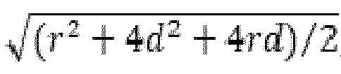

calibration plate 400 and an X-ray source of the X-ray tube. Then, a distance vector T between a pixel point of each concentric circle and the center of the calibration plate can be determined, a component x of the distance vector T on the X axis and a component y of the distance vector T on the Y axis are determined, and thus computation is performed on the basis of a geometric relationship between the concentric circles to determine the 3D coordinates (Δx+x, Δy-y, h) of each pixel point of each concentric circle in the X-ray tube coordinate system. -
FIG. 5 is a structural diagram of an apparatus for calibrating a 3D camera in X-ray imaging according to embodiments of the present disclosure. - As shown in
FIG. 5 , anapparatus 500 for calibrating a 3D camera in X-ray imaging includes: - an acquiring
module 501, configured to acquire a 3D image of a calibration plate captured by a 3D camera, where the calibration plate includes a positioning marker, and the calibration plate has a predetermined distance from an X-ray tube; - a first determining
module 502, configured to determine first 3D coordinates of the positioning marker in a 3D camera coordinate system on the basis of the 3D image; - a second determining
module 503, configured to determine second 3D coordinates of the positioning marker in an X-ray tube coordinate system on the basis of the distance; and - a third determining
module 504, configured to determine, on the basis of the first 3D coordinates and the second 3D coordinates, a transformation matrix adapted to calibrate the 3D camera. - In one embodiment, the center of the calibration plate does not coincide with the radiation field center of the X-ray tube; the calibration plate is disposed in an XY plane including an X axis and a Y axis; and
the acquiring module is further configured to move the calibration plate within the XY plane until the center of the calibration plate coincides with the radiation field center of the X-ray tube. - In one embodiment, the second determining
module 503 is configured to: determine 3D coordinates (0, 0, h) of the center of the calibration plate in the X-ray tube coordinate system, where h represents the distance; determine a distance vector T between the positioning marker and the center of the calibration plate; determine a component x of the distance vector T on the X axis and a component y of the distance vector T on the Y axis; and determine the second 3D coordinates (x, y, h). - In one embodiment, the center of the calibration plate does not coincide with the radiation field center of the X-ray tube; the calibration plate is disposed in an XY plane including an X axis and a Y axis; and the second determining
module 503 is configured to: determine 3D coordinates (Δx, Δy, h) of the center of the calibration plate in the X-ray tube coordinate system, where h represents the distance, Δx represents a component of a distance vector between the radiation field center and the center of the calibration plate on the X axis, and Δy represents a component of the distance vector between the radiation field center and the center of the calibration plate on the Y axis; determine a distance vector T between the positioning marker and the center of the calibration plate; determine a component x of the distance vector T on the X axis and a component y of the distance vector T on the Y axis; and determine the second 3D coordinates (Δx+x, Δy+y, h) of the positioning marker. - In one embodiment, the apparatus further includes: a fourth determining
module 505, configured to determine a set radiation field range and an actual radiation field range on the calibration plate corresponding to the set radiation field range; and determine a radiation field width calibration parameter γw and a radiation field height calibration parameter γh , where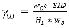

- In one embodiment, the fourth determining
module 505 is configured to: determine the actual radiation field range on the basis of a user input; and make an adjustment to obtain the set radiation field range corresponding to the actual radiation field range; or, determine the set radiation field range on the basis of a user input; and measure the actual radiation field range corresponding to the set radiation field range on the calibration plate. - In one embodiment, the third determining
module 504 is further configured to: adjust the distance m times, and determine the first 3D coordinates and the second 3D coordinates after each distance adjustment, where m is a positive integer greater than or equal to 1; and determine a translation vector T and a rota-tion matrix R, where T -q - Rp and
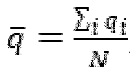

q )(Q -q ) T , qi is the second 3D coordinates determined in an i-th distance adjustment, pi is the first 3D coordinates determined in the i-th distance adjustment, and the value range of i is [0, m]. - Embodiments of the present disclosure further provide an apparatus for calibrating a 3D camera in X-ray imaging having a processor-memory architecture.
FIG. 6 is a structural diagram of an apparatus for calibrating a 3D camera in X-ray imaging having a processor-memory architecture according to embodiments of the present disclosure. - As shown in
FIG. 6 , anapparatus 600 in which an industrial edge application is deployed includes aprocessor 601, amemory 602, and a computer program stored on thememory 602 and capable of running on theprocessor 601, where when executed by theprocessor 601, the computer program implements the method for calibrating a 3D camera in X-ray imaging according to any one of the foregoing embodiments. Thememory 602 may be specifically implemented as various storage media such as an electrically-erasable programmable read-only memory (EEPROM), a flash memory, and a programmable read-only memory (PROM). Theprocessor 601 may be implemented to include one or more central processing units (CPUs) or one or more field-programmable gate arrays, where the field-programmable gate arrays integrate one or more CPU cores. Specifically, the CPU or the CPU core may be implemented as a CPU or an MCU or a DSP or the like. - Not all steps in the foregoing flowchart and not all modules in the foregoing structural diagrams are necessary, and some steps or modules can be omitted according to actual requirements. An execution order of the steps is not fixed and may be adjusted according to requirements. Division of modules is only for the convenience of describing division of functions used. In practical implementation, one module can be implemented by a plurality of modules, and functions of a plurality of modules can also be implemented by a same module. The modules can be located in a same device, and can also be located in different devices.
- Hardware modules in the embodiments can be implemented mechanically or electronically. For example, a hardware module may include a dedicated permanent circuit or logic device (e.g., a dedicated processor, an FPGA or an ASIC) to complete a corresponding operation. A hardware module may also include a programmable logic device or circuit temporarily configured by software (e.g., including a general-purpose processor or other programmable processors) to execute a corresponding operation. For the specific mechanical form, a dedicated permanent circuit or a temporarily configured circuit (configured by software) may be used to implement a hardware module, which can be determined based on costs and time considerations.
- The foregoing descriptions are merely exemplary embodiments of the present disclosure and are not intended to limit the scope of protection of the present disclosure.
Claims (15)
- A method (100) for calibrating a three-dimensional camera in X-ray imaging, the method comprising:acquiring a three-dimensional image of a calibration plate captured by a three-dimensional camera, wherein the calibration plate comprises a positioning marker, and the calibration plate has a predetermined distance from an X-ray tube (101);determining first three-dimensional coordinates of the positioning marker in a three-dimensional camera coordinate system on the basis of the three-dimensional image (102);determining second three-dimensional coordinates of the positioning marker in an X-ray tube coordinate system on the basis of the distance (103); anddetermining, on the basis of the first three-dimensional coordinates and the second three-dimensional coordinates, a transformation matrix adapted to calibrate the three-dimensional camera (104).
- The method (100) according to claim 1, wherein the center of the calibration plate does not coincide with the radiation field center of the X-ray tube; the calibration plate is disposed in an XY plane comprising an X axis and a Y axis; and
the method (100) further comprises:
moving the calibration plate within the XY plane until the center of the calibration plate coincides with the radiation field center of the X-ray tube. - The method (100) according to claim 2, wherein the determining second three-dimensional coordinates of the positioning marker in an X-ray tube coordinate system on the basis of the distance (103) comprises:determining three-dimensional coordinates (0, 0, h) of the center of the calibration plate in the X-ray tube coordinate system, wherein h represents the distance;determining a distance vector T between the positioning marker and the center of the calibration plate;determining a component x of the distance vector T on the X axis and a component y of the distance vector T on the Y axis; anddetermining the second three-dimensional coordinates (x, y, h).
- The method (100) according to claim 1, wherein the center of the calibration plate does not coincide with the radiation field center of the X-ray tube; the calibration plate is disposed in an XY plane comprising an X axis and a Y axis; and
the determining second three-dimensional coordinates of the positioning marker in an X-ray tube coordinate system on the basis of the distance (103) comprises:determining three-dimensional coordinates (Δx, Δy, h) of the center of the calibration plate in the X-ray tube coordinate system, wherein h represents the distance, Δx represents a component of a distance vector between the radiation field center and the center of the calibration plate on the X axis, and Δy represents a component of the distance vector between the radiation field center and the center of the calibration plate on the Y axis;determining a distance vector T between the positioning marker and the center of the calibration plate;determining a component x of the distance vector T on the X axis and a component y of the distance vector T on the Y axis; anddetermining the second three-dimensional coordinates (Δx +x, Δy+y, h) of the positioning marker. - The method (100) according to claim 1, wherein the method further comprises:determining a set radiation field range and an actual radiation field range on the calibration plate corresponding to the set radiation field range; anddetermining a radiation field width calibration parameter γw and a radiation field height calibration parameter γh, wherein


- The method (100) according to claim 5, wherein
the determining a set radiation field range and an actual radiation field range on the calibration plate corresponding to the set radiation field range comprises:determining the actual radiation field range on the basis of a user input; and making an adjustment to obtain the set radiation field range corresponding to the actual radiation field range; ordetermining the set radiation field range on the basis of a user input; and measuring the actual radiation field range corresponding to the set radiation field range. - The method (100) according to claim 1, wherein the method further comprises:adjusting the distance m times, and determining the first three-dimensional coordinates and the second three-dimensional coordinates after each distance adjustment, wherein m is a positive integer greater than or equal to 1; andthe determining, on the basis of the first three-dimensional coordinates and the second three-dimensional coordinates, a transformation matrix adapted to calibrate the three-dimensional camera (104) comprises:determining a translation vector T and a rotation matrix R, wherein

 wherein
q )(Q -q ) T , qi is the second three-dimensional coordinates determined in an i-th distance adjustment, pi is the first three-dimensional coordinates determined in the i-th distance adjustment, and the value range of i is [0, m]; anddetermining the transformation matrix on the basis of the translation vector T and the rotation matrix R. - An apparatus (500) for calibrating a three-dimensional camera in X-ray imaging, the apparatus comprising:an acquiring module (501), configured to acquire a three-dimensional image of a calibration plate captured by a three-dimensional camera, wherein the calibration plate comprises a positioning marker, and the calibration plate has a predetermined distance from an X-ray tube;a first determining module (502), configured to determine first three-dimensional coordinates of the positioning marker in a three-dimensional camera coordinate system on the basis of the three-dimensional image;a second determining module (503), configured to determine second three-dimensional coordinates of the positioning marker in an X-ray tube coordinate system on the basis of the distance; anda third determining module (504), configured to determine, on the basis of the first three-dimensional coordinates and the second three-dimensional coordinates, a transformation matrix adapted to calibrate the three-dimensional camera.
- The apparatus (500) according to claim 8, wherein the center of the calibration plate does not coincide with the radiation field center of the X-ray tube; the calibration plate is disposed in an XY plane comprising an X axis and a Y axis; and
the acquiring module (501) is further configured to move the calibration plate within the XY plane until the center of the calibration plate coincides with the radiation field center of the X-ray tube. - The apparatus (500) according to claim 9, wherein
the second determining module (503) is configured to: determine three-dimensional coordinates (0, 0, h) of the center of the calibration plate in the X-ray tube coordinate system, wherein h represents the distance; determine a distance vector T between the positioning marker and the center of the calibration plate; determine a component x of the distance vector T on the X axis and a component y of the distance vector T on the Y axis; and determine the second three-dimensional coordinates (x, y, h). - The apparatus (500) according to claim 8, wherein the center of the calibration plate does not coincide with the radiation field center of the X-ray tube; the calibration plate is disposed in an XY plane comprising an X axis and a Y axis; and
the second determining module (503) is configured to: determine three-dimensional coordinates (Δx, Δy, h) of the center of the calibration plate in the X-ray tube coordinate system, wherein h represents the distance,Ax represents a component of a distance vector between the radiation field center and the center of the calibration plate on the X axis, and Δy represents a component of the distance vector between the radiation field center and the center of the calibration plate on the Y axis; determine a distance vector T between the positioning marker and the center of the calibration plate; determine a component x of the distance vector T on the X axis and a component y of the distance vector T on the Y axis; and determine the second three-dimensional coordinates (Δx+x, Δy+y, h) of the positioning marker. - The apparatus (500) according to claim 8, wherein the apparatus further comprises:a fourth determining module (505), configured to determine a set radiation field range and an actual radiation field range on the calibration plate corresponding to the set radiation field range; and determine a radiation field width calibration parameter γw and a radiation field height calibration parameter γh , wherein

 wherein the fourth determining module (505) is preferably configured to: determine the actual radiation field range on the basis of a user input; and make an adjustment to obtain the set radiation field range corresponding to the actual radiation field range; or, determine the set radiation field range on the basis of a user input; and measure the actual radiation field range corresponding to the set radiation field range on the calibration plate.
 - The apparatus (500) according to claim 8, wherein
the third determining module (504) is further configured to: adjust the distance m times, and determine the first three-dimensional coordinates and the second three-dimensional coordinates after each distance adjustment, wherein m is a positive integer greater than or equal to 1; and determine a translation vec-tor T and a rotation matrix R, wherein T =q - Rp and
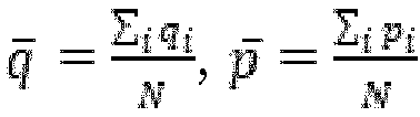
q )(Q -q ) T, qi is the second three-dimensional coordinates determined in an i-th distance adjustment, pi is the first three-dimensional coordinates determined in the i-th distance adjustment, and the value range of i is [0, m]. - An apparatus (600) for calibrating a three-dimensional camera in X-ray imaging, comprising a processor (601) and a memory (602), wherein
the memory (602) stores an application executable by the processor (601) and configured to enable the processor (601) to execute the method (100) for calibrating a three-dimensional camera in X-ray imaging according to any one of claims 1 to 7. - A computer-readable storage medium, having computer-readable instructions stored thereon, wherein the computer-readable instructions are used for implementing the method (100) for calibrating a three-dimensional camera in X-ray imaging according to any one of claims 1 to 7.
Applications Claiming Priority (2)
| Application Number | Priority Date | Filing Date | Title |
|---|---|---|---|
| CN202111413897.7A CN116158771B (en) | 2021-11-25 | 2021-11-25 | Three-dimensional camera calibration method, device and storage medium in X-ray imaging |
| PCT/CN2022/125176 WO2023093347A1 (en) | 2021-11-25 | 2022-10-13 | Method and apparatus for calibrating three-dimensional camera in x-ray imaging, and storage medium |
Publications (4)
| Publication Number | Publication Date |
|---|---|
| EP4419008A1 EP4419008A1 (en) | 2024-08-28 |
| EP4419008C0 EP4419008C0 (en) | 2024-12-25 |
| EP4419008B1 true EP4419008B1 (en) | 2024-12-25 |
| EP4419008B8 EP4419008B8 (en) | 2025-02-19 |
Family
ID=84043790
Family Applications (1)
| Application Number | Title | Priority Date | Filing Date |
|---|---|---|---|
| EP22797261.9A Active EP4419008B8 (en) | 2021-11-25 | 2022-10-13 | Method and apparatus for calibrating three-dimensional camera in x-ray imaging, and storage medium |
Country Status (4)
| Country | Link |
|---|---|
| US (1) | US20240427037A1 (en) |
| EP (1) | EP4419008B8 (en) |
| CN (1) | CN116158771B (en) |
| WO (1) | WO2023093347A1 (en) |
Families Citing this family (1)
| Publication number | Priority date | Publication date | Assignee | Title |
|---|---|---|---|---|
| CN121953885B (en) * | 2026-04-01 | 2026-06-16 | 上海飞机制造有限公司 | A perforated plate calibrator, a data measurement method, and a computed tomography (CT) scanner calibration method. |
Family Cites Families (15)
| Publication number | Priority date | Publication date | Assignee | Title |
|---|---|---|---|---|
| US6533455B2 (en) * | 2000-08-31 | 2003-03-18 | Siemens Aktiengesellschaft | Method for determining a coordinate transformation for use in navigating an object |
| GB2465298B (en) * | 2004-09-24 | 2010-06-30 | Vision Rt Ltd | Image processing system for use with a patient positioning device |
| DE102005033187A1 (en) * | 2005-07-13 | 2007-01-25 | Carl Zeiss Industrielle Messtechnik Gmbh | Measuring arrangement e.g. computed tomography measuring arrangement, calibrating method, involves determining geometry parameter of geometrical model, which describes geometry of arrangement, by evaluation of radiographic image |
| US9554868B2 (en) * | 2009-08-07 | 2017-01-31 | DePuy Synthes Products, Inc. | Method and apparatus for reducing malalignment of fractured bone fragments |
| CN102144927B (en) * | 2010-02-10 | 2012-12-12 | 清华大学 | Motion-compensation-based computed tomography (CT) equipment and method |
| DE102011075527A1 (en) * | 2011-05-09 | 2012-11-15 | Fraunhofer-Gesellschaft zur Förderung der angewandten Forschung e.V. | Radiation system and calibration of the same |
| WO2013016286A2 (en) * | 2011-07-23 | 2013-01-31 | Broncus Medical Inc. | System and method for automatically determining calibration parameters of a fluoroscope |
| ES2588257B1 (en) * | 2015-03-31 | 2017-08-04 | Consejo Superior De Investigaciones Científicas (Csic) | DEVICE FOR REMOVING THREE-DIMENSIONAL INFORMATION FROM RADIOGRAPHIC IMAGES OF AN OBJECT; CALIBRATION PROCEDURE OF SUCH DEVICE; AND PROCEDURE FOR GENERATING SUCH RADIOGRAPHIC IMAGES |
| US9895131B2 (en) * | 2015-10-13 | 2018-02-20 | Siemens Healthcare Gmbh | Method and system of scanner automation for X-ray tube with 3D camera |
| US10478149B2 (en) * | 2017-02-21 | 2019-11-19 | Siemens Healthcare Gmbh | Method of automatically positioning an X-ray source of an X-ray system and an X-ray system |
| US10507002B2 (en) * | 2017-05-23 | 2019-12-17 | Siemens Healthcare Gmbh | X-ray system and method for standing subject |
| CN110559077B (en) * | 2018-06-05 | 2021-08-17 | 武汉联影智融医疗科技有限公司 | Coordinate system registration method, robot control method, device, equipment and medium |
| EP3671111A1 (en) * | 2018-12-18 | 2020-06-24 | Agfa Nv | Method for calibrating a 3d camera for patient thickness measurements |
| CN118762087A (en) * | 2019-06-12 | 2024-10-11 | 通用电气精准医疗有限责任公司 | 3D camera-medical imaging equipment coordinate system calibration system and method and its application |
| EP4221581A4 (en) * | 2020-10-01 | 2024-10-30 | True Digital Surgery | AUTO-NAVIGATING DIGITAL SURGICAL MICROSCOPE |
-
2021
- 2021-11-25 CN CN202111413897.7A patent/CN116158771B/en active Active
-
2022
- 2022-10-13 US US18/694,011 patent/US20240427037A1/en active Pending
- 2022-10-13 WO PCT/CN2022/125176 patent/WO2023093347A1/en not_active Ceased
- 2022-10-13 EP EP22797261.9A patent/EP4419008B8/en active Active
Also Published As
| Publication number | Publication date |
|---|---|
| US20240427037A1 (en) | 2024-12-26 |
| EP4419008A1 (en) | 2024-08-28 |
| CN116158771B (en) | 2026-05-22 |
| EP4419008C0 (en) | 2024-12-25 |
| EP4419008B8 (en) | 2025-02-19 |
| CN116158771A (en) | 2023-05-26 |
| WO2023093347A1 (en) | 2023-06-01 |
Similar Documents
| Publication | Publication Date | Title |
|---|---|---|
| US12194634B2 (en) | Error detection method and robot system based on a plurality of pose identifications | |
| CN102961154B (en) | Regulate the method for exposure field of x-ray system and device and x-ray system | |
| US11270465B2 (en) | Multiple camera calibration | |
| CN105828722B (en) | Ultrasonic probe calibration based on electromagnetic tracker | |
| CN111132730B (en) | Calibration method for a patient monitoring system for use with a radiation therapy device | |
| EP3254621A1 (en) | 3d image special calibrator, surgical localizing system and method | |
| US20230397957A1 (en) | Surgical navigation system with flat panel registration fixture | |
| US11051783B2 (en) | X-ray radiography apparatus | |
| US20080043237A1 (en) | Automatic laser alignment system | |
| US20240338816A1 (en) | Method for Recognizing Posture of Human Body Parts To Be Detected Based on Photogrammetry | |
| EP4209312A1 (en) | Error detection method and robot system based on association identification | |
| EP3878510B1 (en) | Process and apparatus to determine linac isocenter | |
| CN115511961A (en) | Three-dimensional space positioning method, system and storage medium | |
| EP3295887A1 (en) | Robotic fluoroscopic navigation | |
| WO2023093347A1 (en) | Method and apparatus for calibrating three-dimensional camera in x-ray imaging, and storage medium | |
| US20230248467A1 (en) | Method of medical navigation | |
| US11213263B2 (en) | System and method for positioning a mobile medical imaging system | |
| CN113963057A (en) | Imaging geometric relation calibration method and device, electronic equipment and storage medium | |
| EP4505944B1 (en) | Method and device for determining target detection region of ionization chamber, and storage medium | |
| CN116919592A (en) | Navigation method and system based on C-arm machine image | |
| KR20190060506A (en) | Method for Arranging Long Distance Stereo Camera Using Lasor System | |
| EP4702930A1 (en) | Method and apparatus for alignment of tube and detector plate in x-ray imaging system, and system | |
| CN115120256B (en) | Automatic X-ray equipment and shooting method thereof | |
| US20250124589A1 (en) | Radiation irradiation apparatus, operation method of radiation irradiation apparatus, and operation program | |
| CN117462267A (en) | A method for aiming robot end effectors under perspective guidance |
Legal Events
| Date | Code | Title | Description |
|---|---|---|---|
| STAA | Information on the status of an ep patent application or granted ep patent |
Free format text: STATUS: UNKNOWN |
|
| STAA | Information on the status of an ep patent application or granted ep patent |
Free format text: STATUS: THE INTERNATIONAL PUBLICATION HAS BEEN MADE |
|
| PUAI | Public reference made under article 153(3) epc to a published international application that has entered the european phase |
Free format text: ORIGINAL CODE: 0009012 |
|
| STAA | Information on the status of an ep patent application or granted ep patent |
Free format text: STATUS: REQUEST FOR EXAMINATION WAS MADE |
|
| 17P | Request for examination filed |
Effective date: 20240522 |
|
| AK | Designated contracting states |
Kind code of ref document: A1 Designated state(s): AL AT BE BG CH CY CZ DE DK EE ES FI FR GB GR HR HU IE IS IT LI LT LU LV MC ME MK MT NL NO PL PT RO RS SE SI SK SM TR |
|
| GRAP | Despatch of communication of intention to grant a patent |
Free format text: ORIGINAL CODE: EPIDOSNIGR1 |
|
| STAA | Information on the status of an ep patent application or granted ep patent |
Free format text: STATUS: GRANT OF PATENT IS INTENDED |
|
| RIC1 | Information provided on ipc code assigned before grant |
Ipc: H04N 17/00 20060101ALI20240912BHEP Ipc: H04N 23/30 20230101ALI20240912BHEP Ipc: G06T 7/80 20170101ALI20240912BHEP Ipc: G01S 17/894 20200101ALI20240912BHEP Ipc: G01B 21/04 20060101ALI20240912BHEP Ipc: G01B 15/00 20060101ALI20240912BHEP Ipc: G01B 11/245 20060101ALI20240912BHEP Ipc: A61B 6/58 20240101ALI20240912BHEP Ipc: A61B 5/00 20060101ALI20240912BHEP Ipc: A61B 5/107 20060101ALI20240912BHEP Ipc: G01B 11/00 20060101ALI20240912BHEP Ipc: G01B 11/24 20060101ALI20240912BHEP Ipc: G01S 17/06 20060101ALI20240912BHEP Ipc: G01S 17/89 20200101ALI20240912BHEP Ipc: G06T 7/70 20170101ALI20240912BHEP Ipc: A61B 6/00 20240101AFI20240912BHEP |
|
| DAV | Request for validation of the european patent (deleted) | ||
| DAX | Request for extension of the european patent (deleted) | ||
| INTG | Intention to grant announced |
Effective date: 20240927 |
|
| GRAS | Grant fee paid |
Free format text: ORIGINAL CODE: EPIDOSNIGR3 |
|
| GRAA | (expected) grant |
Free format text: ORIGINAL CODE: 0009210 |
|
| STAA | Information on the status of an ep patent application or granted ep patent |
Free format text: STATUS: THE PATENT HAS BEEN GRANTED |
|
| AK | Designated contracting states |
Kind code of ref document: B1 Designated state(s): AL AT BE BG CH CY CZ DE DK EE ES FI FR GB GR HR HU IE IS IT LI LT LU LV MC ME MK MT NL NO PL PT RO RS SE SI SK SM TR |
|
| REG | Reference to a national code |
Ref country code: GB Ref legal event code: FG4D |
|
| REG | Reference to a national code |
Ref country code: CH Ref legal event code: EP |
|
| REG | Reference to a national code |
Ref country code: DE Ref legal event code: R096 Ref document number: 602022009175 Country of ref document: DE |
|
| RAP4 | Party data changed (patent owner data changed or rights of a patent transferred) |
Owner name: SIEMENS SHANGHAI MEDICAL EQUIPMENT LTD. |
|
| REG | Reference to a national code |
Ref country code: IE Ref legal event code: FG4D |
|
| REG | Reference to a national code |
Ref country code: CH Ref legal event code: PK Free format text: BERICHTIGUNG B8 |
|
| U01 | Request for unitary effect filed |
Effective date: 20250102 |
|
| U07 | Unitary effect registered |
Designated state(s): AT BE BG DE DK EE FI FR IT LT LU LV MT NL PT RO SE SI Effective date: 20250114 |
|
| PG25 | Lapsed in a contracting state [announced via postgrant information from national office to epo] |
Ref country code: HR Free format text: LAPSE BECAUSE OF FAILURE TO SUBMIT A TRANSLATION OF THE DESCRIPTION OR TO PAY THE FEE WITHIN THE PRESCRIBED TIME-LIMIT Effective date: 20241225 |
|
| PG25 | Lapsed in a contracting state [announced via postgrant information from national office to epo] |
Ref country code: NO Free format text: LAPSE BECAUSE OF FAILURE TO SUBMIT A TRANSLATION OF THE DESCRIPTION OR TO PAY THE FEE WITHIN THE PRESCRIBED TIME-LIMIT Effective date: 20250325 |
|
| PG25 | Lapsed in a contracting state [announced via postgrant information from national office to epo] |
Ref country code: GR Free format text: LAPSE BECAUSE OF FAILURE TO SUBMIT A TRANSLATION OF THE DESCRIPTION OR TO PAY THE FEE WITHIN THE PRESCRIBED TIME-LIMIT Effective date: 20250326 |
|
| PG25 | Lapsed in a contracting state [announced via postgrant information from national office to epo] |
Ref country code: RS Free format text: LAPSE BECAUSE OF FAILURE TO SUBMIT A TRANSLATION OF THE DESCRIPTION OR TO PAY THE FEE WITHIN THE PRESCRIBED TIME-LIMIT Effective date: 20250325 |
|
| PG25 | Lapsed in a contracting state [announced via postgrant information from national office to epo] |
Ref country code: SM Free format text: LAPSE BECAUSE OF FAILURE TO SUBMIT A TRANSLATION OF THE DESCRIPTION OR TO PAY THE FEE WITHIN THE PRESCRIBED TIME-LIMIT Effective date: 20241225 |
|
| PG25 | Lapsed in a contracting state [announced via postgrant information from national office to epo] |
Ref country code: PL Free format text: LAPSE BECAUSE OF FAILURE TO SUBMIT A TRANSLATION OF THE DESCRIPTION OR TO PAY THE FEE WITHIN THE PRESCRIBED TIME-LIMIT Effective date: 20241225 |
|
| PG25 | Lapsed in a contracting state [announced via postgrant information from national office to epo] |
Ref country code: ES Free format text: LAPSE BECAUSE OF FAILURE TO SUBMIT A TRANSLATION OF THE DESCRIPTION OR TO PAY THE FEE WITHIN THE PRESCRIBED TIME-LIMIT Effective date: 20241225 |
|
| PG25 | Lapsed in a contracting state [announced via postgrant information from national office to epo] |
Ref country code: IS Free format text: LAPSE BECAUSE OF FAILURE TO SUBMIT A TRANSLATION OF THE DESCRIPTION OR TO PAY THE FEE WITHIN THE PRESCRIBED TIME-LIMIT Effective date: 20250425 |
|
| PG25 | Lapsed in a contracting state [announced via postgrant information from national office to epo] |
Ref country code: SK Free format text: LAPSE BECAUSE OF FAILURE TO SUBMIT A TRANSLATION OF THE DESCRIPTION OR TO PAY THE FEE WITHIN THE PRESCRIBED TIME-LIMIT Effective date: 20241225 |
|
| PG25 | Lapsed in a contracting state [announced via postgrant information from national office to epo] |
Ref country code: CZ Free format text: LAPSE BECAUSE OF FAILURE TO SUBMIT A TRANSLATION OF THE DESCRIPTION OR TO PAY THE FEE WITHIN THE PRESCRIBED TIME-LIMIT Effective date: 20241225 |
|
| PLBE | No opposition filed within time limit |
Free format text: ORIGINAL CODE: 0009261 |
|
| STAA | Information on the status of an ep patent application or granted ep patent |
Free format text: STATUS: NO OPPOSITION FILED WITHIN TIME LIMIT |
|
| REG | Reference to a national code |
Ref country code: CH Ref legal event code: L10 Free format text: ST27 STATUS EVENT CODE: U-0-0-L10-L00 (AS PROVIDED BY THE NATIONAL OFFICE) Effective date: 20251105 |
|
| U20 | Renewal fee for the european patent with unitary effect paid |
Year of fee payment: 4 Effective date: 20251020 |
|
| 26N | No opposition filed |
Effective date: 20250926 |
|
| REG | Reference to a national code |
Ref country code: CH Ref legal event code: H13 Free format text: ST27 STATUS EVENT CODE: U-0-0-H10-H13 (AS PROVIDED BY THE NATIONAL OFFICE) Effective date: 20260527 |
|
| PG25 | Lapsed in a contracting state [announced via postgrant information from national office to epo] |
Ref country code: MC Free format text: LAPSE BECAUSE OF FAILURE TO SUBMIT A TRANSLATION OF THE DESCRIPTION OR TO PAY THE FEE WITHIN THE PRESCRIBED TIME-LIMIT Effective date: 20241225 |
|
| PG25 | Lapsed in a contracting state [announced via postgrant information from national office to epo] |
Ref country code: CH Free format text: LAPSE BECAUSE OF NON-PAYMENT OF DUE FEES Effective date: 20251031 |