EP4418637A1 - Housing assembly, control method and system, and electronic device - Google Patents
Housing assembly, control method and system, and electronic device Download PDFInfo
- Publication number
- EP4418637A1 EP4418637A1 EP22880207.0A EP22880207A EP4418637A1 EP 4418637 A1 EP4418637 A1 EP 4418637A1 EP 22880207 A EP22880207 A EP 22880207A EP 4418637 A1 EP4418637 A1 EP 4418637A1
- Authority
- EP
- European Patent Office
- Prior art keywords
- assembly
- locking
- shell
- locking key
- state
- Prior art date
- Legal status (The legal status is an assumption and is not a legal conclusion. Google has not performed a legal analysis and makes no representation as to the accuracy of the status listed.)
- Pending
Links
Images



Classifications
-
- H—ELECTRICITY
- H04—ELECTRIC COMMUNICATION TECHNIQUE
- H04M—TELEPHONIC COMMUNICATION
- H04M1/00—Substation equipment, e.g. for use by subscribers
- H04M1/02—Constructional features of telephone sets
- H04M1/0202—Portable telephone sets, e.g. cordless phones, mobile phones or bar type handsets
- H04M1/0206—Portable telephones comprising a plurality of mechanically joined movable body parts, e.g. hinged housings
- H04M1/0208—Portable telephones comprising a plurality of mechanically joined movable body parts, e.g. hinged housings characterized by the relative motions of the body parts
- H04M1/0214—Foldable telephones, i.e. with body parts pivoting to an open position around an axis parallel to the plane they define in closed position
-
- H—ELECTRICITY
- H04—ELECTRIC COMMUNICATION TECHNIQUE
- H04M—TELEPHONIC COMMUNICATION
- H04M1/00—Substation equipment, e.g. for use by subscribers
- H04M1/02—Constructional features of telephone sets
- H04M1/0202—Portable telephone sets, e.g. cordless phones, mobile phones or bar type handsets
- H04M1/0206—Portable telephones comprising a plurality of mechanically joined movable body parts, e.g. hinged housings
- H04M1/0208—Portable telephones comprising a plurality of mechanically joined movable body parts, e.g. hinged housings characterized by the relative motions of the body parts
- H04M1/0214—Foldable telephones, i.e. with body parts pivoting to an open position around an axis parallel to the plane they define in closed position
- H04M1/0216—Foldable in one direction, i.e. using a one degree of freedom hinge
-
- H—ELECTRICITY
- H04—ELECTRIC COMMUNICATION TECHNIQUE
- H04M—TELEPHONIC COMMUNICATION
- H04M1/00—Substation equipment, e.g. for use by subscribers
- H04M1/02—Constructional features of telephone sets
- H04M1/0202—Portable telephone sets, e.g. cordless phones, mobile phones or bar type handsets
- H04M1/0206—Portable telephones comprising a plurality of mechanically joined movable body parts, e.g. hinged housings
- H04M1/0208—Portable telephones comprising a plurality of mechanically joined movable body parts, e.g. hinged housings characterized by the relative motions of the body parts
- H04M1/0214—Foldable telephones, i.e. with body parts pivoting to an open position around an axis parallel to the plane they define in closed position
- H04M1/0216—Foldable in one direction, i.e. using a one degree of freedom hinge
- H04M1/022—The hinge comprising two parallel pivoting axes
-
- G—PHYSICS
- G06—COMPUTING OR CALCULATING; COUNTING
- G06F—ELECTRIC DIGITAL DATA PROCESSING
- G06F1/00—Details not covered by groups G06F3/00 - G06F13/00 and G06F21/00
- G06F1/16—Constructional details or arrangements
- G06F1/1613—Constructional details or arrangements for portable computers
- G06F1/1633—Constructional details or arrangements of portable computers not specific to the type of enclosures covered by groups G06F1/1615 - G06F1/1626
- G06F1/1675—Miscellaneous details related to the relative movement between the different enclosures or enclosure parts
- G06F1/1679—Miscellaneous details related to the relative movement between the different enclosures or enclosure parts for locking or maintaining the movable parts of the enclosure in a fixed position, e.g. latching mechanism at the edge of the display in a laptop or for the screen protective cover of a PDA
-
- H—ELECTRICITY
- H04—ELECTRIC COMMUNICATION TECHNIQUE
- H04M—TELEPHONIC COMMUNICATION
- H04M1/00—Substation equipment, e.g. for use by subscribers
- H04M1/02—Constructional features of telephone sets
- H04M1/0202—Portable telephone sets, e.g. cordless phones, mobile phones or bar type handsets
- H04M1/0206—Portable telephones comprising a plurality of mechanically joined movable body parts, e.g. hinged housings
- H04M1/0208—Portable telephones comprising a plurality of mechanically joined movable body parts, e.g. hinged housings characterized by the relative motions of the body parts
- H04M1/0235—Slidable or telescopic telephones, i.e. with a relative translation movement of the body parts; Telephones using a combination of translation and other relative motions of the body parts
-
- H—ELECTRICITY
- H04—ELECTRIC COMMUNICATION TECHNIQUE
- H04M—TELEPHONIC COMMUNICATION
- H04M1/00—Substation equipment, e.g. for use by subscribers
- H04M1/02—Constructional features of telephone sets
- H04M1/0202—Portable telephone sets, e.g. cordless phones, mobile phones or bar type handsets
- H04M1/0249—Details of the mechanical connection between the housing parts or relating to the method of assembly
-
- G—PHYSICS
- G06—COMPUTING OR CALCULATING; COUNTING
- G06F—ELECTRIC DIGITAL DATA PROCESSING
- G06F1/00—Details not covered by groups G06F3/00 - G06F13/00 and G06F21/00
- G06F1/16—Constructional details or arrangements
- G06F1/1613—Constructional details or arrangements for portable computers
- G06F1/1615—Constructional details or arrangements for portable computers with several enclosures having relative motions, each enclosure supporting at least one I/O or computing function
- G06F1/1616—Constructional details or arrangements for portable computers with several enclosures having relative motions, each enclosure supporting at least one I/O or computing function with folding flat displays, e.g. laptop computers or notebooks having a clamshell configuration, with body parts pivoting to an open position around an axis parallel to the plane they define in closed position
-
- G—PHYSICS
- G06—COMPUTING OR CALCULATING; COUNTING
- G06F—ELECTRIC DIGITAL DATA PROCESSING
- G06F1/00—Details not covered by groups G06F3/00 - G06F13/00 and G06F21/00
- G06F1/16—Constructional details or arrangements
- G06F1/1613—Constructional details or arrangements for portable computers
- G06F1/1633—Constructional details or arrangements of portable computers not specific to the type of enclosures covered by groups G06F1/1615 - G06F1/1626
- G06F1/1637—Details related to the display arrangement, including those related to the mounting of the display in the housing
- G06F1/1652—Details related to the display arrangement, including those related to the mounting of the display in the housing the display being flexible, e.g. mimicking a sheet of paper, or rollable
-
- H—ELECTRICITY
- H04—ELECTRIC COMMUNICATION TECHNIQUE
- H04M—TELEPHONIC COMMUNICATION
- H04M1/00—Substation equipment, e.g. for use by subscribers
- H04M1/02—Constructional features of telephone sets
- H04M1/0202—Portable telephone sets, e.g. cordless phones, mobile phones or bar type handsets
- H04M1/026—Details of the structure or mounting of specific components
- H04M1/0266—Details of the structure or mounting of specific components for a display module assembly
- H04M1/0268—Details of the structure or mounting of specific components for a display module assembly including a flexible display panel
Definitions
- This application pertains to the field of electronic device technologies, and in particular, to a shell assembly, a shell assembly control method, a shell assembly control system, an electronic device, and a storage medium.
- the screens of electronic devices are made foldable.
- the lack of support for the screen after the screen is opened to a specific angle makes it difficult to keep the screen stable at that specific opening angle.
- This application aims to solve at least one of the technical problems existing in the prior art or related art.
- a first aspect of this application provides a shell assembly.
- a second aspect of this application provides a shell assembly control method.
- a third aspect of this application provides a shell assembly control system.
- a fourth aspect of this application provides an electronic device.
- a fifth aspect of this application provides a storage medium.
- a first aspect of this application provides a shell assembly, including: at least two shells, a hinge, a linkage assembly, a locking assembly, a locking key, and a driving assembly.
- the at least two shells include a first shell.
- the at least two shells are connected through the hinge, and the at least two shells are able to rotate relative to the hinge.
- a first end of the linkage assembly is connected to the hinge, and a second end of the linkage assembly extends into the first shell and is movably connected to the first shell.
- the locking assembly is provided on the first shell and opposite the second end of the linkage assembly, the locking assembly having a first state and a second state.
- the locking assembly In a case that the locking assembly is in the first state, the locking assembly is separated from the second end of the linkage assembly; and in a case that the locking assembly is in the second state, the locking assembly abuts against the second end of the linkage assembly.
- the locking key is provided on the first shell and is in contact with the locking assembly.
- the driving assembly is connected to the locking key to drive, through the locking key, the locking assembly to switch between the first state and the second state.
- the shell assembly includes at least two shells, a hinge, a linkage assembly, a locking assembly, a locking key, and a driving assembly.
- the locking key is provided on the first shell and is in contact with the locking assembly.
- the driving assembly is connected to the locking key, and the driving assembly is able to drive, through the locking key, the locking assembly to switch between the first state and the second state.
- the locking assembly is in the first state, the locking assembly is separated from the second end of the linkage assembly, and the hinge is able to rotate; and in a case that the locking assembly is in the second state, the locking assembly abuts against the second end of the linkage assembly, and the second end of the linkage assembly is stationary relative to the first shell to fix the hinge.
- Locking the linkage assembly stabilizes the opening angle of the first shell and in addition, the hinge can be fixed through the linkage assembly, enabling the first shell to stably maintain a specific opening angle. This ensures that the screen of the electronic device stably remains at an opening angle, enhancing the stability of the shell during electronic device usage and improving the user experience of the electronic device.
- the shell assembly includes at least two shells and a hinge, and the at least two shells are connected through the hinge, such that the at least two shells can rotate relative to each other, and the at least two shells can also rotate relative to the hinge.
- the shell assembly further includes a linkage assembly and a locking assembly. A first end of the linkage assembly is connected to the hinge, and a second end of the linkage assembly extends into the first shell and is movably connected to the first shell.
- the locking assembly is provided on the first shell and can switch between a first state and a second state.
- the locking assembly In a case that the locking assembly is in the first state, the locking assembly is separated from the second end of the linkage assembly, and the hinge rotates, allowing the second end of the linkage assembly to be movably connected to the first shell, enabling the first shell to freely rotate relative to the hinge. In a case that the locking assembly is in the second state, the locking assembly abuts against the second end of the linkage assembly and the second end of the linkage assembly remains stationary relative to the first shell to fix the hinge and maintain a specific angle between the first shell and the hinge.
- the shell assembly further includes a driving assembly and the driving assembly is securely connected to the locking key. With an electric field applied to two ends of the driving assembly, the driving assembly can undergo expansion or contraction deformation. This deformation drives the locking key to move, which in turn drives the locking assembly to switch between the first state and the second state.
- the opening angle of the first shell can be limited through the linkage assembly, and the hinge can be fixed through the linkage assembly, such that the first shell can be more stably maintained at that opening angle, and consequently the screen of the electronic device can be more stably maintained at that opening angle.
- the state of the locking assembly can be manually controlled using the locking key; or the driving assembly can be used to drive the locking key, which in turn drives the locking assembly to electrically switch between states. This enhances flexibility in usage and improves the user experience.
- a second aspect of this application provides a shell assembly control method, including: controlling, based on operation information of a locking key, a driving assembly to drive a locking assembly to switch to a first state; controlling at least two shells to move to a position corresponding to the operation information; and controlling the driving assembly to drive the locking assembly to switch to a second state.
- the shell assembly is provided with a driving assembly, and the driving assembly is connected to the locking key.
- the driving assembly can be controlled, based on the operation information of the locking key, to drive the locking key, which in turn drives the locking assembly to switch between the first state and the second state, realizing electrical control of the state of the locking assembly.
- the state of the locking assembly can be manually controlled using the locking key; or the driving assembly can be used to drive the locking key, which in turn drives the locking assembly to switch between states. This enhances flexibility in usage and improves the user experience on the electronic device.
- the locking assembly is provided on a shell and can switch between a first state and a second state.
- the shell can freely rotate relative to the hinge.
- the shell assembly further includes a locking key, and the locking key is provided on the shell and in contact with the locking assembly.
- the locking key is configured to control the movement of the locking assembly, implementing control over the state of the locking assembly.
- the locking assembly In a case that the locking assembly is in the second state, the locking assembly abuts against the second end of the linkage assembly and the second end of the linkage assembly remains stationary relative to the first shell to fix the hinge and maintain a specific angle between the first shell and the hinge.
- a third aspect of this application provides a shell assembly control system, including a first switching unit, a control unit, and a second switching unit.
- the control system is configured to: control, based on operation information of a locking key, a driving assembly to drive a locking assembly to switch to a first state; control at least two shells to move to a position corresponding to the operation information; and control the driving assembly to drive the locking assembly to switch to a second state.
- the shell assembly control system includes a first switching unit, a control unit, and a second switching unit.
- the shell assembly is provided with a driving assembly, and the driving assembly is connected to the locking key.
- the driving assembly can be controlled, based on the operation information of the locking key, to drive the locking key, which in turn drives the locking assembly to switch between the first state and the second state, realizing electrical control of the state of the locking assembly.
- the state of the locking assembly can be manually controlled using the locking key; or the driving assembly can be used to drive the locking key, which in turn drives the locking assembly to switch between states. This enhances flexibility in usage and improves the user experience on the electronic device.
- the locking assembly is provided on a shell and can switch between a first state and a second state.
- the shell can freely rotate relative to the hinge.
- the shell assembly further includes a locking key, and the locking key is provided on the shell and in contact with the locking assembly.
- the locking key is configured to control the movement of the locking assembly, implementing control over the state of the locking assembly.
- the locking assembly In a case that the locking assembly is in the second state, the locking assembly abuts against the second end of the linkage assembly and the second end of the linkage assembly remains stationary relative to the first shell to fix the hinge and maintain a specific angle between the first shell and the hinge.
- a fourth aspect of this application provides an electronic device, including a shell assembly according to any one of the foregoing technical solutions; or including a memory and a processor, where the memory is configured to store executable instructions, and the processor is configured to execute stored instructions to implement the steps of the shell assembly control method according to any one of the foregoing technical solutions.
- the electronic device provided in this application has all the beneficial effects of the shell assembly according to any one of the foregoing technical solutions as it includes the shell assembly. Details are not described herein again.
- the electronic device includes a memory and a processor, where the processor is capable of executing the instructions stored in the memory to implement the steps of the shell assembly control method according to any one of the foregoing technical solutions, and therefore has all the beneficial effects of the shell assembly control method. Details are not described herein again.
- a fifth aspect of the application further provides an electronic device, configured to perform the steps of the shell assembly control method according to the second aspect.
- a sixth aspect of this application provides a storage medium, where a computer program is stored and when the computer program is executed by a processor, the steps of the shell assembly control method according to any one of the foregoing technical solutions are implemented.
- the storage medium provided in this application is stored with a computer program and when the computer program is executed by a processor, the steps of the shell assembly control method according to any one of the foregoing technical solutions are implemented. Therefore, the storage medium has all the beneficial effects of the shell assembly control method. Details are not described herein again.
- a seventh aspect of this application provides a computer program product, where the computer program is able to be executed by a processor to implement the steps of the shell assembly control method according to the second aspect.
- An eighth aspect of this application provides a chip, where the chip includes a processor and a communication interface.
- the communication interface is coupled to the processor, and the processor is configured to run a program or instructions to implement the shell assembly control method according to the second aspect.
- FIG. 1 to FIG. 8 The corresponding relationship between reference signs and part names in FIG. 1 to FIG. 8 is as follows: 100. shell, 110. key cover, 200. hinge, 210. hinge body, 220. first connecting shaft, 230. first connecting portion, 240. second connecting shaft, 250. second connecting portion, 260. first gear, 270. second gear, 280. third gear, 300. linkage assembly, 310. first connecting rod, 320. second connecting rod, 330. pin, 400. locking assembly, 410. bracket, 412. Bracke body, 414. first sliding groove, 416. second sliding groove, 418. guiding hole, 419. fixing post, 420. slider, 422. slider body, 424. first guiding surface, 430. elastic member, 440. ball, 500. third sliding groove, 600.
- locking key 610. locking key body, 620. toggle portion, 630. second guiding surface, 710 driving assembly, 720. piezoelectric component, 730. first electrode, 740. second electrode, 750. power storage component, 760. clamping component, 770. clamping groove, 780. mounting groove, 800. main board, 810. fingerprint circuit board, 820. fingerprint module, 830. piezoelectric circuit board, 840. driving motor, 850. double-sided adhesive tape, 860. fingerprint protection cover, 870. fingerprint sensor, 880. fingerprint key, 910. fingerprint circuit pad, and 920. fingerprint circuit board connector.
- the following describes a shell assembly, a shell assembly control method, a shell assembly control system, an electronic device, and a storage medium according to some embodiments of this application with reference to FIGs. 1 to 8 .
- This embodiment provides a shell assembly, as shown in FIGs. 1 to 8 , including: at least two shells 100, a hinge 200, a linkage assembly 300, a locking assembly 400, a locking key 600, and a driving assembly 710.
- the at least two shells 100 include a first shell.
- the at least two shells 100 are connected through the hinge 200, and the at least two shells 100 are able to rotate relative to the hinge 200.
- a first end of the linkage assembly 300 is connected to the hinge 200, and a second end of the linkage assembly 300 extends into the first shell and is movably connected to the first shell.
- the locking assembly 400 is provided on the first shell and opposite the second end of the linkage assembly 300, the locking assembly 400 having a first state and a second state.
- the locking assembly 400 In a case that the locking assembly 400 is in the first state, the locking assembly 400 is separated from the second end of the linkage assembly 300; and in a case that the locking assembly 400 is in the second state, the locking assembly 400 abuts against the second end of the linkage assembly 300.
- the locking key 600 is provided on the first shell and is in contact with the locking assembly 400.
- the driving assembly 710 is connected to the locking key 600 to drive, through the locking key 600, the locking assembly 400 to switch between the first state and the second state.
- the shell assembly includes at least two shells 100, a hinge 200, a linkage assembly 300, a locking assembly 400, a locking key 600, and a driving assembly 710.
- the locking key 600 is provided on the first shell and is in contact with the locking assembly 400.
- the driving assembly 710 is connected to the locking key 600 such that the driving assembly 710 can drive the locking key 600, which in turn drives the locking assembly 400 to switch between the first state and the second state.
- the locking assembly 400 is separated from the second end of the linkage assembly 300, and the hinge 200 is able to rotate; and in a case that the locking assembly 400 is in the second state, the locking assembly 400 abuts against the second end of the linkage assembly 300.
- the second end of the linkage assembly 300 is stationary relative to the first shell to fix the hinge 200.
- the purpose of locking and releasing the linkage assembly 300 is achieved.
- Locking the linkage assembly 300 stabilizes the opening angle of the first shell and in addition, the hinge 200 can be fixed through the linkage assembly 300, enabling the first shell to stably maintain a specific opening angle. This ensures that the screen of the electronic device stably remains at an opening angle, enhancing the stability of the shell 100 during electronic device usage and improving the user experience of the electronic device.
- the shell assembly includes at least two shells 100 and a hinge 200, and the at least two shells 100 are connected through the hinge 200, thereby making the at least two shells 100 rotatable relative to each other, and the at least two shells 100 are also rotatable relative to the hinge 200.
- the shell assembly further includes a linkage assembly 300 and a locking assembly 400.
- a first end of the linkage assembly 300 is connected to the hinge 200, and a second end of the linkage assembly 300 extends into the first shell and is movably connected to the first shell.
- the locking assembly 400 is provided on the first shell and can switch between a first state and a second state.
- the locking assembly 400 In a case that the locking assembly 400 is in the first state, the locking assembly 400 is separated from the second end of the linkage assembly 300, and the hinge 200 rotates, allowing the second end of the linkage assembly 300 to be movably connected to the first shell, enabling the first shell to freely rotate relative to the hinge 200. In a case that the locking assembly 400 is in the second state, the locking assembly 400 abuts against the second end of the linkage assembly 300 and the second end of the linkage assembly 300 remains stationary relative to the first shell to fix the hinge 200 and maintain a specific angle between the first shell and the hinge 200.
- the shell assembly further includes a driving assembly 710, where the driving assembly 710 is installed in the sliding groove on the inner surface of the key cover 110 and is snap fitted at the corresponding position of the shell 100.
- the driving assembly 710 is securely connected to the locking key 600. Through the application of an electric field to both ends of the driving assembly 710, the driving assembly 710 undergoes expansion or contraction deformation. This deformation drives the movement of the locking key 600, which in turn drives the locking assembly 400 to switch between the first state and the second state.
- the opening angle of the first shell can be limited through the linkage assembly 300.
- the first shell can be more stably maintained at that opening angle through the fixing of the hinge 200 by the linkage assembly 300. This ensures that the screen of the electronic device to be more stably maintained at that opening angle, enhancing the overall stability of the electronic device and improving the user experience of the electronic device.
- the state of the locking assembly 400 can be manually controlled using the locking key 600; or the driving assembly 710 can be used to drive the locking key 600, which in turn drives the locking assembly 400 to electrically switch between states. This enhances flexibility in usage and improves the user experience.
- This embodiment provides a shell assembly.
- this embodiment further includes the following technical features.
- the driving assembly 710 includes: a piezoelectric component 720, a first electrode 730, a second electrode 740, and a power storage component 750.
- a first end of the piezoelectric component 720 is connected to the locking key 600.
- the first electrode 730 is provided between the first end of the piezoelectric component 720 and the locking key 600.
- the second electrode 740 is provided at a second end of the piezoelectric component 720.
- Two poles of the power storage component 750 are respectively connected to the first electrode 730 and the second electrode 740.
- the driving assembly 710 includes a piezoelectric component 720, a first electrode 730, and a second electrode 740.
- the first end of the piezoelectric component 720 is connected to the locking key 600.
- the first electrode 730 is provided between the first end of the piezoelectric component 720 and the locking key 600.
- the second electrode 740 is provided at the second end of the piezoelectric component 720.
- the driving assembly 710 further includes a power storage component 750.
- the power storage component 750 is adhered to the bracket 410 through a double-sided adhesive tape 850 and two poles of the power storage component 750 are respectively connected to the first electrode 730 and the second electrode 740.
- An electric field is applied to the first electrode 730 and the second electrode 740 through the power storage component 750, such that the electric field is applied to two ends of the piezoelectric component 720, causing the piezoelectric component 720 to mechanically deform under the action of the inverse piezoelectric effect, driving the locking key 600 to move to a designated position, and consequently driving the locking assembly 400 to move, thereby implementing the locking/unlocking function.
- the piezoelectric component 720 can obtain stable driving power, thereby improving the operational stability and reliability of the piezoelectric component 720.
- a positive or negative voltage is applied to two ends of the piezoelectric component 720 by utilizing the inverse piezoelectric effect of the piezoelectric component 720, such that the piezoelectric component 720 is extended or compressed by a corresponding displacement amount, driving the locking key 600 to move to a designated position.
- the locking assembly 400 is driven to move, implementing the locking/unlocking function.
- the inverse piezoelectric effect refers to the phenomenon that when an electric field is applied in the polarization direction of dielectrics, these dielectrics will generate mechanical deformation or mechanical stress in a certain direction, and when the applied electric field is removed, this deformation or stress will also disappear.
- an electric field can be applied to the piezoelectric component 720 to make the piezoelectric component 720 to generate a mechanical deformation, thereby generating a force to drive the locking key 600 to move and achieving the effect of driving the locking assembly 400 to move.
- the locking/unlocking action of the locking assembly 400 can be implemented by manually manipulating the locking key 600 to drive the locking assembly 400 to move.
- the piezoelectric effect of the piezoelectric component 720 can be used to charge the power storage component 750 and the battery of the mobile phone, thus realizing the conversion of mechanical energy to electric energy, improving the running time of the piezoelectric component 720, and reducing the energy consumption of the mobile phone.
- This embodiment provides a shell assembly.
- this embodiment further includes the following technical features.
- the locking assembly 400 further includes a bracket 410 and a slider 420; where the bracket 410 is connected to the first shell; and the slider 420 is provided in the bracket 410 and is able to slide relative to the bracket 410, where the second end of the linkage assembly 300 is threaded through the bracket 410; in a case that the locking assembly 400 is in the first state, the slider 420 is in a second position and is separated from the second end of the linkage assembly 300; and in a case that the locking assembly 400 is in the second state, the slider 420 is in a first position and abuts against the second end of the linkage assembly 300.
- the slider 420 is provided in the bracket 410 and is capable of sliding relative to the bracket 410.
- the linkage assembly 300 is fixed by the slider 420, and the linkage assembly 300 can be used to support the hinge 200 and the shell 100 connected to the bracket 410, thereby allowing the shell 100 to be at a certain angle with the hinge 200.
- the slider 420 slides to a second position away from the linkage assembly 300, the slider 420 is not in contact with the linkage assembly 300, and the linkage assembly 300 is able to slide relative to the bracket 410, enabling the shell 100 connected to the bracket 410 to rotate freely relative to the hinge 200.
- This embodiment provides a shell assembly.
- this embodiment further includes the following technical features.
- the bracket 410 includes: a bracket body 412, a first sliding groove 414, a second sliding groove 416, and a guiding hole 418; where the first sliding groove 414 is provided on the bracket body 412, and the linkage assembly 300 is threaded through the first sliding groove 414; the second sliding groove 416 is provided on the bracket body 412, communicatively connected to the first sliding groove 414, and is perpendicular to the first sliding groove 414, and the slider 420 is provided within the second sliding groove 416; and the guiding hole 418 is provided on the bracket body 412, along the sliding direction of the slider 420.
- the locking assembly 400 further includes an elastic member 430, where the elastic member 430 is provided within the guiding hole 418, with one end abutting against the bracket body 412 and another end abutting against the slider 420.
- the bracket 410 includes a bracket body 412, where the bracket body 412 is provided with a first sliding groove 414 and a second sliding groove 416, the linkage assembly 300 is able to slide within the first sliding groove 414 and the slider 420 is able to slide within the second sliding groove 416.
- the first sliding groove 414 is communicatively connected to the second sliding groove 416
- the slider 420 can be in contact with the linkage assembly 300, and thus the fixation of the linkage assembly 300 can be realized by the friction between the slider 420 and the linkage assembly 300, such that the shell 100 can be at a certain angle with the hinge 200.
- the guiding hole 418 is provided on the bracket body 412 and in the sliding direction of the slider 420.
- An elastic member 430 is provided in the guiding hole 418, with one end abutting against the bracket body 412 and another end abutting against the slider 420, such that the slider 420 may move under the action of the elastic member 430, allowing the elastic member 430 to drive the slider 420 away from the linkage assembly 300.
- the slider 420 can automatically slide to the second position when restriction on it is released, making it more convenient for the user to operate the locking assembly 400.
- the sliding direction of the slider 420 is perpendicular to the sliding direction of the linkage assembly 300.
- the elastic member 430 is a spring. When the slider 420 is in the first position, the elastic member 430 is in a compressed state.
- the slider 420 is provided with a fixing post 419, and the elastic member 430 is sleeved on the fixing post 419 and is embedded in the guiding hole 418.
- the slider 420 includes a slider body 422 and a ball 440, one side of the slider body 422 is able to abut against the linkage assembly 300, and another side of the slider body 422 is provided with a first guiding surface 424, the first guiding surface 424 being inclined relative to the linkage assembly 300.
- the first guiding surface 424 is provided on another side of the slider body 422 and is inclined relative to the linkage assembly 300, therefore it is able to drive the slider 420 to move between the first position and the second position.
- This embodiment provides a shell assembly.
- this embodiment further includes the following technical features.
- the shell assembly further includes: a third sliding groove 500, where the third sliding groove 500 is provided on one of the at least two shells 100, and the third sliding groove 500 is provided from the slider 420 to outside of one of the at least two shells 100 in a cut-through manner; where the locking key 600 is provided in the third sliding groove 500 and is in contact with the first guiding surface 424, at least part of the locking key 600 protrudes from an outer wall of one of the at least two shells 100, and the piezoelectric component 720 is able to drive the locking key 600 to slide in the third sliding groove 500, further driving the slider 420 to move between the first position and the second position.
- the locking key 600 is provided within the third sliding groove 500 and is in contact with the first guiding surface 424. Since the first guiding surface 424 is provided on another side of the slider body 422 and is inclined relative to the linkage assembly 300, while the locking key 600 is sliding within the third sliding groove 500, it is able to drive the slider 420 to move between the first position and the second position. Moreover, through the controlling of the piezoelectric component 720 to drive the locking key 600 to slide in the third sliding groove 500, the electrical control of the movement of the locking key 600 is achieved, thereby enabling the user to use the locking key 600 to control, through specific control action commands, the slider 420 to lock or move away from the linkage assembly 300, enhancing the convenience of the locking assembly 400 during use.
- the locking key 600 protrudes from the outer wall of one of the at least two shells 100, which facilitates manual pushing of the locking key 600 by the user to implement manual adjustment of the position of the slider 420, providing users with a more flexible method for controlling the locking assembly 400 and making it more convenient to use.
- the piezoelectric component 720 contracts. This allows the movement of the locking key 600 to be driven by the length change of the piezoelectric component 720, thereby driving the locking assembly 400 to perform locking and unlocking actions.
- the linkage assembly 300 moves to a corresponding position.
- the locking key 600 pushes the slider 420 to move from the second position to the first position.
- the linkage assembly 300 is locked through the slider 420, making the shell 100 maintained at the opening angle.
- the locking key 600 no longer restricts the position of the slider 420.
- the slider 420 moves from the first position to the second position under the driving of the elastic member 430, releasing the linkage assembly 300 and allowing the shell 100 to be freely rotated according to the need of the user.
- This embodiment provides a shell assembly.
- this embodiment further includes the following technical features.
- the locking key 600 includes a locking key body 610, a toggle portion 620, and a second guiding surface 630, where the toggle portion 620 is provided on a first side of the locking key body 610 and protrudes from the outer wall of one of the at least two shells 100; and the second guiding surface 630 is provided on a second side of the locking key body 610 and matches the first guiding surface 424.
- the locking key 600 includes the locking key body 610, the toggle portion 620, and the second guiding surface 630.
- the user may push the locking key body 610 through the toggle portion 620, thereby driving the second guiding surface 630 to move.
- the second guiding surface 630 matches the first guiding surface 424, such that the locking key body 610 may drive the first guiding surface 424 through the second guiding surface 630, thereby realizing the driving of the slider 420.
- This embodiment provides a shell assembly.
- this embodiment further includes the following technical features.
- the driving assembly 710 further includes a clamping component 760 and a piezoelectric circuit board 830, where the clamping component 760 is connected to the first end of the piezoelectric component 720; the locking key body 610 is provided with a clamping groove 770, and the clamping component 760 is clamped in the clamping groove 770; and the piezoelectric circuit board 830 is provided on the piezoelectric component 720, and is electrically connected to the fingerprint circuit board 810.
- the driving assembly 710 includes a clamping component 760, where the clamping component 760 is connected to the first end of the piezoelectric component 720, and a clamping groove 770 is provided on the locking key body 610, the clamping component 760 being clamped into the clamping groove 770.
- one end of the piezoelectric component 720 is connected to the clamping component 760, and the clamping component 760 is securely fixed to the piezoelectric component 720 and moves with the telescoping action of the piezoelectric component 720.
- the driving assembly 710 further includes a piezoelectric circuit board 830, where the piezoelectric circuit board 830 is provided on the piezoelectric component 720, and is electrically connected to the fingerprint circuit board 810.
- the fingerprint circuit board 810 is electrically connected to the main board 800, electrically connecting the piezoelectric circuit board 830 to the fingerprint circuit board 810 implements an electrical connection between the piezoelectric circuit board 830 and the main board 800.
- This allows the locking and unlocking action command signals issued by the main board 800 to be transferred to the piezoelectric circuit board 830 through the fingerprint circuit board 810, realizing the electric control of the driving assembly 710.
- the electric energy generated by the piezoelectric component 720 through the piezoelectric effect can be transferred to the mobile phone battery, so as to implement charging of the mobile phone battery, improving the battery life of the mobile phone, and enhancing the user experience.
- This embodiment provides a shell assembly.
- this embodiment further includes the following technical features.
- the first electrode 730 is provided in the clamping groove 770 and located between the clamping component 760 and the locking key body 610.
- the first electrode 730 is provided in the clamping groove 770 and located between the clamping component 760 and the locking key body 610. Since the clamping component 760 is securely connected to the piezoelectric component 720, the electrical energy can be transferred to the clamping component 760 through the first electrode 730, and then the electrical energy can be transferred to one end of the piezoelectric component 720 through the clamping component 760, realizing the effect of applying voltage to that end of the piezoelectric component 720.
- This embodiment provides a shell assembly.
- this embodiment further includes the following technical features.
- the locking key body 610 is provided with a mounting groove 780, and the locking key 600 further includes a fingerprint circuit board 810 and a fingerprint module 820; where the fingerprint circuit board 810 is provided in the mounting groove 780; and the fingerprint module 820 is provided at the toggle portion 620 and corresponds to the fingerprint circuit board 810.
- the locking key 600 further includes the fingerprint circuit board 810 and the fingerprint module 820, and the locking key body 610 is provided with the mounting groove 780.
- the fingerprint circuit board 810 can be adhered into the mounting groove 780 on the locking key body 610, and the fingerprint module 820 is provided at the toggle portion 620 and corresponds to the fingerprint circuit board 810.
- the fingerprint module 820 Through the fingerprint module 820, a scanning and collection of the user fingerprint information is implemented.
- the collected data is transferred to the processor through the fingerprint circuit board 810, realizing the identification of the user information through the fingerprint information, and improving the security of the device.
- providing the fingerprint circuit board 810 and the fingerprint module 820 on the locking key 600 eliminates the need to set up a separate area for arranging the fingerprint module 820. This simplifies the design complexity, improves the overall aesthetics, enhances user convenience, and improves the user experience.
- the fingerprint module 820 includes a fingerprint protection cover 860, a fingerprint sensor 870, a fingerprint key (fingerprint DOME key) 880, and a fingerprint circuit pad 910.
- the fingerprint protection cover 860 protects the fingerprint module 820 from being damaged.
- the fingerprint sensor 870 is welded to the locking key 600, and the fingerprint sensor 870 acquires the capacitance value variations of the user fingerprints to implement scanning and identification of the fingerprint data of the user.
- the fingerprint circuit board 810 is connected to the main board 800, which is installed on the first shell, through a fingerprint circuit board connector 920. This allows the collected data to be transferred to a processor to implement recognition of the fingerprint data of the user.
- This embodiment provides a shell assembly.
- this embodiment further includes the following technical features.
- the linkage assembly 300 includes a first connecting rod 310 and a second connecting rod 320; where one end of the first connecting rod 310 is rotationally connected to the hinge 200; and the second connecting rod 320 is rotationally connected to another end of the first connecting rod 310 and threaded through the bracket 410.
- one end of the first connecting rod 310 is rotationally connected to the hinge 200; and the second connecting rod 320 is rotationally connected to another end of the first connecting rod 310, making the linkage assembly 300 more flexible when the shell 100 is being opened or closed, and preventing the linkage assembly 300 from affecting the opening or closing of the shell 100.
- first connecting rod 310 and the second connecting rod 320 are connected through a pin 330 and are rotatable around the pin 330.
- first connecting rod 310 and the second connecting rod 320 are cylindrical in shape, and the side of the slider 420 in contact with the second connecting rod 320 is a curved surface, which matches the second connecting rod 320.
- This embodiment provides a shell assembly.
- this embodiment further includes the following technical features.
- the hinge 200 includes a hinge body 210, a first connecting shaft 220, a first connecting portion 230, a second connecting shaft 240, a second connecting portion 250, a first gear 260, a second gear 270, a plurality of third gears 280, and a driving motor 840.
- the first connecting shaft 220 is threaded through the hinge body 210 and is located at one side of the hinge body 210.
- the first connecting portion 230 is sleeved on the first connecting shaft 220 and is connected to one of the at least two shells 100.
- the second connecting shaft 240 is threaded through the hinge body 210 and is located at another side of the hinge body 210.
- the second connecting portion 250 is sleeved on the second connecting shaft 240 and is connected to another one of the at least two shells 100.
- the first gear 260 is connected to the first connecting shaft 220.
- the second gear 270 is connected to the second connecting shaft 240.
- the plurality of third gears 280 are each engaged with the first gear 260 and the second gear 270.
- the driving motor 840 is connected to one of the plurality of third gears 280.
- the linkage assembly 300 is rotationally connected to one of the plurality of third gears 280.
- the driving motor 840 is connected to the first connecting rod 310 and can drive the first connecting rod 310 to perform circular motion and the second connecting rod 320 to perform linear motion within the sliding groove.
- the linkage assembly 300 drives the movement of the hinge 200 and further drives the rotation of the shell 100.
- the hinge 200 is connected to the at least two shells 100 via the first connecting shaft 220 and the second connecting shaft 240, respectively, enabling the at least two shells 100 to rotate more flexibly, which in turn makes it more convenient for the user to use the electronic device.
- the first gear 260, the second gear 270, and the plurality of third gears 280 the first gear 260 is engaged with one of the plurality of third gears 280, the plurality of third gears 280 are engaged in turn, and then another third gear 280 in the plurality of third gears 280 is engaged with the second gear 270, enabling the first gear 260, the second gear 270, and the plurality of third gears 280 to rotate synchronously.
- the first gear 260 is connected to the first connecting shaft 220 and the second gear 270 is connected to the second connecting shaft 240, enabling the first connecting shaft 220 and the second connecting shaft 240 to rotate synchronously, which in turn enables the at least two shells 100 to rotate synchronously.
- the connection assembly can limit the opening angle between the shell 100 and the hinge 200, and the at least two shells 100 can rotate synchronously. Therefore, the connection assembly can limit the opening angle of the at least two shells 100, further enhancing the stability of the shell 100 after opening.
- the driving motor 840 is configured as connecting to one of the plurality of third gears 280 such that the driving motor 840 can drive the rotation of one of the plurality of third gears 280, thereby driving the rotation of the first gear 260 and the second gear 270, which in turn drives the rotation of the hinge 200. This achieves the electric opening and closing of the shells 100 on both sides, improving the convenience of the user during use and user experience.
- first connecting portion 230 and the second connecting portion 250 are connected to the shell 100 by screws.
- the plurality of third gears 280 are in an even number to ensure that the first gear 260 and the second gear 270 rotate in the same direction.
- An embodiment of this application further provides a shell assembly control method, including: controlling, based on operation information of a locking key 600, a driving assembly 710 to drive a locking assembly 400 to switch to a first state; controlling at least two shells 100 to move to a position corresponding to the operation information; and controlling the driving assembly 710 to drive the locking assembly 400 to switch to a second state.
- the shell assembly is provided with a driving assembly 710, and the driving assembly 710 is connected to the locking key 600.
- the driving assembly 710 can be controlled, based on the operation information of the locking key 600, to drive the locking key 600, which in turn drives the locking assembly 400 to switch between the first state and the second state, realizing electrical control of the state of the locking assembly 400.
- the state of the locking assembly 400 can be manually controlled using the locking key 600; or the driving assembly 710 can be used to drive the locking key 600, which in turn drives the locking assembly 400 to switch between states. This enhances flexibility in usage and improves the user experience on the electronic device.
- the locking assembly 400 is provided on the shell 100 and can switch between a first state and a second state.
- the shell 100 can freely rotate relative to the hinge 200.
- the shell assembly further includes a locking key 600, and the locking key 600 is provided on the shell 100 and in contact with the locking assembly 400.
- the locking key is configured to control the movement of the locking assembly 400, implementing control over the state of the locking assembly 400.
- the locking assembly 400 is in the second state, the locking assembly 400 abuts against the second end of the linkage assembly 300 and the second end of the linkage assembly 300 remains stationary relative to the first shell to fix the hinge 200 and maintain a specific angle between the first shell and the hinge 200.
- This embodiment provides a shell assembly control method.
- this embodiment further includes the following technical features.
- the operation information includes a number of times that the locking key 600 is pressed, a position of the locking key 600, a movement state of the locking key 600, and/or a movement direction of the locking key 600.
- the operation information includes the number of times that the locking key 600 is pressed, the position of the locking key 600, and the movement state or movement direction of the locking key 600.
- the control system can control the driving assembly 710 to drive the locking assembly 400 to switch between the first state and the second state based on the operation information of the locking key 600. This enables automatic switching of the state of the locking component 400 through specific action control commands, enhancing use convenience and improving the user experience.
- the operation information may include a single-click, a double-click, a triple-click, or other pressing actions on the locking key 600; or may be sliding the locking key 600 to a specific position or sliding the locking key 600 to a specific direction.
- An embodiment of this application further provides a shell assembly control system, including a first switching unit, a control unit, and a second switching unit.
- the control system is configured to, based on operation information of a locking key 600, control a driving assembly 710 to drive a locking assembly 400 to switch to a first state; control at least two shells 100 to move to a position corresponding to the operation information; and control the driving assembly 710 to drive the locking assembly 400 to switch to a second state.
- the shell assembly control system includes the first switching unit, the control unit, and the second switching unit.
- the shell assembly is provided with a driving assembly 710, and the driving assembly 710 is connected to the locking key 600.
- the driving assembly 710 can be controlled, based on the operation information of the locking key 600, to drive the locking key 600, which in turn drives the locking assembly 400 to switch between the first state and the second state, realizing electrical control of the state of the locking assembly 400.
- the state of the locking assembly 400 can be manually controlled using the locking key 600; or the driving assembly 710 can be used to drive the locking key 600, which in turn drives the locking assembly 400 to switch between states. This enhances flexibility in usage and improves the user experience on the electronic device.
- the locking assembly 400 is provided on the shell 100 and can switch between a first state and a second state.
- the shell 100 can freely rotate relative to the hinge 200.
- the shell assembly further includes a locking key 600, and the locking key 600 is provided on the shell 100 and in contact with the locking assembly 400.
- the locking key is configured to control the movement of the locking assembly 400, implementing control over the state of the locking assembly 400.
- the locking assembly 400 is in the second state, the locking assembly 400 abuts against the second end of the linkage assembly 300 and the second end of the linkage assembly 300 remains stationary relative to the first shell to fix the hinge 200 and maintain a specific angle between the first shell and the hinge 200.
- An embodiment of this application further provides an electronic device.
- the electronic device includes the shell assembly according to any one of the foregoing embodiments; or the electronic device includes a memory and a processor, where the memory is configured to store executable instructions, and the processor is configured to execute stored instructions to implement the steps of the shell assembly control method according to any one of the foregoing embodiments.
- the electronic device provided in this application has all the beneficial effects of the shell assembly of any one of the foregoing embodiments as it includes the shell assembly. Details are not described herein again.
- the electronic device includes a memory and a processor, where the processor is capable of executing the instructions stored in the memory to implement the steps of the shell assembly control method of any one of the foregoing embodiments, and therefore has all the beneficial effects of the shell assembly control method. Details are not described herein again.
- An embodiment of this invention further provides an electronic device, configured to perform each process of the foregoing shell assembly control method embodiment, with the same technical effects achieved. To avoid repetition, details are not described herein.
- An embodiment of this application further provides a storage medium, where a computer program is stored and when the computer program is executed by a processor, the steps of the shell assembly control method according to any one of the foregoing embodiments are implemented.
- the storage medium provided in this application is stored with a computer program and when the computer program is executed by a processor, the steps of the shell assembly control method according to any one of the foregoing embodiments are implemented. Therefore, the storage medium has all the beneficial effects of the shell assembly control method. Details are not described herein again.
- An embodiment of this invention further provides a computer program product, and the computer program product may be executed by a processor to implement each process of the foregoing shell assembly control method embodiment, with the same technical effects achieved. To avoid repetition, details are not described herein.
- an embodiment of this application provides a chip.
- the chip includes a processor and a communication interface.
- the communication interface is coupled to the processor.
- the processor is configured to run a program or instructions to implement each process of the foregoing shell assembly control method, with the same technical effect achieved. To avoid repetition, details are not described herein again.
- connection may be a fixed connection between a plurality of objects, a detachable connection between a plurality of objects, or an integrated connection; or a direct connection between a plurality of objects, or an indirect connection between a plurality of objects through an intermediate medium.
- connection may be a fixed connection between a plurality of objects, a detachable connection between a plurality of objects, or an integrated connection; or a direct connection between a plurality of objects, or an indirect connection between a plurality of objects through an intermediate medium.
Landscapes
- Engineering & Computer Science (AREA)
- Signal Processing (AREA)
- Computer Hardware Design (AREA)
- Theoretical Computer Science (AREA)
- Human Computer Interaction (AREA)
- Physics & Mathematics (AREA)
- General Engineering & Computer Science (AREA)
- General Physics & Mathematics (AREA)
- Telephone Set Structure (AREA)
- Casings For Electric Apparatus (AREA)
Abstract
Description
- This application claims priority to
Chinese Patent Application No. 202111197711.9, filed on October 14, 2021 - This application pertains to the field of electronic device technologies, and in particular, to a shell assembly, a shell assembly control method, a shell assembly control system, an electronic device, and a storage medium.
- At present, in order to achieve better visual experience, screens of electronic devices are becoming increasingly larger. However, the increased screen size leads to a decrease in portability of the electronic devices.
- In related art, to increase the screen size without compromising the portability of electronic devices, the screens of electronic devices are made foldable. However, during the use of an electronic device with a foldable screen, the lack of support for the screen after the screen is opened to a specific angle makes it difficult to keep the screen stable at that specific opening angle.
- This application aims to solve at least one of the technical problems existing in the prior art or related art.
- For this purpose, a first aspect of this application provides a shell assembly.
- A second aspect of this application provides a shell assembly control method.
- A third aspect of this application provides a shell assembly control system.
- A fourth aspect of this application provides an electronic device.
- A fifth aspect of this application provides a storage medium.
- In view of this, a first aspect of this application provides a shell assembly, including: at least two shells, a hinge, a linkage assembly, a locking assembly, a locking key, and a driving assembly. The at least two shells include a first shell. The at least two shells are connected through the hinge, and the at least two shells are able to rotate relative to the hinge. A first end of the linkage assembly is connected to the hinge, and a second end of the linkage assembly extends into the first shell and is movably connected to the first shell. The locking assembly is provided on the first shell and opposite the second end of the linkage assembly, the locking assembly having a first state and a second state. In a case that the locking assembly is in the first state, the locking assembly is separated from the second end of the linkage assembly; and in a case that the locking assembly is in the second state, the locking assembly abuts against the second end of the linkage assembly. The locking key is provided on the first shell and is in contact with the locking assembly. The driving assembly is connected to the locking key to drive, through the locking key, the locking assembly to switch between the first state and the second state.
- In this technical solution, the shell assembly includes at least two shells, a hinge, a linkage assembly, a locking assembly, a locking key, and a driving assembly. The locking key is provided on the first shell and is in contact with the locking assembly. The driving assembly is connected to the locking key, and the driving assembly is able to drive, through the locking key, the locking assembly to switch between the first state and the second state. In a case that the locking assembly is in the first state, the locking assembly is separated from the second end of the linkage assembly, and the hinge is able to rotate; and in a case that the locking assembly is in the second state, the locking assembly abuts against the second end of the linkage assembly, and the second end of the linkage assembly is stationary relative to the first shell to fix the hinge. Through the controlling of the state of the locking assembly, the purpose of locking and releasing the linkage assembly is achieved. Locking the linkage assembly stabilizes the opening angle of the first shell and in addition, the hinge can be fixed through the linkage assembly, enabling the first shell to stably maintain a specific opening angle. This ensures that the screen of the electronic device stably remains at an opening angle, enhancing the stability of the shell during electronic device usage and improving the user experience of the electronic device.
- The shell assembly includes at least two shells and a hinge, and the at least two shells are connected through the hinge, such that the at least two shells can rotate relative to each other, and the at least two shells can also rotate relative to the hinge. The shell assembly further includes a linkage assembly and a locking assembly. A first end of the linkage assembly is connected to the hinge, and a second end of the linkage assembly extends into the first shell and is movably connected to the first shell. The locking assembly is provided on the first shell and can switch between a first state and a second state. In a case that the locking assembly is in the first state, the locking assembly is separated from the second end of the linkage assembly, and the hinge rotates, allowing the second end of the linkage assembly to be movably connected to the first shell, enabling the first shell to freely rotate relative to the hinge. In a case that the locking assembly is in the second state, the locking assembly abuts against the second end of the linkage assembly and the second end of the linkage assembly remains stationary relative to the first shell to fix the hinge and maintain a specific angle between the first shell and the hinge. The shell assembly further includes a driving assembly and the driving assembly is securely connected to the locking key. With an electric field applied to two ends of the driving assembly, the driving assembly can undergo expansion or contraction deformation. This deformation drives the locking key to move, which in turn drives the locking assembly to switch between the first state and the second state.
- In the shell assembly provided in this application, the opening angle of the first shell can be limited through the linkage assembly, and the hinge can be fixed through the linkage assembly, such that the first shell can be more stably maintained at that opening angle, and consequently the screen of the electronic device can be more stably maintained at that opening angle. This enhances the overall stability of the electronic device and improves the user experience of the electronic device. Furthermore, the state of the locking assembly can be manually controlled using the locking key; or the driving assembly can be used to drive the locking key, which in turn drives the locking assembly to electrically switch between states. This enhances flexibility in usage and improves the user experience.
- A second aspect of this application provides a shell assembly control method, including: controlling, based on operation information of a locking key, a driving assembly to drive a locking assembly to switch to a first state; controlling at least two shells to move to a position corresponding to the operation information; and controlling the driving assembly to drive the locking assembly to switch to a second state.
- In this technical solution, the shell assembly is provided with a driving assembly, and the driving assembly is connected to the locking key. The driving assembly can be controlled, based on the operation information of the locking key, to drive the locking key, which in turn drives the locking assembly to switch between the first state and the second state, realizing electrical control of the state of the locking assembly. In this application, the state of the locking assembly can be manually controlled using the locking key; or the driving assembly can be used to drive the locking key, which in turn drives the locking assembly to switch between states. This enhances flexibility in usage and improves the user experience on the electronic device.
- The locking assembly is provided on a shell and can switch between a first state and a second state. In a case that the locking assembly is in the first state, the shell can freely rotate relative to the hinge. The shell assembly further includes a locking key, and the locking key is provided on the shell and in contact with the locking assembly. The locking key is configured to control the movement of the locking assembly, implementing control over the state of the locking assembly. In a case that the locking assembly is in the second state, the locking assembly abuts against the second end of the linkage assembly and the second end of the linkage assembly remains stationary relative to the first shell to fix the hinge and maintain a specific angle between the first shell and the hinge.
- A third aspect of this application provides a shell assembly control system, including a first switching unit, a control unit, and a second switching unit. The control system is configured to: control, based on operation information of a locking key, a driving assembly to drive a locking assembly to switch to a first state; control at least two shells to move to a position corresponding to the operation information; and control the driving assembly to drive the locking assembly to switch to a second state.
- In this technical solution, the shell assembly control system includes a first switching unit, a control unit, and a second switching unit. The shell assembly is provided with a driving assembly, and the driving assembly is connected to the locking key. The driving assembly can be controlled, based on the operation information of the locking key, to drive the locking key, which in turn drives the locking assembly to switch between the first state and the second state, realizing electrical control of the state of the locking assembly. In this application, the state of the locking assembly can be manually controlled using the locking key; or the driving assembly can be used to drive the locking key, which in turn drives the locking assembly to switch between states. This enhances flexibility in usage and improves the user experience on the electronic device.
- The locking assembly is provided on a shell and can switch between a first state and a second state. In a case that the locking assembly is in the first state, the shell can freely rotate relative to the hinge. The shell assembly further includes a locking key, and the locking key is provided on the shell and in contact with the locking assembly. The locking key is configured to control the movement of the locking assembly, implementing control over the state of the locking assembly. In a case that the locking assembly is in the second state, the locking assembly abuts against the second end of the linkage assembly and the second end of the linkage assembly remains stationary relative to the first shell to fix the hinge and maintain a specific angle between the first shell and the hinge.
- A fourth aspect of this application provides an electronic device, including a shell assembly according to any one of the foregoing technical solutions; or including a memory and a processor, where the memory is configured to store executable instructions, and the processor is configured to execute stored instructions to implement the steps of the shell assembly control method according to any one of the foregoing technical solutions.
- The electronic device provided in this application has all the beneficial effects of the shell assembly according to any one of the foregoing technical solutions as it includes the shell assembly. Details are not described herein again. Alternatively, the electronic device includes a memory and a processor, where the processor is capable of executing the instructions stored in the memory to implement the steps of the shell assembly control method according to any one of the foregoing technical solutions, and therefore has all the beneficial effects of the shell assembly control method. Details are not described herein again.
- A fifth aspect of the application further provides an electronic device, configured to perform the steps of the shell assembly control method according to the second aspect.
- A sixth aspect of this application provides a storage medium, where a computer program is stored and when the computer program is executed by a processor, the steps of the shell assembly control method according to any one of the foregoing technical solutions are implemented.
- The storage medium provided in this application is stored with a computer program and when the computer program is executed by a processor, the steps of the shell assembly control method according to any one of the foregoing technical solutions are implemented. Therefore, the storage medium has all the beneficial effects of the shell assembly control method. Details are not described herein again.
- A seventh aspect of this application provides a computer program product, where the computer program is able to be executed by a processor to implement the steps of the shell assembly control method according to the second aspect.
- An eighth aspect of this application provides a chip, where the chip includes a processor and a communication interface. The communication interface is coupled to the processor, and the processor is configured to run a program or instructions to implement the shell assembly control method according to the second aspect.
- For additional aspects and advantages of this application, some will be given in the following description, and some will become apparent in the following description or will be understood in the practice of this application.
- The above and/or additional aspects and advantages of this application will become obvious and easy to understand from the description of the embodiments with reference to the following drawings.
-
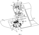
FIG. 1 is a first schematic structural diagram of a shell assembly according to an embodiment of this application; -
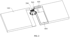
FIG. 2 is a second schematic structural diagram of a shell assembly according to an embodiment of this application; -
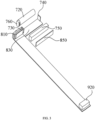
FIG. 3 is a schematic structural diagram of a driving assembly according to an embodiment of this application; -
FIG. 4 is a schematic structural diagram of a bracket and a slider according to an embodiment of this application; -
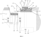
FIG. 5 is a partial schematic enlarged view of a shell assembly according to an embodiment of this application; -
FIG. 6 is a schematic structural diagram of a locking assembly according to an embodiment of this application; -
FIG. 7 is a schematic structural diagram of a fingerprint module according to an embodiment of this application; and -
FIG. 8 is a schematic structural diagram of a hinge and a driving motor according to an embodiment of this application; - The corresponding relationship between reference signs and part names in
FIG. 1 to FIG. 8 is as follows:
100. shell, 110. key cover, 200. hinge, 210. hinge body, 220. first connecting shaft, 230. first connecting portion, 240. second connecting shaft, 250. second connecting portion, 260. first gear, 270. second gear, 280. third gear, 300. linkage assembly, 310. first connecting rod, 320. second connecting rod, 330. pin, 400. locking assembly, 410. bracket, 412. bracket body, 414. first sliding groove, 416. second sliding groove, 418. guiding hole, 419. fixing post, 420. slider, 422. slider body, 424. first guiding surface, 430. elastic member, 440. ball, 500. third sliding groove, 600. locking key, 610. locking key body, 620. toggle portion, 630. second guiding surface, 710 driving assembly, 720. piezoelectric component, 730. first electrode, 740. second electrode, 750. power storage component, 760. clamping component, 770. clamping groove, 780. mounting groove, 800. main board, 810. fingerprint circuit board, 820. fingerprint module, 830. piezoelectric circuit board, 840. driving motor, 850. double-sided adhesive tape, 860. fingerprint protection cover, 870. fingerprint sensor, 880. fingerprint key, 910. fingerprint circuit pad, and 920. fingerprint circuit board connector. - To more clearly understand the foregoing purposes, features, and advantages in this application, the following describes further in detail this application with reference to the accompanying drawings and specific embodiments. It should be noted that, in absence of conflicts, the embodiments and features in the embodiments in this application may be mutually combined.
- The following description provides many specific details to facilitate a thorough understanding of this application. However, it should be noted that this application can be implemented in other ways different from those described herein. Therefore, the scope of protection of this application is not limited to the specific embodiments disclosed below.
- The following describes a shell assembly, a shell assembly control method, a shell assembly control system, an electronic device, and a storage medium according to some embodiments of this application with reference to
FIGs. 1 to 8 . - This embodiment provides a shell assembly, as shown in
FIGs. 1 to 8 , including: at least twoshells 100, ahinge 200, alinkage assembly 300, a lockingassembly 400, a lockingkey 600, and a drivingassembly 710. The at least twoshells 100 include a first shell. The at least twoshells 100 are connected through thehinge 200, and the at least twoshells 100 are able to rotate relative to thehinge 200. A first end of thelinkage assembly 300 is connected to thehinge 200, and a second end of thelinkage assembly 300 extends into the first shell and is movably connected to the first shell. The lockingassembly 400 is provided on the first shell and opposite the second end of thelinkage assembly 300, the lockingassembly 400 having a first state and a second state. In a case that the lockingassembly 400 is in the first state, the lockingassembly 400 is separated from the second end of thelinkage assembly 300; and in a case that the lockingassembly 400 is in the second state, the lockingassembly 400 abuts against the second end of thelinkage assembly 300. The lockingkey 600 is provided on the first shell and is in contact with the lockingassembly 400. The drivingassembly 710 is connected to the locking key 600 to drive, through the lockingkey 600, the lockingassembly 400 to switch between the first state and the second state. - In this embodiment, the shell assembly includes at least two
shells 100, ahinge 200, alinkage assembly 300, a lockingassembly 400, a lockingkey 600, and a drivingassembly 710. The lockingkey 600 is provided on the first shell and is in contact with the lockingassembly 400. The drivingassembly 710 is connected to the locking key 600 such that the drivingassembly 710 can drive the lockingkey 600, which in turn drives the lockingassembly 400 to switch between the first state and the second state. In a case that the lockingassembly 400 is in the first state, the lockingassembly 400 is separated from the second end of thelinkage assembly 300, and thehinge 200 is able to rotate; and in a case that the lockingassembly 400 is in the second state, the lockingassembly 400 abuts against the second end of thelinkage assembly 300. The second end of thelinkage assembly 300 is stationary relative to the first shell to fix thehinge 200. Through the controlling of the state of the lockingassembly 400, the purpose of locking and releasing thelinkage assembly 300 is achieved. Locking thelinkage assembly 300 stabilizes the opening angle of the first shell and in addition, thehinge 200 can be fixed through thelinkage assembly 300, enabling the first shell to stably maintain a specific opening angle. This ensures that the screen of the electronic device stably remains at an opening angle, enhancing the stability of theshell 100 during electronic device usage and improving the user experience of the electronic device. - Specifically, the shell assembly includes at least two
shells 100 and ahinge 200, and the at least twoshells 100 are connected through thehinge 200, thereby making the at least twoshells 100 rotatable relative to each other, and the at least twoshells 100 are also rotatable relative to thehinge 200. The shell assembly further includes alinkage assembly 300 and a lockingassembly 400. A first end of thelinkage assembly 300 is connected to thehinge 200, and a second end of thelinkage assembly 300 extends into the first shell and is movably connected to the first shell. The lockingassembly 400 is provided on the first shell and can switch between a first state and a second state. In a case that the lockingassembly 400 is in the first state, the lockingassembly 400 is separated from the second end of thelinkage assembly 300, and thehinge 200 rotates, allowing the second end of thelinkage assembly 300 to be movably connected to the first shell, enabling the first shell to freely rotate relative to thehinge 200. In a case that the lockingassembly 400 is in the second state, the lockingassembly 400 abuts against the second end of thelinkage assembly 300 and the second end of thelinkage assembly 300 remains stationary relative to the first shell to fix thehinge 200 and maintain a specific angle between the first shell and thehinge 200. The shell assembly further includes a drivingassembly 710, where the drivingassembly 710 is installed in the sliding groove on the inner surface of thekey cover 110 and is snap fitted at the corresponding position of theshell 100. The drivingassembly 710 is securely connected to the lockingkey 600. Through the application of an electric field to both ends of the drivingassembly 710, the drivingassembly 710 undergoes expansion or contraction deformation. This deformation drives the movement of the lockingkey 600, which in turn drives the lockingassembly 400 to switch between the first state and the second state. - Further, in the shell assembly provided in this application, the opening angle of the first shell can be limited through the
linkage assembly 300. In addition, the first shell can be more stably maintained at that opening angle through the fixing of thehinge 200 by thelinkage assembly 300. This ensures that the screen of the electronic device to be more stably maintained at that opening angle, enhancing the overall stability of the electronic device and improving the user experience of the electronic device. Furthermore, the state of the lockingassembly 400 can be manually controlled using the lockingkey 600; or the drivingassembly 710 can be used to drive the lockingkey 600, which in turn drives the lockingassembly 400 to electrically switch between states. This enhances flexibility in usage and improves the user experience. - This embodiment provides a shell assembly. In addition to the technical features of the foregoing embodiments, this embodiment further includes the following technical features.
- As shown in
FIGs. 1 to 8 , the drivingassembly 710 includes: apiezoelectric component 720, afirst electrode 730, asecond electrode 740, and apower storage component 750. A first end of thepiezoelectric component 720 is connected to the lockingkey 600. Thefirst electrode 730 is provided between the first end of thepiezoelectric component 720 and the lockingkey 600. Thesecond electrode 740 is provided at a second end of thepiezoelectric component 720. Two poles of thepower storage component 750 are respectively connected to thefirst electrode 730 and thesecond electrode 740. - In this embodiment, the driving
assembly 710 includes apiezoelectric component 720, afirst electrode 730, and asecond electrode 740. The first end of thepiezoelectric component 720 is connected to the lockingkey 600. Thefirst electrode 730 is provided between the first end of thepiezoelectric component 720 and the lockingkey 600. Thesecond electrode 740 is provided at the second end of thepiezoelectric component 720. The drivingassembly 710 further includes apower storage component 750. Thepower storage component 750 is adhered to thebracket 410 through a double-sidedadhesive tape 850 and two poles of thepower storage component 750 are respectively connected to thefirst electrode 730 and thesecond electrode 740. An electric field is applied to thefirst electrode 730 and thesecond electrode 740 through thepower storage component 750, such that the electric field is applied to two ends of thepiezoelectric component 720, causing thepiezoelectric component 720 to mechanically deform under the action of the inverse piezoelectric effect, driving the locking key 600 to move to a designated position, and consequently driving the lockingassembly 400 to move, thereby implementing the locking/unlocking function. Moreover, with thepower storage component 750 configured, thepiezoelectric component 720 can obtain stable driving power, thereby improving the operational stability and reliability of thepiezoelectric component 720. - Further, a positive or negative voltage is applied to two ends of the
piezoelectric component 720 by utilizing the inverse piezoelectric effect of thepiezoelectric component 720, such that thepiezoelectric component 720 is extended or compressed by a corresponding displacement amount, driving the locking key 600 to move to a designated position. As a result, the lockingassembly 400 is driven to move, implementing the locking/unlocking function. - Further, the inverse piezoelectric effect refers to the phenomenon that when an electric field is applied in the polarization direction of dielectrics, these dielectrics will generate mechanical deformation or mechanical stress in a certain direction, and when the applied electric field is removed, this deformation or stress will also disappear. Using this principle, an electric field can be applied to the
piezoelectric component 720 to make thepiezoelectric component 720 to generate a mechanical deformation, thereby generating a force to drive the locking key 600 to move and achieving the effect of driving the lockingassembly 400 to move. - Further, when the automatic locking/unlocking function of the folding screen is not used, the locking/unlocking action of the locking
assembly 400 can be implemented by manually manipulating the locking key 600 to drive the lockingassembly 400 to move. In this case, the piezoelectric effect of thepiezoelectric component 720 can be used to charge thepower storage component 750 and the battery of the mobile phone, thus realizing the conversion of mechanical energy to electric energy, improving the running time of thepiezoelectric component 720, and reducing the energy consumption of the mobile phone. - This embodiment provides a shell assembly. In addition to the technical features of the foregoing embodiments, this embodiment further includes the following technical features.
- As shown in
FIGs. 1 to 8 , the lockingassembly 400 further includes abracket 410 and aslider 420; where thebracket 410 is connected to the first shell; and theslider 420 is provided in thebracket 410 and is able to slide relative to thebracket 410, where the second end of thelinkage assembly 300 is threaded through thebracket 410; in a case that the lockingassembly 400 is in the first state, theslider 420 is in a second position and is separated from the second end of thelinkage assembly 300; and in a case that the lockingassembly 400 is in the second state, theslider 420 is in a first position and abuts against the second end of thelinkage assembly 300. - In this embodiment, in this technical solution, the
slider 420 is provided in thebracket 410 and is capable of sliding relative to thebracket 410. When theslider 420 slides to a first position of pressing against thelinkage assembly 300, thelinkage assembly 300 is fixed by theslider 420, and thelinkage assembly 300 can be used to support thehinge 200 and theshell 100 connected to thebracket 410, thereby allowing theshell 100 to be at a certain angle with thehinge 200. When theslider 420 slides to a second position away from thelinkage assembly 300, theslider 420 is not in contact with thelinkage assembly 300, and thelinkage assembly 300 is able to slide relative to thebracket 410, enabling theshell 100 connected to thebracket 410 to rotate freely relative to thehinge 200. - This embodiment provides a shell assembly. In addition to the technical features of the foregoing embodiments, this embodiment further includes the following technical features.
- As shown in
FIGs. 1 to 8 , thebracket 410 includes: abracket body 412, a first slidinggroove 414, a second slidinggroove 416, and a guidinghole 418; where the first slidinggroove 414 is provided on thebracket body 412, and thelinkage assembly 300 is threaded through the first slidinggroove 414; the second slidinggroove 416 is provided on thebracket body 412, communicatively connected to the first slidinggroove 414, and is perpendicular to the first slidinggroove 414, and theslider 420 is provided within the second slidinggroove 416; and the guidinghole 418 is provided on thebracket body 412, along the sliding direction of theslider 420. The lockingassembly 400 further includes anelastic member 430, where theelastic member 430 is provided within the guidinghole 418, with one end abutting against thebracket body 412 and another end abutting against theslider 420. - In this embodiment, the
bracket 410 includes abracket body 412, where thebracket body 412 is provided with a first slidinggroove 414 and a second slidinggroove 416, thelinkage assembly 300 is able to slide within the first slidinggroove 414 and theslider 420 is able to slide within the second slidinggroove 416. As the first slidinggroove 414 is communicatively connected to the second slidinggroove 416, theslider 420 can be in contact with thelinkage assembly 300, and thus the fixation of thelinkage assembly 300 can be realized by the friction between theslider 420 and thelinkage assembly 300, such that theshell 100 can be at a certain angle with thehinge 200. The guidinghole 418 is provided on thebracket body 412 and in the sliding direction of theslider 420. Anelastic member 430 is provided in the guidinghole 418, with one end abutting against thebracket body 412 and another end abutting against theslider 420, such that theslider 420 may move under the action of theelastic member 430, allowing theelastic member 430 to drive theslider 420 away from thelinkage assembly 300. As a result, theslider 420 can automatically slide to the second position when restriction on it is released, making it more convenient for the user to operate the lockingassembly 400. - Further, the sliding direction of the
slider 420 is perpendicular to the sliding direction of thelinkage assembly 300. - Further, the
elastic member 430 is a spring. When theslider 420 is in the first position, theelastic member 430 is in a compressed state. - Further, the
slider 420 is provided with a fixingpost 419, and theelastic member 430 is sleeved on the fixingpost 419 and is embedded in the guidinghole 418. - This embodiment provides a shell assembly. In addition to the technical features of the foregoing embodiments, this embodiment further includes the following technical features. As shown in
FIGs. 1 to 8 , theslider 420 includes aslider body 422 and aball 440, one side of theslider body 422 is able to abut against thelinkage assembly 300, and another side of theslider body 422 is provided with afirst guiding surface 424, thefirst guiding surface 424 being inclined relative to thelinkage assembly 300. - In this embodiment, the
first guiding surface 424 is provided on another side of theslider body 422 and is inclined relative to thelinkage assembly 300, therefore it is able to drive theslider 420 to move between the first position and the second position. - This embodiment provides a shell assembly. In addition to the technical features of the foregoing embodiments, this embodiment further includes the following technical features.
- As shown in
FIGs. 1 to 8 , the shell assembly further includes: a third slidinggroove 500, where the third slidinggroove 500 is provided on one of the at least twoshells 100, and the third slidinggroove 500 is provided from theslider 420 to outside of one of the at least twoshells 100 in a cut-through manner; where the lockingkey 600 is provided in the third slidinggroove 500 and is in contact with thefirst guiding surface 424, at least part of the locking key 600 protrudes from an outer wall of one of the at least twoshells 100, and thepiezoelectric component 720 is able to drive the locking key 600 to slide in the third slidinggroove 500, further driving theslider 420 to move between the first position and the second position. - In this embodiment, the locking
key 600 is provided within the third slidinggroove 500 and is in contact with thefirst guiding surface 424. Since thefirst guiding surface 424 is provided on another side of theslider body 422 and is inclined relative to thelinkage assembly 300, while the lockingkey 600 is sliding within the third slidinggroove 500, it is able to drive theslider 420 to move between the first position and the second position. Moreover, through the controlling of thepiezoelectric component 720 to drive the locking key 600 to slide in the third slidinggroove 500, the electrical control of the movement of the lockingkey 600 is achieved, thereby enabling the user to use the locking key 600 to control, through specific control action commands, theslider 420 to lock or move away from thelinkage assembly 300, enhancing the convenience of the lockingassembly 400 during use. In addition, at least a portion of the locking key 600 protrudes from the outer wall of one of the at least twoshells 100, which facilitates manual pushing of the lockingkey 600 by the user to implement manual adjustment of the position of theslider 420, providing users with a more flexible method for controlling the lockingassembly 400 and making it more convenient to use. - Further, through the utilization of the inverse piezoelectric effect of the
piezoelectric component 720 and control of the polarity of the electrodes, when a positive voltage is applied to thepiezoelectric component 720, thepiezoelectric component 720 elongates, and when a negative voltage is applied to thepiezoelectric component 720, thepiezoelectric component 720 contracts. This allows the movement of the locking key 600 to be driven by the length change of thepiezoelectric component 720, thereby driving the lockingassembly 400 to perform locking and unlocking actions. - Further, during manual control, after the user opens the
shell 100 to an opening angle, thelinkage assembly 300 moves to a corresponding position. When the user pushes the lockingkey 600, the lockingkey 600 pushes theslider 420 to move from the second position to the first position. Thus, thelinkage assembly 300 is locked through theslider 420, making theshell 100 maintained at the opening angle. When the user needs to rotate theshell 100 and pushes the lockingkey 600, the locking key 600 no longer restricts the position of theslider 420. Theslider 420 moves from the first position to the second position under the driving of theelastic member 430, releasing thelinkage assembly 300 and allowing theshell 100 to be freely rotated according to the need of the user. - This embodiment provides a shell assembly. In addition to the technical features of the foregoing embodiments, this embodiment further includes the following technical features.
- As shown in
FIGs. 1 to 8 , the lockingkey 600 includes a lockingkey body 610, atoggle portion 620, and asecond guiding surface 630, where thetoggle portion 620 is provided on a first side of the lockingkey body 610 and protrudes from the outer wall of one of the at least twoshells 100; and thesecond guiding surface 630 is provided on a second side of the lockingkey body 610 and matches thefirst guiding surface 424. - In this embodiment, the locking
key 600 includes the lockingkey body 610, thetoggle portion 620, and thesecond guiding surface 630. The user may push the lockingkey body 610 through thetoggle portion 620, thereby driving thesecond guiding surface 630 to move. Thesecond guiding surface 630 matches thefirst guiding surface 424, such that the lockingkey body 610 may drive thefirst guiding surface 424 through thesecond guiding surface 630, thereby realizing the driving of theslider 420. - This embodiment provides a shell assembly. In addition to the technical features of the foregoing embodiments, this embodiment further includes the following technical features.
- As shown in
FIGs. 1 to 8 , the drivingassembly 710 further includes aclamping component 760 and apiezoelectric circuit board 830, where theclamping component 760 is connected to the first end of thepiezoelectric component 720; the lockingkey body 610 is provided with a clampinggroove 770, and theclamping component 760 is clamped in the clampinggroove 770; and thepiezoelectric circuit board 830 is provided on thepiezoelectric component 720, and is electrically connected to thefingerprint circuit board 810. - In this embodiment, the driving
assembly 710 includes aclamping component 760, where theclamping component 760 is connected to the first end of thepiezoelectric component 720, and a clampinggroove 770 is provided on the lockingkey body 610, theclamping component 760 being clamped into the clampinggroove 770. In this application, one end of thepiezoelectric component 720 is connected to theclamping component 760, and theclamping component 760 is securely fixed to thepiezoelectric component 720 and moves with the telescoping action of thepiezoelectric component 720. Through the clamping of theclamping component 760 within the clampinggroove 770 provided on the lockingkey body 610, driving the movement of theclamping component 760 through the telescoping action of thepiezoelectric component 720 is implemented. The movement of theclamping component 760 then drives the movement of the lockingkey body 610, thereby realizing the effect of driving the lockingassembly 400 through the lockingkey 600 and realizing the locking/unlocking effect of the lockingassembly 400. The drivingassembly 710 further includes apiezoelectric circuit board 830, where thepiezoelectric circuit board 830 is provided on thepiezoelectric component 720, and is electrically connected to thefingerprint circuit board 810. Since thefingerprint circuit board 810 is electrically connected to themain board 800, electrically connecting thepiezoelectric circuit board 830 to thefingerprint circuit board 810 implements an electrical connection between thepiezoelectric circuit board 830 and themain board 800. This allows the locking and unlocking action command signals issued by themain board 800 to be transferred to thepiezoelectric circuit board 830 through thefingerprint circuit board 810, realizing the electric control of the drivingassembly 710. Furthermore, through this connection, the electric energy generated by thepiezoelectric component 720 through the piezoelectric effect can be transferred to the mobile phone battery, so as to implement charging of the mobile phone battery, improving the battery life of the mobile phone, and enhancing the user experience. - This embodiment provides a shell assembly. In addition to the technical features of the foregoing embodiments, this embodiment further includes the following technical features.
- As shown in
FIGs. 1 to 8 , thefirst electrode 730 is provided in the clampinggroove 770 and located between the clampingcomponent 760 and the lockingkey body 610. - In this embodiment, the
first electrode 730 is provided in the clampinggroove 770 and located between the clampingcomponent 760 and the lockingkey body 610. Since theclamping component 760 is securely connected to thepiezoelectric component 720, the electrical energy can be transferred to theclamping component 760 through thefirst electrode 730, and then the electrical energy can be transferred to one end of thepiezoelectric component 720 through theclamping component 760, realizing the effect of applying voltage to that end of thepiezoelectric component 720. - This embodiment provides a shell assembly. In addition to the technical features of the foregoing embodiments, this embodiment further includes the following technical features.
- As shown in
FIGs. 1 and7 , the lockingkey body 610 is provided with a mountinggroove 780, and the locking key 600 further includes afingerprint circuit board 810 and afingerprint module 820; where thefingerprint circuit board 810 is provided in the mountinggroove 780; and thefingerprint module 820 is provided at thetoggle portion 620 and corresponds to thefingerprint circuit board 810. - In this embodiment, the locking key 600 further includes the
fingerprint circuit board 810 and thefingerprint module 820, and the lockingkey body 610 is provided with the mountinggroove 780. Thefingerprint circuit board 810 can be adhered into the mountinggroove 780 on the lockingkey body 610, and thefingerprint module 820 is provided at thetoggle portion 620 and corresponds to thefingerprint circuit board 810. Through thefingerprint module 820, a scanning and collection of the user fingerprint information is implemented. The collected data is transferred to the processor through thefingerprint circuit board 810, realizing the identification of the user information through the fingerprint information, and improving the security of the device. Furthermore, providing thefingerprint circuit board 810 and thefingerprint module 820 on the lockingkey 600 eliminates the need to set up a separate area for arranging thefingerprint module 820. This simplifies the design complexity, improves the overall aesthetics, enhances user convenience, and improves the user experience. - Further, the
fingerprint module 820 includes afingerprint protection cover 860, afingerprint sensor 870, a fingerprint key (fingerprint DOME key) 880, and afingerprint circuit pad 910. Thefingerprint protection cover 860 protects thefingerprint module 820 from being damaged. Thefingerprint sensor 870 is welded to the lockingkey 600, and thefingerprint sensor 870 acquires the capacitance value variations of the user fingerprints to implement scanning and identification of the fingerprint data of the user. Thefingerprint circuit board 810 is connected to themain board 800, which is installed on the first shell, through a fingerprintcircuit board connector 920. This allows the collected data to be transferred to a processor to implement recognition of the fingerprint data of the user. - This embodiment provides a shell assembly. In addition to the technical features of the foregoing embodiments, this embodiment further includes the following technical features.
- As shown in
FIGs. 1 to 8 , thelinkage assembly 300 includes a first connectingrod 310 and a second connectingrod 320; where one end of the first connectingrod 310 is rotationally connected to thehinge 200; and the second connectingrod 320 is rotationally connected to another end of the first connectingrod 310 and threaded through thebracket 410. - In this embodiment, one end of the first connecting
rod 310 is rotationally connected to thehinge 200; and the second connectingrod 320 is rotationally connected to another end of the first connectingrod 310, making thelinkage assembly 300 more flexible when theshell 100 is being opened or closed, and preventing thelinkage assembly 300 from affecting the opening or closing of theshell 100. - Further, the first connecting
rod 310 and the second connectingrod 320 are connected through apin 330 and are rotatable around thepin 330. - Further, the first connecting
rod 310 and the second connectingrod 320 are cylindrical in shape, and the side of theslider 420 in contact with the second connectingrod 320 is a curved surface, which matches the second connectingrod 320. - This embodiment provides a shell assembly. In addition to the technical features of the foregoing embodiments, this embodiment further includes the following technical features.
- As shown in
FIGs. 2 and8 , thehinge 200 includes ahinge body 210, a first connectingshaft 220, a first connectingportion 230, a second connectingshaft 240, a second connectingportion 250, afirst gear 260, asecond gear 270, a plurality ofthird gears 280, and a drivingmotor 840. The first connectingshaft 220 is threaded through thehinge body 210 and is located at one side of thehinge body 210. The first connectingportion 230 is sleeved on the first connectingshaft 220 and is connected to one of the at least twoshells 100. The second connectingshaft 240 is threaded through thehinge body 210 and is located at another side of thehinge body 210. The second connectingportion 250 is sleeved on the second connectingshaft 240 and is connected to another one of the at least twoshells 100. Thefirst gear 260 is connected to the first connectingshaft 220. Thesecond gear 270 is connected to the second connectingshaft 240. The plurality ofthird gears 280 are each engaged with thefirst gear 260 and thesecond gear 270. The drivingmotor 840 is connected to one of the plurality ofthird gears 280. Thelinkage assembly 300 is rotationally connected to one of the plurality ofthird gears 280. - Further, the driving
motor 840 is connected to the first connectingrod 310 and can drive the first connectingrod 310 to perform circular motion and the second connectingrod 320 to perform linear motion within the sliding groove. Thelinkage assembly 300 drives the movement of thehinge 200 and further drives the rotation of theshell 100. - In this embodiment, in this technical solution, the
hinge 200 is connected to the at least twoshells 100 via the first connectingshaft 220 and the second connectingshaft 240, respectively, enabling the at least twoshells 100 to rotate more flexibly, which in turn makes it more convenient for the user to use the electronic device. Through the utilization of thefirst gear 260, thesecond gear 270, and the plurality ofthird gears 280, thefirst gear 260 is engaged with one of the plurality ofthird gears 280, the plurality ofthird gears 280 are engaged in turn, and then anotherthird gear 280 in the plurality ofthird gears 280 is engaged with thesecond gear 270, enabling thefirst gear 260, thesecond gear 270, and the plurality ofthird gears 280 to rotate synchronously. Thefirst gear 260 is connected to the first connectingshaft 220 and thesecond gear 270 is connected to the second connectingshaft 240, enabling the first connectingshaft 220 and the second connectingshaft 240 to rotate synchronously, which in turn enables the at least twoshells 100 to rotate synchronously. The connection assembly can limit the opening angle between theshell 100 and thehinge 200, and the at least twoshells 100 can rotate synchronously. Therefore, the connection assembly can limit the opening angle of the at least twoshells 100, further enhancing the stability of theshell 100 after opening. In addition, the drivingmotor 840 is configured as connecting to one of the plurality ofthird gears 280 such that the drivingmotor 840 can drive the rotation of one of the plurality ofthird gears 280, thereby driving the rotation of thefirst gear 260 and thesecond gear 270, which in turn drives the rotation of thehinge 200. This achieves the electric opening and closing of theshells 100 on both sides, improving the convenience of the user during use and user experience. - Further, the first connecting
portion 230 and the second connectingportion 250 are connected to theshell 100 by screws. - Further, the plurality of
third gears 280 are in an even number to ensure that thefirst gear 260 and thesecond gear 270 rotate in the same direction. - An embodiment of this application further provides a shell assembly control method, including: controlling, based on operation information of a locking
key 600, a drivingassembly 710 to drive a lockingassembly 400 to switch to a first state; controlling at least twoshells 100 to move to a position corresponding to the operation information; and controlling the drivingassembly 710 to drive the lockingassembly 400 to switch to a second state. - In this embodiment, the shell assembly is provided with a driving
assembly 710, and the drivingassembly 710 is connected to the lockingkey 600. The drivingassembly 710 can be controlled, based on the operation information of the lockingkey 600, to drive the lockingkey 600, which in turn drives the lockingassembly 400 to switch between the first state and the second state, realizing electrical control of the state of the lockingassembly 400. In this application, the state of the lockingassembly 400 can be manually controlled using the lockingkey 600; or the drivingassembly 710 can be used to drive the lockingkey 600, which in turn drives the lockingassembly 400 to switch between states. This enhances flexibility in usage and improves the user experience on the electronic device. - Further, the locking
assembly 400 is provided on theshell 100 and can switch between a first state and a second state. In a case that the lockingassembly 400 is in the first state, theshell 100 can freely rotate relative to thehinge 200. The shell assembly further includes a lockingkey 600, and the lockingkey 600 is provided on theshell 100 and in contact with the lockingassembly 400. The locking key is configured to control the movement of the lockingassembly 400, implementing control over the state of the lockingassembly 400. In a case that the lockingassembly 400 is in the second state, the lockingassembly 400 abuts against the second end of thelinkage assembly 300 and the second end of thelinkage assembly 300 remains stationary relative to the first shell to fix thehinge 200 and maintain a specific angle between the first shell and thehinge 200. - This embodiment provides a shell assembly control method. In addition to the technical features of the foregoing embodiments, this embodiment further includes the following technical features.
- The operation information includes a number of times that the locking
key 600 is pressed, a position of the lockingkey 600, a movement state of the lockingkey 600, and/or a movement direction of the lockingkey 600. - In this embodiment, the operation information includes the number of times that the locking
key 600 is pressed, the position of the lockingkey 600, and the movement state or movement direction of the lockingkey 600. The control system can control the drivingassembly 710 to drive the lockingassembly 400 to switch between the first state and the second state based on the operation information of the lockingkey 600. This enables automatic switching of the state of thelocking component 400 through specific action control commands, enhancing use convenience and improving the user experience. - Further, the operation information may include a single-click, a double-click, a triple-click, or other pressing actions on the locking
key 600; or may be sliding the locking key 600 to a specific position or sliding the locking key 600 to a specific direction. - An embodiment of this application further provides a shell assembly control system, including a first switching unit, a control unit, and a second switching unit. The control system is configured to, based on operation information of a locking
key 600, control a drivingassembly 710 to drive a lockingassembly 400 to switch to a first state; control at least twoshells 100 to move to a position corresponding to the operation information; and control the drivingassembly 710 to drive the lockingassembly 400 to switch to a second state. - In this embodiment, the shell assembly control system includes the first switching unit, the control unit, and the second switching unit. The shell assembly is provided with a driving
assembly 710, and the drivingassembly 710 is connected to the lockingkey 600. The drivingassembly 710 can be controlled, based on the operation information of the lockingkey 600, to drive the lockingkey 600, which in turn drives the lockingassembly 400 to switch between the first state and the second state, realizing electrical control of the state of the lockingassembly 400. In this application, the state of the lockingassembly 400 can be manually controlled using the lockingkey 600; or the drivingassembly 710 can be used to drive the lockingkey 600, which in turn drives the lockingassembly 400 to switch between states. This enhances flexibility in usage and improves the user experience on the electronic device. - Further, the locking
assembly 400 is provided on theshell 100 and can switch between a first state and a second state. In a case that the lockingassembly 400 is in the first state, theshell 100 can freely rotate relative to thehinge 200. The shell assembly further includes a lockingkey 600, and the lockingkey 600 is provided on theshell 100 and in contact with the lockingassembly 400. The locking key is configured to control the movement of the lockingassembly 400, implementing control over the state of the lockingassembly 400. In a case that the lockingassembly 400 is in the second state, the lockingassembly 400 abuts against the second end of thelinkage assembly 300 and the second end of thelinkage assembly 300 remains stationary relative to the first shell to fix thehinge 200 and maintain a specific angle between the first shell and thehinge 200. - An embodiment of this application further provides an electronic device. The electronic device includes the shell assembly according to any one of the foregoing embodiments; or the electronic device includes a memory and a processor, where the memory is configured to store executable instructions, and the processor is configured to execute stored instructions to implement the steps of the shell assembly control method according to any one of the foregoing embodiments.
- In this embodiment, the electronic device provided in this application has all the beneficial effects of the shell assembly of any one of the foregoing embodiments as it includes the shell assembly. Details are not described herein again. Alternatively, the electronic device includes a memory and a processor, where the processor is capable of executing the instructions stored in the memory to implement the steps of the shell assembly control method of any one of the foregoing embodiments, and therefore has all the beneficial effects of the shell assembly control method. Details are not described herein again.
- An embodiment of this invention further provides an electronic device, configured to perform each process of the foregoing shell assembly control method embodiment, with the same technical effects achieved. To avoid repetition, details are not described herein.
- An embodiment of this application further provides a storage medium, where a computer program is stored and when the computer program is executed by a processor, the steps of the shell assembly control method according to any one of the foregoing embodiments are implemented.
- In this embodiment, the storage medium provided in this application is stored with a computer program and when the computer program is executed by a processor, the steps of the shell assembly control method according to any one of the foregoing embodiments are implemented. Therefore, the storage medium has all the beneficial effects of the shell assembly control method. Details are not described herein again.
- An embodiment of this invention further provides a computer program product, and the computer program product may be executed by a processor to implement each process of the foregoing shell assembly control method embodiment, with the same technical effects achieved. To avoid repetition, details are not described herein.
- In addition, an embodiment of this application provides a chip. The chip includes a processor and a communication interface. The communication interface is coupled to the processor. The processor is configured to run a program or instructions to implement each process of the foregoing shell assembly control method, with the same technical effect achieved. To avoid repetition, details are not described herein again.
- In the claims, specification, and accompanying drawings of the specification of this application, the term "a plurality of" means two or more than two. Unless otherwise defined explicitly, the orientations or positional relationships indicated by the term "up" or "down" are based on the orientations or positional relationships as shown in the accompanying drawings. These terms are merely for ease and brevity of description of the embodiments of this application rather than indicating or implying that the apparatuses or components mentioned must have specific orientations as described or must be constructed or manipulated according to specific orientations, and therefore shall not be construed as any limitations on the embodiments of this application. The terms "connection", "mounting", and "fixing" should be understood in their general senses. For example, the "connection" may be a fixed connection between a plurality of objects, a detachable connection between a plurality of objects, or an integrated connection; or a direct connection between a plurality of objects, or an indirect connection between a plurality of objects through an intermediate medium. Persons of ordinary skill in the art can understand specific meanings of these terms in this application based on the specific context of the foregoing data.
- In the claims, specification, and drawings of the specification of this application, descriptions of the terms "an embodiment", "some embodiments", or "a specific embodiment" mean the specific features, structures, materials or characteristics described with reference to the embodiment or example are included in at least one embodiment or example of this application. In the claims, specification, and drawings of the specification of this application, illustrative expressions of these terms do not necessarily refer to the same embodiment or example. Moreover, the specific features, structures, materials, or characteristics described may be combined in any suitable manners in any one or more embodiments or examples.
- The above described are only preferred embodiments of this application that are not intended to limit this application. For those skilled in the art, this application may have various changes and variations. Any modification, equivalent replacement, or improvement made without departing from the spirit and principle of this application shall fall within the protection scope of this application.
Claims (18)
- A shell assembly, comprising:at least two shells, wherein the at least two shells comprise a first shell;a hinge, wherein the at least two shells are connected through the hinge, and the at least two shells are able to rotate relative to the hinge;a linkage assembly, wherein a first end of the linkage assembly is connected to the hinge, and a second end of the linkage assembly extends into the first shell and is movably connected to the first shell;a locking assembly, wherein the locking assembly is provided on the first shell and opposite the second end of the linkage assembly, the locking assembly having a first state and a second state, whereinin a case that the locking assembly is in the first state, the locking assembly is separated from the second end of the linkage assembly; and in a case that the locking assembly is in the second state, the locking assembly abuts against the second end of the linkage assembly;a locking key, wherein the locking key is provided on the first shell and is in contact with the locking assembly; anda driving assembly, wherein the driving assembly is connected to the locking key to drive, through the locking key, the locking assembly to switch between the first state and the second state.
- The shell assembly according to claim 1, wherein the driving assembly comprises:a piezoelectric component, wherein a first end of the piezoelectric component is connected to the locking key;a first electrode, wherein the first electrode is provided between the first end of the piezoelectric component and the locking key; anda second electrode, wherein the second electrode is provided at a second end of the piezoelectric component.
- The shell assembly according to claim 2, wherein the driving assembly comprises:
a power storage component, wherein two poles of the power storage component are respectively connected to the first electrode and the second electrode. - The shell assembly according to claim 2, wherein the locking assembly further comprises:a bracket, wherein the bracket is connected to the first shell; anda slider, wherein the slider is provided in the bracket and is able to slide relative to the bracket; whereinthe second end of the linkage assembly is threaded through the bracket;in a case that the locking assembly is in the first state, the slider is in a second position and is separated from the second end of the linkage assembly; andin a case that the locking assembly is in the second state, the slider is in a first position and abuts against the second end of the linkage assembly.
- The shell assembly according to claim 4, wherein
the slider comprises a slider body, one side of the slider body is able to abut against the linkage assembly, and another side of the slider body is provided with a first guiding surface, the first guiding surface being inclined relative to the linkage assembly. - The shell assembly according to claim 5, wherein the shell assembly further comprises:a third sliding groove, wherein the third sliding groove is provided on one of the at least two shells, and the third sliding groove is provided from the slider to outside of one of the at least two shells in a cut-through manner; whereinthe locking key is provided in the third sliding groove and is in contact with the first guiding surface, at least part of the locking key protrudes from an outer wall of one of the at least two shells, and the piezoelectric component is able to drive the locking key to slide in the third sliding groove, so as to drive the slider to move between the first position and the second position.
- The shell assembly according to claim 6, wherein the locking key comprises:a locking key body;a toggle portion, wherein the toggle portion is provided at a first side of the locking key body and protrudes from the outer wall of one of the at least two shells; anda second guiding surface, wherein the second guiding surface is provided on a second side of the locking key body and matches the first guiding surface.
- The shell assembly according to claim 7, wherein the driving assembly further comprises:a clamping component, the clamping component being connected to the first end of the piezoelectric component; whereinthe locking key body is provided with a clamping groove, and the clamping component is clamped in the clamping groove; andthe first electrode is provided in the clamping groove and located between the clamping component and the locking key body.
- The shell assembly according to claim 7, wherein the locking key body is provided with a mounting groove and the locking key further comprises:a fingerprint circuit board, wherein the fingerprint circuit board is provided in the mounting groove; anda fingerprint module, wherein the fingerprint module is provided at the toggle portion and corresponds to the fingerprint circuit board.
- The shell assembly according to claim 9, wherein the driving assembly further comprises:
a piezoelectric circuit board, wherein the piezoelectric circuit board is provided on the piezoelectric component and is electrically connected to the fingerprint circuit board. - The shell assembly according to any one of claims 1 to 10, wherein the hinge comprises:a hinge body;a first connecting shaft, wherein the first connecting shaft is threaded through the hinge body and is located at one side of the hinge body;a first connecting portion, wherein the first connecting portion is sleeved on the first connecting shaft and is connected to one of the at least two shells;a second connecting shaft, wherein the second connecting shaft is threaded through the hinge body and is located at another side of the hinge body; anda second connecting portion, wherein the second connecting portion fits onto the second connecting shaft and is connected to another of the at least two shells.
- The shell assembly according to claim 11, wherein the hinge further comprises:a first gear, wherein the first gear is connected to the first connecting shaft;a second gear, wherein the second gear is connected to the second connecting shaft;a plurality of third gears, wherein the plurality of third gears are each engaged with the first gear and the second gear; anda driving motor, wherein the driving motor is connected to one of the plurality of third gears; andthe linkage assembly is rotationally connected to one of the plurality of third gears.
- A shell assembly control method, comprising:controlling, based on operation information of a locking key, a driving assembly to drive a locking assembly to switch to a first state;controlling at least two shells to move to a position corresponding to the operation information; andcontrolling the driving assembly to drive the locking assembly to switch to a second state.
- A shell assembly control system, comprising:a first switching unit, configured to control, based on operation information of a locking key, a driving assembly to drive a locking assembly to switch to a first state;a control unit, configured to control at least two shells to move to a position corresponding to the operation information; anda second switching unit, configured to control the driving assembly to drive the locking assembly to switch to a second state.
- An electronic device, whereinthe electronic device comprises the shell assembly according to any one of claims 1 to 12; orthe electronic device comprises a memory and a processor, wherein the memory is configured to store executable instructions, and the processor is configured to execute stored instructions to implement the steps of the shell assembly control method according to claim 13.
- An electronic device, configured to perform the steps of the shell assembly control method according to claim 13.
- A readable storage medium, wherein the readable storage medium stores a program or instructions, and when the program or instructions are executed by a processor, the steps of the shell assembly control method according to claim 13 are implemented.
- A computer program product, wherein the computer program product is able to be executed by a processor to implement the steps of the shell assembly control method according to claim 13.
Applications Claiming Priority (2)
| Application Number | Priority Date | Filing Date | Title |
|---|---|---|---|
| CN202111197711.9A CN113923283B (en) | 2021-10-14 | 2021-10-14 | Shell assembly, control method and system, and electronic device |
| PCT/CN2022/123923 WO2023061268A1 (en) | 2021-10-14 | 2022-10-08 | Housing assembly, control method and system, and electronic device |
Publications (2)
| Publication Number | Publication Date |
|---|---|
| EP4418637A1 true EP4418637A1 (en) | 2024-08-21 |
| EP4418637A4 EP4418637A4 (en) | 2025-01-22 |
Family
ID=79240411
Family Applications (1)
| Application Number | Title | Priority Date | Filing Date |
|---|---|---|---|
| EP22880207.0A Pending EP4418637A4 (en) | 2021-10-14 | 2022-10-08 | HOUSING ARRANGEMENT, CONTROL METHOD AND SYSTEM AND ELECTRONIC DEVICE |
Country Status (4)
| Country | Link |
|---|---|
| US (1) | US20240259484A1 (en) |
| EP (1) | EP4418637A4 (en) |
| CN (1) | CN113923283B (en) |
| WO (1) | WO2023061268A1 (en) |
Families Citing this family (7)
| Publication number | Priority date | Publication date | Assignee | Title |
|---|---|---|---|---|
| CN113923283B (en) * | 2021-10-14 | 2024-08-23 | 维沃移动通信有限公司 | Shell assembly, control method and system, and electronic device |
| CN114928668B (en) * | 2022-05-18 | 2024-12-20 | 维沃移动通信有限公司 | Electronic equipment |
| CN115551250B (en) * | 2022-09-19 | 2025-09-16 | 维沃移动通信有限公司 | electronic devices |
| CN115681313B (en) * | 2022-11-03 | 2026-01-23 | 维沃移动通信有限公司 | Electronic equipment |
| CN116980508B (en) * | 2023-06-29 | 2024-04-05 | 荣耀终端有限公司 | Locking mechanism and foldable electronic device |
| CN117404633B (en) * | 2023-11-08 | 2024-07-19 | 惠州市沃生照明有限公司 | Rigidity-changeable desk lamp capable of being stored |
| CN118571126B (en) * | 2024-07-31 | 2024-12-27 | 荣耀终端有限公司 | Folding screen assembly, electronic device and control method |
Family Cites Families (12)
| Publication number | Priority date | Publication date | Assignee | Title |
|---|---|---|---|---|
| CN106527585A (en) * | 2016-11-02 | 2017-03-22 | 上海天马微电子有限公司 | Foldable flexible display |
| WO2019173940A1 (en) * | 2018-03-12 | 2019-09-19 | 深圳市柔宇科技有限公司 | Bending assembly and flexible display device |
| CN112291395B (en) * | 2020-10-30 | 2022-05-17 | 维沃移动通信有限公司 | Electronic equipment and control method |
| CN112540650A (en) * | 2020-12-09 | 2021-03-23 | 维沃移动通信有限公司 | Electronic device |
| CN112797068A (en) * | 2021-01-20 | 2021-05-14 | 维沃移动通信有限公司 | Rotating structure and electronic equipment |
| CN112887460B (en) * | 2021-01-22 | 2023-05-23 | 维沃移动通信有限公司 | Folding mechanism and electronic equipment |
| CN113179341B (en) * | 2021-04-29 | 2023-09-22 | 维沃移动通信有限公司 | Electronic equipment, button control method and device |
| CN113422851B (en) * | 2021-06-18 | 2025-01-10 | Oppo广东移动通信有限公司 | An electronic device |
| CN113438349B (en) * | 2021-06-25 | 2024-03-29 | 维沃移动通信有限公司 | Electronic equipment, control method and control device thereof |
| CN113411439B (en) * | 2021-06-25 | 2024-03-29 | 维沃移动通信有限公司 | Electronic equipment, control method and control device thereof |
| CN113790209B (en) * | 2021-09-01 | 2022-11-01 | 维沃移动通信有限公司 | Shell assembly and electronic equipment |
| CN113923283B (en) * | 2021-10-14 | 2024-08-23 | 维沃移动通信有限公司 | Shell assembly, control method and system, and electronic device |
-
2021
- 2021-10-14 CN CN202111197711.9A patent/CN113923283B/en active Active
-
2022
- 2022-10-08 WO PCT/CN2022/123923 patent/WO2023061268A1/en not_active Ceased
- 2022-10-08 EP EP22880207.0A patent/EP4418637A4/en active Pending
-
2024
- 2024-04-12 US US18/633,822 patent/US20240259484A1/en active Pending
Also Published As
| Publication number | Publication date |
|---|---|
| CN113923283A (en) | 2022-01-11 |
| WO2023061268A1 (en) | 2023-04-20 |
| CN113923283B (en) | 2024-08-23 |
| US20240259484A1 (en) | 2024-08-01 |
| EP4418637A4 (en) | 2025-01-22 |
Similar Documents
| Publication | Publication Date | Title |
|---|---|---|
| US20240259484A1 (en) | Housing Assembly, Control Method and Electronic Device | |
| CN114598759B (en) | electronic devices | |
| TWI284268B (en) | Input device provided with windable display and foldable keyboard, and personal computer provided with input device | |
| CN112291395B (en) | Electronic equipment and control method | |
| CN216812500U (en) | Hinge structure and electronic equipment | |
| WO2021121118A1 (en) | Electronic device | |
| CN111459228A (en) | Electronic equipment and opening and closing method thereof | |
| CN109313467A (en) | a mobile terminal | |
| WO2024159757A1 (en) | Rotary shaft mechanism and electronic device | |
| CN112558696A (en) | Electronic device | |
| CN208225017U (en) | Portable input device | |
| CN106125844A (en) | A kind of electronic equipment and open-and-close mechanism thereof | |
| WO2022088936A1 (en) | Power adapter and electronic device assembly | |
| CN108536226A (en) | A kind of laptop | |
| CN208386646U (en) | Electronic equipment | |
| CN103596397A (en) | Switch mechanism and portable electronic device thereof | |
| TW202127176A (en) | Portable electronic device | |
| CN117135240A (en) | Folding components and folding devices | |
| WO2023226982A1 (en) | Electronic device | |
| CN109962995B (en) | Functional assembly, electronic device and control method thereof | |
| CN223566212U (en) | Learning apparatus | |
| CN223347420U (en) | Learning equipment | |
| CN119277693B (en) | Electronic equipment | |
| CN118655957B (en) | A keyboard assembly and an electronic device | |
| CN216647248U (en) | Notebook computer with movable rotary camera |
Legal Events
| Date | Code | Title | Description |
|---|---|---|---|
| STAA | Information on the status of an ep patent application or granted ep patent |
Free format text: STATUS: THE INTERNATIONAL PUBLICATION HAS BEEN MADE |
|
| PUAI | Public reference made under article 153(3) epc to a published international application that has entered the european phase |
Free format text: ORIGINAL CODE: 0009012 |
|
| STAA | Information on the status of an ep patent application or granted ep patent |
Free format text: STATUS: REQUEST FOR EXAMINATION WAS MADE |
|
| 17P | Request for examination filed |
Effective date: 20240425 |
|
| AK | Designated contracting states |
Kind code of ref document: A1 Designated state(s): AL AT BE BG CH CY CZ DE DK EE ES FI FR GB GR HR HU IE IS IT LI LT LU LV MC ME MK MT NL NO PL PT RO RS SE SI SK SM TR |
|
| A4 | Supplementary search report drawn up and despatched |
Effective date: 20241220 |
|
| DAV | Request for validation of the european patent (deleted) | ||
| DAX | Request for extension of the european patent (deleted) | ||
| RIC1 | Information provided on ipc code assigned before grant |
Ipc: G06F 1/16 20060101ALI20241216BHEP Ipc: H04M 1/02 20060101AFI20241216BHEP |