EP4418625B1 - Nachrichtenleitweglenkungssystem - Google Patents
Nachrichtenleitweglenkungssystem Download PDFInfo
- Publication number
- EP4418625B1 EP4418625B1 EP23157649.7A EP23157649A EP4418625B1 EP 4418625 B1 EP4418625 B1 EP 4418625B1 EP 23157649 A EP23157649 A EP 23157649A EP 4418625 B1 EP4418625 B1 EP 4418625B1
- Authority
- EP
- European Patent Office
- Prior art keywords
- message
- data streaming
- streaming application
- module
- routing
- Prior art date
- Legal status (The legal status is an assumption and is not a legal conclusion. Google has not performed a legal analysis and makes no representation as to the accuracy of the status listed.)
- Active
Links
Images




Classifications
-
- H—ELECTRICITY
- H04—ELECTRIC COMMUNICATION TECHNIQUE
- H04L—TRANSMISSION OF DIGITAL INFORMATION, e.g. TELEGRAPHIC COMMUNICATION
- H04L45/00—Routing or path finding of packets in data switching networks
- H04L45/302—Route determination based on requested QoS
- H04L45/306—Route determination based on the nature of the carried application
-
- H—ELECTRICITY
- H04—ELECTRIC COMMUNICATION TECHNIQUE
- H04L—TRANSMISSION OF DIGITAL INFORMATION, e.g. TELEGRAPHIC COMMUNICATION
- H04L51/00—User-to-user messaging in packet-switching networks, transmitted according to store-and-forward or real-time protocols, e.g. e-mail
- H04L51/21—Monitoring or handling of messages
- H04L51/23—Reliability checks, e.g. acknowledgments or fault reporting
-
- H—ELECTRICITY
- H04—ELECTRIC COMMUNICATION TECHNIQUE
- H04L—TRANSMISSION OF DIGITAL INFORMATION, e.g. TELEGRAPHIC COMMUNICATION
- H04L45/00—Routing or path finding of packets in data switching networks
- H04L45/38—Flow based routing
Definitions
- the present invention relates to the field of message routing, in particular routing of content messages between data streaming applications using a message routing system.
- data streaming services which are also known as “messaging systems” or “messaging platforms”
- messages systems such as Amazon Managed Kafka and Amazon Kinesis
- Amazon Managed Kafka and Amazon Kinesis could differ from one team to another on the basis of use cases, expertise, scalability, etc.
- these data streaming services need to have some mode of interaction established which takes away the complexity around data formats and communication protocols and enable messages to be read reliably.
- system A with Amazon Web Services (AWS) Managed Kafka as its choice of data streaming service
- system B with Amazon Kinesis as its choice of data streaming service.
- AWS Amazon Web Services
- system B would have to include specific capabilities that are purposed for reading data from the data streaming service implemented by system A - these may conflict with the agreed technical preferences of system B.
- system A may not be able to publish events to system B as it is not its responsibility.
- a message routing system comprises: a message routing module, a routing configuration module, a first binder module, a second binder module.
- the routing configuration module is configured to provide a routing configuration for each of one or more content messages, each routing configuration comprising a source of the respective content message and one or more targets for the respective content message, each of the source and the one or more targets being characterised by a channel and an address.
- the first binder module is configured to connect a first data streaming application to the message routing module using one or more channels, and to enable a content message to be routed to and/or from the first data streaming application.
- the second binder module is configured to connect a second data streaming application to the message routing module using one or more channels, and to enable a content message to be routed to and/or from the second data streaming application.
- the first data streaming application is associated with a first cloud-based account and the second data streaming application is associated with a second cloud-based account.
- the message routing module configured to: receive a content message from a data streaming application and a corresponding routing configuration for the content message from the routing configuration module, and route the content message according to the corresponding routing configuration using a stream bridge interface.
- the message routing system enables data streaming applications to interact with each other in a dynamic manner without requiring specific adapters to be built for the data streaming applications.
- the message routing system improves the interoperability of data streaming applications and makes it easier for organisations to integrate cross-account event interaction between systems.
- the use of routing configurations allows content messages to be routed between data streaming applications in a configurable and flexible way.
- an address characterising a source or a target may designate a content message stream at a corresponding data streaming application.
- the address contained in a routing configuration can specify a particular content stream at a respective data streaming application from which a content message is to be routed or to which a content message is to be routed.
- the message routing module may be further configured to: determine that the content message has been delivered; and upon determining that the content message has been delivered, send an acknowledgement to the respective data streaming application specified as the source in the corresponding routing configuration, so as to trigger data offset to be committed with respect to the delivered content message at the respective data streaming application.
- the message routing system can minimise data loss by ensuring data offset is only committed upon successful delivery of the content message.
- the first data streaming application may be selected from a list including: Amazon Managed Streaming for AWS Managed Kafka, Amazon Kinesis, Rabbit MQ, Amazon Simple Notification Service, Amazon Simple Queue Service, and Apache RocketMQ, and the second data streaming application may be another data streaming application selected from the list.
- the message routing system may be deployed on a consumer domain.
- a consumer on the consumer domain is provided with the capability to read content messages from a producer system.
- the message routing system may further comprise a secrets manager module configured to rotate one or more secrets associated with at least one of the first and second data streaming applications based on a predetermined configuration.
- the message routing system can reduce the risk of unauthorised access to the data streaming applications and ensure that data streaming applications are using the most current credentials
- At least one of the first and second binder modules may comprise a health endpoint configured to: acquire one or more health status parameters of the respective data streaming application, wherein the one or more health status parameters comprises a secrets rotation parameter indicating whether a secret associated with the respective data streaming application is rotated; and restart the respective data streaming application if at least one of one or more health status parameters does not meet a predetermined criterion.
- the message routing system can ensure that respective data streaming applications are functioning properly and that issues (e.g. relating to secrets management) that may affect the performance or stability of the data streaming applications are minimised.
- the message routing module may be configured to receive the content message by pulling the content message from the respective data streaming application.
- the message routing system can ensure that the content messages to be routed from a respective data streaming application are properly retrieved from said data streaming application.
- the routing configuration for a content message may comprise a source of the respective content message and a plurality of targets for the respective content message.
- the message routing system provides the capability of allowing a content message to be routed to multiple targets (e.g. multiple content message streams).
- the message routing system may further comprise a metrics monitoring module configured to determine at least one of a number of content messages received from one of the first data streaming application and the second data streaming application that have been successfully delivered and a number of content messages received from one of the first data streaming application and the second data streaming application that failed to be delivered.
- a metrics monitoring module configured to determine at least one of a number of content messages received from one of the first data streaming application and the second data streaming application that have been successfully delivered and a number of content messages received from one of the first data streaming application and the second data streaming application that failed to be delivered.
- the message routing system can provide useful metrics that enable the performance and the behaviour of the message routing system (and/or data streaming applications) to be tracked and monitored.
- the message routing system comprises a message routing module, a routing configuration module, a first binder module configured to connect a first data streaming application to the message routing module using one or more channels, the first binder module being configured to enable a content message to be routed to and/or from the first data streaming application, and a second binder module configured to connect a second data streaming application to the message routing module using one or more channels, the second binder module being configured to enable a content message to be routed to and/or from the first data streaming application.
- the method comprises: providing, by the routing configuration module, a routing configuration for each of one or more content messages, each routing configuration comprising a source of the respective content message and one or more targets for the respective content message, and wherein each of the source and the one or more targets is characterised by a channel and an address; receiving, at the message routing module, a content message from one of a first data streaming application and a second data streaming application, and a corresponding routing configuration for the content message from the routing configuration module; and routing, by the message routing module, the content message according to the corresponding routing configuration using a stream bridge interface.
- the first data streaming application is associated with a first cloud-based account and the second data streaming application is associated with a second cloud-based account.
- the method enables data streaming applications to interact with each other in a dynamic manner without requiring specific adapters to be built for the data streaming applications.
- the method improves the interoperability of data streaming applications and makes it easier for organisations to integrate cross-account event interaction between systems.
- the use of routing configurations in the method allows content messages to be routed between data streaming applications in a configurable and flexible way.
- the method may further comprise: determining, by the message routing module, that the content message has been delivered; and upon determining that the content message has been delivered, sending, by the message routing module, an acknowledgement to the respective data streaming application specified as the source in the corresponding routing configuration, so as to trigger data offset to be committed with respect to the delivered content message at the respective data streaming application.
- At least one of the first and second binder modules may comprise a health endpoint
- the method may further comprise: acquiring, by a health endpoint of a binder module, one or more health status parameters of the respective data streaming application, wherein the one or more health status parameters comprises a secrets rotation parameter indicating whether a secret associated with the respective data streaming application is rotated; and restarting the respective data streaming application if at least one of one or more health status parameters does not meet a predetermined criterion.
- the first data streaming application may be selected from a list including: Amazon Managed Streaming for AWS Managed Kafka, Amazon Kinesis, Rabbit MQ, Amazon Simple Notification Service, Amazon Simple Queue Service, and Apache RocketMQ, and the second data streaming application may be another data streaming application selected from the list.
- the message routing system may further comprise a secrets manager module, and in these embodiments the method may further comprise rotating, by the secrets manager module, one or more secrets associated with at least one of the first and second data streaming applications based on a predetermined configuration.
- receiving the content message at the message routing module may comprise pulling the content message from the respective data streaming application.
- the message routing system may further comprise a metrics monitoring module, and in these embodiments the method may further comprise determining, by the metrics monitoring module, at least one of a number of content messages received from one of the first data streaming application and the second data streaming application that have been successfully delivered and a number of content messages received from one of the first data streaming application and the second data streaming application that failed to be delivered.
- a cloud computing environment system comprising the message routing system as described herein.
- computer hardware configured to implement the message routing system as described herein, the method as described herein, or the cloud computing environment system as described herein.
- the proposed message routing system is designed to address the need to enable data streaming services (herein referred to as "data streaming applications") to interact with each other in an event-driven fashion by providing a flexible mechanism for routing content messages between systems and/or domains without requiring additional adapters.
- This message routing system replaces the need to build point-to-point architecture as it can be implemented as a component at the integration layer outside the core of the system domain, where business logic is implemented, and achieve separation of concerns between the core processing and the interaction.
- the message routing system may be available as a service catalogue product.
- the proposed message routing system relies on the use of routing configurations for content messages which follow a format to dictate how content messages should be routed, thus providing an enhanced level of configurable dynamic routing and eliminating the need for developers to developer specific adapters for producing and consuming events. Overall, the proposed message routing system can significantly improve the interoperability of data streaming applications, making it easier for organisations to integrate relevant systems for any cross-account event interaction.
- Fig. 1 is a block diagram of a message routing system according to the present disclosure.
- the message routing system 100 comprises a message routing module 110, a routing configuration module 120, a first binder module 130, a second binder module 140, a stream bridge interface 150, a secrets manager module 160, and a metrics monitoring module 170.
- a first data streaming application DSA1 is associated with a first cloud-based account
- the second data streaming application DSA2 is associated with a second cloud-based account.
- the first and second cloud-based accounts may be hosted on a third-party cloud environment such as Amazon Web Services (AWS).
- AWS Amazon Web Services
- the first and second cloud-based accounts may be different accounts.
- the first data streaming application DSA1 may be selected from a list including: Amazon Managed Streaming for AWS Managed Kafka, Amazon Kinesis, Rabbit MQ, Amazon Simple Notification Service, Amazon Simple Queue Service, and Apache RocketMQ.
- the second data streaming application DSA2 may be another data streaming application selected from the same list.
- the first data streaming application DSA1 may be AWS Managed Kafka
- the second data streaming application DSA2 may be Amazon Kinesis. Since the underlying framework for the message routing system 100 (as explained in more detail in below) supports data streaming applications including Amazon Simple Notification Service, Amazon Simple Queue Service, and Apache Rabbit MQ, the message routing system 100 can be extended not listed herein by implementing specific binder modules.
- the message routing system 100 relies on Spring Cloud Stream which is a framework for building scalable event-driven services connected with shared messaging systems (or "data streaming applications").
- Spring Cloud Stream is built on top of Spring Integration, which is a framework that provides an extension to the Spring Framework that enables the integration of an application with external systems by providing a set of components that can be used to connect different systems together and allows for the exchange of data between those systems.
- Spring Integration supports the Enterprise Integration Patterns, which are a set of patterns that describe how to design and implement the integration of systems.
- Spring Cloud Stream relies on the use of channels - as explained in further detail below, binder modules of the message routing system use channels (i.e. data pipes) to connect data streaming applications to the message routing module 110 of the message routing system 100.
- channels i.e. data pipes
- a binder module is a component that provides services to connect with a data streaming application and can provide inbound and outbound adapters to connect to message streams at the data streaming application. Messages are received from inbound adapters and sent using the outbound adapters. Multiple binder modules can be provided for multiple data streaming applications, and each binder module generates different channels for communication between producers and consumer of events.
- the first binder module 130 is configured to connect the first data streaming application DSA1 to the message routing module 110 using one or more channels, and to enable a content message to be routed to and/or from the first data streaming application DSA1. If the first data streaming application DSA1 is AWS Managed Kafka, then the first binder module would be a Kafka binder. If the first data streaming application is Amazon Kinesis, then the first binder module would be a Kinesis binder. Similarly, the second binder module 140 is configured to connect the second data streaming application DSA2 to the message routing module 110 using one or more channels, and to enable a content message to be routed to and/or from the second data streaming application DSA2.
- inbound consumer channels may have names or identifiers such as "kafka-in-0" (for AWS Managed Kafka) and “kinesis-in-0" (for Amazon Kinesis).
- outbound producer channels may have names or identifiers such as "kafka-out-0"(for AWS Managed Kafka) and “kinesis-out-0” (for Amazon Kinesis). These name or identifiers may be used in routing configurations to designate the corresponding channels.
- the routing configuration module 120 is configured to provide a routing configuration for each of one or more content messages.
- Each routing configuration comprises a source of the respective content message and one or more targets for the respective content message.
- Each of the source and the one or more targets is characterised by a channel and an address.
- the routing configuration for a content message may comprise a source of the respective content message and a plurality of targets for the respective content message. This means that the content message is to be routed to multiple content message streams at the receiving data streaming application.
- an address characterising a source or a target may designate a content message stream at a corresponding data streaming application.
- the first data streaming application DSA1 is AWS Managed Kafka and the content message is from the first data streaming application
- an address characterising the source in a routing configuration corresponding this content message may designate a particular Kafka topic at the first data streaming application DSA1.
- the second data streaming application DSA2 is Amazon Kinesis and the content message is to be routed to the second data streaming application DSA2
- an address characterising the target in a routing configuration corresponding to this content message may designate a particular Amazon Kinesis stream at the second data streaming application DSA2.
- AWS Managed Kafka An example of a routing configuration (or at least a portion of it) for a content message that is to be routed from AWS Managed Kafka to both Amazon Kinesis and AWS Managed Kafka is provided below:
- the routing configuration comprises one source and two targets.
- the source is characterised by the channel “kafka-in-0" (designating a specific inbound channel at Kafka) and the address “kafka-topic-1" (designating a specific Kafka topic).
- the first target is characterised by the channel “kinesis-out-0” (designating a specific outbound channel at Amazon Kinesis) and the address "kinesis-target-stream” (designating a specific Kinesis stream by its name).
- the second target is characterised by the channel “kafka-out-0" (designating a specific outbound channel at Kafka) and the address "kafka-topic-2" (designating a specific Kafka topic).
- FIG. 1 Another example of a routing configuration (or a portion of it) for a content message that is to be routed from Amazon Kinesis to Amazon Kinesis is provided below:
- the routing configuration comprises one source and one target.
- the source is characterised by the channel “kinesis-in-0" (designating a specific inbound channel at Amazon Kinesis) and the address “kinesis-source-stream” (designating a specific Kinesis stream by name).
- the target is characterised by the channel “kinesis-out-0" (designating a specific outbound channel at Amazon Kinesis) and the address "kinesis-target-stream” (designating a specific Kinesis stream by name).
- routing configurations may use other terms, such as "destination”, in lieu of "address” to designate the content message stream at a corresponding data stream application.
- the message routing module 110 configured to receive a content message from a data streaming application (i.e. the first data streaming application DSA1 or the second data streaming application DSA2) and a corresponding routing configuration for the content message from the routing configuration module 120.
- the message routing module 110 may be configured to receive the content message by pulling the content message from the respective data streaming application.
- the message routing module 110 is further configured to route the content message according to the corresponding routing configuration using the stream bridge interface 150.
- the stream bridge interface 150 is a component that allow content messages to be routed from one data streaming application to another by enabling content messages to be directly sent to output channels of binder modules.
- the message routing module 110 may be further configured to determine that the content message has been delivered, and upon determining that the content message has been delivered, to send an acknowledgement to the respective data streaming application specified as the source in the corresponding routing configuration, so as to trigger data offset to be committed with respect to the delivered content message at the respective data streaming application.
- This data offset may be committed with respect to a corresponding partition at the data streaming application.
- the content messages may be read using the TRIM_HORIZON policy, which means that data streaming is performed starting from the oldest data record in the respective data sequence.
- the message routing module 110 can guarantee delivery of content messages and ensure that there is no data loss when events (represented by content messages) from one cloud-based account flows into another cloud-based account.
- the content message may remain in the message queue.
- the message routing module 110 may be configured to perform a configurable number of delivery retries (i.e. of routing the content message).
- At least one of the first and second binder modules 130, 140 may comprise a health endpoint.
- the health endpoint may be configured to acquire one or more health status parameters of the respective data streaming application, the one or more health status parameters comprising a secrets rotation parameter indicating whether a secret associated with the respective data streaming application is rotated.
- the health endpoint may be further configured to restart the respective data streaming application if at least one of one or more health status parameters does not meet a predetermined criterion.
- the secrets rotation parameter may be acquired from the secrets manager module 160, or in the case where a secrets manager module is implemented as a component external to the message routing system, from said external secrets manager module.
- the metrics monitoring module 170 is configured to determine at least one of a number of content messages received from one of the first data streaming application DSA1 and the second data streaming application DSA2 that have been successfully delivered, and a number of content messages received from one of the first data streaming application DSA1 and the second data streaming application DSA2 that failed to be delivered. In some embodiments, the metrics monitoring module 170 may be further configured to determine at the number of content messages that is received by at least one of the first and second data streaming applications.
- Fig. 1 shows the metrics monitoring module 170 as a component of the message routing system 100, it is possible that in alternative embodiments the message routing system 100 may not comprise a metrics monitoring module 170. In these alternative embodiments, a metrics monitoring module may be implemented as a component external to the message routing system 100.
- the message routing system 100 may be deployed on a consumer domain. This provides the consumer with the capability to read from the producer system, which typically it is not capable of doing.
- the message routing system 100 may comprise additional components that are not illustrated in Fig. 1 .
- the message routing system 100 may further comprise a login module configure to authenticate and authorise clients that connect to a data streaming application. This login module is explained in further detail with reference to Fig. 3 .
- Fig. 2 is a flow diagram of a method for operating a message routing system, for example message routing system 100, according to the present disclosure. For ease of illustration, the steps of method 200 will be described herein with reference to the various components of the message routing system 100 as shown in Fig. 1 .
- At least one of the first and second binder modules 130, 140 of the message routing system 100 comprises a health endpoint.
- the method 200 may further comprise an optional step at which one or more health status parameters of the respective data streaming application are acquired by a health endpoint of a binder module, and a further optional step at which the respective data streaming application is restarted if at least one of one or more health status parameters does not meet a predetermined criterion.
- the one or more health status parameters may comprise a secrets rotation parameter which indicates whether a secret associated with the respective data streaming application is rotated.
- the message routing system 100 may further comprise a metrics monitoring module 170.
- the method 200 may further comprise determining, by the metrics monitoring module 170, at least one of: a number of content messages received from one of the first data streaming application and the second data streaming application that have been successfully delivered and a number of content messages received from one of the first data streaming application and the second data streaming application that failed to be delivered.
- the method may further comprise determining, by the metrics monitoring module 170, the number of content messages that is received by at least one of the first and second data streaming applications.
- Fig. 3 is an exemplary computer architecture diagram of a message routing system according to the present disclosure.
- the message routing system 300 of Fig. 3 represents a specific example of the message routing system 100 of Fig. 1 , where the first data streaming application is AWS Managed Kafka, and the second data streaming application is Amazon Kinesis.
- the architecture diagram of Fig. 3 illustrates in more detail the possible connections and interrelationships between some of the components of a message routing system according to embodiments of the present disclosure.
- the message routing system 300 comprises a message routing module 310 (which can be referred to as a "message router"), a routing configuration module 320 (which can be referred to as a "routing service”), a first binder module 330 corresponding to AWS Managed Kafka, a second binder module 340 corresponding to Amazon Kinesis, a login module 336, a stream bridge interface 350, a secrets manager module 360, and a system manager module 370.
- the first data streaming application i.e. AWS Managed Kafka
- the second data streaming application i.e. Amazon Kinesis.
- the first binder module 330 is connected to the first data streaming application 302 and to the message routing module 310, thus enabling communication between these two components.
- the first binder module 330 comprises a first inbound adapter 331A and a first outbound adapter 331B, the first inbound adapter 331A being configured to connect the first data streaming application 302 to a first inbound channel 332.
- the first inbound channel 332 is configured to enable content messages that have been received from the first data streaming application 302 via the first inbound adapter 331A to be routed towards a first message endpoint stream listener 314 (which is configured to listen for and process content messages) and the router channel 312 before reaching the message routing module 310.
- the second binder module 340 is connected to the second data streaming application 304 and to the message routing module 310, thus enabling communication between these two components.
- the second binder module 340 comprises a second inbound adapter 341A and a second outbound adapter 341B, the second inbound adapter 341A being configured to connect the second data streaming application 304 to a second inbound channel 342.
- the second inbound channel 342 is configured to enable content messages that have been received from the second data streaming application 304 via the second inbound adapter 341A to be routed towards a second message endpoint stream listener 306 (which is configured to listen for and process content messages) before reaching the message routing module 310.
- the second outbound adapter 341B is configured to connect the second data streaming application 304 to the second outbound channel 344, the second outbound channel 344 being configured to enable content messages from the message routing module 310 that have passed the stream bridge interface 350 to be routed to the second data streaming application 304 via the second outbound adapter 341B.
- the message routing module 310 receives content messages from the first and second data streaming applications 302, 204 via the first and second inbound channels 332, and 342.
- the message routing module 310 also receives routing configurations corresponding to these content messages from the routing configuration module 320. Therefore, the message routing module can route these content messages according to corresponding routing configurations, using the stream bridge interface 350.
- the routing configuration module 320 is connected to a system manager module 370.
- the system manager module 370 may be configured to monitor and record/publish routing configurations provided by the routing configuration module 320and/or to provide notifications related to changes in routing configurations provided by the routing configuration module 320.
- the system manager module 370 may be, for example, an Amazon Web Services (AWS) System Manager (SSM) Service.
- the system manager module 370 is further connected to a parameter store 372, which may be configured to store routing configurations (and data associated with the routing configurations).
- the parameter store 372 may be, for example, an AWS SSM Parameter Store.
- the routing configuration module 320 is configured to retrieve routing configuration(s) from the parameter store 372 using the system manager module 370.
- a login module 336 connected to the first binder module 330.
- the login module 336 is configured to authenticate and authorise clients that connect to the first data streaming application 302 (which is AWS Managed Kafka, in this case).
- the login module 336 may include a Simple Authentication Security Layer (SASL), which is a framework that provides mechanisms for authentication and allows applications to securely exchange data.
- SASL Simple Authentication Security Layer
- One of these mechanisms may be Salted Challenge Response Authentication Mechanism (SCRAM), which is a challenge-response mechanism which requires a client to provide a response to a challenge to prove its identity.
- SASL and SCRAM may use usernames and passwords. These credentials may be created during installation.
- one or more passwords for the first data streaming application 302 may be generated and stored in the secrets manager module 360.
- the login module 336 is further connected to a secrets manager module 360, which in turn is connected to an external secrets manager module 362.
- the secrets manager module 360 and the external secrets manager module 362 may be collectively configured to rotate one or more secrets associated with the first data streaming application 302 based on a predetermined configuration.
- the secrets may include sensitive data and/or credentials such as usernames and passwords.
- Fig. 3 provides an advantage over existing cross-account communication techniques between AWS Managed Kafka and Amazon Kinesis (e.g. Kinesis Connector by Confluent) since it does not require deployment of the connector/message routing system on the producer side.
- This advantage is particularly relevant in Event Driven Architecture and Domain-Driven Design (DDD), in which the work of the producer is considered complete when it has published the event in its messaging queue.
- DDD Event Driven Architecture and Domain-Driven Design
- the producer system 410 includes a first region 412, which corresponds to a physical location where AWS has one or more data centres.
- the first region 412 further includes a first availability zone 414 which corresponds to a physically isolated location within the first region 412.
- AWS Managed Kafka 416 is hosted within the first availability zone 414 for streaming data and processing events.
- the consumer system 420 includes a second region 422, which corresponds to a physical location where AWS has one or more data centres.
- the second region may be the same region as the first region 412 or it may be a different region.
- the second region 422 further includes a second availability zone 424 which corresponds to a physically isolated location with the second region 422.
- the second availability zone 424 may be the same as the first availability zone 412 or it may be a different availability zone.
- Amazon Kinesis 440 is hosted within a core domain 426 of the first availability zone 424 along with an events listener module 450 (which may be an Amazon Lambda service).
- a message routing module 430 is deployed.
- the message routing system 430 in this example may be an embodiment of the message routing system 100 as described with reference to Fig. 1 , and is thus capable of performing all the functionalities of the message routing system 100. More specifically, at least in this example, the message routing system 430 is configured to receive (“listens") content messages from AWS Managed Kafka 416 hosted in the producer system 410 and route ("produces") these content messages towards Amazon Kinesis 440 hosted in the consumer system 420. These content messages may in turn trigger code execution at the events listener module 450 in response to the received content messages (which may be referred to as "events" in this context).
- FIG. 4 only shows the first availability zone 414 and the second availability zone 424, it will be appreciated that depending on the resiliency requirements of the consumer system 420, additional availability zones may be provided so as to implement the deployment of the message routing system 430 in each availability zone.
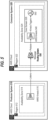
- FIG. 5 is a schematic illustrating an example of deployment of a message routing system according to the present disclosure.
- a producer system 510 and a consumer system 520 both systems being deployed on a third-party cloud environment, which in this example is an Amazon Web Services (AWS) Cloud.
- AWS Amazon Web Services
- the producer system 510 in Fig. 5 includes a first region 512, which corresponds to a physical location where AWS has one or more data centres.
- the first region 512 further includes a first availability zone 514 which corresponds to a physically isolated location within the first region 512.
- a first Amazon Kinesis 516 is hosted within the first availability zone 514 for streaming data and processing events.
- the consumer system 520 includes a second region 522, which may be the same region as the first region 512 or it may be a different region.
- the second region 522 further includes a second availability zone 524 which corresponds to a physically isolated location with the second region 522.
- the second availability zone 524 may be the same as the first availability zone 514 or it may be a different availability zone.
- a second Amazon Kinesis 540 is hosted within a core domain 526 of the first availability zone 524 along with an events listener module 550 (which may be an Amazon Lambda service).
- a message routing module 530 is deployed.
- the message routing system 530 in this example may be an embodiment of the message routing system 100 as described with reference to Fig.
- FIG. 5 only shows the first availability zone 514 and the second availability zone 524, it will be appreciated that depending on the resiliency requirements of the consumer system 520, additional availability zones may be provided so as to implement the deployment of the message routing system 530 in each availability zone.
- Fig. 6 is a schematic illustrating another example of deployment of a message routing system according to the present disclosure.
- a producer system AWS account 610 and a consumer system AWS account 620.
- the producer system AWS account 610 comprises a first virtual private cloud (VPC) 612 on which AWS Managed Kafka 614 is hosted.
- VPC virtual private cloud
- AWS secrets manager 616 at the producer system AWS account 610.
- the message routing system 630 is configured to communicate content messages from AWS Managed Kafka 614 hosted in the producer system AWS account 610 and route these content messages towards Amazon Kinesis 650 hosted in the consumer system AWS account 620.
- the message routing system 630 is also configured to communicate content messages from Amazon Kinesis 650 hosted in the PPE domain AWS account 620 and route these content messages towards AWS Managed Kafka 614 hosted in the producer system AWS account 610.
- the routing of content messages is represented by a double-headed arrow between an icon within AWS Managed Kafka 614 (designating a specific Kafka topic) and the message routing system 630 and an arrow between the message routing system 630 and Amazon Kinesis 650.
- Each content message to be routed has a corresponding routing configuration that is provided by the parameter store 670, and a message routing module (not shown in Fig. 6 ) of the message routing system 630 can route the respective content message according to the source and the target specified in the corresponding routing configuration provided by the parameter store 670.
- Content messages received at Amazon Kinesis 650 can trigger code execution at the events listener module 640 in response to the events represented by the content messages.
- the AWS secrets manager 616 can store a secret (e.g. credentials) associated with AWS Managed Kafka 614 and to provide said secret to the IAM role 660 at the consumer system AWS account 620.
- the IAM role 660 is configured to receive secrets from the AWS secrets manager 616 and to control access to the message routing system 630 on the basis of the received secrets.
- the AWS secrets manager 616 may support the use of SCRAM for authenticating users/clients.
- Fig. 7 is a schematic illustrating another example of deployment of a message routing system according to the present disclosure.
- the deployment arrangement of Fig. 7 is similar to that illustrated in Fig. 6 , with the main difference being that the arrangement of Fig. 7 involves the deployment of a message routing system between Amazon Kinesis at the consumer domain and Amazon Kinesis at the PPE domain, while Fig. 6 involves the deployment of a message routing system between AWS Managed Kafka and Amazon Kinesis.
- a producer system AWS account 710 and a consumer system AWS account 720 there is provided a producer system AWS account 710 and a consumer system AWS account 720.
- the producer system AWS account 710 comprises a first VPC 712 on which a first Amazon Kinesis 714 is hosted.
- the consumer system AWS account 720 comprises a second VPC 722 on which a message routing system 730 and an events listener module 740 are hosted.
- a second Amazon Kinesis 750, a parameter store 760, and an IAM role 770 there is provided.
- the message routing system 730 in this example may be an embodiment of the message routing system 100 as described with reference to Fig. 1 , and is thus capable of performing all the functionalities of the message routing system 100.
- the message routing system 730 is configured to communicate content messages from the first Amazon Kinesis 714 hosted in the producer system AWS account 710 and route these content messages towards the second Amazon Kinesis 750 hosted in the consumer system AWS account 720.
- the message routing system 730 is also configured to communicate content messages from the second Amazon Kinesis 750 hosted in the consumer system AWS account 720 and route these content messages towards the first Amazon Kinesis 714 hosted in the producer system AWS account 710.
- the routing of content messages is represented by a double-headed arrow between the first Amazon Kinesis 714 and the message routing system 730 and an arrow between the message routing system 730 and the second Amazon Kinesis 750.
- the IAM role 770 at the consumer system AWS account 720 is configured to control access to the message routing system 730 by granting permission based on a defined set of permissions policies.
- Figs. 8 to 10 are schematics illustrating various aspects of a cloud computing environment system that may comprise the message routing system as described herein, and computer hardware that is configured to implement the cloud computing environment system, the message routing system as described herein, of the methods described herein.
- Fig. 8 is a schematic illustrating an exemplary system for implementing a method of the invention.
- cloud environment 800 is communicatively coupled via communication network 810 to secure provider 830, one or more users 840, and one or more external providers 850.
- communication network 810 may be implemented or facilitated using one or more local or wide-area communications networks, such as the Internet, WiFi networks, WiMax networks, and the like. Generally, the Internet is used.
- communication network 810 may utilise encryption (e.g., Secure Sockets Layer) to secure data being transferred over the communication network 810 to the cloud environment 800.
- encryption e.g., Secure Sockets Layer
- Cloud environment 800 is owned and maintained by a third party, i.e. a party that is not the secure provider 830, not one of the one or more users 840, and not one of the external providers 850. Accordingly, cloud environment 800 may be referred to as "a third-party cloud environment". Examples of third-party cloud environments include Amazon Web Services (AWS), Google Cloud Platform, and IMB Cloud. By connecting to a multitude of users 840, cloud environment 800 is able to benefit from economies of scale, thereby making processing and storing large quantities of data in cloud environment 800 efficient.
- AWS Amazon Web Services
- Google Cloud Platform Google Cloud Platform
- IMB Cloud IMB Cloud
- cloud environment 800 hosts computer executable code 1024 (not shown) which is executed in the cloud environment 800 in response to a request from user 840.
- Execution of the computer executable code 1024 causes data to be processed, and the output data produced by executing the computer executable code 1024 is available for user 840 to access.
- the computer resources required for data processing are outsourced from the user to the cloud environment 800.
- user 840 can send the request from anywhere, as long as they have connection to cloud environment 800 via communication network 810. Since the communication network 810 is typically the Internet, which is ubiquitous, the accessibility of cloud environment 800 to user 840 is extremely high.
- User 840 of the cloud environment 800 may additionally or alternatively develop computer executable code 1024 for execution in the cloud environment 800.
- User 840 can access computer executable code 1024 in cloud environment 800 through a web browser or any other appropriate client application residing on a client computer.
- computer executable code 1024 may process data or use data. This data is made available to the cloud environment 800 by including particular services in the computer executable code 1024 such as access to REST (Representational State Transfer) APIs (Application Programming Interface) or similar communication protocols. REST APIs work by making HTTP requests to GET, PUT, POST and DELETE data. Thus, when the computer executable code 1024 makes a request for data, it may do so by making a HTTP GET request to the data source. Such services (and therefore data) may be provided either internally within the cloud environment 800, or externally by one or more external providers 850.
- REST Real State Transfer
- APIs Application Programming Interface
- Such services and therefore data
- Such services may be provided either internally within the cloud environment 800, or externally by one or more external providers 850.
- Fig. 9 shows an exemplary third-party cloud environment 800 for implementing a method of the invention.
- cloud environment 800 comprises cloud environment hardware 902 that can be invoked to instantiate data processing, data storage, or other computer resources using cloud computing hardware 902 for a limited or defined duration.
- Cloud environment hardware 902 may comprise one or more servers 900 1 to 900 n , and a storage array network 910, as well as any other suitable hardware.
- Cloud environment hardware 902 may be configured to provide a virtualisation environment 920 that supports the execution of a plurality of virtual machines 1010 (not shown) across the one or more servers 900 1 to 900 n .
- the plurality of virtual machines 1010 provide various services and functions for cloud environment 800.
- Virtualisation environment 920 of Fig. 9 may include orchestration component 922 that monitors the cloud environment hardware 902 resource consumption levels and the requirements of cloud environment 800 (e.g., by monitoring communications routed through addressing and discovery layer 924), and provides additional cloud environment hardware 902 to cloud environment 800 as needed. For example, if cloud environment 800 requires additional virtual machines 1010 to host new computer executable code 1024, orchestration component 922 can initiate and manage the instantiation of the virtual machines 1010 on the one or more servers 900 1 to 900 n to support such needs.
- virtualisation environment 920 may be implemented by running Amazon Elastic Compute Cloud (Amazon EC2) on servers 900 1 to 900 n . It should be recognised that any other virtualization technologies may alternatively be utilised.
- Amazon Elastic Compute Cloud Amazon Elastic Compute Cloud
- Cloud environment 800 supports an execution environment 932 that comprises a plurality of virtual machines 1010 (or containers 1020, as is discussed in relation to Fig. 10 ) instantiated to host deployed computer executable code 1024.
- deployment by user 840 or by secure provider 830 of computer executable code 1024 to the cloud environment 800 results in the hosting of computer executable code 1024 in virtual machine 1010 1 and/or container 1020 1 , of execution environment 932.
- Computer executable code 1024 can access internal services provided by cloud environment 800 as well as external services from one or more external providers 850 and/or from secure provider 830. Services may include, for example, accessing a REST API, a custom database, a relational database service (e.g., MySQL, etc.), monitoring service, background task scheduler, logging service, messaging service, memory object caching service and the like.
- a service provisioner 930 serves as a communications intermediary between these available services (e.g., internal services and external services) and other components of cloud environment 800 (e.g., cloud controller 938, router 936, containers 1020) and assists with provisioning available services to computer executable code 1024 during the deployment process.
- addressing and discovery layer 924 provides a common interface through which components of cloud computing environment 800, such as service provisioner 930, cloud controller 938, router 936 and containers 920 in the execution environment 932 can communicate.
- service provisioner 1030 may communicate through addressing and discovery layer 924 to broadcast the availability of services and to propagate service provisioning data for such services during deployment of computer executable code 1024 in cloud environment 800.
- Cloud controller 938 is configured to orchestrate the deployment process for computer executable code 924 that is submitted to cloud environment 800 by the user 840 or the secure provider 830.
- cloud controller 938 receives computer executable code 1024 submitted to cloud computing environment 800 from user 840 or secure provider 830 and, as further detailed below, interacts with other components of cloud environment 800 to call services required by the computer executable code 1024 and package the computer executable code 1024 for transmission to available containers 1020.
- An example cloud controller 938 service is Amazon Elastic Container service (ECS).
- Fig. 9 is merely exemplary and that alternative cloud environment architectures may be implemented consistent with the teachings herein.
- Fig. 9 implements cloud computing environment 800 on cloud environment hardware 902
- cloud environment 800 may be implemented by a third-party in an alternative manner and on top of any type of hardware.
- Fig. 10 is a schematic of an exemplary server 900 for implementing a method of the invention.
- Fig. 10 depicts server 900 comprising server hardware 1002 and virtual machine execution environment 1032 having containers 1020 with computer executable code 1024.
- the server hardware 1002 may include local storage 1004, such as a hard drive, network adapter 1005, system memory 1006, processor 1007 and other I/O devices such as, for example, a mouse and keyboard (not shown).
- Hypervisor 1012 is responsible for transforming I/O requests from guest operating system 1027 to virtual machines 1010, into corresponding requests to server hardware 1002.
- guest operating system 1027 of container 1020 supports the execution of deployment agent 1025, which is a process or daemon that communicates (e.g., via addressing and discovery layer 924) with cloud controller 938 to receive and unpack computer executable code 1024 and its deployment package.
- deployment agent 1025 also communicates with router 936 to provide network routing information for computer executable code 1024 that have been deployed in container 1020.
- Guest operating system 1027 further supports the execution of runtime environment 1026 within which computer executable code 1024 is executed.
- a computer-readable storage medium carrying the computer program may form aspects of the invention.
- the computer program may have one or more program instructions, or program code, which, when executed by a processor, carries out an embodiment of the invention.
- program or "software” as used herein, may be a sequence of instructions designed for execution on a computer system, and may include a subroutine, a function, a procedure, a module, an object method, an object implementation, an executable application, an applet, a servlet, source code, object code, a shared library, a dynamic linked library, and/or other sequences of instructions designed for execution for execution on a computer system.
- the storage medium may be magnetic disc, an optical disc, or a memory (e.g. a ROM, a RAM, EEPROM, EPROM, flash memory or a portable/removable memory device), etc.
- the transmission medium may be communications signal, a data broadcast, a communications link between two or more computers, etc.
Landscapes
- Engineering & Computer Science (AREA)
- Computer Networks & Wireless Communication (AREA)
- Signal Processing (AREA)
- Data Exchanges In Wide-Area Networks (AREA)
Claims (15)
- Nachrichtenroutingsystem (100), das Folgendes umfasst:ein Nachrichtenroutingmodul (110);ein Routingkonfigurationsmodul (120), das dazu konfiguriert ist, eine Routingkonfiguration für jede von einer oder mehreren Inhaltsnachrichten bereitzustellen, wobei jede Routingkonfiguration eine Quelle der jeweiligen Inhaltsnachricht und ein oder mehrere Ziele für die jeweilige Inhaltsnachricht umfasst und wobei sowohl die Quelle als auch das eine oder die mehreren Ziele durch einen Kanal und eine Adresse gekennzeichnet sind;ein erstes Bindermodul (130), das dazu konfiguriert ist, eine erste Datenstreaminganwendung (DSA1) unter Verwendung eines oder mehrerer Kanäle mit dem Nachrichtenroutingmodul zu verbinden, wobei das erste Bindermodul dazu konfiguriert ist, einer Inhaltsnachricht zu ermöglichen, zu und/oder von der ersten Datenstreaminganwendung geroutet zu werden;ein zweites Bindermodul (140), das dazu konfiguriert ist, eine zweite Datenstreaminganwendung (DSA2) unter Verwendung eines oder mehrerer Kanäle mit dem Nachrichtenroutingmodul zu verbinden, wobei das zweite Bindermodul dazu konfiguriert ist, einer Inhaltsnachricht zu ermöglichen, zu und/oder von der zweiten Datenstreaminganwendung geroutet zu werden,wobei die erste Datenstreaminganwendung mit einem ersten cloudbasierten Konto assoziiert ist und die zweite Datenstreaminganwendung mit einem zweiten cloudbasierten Konto assoziiert ist;wobei das Nachrichtenroutingmodul dazu konfiguriert ist:eine Inhaltsnachricht von einer Datenstreaminganwendung und einer entsprechenden Routingkonfiguration für die Inhaltsnachricht von dem Routingkonfigurationsmodul zu empfangen; unddie Inhaltsnachricht gemäß der entsprechenden Routingkonfiguration unter Verwendung einer Strombrückenschnittstelle (150) zu routen.
- Nachrichtenroutingsystem (100) nach Anspruch 1, wobei eine Adresse, die eine Quelle oder ein Ziel kennzeichnet, einen Inhaltsnachrichtenstrom an einer entsprechenden Datenstreaminganwendung bezeichnet.
- Nachrichtenroutingsystem (100) nach Anspruch 1 oder Anspruch 2, wobei das Nachrichtenroutingmodul (110) ferner dazu konfiguriert ist:zu bestimmen, dass die Inhaltsnachricht geliefert wurde; undnach dem Bestimmen, dass die Inhaltsnachricht geliefert wurde, eine Bestätigung an die jeweilige Datenstreaminganwendung zu senden, die in der entsprechenden Routingkonfiguration als Quelle angegeben ist, um einen Datenoffset auszulösen, der in Bezug auf die gelieferte Inhaltsnachricht an der jeweiligen Datenstreaminganwendung festgeschrieben wird.
- Nachrichtenroutingsystem (100) nach einem der vorhergehenden Ansprüche,wobei die erste Datenstreaminganwendung (DSA1) aus einer Liste ausgewählt ist, die Folgendes beinhaltet: Amazon Managed Streaming für Amazon Web Services, AWS, Managed Kafka, Amazon Kinesis, Rabbit MQ, Amazon Simple Notification Service, Amazon Simple Queue Service und Apache RocketMQ, undwobei die zweite Datenstreaminganwendung (DSA2) eine andere Datenstreaminganwendung ist, die aus der Liste ausgewählt ist.
- Nachrichtenroutingsystem (100) nach einem der vorhergehenden Ansprüche, wobei das Nachrichtenroutingsystem auf einer Verbraucherdomäne eingesetzt wird.
- Nachrichtenroutingsystem (100) nach einem der vorhergehenden Ansprüche, das ferner ein Geheimhaltungsverwaltungsmodul (160) umfasst, das dazu konfiguriert ist, ein oder mehrere Geheimnisse, die mit der ersten und/oder der zweiten Datenstreaminganwendung assoziiert sind, basierend auf einer vorbestimmten Konfiguration zu rotieren.
- Nachrichtenroutingsystem (100) nach Anspruch 6, wobei das erste (130) und/oder das zweite (140) Bindermodul einen Gesundheitsendpunkt umfasst, der dazu konfiguriert ist:einen oder mehrere Gesundheitsstatusparameter der jeweiligen Datenstreaminganwendung zu erfassen, wobei der eine oder mehrere Gesundheitsstatusparameter einen Geheimnisrotationsparameter umfassen, der angibt, ob ein Geheimnis, das mit der jeweiligen Datenstreaminganwendung assoziiert ist, rotiert wird; unddie jeweilige Datenstreaminganwendung neu zu starten, wenn mindestens einer von einem oder mehreren Gesundheitsstatusparametern ein vorbestimmtes Kriterium nicht erfüllt.
- Nachrichtenroutingsystem (100) nach einem der vorhergehenden Ansprüche, wobei das Nachrichtenroutingmodul (110) dazu konfiguriert ist, die Inhaltsnachricht durch Abrufen der Inhaltsnachricht von der jeweiligen Datenstreaminganwendung zu empfangen.
- Nachrichtenroutingsystem (100) nach einem der vorhergehenden Ansprüche, wobei die Routingkonfiguration für eine Inhaltsnachricht eine Quelle der jeweiligen Inhaltsnachricht und mehrere Ziele für die jeweilige Inhaltsnachricht umfasst.
- Nachrichtenroutingsystem (100) nach einem der vorhergehenden Ansprüche, das ferner ein Metriküberwachungsmodul (170) umfasst, das dazu konfiguriert ist, eine Anzahl von Inhaltsnachrichten, die von der ersten Datenstreaminganwendung (DSA1) oder der zweiten Datenstreaminganwendung (DSA2) empfangen wurden, die erfolgreich geliefert wurden, und/oder eine Anzahl von Inhaltsnachrichten, die von der ersten Datenstreaminganwendung oder der zweiten Datenstreaminganwendung empfangen wurden, die nicht geliefert wurden, zu bestimmen.
- Computerimplementiertes Verfahren (200) zum Betreiben eines Nachrichtenroutingsystems, wobei das Nachrichtenroutingsystem ein Nachrichtenroutingmodul, ein Routingkonfigurationsmodul, ein erstes Bindermodul, das dazu konfiguriert ist, eine erste Datenstreaminganwendung (DSA1) mit dem Nachrichtenroutingmodul unter Verwendung eines oder mehrerer Kanäle zu verbinden, wobei das erste Bindermodul dazu konfiguriert ist, zu ermöglichen, dass eine Inhaltsnachricht zu und/oder von der ersten Datenstreaminganwendung geroutet wird, und ein zweites Bindermodul, das dazu konfiguriert ist, eine zweite Datenstreaminganwendung (DSA2) unter Verwendung eines oder mehrerer Kanäle mit dem Nachrichtenroutingmodul zu verbinden, umfasst, wobei das zweite Bindermodul dazu konfiguriert ist, zu ermöglichen, dass eine Inhaltsnachricht zu und/oder von der ersten Datenstreaminganwendung geroutet wird, wobei das Verfahren Folgendes umfasst:Bereitstellen (210), durch das Routingkonfigurationsmodul, einer Routingkonfiguration für jede von einer oder mehreren Inhaltsnachrichten, wobei jede Routingkonfiguration eine Quelle der jeweiligen Inhaltsnachricht und ein oder mehrere Ziele für die jeweilige Inhaltsnachricht umfasst und wobei sowohl die Quelle als auch das eine oder die mehreren Ziele durch einen Kanal und eine Adresse gekennzeichnet sind;Empfangen (220), an dem Nachrichtenroutingmodul, einer Inhaltsnachricht von einer ersten Datenstreaminganwendung oder einer zweiten Datenstreaminganwendung und einer entsprechenden Routingkonfiguration für die Inhaltsnachricht von dem Routingkonfigurationsmodul; undRouten (230), durch das Nachrichtenroutingmodul, der Inhaltsnachricht gemäß der entsprechenden Routingkonfiguration unter Verwendung einer Strombrückenschnittstelle,wobei die erste Datenstreaminganwendung mit einem ersten cloudbasierten Konto assoziiert ist und die zweite Datenstreaminganwendung mit einem zweiten cloudbasierten Konto assoziiert ist.
- Computerimplementiertes Verfahren (200) nach Anspruch 11, das ferner Folgendes umfasst:Bestimmen, durch das Nachrichtenroutingmodul, dass die Inhaltsnachricht geliefert wurde; undnach dem Bestimmen, dass die Inhaltsnachricht geliefert wurde, Senden, durch das Nachrichtenroutingmodul, einer Bestätigung an die jeweilige Datenstreaminganwendung, die in der entsprechenden Routingkonfiguration als Quelle angegeben ist, um einen Datenoffset auszulösen, der in Bezug auf die gelieferte Inhaltsnachricht an der jeweiligen Datenstreaminganwendung festgeschrieben wird.
- Computerimplementiertes Verfahren (200) nach Anspruch 11 oder Anspruch 12, wobei das erste und/oder das zweite Bindermodul einen Gesundheitsendpunkt umfasst, wobei das Verfahren ferner Folgendes umfasst:Erfassen, durch einen Gesundheitsendpunkt eines Bindermoduls, eines oder mehrerer Gesundheitsstatusparameter der jeweiligen Datenstreaminganwendung, wobei der eine oder die mehreren Gesundheitsstatusparameter einen Geheimnisrotationsparameter umfassen, der angibt, ob ein Geheimnis, das mit der jeweiligen Datenstreaminganwendung assoziiert ist, rotiert wird; underneutes Starten der jeweiligen Datenstreaminganwendung, wenn mindestens einer von einem oder mehreren Gesundheitsstatusparametern ein vorbestimmtes Kriterium nicht erfüllt.
- Cloud-Computing-Umgebungssystem, das das Nachrichtenroutingsystem nach einem der Ansprüche 1 bis 10 umfasst.
- Computerhardware, die dazu konfiguriert ist, das Nachrichtenroutingsystem nach einem der Ansprüche 1 bis 10, das Verfahren nach einem der Ansprüche 11 bis 13 oder das Cloud-Computing-Umgebungssystem nach Anspruch 14 zu implementieren.
Priority Applications (2)
| Application Number | Priority Date | Filing Date | Title |
|---|---|---|---|
| EP23157649.7A EP4418625B1 (de) | 2023-02-20 | 2023-02-20 | Nachrichtenleitweglenkungssystem |
| US18/582,538 US12388779B2 (en) | 2023-02-20 | 2024-02-20 | Message routing system |
Applications Claiming Priority (1)
| Application Number | Priority Date | Filing Date | Title |
|---|---|---|---|
| EP23157649.7A EP4418625B1 (de) | 2023-02-20 | 2023-02-20 | Nachrichtenleitweglenkungssystem |
Publications (3)
| Publication Number | Publication Date |
|---|---|
| EP4418625A1 EP4418625A1 (de) | 2024-08-21 |
| EP4418625B1 true EP4418625B1 (de) | 2025-03-26 |
| EP4418625C0 EP4418625C0 (de) | 2025-03-26 |
Family
ID=85321074
Family Applications (1)
| Application Number | Title | Priority Date | Filing Date |
|---|---|---|---|
| EP23157649.7A Active EP4418625B1 (de) | 2023-02-20 | 2023-02-20 | Nachrichtenleitweglenkungssystem |
Country Status (2)
| Country | Link |
|---|---|
| US (1) | US12388779B2 (de) |
| EP (1) | EP4418625B1 (de) |
Families Citing this family (1)
| Publication number | Priority date | Publication date | Assignee | Title |
|---|---|---|---|---|
| CN119402405B (zh) * | 2024-10-29 | 2025-10-10 | 中国建设银行股份有限公司 | 一种灵活配置报文路由调度的方法、装置及设备 |
Family Cites Families (8)
| Publication number | Priority date | Publication date | Assignee | Title |
|---|---|---|---|---|
| GB2354913B (en) * | 1999-09-28 | 2003-10-08 | Ibm | Publish/subscribe data processing with publication points for customised message processing |
| CA2361861A1 (en) * | 2001-11-13 | 2003-05-13 | Ibm Canada Limited-Ibm Canada Limitee | Wireless messaging services using publish/subscribe systems |
| IL218185B (en) | 2012-02-19 | 2018-12-31 | Safe T Data A R Ltd | Reverse access system for securing front-end applications |
| US10666712B1 (en) * | 2016-06-10 | 2020-05-26 | Amazon Technologies, Inc. | Publish-subscribe messaging with distributed processing |
| US10764375B2 (en) | 2016-10-13 | 2020-09-01 | Sierraware, Llc | Method for cloud based mobile application virtualization |
| US10645181B2 (en) * | 2016-12-12 | 2020-05-05 | Sap Se | Meta broker for publish-subscribe-based messaging |
| US11201937B2 (en) * | 2018-11-22 | 2021-12-14 | Jeffrey Alan Carley | Message broker customization with user administered policy functions |
| US10986150B2 (en) * | 2019-03-01 | 2021-04-20 | Netskope, Inc. | Load balancing in a dynamic scalable services mesh |
-
2023
- 2023-02-20 EP EP23157649.7A patent/EP4418625B1/de active Active
-
2024
- 2024-02-20 US US18/582,538 patent/US12388779B2/en active Active
Also Published As
| Publication number | Publication date |
|---|---|
| US20240283767A1 (en) | 2024-08-22 |
| US12388779B2 (en) | 2025-08-12 |
| EP4418625A1 (de) | 2024-08-21 |
| EP4418625C0 (de) | 2025-03-26 |
Similar Documents
| Publication | Publication Date | Title |
|---|---|---|
| US11394714B2 (en) | Controlling user access to command execution | |
| US9489227B2 (en) | Apparatus and method for virtual desktop service | |
| CN111164571B (zh) | 云系统中的基于安全处理的控制平面功能虚拟化 | |
| US20210099491A1 (en) | Policy engine for cloud platform | |
| US10044756B2 (en) | Enabling an on-premises resource to be exposed to a public cloud application securely and seamlessly | |
| US10019273B2 (en) | Virtual environment manager | |
| US20120066487A1 (en) | System and method for providing load balancer visibility in an intelligent workload management system | |
| US20200287885A1 (en) | Protecting sensitive information in single sign-on (SSO) to the cloud | |
| US9521053B1 (en) | Providing diagnostic metrics for virtual connections over physical connections into a provider network | |
| US9753786B2 (en) | Client server communication system | |
| US11520609B2 (en) | Template-based software discovery and management in virtual desktop infrastructure (VDI) environments | |
| US10785056B1 (en) | Sharing a subnet of a logically isolated network between client accounts of a provider network | |
| US20200249975A1 (en) | Virtual machine management | |
| US12413579B2 (en) | Securing connections between a networking and security controller and distributed agents in a container-based cluster | |
| US9760412B2 (en) | Client server communication system | |
| US11190577B2 (en) | Single data transmission using a data management server | |
| US12388779B2 (en) | Message routing system | |
| US9652279B1 (en) | Remotely interacting with a virtualized machine instance | |
| US20210105194A1 (en) | Cloud computing environment with split connectivity and application interfaces that enable support of separate cloud services | |
| US20230273825A1 (en) | Global service catalog for provisioning services on a multi-cluster service mesh of a multi-cluster computing environment | |
| Benedetti et al. | Open-source serverless for edge computing: a tutorial | |
| US20170048256A1 (en) | Transparent asynchronous network flow information exchange | |
| US10599483B1 (en) | Decentralized task execution bypassing an execution service | |
| CN119561986A (zh) | 一种资源调用方法、系统及相关设备 | |
| KR20140144122A (ko) | 클라우드 시스템의 클라이언트 |
Legal Events
| Date | Code | Title | Description |
|---|---|---|---|
| PUAI | Public reference made under article 153(3) epc to a published international application that has entered the european phase |
Free format text: ORIGINAL CODE: 0009012 |
|
| STAA | Information on the status of an ep patent application or granted ep patent |
Free format text: STATUS: THE APPLICATION HAS BEEN PUBLISHED |
|
| AK | Designated contracting states |
Kind code of ref document: A1 Designated state(s): AL AT BE BG CH CY CZ DE DK EE ES FI FR GB GR HR HU IE IS IT LI LT LU LV MC ME MK MT NL NO PL PT RO RS SE SI SK SM TR |
|
| STAA | Information on the status of an ep patent application or granted ep patent |
Free format text: STATUS: REQUEST FOR EXAMINATION WAS MADE |
|
| 17P | Request for examination filed |
Effective date: 20240912 |
|
| RBV | Designated contracting states (corrected) |
Designated state(s): AL AT BE BG CH CY CZ DE DK EE ES FI FR GB GR HR HU IE IS IT LI LT LU LV MC ME MK MT NL NO PL PT RO RS SE SI SK SM TR |
|
| GRAP | Despatch of communication of intention to grant a patent |
Free format text: ORIGINAL CODE: EPIDOSNIGR1 |
|
| STAA | Information on the status of an ep patent application or granted ep patent |
Free format text: STATUS: GRANT OF PATENT IS INTENDED |
|
| RIC1 | Information provided on ipc code assigned before grant |
Ipc: H04L 45/00 20220101ALI20240930BHEP Ipc: H04L 45/302 20220101AFI20240930BHEP |
|
| INTG | Intention to grant announced |
Effective date: 20241022 |
|
| GRAS | Grant fee paid |
Free format text: ORIGINAL CODE: EPIDOSNIGR3 |
|
| GRAA | (expected) grant |
Free format text: ORIGINAL CODE: 0009210 |
|
| STAA | Information on the status of an ep patent application or granted ep patent |
Free format text: STATUS: THE PATENT HAS BEEN GRANTED |
|
| AK | Designated contracting states |
Kind code of ref document: B1 Designated state(s): AL AT BE BG CH CY CZ DE DK EE ES FI FR GB GR HR HU IE IS IT LI LT LU LV MC ME MK MT NL NO PL PT RO RS SE SI SK SM TR |
|
| REG | Reference to a national code |
Ref country code: GB Ref legal event code: FG4D |
|
| REG | Reference to a national code |
Ref country code: CH Ref legal event code: EP |
|
| REG | Reference to a national code |
Ref country code: DE Ref legal event code: R096 Ref document number: 602023002532 Country of ref document: DE |
|
| REG | Reference to a national code |
Ref country code: IE Ref legal event code: FG4D |
|
| U01 | Request for unitary effect filed |
Effective date: 20250416 |
|
| U07 | Unitary effect registered |
Designated state(s): AT BE BG DE DK EE FI FR IT LT LU LV MT NL PT RO SE SI Effective date: 20250424 |
|
| PG25 | Lapsed in a contracting state [announced via postgrant information from national office to epo] |
Ref country code: RS Free format text: LAPSE BECAUSE OF FAILURE TO SUBMIT A TRANSLATION OF THE DESCRIPTION OR TO PAY THE FEE WITHIN THE PRESCRIBED TIME-LIMIT Effective date: 20250626 |
|
| PG25 | Lapsed in a contracting state [announced via postgrant information from national office to epo] |
Ref country code: NO Free format text: LAPSE BECAUSE OF FAILURE TO SUBMIT A TRANSLATION OF THE DESCRIPTION OR TO PAY THE FEE WITHIN THE PRESCRIBED TIME-LIMIT Effective date: 20250626 |
|
| PG25 | Lapsed in a contracting state [announced via postgrant information from national office to epo] |
Ref country code: HR Free format text: LAPSE BECAUSE OF FAILURE TO SUBMIT A TRANSLATION OF THE DESCRIPTION OR TO PAY THE FEE WITHIN THE PRESCRIBED TIME-LIMIT Effective date: 20250326 |
|
| PG25 | Lapsed in a contracting state [announced via postgrant information from national office to epo] |
Ref country code: GR Free format text: LAPSE BECAUSE OF FAILURE TO SUBMIT A TRANSLATION OF THE DESCRIPTION OR TO PAY THE FEE WITHIN THE PRESCRIBED TIME-LIMIT Effective date: 20250627 |
|
| PG25 | Lapsed in a contracting state [announced via postgrant information from national office to epo] |
Ref country code: SM Free format text: LAPSE BECAUSE OF FAILURE TO SUBMIT A TRANSLATION OF THE DESCRIPTION OR TO PAY THE FEE WITHIN THE PRESCRIBED TIME-LIMIT Effective date: 20250326 |
|
| PG25 | Lapsed in a contracting state [announced via postgrant information from national office to epo] |
Ref country code: ES Free format text: LAPSE BECAUSE OF FAILURE TO SUBMIT A TRANSLATION OF THE DESCRIPTION OR TO PAY THE FEE WITHIN THE PRESCRIBED TIME-LIMIT Effective date: 20250326 |
|
| PG25 | Lapsed in a contracting state [announced via postgrant information from national office to epo] |
Ref country code: PL Free format text: LAPSE BECAUSE OF FAILURE TO SUBMIT A TRANSLATION OF THE DESCRIPTION OR TO PAY THE FEE WITHIN THE PRESCRIBED TIME-LIMIT Effective date: 20250326 |
|
| PG25 | Lapsed in a contracting state [announced via postgrant information from national office to epo] |
Ref country code: SK Free format text: LAPSE BECAUSE OF FAILURE TO SUBMIT A TRANSLATION OF THE DESCRIPTION OR TO PAY THE FEE WITHIN THE PRESCRIBED TIME-LIMIT Effective date: 20250326 |
|
| PG25 | Lapsed in a contracting state [announced via postgrant information from national office to epo] |
Ref country code: IS Free format text: LAPSE BECAUSE OF FAILURE TO SUBMIT A TRANSLATION OF THE DESCRIPTION OR TO PAY THE FEE WITHIN THE PRESCRIBED TIME-LIMIT Effective date: 20250726 |
|
| PG25 | Lapsed in a contracting state [announced via postgrant information from national office to epo] |
Ref country code: CZ Free format text: LAPSE BECAUSE OF FAILURE TO SUBMIT A TRANSLATION OF THE DESCRIPTION OR TO PAY THE FEE WITHIN THE PRESCRIBED TIME-LIMIT Effective date: 20250326 |
|
| PGFP | Annual fee paid to national office [announced via postgrant information from national office to epo] |
Ref country code: IE Payment date: 20251223 Year of fee payment: 4 |
|
| PLBE | No opposition filed within time limit |
Free format text: ORIGINAL CODE: 0009261 |
|
| STAA | Information on the status of an ep patent application or granted ep patent |
Free format text: STATUS: NO OPPOSITION FILED WITHIN TIME LIMIT |
|
| REG | Reference to a national code |
Ref country code: CH Ref legal event code: L10 Free format text: ST27 STATUS EVENT CODE: U-0-0-L10-L00 (AS PROVIDED BY THE NATIONAL OFFICE) Effective date: 20260211 |
|
| U20 | Renewal fee for the european patent with unitary effect paid |
Year of fee payment: 4 Effective date: 20260106 |
|
| 26N | No opposition filed |
Effective date: 20260105 |