EP4418529A1 - Controller for a switched reluctance machine - Google Patents
Controller for a switched reluctance machine Download PDFInfo
- Publication number
- EP4418529A1 EP4418529A1 EP23156917.9A EP23156917A EP4418529A1 EP 4418529 A1 EP4418529 A1 EP 4418529A1 EP 23156917 A EP23156917 A EP 23156917A EP 4418529 A1 EP4418529 A1 EP 4418529A1
- Authority
- EP
- European Patent Office
- Prior art keywords
- controller
- phase
- phases
- machine
- energised
- Prior art date
- Legal status (The legal status is an assumption and is not a legal conclusion. Google has not performed a legal analysis and makes no representation as to the accuracy of the status listed.)
- Pending
Links
Images


Classifications
-
- H—ELECTRICITY
- H02—GENERATION; CONVERSION OR DISTRIBUTION OF ELECTRIC POWER
- H02P—CONTROL OR REGULATION OF ELECTRIC MOTORS, ELECTRIC GENERATORS OR DYNAMO-ELECTRIC CONVERTERS; CONTROLLING TRANSFORMERS, REACTORS OR CHOKE COILS
- H02P25/00—Arrangements or methods for the control of AC motors characterised by the kind of AC motor or by structural details
- H02P25/02—Arrangements or methods for the control of AC motors characterised by the kind of AC motor or by structural details characterised by the kind of motor
- H02P25/08—Reluctance motors
- H02P25/086—Commutation
- H02P25/089—Sensorless control
-
- H—ELECTRICITY
- H02—GENERATION; CONVERSION OR DISTRIBUTION OF ELECTRIC POWER
- H02P—CONTROL OR REGULATION OF ELECTRIC MOTORS, ELECTRIC GENERATORS OR DYNAMO-ELECTRIC CONVERTERS; CONTROLLING TRANSFORMERS, REACTORS OR CHOKE COILS
- H02P25/00—Arrangements or methods for the control of AC motors characterised by the kind of AC motor or by structural details
- H02P25/02—Arrangements or methods for the control of AC motors characterised by the kind of AC motor or by structural details characterised by the kind of motor
- H02P25/08—Reluctance motors
-
- H—ELECTRICITY
- H02—GENERATION; CONVERSION OR DISTRIBUTION OF ELECTRIC POWER
- H02P—CONTROL OR REGULATION OF ELECTRIC MOTORS, ELECTRIC GENERATORS OR DYNAMO-ELECTRIC CONVERTERS; CONTROLLING TRANSFORMERS, REACTORS OR CHOKE COILS
- H02P2101/00—Special adaptation of control arrangements for generators
- H02P2101/30—Special adaptation of control arrangements for generators for aircraft
Definitions
- This application relates to a controller for a switched reluctance machine.
- Switched reluctance machines include a plurality of phases, a stator and a rotor, and may operate as a motor or a generator. In both operational modes, it is critical to know the angle of the rotor for control purposes, which may be determined by an electro-mechanical sensor. In some environments, for example aerospace applications, the machine may operate in extreme temperatures and be subject to vibration sufficient to cause the electro-mechanical sensor to fail. As a result, there is a need for determining the rotor angle without using an electro-mechanical sensor.
- a controller for a switched reluctance machine comprising two concurrently energised phases and two concurrently non-energised phases, the controller configured to in an injection stage, inject a signal into the two non-energised phases; in a measurement stage, determine the current in each of the two non-energised phases; and in a calculation stage, apply an algorithm to the determined currents to determine a rotor angle.
- the determination of the rotor angle according to the present invention is more reliable.
- the overall determination of rotor angle is less susceptible to error as any noise from one phase, for example due to Electro Magnetic Interference (EMI), can be compensated for by the other phase which may not be subject to the EMI.
- EMI Electro Magnetic Interference
- the switched reluctance machine comprises a rotor having a rotation cycle, and is configured such that at any point during the rotation cycle two phases of the machine are concurrently non-energised.
- the signal in the injection stage, is injected into each of the two non-energised phases such that two phases of the machine are receiving the injection signal at any point during the rotation cycle.
- the algorithm comprises signal processing the determined current of each phase to provide processed data for each phase; converting the processed data into an estimated rotor angle for each phase; and averaging the estimated angle from each phase to determine the rotor angle.
- the signal processing comprises applying a first low pass filter to the determined current to provide a filtered current; calculating an absolute value of the filtered current to provide an absolute current; and applying a second low pass filter to the absolute current to provide the processed data.
- the converting comprises using a look-up table to convert the processed data into an estimated rotor angle.
- the algorithm further comprises providing the determined rotor angle to a closed loop PI tracker.
- a PI tracker is an effective way of reducing the error in the rotor angle, making the tracking smoother, and filtering out sampling errors.
- the signal has a duty cycle of less than 50%. In some examples, the signal has a frequency of 30kHz. Using a frequency that is considerably higher than the normal operating frequency of the machine ensures minimal torque ripple and low levels of acoustic noise.
- controller is further configured to, in a power management stage, configure the flow of electrical power to or from the machine.
- controller is further configured to, in the calculation stage, provide the power management stage with the determined rotor angle; and in the power management stage, control the flow of electrical power to or from the machine based on the rotor angle.
- the controller is configured to, in the power management stage, control the flow of electrical power by controlling a timing of the electrical power supplied to each phase, or a rectification of the electrical power received by each phase.
- the switched reluctance machine comprises four phases; wherein in the power management stage, the controller is configured to control the flow of electrical power such that an initial motoring period of a first phase occurs concurrently with: a final generation period of a second phase, an initial generation period of a third phase, and a final motoring period of a fourth phase.
- the controller is configured to control the machine as a motor; wherein in the power management stage, the controller is configured to control the flow of electrical power to energise each phase during a motoring period to produce a motoring torque, and to energise the phases such that two phases are concurrently non-energised; and wherein in the injection stage the controller is configured to inject each phase during an initial generation period and a final generation period.
- a rotor of the machine is configured to energise each phase during a generation period to generate electrical power, and the machine is configured such that two phases are concurrently non-energised; and the controller is configured to control the machine as a generator; and in the injection stage, the controller is configured to inject each phase during an initial motoring period and a final motoring period.
- a switched reluctance machine comprising a rotor comprising a plurality of magnetic elements; a stator comprising two concurrently non-energised phases; and the controller of the first aspect configured to control the machine as a motor or as a generator.
- an aircraft comprising the switched reluctance machine of the second aspect.
- the controller when the controller is configured to control the machine as a motor, the machine is connected to a propeller assembly and provides a propulsive force to propel the aircraft; and when the controller is configured to control the machine as a generator, the machine is connected to a turbine and provides an output of electrical energy for the aircraft.
- a method for controlling a switched reluctance machine comprising two concurrently non-energised phases; the method comprising injecting a signal into the two non-energised phases; determining the current in each of the two non-energised phases; and applying an algorithm to the determined currents to determine the rotor angle.
- the method further comprises energising the phases such that two phases are concurrently non-energised.
- the switched reluctance machine of the second aspect and the aircraft of the third aspect may each comprise any of the features of the examples described with respect to the first aspect.
- the method of the fourth aspect may include any functional steps described in relation to the examples of the first and second aspects.
- an aircraft 101 comprises a switched reluctance machine (SRM) 105, a controller 103, and an aircraft component 115.
- the controller may comprise a power management unit 113.
- the SRM 105 is mechanically coupled to the aircraft component 115, which may be, for example, a turbine and/or a propeller assembly comprising, for example, a propeller and a gearbox.
- the SRM 105 can be configured to operate as a motor or as a generator.
- the SRM 105 may be switchable between the two operating modes, depending on the requirements of the aircraft 101.
- the SRM 105 comprises a stator, a rotor, and a plurality of phases, which are described in more detail below.
- the power management unit 113 is configured to control the flow of electrical power to or from the SRM 105 via a power line 114.
- the power line 114 includes a plurality of connections, each connection connecting to a phase or a pole of the SRM 105.
- a phase of the SRM 105 may comprise two poles.
- Each connection in the power line 114 may be connected to a phase, which drives two poles simultaneously, or connected to a specific pole within a phase. In this manner, each connection may be connected to a phase or a pole.
- Each connection is able to transfer electrical power with a high voltage and/or current, for example hundreds of volts and/or tens of amps.
- Each connection includes an input 214 and an output 215 (as shown in Fig. 2 and described in more detail below), wherein the phase or pole of the SRM 105 is connected between the input and the output, such that current travels towards the phase or pole at the input and away from the phase or pole at the output.
- the controller 103 comprises an injection unit 107, a measurement unit 109, and a calculation unit 111.
- the controller may also comprise the power management unit 113.
- the injection unit 107 is configured to inject a signal 108 into the SRM 105 via the power line 114.
- the injection unit 107 is connected to each phase of the SRM 105 via the input connections within the power line 114, such that the injection unit 107 can inject the signal 108 into each individual phase of the SRM 105 separately.
- Each phase of the SRM 105 may thus receive a signal 108 at a specific time interval.
- the signal 108 may be a high frequency injection (HFI).
- HFI high frequency injection
- a HFI signal is a voltage waveform with a frequency significantly higher than a normal operating frequency of an electrical component (for example the signal 108 would be at a frequency significantly higher than the frequency of the voltage and current in the power line 114 during a normal operating condition of the SRM 105, as described in more detail below).
- the frequency and duty cycle of the signal 108 are two parameters that may be customized for an application.
- the signal 108 may be a square wave with a duty cycle of less than 50%.
- the signal 108 may have a frequency of 30kHz.
- the voltage of the signal 108 may be at the same voltage level of the power supplied to the SRM 105.
- the measurement unit 109 is connected to the SRM 105 via the power line 114.
- the measurement unit 109 is connected to each phase of the SRM 105 via the connections in the power line 114, such that the measurement unit 109 can determine a high frequency current on each individual phase of the SRM 105 separately.
- the high frequency current is a result of the signal 108 injected into the phase of the SRM 105.
- the measurement unit 109 can determine the current as a result of the injected signal 108.
- the measurement unit 109 outputs the determined current 110 to the calculation unit 111.
- the calculation unit 111 receives the determined current 110 and determines the rotor angle 112, by applying an algorithm which is described in more detail below.
- the rotor angle 112 is received by the power management unit 113 and used to control the flow of power to or from the SRM 105.
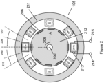
- the SRM 105 comprises a rotor 212 which rotates about an axis 200.
- the rotor 212 is, at any specific point in time, at an angle 205, which is the rotation of the rotor 212 relative to an axis A.
- the rotor 212 further comprises a plurality of magnetic elements 206.
- the magnetic elements 206 may be configured in or on the rotor 212 in any number of ways as is known in the art.
- the non-limiting example of Fig. 2 depicts the rotor 212 comprising eight magnetic elements 206, each spaced around the outer circumference of the rotor 212.
- the SRM 105 further comprises a stator 211, and a plurality of phases 201, 202, 203, 204 which are mechanically fixed to the stator 211.
- Each phase 201, 202, 203, 204 comprises a pair of poles 201a, 201b.
- Each pole 201b comprises a coiled wire 213, an input 214 and an output 215. The direction of the input 214 and the output 215 is relative to the coil 213 and may or may not be significant to the operation of the pole 201b or the phase 201.
- phase 201 is shown to have a pole-pair 201a, 201b, and only pole 201b is shown to have the coil 213, the input 214, and the output 215; however it is to be understood that each of the phases 201, 202, 203, 204 are in pole-pairs, and each of the poles comprise a coil, an input and an output.
- the magnetic elements 206 in the rotor 212 are configured to magnetically interact with the phases 201, 202, 203, 204 as the rotor 212 rotates.
- the power management unit 113 is configured to divide each pole into four periods: an initial motoring period 207, a final motoring period 208, an initial generation period 209, and a final generation period 210. By dividing each pole into these four periods, the power management unit 113 can effectively control the power, including the timing of power cycles, delivered to or received from a four phase SRM 105.
- the initial motoring period 207 begins once the element 206 is closer to the pole 201a than the previous pole 202. Between the initial motoring period 207 and the final motoring period 208, the element 206 moves rotationally towards the pole 201a. The final motoring period 208 ends as the magnetic element 206 is at a shortest rotational distance from the pole 201a.
- the initial generation period 209 begins when the element 206 is at the shortest rotational distance from the pole 201a. Between the initial generation period 209 and the final generation period 210, the element 206 moves rotationally away from the pole 201a. The final generation period 210 ends when the element 206 is closer to the pole 204 than the pole 201a.
- the SRM 105 may operate as a motor or as a generator.
- the phases 201, 202, 203, 204 receive electrical power from the power management unit 113, via power line 114, which causes the phases 201, 202, 203, 204 to generate a phase magnetic field.
- the phase magnetic fields interact with the magnetic fields associated with the magnetic elements 206, which develops a rotational force on the rotor 212 which causes the rotor 212 to rotate.
- each of the phases 201, 202, 203, 204 must receive electrical power, and thus generate a respective phase magnetic field, at a precise time.
- phase 201, 202, 203, 204 receives electrical power before the initial motoring period 207, then, as a result of the rotational distance between the element 206 and the respective phase, the phase magnetic field will not interact with the element magnetic field, and a rotational force will not be developed. As a result, the electrical power used to energise the respective phase is wasted. In this manner the SRM 105 would operate inefficiently as a motor.
- a phase 201, 202, 203, 204 receives electrical power after the final motoring period 208, for example from the initial generation period 209 until the final generation period 210, the rotational force developed on the rotor as a result of the interaction between the phase magnetic field and element magnetic field will be in an opposite direction compared to the rotation of the rotor 212. In this manner, the SRM 105 would operate ineffectively as a motor.
- the precise timing of the electrical power delivered to the phases 201, 202, 203, 204 is critical to the effective and efficient operation of the SRM 105 as a motor.
- the element magnetic fields energise the phases 201, 202, 203, 204 which generates electrical power.
- the phases 201, 202, 203, 204 are energised (and thus generate electrical power) from the initial generation period 209 to the final generation period 210. Rectification of the generated electrical power, via the power line 114 and the power management unit 113, requires precise timing control for efficient power conversion, in a similar manner to the motoring example provided above.
- the positional relationship between the elements 206 and the phases 201, 202, 203, 204 is critical to efficient and effective control of the SRM 105.
- the positional relationship is determined by the rotor angle 205.
- the timing requirements of the power delivered to or generated from the phases 201, 202, 203, 204 can be controlled such that the SRM 105 can operate efficiently and effectively in either a motoring or generation mode.
- the SRM 105 may operate in extreme temperatures and be subject to vibration, for example in aerospace applications, which may cause an electro-mechanical sensor to fail. This makes a need for determining the rotor angle without using an electro-mechanical sensor.
- FIG. 2 illustrates a phase and rotor arrangement at a first time interval T1.
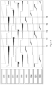
- Fig. 5 illustrates the rotor angle 205, the current in each phase 201, 202, 203, 204 and the processed data waveforms 501, 502, 503, 504 for each phase (as described in more detail below) from the first time interval T1 through to a final time interval T5.
- the rotor 212 completes one full rotation between the first time interval T1 and the final time interval T5.
- the power management unit 113 provides electrical power to the phase 203 which is beginning a final motoring period 208; and to the phase 202 which is in an initial motoring period 207.
- ripple torque in the rotor 212 can be reduced.
- phase 201 which is beginning an initial generation period 209, and to phase 204 which is in a final generation period 210.
- a high frequency injection (HFI) signal is a signal with a frequency considerably higher than the normal operating frequency of the electrical component. As a result of the high frequency component, a HFI signal does not interfere with the normal operation of the SRM 105.
- the current response of the high frequency voltage signal 108 is particularly dependent upon the inductance of the phase 201, 204, and the inductance of the phase 201, 204 changes as a result of flux linkage between the phase 201, 204 and a nearby element 206, which is a result of the rotational distance between the element 206 and the phase 201, 204. Therefore at any point in time, the current response as a result of the high frequency voltage signal 108 injected into a non-energised phase will be proportional to the rotor angle 205.
- R ph motor phase resistance
- i ph motor phase current
- ⁇ the flux linkage.
- Equation 3 shows how the voltage applied to each of the phases of the SRM 105 consists of three voltage drops.
- the term containing dt is large and the other two terms are negligible. This is because the other two terms contain the phase current i ph , which is zero when the phase is not energized.
- the injection unit 107 injects the signal 108 ( V ph ) into an input connection of the non-energized phases 201, 204 through the power line 114.
- the phases 201, 204 receive the signal 108, and the current changes di dt as the inductance ( L ( ⁇ )) in the phases 201, 204 changes proportionally to the rotor angle 205.
- the measurement unit 109 connected to the non-energized phase 201, 204 via the power line 114, determines the current and provides this information to the calculation unit 111 as the determined current 110.
- the calculation unit 111 applies an algorithm to the determined current 110 in order to provide a determined rotor angle 112.
- the calculation unit 111 applies the algorithm to the determined current 110 received from each non-energized phase 201, 204 simultaneously.
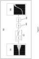
- the algorithm comprises a signal processing step 301, which signal processes the determined current 110 to provide processed data 302.
- the signal processing step 301 is done for each phase 201, 204 separately, illustrated by the parallel blocks 301a, 301b. Accordingly, two sets of processed data 302 are generated, however for conciseness only one is labelled.
- the signal processing step 301 comprises applying a first low pass filter 401 to the determined current 110 to provide a filtered current.
- the first low pass filter 401 is able to correct for any DC offset in the determined current 110.
- the first low pass filter 401 is applied to the determined (phase) current 110 to determine and remove any DC offset, and thereby provide a DC offset corrected phase current.
- An absolute value 403 of the filtered current (for example, the DC offset corrected phase current) is then calculated in order to provide an absolute current.
- the absolute value calculation converts any negative components of a signal into a positive component. Calculating the absolute value therefore rectifies the filtered current (DC offset corrected phase current).
- a second low pass filter 405 is then applied to the absolute current (for example, rectified and DC offset corrected phase current) to provide the processed data 302
- the second low pass filter 405 removes high frequency oscillations. Applying a second low pass filter 405 to the absolute current converts any high frequency signal components to a usable low frequency amplitude (for example, a smooth curve) and thereby provides the processed data 302.
- the low frequency amplitude processed data 302 can thus be used to establish rotor position.
- the processed data 302 is displayed for each phase 201, 202, 203, 204 as processed data waveforms 501, 502, 503, 504.
- the processed data waveforms 501, 502, 503, 504 are calculated in real time as discussed above.
- the corresponding processed data waveforms 501, 504 are at different positions within the waveform cycle.
- the waveform 504 is approximately halfway through the waveform 504 cycle, whereas the waveform 501 is at the start of the waveform 501 cycle.
- the two sets of processed data 302 provided from the non-energised phases 201, 204 are different, the difference corresponding to a difference between the relative position of a nearby element 206 and the phase 201, 204.
- the processed data 302 is converted in a conversion step 303 into an estimated rotor angle 304 for each phase 201, 204.
- the conversion step 303 is done for each phase 201, 204 separately, illustrated by the parallel blocks 303a, 303b.
- the conversion step 303 uses a look-up table which correlates the processed data 302 (in the form of a current reading in amps) into an estimated rotor angle 304 (in degrees or radians). Because the waveforms 501, 504 are at different positions, the look-up table uses a separate data set for each phase. Thus, the current readings from the waveforms 501, 504 will correlate to substantially the same rotor angle estimation. Accordingly, two estimated rotor angles 304 are generated.
- the two estimated rotor angles 304 are provided to an averaging step 305.
- the averaging step 305 takes an average (for example, an arithmetic average) of the two estimated rotor angles 304, and outputs a determined rotor angle 112a.
- This process allows the rotor angle 205 to be determined based on two separate positions within the SRM 105. This advantageously helps reduce error in the determined rotor angle 205.
- the determined rotor angle 112a is provided to a closed-loop Proportional-Integral (PI) tracker step 307, which reduces the error in the determined rotor angle 112a and provides a rotor angle with reduced error 112b.
- PI Proportional-Integral
- phase 203 ends its final motoring period 208 and becomes non-energised.
- phase 203 begins its initial generation period 209, wherein it receives the signal 108 for determining the rotor angle 205.
- phase 202 continues to be energised and provides a rotational force, as it moves from its initial motoring period 207 to its final motoring period 208.
- phase 201 continues to receive the signal 108 for determining the rotor angle 205, as it moves from its initial generation period 209 to its final generation period 210.
- phase 204 ends its final generation period 210, wherein it stops receiving the signal 108, and becomes energised to provide the rotational force in its initial motoring period 207.
- the energised phases and the phases receiving the signal 108 continue to change sequentially as the rotor 212 rotates.
- T1 to T5 any time period (T1 to T5) two phases are concurrently non-energised and receiving the signal 108, and two phases are energised providing the rotational force.
- the two phases will always be available to receive the (HFI) signal.
- the controller can readily be provided with information of the inductance of two separate phases to determine the rotor angle.
- the probability of two phases producing an error is lower than one phase producing an error.
- the two non-energised phases can provide information from two different locations within the machine. This allows the processing stage to receive more comprehensive information related to the inductance of the phases, which can be used to more accurately determine the rotor angle. This is because the error is greatest at the beginning and at the end of the measurement stage (and thus at the beginning and end of the processed data), because the gradient of the processed data curve is the lowest during this period.
- By having two phases in separate positions provide information on the rotor angle, only one phase will be at the beginning or end of the measurement stage. Thus, the overall determination of rotor angle is less susceptible to error and more accurate.
- two concurrently energised phases in the SRM advantageously provides the rotational force concurrently from two positions within the SRM, which reduces current ripple.
- the present invention thus allows for an SRM to operate in a manner where at any point in time two phases are used for torque production and two-phases are used for High Frequency Injection.
- the present invention therefore discloses a 2-phase torque 2-phase HFI pattern.
Landscapes
- Engineering & Computer Science (AREA)
- Power Engineering (AREA)
- Control Of Electric Motors In General (AREA)
Abstract
A controller for a switched reluctance machine, the machine comprising two concurrently energised phases and two concurrently non-energised phases. The controller is configured to, in an injection stage, inject a signal into the two non-energised phases; in a measurement stage, determine a current in each of the two non-energised phases; and in a calculation stage, apply an algorithm to the determined currents to determine a rotor angle.
Description
- This application relates to a controller for a switched reluctance machine.
- Switched reluctance machines (SRMs) include a plurality of phases, a stator and a rotor, and may operate as a motor or a generator. In both operational modes, it is critical to know the angle of the rotor for control purposes, which may be determined by an electro-mechanical sensor. In some environments, for example aerospace applications, the machine may operate in extreme temperatures and be subject to vibration sufficient to cause the electro-mechanical sensor to fail. As a result, there is a need for determining the rotor angle without using an electro-mechanical sensor.
- In a first aspect of the invention, there is provided a controller for a switched reluctance machine, the machine comprising two concurrently energised phases and two concurrently non-energised phases, the controller configured to in an injection stage, inject a signal into the two non-energised phases; in a measurement stage, determine the current in each of the two non-energised phases; and in a calculation stage, apply an algorithm to the determined currents to determine a rotor angle.
- By providing the injection signal (e.g. a high frequency injection signal) to the two concurrently non-energised phases, and calculating the rotor angle based on the two-non energised phases, the determination of the rotor angle according to the present invention is more reliable.
- By having two phases providing information for rotor angle determination, from different locations within the machine, the overall determination of rotor angle is less susceptible to error as any noise from one phase, for example due to Electro Magnetic Interference (EMI), can be compensated for by the other phase which may not be subject to the EMI.
- In some examples, the switched reluctance machine comprises a rotor having a rotation cycle, and is configured such that at any point during the rotation cycle two phases of the machine are concurrently non-energised.
- In some examples, in the injection stage, the signal is injected into each of the two non-energised phases such that two phases of the machine are receiving the injection signal at any point during the rotation cycle.
- In some examples the algorithm comprises signal processing the determined current of each phase to provide processed data for each phase; converting the processed data into an estimated rotor angle for each phase; and averaging the estimated angle from each phase to determine the rotor angle.
- In some examples the signal processing comprises applying a first low pass filter to the determined current to provide a filtered current; calculating an absolute value of the filtered current to provide an absolute current; and applying a second low pass filter to the absolute current to provide the processed data.
- In some examples the converting comprises using a look-up table to convert the processed data into an estimated rotor angle.
- In some examples the algorithm further comprises providing the determined rotor angle to a closed loop PI tracker. A PI tracker is an effective way of reducing the error in the rotor angle, making the tracking smoother, and filtering out sampling errors.
- In some examples the signal has a duty cycle of less than 50%. In some examples, the signal has a frequency of 30kHz. Using a frequency that is considerably higher than the normal operating frequency of the machine ensures minimal torque ripple and low levels of acoustic noise.
- In some examples the controller is further configured to, in a power management stage, configure the flow of electrical power to or from the machine.
- In some examples the controller is further configured to, in the calculation stage, provide the power management stage with the determined rotor angle; and in the power management stage, control the flow of electrical power to or from the machine based on the rotor angle.
- In some examples the controller is configured to, in the power management stage, control the flow of electrical power by controlling a timing of the electrical power supplied to each phase, or a rectification of the electrical power received by each phase.
- In some examples the switched reluctance machine comprises four phases; wherein in the power management stage, the controller is configured to control the flow of electrical power such that an initial motoring period of a first phase occurs concurrently with: a final generation period of a second phase, an initial generation period of a third phase, and a final motoring period of a fourth phase.
- In some examples the controller is configured to control the machine as a motor; wherein in the power management stage, the controller is configured to control the flow of electrical power to energise each phase during a motoring period to produce a motoring torque, and to energise the phases such that two phases are concurrently non-energised; and wherein in the injection stage the controller is configured to inject each phase during an initial generation period and a final generation period.
- In some examples a rotor of the machine is configured to energise each phase during a generation period to generate electrical power, and the machine is configured such that two phases are concurrently non-energised; and the controller is configured to control the machine as a generator; and in the injection stage, the controller is configured to inject each phase during an initial motoring period and a final motoring period.
- In a second aspect of the invention there is provided a switched reluctance machine comprising a rotor comprising a plurality of magnetic elements; a stator comprising two concurrently non-energised phases; and the controller of the first aspect configured to control the machine as a motor or as a generator.
- In a third aspect of the invention there is provided an aircraft comprising the switched reluctance machine of the second aspect.
- In some examples, when the controller is configured to control the machine as a motor, the machine is connected to a propeller assembly and provides a propulsive force to propel the aircraft; and when the controller is configured to control the machine as a generator, the machine is connected to a turbine and provides an output of electrical energy for the aircraft.
- In a fourth aspect of the invention, there is provided a method for controlling a switched reluctance machine, the machine comprising two concurrently non-energised phases; the method comprising injecting a signal into the two non-energised phases; determining the current in each of the two non-energised phases; and applying an algorithm to the determined currents to determine the rotor angle.
- In some examples the method further comprises energising the phases such that two phases are concurrently non-energised.
- The switched reluctance machine of the second aspect and the aircraft of the third aspect may each comprise any of the features of the examples described with respect to the first aspect. The method of the fourth aspect may include any functional steps described in relation to the examples of the first and second aspects.
- Various examples will now be described with reference to the accompanying drawings in which:
-
Figure 1 shows a schematic overview of an aircraft, a controller, a switched reluctance machine and an aircraft component. -
Figure 2 shows a cross section of an exemplary switched reluctance machine. -
Figure 3 shows a block diagram of the calculation stage. -
Figure 4 shows a block diagram of signal processing. -
Figure 5 shows a graph of the phase currents and processed data of an exemplary four phase motor. - With reference to
Fig. 1 , anaircraft 101 comprises a switched reluctance machine (SRM) 105, acontroller 103, and anaircraft component 115. The controller may comprise apower management unit 113. - The SRM 105 is mechanically coupled to the
aircraft component 115, which may be, for example, a turbine and/or a propeller assembly comprising, for example, a propeller and a gearbox. The SRM 105 can be configured to operate as a motor or as a generator. The SRM 105 may be switchable between the two operating modes, depending on the requirements of theaircraft 101. - The
SRM 105 comprises a stator, a rotor, and a plurality of phases, which are described in more detail below. - The
power management unit 113 is configured to control the flow of electrical power to or from the SRM 105 via apower line 114. Thepower line 114 includes a plurality of connections, each connection connecting to a phase or a pole of theSRM 105. A phase of theSRM 105 may comprise two poles. Each connection in thepower line 114 may be connected to a phase, which drives two poles simultaneously, or connected to a specific pole within a phase. In this manner, each connection may be connected to a phase or a pole. - Each connection is able to transfer electrical power with a high voltage and/or current, for example hundreds of volts and/or tens of amps. Each connection includes an
input 214 and an output 215 (as shown inFig. 2 and described in more detail below), wherein the phase or pole of theSRM 105 is connected between the input and the output, such that current travels towards the phase or pole at the input and away from the phase or pole at the output. - The
controller 103 comprises aninjection unit 107, ameasurement unit 109, and acalculation unit 111. The controller may also comprise thepower management unit 113. - The
injection unit 107 is configured to inject asignal 108 into the SRM 105 via thepower line 114. Theinjection unit 107 is connected to each phase of theSRM 105 via the input connections within thepower line 114, such that theinjection unit 107 can inject thesignal 108 into each individual phase of theSRM 105 separately. Each phase of theSRM 105 may thus receive asignal 108 at a specific time interval. - The
signal 108 may be a high frequency injection (HFI). A HFI signal is a voltage waveform with a frequency significantly higher than a normal operating frequency of an electrical component (for example thesignal 108 would be at a frequency significantly higher than the frequency of the voltage and current in thepower line 114 during a normal operating condition of theSRM 105, as described in more detail below). - The frequency and duty cycle of the
signal 108 are two parameters that may be customized for an application. Thesignal 108 may be a square wave with a duty cycle of less than 50%. Thesignal 108 may have a frequency of 30kHz. The voltage of thesignal 108 may be at the same voltage level of the power supplied to theSRM 105. - The
measurement unit 109 is connected to theSRM 105 via thepower line 114. Themeasurement unit 109 is connected to each phase of theSRM 105 via the connections in thepower line 114, such that themeasurement unit 109 can determine a high frequency current on each individual phase of theSRM 105 separately. The high frequency current is a result of thesignal 108 injected into the phase of theSRM 105. Thus, when thesignal 108 is injected into a phase of theSRM 105, themeasurement unit 109 can determine the current as a result of the injectedsignal 108. Themeasurement unit 109 outputs the determined current 110 to thecalculation unit 111. - The
calculation unit 111 receives the determined current 110 and determines therotor angle 112, by applying an algorithm which is described in more detail below. Therotor angle 112 is received by thepower management unit 113 and used to control the flow of power to or from theSRM 105. - As shown in
Fig. 2 , theSRM 105 comprises arotor 212 which rotates about anaxis 200. Therotor 212 is, at any specific point in time, at anangle 205, which is the rotation of therotor 212 relative to an axis A. Therotor 212 further comprises a plurality ofmagnetic elements 206. Themagnetic elements 206 may be configured in or on therotor 212 in any number of ways as is known in the art. The non-limiting example ofFig. 2 depicts therotor 212 comprising eightmagnetic elements 206, each spaced around the outer circumference of therotor 212. - The
SRM 105 further comprises astator 211, and a plurality ofphases stator 211. Eachphase poles 201a, 201b. Eachpole 201b comprises acoiled wire 213, aninput 214 and anoutput 215. The direction of theinput 214 and theoutput 215 is relative to thecoil 213 and may or may not be significant to the operation of thepole 201b or thephase 201. InFig. 2 phase 201 is shown to have a pole-pair 201a, 201b, and onlypole 201b is shown to have thecoil 213, theinput 214, and theoutput 215; however it is to be understood that each of thephases - The
magnetic elements 206 in therotor 212 are configured to magnetically interact with thephases rotor 212 rotates. - The
power management unit 113 is configured to divide each pole into four periods: aninitial motoring period 207, afinal motoring period 208, aninitial generation period 209, and afinal generation period 210. By dividing each pole into these four periods, thepower management unit 113 can effectively control the power, including the timing of power cycles, delivered to or received from a fourphase SRM 105. - The
initial motoring period 207 begins once theelement 206 is closer to the pole 201a than theprevious pole 202. Between theinitial motoring period 207 and thefinal motoring period 208, theelement 206 moves rotationally towards the pole 201a. Thefinal motoring period 208 ends as themagnetic element 206 is at a shortest rotational distance from the pole 201a. Theinitial generation period 209 begins when theelement 206 is at the shortest rotational distance from the pole 201a. Between theinitial generation period 209 and thefinal generation period 210, theelement 206 moves rotationally away from the pole 201a. Thefinal generation period 210 ends when theelement 206 is closer to thepole 204 than the pole 201a. - The
SRM 105 may operate as a motor or as a generator. - In a motoring mode, the
phases power management unit 113, viapower line 114, which causes thephases magnetic elements 206, which develops a rotational force on therotor 212 which causes therotor 212 to rotate. - For the rotational force to be efficiently and effectively developed, each of the
phases - If a
phase initial motoring period 207, then, as a result of the rotational distance between theelement 206 and the respective phase, the phase magnetic field will not interact with the element magnetic field, and a rotational force will not be developed. As a result, the electrical power used to energise the respective phase is wasted. In this manner theSRM 105 would operate inefficiently as a motor. - If a
phase final motoring period 208, for example from theinitial generation period 209 until thefinal generation period 210, the rotational force developed on the rotor as a result of the interaction between the phase magnetic field and element magnetic field will be in an opposite direction compared to the rotation of therotor 212. In this manner, theSRM 105 would operate ineffectively as a motor. - Accordingly, the precise timing of the electrical power delivered to the
phases SRM 105 as a motor. - In a generation mode, the element magnetic fields energise the
phases phases initial generation period 209 to thefinal generation period 210. Rectification of the generated electrical power, via thepower line 114 and thepower management unit 113, requires precise timing control for efficient power conversion, in a similar manner to the motoring example provided above. - In both operating modes, the positional relationship between the
elements 206 and thephases SRM 105. The positional relationship is determined by therotor angle 205. Thus, by accurately determining therotor angle 205, the timing requirements of the power delivered to or generated from thephases SRM 105 can operate efficiently and effectively in either a motoring or generation mode. - As discussed in the background section, the
SRM 105 may operate in extreme temperatures and be subject to vibration, for example in aerospace applications, which may cause an electro-mechanical sensor to fail. This makes a need for determining the rotor angle without using an electro-mechanical sensor. - Referring to
Fig. 2 andFig. 5 , an example of a fourphase SRM 105 in a motoring mode is disclosed. In particular,Fig. 2 illustrates a phase and rotor arrangement at a first time interval T1.Fig. 5 illustrates therotor angle 205, the current in eachphase data waveforms rotor 212 completes one full rotation between the first time interval T1 and the final time interval T5. - Between the time T1 and T2, the
power management unit 113 provides electrical power to thephase 203 which is beginning afinal motoring period 208; and to thephase 202 which is in aninitial motoring period 207. By providing electrical power to energise two phases simultaneously, ripple torque in therotor 212 can be reduced. - In order to determine the
rotor angle 205, thesignal 108 is injected into two non-energised phases. A non-energised phase may be a phase which is neither receiving nor generating electrical power. At time T1, phases 201, 204 are non-energised. Theinjection unit 107 provides thesignal 108 tophase 201 which is beginning aninitial generation period 209, and to phase 204 which is in afinal generation period 210. - As mentioned above, a high frequency injection (HFI) signal is a signal with a frequency considerably higher than the normal operating frequency of the electrical component. As a result of the high frequency component, a HFI signal does not interfere with the normal operation of the
SRM 105. By injecting a highfrequency voltage signal 108 into the twonon-energised phases rotor angle 205 can be determined. This is because the current response of the highfrequency voltage signal 108 is particularly dependent upon the inductance of thephase phase phase nearby element 206, which is a result of the rotational distance between theelement 206 and thephase frequency voltage signal 108 injected into a non-energised phase will be proportional to therotor angle 205. - The equation that applies for the phase voltage of an SRM is shown in Equation 1:

- Where Rph is motor phase resistance, iph is motor phase current and Ψ is the flux linkage. The flux linkage can be defined in equation 2:
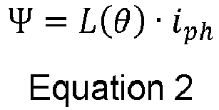
- Where L(θ) is the phase inductance. Taking into account Equation 2, Equation 1 becomes:

- Equation 3 shows how the voltage applied to each of the phases of the
SRM 105 consists of three voltage drops. Upon injection of the highfrequency voltage signal 108, the term containing dt is large and the other two terms are negligible. This is because the other two terms contain the phase current iph , which is zero when the phase is not energized. - Accordingly, the
injection unit 107 injects the signal 108 (Vph ) into an input connection of thenon-energized phases power line 114. Thephases signal 108, and the current changes
phases rotor angle 205. Themeasurement unit 109, connected to thenon-energized phase power line 114, determines the current and provides this information to thecalculation unit 111 as the determined current 110. - Referring to
Fig. 3 , thecalculation unit 111 applies an algorithm to the determined current 110 in order to provide adetermined rotor angle 112. Thecalculation unit 111 applies the algorithm to the determined current 110 received from eachnon-energized phase - The algorithm comprises a
signal processing step 301, which signal processes the determined current 110 to provide processeddata 302. Thesignal processing step 301 is done for eachphase parallel blocks data 302 are generated, however for conciseness only one is labelled. - Referring to
Fig. 4 , thesignal processing step 301 comprises applying a firstlow pass filter 401 to the determined current 110 to provide a filtered current. The firstlow pass filter 401 is able to correct for any DC offset in the determined current 110. Thus, the firstlow pass filter 401 is applied to the determined (phase) current 110 to determine and remove any DC offset, and thereby provide a DC offset corrected phase current. - An
absolute value 403 of the filtered current (for example, the DC offset corrected phase current) is then calculated in order to provide an absolute current. The absolute value calculation converts any negative components of a signal into a positive component. Calculating the absolute value therefore rectifies the filtered current (DC offset corrected phase current). - A second
low pass filter 405 is then applied to the absolute current (for example, rectified and DC offset corrected phase current) to provide the processeddata 302 The secondlow pass filter 405 removes high frequency oscillations. Applying a secondlow pass filter 405 to the absolute current converts any high frequency signal components to a usable low frequency amplitude (for example, a smooth curve) and thereby provides the processeddata 302. The low frequency amplitude processeddata 302 can thus be used to establish rotor position. - In
Fig. 5 , the processeddata 302 is displayed for eachphase data waveforms data waveforms non-energised phase 201 is in theinitial generation period 209, and thenon-energised phase 204 is in thefinal generation period 210, the corresponding processeddata waveforms waveform 504 is approximately halfway through thewaveform 504 cycle, whereas thewaveform 501 is at the start of thewaveform 501 cycle. In this manner, the two sets of processeddata 302 provided from thenon-energised phases nearby element 206 and thephase - Referring again to
Fig. 3 , the processeddata 302 is converted in aconversion step 303 into an estimatedrotor angle 304 for eachphase conversion step 303 is done for eachphase parallel blocks conversion step 303 uses a look-up table which correlates the processed data 302 (in the form of a current reading in amps) into an estimated rotor angle 304 (in degrees or radians). Because thewaveforms waveforms - The two estimated rotor angles 304 are provided to an averaging
step 305. The averagingstep 305 takes an average (for example, an arithmetic average) of the two estimated rotor angles 304, and outputs adetermined rotor angle 112a. - This process allows the
rotor angle 205 to be determined based on two separate positions within theSRM 105. This advantageously helps reduce error in thedetermined rotor angle 205. - In some embodiments, the
determined rotor angle 112a is provided to a closed-loop Proportional-Integral (PI)tracker step 307, which reduces the error in thedetermined rotor angle 112a and provides a rotor angle with reduced error 112b. - Referring to
Fig. 5 , between the time T1 and T2, twophases phases signal 108 for determining therotor angle 205. Before time T2,phase 203 ends itsfinal motoring period 208 and becomes non-energised. Attime T2 phase 203 begins itsinitial generation period 209, wherein it receives thesignal 108 for determining therotor angle 205. - At
time T2 phase 202 continues to be energised and provides a rotational force, as it moves from itsinitial motoring period 207 to itsfinal motoring period 208. At thesame time phase 201 continues to receive thesignal 108 for determining therotor angle 205, as it moves from itsinitial generation period 209 to itsfinal generation period 210. At the same time,phase 204 ends itsfinal generation period 210, wherein it stops receiving thesignal 108, and becomes energised to provide the rotational force in itsinitial motoring period 207. - As illustrated in
Fig. 5 , the energised phases and the phases receiving thesignal 108 continue to change sequentially as therotor 212 rotates. During any time period (T1 to T5) two phases are concurrently non-energised and receiving thesignal 108, and two phases are energised providing the rotational force. However, during no time period is anyphase same period data 302 always comes from two separate phases at different rotational positions. This can be seen in thewaveforms waveforms - In the present invention, because two phases are concurrently non-energised, the two phases will always be available to receive the (HFI) signal. As a result, the controller can readily be provided with information of the inductance of two separate phases to determine the rotor angle. The probability of two phases producing an error is lower than one phase producing an error. By providing the signal to the two concurrently non-energised phases the determination of the rotor angle according to the present invention is more reliable.
- Furthermore, the two non-energised phases can provide information from two different locations within the machine. This allows the processing stage to receive more comprehensive information related to the inductance of the phases, which can be used to more accurately determine the rotor angle. This is because the error is greatest at the beginning and at the end of the measurement stage (and thus at the beginning and end of the processed data), because the gradient of the processed data curve is the lowest during this period. By having two phases in separate positions provide information on the rotor angle, only one phase will be at the beginning or end of the measurement stage. Thus, the overall determination of rotor angle is less susceptible to error and more accurate.
- Additionally, two concurrently energised phases in the SRM advantageously provides the rotational force concurrently from two positions within the SRM, which reduces current ripple.
- The present invention thus allows for an SRM to operate in a manner where at any point in time two phases are used for torque production and two-phases are used for High Frequency Injection. The present invention therefore discloses a 2-phase torque 2-phase HFI pattern.
- Various aspects of the apparatus disclosed in the various embodiments may be used alone, in combination, or in a variety of arrangements not specifically discussed in the embodiments described in the foregoing and this disclosure is therefore not limited in its application to the details and arrangement of components set forth in the foregoing description or illustrated in the drawings. For example, aspects described in one embodiment may be combined in any manner with aspects described in other embodiments. Although particular embodiments have been shown and described, it will be obvious to those skilled in the art that changes and modifications may be made without departing from this invention in its broader aspects. The scope of the following claims should not be limited by the embodiments set forth in the examples, but should be given the broadest reasonable interpretation consistent with the description as a whole.
Claims (15)
- A controller for a switched reluctance machine, the machine comprising two concurrently energised phases and two concurrently non-energised phases, the controller configured to:in an injection stage, inject a signal into the two non-energised phases;in a measurement stage, determine a current in each of the two non-energised phases; andin a calculation stage, apply an algorithm to the determined currents to determine a rotor angle.
- The controller of claim 1, wherein the algorithm comprises:signal processing the determined current of each phase to provide processed data for each phase;converting the processed data into an estimated rotor angle for each phase; andaveraging the estimated angle from each phase to determine the rotor angle.
- The controller of claim 2, wherein the signal processing comprises:applying a first low pass filter to the determined current to provide a filtered current;calculating an absolute value of the filtered current to provide an absolute current; andapplying a second low pass filter to the absolute current to provide the processed data.
- The controller of claim 2 or 3, wherein the converting comprises:
using a look-up table to convert the processed data into an estimated rotor angle. - The controller of claims 2 to 4, wherein the algorithm further comprises:
providing the determined rotor angle to a closed loop PI tracker. - The controller of any preceding claim, wherein the signal has a duty cycle of less than 50% and/or a frequency of 30kHz.
- The controller of any preceding claim, further configured to:in the calculation stage, provide a power management stage with the determined rotor angle; andin the power management stage, control the flow of electrical power to or from the machine based on the rotor angle.
- The controller of claim 7, further configured to:
in the power management stage, control the flow of electrical power by controlling:a timing of the electrical power supplied to each phase, ora rectification of the electrical power received from each phase. - The controller of claim 7 or 8, wherein in the power management stage, the controller is configured to control the flow of electrical power such that an initial motoring period of a first phase occurs concurrently with:a final generation period of a second phase,an initial generation period of a third phase, anda final motoring period of a fourth phase.
- The controller of claims 7 to 9, whereinthe controller is configured to control the machine as a motor;wherein in the power management stage the controller is configured to control the flow of electrical power to energise each phase during a motoring period to produce a motoring torque, and to energise the phases such that two phases are concurrently non-energised; andwherein in the injection stage the controller is configured to inject each phase during an initial generation period and a final generation period.
- The controller of claims 7 to 9, wherein a rotor of the machine is configured to energise each phase during a generation period to generate electrical power, and wherein the machine is configured such that two phases are concurrently non-energised; whereinthe controller is configured to control the machine as a generator;in the injection stage the controller is configured to inject each phase during an initial motoring period and a final motoring period.
- A switched reluctance machine comprising:a rotor comprising a plurality of inductive or magnetic elements;a stator comprising two concurrently non-energised phases and two concurrently energised phases; andthe controller of claims 1 to 11 configured to control the machine as a motor or as a generator.
- An aircraft comprising the switched reluctance machine of claim 12.
- The aircraft of claim 13, wherein:when the controller is configured to control the machine as a motor, the machine is connected to a propeller assembly and provides a propulsive force to propel the aircraft;when the controller is configured to control the machine as a generator, the machine is connected to a turbine, and provides an output of electrical energy for the aircraft.
- A method for controlling a switched reluctance machine, the machine comprising two concurrently energised phases and two concurrently non-energised phases; the method comprising:injecting a signal into the two non-energised phases;determining the current in each of the two non-energised phases; andapplying an algorithm to the determined currents to determine the rotor angle.
Priority Applications (2)
| Application Number | Priority Date | Filing Date | Title |
|---|---|---|---|
| EP23156917.9A EP4418529A1 (en) | 2023-02-15 | 2023-02-15 | Controller for a switched reluctance machine |
| US18/395,427 US12614999B2 (en) | 2023-02-15 | 2023-12-22 | Controller for a switched reluctance machine |
Applications Claiming Priority (1)
| Application Number | Priority Date | Filing Date | Title |
|---|---|---|---|
| EP23156917.9A EP4418529A1 (en) | 2023-02-15 | 2023-02-15 | Controller for a switched reluctance machine |
Publications (1)
| Publication Number | Publication Date |
|---|---|
| EP4418529A1 true EP4418529A1 (en) | 2024-08-21 |
Family
ID=85251743
Family Applications (1)
| Application Number | Title | Priority Date | Filing Date |
|---|---|---|---|
| EP23156917.9A Pending EP4418529A1 (en) | 2023-02-15 | 2023-02-15 | Controller for a switched reluctance machine |
Country Status (2)
| Country | Link |
|---|---|
| US (1) | US12614999B2 (en) |
| EP (1) | EP4418529A1 (en) |
Citations (2)
| Publication number | Priority date | Publication date | Assignee | Title |
|---|---|---|---|---|
| US5600218A (en) * | 1995-09-11 | 1997-02-04 | George H. Holling | Sensorless commutation position detection for brushless motors |
| FR2959279A1 (en) * | 2010-04-23 | 2011-10-28 | Hispano Suiza Sa | Method for controlling starter-generator of turbine engine of aircraft during starting phase of turbine engine, involves generating starting torque without contribution of rotor inductor of electric machine |
Family Cites Families (20)
| Publication number | Priority date | Publication date | Assignee | Title |
|---|---|---|---|---|
| US5140243A (en) * | 1991-09-13 | 1992-08-18 | General Electric Company | Discrete position estimator for a switched reluctance machine using a flux-current map comparator |
| US5525886A (en) | 1994-06-23 | 1996-06-11 | General Electric Company | Low speed position estimator for switched reluctance machine using flux/current model |
| US5864217A (en) * | 1997-05-08 | 1999-01-26 | General Electric Company | Switched reluctance machine with toothed-wheel rotor sensor |
| GB9828186D0 (en) | 1998-12-21 | 1999-02-17 | Switched Reluctance Drives Ltd | Control of switched reluctance machines |
| US6650082B1 (en) | 2000-07-27 | 2003-11-18 | Texas Instruments Incorporated | Fast rotor position detection apparatus and method for disk drive motor at standstill |
| WO2004049552A1 (en) * | 2002-11-28 | 2004-06-10 | Matsushita Electric Industrial Co., Ltd. | Method and apparatus for estimating rotor position and for sensorless control of a switched reluctance motor |
| KR101152083B1 (en) | 2003-04-24 | 2012-06-11 | 니덱 에스알 드라이브즈 리미티드 | Rotor position detector of a switched reluctance machine |
| US8253360B2 (en) | 2009-07-15 | 2012-08-28 | GM Global Technology Operations LLC | Vector controlled motor drive system implementing pulse width modulated (PWM) waveforms |
| WO2013105506A1 (en) * | 2012-01-11 | 2013-07-18 | Nidec Corporation | Motor Controller |
| EP3016275A1 (en) * | 2014-10-31 | 2016-05-04 | Siemens Aktiengesellschaft | Method for determining a rotor frequency and/or a rotor angle of a rotor of a reluctance machine, control device and drive assembly |
| JP6451984B2 (en) * | 2014-12-26 | 2019-01-16 | 日本電産株式会社 | Motor controller |
| WO2016189547A1 (en) * | 2015-05-25 | 2016-12-01 | Aditya Auto Products & Engg. (I) Pvt. Ltd. | Switched reluctance machine (srm) with parallel flux path |
| EP3125424A1 (en) | 2015-07-28 | 2017-02-01 | Perkins Engines Company Limited | Method to control a switched reluctance motor |
| CN206252509U (en) * | 2016-08-17 | 2017-06-16 | 上海新黄浦医疗器械有限公司 | A kind of electric-control system of digital galactophore X-ray production apparatus |
| DE102016123335A1 (en) | 2016-12-02 | 2018-06-07 | Miele & Cie. Kg | Method and drive unit for controlling a switched reluctance motor |
| DE102016123715A1 (en) | 2016-12-07 | 2018-06-07 | Airbus Defence and Space GmbH | Control device for a polyphase motor and method for driving a polyphase motor |
| WO2019056072A1 (en) | 2017-09-22 | 2019-03-28 | Janislav Sega | System and method for controlling a motor |
| US10978980B2 (en) * | 2019-07-08 | 2021-04-13 | Karma Automotive Llc | Switched reluctance motor control |
| US11411570B1 (en) * | 2021-10-29 | 2022-08-09 | Hangzhou Geo-Chip Technology Co., Ltd. | Multi modulus frequency divider and electronic device |
| US11993368B2 (en) * | 2022-04-29 | 2024-05-28 | Beta Air, Llc | Hybrid electric vertical takeoff and landing aircraft |
-
2023
- 2023-02-15 EP EP23156917.9A patent/EP4418529A1/en active Pending
- 2023-12-22 US US18/395,427 patent/US12614999B2/en active Active
Patent Citations (2)
| Publication number | Priority date | Publication date | Assignee | Title |
|---|---|---|---|---|
| US5600218A (en) * | 1995-09-11 | 1997-02-04 | George H. Holling | Sensorless commutation position detection for brushless motors |
| FR2959279A1 (en) * | 2010-04-23 | 2011-10-28 | Hispano Suiza Sa | Method for controlling starter-generator of turbine engine of aircraft during starting phase of turbine engine, involves generating starting torque without contribution of rotor inductor of electric machine |
Non-Patent Citations (1)
| Title |
|---|
| KIM JONGWAN ET AL: "Position Sensorless Control of Switched Reluctance Motor Drives Without Pre-stored Magnetic Characteristics", 2018 IEEE ENERGY CONVERSION CONGRESS AND EXPOSITION (ECCE), IEEE, 23 September 2018 (2018-09-23), pages 1755 - 1761, XP033463787, DOI: 10.1109/ECCE.2018.8557719 * |
Also Published As
| Publication number | Publication date |
|---|---|
| US12614999B2 (en) | 2026-04-28 |
| US20240275322A1 (en) | 2024-08-15 |
Similar Documents
| Publication | Publication Date | Title |
|---|---|---|
| French et al. | Direct torque control of permanent magnet drives | |
| CN101567660B (en) | Motor control device and generator control device | |
| CN101873096B (en) | Method for determining the position of the flux vector of a motor | |
| JP4909797B2 (en) | Motor control device | |
| EP2232696B1 (en) | Control of electrical machines | |
| US7072778B2 (en) | Method and system for determining a rotor position in a wound field DC motor | |
| EP2232695B1 (en) | Control of electrical machines | |
| US8766571B2 (en) | Method and apparatus for controlling an electrical machine | |
| KR100795382B1 (en) | System and method for controlling a permanent magnet rotating machine in a sensorless manner | |
| EP2258043B1 (en) | Sensorless control of salient-pole machines | |
| CN103199789A (en) | Methods and systems for sensorless control of an electric motor | |
| WO1994011945A1 (en) | Method of observer-based control of permanent-magnet synchronous motors | |
| JP2008048541A (en) | Method and device for controlling feedback of electric motor | |
| KR20100042255A (en) | A control system without position sensors for a synchronous electric motor | |
| US7095205B2 (en) | System and method for inductance based position encoding sensorless SRM drives | |
| Chen et al. | Self-sensing control of permanent-magnet synchronous machines with multiple saliencies using pulse-voltage-injection | |
| EP3258594B1 (en) | Controlling a multiple-set electrical machine | |
| CN116868500A (en) | Methods of controlling brushless permanent magnet motors | |
| EP3736954A1 (en) | Predictive pulse width modulation for an open delta h-bridge driven high efficiency ironless permanent magnet machine | |
| EP1646138B1 (en) | Device for estimating pole position of synchronous motor | |
| US20140265958A1 (en) | Control Device and Method for Controlling an Induction Machine | |
| US12614999B2 (en) | Controller for a switched reluctance machine | |
| JP5652701B2 (en) | Motor drive control device | |
| Riyadi | A simple method to control the excitation angle for switched reluctance motor | |
| CN119343863A (en) | Drive control device, drive control system, and state estimation method |
Legal Events
| Date | Code | Title | Description |
|---|---|---|---|
| PUAI | Public reference made under article 153(3) epc to a published international application that has entered the european phase |
Free format text: ORIGINAL CODE: 0009012 |
|
| STAA | Information on the status of an ep patent application or granted ep patent |
Free format text: STATUS: THE APPLICATION HAS BEEN PUBLISHED |
|
| AK | Designated contracting states |
Kind code of ref document: A1 Designated state(s): AL AT BE BG CH CY CZ DE DK EE ES FI FR GB GR HR HU IE IS IT LI LT LU LV MC ME MK MT NL NO PL PT RO RS SE SI SK SM TR |
|
| STAA | Information on the status of an ep patent application or granted ep patent |
Free format text: STATUS: REQUEST FOR EXAMINATION WAS MADE |
|
| 17P | Request for examination filed |
Effective date: 20250130 |