EP4418518A1 - Three-level zeta asymmetrical half-bridge - Google Patents
Three-level zeta asymmetrical half-bridge Download PDFInfo
- Publication number
- EP4418518A1 EP4418518A1 EP23156581.3A EP23156581A EP4418518A1 EP 4418518 A1 EP4418518 A1 EP 4418518A1 EP 23156581 A EP23156581 A EP 23156581A EP 4418518 A1 EP4418518 A1 EP 4418518A1
- Authority
- EP
- European Patent Office
- Prior art keywords
- voltage
- bridge
- transformer
- switching elements
- zeta
- Prior art date
- Legal status (The legal status is an assumption and is not a legal conclusion. Google has not performed a legal analysis and makes no representation as to the accuracy of the status listed.)
- Pending
Links
- 238000004804 winding Methods 0.000 claims description 64
- 239000003990 capacitor Substances 0.000 claims description 56
- 238000000034 method Methods 0.000 claims description 12
- 238000001914 filtration Methods 0.000 claims description 4
- 230000003068 static effect Effects 0.000 description 13
- 230000008901 benefit Effects 0.000 description 12
- 230000003071 parasitic effect Effects 0.000 description 4
- 238000006243 chemical reaction Methods 0.000 description 3
- 238000001816 cooling Methods 0.000 description 3
- 230000010363 phase shift Effects 0.000 description 3
- 239000004065 semiconductor Substances 0.000 description 3
- 230000002457 bidirectional effect Effects 0.000 description 2
- 238000005516 engineering process Methods 0.000 description 2
- 238000002955 isolation Methods 0.000 description 2
- 230000009286 beneficial effect Effects 0.000 description 1
- 230000000295 complement effect Effects 0.000 description 1
- 230000000694 effects Effects 0.000 description 1
- 238000005549 size reduction Methods 0.000 description 1
Images










Classifications
-
- H—ELECTRICITY
- H02—GENERATION; CONVERSION OR DISTRIBUTION OF ELECTRIC POWER
- H02M—APPARATUS FOR CONVERSION BETWEEN AC AND AC, BETWEEN AC AND DC, OR BETWEEN DC AND DC, AND FOR USE WITH MAINS OR SIMILAR POWER SUPPLY SYSTEMS; CONVERSION OF DC OR AC INPUT POWER INTO SURGE OUTPUT POWER; CONTROL OR REGULATION THEREOF
- H02M3/00—Conversion of DC power input into DC power output
- H02M3/22—Conversion of DC power input into DC power output with intermediate conversion into AC
- H02M3/24—Conversion of DC power input into DC power output with intermediate conversion into AC by static converters
- H02M3/28—Conversion of DC power input into DC power output with intermediate conversion into AC by static converters using discharge tubes with control electrode or semiconductor devices with control electrode to produce the intermediate AC
- H02M3/325—Conversion of DC power input into DC power output with intermediate conversion into AC by static converters using discharge tubes with control electrode or semiconductor devices with control electrode to produce the intermediate AC using devices of a triode or a transistor type requiring continuous application of a control signal
- H02M3/335—Conversion of DC power input into DC power output with intermediate conversion into AC by static converters using discharge tubes with control electrode or semiconductor devices with control electrode to produce the intermediate AC using devices of a triode or a transistor type requiring continuous application of a control signal using semiconductor devices only
- H02M3/33569—Conversion of DC power input into DC power output with intermediate conversion into AC by static converters using discharge tubes with control electrode or semiconductor devices with control electrode to produce the intermediate AC using devices of a triode or a transistor type requiring continuous application of a control signal using semiconductor devices only having several active switching elements
- H02M3/33571—Half-bridge at primary side of an isolation transformer
-
- H—ELECTRICITY
- H02—GENERATION; CONVERSION OR DISTRIBUTION OF ELECTRIC POWER
- H02M—APPARATUS FOR CONVERSION BETWEEN AC AND AC, BETWEEN AC AND DC, OR BETWEEN DC AND DC, AND FOR USE WITH MAINS OR SIMILAR POWER SUPPLY SYSTEMS; CONVERSION OF DC OR AC INPUT POWER INTO SURGE OUTPUT POWER; CONTROL OR REGULATION THEREOF
- H02M1/00—Details of apparatus for conversion
- H02M1/0048—Circuits or arrangements for reducing losses
- H02M1/0054—Transistor switching losses
- H02M1/0058—Transistor switching losses by employing soft switching techniques, i.e. commutation of transistors when applied voltage is zero or when current flow is zero
-
- H—ELECTRICITY
- H02—GENERATION; CONVERSION OR DISTRIBUTION OF ELECTRIC POWER
- H02M—APPARATUS FOR CONVERSION BETWEEN AC AND AC, BETWEEN AC AND DC, OR BETWEEN DC AND DC, AND FOR USE WITH MAINS OR SIMILAR POWER SUPPLY SYSTEMS; CONVERSION OF DC OR AC INPUT POWER INTO SURGE OUTPUT POWER; CONTROL OR REGULATION THEREOF
- H02M3/00—Conversion of DC power input into DC power output
- H02M3/01—Resonant DC/DC converters
-
- H—ELECTRICITY
- H02—GENERATION; CONVERSION OR DISTRIBUTION OF ELECTRIC POWER
- H02M—APPARATUS FOR CONVERSION BETWEEN AC AND AC, BETWEEN AC AND DC, OR BETWEEN DC AND DC, AND FOR USE WITH MAINS OR SIMILAR POWER SUPPLY SYSTEMS; CONVERSION OF DC OR AC INPUT POWER INTO SURGE OUTPUT POWER; CONTROL OR REGULATION THEREOF
- H02M3/00—Conversion of DC power input into DC power output
- H02M3/22—Conversion of DC power input into DC power output with intermediate conversion into AC
- H02M3/24—Conversion of DC power input into DC power output with intermediate conversion into AC by static converters
- H02M3/28—Conversion of DC power input into DC power output with intermediate conversion into AC by static converters using discharge tubes with control electrode or semiconductor devices with control electrode to produce the intermediate AC
- H02M3/325—Conversion of DC power input into DC power output with intermediate conversion into AC by static converters using discharge tubes with control electrode or semiconductor devices with control electrode to produce the intermediate AC using devices of a triode or a transistor type requiring continuous application of a control signal
- H02M3/335—Conversion of DC power input into DC power output with intermediate conversion into AC by static converters using discharge tubes with control electrode or semiconductor devices with control electrode to produce the intermediate AC using devices of a triode or a transistor type requiring continuous application of a control signal using semiconductor devices only
- H02M3/33569—Conversion of DC power input into DC power output with intermediate conversion into AC by static converters using discharge tubes with control electrode or semiconductor devices with control electrode to produce the intermediate AC using devices of a triode or a transistor type requiring continuous application of a control signal using semiconductor devices only having several active switching elements
- H02M3/33576—Conversion of DC power input into DC power output with intermediate conversion into AC by static converters using discharge tubes with control electrode or semiconductor devices with control electrode to produce the intermediate AC using devices of a triode or a transistor type requiring continuous application of a control signal using semiconductor devices only having several active switching elements having at least one active switching element at the secondary side of an isolation transformer
- H02M3/33592—Conversion of DC power input into DC power output with intermediate conversion into AC by static converters using discharge tubes with control electrode or semiconductor devices with control electrode to produce the intermediate AC using devices of a triode or a transistor type requiring continuous application of a control signal using semiconductor devices only having several active switching elements having at least one active switching element at the secondary side of an isolation transformer having a synchronous rectifier circuit or a synchronous freewheeling circuit at the secondary side of an isolation transformer
Definitions
- This disclosure relates to multilevel series resonant DC to DC voltage converters, in particular to a three-level zeta asymmetrical half-bridge.
- the present disclosure provides a three-level zeta asymmetrical half-bridge for converting a DC input voltage into a DC output voltage
- a three-level zeta asymmetrical half-bridge for converting a DC input voltage into a DC output voltage
- an asymmetrical half-bridge comprising a first pair of switching elements, and a second pair of switching elements in series with the first pair of switching elements; wherein a first portion of the DC input voltage is applied in parallel with the first pair of switching elements, and a second portion of the DC input voltage is applied in parallel with the second pair of switching elements; a resonant tank in parallel with one switching element from each pair of switching elements, the resonant tank comprising a magnetising inductance of a primary winding of a transformer, a resonant inductance and a primary resonant capacitance; and a zeta converter connected to a secondary winding of the transformer; wherein each pair of switching elements is arranged to operate in a sequence to selectively
- a two-level half-bridge may be defined as a circuit in which two switches are connected in series with a power supply. Alternately switching on one switch and off the other switch applies the power supply voltage across the open, i.e. off, switch. Switching on and off each switch alternately applies the power supply voltage across each switch.
- An asymmetrical half-bridge may be defined as two switches connected in series with a power supply, wherein the load on each switch, i.e. in parallel with each switch, is not equal, i.e. not symmetric.
- a three-level asymmetrical half bridge may be defined as two two-level asymmetrical half-bridges in series with each other, wherein a load is applied across the outputs of one of the two switches of each two-level asymmetrical half-bridge. By applying either no voltage across the load, the voltage of one of the two power supplies, or the voltage of both power supplies, the voltage across the load may be varied between three voltage levels.
- a resonant tank may be defined as a circuit made up of at least one inductor, and at least one capacitor, that resonates at a specific frequency, called the resonant frequency.
- a zeta converter may be defined as an DC-DC voltage converter.
- a traditional zeta converter has an input voltage applied across an inductor, wherein the inductor is in series with a capacitor, and wherein the output of the capacitor is in series with two parallel branches.
- the first branch comprises a diode arranged to only allow the flow of current toward the capacitor, and the second branch comprising an inductor and a second capacitor in series.
- a load is applied across, i.e. in parallel, with the second capacitor.
- a three-level zeta asymmetrical half-bridge may be defined as a three-level asymmetrical half bridge which outputs to a resonant tank, comprising the first winding of a transformer, wherein the second winding of the transformer is the input to a zeta converter, and wherein the zeta converter outputs an output voltage to a load.
- the three-level zeta asymmetrical half-bridge comprises each of the asymmetrical half-bridge, the resonant tank, the transformer, and the zeta converter.
- the switching elements comprise a switch, a (e.g. parasitic) diode and a (e.g. parasitic) capacitance in parallel; and optionally wherein the switching elements are each arranged to switch on when the voltage across the respective switching element is zero.
- the first pair of switching elements and the second pair of switching elements are arranged to operate in phase, to alternate the voltage applied to the resonant tank between the DC input voltage and ground.
- phase may be defined as each pair of switching elements applying a high voltage and a low voltage to the resonant tank at the same times, by switching the first switching element (e.g. main switching element) from each pair of switching elements on at the same time, and off at the same time.
- first switching element e.g. main switching element
- second switching element e.g. complementary switching element
- the first portion and the second portion of the DC input voltage is equal to half the DC input voltage. In various examples, this may enable the converter to apply a constant, rather than variable, output voltage to the load.
- the DC input voltage is split across a first capacitor, across which the first portion of the DC input voltage is applied, and a second capacitor, across which the second portion of the DC input voltage is applied; wherein the first capacitor is in series with the second capacitor.
- the first pair of switching elements and the second pair of switching elements are arranged to operate out of phase.
- Out of phase may be defined as the timing of switching of the first switching element from each pair of switching elements being different, i.e. they do not both switch on at the same time, or off at the same time, but one may switch on at the same time that the other switches off. The same is true for the second switching elements from each pair of switching elements.
- the first pair of switching elements and the second pair of switching elements are arranged to operate out of phase to alternate the voltage applied to the resonant tank between half the DC input voltage and ground.
- the first pair of switching elements and the second pair of switching elements are arranged to operate out of phase to alternate the voltage applied to the resonant tank between the DC input voltage and half the DC input voltage.
- the zeta converter comprises: a secondary resonant capacitance in series with the secondary winding of the transformer; a rectifying diode in series with the secondary winding of the transformer; an output inductor in series with the secondary resonant capacitance and in parallel with the rectifying diode; an output capacitor in series with the output inductor; and wherein the DC output voltage is applied to a load in parallel with the output capacitor and in series with the output inductor.
- the zeta converter comprises: a rectifying switching element comprising a switch and a diode in parallel, wherein the rectifying switching element is in series with the secondary winding of the transformer; an output inductor in series with the secondary resonant capacitance and in parallel with the rectifying switching element; an output capacitor in series with the output inductor; and wherein the DC output voltage is applied to a load in parallel with the output capacitor and in series with the output inductor.
- the rectifying switching element is a MOSFET with an integrated (e.g. parasitic) body diode and switch.
- the transformer is a tapped transformer; and wherein the zeta converter comprises: a rectifying diode in series with the secondary winding of the transformer; an output inductor connected part-way along the secondary winding of the transformer; an output capacitor in series with the output inductor; wherein the DC output voltage is applied to a load in parallel with the output capacitor and in series with the output inductor; and wherein the zeta converter further comprises a secondary resonant capacitance in series with each of the secondary winding of the transformer, the rectifying diode, and the output inductor.
- a tapped transformer may be defined as a transformer wherein the secondary winding of the transformer has an additional output part-way along the length of the secondary transformer winding.
- the transformer is a centre tapped transformer, i.e. the transformer is tapped at the centre.
- the transformer is a tapped transformer; and wherein the zeta converter comprises: a rectifying switching element comprising a switch and a diode in parallel, wherein the active rectifying switching element is in series with the secondary winding of the transformer; an output inductor connected part-way along the secondary winding of the transformer; an output capacitor in series with the output inductor; wherein the DC output voltage is applied to a load in parallel with the output capacitor and in series with the output inductor; and wherein the zeta converter further comprises a secondary resonant capacitance in series with each of the secondary winding of the transformer, the rectifying switching element, and the output inductor.
- any switching elements using actively controlled power semiconductor technology may be used.
- any of IGBTs, HEMTs or bidirectional switches are used as alternatives, or in combination with MOSFETs.
- the rectifying switching element is a MOSFET with an integrated body diode and switch.
- the transformer is a step-down transformer. In some examples, the transformer is a step-up transformer. In some examples, the transformer is a one to one transformer.
- the primary resonant inductance is the leakage inductance of the primary winding of the transformer.
- the switching elements are arranged to alternate the voltage of the resonant tank between the low voltage and the high voltage at a fixed frequency.
- a proportion of time that the voltage applied to the resonant tank is a high voltage may be varied.
- the switching elements are arranged to operate to generate a square wave to the resonant tank such that the voltage of the resonant tank is a square wave.
- the present disclosure provides a method of operating a three-level zeta asymmetrical half-bridge (e.g. according to any of the examples herein) to convert a DC input voltage into a DC output voltage, wherein the three-level zeta asymmetrical half-bridge comprises:
- the method further comprises switching the switching elements on when the voltage across the respective switching element is zero.
- the method further comprises operating first pair of switching elements and the second pair of switching elements in phase to alternate the voltage applied to the resonant tank between the DC input voltage and ground.
- the method further comprises splitting the DC input voltage across a first capacitor, across which the first portion of the DC input voltage is applied, and a second capacitor, across which the second portion of the DC input voltage is applied.
- the method further comprises operating the first pair of switching elements and the second pair of switching elements out of phase to alternate the voltage applied to the resonant tank between half the DC input voltage and ground.
- the method further comprises operating the first pair of switching elements and the second pair of switching elements out of phase to alternate the voltage applied to the resonant tank between the DC input voltage and half the DC input voltage.
- the method further comprises operating the switching elements to alternate the voltage of the resonant tank between the low voltage and the high voltage at a fixed frequency.
- the method further comprises operating the switching elements to alternate the voltage of the resonant tank between the low voltage and the high voltage, and a proportion of time that the voltage applied to the resonant tank is a high voltage may be varied.
- the method further comprises operating the switching elements to generate a square wave to the resonant tank, such that the voltage of the resonant tank is a square wave.
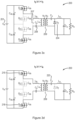
- a two-level zeta asymmetrical half-bridge 100 converts a DC input voltage V in 101 to a DC output voltage V out 102.
- the two-level zeta asymmetrical half-bridge 100 operates by switching MOSFETs Q 1 115 and Q 2 116 to alternate the tank voltage V x 107 between either zero or the input voltage V in .
- the transformer 109 is configured as either a step up or step down transformer, depending on the turns ratio between the primary and secondary windings of the transformer 109.
- the input side of the transformer 109 is an asymmetrical half-bridge and the output is the same as that of a zeta converter.
- This design is known as a two-level zeta asymmetrical half bridge 100, as the circuit is designed to alternate the tank voltage V x 107 between two voltage levels, zero or the input voltage V in 101.
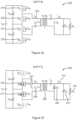
- a three-level zeta asymmetrical half-bridge 200 converts an input voltage V in to an output voltage V out 202.
- Figure 2 shows the input voltage split equally into a first input 203 and a second input 228, each of half the input voltage V in /2. While in this example, both inputs 203, 228 are equal to half the input voltage V in /2, it will be appreciated that each input 203, 228 is not required to be the same value, i.e. the input voltage V in could be split unequally. However, splitting the voltage equally helps to balance the voltage stress over each of the first and second pairs of switching elements and may help to ensure a constant current is applied to the load.
- the three-level zeta asymmetric half-bridge 200 has a resonant tank 211.
- the resonant tank comprises a resonant inductance, which is the leakage inductance of the transformer L lk 219 a primary resonant capacitance C p 208; and a magnetising inductance L m 210 of the transformer 209.
- the voltage applied to the resonant tank 211 is the tank voltage V x 207. In operation, this tank voltage is a square wave that varies between a high voltage and a low voltage at a fixed frequency.
- the role of the resonant tank 211 is to filter out the DC component of the tank voltage V x 207, outputting only the AC square waveform of the tank voltage V x 207 to the input of the transformer 209.
- Using a resonant tank helps to enable the circuit to operate using soft switching, i.e. zero-voltage and/or zero-current switching.
- the transformer 209 has a turns ratio N1:N2 between the primary, input, winding and secondary, output, winding.
- the output of the transformer 209 is the input of a zeta converter 227.
- the zeta converter 227 has a secondary resonant capacitance C s 220; a diode D 2 204; an inductor L o 212 and a capacitor C o 213.
- the zeta converter 227 converts the AC output of the transformer 209 into a DC voltage V out 202.
- the output V out 202 of the zeta converter 227 is applied to a load R o 214.
- Using a zeta converter helps to simplify the control of the circuit, due to a linear static gain and tank to output voltage gain.
- Various examples of zeta converters may be used with this disclosure.
- the three-level zeta asymmetrical half-bridge 200 has an asymmetrical half-bridge 229 made up of a plurality of switching elements Q 1 215, Q 2 216, Q 3 217 and Q 4 218.
- each switching element 215, 216, 217, 218 is a MOSFET with an integrated body diode and a parasitic drain source capacitance C ds .
- any switching elements using actively controlled power semiconductor technology may be used.
- any of IGBTs, HEMTs or bidirectional switches may be used as alternatives, or in combination with MOSFETs. This arrangement helps to enable soft switching to be used in the switch on operations of the switching elements.
- the first input voltage 203 is split across a first pair of switching elements Q 1 215 and Q 2 216.
- the second input voltage 228 is split across a second pair of switching elements Q 3 217 and Q 4 218.
- Each pair has a first switching element, Q 1 215 and Q 4 218 respectively, and a second switching element, Q 2 215 and Q 3 216 respectively.
- the tank voltage V x 207 is the sum of the voltage across the second switching element of the pair, Q 2 215 and Q 3 216, of each pair of switching elements, Q 1 215 and Q 2 216, and Q 3 217 and Q 4 218.
- the asymmetrical half-bridge 229 operates by switching the switching elements Q 1 215, Q 2 216, Q 3 , 217 and Q 4 218 in any one of three predetermined sequences, each corresponding to one of three modes of operation.
- the tank voltage V x 207 is a square wave switching at a fixed frequency between a high voltage and a low voltage.
- fixed frequency pulse width modulation is preferably used. While the voltage switching frequency is fixed, the duty cycle may be varied and this enables the circuit to convert a wide range of input voltages to a specific output voltage.
- the three-level zeta asymmetrical half-bridge 200 has an advantage over a traditional LLC resonant converter which has to operate with high frequency variation over a wide input voltage range. Fixed frequency operation significantly simplifies the EMI filtering required at the input to the three-level zeta asymmetrical half-bridge 200.
- the tank voltage V x 207 alternates between zero and half the input voltage V in /2.
- the tank voltage V x 207 alternates between half the input voltage V in /2 and the input voltage V in .
- the tank voltage V x 207 alternates between zero and the input voltage V in .
- this circuit is known as a three-level zeta asymmetrical half-bridge due to the three possible voltage levels of the tank voltage V x 207.
- Mode 1, mode 2 and mode 3 operation of the three-level zeta asymmetrical half-bridge 200 will be outlined below with reference to additional figures.
- Mode 3 operation of the three-level zeta asymmetrical half-bridge 200 is analogous with operation of the two-level zeta asymmetrical half-bridge 100 and will be described first.
- Various benefits of the three-level zeta asymmetrical half-bridge 200 over the two-level zeta asymmetrical half-bridge 100, even in mode 3 operation, will be discussed.
- Modes 1 and 2 of operation of the three-level zeta asymmetrical half-bridge 200 are novel over the two-level zeta asymmetrical half bridge 100 and have additional advantages over it, which will also be discussed in more detail.
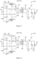
- FIG. 3a to 3f a mode of operation of the three-level zeta asymmetrical half-bridge 200 of Figure 2 is shown.
- the shaded elements in Figures 3a to 3f indicate no conduction.
- the mode of operation outlined in Figures 3a to 3f and Figure 4 is referred to as mode 3.
- the input voltage V in 201 is split evenly between a first capacitor 206 and a second capacitor 230.
- the voltage of the capacitors 206, 230 corresponds to the input voltages V in /2 203, 228 of Figure 2 .
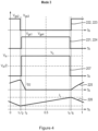
- waveforms are shown between to and T s for mode 3 operation, as described in Figures 3a to 3f , of the three-level zeta asymmetrical half-bridge 200 of Figure 2 .
- the waveforms shown represent the gate-source voltage 222 of the switching element Q 2 216; the gate-source voltage 221 of the switching element Q 1 215; the tank voltage V x 207; the current 225 through the diode D 2 204; and the current 226 through the inductor L o 212.
- the current 226 is filtered by the capacitor C o 213 such that, ideally, a constant current is provided to the load R o .
- the gate-source voltage 222 of the switching element Q 2 216 is the same as the gate-source voltage 223 of the switching element Q 3 217.
- the gate-source voltage 221 of the switching element Q 1 215 is the same as the gate-source voltage 224 of the switching element Q 4 218.
- the tank voltage V x 207 is equal to zero.
- V cp the voltage across the primary resonant capacitance C p 208, is applied to the primary winding of the transformer 209.
- the current 225 through the diode D 2 204 increases as the inductor L o 212 and the capacitor C o 213 supply energy to the load R o 214. This time interval ends when the switching elements Q 2 216 and Q 3 217 are switched off at time t 1 .
- the resonant current through the transformer L lk 219 starts to charge the drain source capacitances of the switching elements Q 2 216 and Q 3 217 to half the input voltage V in /2; and discharge the drain source capacitances of the switching elements Q 1 215 and Q 4 218 to zero.
- the voltages 221, 224 over the switching elements Q 1 215 and Q 4 218 reach zero, and their body diodes will start conducting, thus clamping the switching elements Q 2 216 and Q 3 217 at half the input voltage V in /2.
- the switching elements Q 1 215 and Q 4 218 are switched on.
- zero voltage switching As there is no voltage 221, 224 across the switching elements Q 1 215 or Q 4 218 when they are switched on, this is a first example of zero voltage switching, which is used several times in the operation of the three-level zeta asymmetrical half-bridge 200.
- zero voltage switching includes that it minimises any voltage or power loss over the switching elements of the circuit and minimises the EMI effects of switching. Further benefits include minimising the temperature increase corresponding to power loss in the switching elements, thereby reducing the cooling requirements of the circuit and prolonging the life of the device.
- the tank voltage V x 207 is equal to the input voltage V in 201.
- the voltage applied to the primary winding of the transformer 209 is the tank voltage V x 207 minus the voltage V cp , the voltage across the primary resonant capacitance C p 208.
- the current 225 through the diode D 2 204 starts to decrease.
- the current 225 through the diode D 2 204 is zero and so the diode D 2 204 is blocked.
- Dead-time may be defined as the sufficient time to guarantee safe switching in a power converter.
- the resonant current through the transformer L lk 219 starts to charge the drain source capacitances of the switching elements Q 1 215 and Q 4 218 to half the input voltage V in /2; and discharge the drain source capacitances of the switching elements Q 2 216 and Q 3 217 to zero.
- the voltages 222, 223 over the switching elements Q 2 216 and Q 3 217 will reach zero, and their body diodes will start conducting, thus clamping the switching elements Q 1 215 and Q 4 218 at half the input voltage V in /2.
- the switching elements Q 2 216 and Q 3 217 switch on, again using zero voltage switching.
- the tank voltage V x 207 is equal to zero.
- the voltage V cp the voltage across the primary resonant capacitance C p 208, is applied to the primary winding of the transformer 209.
- the current 225 through the diode D 2 204 increases as the inductor L o 212 and the capacitor C o 213 supply energy to the load R o 214.
- the circuit state is equal to the interval from to to t 1 .
- mode 3 operation of the three-level zeta asymmetric half-bridge 200 is analogous with operation of the two-level zeta half-bridge 100.
- the switching elements Q 1 215 and Q 4 218 of the three-level zeta asymmetric half-bridge 200 operate analogously to the switching element Q 1 115 of the two-level zeta asymmetric half-bridge 100; and the switching elements Q 2 216 and Q 3 217 of the three-level zeta asymmetric half-bridge 200 operate analogously to the switching element Q 2 116 of the two-level zeta asymmetric half-bridge 100.
- the three-level zeta asymmetrical half-bridge 200 at the same voltage switching frequency may be able to use smaller passive components and may have reduced voltage stress over the semiconductors. This may result in improvements in power density and specific power, despite the increased number of active components required.
- the voltages across the switching elements Q 1 to Q 4 215, 216, 217, 218 in the three-level zeta asymmetrical half-bridge 200 is half the voltage across the switching elements Q 1 115 and Q 2 116 in the corresponding two-level zeta asymmetrical half bridge 100. This also reduces in a reduction of the associated cooling requirements.
- the three-level zeta asymmetrical half-bridge 200 offers two additional modes of operation, modes 1 and 2.
- the MOSFETs Q 1 215 and Q 2 216 are operated as a pair and the MOSFETs Q 3 217 and Q 4 218 operate as a pair.
- the first pair of MOSFETs 215 and 216 operates out of phase with the second pair of MOSFETs 217 and 218, which results in the tank voltage V x 207 switching at twice the switching frequency of the MOSFETs 215, 216, 217, 218. Therefore, in modes 1 and 2 operation, half the amplitude of variation of the tank voltage V x 207 results in the same power transfer as an equivalent two-level zeta asymmetrical half-bridge 100. In mode 1 operation, the voltage varies between zero and half the input voltage V in /2; while in mode 2 operation the voltage varies between half the input voltage V in /2 and the input voltage V in .
- a three-level zeta asymmetrical half-bridge 200 in modes 1 and 2 of operation may have beneficial transformer 209 properties.
- the three-level zeta asymmetrical half-bridge 200 is used in step-down applications, compared with an equivalent two-level zeta-asymmetrical half-bridge 100 it may be able to use a smaller transformer 209, with half the turns ratio,.
- a transformer 209 with the same turns ratio may be used, and in this case the three-level zeta asymmetrical half-bridge 200 in modes 1 and 2 of operation will only need to operate the switching elements Q 1 215, Q 2 216, Q 3 , and Q 4 at half the switching frequency. This may lead to a significant reduction in switching losses.
- a compromise between the benefits in transformer 209 size and switching frequency may be determined during the circuit design. Modes 1 and 2 will be described in more detail with reference to additional figures below. Various of these benefits also apply to step-up applications and one to one DC to DC conversion.
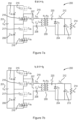
- FIG. 5a to 5k a mode of operation of the three-level zeta asymmetrical half-bridge 200 of Figure 2 is shown.
- the shaded elements in Figures 5a to 5k indicate no conduction.
- the mode of operation outlined in Figures 5a to 5k and Figure 6 is referred to as mode 1.
- the input voltage V in 201 is split evenly between a first capacitor 206 and a second capacitor 230.
- the voltage of the capacitors 206, 230 corresponds to the input voltages V in /2 203, 228 of Figure 2 .
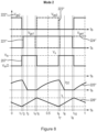
- waveforms are shown between times to and T s for mode 1 operation, as described in Figures 5a to 5k , of the three-level zeta asymmetrical half-bridge 200 of Figure 2 .
- the waveforms shown represent the gate-source voltage 221' of the switching element Q 1 215; the gate-source voltage 222' of the switching element Q 2 216; the gate-source voltage 223' of the switching element Q 3 217; the gate-source voltage 224' of the switching element Q 4 218; the tank voltage V x 207'; the current 225' through the diode D 2 204; and the current 226' through the inductor L o 212.
- the current 226" is filtered by the capacitor C o 213 such that, ideally, a constant current is provided to the load R o .
- the tank voltage V x 207' is equal to half the input voltage V in /2.
- the tank voltage V x 207' minus V cp the voltage across the primary resonant capacitance C p 208, is applied to the primary winding of the transformer 209.
- the output is charged by the secondary winding of the transformer 209 and the secondary resonant capacitance C s .
- the switching element Q 4 218 is turned off, thus starting the dead-time period to ensure zero voltage switching operation.
- the resonant current though the transformer L lk 219 starts to charge the drain source capacitance of the switching element Q 4 218 towards half the input voltage V in /2; and discharge the drain source capacitance of the switching element Q 3 217 to zero.
- the voltage 223' over the switching element Q 3 217 will reach zero, and its body diode will start conducting, thus clamping the switching element Q 4 218 at half the input voltage V in /2.
- the switching element Q 3 217 switches on, again using zero voltage switching.
- the tank voltage V x 207' is equal to zero.
- the voltage applied to the primary winding of the transformer is the tank voltage V x 207' minus V cp , the voltage across the primary resonant capacitance C p 208.
- the current 225' through the diode D 2 204 increases as the inductor L o 212 and the capacitor C o 213 supply energy to the load R o 214. This time interval ends when the switching element Q 2 216 is switched off at time t 3 .
- the resonant current though the transformer L lk 219 starts to charge the drain source capacitance of the switching element Q 2 216 towards half the input voltage V in /2; and discharge the drain source capacitance of the switching element Q 1 215 to zero.
- the voltage 221' over the switching element Q 1 215 will reach zero and its body diode will start conducting, thus clamping the switching element Q 2 216 at half the input voltage V in /2.
- the switching element Q 1 switches on, using zero voltage switching.
- the tank voltage V x 207' is equal to half the input voltage V in /2.
- the voltage applied to the primary winding of the transformer 209 is the tank voltage V x 207' minus the voltage V cp , the voltage across the primary resonant capacitance C p 208.
- the current 225' through D 2 204 starts to decrease.
- the current 225" through the diode D 2 204 is zero and so the diode D 2 204 is blocked.
- the resonant current though the transformer L lk 219 starts to charge the drain source capacitance of the switching element Q 1 215 towards half the input voltage V in /2; and discharge the drain source capacitance of the switching element Q 2 216 to zero.
- the voltage 222' over the switching element Q 2 216 will reach zero, and its body diode will start conducting, thus clamping the switching element Q 1 215 at half the input voltage V in /2.
- the switching element Q 2 216 switches on using zero voltage switching.
- the circuit state at time t 6 shown in Figure 5g is approximately equivalent to the circuit state at time t 1 as shown in Figure 5a .
- the key difference is that the first pair of switching elements Q 1 215 and Q 2 at time t 6 are now in a state equivalent to the second pair of switching elements Q 3 and Q 4 at time t 1 and vice-versa.
- Figures 5h to 5k are hence analogous to Figures 5b to 5e and therefore will not be discussed in detail.
- the tank voltage V x 207' in Figure 6 , mode 1 operation can be seen to be switching at twice the frequency as the tank voltage V x 207 in Figure 4 , mode 3 operation, and with half the amplitude. This is as a result of the first pair of switching elements Q 1 215 and Q 2 216 operating out of phase with the second pair of switching elements Q 3 217 and Q 4 218.
- the tank voltage V x 207' in mode 1 operation alternates between zero and half the input voltage V in /2, rather than alternating between zero and the input voltage V in as per mode 1. If the input voltage were, however, to be split unequally between each pair of switches, the tank voltage V x 207' would instead alternate in a sequence between zero, the first voltage 203, zero and the second voltage 228.
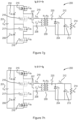
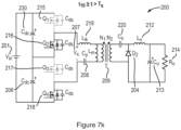
- FIG. 7a to 7k a mode of operation of the three-level zeta asymmetrical half-bridge 200 of Figure 2 is shown.
- the shaded elements in Figures 7a to 7k indicate no conduction.
- the mode of operation outlined in Figures 7a to 7k and Figure 8 is referred to as mode 2.
- the input voltage V in 201 is split evenly between a first capacitor 206 and a second capacitor 230.
- the voltage of the capacitors 206, 230 corresponds to the input voltages V in /2 203, 228 of Figure 2 .
- waveforms are shown between times to and T s for mode 2 operation, as described in Figures 7a to 7k , of the three-level zeta asymmetrical half-bridge 200 of Figure 2 .
- the waveforms shown represent the gate-source voltage 221" of the switching element Q 1 215; the gate-source voltage 222" of the switching element Q 2 216; the gate-source voltage 223" of the switching element Q 3 217; the gate-source voltage 224" of the switching element Q 4 218; the tank voltage V x 207"; the current 225" through the diode D 2 204; and the current 226" through the inductor L o 212.
- the current 226" is filtered by the capacitor C o 213 such that, ideally, a constant current is provided to the load R o .
- the tank voltage V x 207" is equal to half the input voltage V in /2.
- the voltage applied to the primary winding of the transformer is the tank voltage V x 207" minus V cp , the voltage across the primary resonant capacitance C p 208.
- the current 225" through the diode D 2 204 increases as the inductor L o 212 and the capacitor C o 213 supply energy to the load R o 214. This time interval ends when the switching element Q 2 216 is switched off at time t 1 .
- the resonant current though the transformer L lk 219 starts to charge the drain source capacitance of the switching element Q 2 216 towards half the input voltage V in /2; and discharge the drain source capacitance of the switching element Q 1 215 to zero.
- the voltage 221" over the switching element Q 1 215 will reach zero and its body diode will start conducting, thus clamping Q 2 216 at half the input voltage V in /2.
- the switching element Q 1 switches on, using zero voltage switching.
- the tank voltage V x 207" is equal to the input voltage V in .
- the voltage applied to the primary winding of the transformer 209 is the tank voltage V x 207" minus the voltage V cp , the voltage across the primary resonant capacitance C p 208.
- the current 225" through the diode D 2 204 starts to decrease.
- the current 225" through the diode D 2 204 is zero and so the diode D 2 204 is blocked.
- the resonant current though the transformer L lk 219 starts to charge the drain source capacitance of the switching element Q 4 218 towards half the input voltage V in /2; and discharge the drain source capacitance of Q 3 217 to zero.
- the voltage 223" over the switching element Q 3 217 will reach zero, and its body diode will start conducting, thus clamping the switching element Q 4 218 at half the input voltage V in /2.
- the switching element Q 3 217 switches on using zero voltage switching.
- the tank voltage V x 207" is equal to half the input voltage V in /2.
- the voltage applied to the primary winding of the transformer is the tank voltage V x 207" minus V cp , the voltage across the primary resonant capacitance C p 208.
- the current 225" through the diode D 2 204 increases as the inductor L o 212 and the capacitor C o 213 supply energy to the load R o 214. This time interval ends when the switching element Q 3 217 is switched off at time t 6 .
- the resonant current though the transformer L lk 219 starts to charge the drain source capacitance of the switching element Q 3 217 towards half the input voltage V in /2; and discharge the drain source capacitance of the switching element Q 4 215 to zero.
- the voltage 221" over the switching element Q 4 218 will reach zero and its body diode will start conducting, thus clamping the switching element Q 3 217 at half the input voltage V in /2.
- the switching element Q 4 switches on, using zero voltage switching.
- the circuit state at time t 6 shown in Figure 7g is approximately equivalent to the circuit state at time t 1 as shown in Figure 7a .
- the key difference is that the first pair of switching elements Q 1 215 and Q 2 at time t 6 are now in a state equivalent to the second pair of switching elements Q 3 and Q 4 at time t 1 and vice-versa.
- Figures 7h to 7k are hence analogous to Figures 7b to 7e and therefore will not be discussed in detail.
- Mode 2 operation is similar to mode 1 operation, however the tank voltage V x 207" in Figure 8 , mode 2 operation, can be seen to be switching between half the input voltage V in /2 and the input voltage V in , rather than between zero and half the input voltage V in /2.
- the phase shift between the first pair of switching elements, Q 1 215 and Q 2 216, and the second pair of switching elements, Q 3 217 and Q 4 218, is different from the phase shift in mode 1 operation.
- the tank voltage V x 207" in mode 2 operation alternates between half the input voltage V in /2 and the input voltage V in in this example. However, if the input voltage were split unequally between each pair of switches, the tank voltage V x 207" would instead alternate in a sequence between the first voltage 203, the input voltage V in , the second voltage 228, and the input voltage V in .
- tank to output voltage gain and duty cycle 901 is shown for a two-level zeta asymmetrical half-bridge 100 or a three-level zeta asymmetrical half-bridge 200, this relationship is the same for both circuits. Also shown is the relationship between tank to output voltage gain and duty cycle 902 for a traditional asymmetrical half-bridge.
- FIG. 9b the relationship between static gain and duty cycle 905 is shown for a three-level asymmetrical half-bridge 200 in mode 2 operation, which is a linear relationship as the duty cycle is varied between 0 and 0.5. Also shown is the relationship between static gain and duty cycle 904 for a three-level asymmetrical half-bridge 200 in mode 1, which is a linear relationship as the duty cycle is varied between 0.5 and 1. Also shown is the relationship between static gain and duty cycle 903 for a three-level asymmetrical half-bridge 200 in mode 3 operation, which is the same as for a two-level asymmetrical half-bridge 100, this is a linear relationship as the duty cycle is varied between 0 and 1.
- the static gain 903 of a three-level zeta asymmetrical half bridge 200 in mode 3 operation, or a two-level zeta asymmetrical half-bridge 100 is higher than the static gain 905 of a three-level zeta asymmetrical half bridge 200 in mode 2 operation.
- the static gain 903 of a three-level zeta-asymmetrical half bridge in mode 3 operation, or a two-level zeta asymmetrical half-bridge 100 is the same as the static gain 904 of a three-level zeta asymmetrical half bridge 200 in mode 1 operation; hence 903 overlaps with 904 along the length of 904 in Fig. 9b .
- the relationship between static gain and duty cycle 906 is shown for a traditional asymmetrical half-bridge.
- both the two-level zeta asymmetrical half-bridge 100 and the three-level zeta asymmetrical half-bridge 200 have a linear relationship between duty cycle and tank to output voltage gain 901; and a linear relationship between duty cycle and static gain 903, 904, 905.
- the tank to output voltage gain 902 and the static gain 906 of a traditional asymmetrical half-bridge operating at the same switching frequency has a non-linear, quadratic, relationship with duty cycle.
- This provides various benefits in the control of a zeta asymmetrical half-bridge over a traditional asymmetrical half-bridge, as the linear relationship is much simpler to account for than the non-linear relationship.
- Figure 9b shows that the static gain 903, 904, 905 of a three-level zeta asymmetrical half-bridge 200 is different depending on which of the 3 modes of operation that the device operates in. This provides greater flexibility in the configuration of the device when compared with a two-level zeta asymmetrical half-bridge 100.
- Figure 9b shows that for a given 1:1 transformer, and a given switching frequency of the switching elements, modes 1 and 2 will have a linear gain 904, 905 between zero and 0.5. This may be lower than the gain 903 during mode 3 operation, which is the same as the gain 903 of an equivalent two-level zeta asymmetrical half-bridge 100, which is between zero and 1.
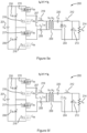
- a variant 300 of the three-level zeta asymmetrical half-bridge 200 of Figure 2 is shown, wherein the diode D 2 204 is replaced with a rectifying switching element Q 5 304, which in this example is a MOSFET, for active rectification; as opposed to the passive rectification used in the three-level zeta asymmetrical half bridge 200.
- a rectifying switching element Q 5 304 which in this example is a MOSFET, for active rectification
- This is an example of a variation of the zeta converter 227 used in the three-level zeta asymmetrical half-bridge 200 of Figure 2 .
- Active rectification has lower conduction losses than passive rectification, this is particularly useful for applications with a high current load, which often correspond with low voltage applications.
- the zeta converter 327 comprises: a MOSFET Q 5 304 in series with the secondary winding of the transformer 309; an output inductor L o 312 in series with a secondary resonant capacitance C s 320, and in parallel with MOSFET Q 5 304.
- the zeta converter 327 further comprises an output capacitor C O 313 in series with the output inductor L O 312.
- the DC output voltage V out 314 is applied to a load R O 314 in parallel with the output capacitor C O 313 and in series with the output inductor L O 312.
- FIG. 10b another variant 400 of the three-level zeta asymmetrical half-bridge 200 of Figure 2 is shown with a tapped transformer 409.
- This is another example of a variation of the zeta converter 227 used in the three-level zeta asymmetrical half-bridge 200 of Figure 2 .
- a Tapped transformer gives an extra degree of freedom to optimize the secondary side conduction of the secondary resonant capacitance C s 420 and the diode D 2 404 towards loss and/or size reduction. This is achieved by varying the ratio of turns between each of the output windings of the tapped transformer 409.
- the zeta (427) converter comprises: a rectifying diode D 2 404 in series with the secondary winding of the tapped transformer 409; an output inductor L o 412 connected part-way along the secondary winding of the transformer 409; and an output capacitor C O 413 in series with the output inductor L O 412.
- the DC output voltage V out 414 is applied to a load R O 414 in parallel with the output capacitor C O 413 and in series with the output inductor L O 412.
- the zeta converter 427 further comprises a secondary resonant capacitance C S 420 in series with each of the secondary winding of the transformer 409, the rectifying diode D 2 404, and the output inductor L O 412.
- a further variant 500 of the three-level zeta asymmetrical half-bridge 200 of Figure 2 which has both a rectifying switching element Q 5 504, which in this example is a MOSFET, for active rectification, and a tapped transformer 509.
- This is a further example of a variation of the zeta converter 227 used in the three-level zeta asymmetrical half-bridge 200 of Figure 2 and has the advantages of both the active rectification and trapped transformed topologies.
- the zeta converter 527 comprises: a MOSFET Q 5 504 in series with the secondary winding of the tapped transformer 509; an output inductor L O 512 connected part-way along the secondary winding of the transformer 509; an output capacitor C O 513 in series with the output inductor L O 512.
- the DC output voltage V out 514 is applied to a load R O 514 in parallel with the output capacitor C O 513 and in series with the output inductor L O 512.
- the zeta converter 527 further comprises a secondary resonant capacitance C S 520 in series with each of the secondary winding of the transformer 509, the MOSFET Q 5 504, and the output inductor L O 512.
- the three-level zeta asymmetrical half-bridge 200; 300; 400; 500 may be useful for step down DC voltage conversion applications due to the benefits listed above, for example the reduction in the size of the transformer and/or the reduction in switching frequency relative to an equivalent two-level zeta-asymmetrical half-bridge.
- the three-level zeta asymmetrical half-bridge 200; 300; 400; 500 is useful in stepping down voltages in the region of 400V to 3kV to a voltage of approximately 28V. Therefore, a three-level zeta asymmetrical half-bridge 200; 300; 400; 500 would be particularly useful in aircrafts where DC power distribution is used.
- the high voltages may be used in the aircraft's propulsion systems, while the lower voltages may be used elsewhere in the aircraft. Galvanic isolation between the high voltage load is particularly important to ensure proper grounding protection and safety.
- the three-level zeta asymmetrical half-bridge 200; 300; 400; 500 may also be useful when the high input voltage has a wide variation, for example a variation between 400v to 750V, as the three-level zeta asymmetrical half-bridge 200; 300; 400; 500 will be able to operate at a fixed switching frequency, despite the high voltage variation by changing the duty cycle. This presents an advantage over a traditional LLC converter for this application which would require a high variation of switching frequency.
Landscapes
- Engineering & Computer Science (AREA)
- Power Engineering (AREA)
- Dc-Dc Converters (AREA)
Abstract
Description
- This disclosure relates to multilevel series resonant DC to DC voltage converters, in particular to a three-level zeta asymmetrical half-bridge.
- In various DC to DC voltage applications, it may be important to isolate the high voltage part of the circuit from the low voltage part of the circuit. In addition, there are often large variations in either the input or output voltage. Various topologies of existing DC to DC voltage converters require a high degree of complexity of control of the circuit and/or have complex input EMI filtering requirements. Furthermore, reducing the voltage stresses across components may allow smaller components to be used in many applications. It is an aim to reduce losses in DC to DC power conversion, to reduce cooling requirements of the circuit, and/or to prolong the lifetime of circuit components.
- When viewed from a first aspect, the present disclosure provides a three-level zeta asymmetrical half-bridge for converting a DC input voltage into a DC output voltage comprising: an asymmetrical half-bridge, comprising a first pair of switching elements, and a second pair of switching elements in series with the first pair of switching elements; wherein a first portion of the DC input voltage is applied in parallel with the first pair of switching elements, and a second portion of the DC input voltage is applied in parallel with the second pair of switching elements; a resonant tank in parallel with one switching element from each pair of switching elements, the resonant tank comprising a magnetising inductance of a primary winding of a transformer, a resonant inductance and a primary resonant capacitance; and a zeta converter connected to a secondary winding of the transformer; wherein each pair of switching elements is arranged to operate in a sequence to selectively connect and disconnect the resonant tank to the respective first or second portion of the DC input voltage, such that a voltage of the resonant tank alternates between a low voltage and a high voltage; and wherein the resonant tank is arranged to filter out a DC component of the voltage of the resonant tank and output a filtered resonant tank voltage to the primary winding of the transformer; and wherein the zeta converter is arranged to rectify the output of the secondary winding of the transformer to output the DC output voltage.
- A two-level half-bridge may be defined as a circuit in which two switches are connected in series with a power supply. Alternately switching on one switch and off the other switch applies the power supply voltage across the open, i.e. off, switch. Switching on and off each switch alternately applies the power supply voltage across each switch. An asymmetrical half-bridge may be defined as two switches connected in series with a power supply, wherein the load on each switch, i.e. in parallel with each switch, is not equal, i.e. not symmetric.
- A three-level asymmetrical half bridge may be defined as two two-level asymmetrical half-bridges in series with each other, wherein a load is applied across the outputs of one of the two switches of each two-level asymmetrical half-bridge. By applying either no voltage across the load, the voltage of one of the two power supplies, or the voltage of both power supplies, the voltage across the load may be varied between three voltage levels.
- A resonant tank may be defined as a circuit made up of at least one inductor, and at least one capacitor, that resonates at a specific frequency, called the resonant frequency.
- A zeta converter may be defined as an DC-DC voltage converter. A traditional zeta converter has an input voltage applied across an inductor, wherein the inductor is in series with a capacitor, and wherein the output of the capacitor is in series with two parallel branches. The first branch comprises a diode arranged to only allow the flow of current toward the capacitor, and the second branch comprising an inductor and a second capacitor in series. A load is applied across, i.e. in parallel, with the second capacitor.
- Use of a transformer in the three-level zeta asymmetrical half-bridge provides galvanic isolation between the input and output of the circuit.
- A three-level zeta asymmetrical half-bridge may be defined as a three-level asymmetrical half bridge which outputs to a resonant tank, comprising the first winding of a transformer, wherein the second winding of the transformer is the input to a zeta converter, and wherein the zeta converter outputs an output voltage to a load. The three-level zeta asymmetrical half-bridge comprises each of the asymmetrical half-bridge, the resonant tank, the transformer, and the zeta converter.
- In some examples, the switching elements comprise a switch, a (e.g. parasitic) diode and a (e.g. parasitic) capacitance in parallel; and optionally wherein the switching elements are each arranged to switch on when the voltage across the respective switching element is zero.
- In some examples, the first pair of switching elements and the second pair of switching elements are arranged to operate in phase, to alternate the voltage applied to the resonant tank between the DC input voltage and ground.
- In phase may be defined as each pair of switching elements applying a high voltage and a low voltage to the resonant tank at the same times, by switching the first switching element (e.g. main switching element) from each pair of switching elements on at the same time, and off at the same time. In phase may also be defined as switching the second switching element (e.g. complementary switching element) from each pair of switching elements on at the same time and off at the same time.
- In some examples, the first portion and the second portion of the DC input voltage is equal to half the DC input voltage. In various examples, this may enable the converter to apply a constant, rather than variable, output voltage to the load.
- In some examples, the DC input voltage is split across a first capacitor, across which the first portion of the DC input voltage is applied, and a second capacitor, across which the second portion of the DC input voltage is applied; wherein the first capacitor is in series with the second capacitor.
- In some examples, the first pair of switching elements and the second pair of switching elements are arranged to operate out of phase.
- Out of phase may be defined as the timing of switching of the first switching element from each pair of switching elements being different, i.e. they do not both switch on at the same time, or off at the same time, but one may switch on at the same time that the other switches off. The same is true for the second switching elements from each pair of switching elements.
- In some examples, the first pair of switching elements and the second pair of switching elements are arranged to operate out of phase to alternate the voltage applied to the resonant tank between half the DC input voltage and ground.
- In some examples, the first pair of switching elements and the second pair of switching elements are arranged to operate out of phase to alternate the voltage applied to the resonant tank between the DC input voltage and half the DC input voltage.
- In some examples, the zeta converter comprises: a secondary resonant capacitance in series with the secondary winding of the transformer; a rectifying diode in series with the secondary winding of the transformer; an output inductor in series with the secondary resonant capacitance and in parallel with the rectifying diode; an output capacitor in series with the output inductor; and wherein the DC output voltage is applied to a load in parallel with the output capacitor and in series with the output inductor.
- In some examples, the zeta converter comprises: a rectifying switching element comprising a switch and a diode in parallel, wherein the rectifying switching element is in series with the secondary winding of the transformer; an output inductor in series with the secondary resonant capacitance and in parallel with the rectifying switching element; an output capacitor in series with the output inductor; and wherein the DC output voltage is applied to a load in parallel with the output capacitor and in series with the output inductor.
- In some examples, the rectifying switching element is a MOSFET with an integrated (e.g. parasitic) body diode and switch.
- In some examples, the transformer is a tapped transformer; and wherein the zeta converter comprises: a rectifying diode in series with the secondary winding of the transformer; an output inductor connected part-way along the secondary winding of the transformer; an output capacitor in series with the output inductor; wherein the DC output voltage is applied to a load in parallel with the output capacitor and in series with the output inductor; and wherein the zeta converter further comprises a secondary resonant capacitance in series with each of the secondary winding of the transformer, the rectifying diode, and the output inductor.
- A tapped transformer may be defined as a transformer wherein the secondary winding of the transformer has an additional output part-way along the length of the secondary transformer winding.
- In some examples, the transformer is a centre tapped transformer, i.e. the transformer is tapped at the centre.
- In some examples, the transformer is a tapped transformer; and wherein the zeta converter comprises: a rectifying switching element comprising a switch and a diode in parallel, wherein the active rectifying switching element is in series with the secondary winding of the transformer; an output inductor connected part-way along the secondary winding of the transformer; an output capacitor in series with the output inductor; wherein the DC output voltage is applied to a load in parallel with the output capacitor and in series with the output inductor; and wherein the zeta converter further comprises a secondary resonant capacitance in series with each of the secondary winding of the transformer, the rectifying switching element, and the output inductor.
- In various examples, any switching elements using actively controlled power semiconductor technology may be used. In various examples, instead of MOSFETs any of IGBTs, HEMTs or bidirectional switches are used as alternatives, or in combination with MOSFETs. In some examples, the rectifying switching element is a MOSFET with an integrated body diode and switch.
- In some examples, the transformer is a step-down transformer. In some examples, the transformer is a step-up transformer. In some examples, the transformer is a one to one transformer.
- In some examples, the primary resonant inductance is the leakage inductance of the primary winding of the transformer.
- In some examples, the switching elements are arranged to alternate the voltage of the resonant tank between the low voltage and the high voltage at a fixed frequency.
- In some examples, a proportion of time that the voltage applied to the resonant tank is a high voltage may be varied.
- In some examples, the switching elements are arranged to operate to generate a square wave to the resonant tank such that the voltage of the resonant tank is a square wave.
- When viewed from a second aspect, the present disclosure provides a method of operating a three-level zeta asymmetrical half-bridge (e.g. according to any of the examples herein) to convert a DC input voltage into a DC output voltage, wherein the three-level zeta asymmetrical half-bridge comprises:
- an asymmetrical half-bridge, comprising a first pair of switching elements, and a second pair of switching elements in series with the first pair of switching elements;
- a resonant tank in parallel with one switching element from each pair of switching elements, the resonant tank comprising a magnetising inductance of a primary winding of a transformer, a resonant inductance and a primary resonant capacitance; and
- a zeta converter connected to a secondary winding of the transformer;
- applying a first portion of the DC input voltage in parallel with the first pair of switching elements;
- applying a second portion of the DC input voltage in parallel with the second pair of switching elements;
- operating each pair of switching elements in a sequence to selectively connect and disconnect the resonant tank to the respective first or second portion of the DC input voltage, such that a voltage of the resonant tank alternates between a low voltage and a high voltage;
- the resonant tank filtering out a DC component of the voltage of the resonant tank and outputting a filtered resonant tank voltage to the primary winding of the transformer; and
- the zeta converter rectifying the output of the secondary winding of the transformer to output the DC output voltage.
- In some examples, the method further comprises switching the switching elements on when the voltage across the respective switching element is zero.
- In some examples, the method further comprises operating first pair of switching elements and the second pair of switching elements in phase to alternate the voltage applied to the resonant tank between the DC input voltage and ground.
- In some examples, the method further comprises splitting the DC input voltage across a first capacitor, across which the first portion of the DC input voltage is applied, and a second capacitor, across which the second portion of the DC input voltage is applied.
- In some examples, the method further comprises operating the first pair of switching elements and the second pair of switching elements out of phase to alternate the voltage applied to the resonant tank between half the DC input voltage and ground.
- In some examples, the method further comprises operating the first pair of switching elements and the second pair of switching elements out of phase to alternate the voltage applied to the resonant tank between the DC input voltage and half the DC input voltage.
- In some examples, the method further comprises operating the switching elements to alternate the voltage of the resonant tank between the low voltage and the high voltage at a fixed frequency.
- In some examples, the method further comprises operating the switching elements to alternate the voltage of the resonant tank between the low voltage and the high voltage, and a proportion of time that the voltage applied to the resonant tank is a high voltage may be varied.
- In some examples, the method further comprises operating the switching elements to generate a square wave to the resonant tank, such that the voltage of the resonant tank is a square wave.
- One or more non-limiting examples will now be described, by way of example only, and with reference to the accompanying figures in which:
-
Figure 1 shows a two-level zeta asymmetrical half-bridge; -
Figure 2 shows a three-level zeta asymmetrical half-bridge according to the present disclosure; -
Figures 3a to 3f show different operating states of the three-level zeta asymmetrical half-bridge ofFigure 2 duringmode 3 operation; -
Figure 4 shows waveforms of voltages and currents during themode 3 operation ofFigures 3a to 3f ; -
Figures 5a to 5k show different operating states of the three-level zeta asymmetrical half-bridge ofFigure 2 duringmode 1 operation; -
Figure 6 shows waveforms of voltages and currents during themode 1 operation ofFigures 5a to 5k ; -
Figures 7a to 7k show different operating states of the three-level zeta asymmetrical half-bridge ofFigure 2 duringmode 2 operation; -
Figure 8 shows waveforms of voltages and currents during themode 2 operation ofFigures 7a to 7k ; -
Figure 9a shows the relationship between duty cycle and tank voltage to output voltage gain for each of a traditional asymmetrical half-bridge, a two-level zeta asymmetrical half-bridge and a three-level zeta asymmetrical half-bridge, each using a 1:1 transformer and operating at a given switching frequency of the switching elements; -
Figure 9b shows the relationship between duty cycle and static gain for each of a traditional asymmetrical half-bridge, a two-level zeta asymmetrical half-bridge and a three-level zeta asymmetrical half-bridge, each using a 1:1 transformer and operating at a given switching frequency of the switching elements; -
Figure 10a shows a three-level zeta asymmetrical half-bridge according to the present disclosure, with active rectification; -
Figure 10b shows a three-level zeta asymmetrical half-bridge according to the present disclosure, with a tapped-transformer; and -
Figure 10c shows a three-level zeta asymmetrical half-bridge according to the present disclosure, with active rectification and a tapped transformer. - Referring to
Figure 1 , a two-level zeta asymmetrical half-bridge 100 converts a DCinput voltage V in 101 to a DCoutput voltage V out 102. - The two-level zeta asymmetrical half-
bridge 100 operates by switchingMOSFETs Q 1 115 andQ 2 116 to alternate thetank voltage V x 107 between either zero or the input voltage Vin. - The
transformer 109 is configured as either a step up or step down transformer, depending on the turns ratio between the primary and secondary windings of thetransformer 109. - The input side of the
transformer 109 is an asymmetrical half-bridge and the output is the same as that of a zeta converter. This design is known as a two-level zetaasymmetrical half bridge 100, as the circuit is designed to alternate thetank voltage V x 107 between two voltage levels, zero or theinput voltage V in 101. - Referring to
Figure 2 , a three-level zeta asymmetrical half-bridge 200, according to the present disclosure converts an input voltage Vin to anoutput voltage V out 202.
Figure 2 shows the input voltage split equally into afirst input 203 and asecond input 228, each of half the input voltage Vin/2. While in this example, bothinputs input - The three-level zeta asymmetric half-
bridge 200 has aresonant tank 211. The resonant tank comprises a resonant inductance, which is the leakage inductance of the transformer Llk 219 a primaryresonant capacitance C p 208; and amagnetising inductance L m 210 of thetransformer 209. The voltage applied to theresonant tank 211 is thetank voltage V x 207. In operation, this tank voltage is a square wave that varies between a high voltage and a low voltage at a fixed frequency. The role of theresonant tank 211 is to filter out the DC component of thetank voltage V x 207, outputting only the AC square waveform of thetank voltage V x 207 to the input of thetransformer 209. Using a resonant tank helps to enable the circuit to operate using soft switching, i.e. zero-voltage and/or zero-current switching. - The
transformer 209 has a turns ratio N1:N2 between the primary, input, winding and secondary, output, winding. - The output of the
transformer 209 is the input of azeta converter 227. Thezeta converter 227 has a secondaryresonant capacitance C s 220; adiode D 2 204; aninductor L o 212 and acapacitor C o 213. Thezeta converter 227 converts the AC output of thetransformer 209 into aDC voltage V out 202. Theoutput V out 202 of thezeta converter 227 is applied to aload R o 214. Using a zeta converter helps to simplify the control of the circuit, due to a linear static gain and tank to output voltage gain. Various examples of zeta converters may be used with this disclosure. - The three-level zeta asymmetrical half-
bridge 200 has an asymmetrical half-bridge 229 made up of a plurality of switchingelements Q 1 215,Q 2 216,Q 3 217 andQ 4 218. In this example, each switchingelement - In this example, the
first input voltage 203 is split across a first pair of switchingelements Q 1 215 andQ 2 216. Thesecond input voltage 228 is split across a second pair of switchingelements Q 3 217 andQ 4 218. Each pair has a first switching element,Q 1 215 andQ 4 218 respectively, and a second switching element,Q 2 215 andQ 3 216 respectively. Thetank voltage V x 207 is the sum of the voltage across the second switching element of the pair,Q 2 215 andQ 3 216, of each pair of switching elements,Q 1 215 andQ 2 216, andQ 3 217 andQ 4 218. - The asymmetrical half-
bridge 229 operates by switching theswitching elements Q 1 215,Q 2 216, Q3, 217 andQ 4 218 in any one of three predetermined sequences, each corresponding to one of three modes of operation. In each mode of operation, thetank voltage V x 207 is a square wave switching at a fixed frequency between a high voltage and a low voltage. Hence, in this example, fixed frequency pulse width modulation is preferably used. While the voltage switching frequency is fixed, the duty cycle may be varied and this enables the circuit to convert a wide range of input voltages to a specific output voltage. Therefore, the three-level zeta asymmetrical half-bridge 200 has an advantage over a traditional LLC resonant converter which has to operate with high frequency variation over a wide input voltage range. Fixed frequency operation significantly simplifies the EMI filtering required at the input to the three-level zeta asymmetrical half-bridge 200. - In
mode 1 operation, thetank voltage V x 207 alternates between zero and half the input voltage Vin/2. Inmode 2 operation, thetank voltage V x 207 alternates between half the input voltage Vin/2 and the input voltage Vin. Inmode 3 operation, thetank voltage V x 207 alternates between zero and the input voltage Vin. Hence, this circuit is known as a three-level zeta asymmetrical half-bridge due to the three possible voltage levels of thetank voltage V x 207. -
Mode 1,mode 2 andmode 3 operation of the three-level zeta asymmetrical half-bridge 200 will be outlined below with reference to additional figures.Mode 3 operation of the three-level zeta asymmetrical half-bridge 200 is analogous with operation of the two-level zeta asymmetrical half-bridge 100 and will be described first. Various benefits of the three-level zeta asymmetrical half-bridge 200 over the two-level zeta asymmetrical half-bridge 100, even inmode 3 operation, will be discussed. -
Modes bridge 200 are novel over the two-level zetaasymmetrical half bridge 100 and have additional advantages over it, which will also be discussed in more detail. - Referring to
Figures 3a to 3f andFigure 4 , a mode of operation of the three-level zeta asymmetrical half-bridge 200 ofFigure 2 is shown. The shaded elements inFigures 3a to 3f indicate no conduction. The mode of operation outlined inFigures 3a to 3f andFigure 4 is referred to asmode 3. InFigure 3a to 3f , theinput voltage V in 201 is split evenly between afirst capacitor 206 and asecond capacitor 230. The voltage of thecapacitors Figure 2 . - Referring to
Figure 4 , waveforms are shown between to and Ts formode 3 operation, as described inFigures 3a to 3f , of the three-level zeta asymmetrical half-bridge 200 ofFigure 2 . The waveforms shown represent the gate-source voltage 222 of the switchingelement Q 2 216; the gate-source voltage 221 of the switchingelement Q 1 215; thetank voltage V x 207; the current 225 through thediode D 2 204; and the current 226 through theinductor L o 212. The current 226 is filtered by thecapacitor C o 213 such that, ideally, a constant current is provided to the load Ro. - In
mode 3 operation, the gate-source voltage 222 of the switchingelement Q 2 216 is the same as the gate-source voltage 223 of the switchingelement Q 3 217. Inmode 3 operation, the gate-source voltage 221 of the switchingelement Q 1 215 is the same as the gate-source voltage 224 of the switchingelement Q 4 218. - Between times to and t1, as shown in
Figure 3a andFigure 4 , thetank voltage V x 207 is equal to zero. Vcp, the voltage across the primaryresonant capacitance C p 208, is applied to the primary winding of thetransformer 209. The current 225 through thediode D 2 204 increases as theinductor L o 212 and thecapacitor C o 213 supply energy to theload R o 214. This time interval ends when theswitching elements Q 2 216 andQ 3 217 are switched off at time t1. - Between times t1 and t2, as shown in
Figure 3b andFigure 4 , the resonant current through thetransformer L lk 219 starts to charge the drain source capacitances of theswitching elements Q 2 216 andQ 3 217 to half the input voltage Vin/2; and discharge the drain source capacitances of theswitching elements Q 1 215 andQ 4 218 to zero. Before time t2, thevoltages elements Q 1 215 andQ 4 218 reach zero, and their body diodes will start conducting, thus clamping theswitching elements Q 2 216 andQ 3 217 at half the input voltage Vin/2. At time t2 theswitching elements Q 1 215 andQ 4 218 are switched on. - As there is no
voltage switching elements Q 1 215 orQ 4 218 when they are switched on, this is a first example of zero voltage switching, which is used several times in the operation of the three-level zeta asymmetrical half-bridge 200. There are various benefits of zero voltage switching, including that it minimises any voltage or power loss over the switching elements of the circuit and minimises the EMI effects of switching. Further benefits include minimising the temperature increase corresponding to power loss in the switching elements, thereby reducing the cooling requirements of the circuit and prolonging the life of the device. - Between times t2 and t3, as shown in
Figure 3c andFigure 4 , thetank voltage V x 207 is equal to theinput voltage V in 201. The voltage applied to the primary winding of thetransformer 209 is thetank voltage V x 207 minus the voltage Vcp, the voltage across the primaryresonant capacitance C p 208. The current 225 through thediode D 2 204 starts to decrease. At time t3, the current 225 through thediode D 2 204 is zero and so thediode D 2 204 is blocked. - Between times t3 and t4, as shown in
Figure 3d andFigure 4 , the output is still charged by the secondary winding of thetransformer 209 and the secondaryresonant capacitance C s 220. At time t4, theswitching elements Q 1 215 andQ 4 218 are turned off, thus starting the dead-time period to ensure zero voltage switching operation. Dead-time may be defined as the sufficient time to guarantee safe switching in a power converter. - Between times t4 and t5, as shown in
Figure 3e andFigure 4 , the resonant current through thetransformer L lk 219 starts to charge the drain source capacitances of theswitching elements Q 1 215 andQ 4 218 to half the input voltage Vin/2; and discharge the drain source capacitances of theswitching elements Q 2 216 andQ 3 217 to zero. Before time t5, thevoltages elements Q 2 216 andQ 3 217 will reach zero, and their body diodes will start conducting, thus clamping theswitching elements Q 1 215 andQ 4 218 at half the input voltage Vin/2. At t5 theswitching elements Q 2 216 andQ 3 217 switch on, again using zero voltage switching. - Between times t5 and Ts, as shown in
Figure 3f andFig 4 , thetank voltage V x 207 is equal to zero. The voltage Vcp, the voltage across the primaryresonant capacitance C p 208, is applied to the primary winding of thetransformer 209. The current 225 through thediode D 2 204 increases as theinductor L o 212 and thecapacitor C o 213 supply energy to theload R o 214. At this point, the circuit state is equal to the interval from to to t1. - Referring to
Figure 1, Figure 2 ,Figures 3a to 3f , andFigure 4 ;mode 3 operation of the three-level zeta asymmetric half-bridge 200 is analogous with operation of the two-level zeta half-bridge 100. Theswitching elements Q 1 215 andQ 4 218 of the three-level zeta asymmetric half-bridge 200 operate analogously to theswitching element Q 1 115 of the two-level zeta asymmetric half-bridge 100; and theswitching elements Q 2 216 andQ 3 217 of the three-level zeta asymmetric half-bridge 200 operate analogously to theswitching element Q 2 116 of the two-level zeta asymmetric half-bridge 100. - However, as the
input voltage 201 to the three-level zeta asymmetric half-bridge 200 is split, when compared with an equivalent two-level zeta asymmetrical half-bridge 100 the three-level zeta asymmetrical half-bridge 200 at the same voltage switching frequency may be able to use smaller passive components and may have reduced voltage stress over the semiconductors. This may result in improvements in power density and specific power, despite the increased number of active components required. In other words, the voltages across the switching elements Q1 toQ bridge 200 is half the voltage across theswitching elements Q 1 115 andQ 2 116 in the corresponding two-level zetaasymmetrical half bridge 100. This also reduces in a reduction of the associated cooling requirements. - In addition, the three-level zeta asymmetrical half-
bridge 200 offers two additional modes of operation,modes MOSFETs Q 1 215 andQ 2 216 are operated as a pair and theMOSFETs Q 3 217 andQ 4 218 operate as a pair. The first pair ofMOSFETs MOSFETs tank voltage V x 207 switching at twice the switching frequency of theMOSFETs modes tank voltage V x 207 results in the same power transfer as an equivalent two-level zeta asymmetrical half-bridge 100. Inmode 1 operation, the voltage varies between zero and half the input voltage Vin/2; while inmode 2 operation the voltage varies between half the input voltage Vin/2 and the input voltage Vin. - As a result of the reduction in the amplitude of the variation of the
tank voltage V x 207; when compared with an equivalent two-level zeta asymmetric half-bridge 100, a three-level zeta asymmetrical half-bridge 200 inmodes beneficial transformer 209 properties. For example when the three-level zeta asymmetrical half-bridge 200 is used in step-down applications, compared with an equivalent two-level zeta-asymmetrical half-bridge 100 it may be able to use asmaller transformer 209, with half the turns ratio,. - Alternatively, a
transformer 209 with the same turns ratio may be used, and in this case the three-level zeta asymmetrical half-bridge 200 inmodes switching elements Q 1 215,Q 2 216, Q3, and Q4 at half the switching frequency. This may lead to a significant reduction in switching losses. A compromise between the benefits intransformer 209 size and switching frequency may be determined during the circuit design.Modes - Referring to
Figures 5a to 5k andFigure 6 , a mode of operation of the three-level zeta asymmetrical half-bridge 200 ofFigure 2 is shown. The shaded elements inFigures 5a to 5k indicate no conduction. The mode of operation outlined inFigures 5a to 5k andFigure 6 is referred to asmode 1. InFigure 5a to 5k , theinput voltage V in 201 is split evenly between afirst capacitor 206 and asecond capacitor 230. The voltage of thecapacitors Figure 2 . - Referring to
Figure 6 , waveforms are shown between times to and Ts formode 1 operation, as described inFigures 5a to 5k , of the three-level zeta asymmetrical half-bridge 200 ofFigure 2 . The waveforms shown represent the gate-source voltage 221' of the switchingelement Q 1 215; the gate-source voltage 222' of the switchingelement Q 2 216; the gate-source voltage 223' of the switchingelement Q 3 217; the gate-source voltage 224' of the switchingelement Q 4 218; the tank voltage Vx 207'; the current 225' through thediode D 2 204; and the current 226' through theinductor L o 212. The current 226" is filtered by thecapacitor C o 213 such that, ideally, a constant current is provided to the load Ro. - Between times to and t1, as shown in
Figure 5a andFigure 6 , the tank voltage Vx 207' is equal to half the input voltage Vin/2. The tank voltage Vx 207' minus Vcp, the voltage across the primaryresonant capacitance C p 208, is applied to the primary winding of thetransformer 209. The output is charged by the secondary winding of thetransformer 209 and the secondary resonant capacitance Cs. At time t1, the switchingelement Q 4 218 is turned off, thus starting the dead-time period to ensure zero voltage switching operation. - Between times t1 and t2, as shown in
Figure 5b andFigure 6 , the resonant current though thetransformer L lk 219 starts to charge the drain source capacitance of the switchingelement Q 4 218 towards half the input voltage Vin/2; and discharge the drain source capacitance of the switchingelement Q 3 217 to zero. Before time t2, the voltage 223' over the switchingelement Q 3 217 will reach zero, and its body diode will start conducting, thus clamping the switchingelement Q 4 218 at half the input voltage Vin/2. At time t2 the switchingelement Q 3 217 switches on, again using zero voltage switching. - Between times t2 and t3, as shown in
Figure 5c andFigure 6 , the tank voltage Vx 207' is equal to zero. The voltage applied to the primary winding of the transformer is the tank voltage Vx 207' minus Vcp, the voltage across the primaryresonant capacitance C p 208. The current 225' through thediode D 2 204 increases as theinductor L o 212 and thecapacitor C o 213 supply energy to theload R o 214. This time interval ends when the switchingelement Q 2 216 is switched off at time t3. - Between times t3 and t4, as shown in
Figure 5d andFigure 6 , the resonant current though thetransformer L lk 219 starts to charge the drain source capacitance of the switchingelement Q 2 216 towards half the input voltage Vin/2; and discharge the drain source capacitance of the switchingelement Q 1 215 to zero. Before time t4, the voltage 221' over the switchingelement Q 1 215 will reach zero and its body diode will start conducting, thus clamping the switchingelement Q 2 216 at half the input voltage Vin/2. At time t4, the switching element Q1 switches on, using zero voltage switching. - Between times t4 and t5, as shown in
Figure 5e andFigure 6 , the tank voltage Vx 207' is equal to half the input voltage Vin/2. The voltage applied to the primary winding of thetransformer 209 is the tank voltage Vx 207' minus the voltage Vcp, the voltage across the primaryresonant capacitance C p 208. The current 225' throughD 2 204 starts to decrease. At time t5, the current 225" through thediode D 2 204 is zero and so thediode D 2 204 is blocked. - Between times t5 and t6, as shown in
Figure 5f andFigure 6 , the output is still charged by the secondary winding of thetransformer 209 and the secondaryresonant capacitance C s 220. At time t6, the switchingelement Q 1 215 is turned off, thus starting the dead-time period to ensure zero voltage switching operation. - Between times t6 and t7, as shown in
Figure 5g andFigure 6 , the resonant current though thetransformer L lk 219 starts to charge the drain source capacitance of the switchingelement Q 1 215 towards half the input voltage Vin/2; and discharge the drain source capacitance of the switchingelement Q 2 216 to zero. Before time t7, the voltage 222' over the switchingelement Q 2 216 will reach zero, and its body diode will start conducting, thus clamping the switchingelement Q 1 215 at half the input voltage Vin/2. At time t7 the switchingelement Q 2 216 switches on using zero voltage switching. - The circuit state at time t6 shown in
Figure 5g is approximately equivalent to the circuit state at time t1 as shown inFigure 5a . The key difference is that the first pair of switchingelements Q 1 215 and Q2 at time t6 are now in a state equivalent to the second pair of switching elements Q3 and Q4 at time t1 and vice-versa.Figures 5h to 5k are hence analogous toFigures 5b to 5e and therefore will not be discussed in detail. - As explained above, the tank voltage Vx 207' in
Figure 6 ,mode 1 operation, can be seen to be switching at twice the frequency as thetank voltage V x 207 inFigure 4 ,mode 3 operation, and with half the amplitude. This is as a result of the first pair of switchingelements Q 1 215 andQ 2 216 operating out of phase with the second pair of switchingelements Q 3 217 andQ 4 218. The tank voltage Vx 207' inmode 1 operation alternates between zero and half the input voltage Vin/2, rather than alternating between zero and the input voltage Vin as permode 1. If the input voltage were, however, to be split unequally between each pair of switches, the tank voltage Vx 207' would instead alternate in a sequence between zero, thefirst voltage 203, zero and thesecond voltage 228. - Referring to
Figures 7a to 7k andFigure 8 , a mode of operation of the three-level zeta asymmetrical half-bridge 200 ofFigure 2 is shown. The shaded elements inFigures 7a to 7k indicate no conduction. The mode of operation outlined inFigures 7a to 7k andFigure 8 is referred to asmode 2. InFigure 7a to 7k , theinput voltage V in 201 is split evenly between afirst capacitor 206 and asecond capacitor 230. The voltage of thecapacitors Figure 2 . - Referring to
Figure 8 , waveforms are shown between times to and Ts formode 2 operation, as described inFigures 7a to 7k , of the three-level zeta asymmetrical half-bridge 200 ofFigure 2 . The waveforms shown represent the gate-source voltage 221" of the switchingelement Q 1 215; the gate-source voltage 222" of the switchingelement Q 2 216; the gate-source voltage 223" of the switchingelement Q 3 217; the gate-source voltage 224" of the switchingelement Q 4 218; thetank voltage V x 207"; the current 225" through thediode D 2 204; and the current 226" through theinductor L o 212. The current 226" is filtered by thecapacitor C o 213 such that, ideally, a constant current is provided to the load Ro. - Between times to and t1, as shown in
Figure 7a andFigure 8 , thetank voltage V x 207" is equal to half the input voltage Vin/2. The voltage applied to the primary winding of the transformer is thetank voltage V x 207" minus Vcp, the voltage across the primaryresonant capacitance C p 208. The current 225" through thediode D 2 204 increases as theinductor L o 212 and thecapacitor C o 213 supply energy to theload R o 214. This time interval ends when the switchingelement Q 2 216 is switched off at time t1. - Between times t1 and t2, as shown in
Figure 7b andFigure 8 , the resonant current though thetransformer L lk 219 starts to charge the drain source capacitance of the switchingelement Q 2 216 towards half the input voltage Vin/2; and discharge the drain source capacitance of the switchingelement Q 1 215 to zero. Before time t2, thevoltage 221" over the switchingelement Q 1 215 will reach zero and its body diode will start conducting, thus clampingQ 2 216 at half the input voltage Vin/2. At time t2, the switching element Q1 switches on, using zero voltage switching. - Between times t2 and t3, as shown in
Figure 7c andFigure 8 , thetank voltage V x 207" is equal to the input voltage Vin. The voltage applied to the primary winding of thetransformer 209 is thetank voltage V x 207" minus the voltage Vcp, the voltage across the primaryresonant capacitance C p 208. The current 225" through thediode D 2 204 starts to decrease. At time t3, the current 225" through thediode D 2 204 is zero and so thediode D 2 204 is blocked. - Between times t3 and t4, as shown in
Figure 7d andFigure 8 , the output is still charged by the secondary winding of thetransformer 209 and the secondaryresonant capacitance C s 220. At time t4, the switchingelement Q 4 215 is turned off, thus starting the dead-time period to ensure zero voltage switching operation. - Between times t4 and t5, as shown in
Figure 7e andFigure 8 , the resonant current though thetransformer L lk 219 starts to charge the drain source capacitance of the switchingelement Q 4 218 towards half the input voltage Vin/2; and discharge the drain source capacitance ofQ 3 217 to zero. Before time t5, thevoltage 223" over the switchingelement Q 3 217 will reach zero, and its body diode will start conducting, thus clamping the switchingelement Q 4 218 at half the input voltage Vin/2. At time t5 the switchingelement Q 3 217 switches on using zero voltage switching. - Between times t5 and t6, as shown in
Figure 7f andFigure 8 , thetank voltage V x 207" is equal to half the input voltage Vin/2. The voltage applied to the primary winding of the transformer is thetank voltage V x 207" minus Vcp, the voltage across the primaryresonant capacitance C p 208. The current 225" through thediode D 2 204 increases as theinductor L o 212 and thecapacitor C o 213 supply energy to theload R o 214. This time interval ends when the switchingelement Q 3 217 is switched off at time t6. - Between times t6 and t7, as shown in
Figure 7g andFigure 8 , the resonant current though thetransformer L lk 219 starts to charge the drain source capacitance of the switchingelement Q 3 217 towards half the input voltage Vin/2; and discharge the drain source capacitance of the switchingelement Q 4 215 to zero. Before time t7, thevoltage 221" over the switchingelement Q 4 218 will reach zero and its body diode will start conducting, thus clamping the switchingelement Q 3 217 at half the input voltage Vin/2. At time t7, the switching element Q4 switches on, using zero voltage switching. - The circuit state at time t6 shown in
Figure 7g is approximately equivalent to the circuit state at time t1 as shown inFigure 7a . The key difference is that the first pair of switchingelements Q 1 215 and Q2 at time t6 are now in a state equivalent to the second pair of switching elements Q3 and Q4 at time t1 and vice-versa.Figures 7h to 7k are hence analogous toFigures 7b to 7e and therefore will not be discussed in detail. -
Mode 2 operation is similar tomode 1 operation, however thetank voltage V x 207" inFigure 8 ,mode 2 operation, can be seen to be switching between half the input voltage Vin/2 and the input voltage Vin, rather than between zero and half the input voltage Vin/2. The phase shift between the first pair of switching elements,Q 1 215 andQ 2 216, and the second pair of switching elements,Q 3 217 andQ 4 218, is different from the phase shift inmode 1 operation. - The best example of this can be seen by comparing
Figures 5c and6 withFigures 7c and8 . At time t2, approximately zero voltage is applied to theresonant tank 211 duringmode 1 operation inFigures 5c and6 . This is because theswitching elements Q 2 216 andQ 3 217 are on at the same time. This respectively clamps theswitching elements Q 1 215 andQ 4 218 to half the input voltage Vin/2 and therefore no voltage is applied to theresonant tank 211. The inverse happens at time t2 inFigures 7c and8 , resulting in the input voltage Vin being applied to theresonant tank 211. Due to the respective phase shifts, theswitching elements Q 1 215 andQ 4 218 will never be on at the same time duringmode 1 operation, and theswitching elements Q 2 216 andQ 3 217 will never be on at the same time duringmode 2 operation. - The
tank voltage V x 207" inmode 2 operation alternates between half the input voltage Vin/2 and the input voltage Vin in this example. However, if the input voltage were split unequally between each pair of switches, thetank voltage V x 207" would instead alternate in a sequence between thefirst voltage 203, the input voltage Vin, thesecond voltage 228, and the input voltage Vin. - Referring to
Fig. 9a , the relationship between tank to output voltage gain andduty cycle 901 is shown for a two-level zeta asymmetrical half-bridge 100 or a three-level zeta asymmetrical half-bridge 200, this relationship is the same for both circuits. Also shown is the relationship between tank to output voltage gain andduty cycle 902 for a traditional asymmetrical half-bridge. - Referring to
Fig. 9b , the relationship between static gain andduty cycle 905 is shown for a three-level asymmetrical half-bridge 200 inmode 2 operation, which is a linear relationship as the duty cycle is varied between 0 and 0.5. Also shown is the relationship between static gain andduty cycle 904 for a three-level asymmetrical half-bridge 200 inmode 1, which is a linear relationship as the duty cycle is varied between 0.5 and 1. Also shown is the relationship between static gain andduty cycle 903 for a three-level asymmetrical half-bridge 200 inmode 3 operation, which is the same as for a two-level asymmetrical half-bridge 100, this is a linear relationship as the duty cycle is varied between 0 and 1. When the duty cycle is below 0.5, thestatic gain 903 of a three-level zetaasymmetrical half bridge 200 inmode 3 operation, or a two-level zeta asymmetrical half-bridge 100, is higher than thestatic gain 905 of a three-level zetaasymmetrical half bridge 200 inmode 2 operation. When the duty cycle is above 0.5, thestatic gain 903 of a three-level zeta-asymmetrical half bridge inmode 3 operation, or a two-level zeta asymmetrical half-bridge 100, is the same as thestatic gain 904 of a three-level zetaasymmetrical half bridge 200 inmode 1 operation; hence 903 overlaps with 904 along the length of 904 inFig. 9b . Finally, the relationship between static gain andduty cycle 906 is shown for a traditional asymmetrical half-bridge. - Referring to
Figures 9a and 9b , it can be seen that both the two-level zeta asymmetrical half-bridge 100 and the three-level zeta asymmetrical half-bridge 200 have a linear relationship between duty cycle and tank tooutput voltage gain 901; and a linear relationship between duty cycle andstatic gain output voltage gain 902 and thestatic gain 906 of a traditional asymmetrical half-bridge operating at the same switching frequency has a non-linear, quadratic, relationship with duty cycle. This provides various benefits in the control of a zeta asymmetrical half-bridge over a traditional asymmetrical half-bridge, as the linear relationship is much simpler to account for than the non-linear relationship. - Additionally,
Figure 9b shows that thestatic gain bridge 200 is different depending on which of the 3 modes of operation that the device operates in. This provides greater flexibility in the configuration of the device when compared with a two-level zeta asymmetrical half-bridge 100. -
Figure 9b shows that for a given 1:1 transformer, and a given switching frequency of the switching elements,modes linear gain gain 903 duringmode 3 operation, which is the same as thegain 903 of an equivalent two-level zeta asymmetrical half-bridge 100, which is between zero and 1. This again highlights the advantage that operation of a three-level zeta asymmetrical half-bridge 200 inmodes bridge 100, and/or may operate with a lower switching frequency, due to the lowerlinear gain - Referring to
Figure 10a , avariant 300 of the three-level zeta asymmetrical half-bridge 200 ofFigure 2 is shown, wherein thediode D 2 204 is replaced with a rectifyingswitching element Q 5 304, which in this example is a MOSFET, for active rectification; as opposed to the passive rectification used in the three-level zetaasymmetrical half bridge 200. This is an example of a variation of thezeta converter 227 used in the three-level zeta asymmetrical half-bridge 200 ofFigure 2 . Active rectification has lower conduction losses than passive rectification, this is particularly useful for applications with a high current load, which often correspond with low voltage applications. - In this example, the
zeta converter 327 comprises: aMOSFET Q 5 304 in series with the secondary winding of thetransformer 309; anoutput inductor L o 312 in series with a secondaryresonant capacitance C s 320, and in parallel withMOSFET Q 5 304. Thezeta converter 327 further comprises anoutput capacitor C O 313 in series with theoutput inductor L O 312. In this example, the DCoutput voltage V out 314 is applied to aload R O 314 in parallel with theoutput capacitor C O 313 and in series with theoutput inductor L O 312. - Referring to
Figure 10b , anothervariant 400 of the three-level zeta asymmetrical half-bridge 200 ofFigure 2 is shown with a tappedtransformer 409. This is another example of a variation of thezeta converter 227 used in the three-level zeta asymmetrical half-bridge 200 ofFigure 2 . A Tapped transformer gives an extra degree of freedom to optimize the secondary side conduction of the secondaryresonant capacitance C s 420 and thediode D 2 404 towards loss and/or size reduction. This is achieved by varying the ratio of turns between each of the output windings of the tappedtransformer 409. - In this example, the zeta (427) converter comprises: a rectifying
diode D 2 404 in series with the secondary winding of the tappedtransformer 409; anoutput inductor L o 412 connected part-way along the secondary winding of thetransformer 409; and anoutput capacitor C O 413 in series with theoutput inductor L O 412. In this example, the DCoutput voltage V out 414 is applied to aload R O 414 in parallel with theoutput capacitor C O 413 and in series with theoutput inductor L O 412. In this example, thezeta converter 427 further comprises a secondaryresonant capacitance C S 420 in series with each of the secondary winding of thetransformer 409, the rectifyingdiode D 2 404, and theoutput inductor L O 412. - Referring to
Figure 10c , afurther variant 500 of the three-level zeta asymmetrical half-bridge 200 ofFigure 2 is shown which has both a rectifyingswitching element Q 5 504, which in this example is a MOSFET, for active rectification, and a tappedtransformer 509. This is a further example of a variation of thezeta converter 227 used in the three-level zeta asymmetrical half-bridge 200 ofFigure 2 and has the advantages of both the active rectification and trapped transformed topologies.
In this example, thezeta converter 527 comprises: aMOSFET Q 5 504 in series with the secondary winding of the tappedtransformer 509; anoutput inductor L O 512 connected part-way along the secondary winding of thetransformer 509; anoutput capacitor C O 513 in series with theoutput inductor L O 512. In this example, the DCoutput voltage V out 514 is applied to aload R O 514 in parallel with theoutput capacitor C O 513 and in series with theoutput inductor L O 512. In this example, thezeta converter 527 further comprises a secondaryresonant capacitance C S 520 in series with each of the secondary winding of thetransformer 509, theMOSFET Q 5 504, and theoutput inductor L O 512. One skilled in the art will appreciate that the three-level zeta asymmetrical half-bridge 200; 300; 400; 500 may be useful for step down DC voltage conversion applications due to the benefits listed above, for example the reduction in the size of the transformer and/or the reduction in switching frequency relative to an equivalent two-level zeta-asymmetrical half-bridge. In addition, by splitting theinput voltage 201 into afirst input voltage 203 and asecond input voltage 228, therefore reducing the size of the voltage applied to the components of the circuit, higher input voltages may be applied to the circuit and/or smaller components may be used. In particular, the three-level zeta asymmetrical half-bridge 200; 300; 400; 500 is useful in stepping down voltages in the region of 400V to 3kV to a voltage of approximately 28V. Therefore, a three-level zeta asymmetrical half-bridge 200; 300; 400; 500 would be particularly useful in aircrafts where DC power distribution is used. Here, the high voltages may be used in the aircraft's propulsion systems, while the lower voltages may be used elsewhere in the aircraft. Galvanic isolation between the high voltage load is particularly important to ensure proper grounding protection and safety. - The three-level zeta asymmetrical half-
bridge 200; 300; 400; 500 may also be useful when the high input voltage has a wide variation, for example a variation between 400v to 750V, as the three-level zeta asymmetrical half-bridge 200; 300; 400; 500 will be able to operate at a fixed switching frequency, despite the high voltage variation by changing the duty cycle. This presents an advantage over a traditional LLC converter for this application which would require a high variation of switching frequency.
Claims (15)
- A three-level zeta asymmetrical half-bridge (200; 300; 400; 500) for converting a DC input voltage (201) into a DC output voltage (202) comprising:an asymmetrical half-bridge (229), comprising a first pair of switching elements (215, 216), and a second pair of switching elements (217, 218) in series with the first pair of switching elements (215, 216);a resonant tank (211) in parallel with one switching element (216, 217) from each pair of switching elements (215, 216, 217, 218), the resonant tank comprising a magnetising inductance (210) of a primary winding of a transformer (209), a resonant inductance (219) and a primary resonant capacitance (208); anda zeta converter (227; 327; 427; 527) connected to a secondary winding of the transformer (209);wherein a first portion (203) of the DC input voltage (201) is applied in parallel with the first pair of switching elements (215, 216), and a second portion (228) of the DC input voltage (201) is applied in parallel with the second pair of switching elements (217, 218);wherein each pair of switching elements (215, 216, 217, 218) is arranged to operate in a sequence to selectively connect and disconnect the resonant tank (211) to the respective first (203) or second (228) portion of the DC input voltage (201), such that a voltage (207) of the resonant tank (211) alternates between a low voltage and a high voltage;wherein the resonant tank (211) is arranged to filter out a DC component of the voltage (207) of the resonant tank (211) and output a filtered resonant tank voltage to the primary winding of the transformer (209); andwherein the zeta converter (227; 327; 427; 527) is arranged to rectify the output of the secondary winding of the transformer (209) to output the DC output voltage (202).
- The three-level zeta asymmetrical half-bridge of claim 1 wherein the switching elements (215, 216, 217, 218) comprise a switch, diode and capacitance in parallel; and optionally wherein
the switching elements (215, 216, 217, 218) are each arranged to switch on when the voltage (221, 222, 223, 224) across the respective switching element (215, 216, 217, 218) is zero. - The three-level zeta asymmetrical half-bridge of any preceding claim wherein the first pair of switching elements (215, 216) and the second pair of switching elements (217, 218) are arranged to operate in phase to alternate the voltage (207) applied to the resonant tank (211) between the DC input voltage (201) and ground.
- The three-level zeta asymmetrical half-bridge of any preceding claim wherein the first pair of switching elements (215, 216) and the second pair of switching elements (217, 218) are arranged to operate out of phase.
- The three-level zeta asymmetrical half-bridge of any preceding claim wherein the first portion (203) and the second portion (228) of the DC input voltage (201) is equal to half the DC input voltage; and optionallywherein the DC input voltage (201) is split across a first capacitor (230), across which the first portion (203) of the DC input voltage (201) is applied, and a second capacitor (206), across which the second portion (228) of the DC input voltage (201) is applied;wherein the first capacitor (230) is in series with the second capacitor (206).
- The three-level zeta asymmetrical half-bridge of claim 4 wherein the first pair of switching elements (215, 216) and the second pair of switching elements (217, 218) are arranged to operate out of phase to alternate the voltage (207) applied to the resonant tank (211) between half the DC input voltage and ground.
- The three-level zeta asymmetrical half-bridge of claim 4 wherein the first pair of switching elements (215, 216) and the second pair of switching elements (217, 218) are arranged to operate out of phase to alternate the voltage (207) applied to the resonant tank (211) between the DC input voltage (201) and half the DC input voltage.
- The three-level zeta asymmetrical half-bridge of any preceding claim wherein the zeta converter (227) comprises:a secondary resonant capacitance (220) in series with the secondary winding of the transformer (209);a rectifying diode (204) in series with the secondary winding of the transformer (209);an output inductor (212) in series with the secondary resonant capacitance (220) and in parallel with the rectifying diode (204);an output capacitor (213) in series with the output inductor (212); andwherein the DC output voltage (202) is applied to a load (214) in parallel with the output capacitor (213) and in series with the output inductor (212).
- The three-level zeta asymmetrical half-bridge of any of claims 1 to 7 wherein the zeta converter (327) comprises:a rectifying switching element (304) comprising a switch and a diode in parallel, wherein the rectifying switching element (304) is in series with the secondary winding of the transformer (309);an output inductor (312) in series with the secondary resonant capacitance (320) and in parallel with the rectifying switching element (304);an output capacitor (313) in series with the output inductor (312); andwherein the DC output voltage is applied to a load (314) in parallel with the output capacitor (313) and in series with the output inductor (312); andoptionally wherein the rectifying switching element (304) is a MOSFET with an integrated body diode and switch.
- The three-level zeta asymmetrical half-bridge of any of claims 1 to 7 wherein:the transformer is a tapped transformer (409); andwherein the zeta (427) converter comprises:a rectifying diode (404) in series with the secondary winding of the transformer (409);an output inductor (412) connected part-way along the secondary winding of the transformer (409);an output capacitor (413) in series with the output inductor (412);wherein the DC output voltage is applied to a load (414) in parallel with the output capacitor (413) and in series with the output inductor (412); andwherein the zeta converter (427) further comprises a secondary resonant capacitance (420) in series with each of the secondary winding of the transformer (409), the rectifying diode (404), and the output inductor (412).
- The three-level zeta asymmetrical half-bridge of any of claims 1 to 7 wherein:the transformer is a tapped transformer (509); andwherein the zeta converter (527) comprises:a rectifying switching element (504) comprising a switch and a diode in parallel, wherein the active rectifying switching element (504) is in series with the secondary winding of the transformer (509);an output inductor (512) connected part-way along the secondary winding of the transformer (509);an output capacitor (513) in series with the output inductor (512);wherein the DC output voltage is applied to a load (514) in parallel with the output capacitor (513) and in series with the output inductor (512); andwherein the zeta converter (527) further comprises a secondary resonant capacitance (520) in series with each of the secondary winding of the transformer (509), the rectifying switching element (504), and the output inductor (512); andoptionally wherein the rectifying switching element (504) is a MOSFET with an integrated body diode and switch.
- The three-level zeta asymmetrical half-bridge of any preceding claim wherein the primary resonant inductance (219) is the leakage inductance of the primary winding of the transformer (209; 409; 509).
- The three-level zeta asymmetrical half-bridge of any preceding claim wherein the switching elements (215, 216, 217, 218) are arranged to alternate the voltage (207) of the resonant tank (211) between the low voltage and the high voltage at a fixed frequency; and optionally
wherein a proportion of time that the voltage (207) applied to the resonant tank (211) is a high voltage is varied. - The three-level zeta asymmetrical half-bridge according to any preceding claim wherein the switching elements (215, 216, 217, 218) are arranged to operate to generate a square wave to the resonant tank (211) such that the voltage (207) of the resonant tank (211) is a square wave.
- A method of operating a three-level zeta asymmetrical half-bridge (200; 300; 400; 500) to convert a DC input voltage (201) into a DC output voltage (202), wherein the three-level zeta asymmetrical half-bridge (200; 300; 400; 500) comprises:an asymmetrical half-bridge (229), comprising a first pair of switching elements (215, 216), and a second pair of switching elements (217, 218) in series with the first pair of switching elements (215, 216);a resonant tank (211) in parallel with one switching element (216, 217) from each pair of switching elements (215, 216, 217, 218), the resonant tank comprising a magnetising inductance (2109) of a primary winding of a transformer (209), a resonant inductance (219) and a primary resonant capacitance (208); anda zeta converter (227; 327; 427; 527) connected to a secondary winding of the transformer (209);the method comprising:applying a first portion (203) of the DC input voltage (201) in parallel with the first pair of switching elements (215, 216);applying a second portion (228) of the DC input voltage (201) in parallel with the second pair of switching elements (217, 218);operating each pair of switching elements (215, 216, 217, 218) in a sequence to selectively connect and disconnect the resonant tank (211) to the respective first (203) or second (228) portion of the DC input voltage (201), such that a voltage (207) of the resonant tank (211) alternates between a low voltage and a high voltage;the resonant tank (211) filtering out a DC component of the voltage (207) of the resonant tank (211) and outputting a filtered resonant tank voltage to the primary winding of the transformer (209); andthe zeta converter (227; 327; 427; 527) rectifying the output of the secondary winding of the transformer (209) to output the DC output voltage (202).
Priority Applications (2)
| Application Number | Priority Date | Filing Date | Title |
|---|---|---|---|
| EP23156581.3A EP4418518A1 (en) | 2023-02-14 | 2023-02-14 | Three-level zeta asymmetrical half-bridge |
| US18/394,286 US20240275291A1 (en) | 2023-02-14 | 2023-12-22 | Three-level zeta asymmetrical half-bridge |
Applications Claiming Priority (1)
| Application Number | Priority Date | Filing Date | Title |
|---|---|---|---|
| EP23156581.3A EP4418518A1 (en) | 2023-02-14 | 2023-02-14 | Three-level zeta asymmetrical half-bridge |
Publications (1)
| Publication Number | Publication Date |
|---|---|
| EP4418518A1 true EP4418518A1 (en) | 2024-08-21 |
Family
ID=85238993
Family Applications (1)
| Application Number | Title | Priority Date | Filing Date |
|---|---|---|---|
| EP23156581.3A Pending EP4418518A1 (en) | 2023-02-14 | 2023-02-14 | Three-level zeta asymmetrical half-bridge |
Country Status (2)
| Country | Link |
|---|---|
| US (1) | US20240275291A1 (en) |
| EP (1) | EP4418518A1 (en) |
Citations (4)
| Publication number | Priority date | Publication date | Assignee | Title |
|---|---|---|---|---|
| US20160211759A1 (en) * | 2013-09-25 | 2016-07-21 | Osram Gmbh | Electronic resonant and insulated half-bridge zeta converter |
| US20210067045A1 (en) * | 2019-08-26 | 2021-03-04 | Delta Electronics, Inc. | Three-level modulation for wide output voltage range isolated dc/dc converters |
| EP3916984A1 (en) * | 2020-05-25 | 2021-12-01 | Delta Electronics, Inc. | Isolated dc/dc converters for wide output voltage range and control methods thereof |
| US20220021295A1 (en) * | 2020-07-17 | 2022-01-20 | Goodrich Corporation | Low weight isolated integrated single-stage ac-dc led driver |
Family Cites Families (1)
| Publication number | Priority date | Publication date | Assignee | Title |
|---|---|---|---|---|
| US6282109B1 (en) * | 2000-04-28 | 2001-08-28 | Simon Fraidlin | Controller for a non-isolated power factor corrector and method of regulating the power factor corrector |
-
2023
- 2023-02-14 EP EP23156581.3A patent/EP4418518A1/en active Pending
- 2023-12-22 US US18/394,286 patent/US20240275291A1/en active Pending
Patent Citations (4)
| Publication number | Priority date | Publication date | Assignee | Title |
|---|---|---|---|---|
| US20160211759A1 (en) * | 2013-09-25 | 2016-07-21 | Osram Gmbh | Electronic resonant and insulated half-bridge zeta converter |
| US20210067045A1 (en) * | 2019-08-26 | 2021-03-04 | Delta Electronics, Inc. | Three-level modulation for wide output voltage range isolated dc/dc converters |
| EP3916984A1 (en) * | 2020-05-25 | 2021-12-01 | Delta Electronics, Inc. | Isolated dc/dc converters for wide output voltage range and control methods thereof |
| US20220021295A1 (en) * | 2020-07-17 | 2022-01-20 | Goodrich Corporation | Low weight isolated integrated single-stage ac-dc led driver |
Non-Patent Citations (5)
| Title |
|---|
| BOR-REN LIN ET AL: "Soft-Switching Zeta-Flyback Converter With a Buck-Boost Type of Active Clamp", IEEE TRANSACTIONS ON INDUSTRIAL ELECTRONICS, IEEE SERVICE CENTER, PISCATAWAY, NJ, USA, vol. 54, no. 5, 1 October 2007 (2007-10-01), pages 2813 - 2822, XP011191140, ISSN: 0278-0046, DOI: 10.1109/TIE.2007.901366 * |
| LIU DONG ET AL: "Zero-Voltage Switching PWM Strategy Based Capacitor Current-Balancing Control for Half-Bridge Three-Level DC/DC Converter", IEEE TRANSACTIONS ON POWER ELECTRONICS, INSTITUTE OF ELECTRICAL AND ELECTRONICS ENGINEERS, USA, vol. 33, no. 1, 1 January 2018 (2018-01-01), pages 357 - 369, XP011662022, ISSN: 0885-8993, [retrieved on 20171006], DOI: 10.1109/TPEL.2017.2659648 * |
| MASAHITO SHOYAMA ET AL: "ZERO-VOLTAGE-SWITCHED PUSH-PULL DC-DC CONVERTER", PROCEEDINGS OF THE ANNUAL POWER ELECTRONICS SPECIALISTS CONFERENCE. MASSACHUSETTS, 25 - 27 JUNE, 1991; [PROCEEDINGS OF THE ANNUAL POWER ELECTRONICS SPECIALISTS CONFERENCE], NEW YORK, IEEE, US, vol. CONF. 22, 23 June 1991 (1991-06-23), pages 223 - 229, XP000278405, ISBN: 978-0-7803-0090-3 * |
| MURTHY-BELLUR D ET AL: "Two-transistor Zeta-flyback DC-DC converter with reduced transistor voltage stress", ELECTRONIC LETTERS, THE INSTITUTION OF ENGINEERING AND TECHNOLOGY, vol. 46, no. 10, 13 May 2010 (2010-05-13), pages 719 - 720, XP006035579, ISSN: 1350-911X, DOI: 10.1049/EL:20103494 * |
| YAN ZHU ET AL: "Three-level switching cell for low voltage/high-current DC-DC converters", EIGHTEENTH ANNUAL IEEE APPLIED POWER ELECTRONICS CONFERENCE AND EXPOSITION, 2003. APEC '03; [ANNUAL APPLIED POWER ELECTRONICS CONFERENCE], NEW YORK, NY : IEEE, US, 9 February 2003 (2003-02-09), pages 121 - 125vol.1, XP032155889, ISBN: 978-0-7803-7768-4, DOI: 10.1109/APEC.2003.1179202 * |
Also Published As
| Publication number | Publication date |
|---|---|
| US20240275291A1 (en) | 2024-08-15 |
Similar Documents
| Publication | Publication Date | Title |
|---|---|---|
| US8891261B2 (en) | Three-phase three-level soft-switched PFC rectifiers | |
| US6344979B1 (en) | LLC series resonant DC-to-DC converter | |
| US7869237B1 (en) | Phase-shifted bridge with auxiliary circuit to maintain zero-voltage-switching | |
| US20020034083A1 (en) | Zero voltage switching DC-DC converter | |
| KR20140047523A (en) | Bi-directional dc/dc converter | |
| US11296607B2 (en) | DC-DC converter | |
| Tuan et al. | Output Power Characteristics of Unidirectional Secondary-Resonant Single-Active-Bridge DC-DC Converter using Pulse Width Control | |
| Nguyen et al. | Current-fed Quasi-Z-source full-bridge isolated DC–DC converter | |
| US6999325B2 (en) | Current/voltage converter arrangement | |
| US5870291A (en) | Asymmetrical half-bridge converter having adjustable parasitic resistances to offset output voltage DC bias | |
| US12301125B2 (en) | Power converter topology | |
| CN114930703B (en) | DC power converter | |
| KR101377124B1 (en) | An isolated single switch resonant converter and an isolated interleaving single switch resonant converter using the same | |
| Rehlaender et al. | Dual interleaved 3.6 kW LLC converter operating in half-bridge, full-bridge and phase-shift mode as a single-stage architecture of an automotive on-board DC-DC converter | |
| KR100874809B1 (en) | Three-Level DC-DC Converter Using Zero-Voltage-to-Current Switching | |
| KR100911541B1 (en) | Bidirectional 3-Phase PMC DC-DC Converters for Fuel Cell Vehicles | |
| KR20150070898A (en) | Dc-dc converter and switching method thereof | |
| KR102937309B1 (en) | DC-DC Converter | |
| Fuchs et al. | Single transformer, MMC based MV power electronic traction transformer | |
| US20240275291A1 (en) | Three-level zeta asymmetrical half-bridge | |
| Soleymani et al. | A zvs high step-down converter with reduced component count and low ripple output current | |
| KR100998064B1 (en) | DC-DC converters using leakage inductors for BCs as inductors for BCs | |
| KR100428422B1 (en) | Zero Voltage Switching Fullbridge Converter | |
| KR100842734B1 (en) | Three-Level DC-DC Converter Using Zero-Voltage-to-Current Switching | |
| Sharifuddin et al. | Implementation of Three-Phase Bidirectional Isolated DC-DC Converter with Improved Light-Load Efficiency |
Legal Events
| Date | Code | Title | Description |
|---|---|---|---|
| PUAI | Public reference made under article 153(3) epc to a published international application that has entered the european phase |
Free format text: ORIGINAL CODE: 0009012 |
|
| STAA | Information on the status of an ep patent application or granted ep patent |
Free format text: STATUS: THE APPLICATION HAS BEEN PUBLISHED |
|
| AK | Designated contracting states |
Kind code of ref document: A1 Designated state(s): AL AT BE BG CH CY CZ DE DK EE ES FI FR GB GR HR HU IE IS IT LI LT LU LV MC ME MK MT NL NO PL PT RO RS SE SI SK SM TR |
|
| STAA | Information on the status of an ep patent application or granted ep patent |
Free format text: STATUS: REQUEST FOR EXAMINATION WAS MADE |
|
| 17P | Request for examination filed |
Effective date: 20240904 |
|
| RBV | Designated contracting states (corrected) |
Designated state(s): AL AT BE BG CH CY CZ DE DK EE ES FI FR GB GR HR HU IE IS IT LI LT LU LV MC ME MK MT NL NO PL PT RO RS SE SI SK SM TR |
|
| STAA | Information on the status of an ep patent application or granted ep patent |
Free format text: STATUS: EXAMINATION IS IN PROGRESS |
|
| 17Q | First examination report despatched |
Effective date: 20241205 |