EP4418467A1 - Connector and connector assembly - Google Patents
Connector and connector assembly Download PDFInfo
- Publication number
- EP4418467A1 EP4418467A1 EP23214584.7A EP23214584A EP4418467A1 EP 4418467 A1 EP4418467 A1 EP 4418467A1 EP 23214584 A EP23214584 A EP 23214584A EP 4418467 A1 EP4418467 A1 EP 4418467A1
- Authority
- EP
- European Patent Office
- Prior art keywords
- connector
- electric wire
- locking
- spring members
- connector portion
- Prior art date
- Legal status (The legal status is an assumption and is not a legal conclusion. Google has not performed a legal analysis and makes no representation as to the accuracy of the status listed.)
- Granted
Links
Images








Classifications
-
- H—ELECTRICITY
- H01—ELECTRIC ELEMENTS
- H01R—ELECTRICALLY-CONDUCTIVE CONNECTIONS; STRUCTURAL ASSOCIATIONS OF A PLURALITY OF MUTUALLY-INSULATED ELECTRICAL CONNECTING ELEMENTS; COUPLING DEVICES; CURRENT COLLECTORS
- H01R12/00—Structural associations of a plurality of mutually-insulated electrical connecting elements, specially adapted for printed circuits, e.g. printed circuit boards [PCB], flat or ribbon cables, or like generally planar structures, e.g. terminal strips, terminal blocks; Coupling devices specially adapted for printed circuits, flat or ribbon cables, or like generally planar structures; Terminals specially adapted for contact with, or insertion into, printed circuits, flat or ribbon cables, or like generally planar structures
- H01R12/50—Fixed connections
- H01R12/59—Fixed connections for flexible printed circuits, flat or ribbon cables or like structures
- H01R12/65—Fixed connections for flexible printed circuits, flat or ribbon cables or like structures characterised by the terminal
-
- H—ELECTRICITY
- H01—ELECTRIC ELEMENTS
- H01R—ELECTRICALLY-CONDUCTIVE CONNECTIONS; STRUCTURAL ASSOCIATIONS OF A PLURALITY OF MUTUALLY-INSULATED ELECTRICAL CONNECTING ELEMENTS; COUPLING DEVICES; CURRENT COLLECTORS
- H01R9/00—Structural associations of a plurality of mutually-insulated electrical connecting elements, e.g. terminal strips or terminal blocks; Terminals or binding posts mounted upon a base or in a case; Bases therefor
- H01R9/22—Bases, e.g. strip, block, panel
- H01R9/24—Terminal blocks
- H01R9/2416—Means for guiding or retaining wires or cables connected to terminal blocks
-
- H—ELECTRICITY
- H01—ELECTRIC ELEMENTS
- H01R—ELECTRICALLY-CONDUCTIVE CONNECTIONS; STRUCTURAL ASSOCIATIONS OF A PLURALITY OF MUTUALLY-INSULATED ELECTRICAL CONNECTING ELEMENTS; COUPLING DEVICES; CURRENT COLLECTORS
- H01R13/00—Details of coupling devices of the kinds covered by groups H01R12/70 or H01R24/00 - H01R33/00
- H01R13/40—Securing contact members in or to a base or case; Insulating of contact members
-
- H—ELECTRICITY
- H01—ELECTRIC ELEMENTS
- H01R—ELECTRICALLY-CONDUCTIVE CONNECTIONS; STRUCTURAL ASSOCIATIONS OF A PLURALITY OF MUTUALLY-INSULATED ELECTRICAL CONNECTING ELEMENTS; COUPLING DEVICES; CURRENT COLLECTORS
- H01R13/00—Details of coupling devices of the kinds covered by groups H01R12/70 or H01R24/00 - H01R33/00
- H01R13/02—Contact members
-
- H—ELECTRICITY
- H01—ELECTRIC ELEMENTS
- H01R—ELECTRICALLY-CONDUCTIVE CONNECTIONS; STRUCTURAL ASSOCIATIONS OF A PLURALITY OF MUTUALLY-INSULATED ELECTRICAL CONNECTING ELEMENTS; COUPLING DEVICES; CURRENT COLLECTORS
- H01R13/00—Details of coupling devices of the kinds covered by groups H01R12/70 or H01R24/00 - H01R33/00
- H01R13/62—Means for facilitating engagement or disengagement of coupling parts or for holding them in engagement
- H01R13/629—Additional means for facilitating engagement or disengagement of coupling parts, e.g. aligning or guiding means, levers, gas pressure electrical locking indicators, manufacturing tolerances
-
- H—ELECTRICITY
- H01—ELECTRIC ELEMENTS
- H01R—ELECTRICALLY-CONDUCTIVE CONNECTIONS; STRUCTURAL ASSOCIATIONS OF A PLURALITY OF MUTUALLY-INSULATED ELECTRICAL CONNECTING ELEMENTS; COUPLING DEVICES; CURRENT COLLECTORS
- H01R13/00—Details of coupling devices of the kinds covered by groups H01R12/70 or H01R24/00 - H01R33/00
- H01R13/62—Means for facilitating engagement or disengagement of coupling parts or for holding them in engagement
- H01R13/639—Additional means for holding or locking coupling parts together, after engagement, e.g. separate keylock, retainer strap
-
- H—ELECTRICITY
- H01—ELECTRIC ELEMENTS
- H01R—ELECTRICALLY-CONDUCTIVE CONNECTIONS; STRUCTURAL ASSOCIATIONS OF A PLURALITY OF MUTUALLY-INSULATED ELECTRICAL CONNECTING ELEMENTS; COUPLING DEVICES; CURRENT COLLECTORS
- H01R12/00—Structural associations of a plurality of mutually-insulated electrical connecting elements, specially adapted for printed circuits, e.g. printed circuit boards [PCB], flat or ribbon cables, or like generally planar structures, e.g. terminal strips, terminal blocks; Coupling devices specially adapted for printed circuits, flat or ribbon cables, or like generally planar structures; Terminals specially adapted for contact with, or insertion into, printed circuits, flat or ribbon cables, or like generally planar structures
- H01R12/50—Fixed connections
- H01R12/59—Fixed connections for flexible printed circuits, flat or ribbon cables or like structures
- H01R12/63—Fixed connections for flexible printed circuits, flat or ribbon cables or like structures connecting to another shape cable
-
- H—ELECTRICITY
- H01—ELECTRIC ELEMENTS
- H01R—ELECTRICALLY-CONDUCTIVE CONNECTIONS; STRUCTURAL ASSOCIATIONS OF A PLURALITY OF MUTUALLY-INSULATED ELECTRICAL CONNECTING ELEMENTS; COUPLING DEVICES; CURRENT COLLECTORS
- H01R2107/00—Four or more poles
-
- H—ELECTRICITY
- H01—ELECTRIC ELEMENTS
- H01R—ELECTRICALLY-CONDUCTIVE CONNECTIONS; STRUCTURAL ASSOCIATIONS OF A PLURALITY OF MUTUALLY-INSULATED ELECTRICAL CONNECTING ELEMENTS; COUPLING DEVICES; CURRENT COLLECTORS
- H01R4/00—Electrically-conductive connections between two or more conductive members in direct contact, i.e. touching one another; Means for effecting or maintaining such contact; Electrically-conductive connections having two or more spaced connecting locations for conductors and using contact members penetrating insulation
- H01R4/28—Clamped connections, spring connections
- H01R4/48—Clamped connections, spring connections utilising a spring, clip, or other resilient member
Definitions
- the present invention relates to a connector, particularly to a connector connecting a conductor portion of an electric wire to a flexible conductor of a sheet type conductive member.
- the present invention also relates to a connector assembly in which a conductor portion of an electric wire is connected to a flexible conductor of a sheet type conductive member by means of the connector.
- smart clothes that can obtain user's biological data such as the heart rate and the body temperature only by being worn by the user.
- Such smart clothes have an electrode disposed at a measurement site and constituted of a flexible conductor, and when a wearable device serving as a measurement device is electrically connected to the electrode, biological data can be transmitted to the wearable device.
- the electrode and the wearable device can be interconnected by, for instance, use of a connector connected to the flexible conductor.
- JP 2007-214087 A discloses a connector as shown in FIG. 33 .
- This connector includes: a first connector 2 connected to an end of a sheet type conductive member 1; and a second connector 4 attached to tips of electric wires 3.
- the electric wires 3 can be connected to a flexible conductor of the sheet type conductive member 1 by fitting a box-shaped housing of the second connector 4 to a box-shaped housing of the first connector 2.
- first connector 2 and the second connector 4 each having the box-shaped housing in order to connect the electric wires 3 to the flexible conductor of the sheet type conductive member 1, and this causes a larger size of a device; and there is a separatable connection portion between the first connector 2 and the second connector 4, which impairs the reliability of electric connection.
- the present invention has been made to solve the conventional problem described above and aims at providing a connector and a connector assembly that can be smaller in size while reliably connecting a conductor portion of an electric wire to a flexible conductor of a sheet type conductive member.
- a connector according to the present invention is one connecting a conductor portion of an electric wire to a flexible conductor of a sheet type conductive member, the connector comprising:
- FIG. 1 shows a connector assembly using a connector 11 according to Embodiment 1.
- the connector assembly is obtained by connecting conductor portions 32 of a plurality of coated electric wires 31 to a sheet type conductive member 21 by means of a connector 11.
- the sheet type conductive member 21 includes a sheet type insulating substrate 22, and a plurality of flexible conductors to be described later are formed on the bottom surface of the insulating substrate 22.
- the coated electric wires 31 are arranged in a predetermined arrangement direction and each extend in a direction perpendicular to the arrangement direction in parallel to the top surface of the sheet type conductive member 21.
- Each coated electric wire 31 has a structure in which the outer periphery of the conductor portion 32 is covered with an insulating coating portion 33.
- the conductor portions 32 of the coated electric wires 31 are electrically connected to the flexible conductors of the sheet type conductive member 21 by means of the connector 11.
- the conductor portion 32 of the coated electric wire 31 may be either a so-called solid wire constituted of one conductor or a so-called stranded wire constituted of plural conductors being stranded.
- the sheet type conductive member 21 is defined as extending along an XY plane, the predetermined arrangement direction of the coated electric wires 31 is referred to as "X direction (second direction)," the direction in which each coated electric wire 31 extends toward the connector 11 is referred to as “+Y direction (first direction),” and the direction orthogonal to an XY plane is referred to as "Z direction.”
- FIGS. 2 and 3 show assembly views of the connector assembly.
- the connector 11 is formed of a first connector portion 41 disposed on the -Z direction side of the sheet type conductive member 21 and a second connector portion 51 disposed on the +Z direction side of the sheet type conductive member 21.
- the first connector portion 41 faces the bottom surface of the sheet type conductive member 21, while the second connector portion 51 faces the top surface of the sheet type conductive member 21.
- the conductor portions 32 drawn from the insulating coating portions 33 of the coated electric wires 31 are disposed between the bottom surface of the sheet type conductive member 21 and the first connector portion 41.
- the flexible conductors 23 corresponding to the coated electric wires 31 are exposed on the bottom surface of the sheet type conductive member 21 facing the first connector portion 41.
- FIG. 4 shows the structure of the first connector portion 41.
- the first connector portion 41 is constituted of a first insulator made of an insulating resin material and includes a flat plate portion 42 of rectangular shape extending along an XY plane.
- a plurality of electric wire retaining portions 43 and a plurality of locking projections 44 are arranged alternately in the X direction on the top surface, on the +Z direction side, of the flat plate portion 42.
- the electric wire retaining portions 43 correspond to the coated electric wires 31.
- Each electric wire retaining portion 43 includes: a pair of retaining projections 43A formed to project on the top surface of the flat plate portion 42 so as to face each other in the X direction (second direction) on the +Y direction side of the flat plate portion 42; and a pair of retaining projections 43B formed to project on the top surface of the flat plate portion 42 so as to face each other in the X direction (second direction) on the -Y direction side of the flat plate portion 42.
- Those retaining projections 43A and 43B have the same prismatic shape and the same size.
- the locking projections 44 are formed to project on the top surface of the flat plate portion 42 at positions spaced from the electric wire retaining portions 43 in the X direction and in a middle portion, in the Y direction, of the flat plate portion 42, and have a substantially prismatic shape.
- the flat plate portion 42 is provided at its opposite ends in the X direction with a pair of positioning projections 45 projecting in the +Z direction.
- the positioning projections 45 have a Z directional height larger than that of the retaining projections 43A and 43B and the locking projections 44.
- a distance S1 between the pair of retaining projections 43B in the X direction is formed to be slightly smaller than the diameter of the conductor portion 32 of the coated electric wire 31, and the coated electric wire 31 is retained by the pair of retaining projections 43B when the conductor portion 32 of the coated electric wire 31 is pushed in between the pair of retaining projections 43B from the +Z direction.
- a distance between the pair of retaining projections 43A in the X direction is formed to be slightly smaller than the diameter of the conductor portion 32 of the coated electric wire 31, so that the pair of retaining projections 43A can retain the coated electric wire 31.
- the +Z directional end of the locking projection 44 is provided with a pair of overhanging portions 44A overhanging in the +X and -X directions.
- FIG. 6 shows the structure of the second connector portion 51.
- the second connector portion 51 includes a second insulator 52 made of an insulating resin material.
- a plurality of connecting spring members 53 and a plurality of locking spring members 54 are retained in the second insulator 52 to be alternately arranged at predetermined intervals in the X direction.
- the connecting spring members 53 correspond to the coated electric wires 31.
- FIGS. 7 and 8 show assembly views of the second connector portion 51.
- the connecting spring members 53 and the locking spring members 54 are disposed on the +Z direction side of the second insulator 52, and an insulating sheet 55 is disposed on the +Z direction side of the connecting spring members 53 and the locking spring members 54.
- the insulating sheet 55 is attached to the top surface, on the +Z direction side, of the second insulator 52 to thereby retain the connecting spring members 53 and the locking spring members 54 in the second insulator 52.
- the second insulator 52 includes a flat plate portion 52A of rectangular shape extending along an XY plane and a plurality of spring member attachment portions 52B formed to be arranged in the X direction in the flat plate portion 52A.
- the spring member attachment portions 52B are used to attach the connecting spring members 53 and the locking spring members 54 to the second insulator 52 and all have the same structure without distinguishing between the connecting spring members 53 and the locking spring members 54.
- each spring member attachment portion 52B includes: a pair of through-holes 52C disposed to be spaced from each other in the X direction and penetrating the flat plate portion 52A in the Z direction; a communication portion 52D disposed between the pair of through-holes 52C and extending in the Y direction; and a groove portion 52E formed at the top surface, on the +Z direction side, of the flat plate portion 52A and traversing the flat plate portion 52A in the Y direction along the communication portion 52D.
- the top surface, on the +Z direction side, of the communication portion 52D forms the same plane with the bottom surface of the groove portion 52E.
- each spring member attachment portion 52B further includes a pair of outer wall portions 52F corresponding to the pair of through-holes 52C, the pair of outer wall portions 52F protruding in the -Z direction on the bottom surface, on the -Z direction side, of the flat plate portion 52A.
- the pair of outer wall portions 52F each have a U shape such that the pair of outer wall portions 52F surround a +X directional portion and -X directional portion of the pair of through-holes 52C when seen from the -Z direction.
- FIG. 11 shows the structure of the connecting spring member 53.
- the connecting spring member 53 is formed of a bent metal plate and includes: a pair of spring pieces 53A facing each other in the X direction and being elastically deformable at least in the X direction; and a joint portion 53B extending along an XY plane and joining the pair of spring pieces 53A together.
- the pair of spring pieces 53A protrude in the -Z direction from the joint portion 53B and are provided at their -Z directional ends with a pair of pressing portions 53C that face each other in the X direction.
- Protrusion portions 53D extend from the opposite ends, in the Y direction, of the joint portion 53B to protrude in the opposite directions from each other along the Y direction.
- FIG. 12 shows the structure of the locking spring member 54.
- the locking spring member 54 is formed of a bent metal plate and includes: a pair of lock pieces 54A facing each other in the X direction and being elastically deformable in the X direction; and a j oint portion 54B extending along an XY plane and joining the pair of lock pieces 54A together.
- the pair of lock pieces 54A protrude in the -Z direction from the joint portion 54B.
- a pair of hook portions 54C facing the +Z direction are formed by bending the -Z directional ends of the pair of lock pieces 54A toward the +Z direction and inward within the locking spring member 54.
- Protrusion portions 54D extend from the opposite ends, in the Y direction, of the joint portion 54B to protrude in the opposite directions from each other along the Y direction.
- the pair of spring pieces 53A of the connecting spring member 53 and the pair of lock pieces 54A of the locking spring member 54 are sized to penetrate through the pair of through-holes 52C of the second insulator 52, and the protrusion portions 53D of the connecting spring member 53 and the protrusion portions 54D of the locking spring member 54 are sized to be inserted in the groove portion 52E of the second insulator 52.
- the pairs of spring pieces 53A of the connecting spring members 53 are passed through the pairs of through-holes 52C of the corresponding spring member attachment portions 52B of the second insulator 52 from the +Z direction, and likewise, the pairs of lock pieces 54A of the locking spring members 54 are passed through the pairs of through-holes 52C of the corresponding spring member attachment portions 52B of the second insulator 52 from the +Z direction.
- the insulating sheet 55 is attached to the top surface, on the +Z direction side, of the second insulator 52 with the protrusion portions 53D and 54D of the connecting spring members 53 and the locking spring members 54 being inserted in the groove portions 52E of the corresponding spring member attachment portions 52B of the second insulator 52.
- FIG. 14 shows the structure of the sheet type conductive member 21.
- a plurality of electric wire connection portions 21A arranged in the X direction are formed in the vicinity of the -Y directional end of the sheet type conductive member 21.
- the electric wire connection portions 21A correspond to the coated electric wires 31 and each have a pair of protrusion pieces 22A formed by cutting out the insulating substrate 22 of the sheet type conductive member 21.
- the pair of protrusion pieces 22A protrude in the opposite directions from each other in the X direction.
- An opening portion 22B penetrating the sheet type conductive member 21 in the Z direction is formed between protrusion pieces 22A of adjacent electric wire connection portions 21A.
- a contacting portion 23A is formed by the flexible conductor 23 being exposed on the bottom surface, facing the -Z direction, of the pair of protrusion pieces 22A of each electric wire connection portion 21A.
- the sheet type conductive member 21 is further provided with a pair of positioning holes 21B penetrating the sheet type conductive member 21 in the Z direction on the +X direction side and the -X direction side of the electric wire connection portions 21A arranged in the X direction.
- each conductor portion 32 drawn from the insulating coating portions 33 of the coated electric wires 31 are separately retained in the corresponding electric wire retaining portions 43 of the first connector portion 41 as shown in FIG. 16 . More specifically, each conductor portion 32 is pushed in between the pair of retaining projections 43A and between the pair of retaining projections 43B of the corresponding electric wire retaining portion 43 from the +Z direction and thus retained in the electric wire retaining portion 43.
- the sheet type conductive member 21 is disposed on the first connector portion 41 from the +Z direction as shown in FIG. 17 .
- the pair of positioning projections 45 of the first connector portion 41 are passed through the pair of positioning holes 21B of the sheet type conductive member 21, whereby the sheet type conductive member 21 is positioned with respect to the first connector portion 41.
- the pair of protrusion pieces 22A in each of the electric wire connection portions 21A of the sheet type conductive member 21 are disposed above a place between the pair of retaining projections 43A on the +Y direction side and the pair of retaining projections 43B on the -Y direction side in the corresponding electric wire retaining portion 43 of the first connector portion 41.
- the second connector portion 51 is moved from the +Z direction toward the first connector portion 41 and the sheet type conductive member 21 and fitted to the first connector portion 41.
- each of the connecting spring members 53 of the second connector portion 51 is inserted between the pair of retaining projections 43A on the +Y direction side and the pair of retaining projections 43B on the -Y direction side in the corresponding electric wire retaining portion 43 of the first connector portion 41 while pushing the pair of protrusion pieces 22A in the corresponding electric wire connection portion 21A of the sheet type conductive member 21 in the -Z direction.
- the pair of protrusion pieces 22A in the corresponding electric wire connection portion 21A of the sheet type conductive member 21 are pushed in the -Z direction by the pair of spring pieces 53A of the connecting spring member 53 of the second connector portion 51, whereby the pair of protrusion pieces 22A and the contacting portion 23A exposed on the bottom surface of those protrusion pieces 22A are bent toward the -Z direction as shown in FIGS. 18 and 19 .
- the second connector portion 51 is fitted to the first connector portion 41, and the assembling operation of the connector assembly is completed.
- FIG. 20 shows the inside of the connector assembly 20.
- the contacting portion 23A exposed on the bottom surface of the pair of protrusion pieces 22A of the sheet type conductive member 21 having been pushed in the -Z direction by the pair of spring pieces 53A of the connecting spring member 53 of the second connector portion 51 is, by the pair of pressing portions 53C of the connecting spring member 53, pressed against the conductor portion 32 of the coated electric wire 31 retained by the electric wire retaining portion 43 of the first connector portion 41. Consequently, the contacting portion 23A of the sheet type conductive member 21 makes contact with the conductor portion 32 of the coated electric wire 31 at a predetermined contact pressure and is electrically connected thereto.
- a -Z directional portion of the conductor portion 32 of the coated electric wire 31 is diagonally pushed in the X direction and the +Z direction by the pair of pressing portions 53C of the connecting spring member 53 via the pair of protrusion pieces 22A of the sheet type conductive member 21; accordingly, +Z directional force acts on the conductor portion 32, so that the +Z directional end of the conductor portion 32 is pressed against the contacting portion 23A of the sheet type conductive member 21.
- the conductor portion 32 makes contact with the contacting portion 23A at three points, namely, the +X directional lateral portion and -X directional lateral portion pressed by the pair of pressing portions 53C and also the +Z directional end, thus achieving reliable electrical connection.
- the contact of the +Z directional end of the conductor portion 32 with the contacting portion 23A is not necessarily required.
- the pair of lock pieces 54A of the locking spring member 54 of the second connector portion 51 are pressed against the corresponding locking projection 44 of the first connector portion 41 and elastically deform, so that the pair of hook portions 54C catch on the pair of overhanging portions 44A of the locking projection 44.
- the contacting portions 23A of the electric wire connection portions 21A of the sheet type conductive member 21 are separately pressed against the conductor portions 32 of the coated electric wires 31 retained in the first connector portion 41 by the connecting spring members 53 of the second connector portion 51 and electrically connected to the conductor portions 32.
- the locking spring members 54 of the second connector portion 51 alternating with the connecting spring members 53 separately catch on the locking projections 44 of the first connector portion 41, whereby the fitting state between the first connector portion 41 and the second connector portion 51 is locked.
- the size of the connector 11 can be reduced, while the contacting portions 23A formed of the flexible conductors 23 of the sheet type conductive member 21 are electrically connected to the conductor portions 32 of the coated electric wires 31 with high reliability.
- the flexible conductors 23 of the sheet type conductive member 21 can be electrically connected to the conductor portions 32 of the coated electric wires 31 only by a simple connecting operation in which the conductor portions 32 of the coated electric wires 31 are pushed in the electric wire retaining portions 43 of the first connector portion 41, the sheet type conductive member 21 is disposed on the first connector portion 41, and the second connector portion 51 is fitted to the first connector portion 41 from the top of the sheet type conductive member 21.
- the connecting spring member 53 of the second connector portion 51 is inserted between the pair of retaining projections 43A on the +Y direction side and the pair of retaining projections 43B on the -Y direction side in the corresponding electric wire retaining portion 43 of the first connector portion 41; therefore, the conductor portion 32 of the coated electric wire 31 retained by the electric wire retaining portion 43 can be connected to the contacting portion 23A of the sheet type conductive member 21 as long as the conductor portion 32 is drawn from the insulating coating portion 33 at least in a position between the pair of retaining projections 43A on the +Y direction side and the pair of retaining projections 43B on the -Y direction side.
- the conductor portion 32 of the coated electric wire 31 need not be exposed and may be covered with the insulating coating portion 33 in a position pushed in between and retained by the pair of retaining projections 43A on the +Y direction side of the first connector portion 41 and a position pushed in between and retained by the pair of retaining projections 43B on the -Y direction side thereof.
- the electric wire retaining portions 43 of the first connector portion 41 each have the pair of retaining projections 43A disposed on the +Y direction side of the flat plate portion 42 and the pair of retaining projections 43B disposed on the -Y direction side of the flat plate portion 42; however, the invention is not limited thereto.
- each electric wire retaining portion may be formed solely of the pair of retaining projections 43A disposed on the +Y direction side of the flat plate portion 42, as in a first connector portion 41A shown in FIG. 21 .
- the conductor portions 32 of the coated electric wires 31 can be retained and electrically connected to the contacting portions 23A of the sheet type conductive member 21 in the same manner.
- each electric wire retaining portion may be formed solely of the pair of retaining projections 43B disposed on the -Y direction side of the flat plate portion 42 in the first connector portion 41 shown in FIG. 4 .
- retaining projections 43A and 43B of the first connector portion 41 used in Embodiment 1 above have a prismatic shape projecting in the +Z direction from the top surface of the flat plate portion 42, the invention is not limited thereto.
- FIG. 22 shows a first connector portion 41B used in a connector according to Embodiment 2.
- each electric wire retaining portion is formed of a single retaining projection 46A disposed on the +Y direction side of the flat plate portion 42 and a single retaining projection 46B disposed on the -Y direction side of the flat plate portion 42 in place of the pair of retaining projections 43A and the pair of retaining projections 43B that form each electric wire retaining portion 43 in the first connector portion 41 in Embodiment 1 shown in FIG. 4 .
- the configuration is the same as that of the first connector portion 41 in Embodiment 1.
- the retaining projection 46B includes: a projection body 46C of prismatic shape projecting in the +Z direction from the surface of the flat plate portion 42; and an arm portion 46D extending in the +X direction from the +Z directional end of the projection body 46C while facing the top surface of the flat plate portion 42.
- a distance S2 between the arm portion 46D and the top surface of the flat plate portion 42 is formed to be slightly smaller than the diameter of the conductor portion 32 of the coated electric wire 31.
- the retaining projection 46A disposed on the +Y direction side of the flat plate portion 42 also has a similar configuration to that of the retaining projection 46B.
- the conductor portion 32 of the coated electric wire 31 is pushed in between the arm portion 46D of the retaining projection 46B and the top surface of the flat plate portion 42 and between the arm portion 46D of the retaining projection 46A and the surface of the flat plate portion 42 from the +X direction, whereby the coated electric wire 31 can be retained by the retaining projections 46A and 46B.
- each electric wire retaining portion has the single retaining projection 46A disposed on the +Y direction side of the flat plate portion 42 and the single retaining projection 46B disposed on the -Y direction side of the flat plate portion 42; however, the invention is not limited thereto.
- each electric wire retaining portion may be formed solely of the single retaining projection 46A disposed on the +Y direction side of the flat plate portion 42, as in a first connector portion 41C shown in FIG. 24 . Even with the first connector portion 41C configured as above, the conductor portions 32 of the coated electric wires 31 can be retained and electrically connected to the contacting portions 23A of the sheet type conductive member 21 in the same manner.
- each electric wire retaining portion may be formed solely of the single retaining projection 46B disposed on the -Y direction side of the flat plate portion 42 in the first connector portion 41B shown in FIG. 22 .
- the number of the coated electric wires 31 is not limited to four, and the conductor portion(s) 32 of one or more coated electric wires 31 may be connected to the contacting portion(s) 23A formed of the flexible conductor(s) 23 of the sheet type conductive member 21.
- the electric wire retaining portions 43 and the locking projections 44 are alternately arranged in the X direction in the first connector portion 41, and also the connecting spring members 53 and the locking spring members 54 are alternately arranged in the X direction in the second connector portion 51.
- the arrangement of the electric wire retaining portions 43 and the locking projections 44 and the arrangement of the connecting spring members 53 and the locking spring members 54 may be modified into various forms.
- the connecting spring members 53 and the locking spring members 54 are alternately arranged in the X direction in the same manner as in Embodiment 1.
- the electric wire retaining portions 43 and the locking projections 44 are also arranged in the X direction to correspond to the connecting spring members 53 and the locking spring members 54.
- the contacting portions 23A of the sheet type conductive member 21 can be electrically connected to the conductor portions 32 of the coated electric wires 31 by means of the connecting spring members 53 with high reliability.
- the locking spring member 54 is disposed on each of the opposite sides, in the X direction, of every two connecting spring members 53 arranged in series in the X direction.
- the electric wire retaining portions 43 and the locking projections 44 are also arranged in the X direction to correspond to the connecting spring members 53 and the locking spring members 54.
- the fitting state of the connector 61B is locked by the locking spring member 54 for every two connecting spring members 53, and the contacting portions 23A of the sheet type conductive member 21 can be electrically connected to the conductor portions 32 of the coated electric wires 31 by means of the connecting spring members 53 with high reliability.
- the connecting spring members 53 and the locking spring members 54 are arranged in the X direction in two rows at a distance in the Y direction and staggered in the Y direction. In each row, the connecting spring members 53 and the locking spring members 54 are alternately arranged in the X direction.
- the electric wire retaining portions 43 and the locking projections 44 are also arranged to correspond to the connecting spring members 53 and the locking spring members 54.
- the coated electric wires 31 can be arranged on the -Y direction side of the connector 61C such that their conductor portions 32 extend to the corresponding connecting spring members 53.
- This arrangement makes it possible to connect the conductor portions 32 of a large number of coated electric wires 31 to the sheet type conductive member 21.
- the connecting spring members 53 and the locking spring members 54 are arranged in the X direction in two rows at a distance in the Y direction and staggered in the Y direction, similarly to the connector 61C shown in FIG. 27 .
- the locking spring member 54 is disposed on each of the opposite sides, in the X direction, of every two connecting spring members 53 arranged in series in the X direction.
- the electric wire retaining portions 43 and the locking projections 44 are also arranged to correspond to the connecting spring members 53 and the locking spring members 54.
- the coated electric wires 31 can be arranged on the -Y direction side of the connector 61D such that their conductor portions 32 extend to the corresponding connecting spring members 53. Besides, the conductor portions 32 of a large number of coated electric wires 31 can be connected to the sheet type conductive member 21.
- the connecting spring members 53 and the locking spring members 54 are arranged in the X direction in two rows at a distance in the Y direction and aligned in the Y direction.
- the connecting spring members 53 arranged in, of the two rows, one row are placed in the same X-directional positions as those of the connecting spring members 53 arranged in the other row.
- the electric wire retaining portions 43 and the locking projections 44 are also arranged to correspond to the connecting spring members 53 and the locking spring members 54.
- the coated electric wires 31 are arranged on each of the +Y direction side and the -Y direction side of the connector 61E.
- the conductor portions 32 of a large number of coated electric wires 31 can be connected to the sheet type conductive member 21.
- the connecting spring members 53 and the locking spring members 54 are arranged in the X direction in two rows at a distance in the Y direction and aligned in the Y direction, similarly to the connector 61E shown in FIG. 29 .
- the connecting spring members 53 arranged in, of the two rows, one row and the connecting spring members 53 arranged in the other row are staggered in the Y direction.
- the electric wire retaining portions 43 and the locking projections 44 are also arranged to correspond to the connecting spring members 53 and the locking spring members 54.
- the connecting spring members 53 and the locking spring members 54 are aligned in the Y direction, the coated electric wires 31 are arranged on each of the +Y direction side and the -Y direction side of the connector 61F.
- the conductor portions 32 of a large number of coated electric wires 31 can be connected to the sheet type conductive member 21.
- the connecting spring members 53 and the locking spring members 54 are arranged in the X direction in two rows at a distance in the Y direction and aligned in the Y direction, similarly to the connector 61E shown in FIG. 29 .
- the locking spring member 54 is disposed on each of the opposite sides, in the X direction, of every two connecting spring members 53 arranged in series in the X direction.
- the electric wire retaining portions 43 and the locking projections 44 are also arranged to correspond to the connecting spring members 53 and the locking spring members 54.
- the connecting spring members 53 and the locking spring members 54 are aligned in the Y direction, the coated electric wires 31 are arranged on each of the +Y direction side and the -Y direction side of the connector 61G.
- the conductor portions 32 of a large number of coated electric wires 31 can be connected to the sheet type conductive member 21.
- the connecting spring members 53 and the locking spring members 54 are arranged in the X direction in two rows at a distance in the Y direction and aligned in the Y direction. In each row, however, the locking spring member 54 is disposed on each of the opposite sides, in the X direction, of every three connecting spring members 53 arranged in series in the X direction.
- the electric wire retaining portions 43 and the locking projections 44 are also arranged to correspond to the connecting spring members 53 and the locking spring members 54.
- the coated electric wires 31 are arranged on each of the +Y direction side and the -Y direction side of the connector 61H.
- the fitting state of the connector 61H is locked by the locking spring member 54 for every three connecting spring members 53, and the contacting portions 23A of the sheet type conductive member 21 can be electrically connected to the conductor portions 32 of the coated electric wires 31 by means of the connecting spring members 53 with high reliability.
Landscapes
- Coupling Device And Connection With Printed Circuit (AREA)
Abstract
Description
- The present invention relates to a connector, particularly to a connector connecting a conductor portion of an electric wire to a flexible conductor of a sheet type conductive member.
- The present invention also relates to a connector assembly in which a conductor portion of an electric wire is connected to a flexible conductor of a sheet type conductive member by means of the connector.
- In recent years, attention has been drawn to so-called smart clothes that can obtain user's biological data such as the heart rate and the body temperature only by being worn by the user. Such smart clothes have an electrode disposed at a measurement site and constituted of a flexible conductor, and when a wearable device serving as a measurement device is electrically connected to the electrode, biological data can be transmitted to the wearable device.
- The electrode and the wearable device can be interconnected by, for instance, use of a connector connected to the flexible conductor.
- However, when the wearable device is situated away from the measurement site, it is necessary to provide an electric path connecting the electrode disposed at the measurement site to the place where the connector is attached, and if such an electric path is formed from a flexible conductor, the electric resistance would increase, and the cost would also increase.
- To interconnect an electrode constituted of a flexible conductor and a wearable device by use of an electric wire that has low electric resistance and is inexpensive, it has been desired to develop a small-sized connector connecting the electric wire to the flexible conductor disposed on a garment.
- As a connector for connecting an electric wire to a flexible conductor, for instance,
JP 2007-214087 A FIG. 33 . This connector includes: afirst connector 2 connected to an end of a sheet typeconductive member 1; and asecond connector 4 attached to tips ofelectric wires 3. Theelectric wires 3 can be connected to a flexible conductor of the sheet typeconductive member 1 by fitting a box-shaped housing of thesecond connector 4 to a box-shaped housing of thefirst connector 2. - However, it is necessary to fit together the
first connector 2 and thesecond connector 4 each having the box-shaped housing in order to connect theelectric wires 3 to the flexible conductor of the sheet typeconductive member 1, and this causes a larger size of a device; and there is a separatable connection portion between thefirst connector 2 and thesecond connector 4, which impairs the reliability of electric connection. - The present invention has been made to solve the conventional problem described above and aims at providing a connector and a connector assembly that can be smaller in size while reliably connecting a conductor portion of an electric wire to a flexible conductor of a sheet type conductive member.
- A connector according to the present invention is one connecting a conductor portion of an electric wire to a flexible conductor of a sheet type conductive member, the connector comprising:
- a first connector portion including an electric wire retaining portion used to retain the electric wire, and a locking projection; and
- a second connector portion including a connecting spring member corresponding to the electric wire retained by the electric wire retaining portion, and a locking spring member corresponding to the locking projection,
- wherein the electric wire extends along a first direction,
- the connecting spring member and the locking spring member are disposed at a predetermined interval in a second direction perpendicular to the first direction, and
- when the second connector portion is fitted to the first connector portion having the electric wire retained in the electric wire retaining portion with the sheet type conductive member being interposed between the second connector portion and the first connector portion, the flexible conductor of the sheet type conductive member is pressed against the conductor portion of the electric wire by the connecting spring member and electrically connected to the conductor portion, and the locking spring member catches on the locking projection so that a fitting state between the first connector portion and the second connector portion is locked.
-
-
FIG. 1 is a perspective view showing a connector assembly using a connector according toEmbodiment 1. -
FIG. 2 is an assembly view of the connector assembly using the connector according toEmbodiment 1 when viewed from an obliquely upper position. -
FIG. 3 is an assembly view of the connector assembly using the connector according toEmbodiment 1 when viewed from an obliquely lower position. -
FIG. 4 is a perspective view showing a first connector portion used in the connector according toEmbodiment 1. -
FIG. 5 is a partial front view showing the first connector portion. -
FIG. 6 is a perspective view of a second connector portion used in the connector according toEmbodiment 1 when viewed from an obliquely lower position. -
FIG. 7 is an assembly view of the second connector portion used in the connector according toEmbodiment 1 when viewed from an obliquely upper position. -
FIG. 8 is an assembly view of the second connector portion used in the connector according toEmbodiment 1 when viewed from an obliquely lower position. -
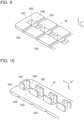
FIG. 9 is a partial perspective view of a second insulator of the second connector portion when viewed from an obliquely upper position. -
FIG. 10 is a partial perspective view of the second insulator of the second connector portion when viewed from an obliquely lower position. -
FIG. 11 is a perspective view of a connecting spring member of the second connector portion when viewed from an obliquely lower position. -
FIG. 12 is a perspective view of a locking spring member of the second connector portion when viewed from an obliquely lower position. -
FIG. 13 is a partial perspective view of the second connector portion when viewed from an obliquely lower position. -
FIG. 14 is a partial perspective view of a sheet type conductive member applied to the connector according toEmbodiment 1, when viewed from an obliquely upper position. -
FIG. 15 is a partial perspective view of the sheet type conductive member applied to the connector according toEmbodiment 1, when viewed from an obliquely lower position. -
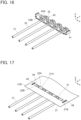
FIG. 16 is a perspective view showing the state where a plurality of electric wires are disposed on the first connector portion according toEmbodiment 1. -
FIG. 17 is a perspective view showing the state where the sheet type conductive member is disposed on the first connector portion according toEmbodiment 1 on which the electric wires are disposed. -
FIG. 18 is a perspective view of a main part of the sheet type conductive member when the second connector portion is fitted to the first connector portion, as viewed from an obliquely upper position. -
FIG. 19 is a perspective view of the main part of the sheet type conductive member when the second connector portion is fitted to the first connector portion, as viewed from an obliquely lower position. -
FIG. 20 is a partial cross-sectional view of the connector assembly using the connector according toEmbodiment 1. -
FIG. 21 is a perspective view showing a first connector portion used in a connector according to a modification ofEmbodiment 1. -
FIG. 22 is a perspective view showing a first connector portion used in a connector according toEmbodiment 2. -
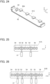
FIG. 23 is a partial front view showing the first connector portion used in the connector according toEmbodiment 2. -
FIG. 24 is a perspective view showing a first connector portion used in a connector according to a modification ofEmbodiment 2. -
FIG. 25 is a view showing the arrangement of a connector and a plurality of electric wires in Arrangement Example 1 ofEmbodiment 3. -
FIG. 26 is a view showing the arrangement of a connector and the electric wires in Arrangement Example 2 ofEmbodiment 3. -
FIG. 27 is a view showing the arrangement of a connector and the electric wires in Arrangement Example 3 ofEmbodiment 3. -
FIG. 28 is a view showing the arrangement of a connector and the electric wires in Arrangement Example 4 ofEmbodiment 3. -
FIG. 29 is a view showing the arrangement of a connector and the electric wires in Arrangement Example 5 ofEmbodiment 3. -
FIG. 30 is a view showing the arrangement of a connector and the electric wires in Arrangement Example 6 ofEmbodiment 3. -
FIG. 31 is a view showing the arrangement of a connector and the electric wires in Arrangement Example 7 ofEmbodiment 3. -
FIG. 32 is a view showing the arrangement of a connector and the electric wires in Arrangement Example 8 ofEmbodiment 3. -
FIG. 33 is a perspective view showing a conventional connector. - Embodiments of the present invention are described below based on the accompanying drawings.
-
FIG. 1 shows a connector assembly using aconnector 11 according toEmbodiment 1. The connector assembly is obtained by connectingconductor portions 32 of a plurality of coatedelectric wires 31 to a sheet typeconductive member 21 by means of aconnector 11. - The sheet type
conductive member 21 includes a sheettype insulating substrate 22, and a plurality of flexible conductors to be described later are formed on the bottom surface of theinsulating substrate 22. - The coated
electric wires 31 are arranged in a predetermined arrangement direction and each extend in a direction perpendicular to the arrangement direction in parallel to the top surface of the sheet typeconductive member 21. Each coatedelectric wire 31 has a structure in which the outer periphery of theconductor portion 32 is covered with aninsulating coating portion 33. Theconductor portions 32 of the coatedelectric wires 31 are electrically connected to the flexible conductors of the sheet typeconductive member 21 by means of theconnector 11. Theconductor portion 32 of the coatedelectric wire 31 may be either a so-called solid wire constituted of one conductor or a so-called stranded wire constituted of plural conductors being stranded. - For convenience, the sheet type
conductive member 21 is defined as extending along an XY plane, the predetermined arrangement direction of the coatedelectric wires 31 is referred to as "X direction (second direction)," the direction in which each coatedelectric wire 31 extends toward theconnector 11 is referred to as "+Y direction (first direction)," and the direction orthogonal to an XY plane is referred to as "Z direction." -
FIGS. 2 and3 show assembly views of the connector assembly. - The
connector 11 is formed of afirst connector portion 41 disposed on the -Z direction side of the sheet typeconductive member 21 and asecond connector portion 51 disposed on the +Z direction side of the sheet typeconductive member 21. Thefirst connector portion 41 faces the bottom surface of the sheet typeconductive member 21, while thesecond connector portion 51 faces the top surface of the sheet typeconductive member 21. - The
conductor portions 32 drawn from the insulatingcoating portions 33 of the coatedelectric wires 31 are disposed between the bottom surface of the sheet typeconductive member 21 and thefirst connector portion 41. - As shown in
FIG. 3 , theflexible conductors 23 corresponding to the coatedelectric wires 31 are exposed on the bottom surface of the sheet typeconductive member 21 facing thefirst connector portion 41. -
FIG. 4 shows the structure of thefirst connector portion 41. Thefirst connector portion 41 is constituted of a first insulator made of an insulating resin material and includes aflat plate portion 42 of rectangular shape extending along an XY plane. A plurality of electricwire retaining portions 43 and a plurality of lockingprojections 44 are arranged alternately in the X direction on the top surface, on the +Z direction side, of theflat plate portion 42. The electricwire retaining portions 43 correspond to the coatedelectric wires 31. - Each electric
wire retaining portion 43 includes: a pair of retainingprojections 43A formed to project on the top surface of theflat plate portion 42 so as to face each other in the X direction (second direction) on the +Y direction side of theflat plate portion 42; and a pair of retainingprojections 43B formed to project on the top surface of theflat plate portion 42 so as to face each other in the X direction (second direction) on the -Y direction side of theflat plate portion 42. Those retainingprojections - The locking
projections 44 are formed to project on the top surface of theflat plate portion 42 at positions spaced from the electricwire retaining portions 43 in the X direction and in a middle portion, in the Y direction, of theflat plate portion 42, and have a substantially prismatic shape. - The
flat plate portion 42 is provided at its opposite ends in the X direction with a pair ofpositioning projections 45 projecting in the +Z direction. Thepositioning projections 45 have a Z directional height larger than that of the retainingprojections projections 44. - As shown in
FIG. 5 , a distance S1 between the pair of retainingprojections 43B in the X direction is formed to be slightly smaller than the diameter of theconductor portion 32 of the coatedelectric wire 31, and the coatedelectric wire 31 is retained by the pair of retainingprojections 43B when theconductor portion 32 of the coatedelectric wire 31 is pushed in between the pair of retainingprojections 43B from the +Z direction. - Likewise, a distance between the pair of retaining
projections 43A in the X direction is formed to be slightly smaller than the diameter of theconductor portion 32 of the coatedelectric wire 31, so that the pair of retainingprojections 43A can retain the coatedelectric wire 31. - The +Z directional end of the locking
projection 44 is provided with a pair of overhangingportions 44A overhanging in the +X and -X directions. -
FIG. 6 shows the structure of thesecond connector portion 51. Thesecond connector portion 51 includes asecond insulator 52 made of an insulating resin material. A plurality of connectingspring members 53 and a plurality of lockingspring members 54 are retained in thesecond insulator 52 to be alternately arranged at predetermined intervals in the X direction. The connectingspring members 53 correspond to the coatedelectric wires 31. -
FIGS. 7 and 8 show assembly views of thesecond connector portion 51. The connectingspring members 53 and thelocking spring members 54 are disposed on the +Z direction side of thesecond insulator 52, and an insulatingsheet 55 is disposed on the +Z direction side of the connectingspring members 53 and thelocking spring members 54. The insulatingsheet 55 is attached to the top surface, on the +Z direction side, of thesecond insulator 52 to thereby retain the connectingspring members 53 and thelocking spring members 54 in thesecond insulator 52. - The
second insulator 52 includes aflat plate portion 52A of rectangular shape extending along an XY plane and a plurality of springmember attachment portions 52B formed to be arranged in the X direction in theflat plate portion 52A. The springmember attachment portions 52B are used to attach the connectingspring members 53 and thelocking spring members 54 to thesecond insulator 52 and all have the same structure without distinguishing between the connectingspring members 53 and thelocking spring members 54. - As shown in
FIG. 9 , each springmember attachment portion 52B includes: a pair of through-holes 52C disposed to be spaced from each other in the X direction and penetrating theflat plate portion 52A in the Z direction; acommunication portion 52D disposed between the pair of through-holes 52C and extending in the Y direction; and agroove portion 52E formed at the top surface, on the +Z direction side, of theflat plate portion 52A and traversing theflat plate portion 52A in the Y direction along thecommunication portion 52D. The top surface, on the +Z direction side, of thecommunication portion 52D forms the same plane with the bottom surface of thegroove portion 52E. - As shown in
FIG. 10 , each springmember attachment portion 52B further includes a pair ofouter wall portions 52F corresponding to the pair of through-holes 52C, the pair ofouter wall portions 52F protruding in the -Z direction on the bottom surface, on the -Z direction side, of theflat plate portion 52A. The pair ofouter wall portions 52F each have a U shape such that the pair ofouter wall portions 52F surround a +X directional portion and -X directional portion of the pair of through-holes 52C when seen from the -Z direction. -
FIG. 11 shows the structure of the connectingspring member 53. The connectingspring member 53 is formed of a bent metal plate and includes: a pair ofspring pieces 53A facing each other in the X direction and being elastically deformable at least in the X direction; and ajoint portion 53B extending along an XY plane and joining the pair ofspring pieces 53A together. The pair ofspring pieces 53A protrude in the -Z direction from thejoint portion 53B and are provided at their -Z directional ends with a pair ofpressing portions 53C that face each other in the X direction.Protrusion portions 53D extend from the opposite ends, in the Y direction, of thejoint portion 53B to protrude in the opposite directions from each other along the Y direction. -
FIG. 12 shows the structure of the lockingspring member 54. The lockingspring member 54 is formed of a bent metal plate and includes: a pair oflock pieces 54A facing each other in the X direction and being elastically deformable in the X direction; and a j ointportion 54B extending along an XY plane and joining the pair oflock pieces 54A together. The pair oflock pieces 54A protrude in the -Z direction from thejoint portion 54B. A pair ofhook portions 54C facing the +Z direction are formed by bending the -Z directional ends of the pair oflock pieces 54A toward the +Z direction and inward within the lockingspring member 54.Protrusion portions 54D extend from the opposite ends, in the Y direction, of thejoint portion 54B to protrude in the opposite directions from each other along the Y direction. - The pair of
spring pieces 53A of the connectingspring member 53 and the pair oflock pieces 54A of the lockingspring member 54 are sized to penetrate through the pair of through-holes 52C of thesecond insulator 52, and theprotrusion portions 53D of the connectingspring member 53 and theprotrusion portions 54D of the lockingspring member 54 are sized to be inserted in thegroove portion 52E of thesecond insulator 52. - When the
second connector portion 51 is assembled, the pairs ofspring pieces 53A of the connectingspring members 53 are passed through the pairs of through-holes 52C of the corresponding springmember attachment portions 52B of thesecond insulator 52 from the +Z direction, and likewise, the pairs oflock pieces 54A of the lockingspring members 54 are passed through the pairs of through-holes 52C of the corresponding springmember attachment portions 52B of thesecond insulator 52 from the +Z direction. In addition, the insulatingsheet 55 is attached to the top surface, on the +Z direction side, of thesecond insulator 52 with theprotrusion portions spring members 53 and thelocking spring members 54 being inserted in thegroove portions 52E of the corresponding springmember attachment portions 52B of thesecond insulator 52. Thus, thesecond connector portion 51 having the connectingspring members 53 and thelocking spring members 54 attached to thesecond insulator 52 can be assembled as shown inFIG. 13 . -
FIG. 14 shows the structure of the sheet typeconductive member 21. A plurality of electricwire connection portions 21A arranged in the X direction are formed in the vicinity of the -Y directional end of the sheet typeconductive member 21. The electricwire connection portions 21A correspond to the coatedelectric wires 31 and each have a pair ofprotrusion pieces 22A formed by cutting out the insulatingsubstrate 22 of the sheet typeconductive member 21. The pair ofprotrusion pieces 22A protrude in the opposite directions from each other in the X direction. Anopening portion 22B penetrating the sheet typeconductive member 21 in the Z direction is formed betweenprotrusion pieces 22A of adjacent electricwire connection portions 21A. - As shown in
FIG. 15 , a contactingportion 23A is formed by theflexible conductor 23 being exposed on the bottom surface, facing the -Z direction, of the pair ofprotrusion pieces 22A of each electricwire connection portion 21A. - The sheet type
conductive member 21 is further provided with a pair ofpositioning holes 21B penetrating the sheet typeconductive member 21 in the Z direction on the +X direction side and the -X direction side of the electricwire connection portions 21A arranged in the X direction. - When the connector assembly is assembled, first, the
conductor portions 32 drawn from the insulatingcoating portions 33 of the coatedelectric wires 31 are separately retained in the corresponding electricwire retaining portions 43 of thefirst connector portion 41 as shown inFIG. 16 . More specifically, eachconductor portion 32 is pushed in between the pair of retainingprojections 43A and between the pair of retainingprojections 43B of the corresponding electricwire retaining portion 43 from the +Z direction and thus retained in the electricwire retaining portion 43. - Next, the sheet type
conductive member 21 is disposed on thefirst connector portion 41 from the +Z direction as shown inFIG. 17 . In this process, the pair ofpositioning projections 45 of thefirst connector portion 41 are passed through the pair ofpositioning holes 21B of the sheet typeconductive member 21, whereby the sheet typeconductive member 21 is positioned with respect to thefirst connector portion 41. In other words, the pair ofprotrusion pieces 22A in each of the electricwire connection portions 21A of the sheet typeconductive member 21 are disposed above a place between the pair of retainingprojections 43A on the +Y direction side and the pair of retainingprojections 43B on the -Y direction side in the corresponding electricwire retaining portion 43 of thefirst connector portion 41. - In this state, the
second connector portion 51 is moved from the +Z direction toward thefirst connector portion 41 and the sheet typeconductive member 21 and fitted to thefirst connector portion 41. In this process, each of the connectingspring members 53 of thesecond connector portion 51 is inserted between the pair of retainingprojections 43A on the +Y direction side and the pair of retainingprojections 43B on the -Y direction side in the corresponding electricwire retaining portion 43 of thefirst connector portion 41 while pushing the pair ofprotrusion pieces 22A in the corresponding electricwire connection portion 21A of the sheet typeconductive member 21 in the -Z direction. The pair ofprotrusion pieces 22A in the corresponding electricwire connection portion 21A of the sheet typeconductive member 21 are pushed in the -Z direction by the pair ofspring pieces 53A of the connectingspring member 53 of thesecond connector portion 51, whereby the pair ofprotrusion pieces 22A and the contactingportion 23A exposed on the bottom surface of thoseprotrusion pieces 22A are bent toward the -Z direction as shown inFIGS. 18 and 19 . - In addition, the pair of
lock pieces 54A of each of the lockingspring members 54 of thesecond connector portion 51 catch on the corresponding lockingprojection 44 of thefirst connector portion 41 through thecorresponding opening portion 22B of the sheet typeconductive member 21. - Thus, the
second connector portion 51 is fitted to thefirst connector portion 41, and the assembling operation of the connector assembly is completed. -
FIG. 20 shows the inside of the connector assembly 20. The contactingportion 23A exposed on the bottom surface of the pair ofprotrusion pieces 22A of the sheet typeconductive member 21 having been pushed in the -Z direction by the pair ofspring pieces 53A of the connectingspring member 53 of thesecond connector portion 51 is, by the pair ofpressing portions 53C of the connectingspring member 53, pressed against theconductor portion 32 of the coatedelectric wire 31 retained by the electricwire retaining portion 43 of thefirst connector portion 41. Consequently, the contactingportion 23A of the sheet typeconductive member 21 makes contact with theconductor portion 32 of the coatedelectric wire 31 at a predetermined contact pressure and is electrically connected thereto. - Meanwhile, as shown in
FIG. 20 , a -Z directional portion of theconductor portion 32 of the coatedelectric wire 31 is diagonally pushed in the X direction and the +Z direction by the pair ofpressing portions 53C of the connectingspring member 53 via the pair ofprotrusion pieces 22A of the sheet typeconductive member 21; accordingly, +Z directional force acts on theconductor portion 32, so that the +Z directional end of theconductor portion 32 is pressed against the contactingportion 23A of the sheet typeconductive member 21. In other words, theconductor portion 32 makes contact with the contactingportion 23A at three points, namely, the +X directional lateral portion and -X directional lateral portion pressed by the pair ofpressing portions 53C and also the +Z directional end, thus achieving reliable electrical connection. However, the contact of the +Z directional end of theconductor portion 32 with the contactingportion 23A is not necessarily required. - When the
second connector portion 51 is fitted to thefirst connector portion 41, the pair oflock pieces 54A of the lockingspring member 54 of thesecond connector portion 51 are pressed against the corresponding lockingprojection 44 of thefirst connector portion 41 and elastically deform, so that the pair ofhook portions 54C catch on the pair of overhangingportions 44A of the lockingprojection 44. - In this manner, the contacting
portions 23A of the electricwire connection portions 21A of the sheet typeconductive member 21 are separately pressed against theconductor portions 32 of the coatedelectric wires 31 retained in thefirst connector portion 41 by the connectingspring members 53 of thesecond connector portion 51 and electrically connected to theconductor portions 32. - Aside from that, the locking
spring members 54 of thesecond connector portion 51 alternating with the connectingspring members 53 separately catch on the lockingprojections 44 of thefirst connector portion 41, whereby the fitting state between thefirst connector portion 41 and thesecond connector portion 51 is locked. - Therefore, the size of the
connector 11 can be reduced, while the contactingportions 23A formed of theflexible conductors 23 of the sheet typeconductive member 21 are electrically connected to theconductor portions 32 of the coatedelectric wires 31 with high reliability. - In addition, the
flexible conductors 23 of the sheet typeconductive member 21 can be electrically connected to theconductor portions 32 of the coatedelectric wires 31 only by a simple connecting operation in which theconductor portions 32 of the coatedelectric wires 31 are pushed in the electricwire retaining portions 43 of thefirst connector portion 41, the sheet typeconductive member 21 is disposed on thefirst connector portion 41, and thesecond connector portion 51 is fitted to thefirst connector portion 41 from the top of the sheet typeconductive member 21. - It should be noted that the connecting
spring member 53 of thesecond connector portion 51 is inserted between the pair of retainingprojections 43A on the +Y direction side and the pair of retainingprojections 43B on the -Y direction side in the corresponding electricwire retaining portion 43 of thefirst connector portion 41; therefore, theconductor portion 32 of the coatedelectric wire 31 retained by the electricwire retaining portion 43 can be connected to the contactingportion 23A of the sheet typeconductive member 21 as long as theconductor portion 32 is drawn from the insulatingcoating portion 33 at least in a position between the pair of retainingprojections 43A on the +Y direction side and the pair of retainingprojections 43B on the -Y direction side. - Thus, the
conductor portion 32 of the coatedelectric wire 31 need not be exposed and may be covered with the insulatingcoating portion 33 in a position pushed in between and retained by the pair of retainingprojections 43A on the +Y direction side of thefirst connector portion 41 and a position pushed in between and retained by the pair of retainingprojections 43B on the -Y direction side thereof. - In
Embodiment 1 above, the electricwire retaining portions 43 of thefirst connector portion 41 each have the pair of retainingprojections 43A disposed on the +Y direction side of theflat plate portion 42 and the pair of retainingprojections 43B disposed on the -Y direction side of theflat plate portion 42; however, the invention is not limited thereto. For instance, each electric wire retaining portion may be formed solely of the pair of retainingprojections 43A disposed on the +Y direction side of theflat plate portion 42, as in afirst connector portion 41A shown inFIG. 21 . Even with thefirst connector portion 41A configured as above, theconductor portions 32 of the coatedelectric wires 31 can be retained and electrically connected to the contactingportions 23A of the sheet typeconductive member 21 in the same manner. - Likewise, each electric wire retaining portion may be formed solely of the pair of retaining
projections 43B disposed on the -Y direction side of theflat plate portion 42 in thefirst connector portion 41 shown inFIG. 4 . - While the retaining
projections first connector portion 41 used inEmbodiment 1 above have a prismatic shape projecting in the +Z direction from the top surface of theflat plate portion 42, the invention is not limited thereto. -
FIG. 22 shows afirst connector portion 41B used in a connector according toEmbodiment 2. In thefirst connector portion 41B, each electric wire retaining portion is formed of asingle retaining projection 46A disposed on the +Y direction side of theflat plate portion 42 and asingle retaining projection 46B disposed on the -Y direction side of theflat plate portion 42 in place of the pair of retainingprojections 43A and the pair of retainingprojections 43B that form each electricwire retaining portion 43 in thefirst connector portion 41 inEmbodiment 1 shown inFIG. 4 . Otherwise, the configuration is the same as that of thefirst connector portion 41 inEmbodiment 1. - As shown in
FIG. 23 , the retainingprojection 46B includes: aprojection body 46C of prismatic shape projecting in the +Z direction from the surface of theflat plate portion 42; and anarm portion 46D extending in the +X direction from the +Z directional end of theprojection body 46C while facing the top surface of theflat plate portion 42. A distance S2 between thearm portion 46D and the top surface of theflat plate portion 42 is formed to be slightly smaller than the diameter of theconductor portion 32 of the coatedelectric wire 31. - The retaining
projection 46A disposed on the +Y direction side of theflat plate portion 42 also has a similar configuration to that of the retainingprojection 46B. Theconductor portion 32 of the coatedelectric wire 31 is pushed in between thearm portion 46D of the retainingprojection 46B and the top surface of theflat plate portion 42 and between thearm portion 46D of the retainingprojection 46A and the surface of theflat plate portion 42 from the +X direction, whereby the coatedelectric wire 31 can be retained by the retainingprojections - Even when the
first connector portion 41B having the retainingprojections first connector portion 41 inEmbodiment 1, similarly, a small-sized connector can be obtained, while the contactingportions 23A formed of theflexible conductors 23 of the sheet typeconductive member 21 are electrically connected to theconductor portions 32 of the coatedelectric wires 31 with high reliability. - In the
first connector portion 41B shown inFIG. 22 , each electric wire retaining portion has thesingle retaining projection 46A disposed on the +Y direction side of theflat plate portion 42 and thesingle retaining projection 46B disposed on the -Y direction side of theflat plate portion 42; however, the invention is not limited thereto. For instance, each electric wire retaining portion may be formed solely of thesingle retaining projection 46A disposed on the +Y direction side of theflat plate portion 42, as in afirst connector portion 41C shown inFIG. 24 . Even with thefirst connector portion 41C configured as above, theconductor portions 32 of the coatedelectric wires 31 can be retained and electrically connected to the contactingportions 23A of the sheet typeconductive member 21 in the same manner. - Likewise, each electric wire retaining portion may be formed solely of the
single retaining projection 46B disposed on the -Y direction side of theflat plate portion 42 in thefirst connector portion 41B shown inFIG. 22 . - While four coated
electric wires 31 connected to the sheet typeconductive member 21 are illustrated inEmbodiments electric wires 31 is not limited to four, and the conductor portion(s) 32 of one or more coatedelectric wires 31 may be connected to the contacting portion(s) 23A formed of the flexible conductor(s) 23 of the sheet typeconductive member 21. - In the
connector 11 ofEmbodiment 1, the electricwire retaining portions 43 and the lockingprojections 44 are alternately arranged in the X direction in thefirst connector portion 41, and also the connectingspring members 53 and thelocking spring members 54 are alternately arranged in the X direction in thesecond connector portion 51. However, the arrangement of the electricwire retaining portions 43 and the lockingprojections 44 and the arrangement of the connectingspring members 53 and thelocking spring members 54 may be modified into various forms. - In a
connector 61A shown inFIG. 25 , the connectingspring members 53 and thelocking spring members 54 are alternately arranged in the X direction in the same manner as inEmbodiment 1. Although not shown inFIG. 25 , the electricwire retaining portions 43 and the lockingprojections 44 are also arranged in the X direction to correspond to the connectingspring members 53 and thelocking spring members 54. - Since the fitting state of the
connector 61A is locked by the lockingspring members 54 alternating with the connectingspring members 53, the contactingportions 23A of the sheet typeconductive member 21 can be electrically connected to theconductor portions 32 of the coatedelectric wires 31 by means of the connectingspring members 53 with high reliability. - In a
connector 61B shown inFIG. 26 , the lockingspring member 54 is disposed on each of the opposite sides, in the X direction, of every two connectingspring members 53 arranged in series in the X direction. Although not shown inFIG. 26 , the electricwire retaining portions 43 and the lockingprojections 44 are also arranged in the X direction to correspond to the connectingspring members 53 and thelocking spring members 54. - Even with this arrangement, the fitting state of the
connector 61B is locked by the lockingspring member 54 for every two connectingspring members 53, and the contactingportions 23A of the sheet typeconductive member 21 can be electrically connected to theconductor portions 32 of the coatedelectric wires 31 by means of the connectingspring members 53 with high reliability. - In a
connector 61C shown inFIG. 27 , the connectingspring members 53 and thelocking spring members 54 are arranged in the X direction in two rows at a distance in the Y direction and staggered in the Y direction. In each row, the connectingspring members 53 and thelocking spring members 54 are alternately arranged in the X direction. Although not shown inFIG. 27 , the electricwire retaining portions 43 and the lockingprojections 44 are also arranged to correspond to the connectingspring members 53 and thelocking spring members 54. - Since the connecting
spring members 53 and thelocking spring members 54 are staggered in the Y direction, the coatedelectric wires 31 can be arranged on the -Y direction side of theconnector 61C such that theirconductor portions 32 extend to the corresponding connectingspring members 53. - This arrangement makes it possible to connect the
conductor portions 32 of a large number of coatedelectric wires 31 to the sheet typeconductive member 21. - In a
connector 61D shown inFIG. 28 , the connectingspring members 53 and thelocking spring members 54 are arranged in the X direction in two rows at a distance in the Y direction and staggered in the Y direction, similarly to theconnector 61C shown inFIG. 27 . In each row, however, the lockingspring member 54 is disposed on each of the opposite sides, in the X direction, of every two connectingspring members 53 arranged in series in the X direction. Although not shown inFIG. 28 , the electricwire retaining portions 43 and the lockingprojections 44 are also arranged to correspond to the connectingspring members 53 and thelocking spring members 54. - Even with this configuration, since the connecting
spring members 53 and thelocking spring members 54 are staggered in the Y direction, the coatedelectric wires 31 can be arranged on the -Y direction side of theconnector 61D such that theirconductor portions 32 extend to the corresponding connectingspring members 53. Besides, theconductor portions 32 of a large number of coatedelectric wires 31 can be connected to the sheet typeconductive member 21. - In a
connector 61E shown inFIG. 29 , the connectingspring members 53 and thelocking spring members 54 are arranged in the X direction in two rows at a distance in the Y direction and aligned in the Y direction. In addition, the connectingspring members 53 arranged in, of the two rows, one row are placed in the same X-directional positions as those of the connectingspring members 53 arranged in the other row. Although not shown inFIG. 29 , the electricwire retaining portions 43 and the lockingprojections 44 are also arranged to correspond to the connectingspring members 53 and thelocking spring members 54. - Since the connecting
spring members 53 and thelocking spring members 54 are aligned in the Y direction, the coatedelectric wires 31 are arranged on each of the +Y direction side and the -Y direction side of theconnector 61E. - Even with this arrangement, the
conductor portions 32 of a large number of coatedelectric wires 31 can be connected to the sheet typeconductive member 21. - In a
connector 61F shown inFIG. 30 , the connectingspring members 53 and thelocking spring members 54 are arranged in the X direction in two rows at a distance in the Y direction and aligned in the Y direction, similarly to theconnector 61E shown inFIG. 29 . However, the connectingspring members 53 arranged in, of the two rows, one row and the connectingspring members 53 arranged in the other row are staggered in the Y direction. Although not shown inFIG. 30 , the electricwire retaining portions 43 and the lockingprojections 44 are also arranged to correspond to the connectingspring members 53 and thelocking spring members 54. - Also in this case, since the connecting
spring members 53 and thelocking spring members 54 are aligned in the Y direction, the coatedelectric wires 31 are arranged on each of the +Y direction side and the -Y direction side of theconnector 61F. - Even with this arrangement, the
conductor portions 32 of a large number of coatedelectric wires 31 can be connected to the sheet typeconductive member 21. - Also in a
connector 61G shown inFIG. 31 , the connectingspring members 53 and thelocking spring members 54 are arranged in the X direction in two rows at a distance in the Y direction and aligned in the Y direction, similarly to theconnector 61E shown inFIG. 29 . In each row, however, the lockingspring member 54 is disposed on each of the opposite sides, in the X direction, of every two connectingspring members 53 arranged in series in the X direction. Although not shown inFIG. 31 , the electricwire retaining portions 43 and the lockingprojections 44 are also arranged to correspond to the connectingspring members 53 and thelocking spring members 54. - Also in this case, since the connecting
spring members 53 and thelocking spring members 54 are aligned in the Y direction, the coatedelectric wires 31 are arranged on each of the +Y direction side and the -Y direction side of theconnector 61G. - Even with this arrangement, the
conductor portions 32 of a large number of coatedelectric wires 31 can be connected to the sheet typeconductive member 21. - Also in a
connector 61H shown inFIG. 32 , the connectingspring members 53 and thelocking spring members 54 are arranged in the X direction in two rows at a distance in the Y direction and aligned in the Y direction. In each row, however, the lockingspring member 54 is disposed on each of the opposite sides, in the X direction, of every three connectingspring members 53 arranged in series in the X direction. Although not shown inFIG. 32 , the electricwire retaining portions 43 and the lockingprojections 44 are also arranged to correspond to the connectingspring members 53 and thelocking spring members 54. - Since the connecting
spring members 53 and thelocking spring members 54 are aligned in the Y direction, the coatedelectric wires 31 are arranged on each of the +Y direction side and the -Y direction side of theconnector 61H. - Even with this arrangement, the fitting state of the
connector 61H is locked by the lockingspring member 54 for every three connectingspring members 53, and the contactingportions 23A of the sheet typeconductive member 21 can be electrically connected to theconductor portions 32 of the coatedelectric wires 31 by means of the connectingspring members 53 with high reliability.
Claims (14)
- A connector (11, 61A, 61B, 61C, 61D, 61E, 61F, 61G, 61H) connecting a conductor portion (32) of an electric wire (31) to a flexible conductor (23) of a sheet type conductive member (21), the connector comprising:a first connector portion (41, 41A, 41B, 41C) including an electric wire retaining portion (43) used to retain the electric wire, and a locking projection (44); anda second connector portion (51) including a connecting spring member (53) corresponding to the electric wire retained by the electric wire retaining portion, and a locking spring member (54) corresponding to the locking projection,wherein the electric wire extends along a first direction,the connecting spring member and the locking spring member are disposed at a predetermined interval in a second direction perpendicular to the first direction, andwhen the second connector portion is fitted to the first connector portion having the electric wire retained in the electric wire retaining portion with the sheet type conductive member being interposed between the second connector portion and the first connector portion, the flexible conductor (23) of the sheet type conductive member is pressed against the conductor portion (32) of the electric wire by the connecting spring member (53) and electrically connected to the conductor portion, and the locking spring member (54) catches on the locking projection (44) so that a fitting state between the first connector portion (41, 41A, 41B, 41C) and the second connector portion (51) is locked.
- The connector (11) according to claim 1,
wherein the first connector portion (41, 41A, 41B, 41C) is constituted of a first insulator in which the electric wire retaining portion (43) and the locking projection (44) are formed on a top surface of a flat plate portion (42) extending along the first direction and the second direction. - The connector (11) according to claim 2,
wherein the electric wire retaining portion (43) includes at least a pair of retaining projections (43A, 43B) that face each other in the second direction and sandwich an outer peripheral portion of the electric wire. - The connector (11) according to claim 2,
wherein the electric wire retaining portion (43) includes at least one retaining projection (46A, 46B) provided with an arm portion (46D) that extends in the second direction while facing the top surface of the flat plate portion (42) and that holds an outer peripheral portion of the electric wire between itself and the top surface of the flat plate portion. - The connector (11) according to any one of claims 1-4,
wherein the second connector portion (51) includes: a second insulator (52) to which the connecting spring member and the locking spring member are attached; and an insulating sheet (55) that is attached to the second insulator to thereby retain the connecting spring member and the locking spring member in the second insulator. - The connector (11) according to any one of claims 1-5,wherein the locking projection (44) includes an overhanging portion (44A) overhanging in the second direction,the locking spring member (54) includes a lock piece (54A) that is elastically deformable in the second direction, andthe lock piece catches on the overhanging portion when the second connector portion is fitted to the first connector portion.
- The connector (11) according to claim 6,wherein the locking projection (44) includes a pair of the overhanging portions (44A) overhanging in opposite directions from each other, andthe locking spring member (54) includes a pair of the lock pieces (54A) that separately catch on the pair of the overhanging portions.
- The connector (11) according to any one of claims 1-7,
wherein the connecting spring member (53) includes a pair of spring pieces (53A) facing each other in the second direction and presses the flexible conductor (23) of the sheet type conductive member to the conductor portion (32) of the electric wire disposed between the pair of spring pieces. - The connector (11) according to any one of claims 2-4,wherein the first connector portion (41, 41A, 41B, 41C) includes a pair of positioning projections (45) disposed on opposite ends, in the second direction, of the flat plat portion and projecting in a fitting direction in which the first connector portion and the second connector portion are fitted together, andthe pair of positioning projections (45) are passed through a pair of positioning holes (21B) formed in the sheet type conductive member (21), whereby the sheet type conductive member is positioned with respect to the first connector portion.
- The connector (61A, 61B) according to any one of claims 1-9,wherein the second connector portion (51) includes a plurality of the connecting spring members (53) and a plurality of the locking spring members (54) arranged in the second direction,the locking spring member is disposed on each of opposite sides, in the second direction, of every one or more connecting spring members arranged in series in the second direction, andthe first connector portion (41, 41A, 41B, 41C) has a plurality of the electric wire retaining portions (43) and a plurality of the locking projections (44) that are arranged in the second direction to correspond to the plurality of the connecting spring members and the plurality of the locking spring members.
- The connector (61C, 61D, 61E, 61F, 61G, 61H) according to claim 10,wherein the second connector portion (51) has the plurality of the connecting spring members (53) and the plurality of the locking spring members (54) arranged in the second direction in two rows at a distance in the first direction, andthe first connector portion (41, 41B) has the plurality of the electric wire retaining portions (43) and the plurality of the locking projections (44) that are arranged in the second direction in two rows to correspond to the plurality of the connecting spring members and the plurality of the locking spring members.
- The connector (61C, 61D) according to claim 11,wherein the plurality of the connecting spring members (53) and the plurality of the locking spring members (54) arranged in the two rows are staggered in the first direction, andthe plurality of the electric wire retaining portions (43) and the plurality of the locking projections (44) arranged in the two rows are staggered in the first direction.
- The connector (61E, 61F, 61G, 61H) according to claim 11,wherein the plurality of the connecting spring members (53) and the plurality of the locking spring members (54) arranged in the two rows are aligned in the first direction, andthe plurality of the electric wire retaining portions (43) and the plurality of the locking projections (44) arranged in the two rows are aligned in the first direction.
- A connector assembly comprising:the sheet type conductive member (21);the electric wire (31); andthe connector (11, 61A, 61B, 61C, 61D, 61E, 61F, 61G, 61H) according to any one of claims 1-13,wherein the flexible conductor (23) of the sheet type conductive member is pressed against the conductor portion (32) of the electric wire by the connecting spring member (53) and electrically connected to the conductor portion, and the locking spring member (54) catches on the locking projection (44) so that a fitting state between the first connector portion (41, 41A, 41B, 41C) and the second connector portion (51) is locked.
Applications Claiming Priority (1)
| Application Number | Priority Date | Filing Date | Title |
|---|---|---|---|
| JP2023022654A JP7898398B2 (en) | 2023-02-16 | 2023-02-16 | Connectors and connector assemblies |
Publications (2)
| Publication Number | Publication Date |
|---|---|
| EP4418467A1 true EP4418467A1 (en) | 2024-08-21 |
| EP4418467B1 EP4418467B1 (en) | 2025-04-02 |
Family
ID=89121539
Family Applications (1)
| Application Number | Title | Priority Date | Filing Date |
|---|---|---|---|
| EP23214584.7A Active EP4418467B1 (en) | 2023-02-16 | 2023-12-06 | Connector and connector assembly |
Country Status (4)
| Country | Link |
|---|---|
| US (1) | US12646867B2 (en) |
| EP (1) | EP4418467B1 (en) |
| JP (1) | JP7898398B2 (en) |
| CN (1) | CN118508131A (en) |
Families Citing this family (1)
| Publication number | Priority date | Publication date | Assignee | Title |
|---|---|---|---|---|
| JP2024065476A (en) * | 2022-10-31 | 2024-05-15 | 日本航空電子工業株式会社 | Connector and connector assembly |
Citations (4)
| Publication number | Priority date | Publication date | Assignee | Title |
|---|---|---|---|---|
| JPS52147261U (en) * | 1976-05-01 | 1977-11-08 | ||
| JP2007214087A (en) | 2006-02-13 | 2007-08-23 | Fujikura Ltd | connector |
| EP3683895A1 (en) * | 2019-01-21 | 2020-07-22 | Japan Aviation Electronics Industry, Limited | Connector, circuit board assembly and connection structure |
| EP4120480A1 (en) * | 2021-07-14 | 2023-01-18 | Japan Aviation Electronics Industry, Ltd. | Connector and connector assembly |
Family Cites Families (7)
| Publication number | Priority date | Publication date | Assignee | Title |
|---|---|---|---|---|
| GB1191838A (en) * | 1966-09-21 | 1970-05-13 | Lucas Industries Ltd | Electrical Connectors |
| JPS5743335Y2 (en) * | 1975-07-25 | 1982-09-24 | ||
| US4902252A (en) * | 1988-10-31 | 1990-02-20 | Signeon Corporation | High voltage electrical connector |
| DE19654523C2 (en) * | 1996-12-19 | 2003-10-09 | Wago Verwaltungs Gmbh | Connection terminal with at least two terminal points for connecting electrical conductors |
| US8192226B2 (en) * | 2009-09-29 | 2012-06-05 | Ideal Industries, Inc. | One-piece conductive clip for push-in wire connector |
| WO2012083049A1 (en) | 2010-12-17 | 2012-06-21 | First Solar, Inc | Electrical connection system |
| US11258189B2 (en) * | 2019-10-03 | 2022-02-22 | Japan Aviation Electronics Industry, Limited | Connector and connecting method |
-
2023
- 2023-02-16 JP JP2023022654A patent/JP7898398B2/en active Active
- 2023-12-05 US US18/529,278 patent/US12646867B2/en active Active
- 2023-12-06 EP EP23214584.7A patent/EP4418467B1/en active Active
- 2023-12-07 CN CN202311674497.0A patent/CN118508131A/en active Pending
Patent Citations (4)
| Publication number | Priority date | Publication date | Assignee | Title |
|---|---|---|---|---|
| JPS52147261U (en) * | 1976-05-01 | 1977-11-08 | ||
| JP2007214087A (en) | 2006-02-13 | 2007-08-23 | Fujikura Ltd | connector |
| EP3683895A1 (en) * | 2019-01-21 | 2020-07-22 | Japan Aviation Electronics Industry, Limited | Connector, circuit board assembly and connection structure |
| EP4120480A1 (en) * | 2021-07-14 | 2023-01-18 | Japan Aviation Electronics Industry, Ltd. | Connector and connector assembly |
Also Published As
| Publication number | Publication date |
|---|---|
| CN118508131A (en) | 2024-08-16 |
| JP2024116839A (en) | 2024-08-28 |
| US12646867B2 (en) | 2026-06-02 |
| US20240283172A1 (en) | 2024-08-22 |
| JP7898398B2 (en) | 2026-07-31 |
| EP4418467B1 (en) | 2025-04-02 |
Similar Documents
| Publication | Publication Date | Title |
|---|---|---|
| US10096918B1 (en) | Connector | |
| EP4002597B1 (en) | Connector | |
| US12300919B2 (en) | Connector and connecting method | |
| EP3435490B1 (en) | Connection assisting member and circuit board assembly | |
| US4270831A (en) | Electric terminal for press-in connection with conductors | |
| JP7822290B2 (en) | connector | |
| EP4418467B1 (en) | Connector and connector assembly | |
| EP4507128B1 (en) | Connector and connector assembly | |
| EP4395079A1 (en) | Connector and connecting method | |
| EP4611180A1 (en) | Connector | |
| US12537336B2 (en) | Connector | |
| JP7216556B2 (en) | Covered Conductor Connection Method, Covered Conductor Connection Structure, and Covered Conductor Connection Member | |
| EP3683895A1 (en) | Connector, circuit board assembly and connection structure | |
| JP2003272736A (en) | Electrical connector | |
| EP4362233B1 (en) | Connector and connector assembly | |
| EP4379964A1 (en) | Connector assembly and connecting method | |
| US20060084295A1 (en) | Connector system for conductive plates | |
| CN222191147U (en) | A wire connection structure and a quick-acting switch | |
| KR200302449Y1 (en) | A terminal | |
| EP4346013A1 (en) | Connector, connector assembly, and connecting method | |
| JP2736603B2 (en) | ZIF connector | |
| JP5137654B2 (en) | Connection terminal connection structure and connection method | |
| JPH0328025B2 (en) | ||
| JPH04135164U (en) | conductive terminal | |
| JPH056694U (en) | Conductive terminal |
Legal Events
| Date | Code | Title | Description |
|---|---|---|---|
| PUAI | Public reference made under article 153(3) epc to a published international application that has entered the european phase |
Free format text: ORIGINAL CODE: 0009012 |
|
| STAA | Information on the status of an ep patent application or granted ep patent |
Free format text: STATUS: REQUEST FOR EXAMINATION WAS MADE |
|
| 17P | Request for examination filed |
Effective date: 20231206 |
|
| AK | Designated contracting states |
Kind code of ref document: A1 Designated state(s): AL AT BE BG CH CY CZ DE DK EE ES FI FR GB GR HR HU IE IS IT LI LT LU LV MC ME MK MT NL NO PL PT RO RS SE SI SK SM TR |
|
| RBV | Designated contracting states (corrected) |
Designated state(s): AL AT BE BG CH CY CZ DE DK EE ES FI FR GB GR HR HU IE IS IT LI LT LU LV MC ME MK MT NL NO PL PT RO RS SE SI SK SM TR |
|
| RAP3 | Party data changed (applicant data changed or rights of an application transferred) |
Owner name: JAPAN AVIATION ELECTRONICS INDUSTRY, LIMITED |
|
| GRAP | Despatch of communication of intention to grant a patent |
Free format text: ORIGINAL CODE: EPIDOSNIGR1 |
|
| STAA | Information on the status of an ep patent application or granted ep patent |
Free format text: STATUS: GRANT OF PATENT IS INTENDED |
|
| RIC1 | Information provided on ipc code assigned before grant |
Ipc: H01R 4/50 20060101ALN20241118BHEP Ipc: H01R 107/00 20060101ALN20241118BHEP Ipc: H01R 4/48 20060101ALN20241118BHEP Ipc: H01R 12/63 20110101ALI20241118BHEP Ipc: H01R 12/65 20110101AFI20241118BHEP |
|
| INTG | Intention to grant announced |
Effective date: 20241128 |
|
| GRAS | Grant fee paid |
Free format text: ORIGINAL CODE: EPIDOSNIGR3 |
|
| GRAA | (expected) grant |
Free format text: ORIGINAL CODE: 0009210 |
|
| STAA | Information on the status of an ep patent application or granted ep patent |
Free format text: STATUS: THE PATENT HAS BEEN GRANTED |
|
| AK | Designated contracting states |
Kind code of ref document: B1 Designated state(s): AL AT BE BG CH CY CZ DE DK EE ES FI FR GB GR HR HU IE IS IT LI LT LU LV MC ME MK MT NL NO PL PT RO RS SE SI SK SM TR |
|
| REG | Reference to a national code |
Ref country code: GB Ref legal event code: FG4D |
|
| REG | Reference to a national code |
Ref country code: CH Ref legal event code: EP |
|
| REG | Reference to a national code |
Ref country code: IE Ref legal event code: FG4D |
|
| REG | Reference to a national code |
Ref country code: DE Ref legal event code: R096 Ref document number: 602023002729 Country of ref document: DE |
|
| REG | Reference to a national code |
Ref country code: NL Ref legal event code: MP Effective date: 20250402 |
|
| PG25 | Lapsed in a contracting state [announced via postgrant information from national office to epo] |
Ref country code: NL Free format text: LAPSE BECAUSE OF FAILURE TO SUBMIT A TRANSLATION OF THE DESCRIPTION OR TO PAY THE FEE WITHIN THE PRESCRIBED TIME-LIMIT Effective date: 20250402 |
|
| REG | Reference to a national code |
Ref country code: AT Ref legal event code: MK05 Ref document number: 1782263 Country of ref document: AT Kind code of ref document: T Effective date: 20250402 |
|
| PG25 | Lapsed in a contracting state [announced via postgrant information from national office to epo] |
Ref country code: FI Free format text: LAPSE BECAUSE OF FAILURE TO SUBMIT A TRANSLATION OF THE DESCRIPTION OR TO PAY THE FEE WITHIN THE PRESCRIBED TIME-LIMIT Effective date: 20250402 Ref country code: ES Free format text: LAPSE BECAUSE OF FAILURE TO SUBMIT A TRANSLATION OF THE DESCRIPTION OR TO PAY THE FEE WITHIN THE PRESCRIBED TIME-LIMIT Effective date: 20250402 Ref country code: PT Free format text: LAPSE BECAUSE OF FAILURE TO SUBMIT A TRANSLATION OF THE DESCRIPTION OR TO PAY THE FEE WITHIN THE PRESCRIBED TIME-LIMIT Effective date: 20250804 |
|
| REG | Reference to a national code |
Ref country code: LT Ref legal event code: MG9D |
|
| PG25 | Lapsed in a contracting state [announced via postgrant information from national office to epo] |
Ref country code: GR Free format text: LAPSE BECAUSE OF FAILURE TO SUBMIT A TRANSLATION OF THE DESCRIPTION OR TO PAY THE FEE WITHIN THE PRESCRIBED TIME-LIMIT Effective date: 20250703 Ref country code: NO Free format text: LAPSE BECAUSE OF FAILURE TO SUBMIT A TRANSLATION OF THE DESCRIPTION OR TO PAY THE FEE WITHIN THE PRESCRIBED TIME-LIMIT Effective date: 20250702 |
|
| PG25 | Lapsed in a contracting state [announced via postgrant information from national office to epo] |
Ref country code: PL Free format text: LAPSE BECAUSE OF FAILURE TO SUBMIT A TRANSLATION OF THE DESCRIPTION OR TO PAY THE FEE WITHIN THE PRESCRIBED TIME-LIMIT Effective date: 20250402 |
|
| PG25 | Lapsed in a contracting state [announced via postgrant information from national office to epo] |
Ref country code: BG Free format text: LAPSE BECAUSE OF FAILURE TO SUBMIT A TRANSLATION OF THE DESCRIPTION OR TO PAY THE FEE WITHIN THE PRESCRIBED TIME-LIMIT Effective date: 20250402 |
|
| PG25 | Lapsed in a contracting state [announced via postgrant information from national office to epo] |
Ref country code: HR Free format text: LAPSE BECAUSE OF FAILURE TO SUBMIT A TRANSLATION OF THE DESCRIPTION OR TO PAY THE FEE WITHIN THE PRESCRIBED TIME-LIMIT Effective date: 20250402 |
|
| PG25 | Lapsed in a contracting state [announced via postgrant information from national office to epo] |
Ref country code: AT Free format text: LAPSE BECAUSE OF FAILURE TO SUBMIT A TRANSLATION OF THE DESCRIPTION OR TO PAY THE FEE WITHIN THE PRESCRIBED TIME-LIMIT Effective date: 20250402 |
|
| PG25 | Lapsed in a contracting state [announced via postgrant information from national office to epo] |
Ref country code: RS Free format text: LAPSE BECAUSE OF FAILURE TO SUBMIT A TRANSLATION OF THE DESCRIPTION OR TO PAY THE FEE WITHIN THE PRESCRIBED TIME-LIMIT Effective date: 20250702 |
|
| PG25 | Lapsed in a contracting state [announced via postgrant information from national office to epo] |
Ref country code: IS Free format text: LAPSE BECAUSE OF FAILURE TO SUBMIT A TRANSLATION OF THE DESCRIPTION OR TO PAY THE FEE WITHIN THE PRESCRIBED TIME-LIMIT Effective date: 20250802 |
|
| PG25 | Lapsed in a contracting state [announced via postgrant information from national office to epo] |
Ref country code: LV Free format text: LAPSE BECAUSE OF FAILURE TO SUBMIT A TRANSLATION OF THE DESCRIPTION OR TO PAY THE FEE WITHIN THE PRESCRIBED TIME-LIMIT Effective date: 20250402 |
|
| REG | Reference to a national code |
Ref country code: DE Ref legal event code: R097 Ref document number: 602023002729 Country of ref document: DE |
|
| PGFP | Annual fee paid to national office [announced via postgrant information from national office to epo] |
Ref country code: DE Payment date: 20251028 Year of fee payment: 3 |
|
| PG25 | Lapsed in a contracting state [announced via postgrant information from national office to epo] |
Ref country code: DK Free format text: LAPSE BECAUSE OF FAILURE TO SUBMIT A TRANSLATION OF THE DESCRIPTION OR TO PAY THE FEE WITHIN THE PRESCRIBED TIME-LIMIT Effective date: 20250402 Ref country code: SM Free format text: LAPSE BECAUSE OF FAILURE TO SUBMIT A TRANSLATION OF THE DESCRIPTION OR TO PAY THE FEE WITHIN THE PRESCRIBED TIME-LIMIT Effective date: 20250402 |
|
| PGFP | Annual fee paid to national office [announced via postgrant information from national office to epo] |
Ref country code: FR Payment date: 20251117 Year of fee payment: 3 |
|
| PG25 | Lapsed in a contracting state [announced via postgrant information from national office to epo] |
Ref country code: CZ Free format text: LAPSE BECAUSE OF FAILURE TO SUBMIT A TRANSLATION OF THE DESCRIPTION OR TO PAY THE FEE WITHIN THE PRESCRIBED TIME-LIMIT Effective date: 20250402 |
|
| PG25 | Lapsed in a contracting state [announced via postgrant information from national office to epo] |
Ref country code: EE Free format text: LAPSE BECAUSE OF FAILURE TO SUBMIT A TRANSLATION OF THE DESCRIPTION OR TO PAY THE FEE WITHIN THE PRESCRIBED TIME-LIMIT Effective date: 20250402 |
|
| PG25 | Lapsed in a contracting state [announced via postgrant information from national office to epo] |
Ref country code: SK Free format text: LAPSE BECAUSE OF FAILURE TO SUBMIT A TRANSLATION OF THE DESCRIPTION OR TO PAY THE FEE WITHIN THE PRESCRIBED TIME-LIMIT Effective date: 20250402 |
|
| PG25 | Lapsed in a contracting state [announced via postgrant information from national office to epo] |
Ref country code: IT Free format text: LAPSE BECAUSE OF FAILURE TO SUBMIT A TRANSLATION OF THE DESCRIPTION OR TO PAY THE FEE WITHIN THE PRESCRIBED TIME-LIMIT Effective date: 20250402 |
|
| PLBE | No opposition filed within time limit |
Free format text: ORIGINAL CODE: 0009261 |
|
| STAA | Information on the status of an ep patent application or granted ep patent |
Free format text: STATUS: NO OPPOSITION FILED WITHIN TIME LIMIT |
|
| REG | Reference to a national code |
Ref country code: CH Ref legal event code: L10 Free format text: ST27 STATUS EVENT CODE: U-0-0-L10-L00 (AS PROVIDED BY THE NATIONAL OFFICE) Effective date: 20260211 |
|
| PG25 | Lapsed in a contracting state [announced via postgrant information from national office to epo] |
Ref country code: RO Free format text: LAPSE BECAUSE OF FAILURE TO SUBMIT A TRANSLATION OF THE DESCRIPTION OR TO PAY THE FEE WITHIN THE PRESCRIBED TIME-LIMIT Effective date: 20250402 |
|
| 26N | No opposition filed |
Effective date: 20260105 |
|
| PG25 | Lapsed in a contracting state [announced via postgrant information from national office to epo] |
Ref country code: LT Free format text: LAPSE BECAUSE OF FAILURE TO SUBMIT A TRANSLATION OF THE DESCRIPTION OR TO PAY THE FEE WITHIN THE PRESCRIBED TIME-LIMIT Effective date: 20250402 |
|
| PG25 | Lapsed in a contracting state [announced via postgrant information from national office to epo] |
Ref country code: MC Free format text: LAPSE BECAUSE OF FAILURE TO SUBMIT A TRANSLATION OF THE DESCRIPTION OR TO PAY THE FEE WITHIN THE PRESCRIBED TIME-LIMIT Effective date: 20250402 |
|
| PG25 | Lapsed in a contracting state [announced via postgrant information from national office to epo] |
Ref country code: SE Free format text: LAPSE BECAUSE OF FAILURE TO SUBMIT A TRANSLATION OF THE DESCRIPTION OR TO PAY THE FEE WITHIN THE PRESCRIBED TIME-LIMIT Effective date: 20250402 |