EP4418461A1 - Antenna and antenna array - Google Patents
Antenna and antenna array Download PDFInfo
- Publication number
- EP4418461A1 EP4418461A1 EP23157528.3A EP23157528A EP4418461A1 EP 4418461 A1 EP4418461 A1 EP 4418461A1 EP 23157528 A EP23157528 A EP 23157528A EP 4418461 A1 EP4418461 A1 EP 4418461A1
- Authority
- EP
- European Patent Office
- Prior art keywords
- reflectors
- antenna
- tangential
- blended
- double
- Prior art date
- Legal status (The legal status is an assumption and is not a legal conclusion. Google has not performed a legal analysis and makes no representation as to the accuracy of the status listed.)
- Pending
Links
Images



Classifications
-
- H—ELECTRICITY
- H01—ELECTRIC ELEMENTS
- H01Q—ANTENNAS, i.e. RADIO AERIALS
- H01Q21/00—Antenna arrays or systems
- H01Q21/06—Arrays of individually energised antenna units similarly polarised and spaced apart
-
- G—PHYSICS
- G01—MEASURING; TESTING
- G01S—RADIO DIRECTION-FINDING; RADIO NAVIGATION; DETERMINING DISTANCE OR VELOCITY BY USE OF RADIO WAVES; LOCATING OR PRESENCE-DETECTING BY USE OF THE REFLECTION OR RERADIATION OF RADIO WAVES; ANALOGOUS ARRANGEMENTS USING OTHER WAVES
- G01S3/00—Direction-finders for determining the direction from which infrasonic, sonic, ultrasonic or electromagnetic waves, or particle emission, not having a directional significance, are being received
- G01S3/02—Direction-finders for determining the direction from which infrasonic, sonic, ultrasonic or electromagnetic waves, or particle emission, not having a directional significance, are being received using radio waves
- G01S3/04—Details
- G01S3/043—Receivers
-
- H—ELECTRICITY
- H01—ELECTRIC ELEMENTS
- H01Q—ANTENNAS, i.e. RADIO AERIALS
- H01Q1/00—Details of, or arrangements associated with, antennas
- H01Q1/36—Structural form of radiating elements, e.g. cone, spiral, umbrella; Particular materials used therewith
-
- H—ELECTRICITY
- H01—ELECTRIC ELEMENTS
- H01Q—ANTENNAS, i.e. RADIO AERIALS
- H01Q15/00—Devices for reflection, refraction, diffraction or polarisation of waves radiated from an antenna, e.g. quasi-optical devices
- H01Q15/14—Reflecting surfaces; Equivalent structures
- H01Q15/16—Reflecting surfaces; Equivalent structures curved in two dimensions [2D], e.g. paraboloidal
-
- H—ELECTRICITY
- H01—ELECTRIC ELEMENTS
- H01Q—ANTENNAS, i.e. RADIO AERIALS
- H01Q15/00—Devices for reflection, refraction, diffraction or polarisation of waves radiated from an antenna, e.g. quasi-optical devices
- H01Q15/14—Reflecting surfaces; Equivalent structures
- H01Q15/16—Reflecting surfaces; Equivalent structures curved in two dimensions [2D], e.g. paraboloidal
- H01Q15/165—Reflecting surfaces; Equivalent structures curved in two dimensions [2D], e.g. paraboloidal composed of a plurality of rigid panels
-
- H—ELECTRICITY
- H01—ELECTRIC ELEMENTS
- H01Q—ANTENNAS, i.e. RADIO AERIALS
- H01Q21/00—Antenna arrays or systems
- H01Q21/06—Arrays of individually energised antenna units similarly polarised and spaced apart
- H01Q21/20—Arrays of individually energised antenna units similarly polarised and spaced apart the units being spaced along or adjacent to a curvilinear path
-
- H—ELECTRICITY
- H01—ELECTRIC ELEMENTS
- H01Q—ANTENNAS, i.e. RADIO AERIALS
- H01Q21/00—Antenna arrays or systems
- H01Q21/06—Arrays of individually energised antenna units similarly polarised and spaced apart
- H01Q21/20—Arrays of individually energised antenna units similarly polarised and spaced apart the units being spaced along or adjacent to a curvilinear path
- H01Q21/205—Arrays of individually energised antenna units similarly polarised and spaced apart the units being spaced along or adjacent to a curvilinear path providing an omnidirectional coverage
-
- H—ELECTRICITY
- H01—ELECTRIC ELEMENTS
- H01Q—ANTENNAS, i.e. RADIO AERIALS
- H01Q9/00—Electrically-short antennas having dimensions not more than twice the operating wavelength and consisting of conductive active radiating elements
- H01Q9/04—Resonant antennas
- H01Q9/30—Resonant antennas with feed to end of elongated active element, e.g. unipole
- H01Q9/40—Element having extended radiating surface
Definitions
- the invention relates to an antenna and an antenna array.
- the invention relates to an antenna and an antenna array for direction finding, especially wideband direction finding.
- Document US 5,270,726 A relates to a compact range system including a feed antenna offset from the rectangular-aperture paraboloidal reflector.
- the reflector has blended edges and smoothed corners to reduce contamination of propagated electromagnetic plane waves by diffracted energy.
- the continuous, smooth surface of the reflector should maximize the purity and uniformity of the plane waves from the reflector.
- said document does not even recognize the problem that for wideband antennas with a cavity or reflector, respectively, behind the corresponding driving element, the edges of the reflector act as radiating sources. Disadvantageously, this results in strong sidelobes at +-90 degrees from the boresight or main direction, respectively, thereby not allowing for an accurate and efficient direction finding.
- an antenna comprises at least two radiating elements with at least two reflectors offset from the at least two radiating elements.
- at least two adjacent reflectors of the at least two reflectors are connected with a double-tangential blended elliptical surface.
- the antenna can be a Compact Antenna Test Range (CATR) antenna especially such that the CATR antenna or a dual CATR system, respectively, can be milled from a single metal block.
- CATR Compact Antenna Test Range
- the double-tangential blended elliptical surface comprises or is a double-tangential blended elliptical reflector.
- the antenna is used for direction finding, especially wideband direction finding.
- re-radiating edges can be avoided, thereby increasing accuracy.
- the double-tangential blended elliptical surface is configured to create a smooth surface.
- the transition between the corresponding reflector and the elliptical curve appears completely smooth for all frequencies of interest.
- the smooth surface is configured such that there is no boundary between the at least two adjacent reflectors especially in order to avoid creating a Huygen's source or any kind thereof.
- re-radiated energy can efficiently be prevented.
- the at least two radiating elements are four radiating elements, preferably four wideband radiating elements.
- the at least two reflectors are four reflectors.
- the antenna comprises four double-tangential blended elliptical surfaces.
- the at least two reflectors are arranged in a circular manner.
- complexity can be reduced, which leads to an increased efficiency.
- At least one, preferably each, of the at least two reflectors comprises or is of a parabolic shape.
- the antenna can efficiently be adapted to the space requirements of the corresponding application in a flexible manner, which analogously applies for the following further preferred implementation forms of the first aspect of the invention.
- At least one, preferably each, of the at least two reflectors comprises or is of a circular shape.
- At least one, preferably each, of the at least two reflectors comprises or is of a flat, especially square, shape.
- At least one, preferably each, of the at least two reflectors comprises or is of a ellipsoidal shape.
- At least one, preferably each, of the at least two reflectors comprises or is of a hyperbolic shape.
- an antenna array comprises at least two antennas with at least two reflectors.
- at least two adjacent reflectors of the at least two reflectors are connected with a double-tangential blended elliptical surface.
- the antenna array can be a Compact Antenna Test Range (CATR) antenna array especially such that the CATR antenna array or a dual CATR system, respectively, can be milled from a single metal block.
- CATR Compact Antenna Test Range
- At least one of the at least two antennas comprises or is an antenna according to the first aspect of the invention or any of its preferred implementation forms, respectively.
- the antenna array is used for direction finding, especially wideband direction finding.
- re-radiating edges can be avoided, thereby increasing accuracy.
- each of the at least two antennas comprises or is an antenna according to the first aspect of the invention or any of its preferred implementation forms, respectively.
- both accuracy and efficiency can further be increased.
- the at least two antennas are four antennas, preferably four circularly arranged antennas.
- complexity can be reduced, which leads to an increased efficiency.
- the double-tangential blended elliptical surface comprises or is a double-tangential blended elliptical reflector.
- re-radiating edges can be avoided, thereby increasing accuracy.
- the double-tangential blended elliptical surface is configured to create a smooth surface.
- the transition between the corresponding reflector and the elliptical curve appears completely smooth for all frequencies of interest.
- the smooth surface is configured such that there is no boundary between the at least two adjacent reflectors especially in order to avoid creating a Huygen's source or any kind thereof.
- re-radiated energy can efficiently be prevented.
- the at least two reflectors are four reflectors.
- the antenna array comprises four double-tangential blended elliptical surfaces.
- sidelobes at -90 degrees or 90 degrees, respectively, from the main direction can efficiently be suppressed.
- At least one, preferably each, of the at least two reflectors comprises or is of a parabolic shape.
- the antenna array can efficiently be adapted to the space requirements of the corresponding application in a flexible manner, which analogously applies for the following further preferred implementation forms of the second aspect of the invention.
- At least one, preferably each, of the at least two reflectors comprises or is of a circular shape.
- At least one, preferably each, of the at least two reflectors comprises or is of a flat, especially square, shape.
- At least one, preferably each, of the at least two reflectors comprises or is of a ellipsoidal shape.
- At least one, preferably each, of the at least two reflectors comprises or is of a hyperbolic shape.
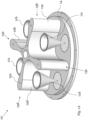
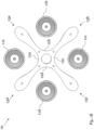
- antenna array 10 in the sense of the invention is illustrated in a three-dimensional view and a top view.
- said antenna array 10 exemplarily comprises four antennas with four reflectors 12a, 12b, 12c, 12d.
- every adjacent reflectors of the four reflectors 12a, 12b, 12c, 12d are connected with a double-tangential blended elliptical surface.
- the corresponding double-tangential blended elliptical surfaces are equipped with reference signs 13a, 13b, 13c, 13d.
- the antenna array 10 is used for direction finding.
- the four antennas are exemplarily arranged in a circular manner.
- each of the antennas comprises a monocone feed 11a, 11b, 11c, 11d especially for inputting an input signal and/or outputting an output signal, and the corresponding one of the above-mentioned four reflectors 12a, 12b, 12c, 12d or a corresponding reflecting surface, respectively, especially comprising a parabolic shape preferably for transmitting the input signal as an electromagnetic output wave and/or receiving an electromagnetic input wave as the output signal.
- an angle between two neighboring ones of said monocone feeds 11a, 11b, 11c, 11d is especially between 80 degrees and 100 degrees, preferably between 85 degrees and 95 degrees, more preferably between 88 degrees and 92 degrees, most preferably between 89.5 degrees and 90.5 degrees.
- parabolic shape may preferably be a two-dimensional parabolic shape.
- the reflectors 12a, 12b, 12c, 12d or reflecting surfaces, respectively are sandwiched between two planar surfaces.
- one of such planar surfaces is exemplarily illustrated in Fig. 1A and equipped with reference sign 14, wherein the corresponding other planar surface has been omitted to allow a detailed look inside the antenna array 10.
- said corresponding other planar surface would be substantially parallel to the planar surface 14.
- each of the above-mentioned monocone feeds 11a, 11b, 11c, 11d is located inside the corresponding cavity or the corresponding one of the four cavities, respectively.
- At least one, preferably each, of the monocone feeds 11a, 11b, 11c, 11d is placed at a focal line of the corresponding one of the reflectors 12a, 12b, 12c, 12d, or reflecting surfaces, respectively.
- the above-mentioned planar surfaces, wherein one of said planar surfaces is explicitly shown and equipped with reference sign 14, may especially be substantially perpendicular to said focal line.
- substantially perpendicular is especially to be understood as an angle between 80 degrees and 100 degrees, preferably between 85 degrees and 95 degrees, more preferably between 88 degrees and 92 degrees, most preferably between 89.5 degrees and 90.5 degrees.
- At least one, preferably each, of the monocone feeds 11a, 11b, 11c, 11d can be offset from a focal line, such as the above-mentioned focal line, and/or a focal point of the corresponding reflector or reflecting surface, respectively, such as the reflectors 12a, 12b, 12c, 12d.
- offset is especially to be understood as deviating from said focal line and/or said focal point of the corresponding reflector or reflecting surface, respectively, not more than 20 per cent, preferably 10 per cent, more preferably 5 per cent, most preferably 1 per cent, of the corresponding smallest or largest diameter of the monocone feed 11a.
- an antenna of the antenna array may especially be seen as a radiating element of the antenna. Accordingly, Fig. 1A or Fig. 1B , respectively, does also illustrate an exemplary embodiment of the inventive antenna.
- the double-tangential blended elliptical surface comprises or is a double-tangential blended elliptical reflector.
- said double-tangential blended elliptical surface may especially be configured to create a smooth surface.
- said smooth surface is configured such that there is no boundary between the at least two adjacent reflectors especially in order to avoid creating a Huygen's source or any kind thereof.
- the antenna array 10 or the antenna exemplarily comprises a reflective structure especially comprising the four reflectors 12a, 12b, 12c, 12d and the corresponding four double-tangential blended elliptical surfaces 13a, 13b, 13c, 13d.
- the basic shape of said reflective structure can substantially be a cross, preferably a cross without sharp edges.
- the outer edges of said cross are smoothened with the aid of corresponding double-tangential blended elliptical surfaces.
- a double-tangential blended elliptical surface in the sense of the invention may especially comprise a tangential blended elliptical edge such as the one according to Fig. 2A .
- the tangential blended elliptical edge comprises or is a tangential symmetric blended elliptical edge.
- the corresponding embodiment exemplarily comprises a first tangential blend 21, a second tangential blend 22, and a symmetric elliptical edge. Accordingly, it might be particularly advantageous if a tangential blended symmetric elliptical curve connects adjacent disposed reflectors, especially adjacent circularly disposed reflectors such as the reflectors 12a, 12b, 12c, 12d of Fig. 1A or Fig. 1B , respectively.
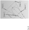
- a tangential blended elliptical edge or a tangential symmetric blended elliptical edge, respectively, such as the one of Fig 2A is formed on the basis of four poles.
- said poles may substantially form the corners of an imaginary trapezoid, preferably an imaginary symmetrical trapezoid.
- Fig. 3 shows a first exemplary electric field distribution 31 with respect to a first non-inventive antenna array in the sense of no blend regarding the corresponding reflectors.
- a second exemplary electric field distribution 32 with respect to a second non-inventive antenna array in the sense of a flat blend regarding the corresponding reflectors is depicted.
- both electric field distributions 31 and 32 apply for a frequency of 4 GHz.
- Fig. 4 shows an exemplary electric field distribution achieved by the invention, exemplarily by the antenna array 10 according to Fig. 1A or Fig. 1b , respectively.
- any Huygen's radiator is avoided.
- the electric field distribution of Fig. 4 exemplarily applies for a frequency of 4 GHz.
- Fig. 5 illustrates an exemplary comparison of non-inventive radiation patterns, such as ones being based on the non-inventive antenna arrays mentioned in the context of Fig. 3 above, with an inventive one such as one being based on the antenna array 10 according to Fig. 1A or Fig. 1B , respectively.
- Fig. 5 shows a first exemplary radiation pattern 51 with respect to a first non-inventive antenna array in the sense of no blend regarding the corresponding reflectors.
- a second exemplary radiation pattern 52 with respect to a second non-inventive antenna array in the sense of a flat blend regarding the corresponding reflectors is depicted.
- Fig. 5 shows a third exemplary radiation pattern 53 with respect to an inventive antenna array in the sense of a double-tangential blended elliptical surface regarding the corresponding reflectors.
- the corresponding radiated power in area 54 exemplarily marking a range between -5 degrees and 5 degrees, especially the corresponding boresight, is at least 3 dB higher than in areas 55a, 55b, exemplarily marking ranges between -100 degrees and -80 degrees and between 80 degrees and 100 degrees, especially at -90 degrees or 90 degrees, respectively.
- the invention exemplarily the antenna array 10 according to Fig. 1A or Fig. 1B , respectively, allows for a corresponding radiated power being significantly higher, exemplarily more than 10 dB higher, at 0 degrees than at -90 degrees or 90 degrees, respectively.
- the non-inventive radiation patterns 51 and 52 disadvantageously comprise a corresponding radiated power being higher at -90 degrees or 90 degrees, respectively, than at 0 degrees.
- each of the exemplary radiation patterns 51, 52, 53 exemplarily applies for a frequency of 4 GHz.
Landscapes
- Physics & Mathematics (AREA)
- Electromagnetism (AREA)
- Engineering & Computer Science (AREA)
- General Physics & Mathematics (AREA)
- Radar, Positioning & Navigation (AREA)
- Remote Sensing (AREA)
- Aerials With Secondary Devices (AREA)
Abstract
Description
- The invention relates to an antenna and an antenna array. In particular, the invention relates to an antenna and an antenna array for direction finding, especially wideband direction finding.
- Generally, in times of an increasing number of applications providing direction finding capabilities, there is a growing need of an antenna and an antenna array for being employed in the context of such applications in order to allow for direction finding in a particular accurate and efficient manner, thereby ensuring low space requirements and low costs.
- Document
US 5,270,726 A relates to a compact range system including a feed antenna offset from the rectangular-aperture paraboloidal reflector. The reflector has blended edges and smoothed corners to reduce contamination of propagated electromagnetic plane waves by diffracted energy. In accordance with said document, the continuous, smooth surface of the reflector should maximize the purity and uniformity of the plane waves from the reflector. Nevertheless, said document does not even recognize the problem that for wideband antennas with a cavity or reflector, respectively, behind the corresponding driving element, the edges of the reflector act as radiating sources. Disadvantageously, this results in strong sidelobes at +-90 degrees from the boresight or main direction, respectively, thereby not allowing for an accurate and efficient direction finding. - Accordingly, there is the object to provide an antenna and an antenna array especially allowing for direction finding in a particular accurate and efficient manner, thereby ensuring low space requirements and low costs.
- This object is solved by the features of the first independent claim for an antenna and the features of the second independent claim for an antenna array. The dependent claims contain further developments.
- According to a first aspect of the invention, an antenna is provided. Said antenna comprises at least two radiating elements with at least two reflectors offset from the at least two radiating elements. In this context, at least two adjacent reflectors of the at least two reflectors are connected with a double-tangential blended elliptical surface. Advantageously, this allows for direction finding in a particular accurate and efficient manner, thereby ensuring low space requirements and low costs. Further advantageously, the antenna can be a Compact Antenna Test Range (CATR) antenna especially such that the CATR antenna or a dual CATR system, respectively, can be milled from a single metal block.
- According to a first preferred implementation form of the first aspect of the invention, the double-tangential blended elliptical surface comprises or is a double-tangential blended elliptical reflector. Additionally or alternatively, the antenna is used for direction finding, especially wideband direction finding. Advantageously, for instance, re-radiating edges can be avoided, thereby increasing accuracy.
- According to a second preferred implementation form of the first aspect of the invention, the double-tangential blended elliptical surface is configured to create a smooth surface. Advantageously, for example, the transition between the corresponding reflector and the elliptical curve appears completely smooth for all frequencies of interest.
- According to a further preferred implementation form of the first aspect of the invention, the smooth surface is configured such that there is no boundary between the at least two adjacent reflectors especially in order to avoid creating a Huygen's source or any kind thereof. Advantageously, for instance, re-radiated energy can efficiently be prevented.
- According to a further preferred implementation form of the first aspect of the invention, the at least two radiating elements are four radiating elements, preferably four wideband radiating elements. In addition to this or as an alternative, the at least two reflectors are four reflectors. Further additionally or further alternatively, the antenna comprises four double-tangential blended elliptical surfaces. Advantageously, for example, especially in the context of a directional antenna with four cardinal directions, sidelobes at -90 degrees or 90 degrees, respectively, from the main direction can efficiently be suppressed.
- According to a further preferred implementation form of the first aspect of the invention, the at least two reflectors are arranged in a circular manner. Advantageously, for instance, complexity can be reduced, which leads to an increased efficiency.
- According to a further preferred implementation form of the first aspect of the invention, at least one, preferably each, of the at least two reflectors comprises or is of a parabolic shape. Advantageously, for example, the antenna can efficiently be adapted to the space requirements of the corresponding application in a flexible manner, which analogously applies for the following further preferred implementation forms of the first aspect of the invention.
- According to a further preferred implementation form of the first aspect of the invention, at least one, preferably each, of the at least two reflectors comprises or is of a circular shape.
- According to a further preferred implementation form of the first aspect of the invention, at least one, preferably each, of the at least two reflectors comprises or is of a flat, especially square, shape.
- According to a further preferred implementation form of the first aspect of the invention, at least one, preferably each, of the at least two reflectors comprises or is of a ellipsoidal shape.
- According to a further preferred implementation form of the first aspect of the invention, at least one, preferably each, of the at least two reflectors comprises or is of a hyperbolic shape.
- According to a second aspect of the invention, an antenna array is provided. Said antenna array comprises at least two antennas with at least two reflectors. In this context, at least two adjacent reflectors of the at least two reflectors are connected with a double-tangential blended elliptical surface. Advantageously, this allows for direction finding in a particular accurate and efficient manner, thereby ensuring low space requirements and low costs. Further advantageously, the antenna array can be a Compact Antenna Test Range (CATR) antenna array especially such that the CATR antenna array or a dual CATR system, respectively, can be milled from a single metal block.
- According to a first preferred implementation form of the second aspect of the invention, at least one of the at least two antennas comprises or is an antenna according to the first aspect of the invention or any of its preferred implementation forms, respectively. Additionally or alternatively, the antenna array is used for direction finding, especially wideband direction finding. Advantageously, for instance, re-radiating edges can be avoided, thereby increasing accuracy.
- According to a second preferred implementation form of the second aspect of the invention, each of the at least two antennas comprises or is an antenna according to the first aspect of the invention or any of its preferred implementation forms, respectively. Advantageously, for example, both accuracy and efficiency can further be increased.
- According to a further preferred implementation form of the second aspect of the invention, the at least two antennas are four antennas, preferably four circularly arranged antennas. Advantageously, for instance, complexity can be reduced, which leads to an increased efficiency.
- According to a further preferred implementation form of the second aspect of the invention, the double-tangential blended elliptical surface comprises or is a double-tangential blended elliptical reflector. Advantageously, for example, re-radiating edges can be avoided, thereby increasing accuracy.
- According to a further preferred implementation form of the second aspect of the invention, the double-tangential blended elliptical surface is configured to create a smooth surface. Advantageously, for instance, the transition between the corresponding reflector and the elliptical curve appears completely smooth for all frequencies of interest.
- According to a further preferred implementation form of the second aspect of the invention, the smooth surface is configured such that there is no boundary between the at least two adjacent reflectors especially in order to avoid creating a Huygen's source or any kind thereof. Advantageously, for instance, re-radiated energy can efficiently be prevented.
- According to a further preferred implementation form of the second aspect of the invention, the at least two reflectors are four reflectors. Additionally or alternatively, the antenna array comprises four double-tangential blended elliptical surfaces. Advantageously, for example, especially in the context of a directional antenna array with four cardinal directions, sidelobes at -90 degrees or 90 degrees, respectively, from the main direction can efficiently be suppressed.
- According to a further preferred implementation form of the second aspect of the invention, at least one, preferably each, of the at least two reflectors comprises or is of a parabolic shape. Advantageously, for instance, the antenna array can efficiently be adapted to the space requirements of the corresponding application in a flexible manner, which analogously applies for the following further preferred implementation forms of the second aspect of the invention.
- According to a further preferred implementation form of the second aspect of the invention, at least one, preferably each, of the at least two reflectors comprises or is of a circular shape.
- According to a further preferred implementation form of the second aspect of the invention, at least one, preferably each, of the at least two reflectors comprises or is of a flat, especially square, shape.
- According to a further preferred implementation form of the second aspect of the invention, at least one, preferably each, of the at least two reflectors comprises or is of a ellipsoidal shape.
- According to a further preferred implementation form of the second aspect of the invention, at least one, preferably each, of the at least two reflectors comprises or is of a hyperbolic shape.
- Exemplary embodiments of the invention are now further explained with respect to the drawings by way of example only, and not for limitation. In the drawings:
- Fig. 1A
- shows an exemplary embodiment of an antenna array or an antenna, respectively, in the sense of the invention in a three-dimensional view;
- Fig. 1B
- shows a top view of the antenna array or antenna, respectively, of
Fig. 1A ; - Fig. 2A
- shows an exemplary embodiment of a tangential blended elliptical edge in the sense of the invention;
- Fig. 2B
- shows further details of a tangential blended elliptical edge such as the one of
Fig. 2A ; - Fig. 3
- shows two exemplary electric field distributions with respect to two non-inventive antenna arrays in the sense of no blend and a flat blend;
- Fig. 4
- shows an exemplary electric field distribution achieved by the invention; and
- Fig. 5
- shows an exemplary comparison of non-inventive radiation patterns with an inventive one.
- With respect to
Fig. 1A andFig. 1B , an exemplary embodiment ofantenna array 10 in the sense of the invention is illustrated in a three-dimensional view and a top view. - According to
Fig. 1 , saidantenna array 10 exemplarily comprises four antennas with fourreflectors reflectors reference signs - It is noted that it might be particularly advantageous if the
antenna array 10 is used for direction finding. - As it can further be seen from
Fig. 1A orFig. 1B , respectively, the four antennas are exemplarily arranged in a circular manner. - In this exemplary case, each of the antennas comprises a
monocone feed reflectors - It might be particularly advantageous if the monocone feeds
11a - With respect to the above-mentioned parabolic shape, it is noted that said parabolic shape may preferably be a two-dimensional parabolic shape.
- It is further noted that it might be particularly advantageous if the
reflectors Fig. 1A and equipped withreference sign 14, wherein the corresponding other planar surface has been omitted to allow a detailed look inside theantenna array 10. Preferably, said corresponding other planar surface would be substantially parallel to theplanar surface 14. - It might be particularly advantageous if the
respective reflectors monocone feeds - Furthermore, it might be particularly advantageous if at least one, preferably each, of the monocone feeds 11a, 11b, 11c, 11d is placed at a focal line of the corresponding one of the
reflectors reference sign 14, may especially be substantially perpendicular to said focal line. - It is further noted that the term "substantially perpendicular" is especially to be understood as an angle between 80 degrees and 100 degrees, preferably between 85 degrees and 95 degrees, more preferably between 88 degrees and 92 degrees, most preferably between 89.5 degrees and 90.5 degrees.
- Moreover, especially as an alternative, at least one, preferably each, of the monocone feeds 11a, 11b, 11c, 11d can be offset from a focal line, such as the above-mentioned focal line, and/or a focal point of the corresponding reflector or reflecting surface, respectively, such as the
reflectors - In this context, the term "offset" is especially to be understood as deviating from said focal line and/or said focal point of the corresponding reflector or reflecting surface, respectively, not more than 20 per cent, preferably 10 per cent, more preferably 5 per cent, most preferably 1 per cent, of the corresponding smallest or largest diameter of the
monocone feed 11a. - With respect to the above-mentioned two planar surfaces, it is noted that it might be particularly advantageous if said two planar surfaces are of circular shape and/or of the same size.
- Moreover, especially for the sake of completeness, it is noted that both all the explanations above and all the explanations below may analogously apply for an inventive antenna and vice versa. In this context, an antenna of the antenna array may especially be seen as a radiating element of the antenna. Accordingly,
Fig. 1A orFig. 1B , respectively, does also illustrate an exemplary embodiment of the inventive antenna. - With respect to the above-mentioned double-tangential blended elliptical surface, it is noted that it might be particularly advantageous if the double-tangential blended elliptical surface comprises or is a double-tangential blended elliptical reflector.
- Furthermore, said double-tangential blended elliptical surface may especially be configured to create a smooth surface.
- It might be particularly advantageous if said smooth surface is configured such that there is no boundary between the at least two adjacent reflectors especially in order to avoid creating a Huygen's source or any kind thereof.
- As it can further be seen from
Fig. 1B , theantenna array 10 or the antenna, respectively, exemplarily comprises a reflective structure especially comprising the fourreflectors elliptical surfaces - Now, with respect to
Fig. 2A , an exemplary embodiment of a tangential blended elliptical edge in the sense of the invention is depicted. Said embodiment may especially be seen as a magnification of one of the double-tangential blendedelliptical surfaces Fig. 1A orFig. 1B , respectively. Accordingly, a double-tangential blended elliptical surface in the sense of the invention may especially comprise a tangential blended elliptical edge such as the one according toFig. 2A . - With respect to said tangential blended elliptical edge, it is noted that it might be particularly advantageous if the tangential blended elliptical edge comprises or is a tangential symmetric blended elliptical edge.
- In accordance with
Fig. 2A , the corresponding embodiment exemplarily comprises a firsttangential blend 21, a secondtangential blend 22, and a symmetric elliptical edge. Accordingly, it might be particularly advantageous if a tangential blended symmetric elliptical curve connects adjacent disposed reflectors, especially adjacent circularly disposed reflectors such as thereflectors Fig. 1A orFig. 1B , respectively. - In the light of
Fig. 2B , it is noted that it might be particularly advantageous if a tangential blended elliptical edge or a tangential symmetric blended elliptical edge, respectively, such as the one ofFig 2A , is formed on the basis of four poles. In this context, said poles may substantially form the corners of an imaginary trapezoid, preferably an imaginary symmetrical trapezoid. - Furthermore,
Fig. 3 shows a first exemplaryelectric field distribution 31 with respect to a first non-inventive antenna array in the sense of no blend regarding the corresponding reflectors. - In addition to this, a second exemplary
electric field distribution 32 with respect to a second non-inventive antenna array in the sense of a flat blend regarding the corresponding reflectors is depicted. - As it can be seen in accordance with
reference sign 33 ofFig. 3 , in both cases, the no blend or flat blend areas, respectively, disadvantageously lead to a respective Huygen's radiator which re-radiates energy. - For the sake of completeness, it is noted that both
electric field distributions - Moreover,
Fig. 4 shows an exemplary electric field distribution achieved by the invention, exemplarily by theantenna array 10 according toFig. 1A orFig. 1b , respectively. Advantageously, due to the inventive configuration, any Huygen's radiator is avoided. It is noted that the electric field distribution ofFig. 4 exemplarily applies for a frequency of 4 GHz. - Finally,
Fig. 5 illustrates an exemplary comparison of non-inventive radiation patterns, such as ones being based on the non-inventive antenna arrays mentioned in the context ofFig. 3 above, with an inventive one such as one being based on theantenna array 10 according toFig. 1A orFig. 1B , respectively. -
Fig. 5 shows a firstexemplary radiation pattern 51 with respect to a first non-inventive antenna array in the sense of no blend regarding the corresponding reflectors. - In addition to this, a second
exemplary radiation pattern 52 with respect to a second non-inventive antenna array in the sense of a flat blend regarding the corresponding reflectors is depicted. - Further additionally,
Fig. 5 shows a thirdexemplary radiation pattern 53 with respect to an inventive antenna array in the sense of a double-tangential blended elliptical surface regarding the corresponding reflectors. - It is noted that it might be particularly advantageous if the corresponding radiated power in
area 54, exemplarily marking a range between -5 degrees and 5 degrees, especially the corresponding boresight, is at least 3 dB higher than inareas - In accordance with
reference sign 56 ofFig. 5 , the invention, exemplarily theantenna array 10 according toFig. 1A orFig. 1B , respectively, allows for a corresponding radiated power being significantly higher, exemplarily more than 10 dB higher, at 0 degrees than at -90 degrees or 90 degrees, respectively. - In addition to this, as it can further be seen from
Fig. 5 , it is noted that thenon-inventive radiation patterns - For the sake of completeness, it is further noted that each of the
exemplary radiation patterns - While various embodiments of the present invention have been described above, it should be understood that they have been presented by way of example only, and not limitation. Numerous changes to the disclosed embodiments can be made in accordance with the disclosure herein without departing from the spirit or scope of the invention. Thus, the breadth and scope of the present invention should not be limited by any of the above described embodiments. Rather, the scope of the invention should be defined in accordance with the following claims and their equivalents.
- Although the invention has been illustrated and described with respect to one or more implementations, equivalent alterations and modifications will occur to others skilled in the art upon the reading and understanding of this specification and the annexed drawings. In addition, while a particular feature of the invention may have been disclosed with respect to only one of several implementations, such feature may be combined with one or more other features of the other implementations as may be desired and advantageous for any given or particular application.
Claims (15)
- An antenna comprising:
at least two radiating elements with at least two reflectors (12a, 12b, 12c, 12d) offset from the at least two radiating elements,
wherein at least two adjacent reflectors of the at least two reflectors (12a, 12b, 12c, 12d) are connected with a double-tangential blended elliptical surface (13a, 13b, 13c, 13d). - The antenna according to claim 1,wherein the double-tangential blended elliptical surface (13a, 13b, 13c, 13d) comprises or is a double-tangential blended elliptical reflector, and/orwherein the antenna is used for direction finding.
- The antenna according to claim 1 or 2,
wherein the double-tangential blended elliptical surface (13a, 13b, 13c, 13d) is configured to create a smooth surface. - The antenna according to claim 3,
wherein the smooth surface is configured such that there is no boundary between the at least two adjacent reflectors especially in order to avoid creating a Huygen's source or any kind thereof. - The antenna according to any of the claims 1 to 4,wherein the at least two radiating elements are four radiating elements, preferably four wideband radiating elements, and/orwherein the at least two reflectors (12a, 12b, 12c, 12d) are four reflectors, and/orwherein the antenna comprises four double-tangential blended elliptical surfaces (13a, 13b, 13c, 13d).
- The antenna according to any of the claims 1 to 5, wherein the at least two reflectors (12a, 12b, 12c, 12d) are arranged in a circular manner.
- The antenna according to any of the claims 1 to 6, wherein at least one, preferably each, of the at least two reflectors (12a, 12b, 12c, 12d) comprises or is of a parabolic shape.
- The antenna according to any of the claims 1 to 7, wherein at least one, preferably each, of the at least two reflectors (12a, 12b, 12c, 12d) comprises or is of a circular shape.
- The antenna according to any of the claims 1 to 8, wherein at least one, preferably each, of the at least two reflectors (12a, 12b, 12c, 12d) comprises or is of a flat, especially square, shape.
- The antenna according to any of the claims 1 to 9, wherein at least one, preferably each, of the at least two reflectors (12a, 12b, 12c, 12d) comprises or is of a ellipsoidal shape.
- The antenna according to any of the claims 1 to 10, wherein at least one, preferably each, of the at least two reflectors (12a, 12b, 12c, 12d) comprises or is of a hyperbolic shape.
- An antenna array (10) comprising:
at least two antennas with at least two reflectors (12a, 12b, 12c, 12d),
wherein at least two adjacent reflectors of the at least two reflectors (12a, 12b, 12c, 12d) are connected with a double-tangential blended elliptical surface (13a, 13b, 13c, 13d). - The antenna array (10) according to claim 12,wherein at least one of the at least two antennas comprises or is an antenna according to any of the claims 1 to 11, and/orwherein the antenna array (10) is used for direction finding.
- The antenna array (10) according to claim 12,
wherein each of the at least two antennas comprises or is an antenna according to any of the claims 1 to 11. - The antenna array (10) according to any of the claims 12 to 14,
wherein the at least two antennas are four antennas, preferably four circularly arranged antennas.
Priority Applications (3)
| Application Number | Priority Date | Filing Date | Title |
|---|---|---|---|
| EP23157528.3A EP4418461A1 (en) | 2023-02-20 | 2023-02-20 | Antenna and antenna array |
| CN202410030402.XA CN118523092A (en) | 2023-02-20 | 2024-01-09 | Antennas and Antenna Arrays |
| US18/409,460 US20240283162A1 (en) | 2023-02-20 | 2024-01-10 | Antenna and antenna array |
Applications Claiming Priority (1)
| Application Number | Priority Date | Filing Date | Title |
|---|---|---|---|
| EP23157528.3A EP4418461A1 (en) | 2023-02-20 | 2023-02-20 | Antenna and antenna array |
Publications (1)
| Publication Number | Publication Date |
|---|---|
| EP4418461A1 true EP4418461A1 (en) | 2024-08-21 |
Family
ID=85285135
Family Applications (1)
| Application Number | Title | Priority Date | Filing Date |
|---|---|---|---|
| EP23157528.3A Pending EP4418461A1 (en) | 2023-02-20 | 2023-02-20 | Antenna and antenna array |
Country Status (3)
| Country | Link |
|---|---|
| US (1) | US20240283162A1 (en) |
| EP (1) | EP4418461A1 (en) |
| CN (1) | CN118523092A (en) |
Families Citing this family (1)
| Publication number | Priority date | Publication date | Assignee | Title |
|---|---|---|---|---|
| EP4358296B1 (en) * | 2022-10-20 | 2025-12-03 | Rohde & Schwarz GmbH & Co. KG | Antenna and antenna system |
Citations (4)
| Publication number | Priority date | Publication date | Assignee | Title |
|---|---|---|---|---|
| US5270726A (en) | 1990-08-06 | 1993-12-14 | The Boeing Company | Rectangular aperture reflector for radar cross section and antenna pattern compact ranges |
| US20160359237A1 (en) * | 2014-02-08 | 2016-12-08 | Smart Antenna Systems, Inc. | Wideband antenna star array |
| US10050752B1 (en) * | 2015-02-06 | 2018-08-14 | Sprint Communications Company L.P. | Radial antenna for small cell with a null feature |
| WO2022180378A1 (en) * | 2021-02-23 | 2022-09-01 | Oxford Rf Solutions Ltd | Multi-directional transducer system |
Family Cites Families (4)
| Publication number | Priority date | Publication date | Assignee | Title |
|---|---|---|---|---|
| US20030184490A1 (en) * | 2002-03-26 | 2003-10-02 | Raiman Clifford E. | Sectorized omnidirectional antenna |
| RU2380802C1 (en) * | 2008-11-17 | 2010-01-27 | Джи-хо Ан | Compact multibeam mirror antenna |
| US10476611B2 (en) * | 2017-12-29 | 2019-11-12 | Rohde & Schwarz Gmbh & Co. Kg | Compact antenna range reflector with reduced edge diffraction |
| US10892544B2 (en) * | 2018-01-15 | 2021-01-12 | Rogers Corporation | Dielectric resonator antenna having first and second dielectric portions |
-
2023
- 2023-02-20 EP EP23157528.3A patent/EP4418461A1/en active Pending
-
2024
- 2024-01-09 CN CN202410030402.XA patent/CN118523092A/en active Pending
- 2024-01-10 US US18/409,460 patent/US20240283162A1/en active Pending
Patent Citations (4)
| Publication number | Priority date | Publication date | Assignee | Title |
|---|---|---|---|---|
| US5270726A (en) | 1990-08-06 | 1993-12-14 | The Boeing Company | Rectangular aperture reflector for radar cross section and antenna pattern compact ranges |
| US20160359237A1 (en) * | 2014-02-08 | 2016-12-08 | Smart Antenna Systems, Inc. | Wideband antenna star array |
| US10050752B1 (en) * | 2015-02-06 | 2018-08-14 | Sprint Communications Company L.P. | Radial antenna for small cell with a null feature |
| WO2022180378A1 (en) * | 2021-02-23 | 2022-09-01 | Oxford Rf Solutions Ltd | Multi-directional transducer system |
Also Published As
| Publication number | Publication date |
|---|---|
| CN118523092A (en) | 2024-08-20 |
| US20240283162A1 (en) | 2024-08-22 |
Similar Documents
| Publication | Publication Date | Title |
|---|---|---|
| CN111916909B (en) | Low-profile circularly polarized vortex wave folded transmission array antenna based on super surface | |
| US20050140559A1 (en) | Hexagonal array structure of dielectric rod to shape flat-topped element pattern | |
| KR100944216B1 (en) | Compact multi beam reflector antenna | |
| US6919854B2 (en) | Variable inclination continuous transverse stub array | |
| US11482790B2 (en) | Dielectric lens and electromagnetic device with same | |
| US9413073B2 (en) | Augmented E-plane taper techniques in variable inclination continuous transverse (VICTS) antennas | |
| CN110165403A (en) | Hemisphere dielectric lens antenna is deformed based on array-fed large-angle scanning | |
| US20240283162A1 (en) | Antenna and antenna array | |
| WO2019170541A1 (en) | Extreme scanning focal-plane arrays using a double-reflector concept with uniform array illumination | |
| JP6337171B1 (en) | Antenna device | |
| JP5054174B2 (en) | antenna | |
| US20100039338A1 (en) | Planar Scanner Antenna for High Frequency Scanning and Radar Environments | |
| KR102279931B1 (en) | Planar linear phase array antenna with enhanced beam scanning | |
| EP4358296B1 (en) | Antenna and antenna system | |
| Reutov et al. | Focuser-based hybrid antennas for one-dimensional beam steering | |
| US10797401B2 (en) | Reflection mirror antenna device | |
| RU2278453C1 (en) | Radar antenna of reduced effective dissipation area | |
| JPS5915204B2 (en) | Constant beam width antenna | |
| US12034210B2 (en) | Leaky wave antenna | |
| JP2003158420A (en) | Dielectric leaky wave antenna | |
| KR102724494B1 (en) | Transmitarray antenna for simultaneous beam forming and focusing | |
| RU2754192C1 (en) | Hybrid mirror antenna | |
| KR100802895B1 (en) | Thin antenna | |
| RU2514128C2 (en) | Mirror-horn antenna | |
| Bobkov | General Principles for Constructing Frequency-Independent Antennas |
Legal Events
| Date | Code | Title | Description |
|---|---|---|---|
| PUAI | Public reference made under article 153(3) epc to a published international application that has entered the european phase |
Free format text: ORIGINAL CODE: 0009012 |
|
| STAA | Information on the status of an ep patent application or granted ep patent |
Free format text: STATUS: THE APPLICATION HAS BEEN PUBLISHED |
|
| STAA | Information on the status of an ep patent application or granted ep patent |
Free format text: STATUS: REQUEST FOR EXAMINATION WAS MADE |
|
| AK | Designated contracting states |
Kind code of ref document: A1 Designated state(s): AL AT BE BG CH CY CZ DE DK EE ES FI FR GB GR HR HU IE IS IT LI LT LU LV MC ME MK MT NL NO PL PT RO RS SE SI SK SM TR |
|
| 17P | Request for examination filed |
Effective date: 20240806 |
|
| RBV | Designated contracting states (corrected) |
Designated state(s): AL AT BE BG CH CY CZ DE DK EE ES FI FR GB GR HR HU IE IS IT LI LT LU LV MC ME MK MT NL NO PL PT RO RS SE SI SK SM TR |
|
| GRAP | Despatch of communication of intention to grant a patent |
Free format text: ORIGINAL CODE: EPIDOSNIGR1 |
|
| STAA | Information on the status of an ep patent application or granted ep patent |
Free format text: STATUS: GRANT OF PATENT IS INTENDED |
|
| RIC1 | Information provided on ipc code assigned before grant |
Ipc: H01Q 15/16 20060101AFI20260708BHEP Ipc: H01Q 9/40 20060101ALI20260708BHEP Ipc: H01Q 21/20 20060101ALI20260708BHEP |