EP4418420A1 - Battery pack having improved fixation strength of accommodated battery module and device including same - Google Patents
Battery pack having improved fixation strength of accommodated battery module and device including same Download PDFInfo
- Publication number
- EP4418420A1 EP4418420A1 EP23880132.8A EP23880132A EP4418420A1 EP 4418420 A1 EP4418420 A1 EP 4418420A1 EP 23880132 A EP23880132 A EP 23880132A EP 4418420 A1 EP4418420 A1 EP 4418420A1
- Authority
- EP
- European Patent Office
- Prior art keywords
- extension portion
- battery module
- battery
- pack case
- receiving portion
- Prior art date
- Legal status (The legal status is an assumption and is not a legal conclusion. Google has not performed a legal analysis and makes no representation as to the accuracy of the status listed.)
- Pending
Links
Images




Classifications
-
- H—ELECTRICITY
- H01—ELECTRIC ELEMENTS
- H01M—PROCESSES OR MEANS, e.g. BATTERIES, FOR THE DIRECT CONVERSION OF CHEMICAL ENERGY INTO ELECTRICAL ENERGY
- H01M50/00—Constructional details or processes of manufacture of the non-active parts of electrochemical cells other than fuel cells, e.g. hybrid cells
- H01M50/20—Mountings; Secondary casings or frames; Racks, modules or packs; Suspension devices; Shock absorbers; Transport or carrying devices; Holders
- H01M50/233—Mountings; Secondary casings or frames; Racks, modules or packs; Suspension devices; Shock absorbers; Transport or carrying devices; Holders characterised by physical properties of casings or racks, e.g. dimensions
- H01M50/242—Mountings; Secondary casings or frames; Racks, modules or packs; Suspension devices; Shock absorbers; Transport or carrying devices; Holders characterised by physical properties of casings or racks, e.g. dimensions adapted for protecting batteries against vibrations, collision impact or swelling
-
- H—ELECTRICITY
- H01—ELECTRIC ELEMENTS
- H01M—PROCESSES OR MEANS, e.g. BATTERIES, FOR THE DIRECT CONVERSION OF CHEMICAL ENERGY INTO ELECTRICAL ENERGY
- H01M50/00—Constructional details or processes of manufacture of the non-active parts of electrochemical cells other than fuel cells, e.g. hybrid cells
- H01M50/20—Mountings; Secondary casings or frames; Racks, modules or packs; Suspension devices; Shock absorbers; Transport or carrying devices; Holders
- H01M50/262—Mountings; Secondary casings or frames; Racks, modules or packs; Suspension devices; Shock absorbers; Transport or carrying devices; Holders with fastening means, e.g. locks
- H01M50/264—Mountings; Secondary casings or frames; Racks, modules or packs; Suspension devices; Shock absorbers; Transport or carrying devices; Holders with fastening means, e.g. locks for cells or batteries, e.g. straps, tie rods or peripheral frames
-
- H—ELECTRICITY
- H01—ELECTRIC ELEMENTS
- H01M—PROCESSES OR MEANS, e.g. BATTERIES, FOR THE DIRECT CONVERSION OF CHEMICAL ENERGY INTO ELECTRICAL ENERGY
- H01M50/00—Constructional details or processes of manufacture of the non-active parts of electrochemical cells other than fuel cells, e.g. hybrid cells
- H01M50/20—Mountings; Secondary casings or frames; Racks, modules or packs; Suspension devices; Shock absorbers; Transport or carrying devices; Holders
- H01M50/204—Racks, modules or packs for multiple batteries or multiple cells
-
- H—ELECTRICITY
- H01—ELECTRIC ELEMENTS
- H01M—PROCESSES OR MEANS, e.g. BATTERIES, FOR THE DIRECT CONVERSION OF CHEMICAL ENERGY INTO ELECTRICAL ENERGY
- H01M50/00—Constructional details or processes of manufacture of the non-active parts of electrochemical cells other than fuel cells, e.g. hybrid cells
- H01M50/20—Mountings; Secondary casings or frames; Racks, modules or packs; Suspension devices; Shock absorbers; Transport or carrying devices; Holders
- H01M50/244—Secondary casings; Racks; Suspension devices; Carrying devices; Holders characterised by their mounting method
-
- H—ELECTRICITY
- H01—ELECTRIC ELEMENTS
- H01M—PROCESSES OR MEANS, e.g. BATTERIES, FOR THE DIRECT CONVERSION OF CHEMICAL ENERGY INTO ELECTRICAL ENERGY
- H01M50/00—Constructional details or processes of manufacture of the non-active parts of electrochemical cells other than fuel cells, e.g. hybrid cells
- H01M50/20—Mountings; Secondary casings or frames; Racks, modules or packs; Suspension devices; Shock absorbers; Transport or carrying devices; Holders
- H01M50/262—Mountings; Secondary casings or frames; Racks, modules or packs; Suspension devices; Shock absorbers; Transport or carrying devices; Holders with fastening means, e.g. locks
-
- H—ELECTRICITY
- H01—ELECTRIC ELEMENTS
- H01M—PROCESSES OR MEANS, e.g. BATTERIES, FOR THE DIRECT CONVERSION OF CHEMICAL ENERGY INTO ELECTRICAL ENERGY
- H01M2220/00—Batteries for particular applications
- H01M2220/20—Batteries in motive systems, e.g. vehicle, ship, plane
-
- H—ELECTRICITY
- H01—ELECTRIC ELEMENTS
- H01M—PROCESSES OR MEANS, e.g. BATTERIES, FOR THE DIRECT CONVERSION OF CHEMICAL ENERGY INTO ELECTRICAL ENERGY
- H01M50/00—Constructional details or processes of manufacture of the non-active parts of electrochemical cells other than fuel cells, e.g. hybrid cells
- H01M50/20—Mountings; Secondary casings or frames; Racks, modules or packs; Suspension devices; Shock absorbers; Transport or carrying devices; Holders
- H01M50/289—Mountings; Secondary casings or frames; Racks, modules or packs; Suspension devices; Shock absorbers; Transport or carrying devices; Holders characterised by spacing elements or positioning means within frames, racks or packs
- H01M50/291—Mountings; Secondary casings or frames; Racks, modules or packs; Suspension devices; Shock absorbers; Transport or carrying devices; Holders characterised by spacing elements or positioning means within frames, racks or packs characterised by their shape
-
- Y—GENERAL TAGGING OF NEW TECHNOLOGICAL DEVELOPMENTS; GENERAL TAGGING OF CROSS-SECTIONAL TECHNOLOGIES SPANNING OVER SEVERAL SECTIONS OF THE IPC; TECHNICAL SUBJECTS COVERED BY FORMER USPC CROSS-REFERENCE ART COLLECTIONS [XRACs] AND DIGESTS
- Y02—TECHNOLOGIES OR APPLICATIONS FOR MITIGATION OR ADAPTATION AGAINST CLIMATE CHANGE
- Y02E—REDUCTION OF GREENHOUSE GAS [GHG] EMISSIONS, RELATED TO ENERGY GENERATION, TRANSMISSION OR DISTRIBUTION
- Y02E60/00—Enabling technologies; Technologies with a potential or indirect contribution to GHG emissions mitigation
- Y02E60/10—Energy storage using batteries
Definitions
- the present invention relates to a battery pack with increased fixation force of a battery module received therein and a device including the same, and more particularly to a battery pack with increased fixation force of a battery module received therein configured such that fixation force of a battery module received in a pack case is increased, whereby movement of the battery module is inhibited, and therefore stability of the battery module is improved, and a device including the same.
- Secondary batteries which are capable of being charged and discharged, are intimately used in daily life.
- secondary batteries are used in mobile devices, electric vehicles, and hybrid electric vehicles.
- the battery pack may be formed to have a long length, and such a battery pack may require an appropriate distance between a battery module and the battery pack when the battery module is received in order to facilitate assembly.
- FIG. 1 is a sectional view showing a part of a conventional battery pack.
- the conventional battery pack may include a cell assembly 10, a pack housing 20 configured to receive the cell assembly 10, an outer protrusion 30 formed on an outer surface of the cell assembly 10, and an inner protrusion 40 formed on an inner surface of the pack housing 20.
- the outer protrusion 30 and the inner protrusion 40 are formed to fill the distance between the cell assembly 10 and the pack housing 20, thereby increasing fixation force of the cell assembly 10.
- each of the outer protrusion 30 and the inner protrusion 40 is equal to or greater than the distance between the cell assembly 10 and the pack housing 20, whereby it may not be easy to insert the cell assembly 10 into the pack housing 20, and the cell assembly may be damaged by friction generated during insertion.
- Patent Document 1 Korean Patent Application Publication No. 2015-0062800
- the present invention has been made in view of the above problems, and it is an object of the present invention to provide a battery pack with increased fixation force of a battery module received therein configured such that fixation force of a battery module received in a pack case of the battery pack is increased, whereby movement of the battery module is inhibited, and a device including the same.
- a battery pack with increased fixation force of a battery module received therein includes a battery module (100) accommodating a plurality of battery cells therein, a lower pack case (200) having a receiving space configured to receive the battery module (100) therein, and an upper pack case (300) located at one surface of the lower pack case (200), wherein a first extension portion (110) is formed at an outer surface of the battery module (100) and extends parallel to the outer surface of the battery module (100) by a predetermined length, wherein the first extension portion being spaced apart from the outer surface of the battery module, and wherein a second extension portion (210) is formed at an inner surface of the lower pack case (200) or the upper pack case (300) and extends in a direction toward the first extension portion (110).
- the lower pack case (200) or the upper pack case (300) may include a second receiving portion (220) extending parallel to the second extension portion (210), the second receiving portion being recessed by a predetermined depth.
- the battery module (100) may include a first receiving portion (120) disposed on the outer surface of the battery module and is adjacent to the first extension portion (110), wherein the first receiving portion (120) is recessed by a predetermined depth.
- each of the second extension portion (210) and the second receiving portion (220) may extend from an edge of an inner bottom surface of the lower pack case (200).
- each of the first extension portion (110), the first receiving portion (120), the second extension portion (210), and the second receiving portion (220) may be located so as not to overlap each other on a vertical extension line.
- the first extension portion (110) may have a first protrusion (111) protruding from an end of a surface of the first extension portion (110) facing the battery module (100) .
- the second extension portion (210) may include an incision portion (211) formed as a result of some area being cut.
- the first extension portion (110) and the second extension portion (210) may be formed respectively on surfaces of the battery module (100) and the lower pack case (200) adjacent to each other in one or more.
- each of the first extension portion (110) and the second extension portion (210) may include an elastic material.
- the sum of a thickness of the first extension portion (110), a thickness of the second extension portion (210), and a thickness of the second receiving portion (220) may be equal to or greater than the distance between the battery module (100) and the lower pack case (200).
- the first extension portion (110) may be configured to be inserted between the second extension portion (210) and the second receiving portion (220), and the second receiving portion (220) may be configured to be inserted between the first extension portion (110) and the first receiving portion (120), whereby fixing therebetween may be achieved by fitting.
- the second extension portion may be spaced apart from the inner surface of the lower pack case before the first extension portion is fixed by fitting.
- the present invention provides a device having the battery pack having the aforementioned features mounted therein.
- a battery pack with increased fixation force of a battery module received therein has an advantage in that a first extension portion is made of an elastic material, whereby it is possible to relatively easily insert and receive a battery module into and in a pack case.
- the battery pack according to the present invention has an advantage in that the first extension portion, a second extension portion, and a second receiving portion are inserted between each other and fixed by fitting, whereby it is possible to inhibit movement of the battery module.
- FIG. 2 is a perspective view showing a battery pack according to a first preferred embodiment of the present invention from which an upper pack case is separated
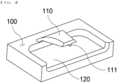
- FIG. 3 is an enlarged perspective view showing a first extension portion and a first receiving portion in the battery pack according to the first preferred embodiment of the present invention
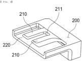
- FIG. 4 is an enlarged perspective view showing a second extension portion and a second receiving portion in a lower pack case according to a first preferred embodiment of the present invention
- FIG. 5 is a sectional view showing coupling between a first extension portion, a second extension portion, and a second receiving portion according to a first preferred embodiment of the present invention.
- the battery pack according to the present invention may include a battery module 100, a lower pack case 200, and an upper pack case 300.
- a plurality of battery cells may be received in the battery module 100, and at least one first extension portion 110 and a first receiving portion 120 may be formed at an outer surface of the battery module 100.
- the battery cell includes a cell case, an electrode assembly received in the cell case, a pair of electrode tabs, a pair of electrode leads constituted by a positive electrode lead and a negative electrode lead, each of which has one side electrically connected to a corresponding one of the electrode tabs and the other side protruding out of the cell case, and an insulating film.
- a receiving portion configured to receive the electrode assembly is formed in the cell case using a laminate sheet constituted by an outer covering layer, a metal layer, and an inner covering layer.
- the inner covering layer is disposed in direct contact with the electrode assembly, and therefore the inner covering layer must exhibit high insulation properties and high electrolytic resistance.
- the inner covering layer must exhibit high sealability in order to hermetically isolate the cell case from the outside, i.e., a thermally-bonded sealed portion between inner layers must exhibit excellent thermal bonding strength.
- the inner covering layer may be made of a material selected from among a polyolefin-based resin, such as polypropylene, polyethylene, polyethylene acrylic acid, or polybutylene, a polyurethane resin, and a polyimide resin, which exhibit excellent chemical resistance and high sealability; however, the present invention is not limited thereto, and polypropylene, which exhibits excellent mechanical properties, such as tensile strength, rigidity, surface hardness, and impact resistance, and excellent chemical resistance, is the most preferably used.
- a polyolefin-based resin such as polypropylene, polyethylene, polyethylene acrylic acid, or polybutylene, a polyurethane resin, and a polyimide resin, which exhibit excellent chemical resistance and high sealability
- polypropylene which exhibits excellent mechanical properties, such as tensile strength, rigidity, surface hardness, and impact resistance, and excellent chemical resistance, is the most preferably used.
- the metal layer which abuts the inner covering layer, corresponds to a barrier layer configured to prevent moisture or various kinds of gas from permeating into the battery from the outside.
- An aluminum thin film which is lightweight and easily shapeable, may be used as a preferred material for the metal layer.
- the outer covering layer is located at the other surface of the metal layer, and the outer covering layer may be made of a heat-resistant polymer that exhibits excellent tensile strength, resistance to moisture permeation, and resistance to air transmission such that the outer covering layer exhibits high heat resistance and chemical resistance while protecting the electrode assembly.
- the outer resin layer may be made of nylon or polyethylene terephthalate; however, the present invention is not limited thereto.
- the electrode assembly which is received in the cell case, may be a jelly-roll type electrode assembly, which is configured to have a structure in which a long sheet type negative electrode and a long sheet type positive electrode are wound in the state in which a separator is interposed therebetween, a stacked type electrode assembly including unit cells, each of which is configured to have a structure in which a rectangular positive electrode and a rectangular negative electrode are stacked in the state in which a separator is interposed therebetween, a stacked and folded type electrode assembly, which is configured to have a structure in which unit cells are wound using a long separation film, or a laminated and stacked type electrode assembly, which is configured to have a structure in which unit cells are stacked in the state in which a separator is interposed therebetween and are then attached to each other; however, the present invention is not limited thereto.
- the electrode assembly may include a positive electrode and a negative electrode, at which a positive electrode tab and a negative electrode tab are provided, respectively, wherein the pair of tabs is connected respectively to a positive electrode lead and a negative electrode lead by spot welding, etc., and the electrode leads are disposed so as to protrude out of the cell case by a predetermined length.
- the insulating film is located on each of an upper surface and a lower surface of each of the pair of electrode leads, more specifically in a sealed portion of the cell case formed by thermal fusion.
- a first extension portion 110 is formed on the outer surface of the battery module 100 so as to extend from the outer surface of the battery module 100 by a predetermined length.
- the first extension portion 110 may be formed parallel to the outer surface of the battery module 100 in a state of being spaced apart from the outer surface of the battery module, and may be made of a material having predetermined elasticity.
- the first extension portion 110 may have a first protrusion 111 protruding by a predetermined height from the end of the surface that faces the outer surface of the battery module 100.
- the first protrusion 111 may prevent the first extension portion 110, which is elastic, from being deformed and brought into tight contact with the outer surface of the battery module 100.
- a first receiving portion 120 having a predetermined depth may be formed in the outer surface of the battery module 100 located parallel to the first extension portion 110.
- the first receiving portion 120 may define a space configured to receive a second receiving portion 220 when being brought into tight contact with the second receiving portion 220.
- the lower pack case 200 may have a hexahedral shape having one surface that is open, and serves to protect the battery module 100 received therein from external impact and foreign matter.
- the lower pack case 200 may be provided at an inner surface thereof with a second extension portion 210 extending from a lower surface of the lower pack case 200 in a direction toward the first extension portion 110 of the battery module 100 and a second receiving portion 220.
- the second extension portion 210 may be made of an elastic material, may be formed parallel to a vertically extending sidewall of the lower pack case 200, and may be located between the first extension portion 110 and the sidewall of the lower pack case 200 when being brought into tight contact with the first extension portion 110.
- first extension portion 110 and the second extension portion 210 may be formed so as to face each other, and may be located such that a vertical extension line of the first extension portion 110 and a vertical extension line of the second extension portion 210 do not overlap each other.
- the second extension portion 210 may be formed at an edge of a bottom surface of the lower pack case 200 so as not to overlap with a region on a vertical extension line of the battery module 100 being inserted in order to prevent damage to the second extension portion 210 due to collision between the battery module 100 and the second extension portion 210 when the battery module 100 is inserted into the lower pack case 200.
- the second extension portion 210 may have an incision portion 211 formed at the end thereof as the result of a part of the area being cut, whereby the second extension portion 210 may be easily deformed, and therefore the second extension portion may be more easily inserted between the first extension portion 110 and the lower pack case 200.
- the second extension portion 210 may be spaced apart from the inner surface of the lower pack case 200 before the first extension portion 110 is moved downward and brought into tight contact with the second extension portion, and when the first extension portion 110 is inserted between the second extension portion 210 and the second receiving portion 220, the second extension portion 210 and the second receiving portion 220 may be spaced apart from each other, and the second extension 210 may be brought into tight contact with the inner surface of the lower pack case 200 by fitting.
- first extension portion 110 is inserted between the second extension portion 210 and the second receiving portion 220 such that the second extension portion and the second receiving portion are spaced apart from each other, whereby the space between the battery module 100 and the lower pack case 200 is filled and secured by fitting.
- the second receiving portion 220 may be formed so as to extend from the edge of the bottom surface of the lower pack case 200 by a predetermined length at the position parallel to the second extension portion 210, and the second receiving portion 220 may be provided with a recess having a predetermined depth.
- the second receiving portion 220 When the battery module 100 is inserted into and received in the lower pack case 200, the second receiving portion 220 may be located between the first extension portion 110 and the first receiving portion 120, and the second receiving portion 220 may be located between the first extension portion 110 and the first receiving portion 120.
- the sum of the thicknesses of the first extension portion 110, the second extension portion 210, and the second receiving portion 220 may be equal to or greater than the distance between the lower pack case 200 and the battery module 100 received therein.
- the reason for this is that, if the sum of the thicknesses of the first extension portion 110, the second extension portion 210, and the second receiving portion 220 is less than the distance between the lower pack case 200 and the battery module 100 received therein, the first extension portion 110, the first receiving portion 120, the second extension portion 210, and the second receiving portion 220 may be brought into tight contact with each other, whereby an empty space may be formed between the battery module 100 and the lower pack case 200 during fixation, and therefore fixation force may be reduced.
- the first extension portion 110 may be inserted between the second extension portion 210 and the second receiving portion 220 and the second receiving portion 220 may be inserted between the first extension portion 110 and the first receiving portion 120, whereby the first extension portion 110, the first receiving portion 120, the second extension portion 210, and the second receiving portion 220 may be fixed by fitting.
- the upper pack case 300 which may be flat, is located at the open surface of the lower pack case 200 and serves to hermetically seal the space in which the battery module 100 is received, thereby protecting the battery module from external impact and foreign matter.
- the upper pack case 300 may be fixed by coupling between a bolt and a nut, taping, or application of an adhesive to the parts of the upper pack case 300 and the lower pack case 200 abutting each other.
- the first extension portion 110, the first receiving portion 120, the second extension portion 210, and the second receiving portion 220 are shown as being formed in a vertical direction and coupled to each other in an upward and downward direction.
- the battery module 100 and the lower pack case 200, in which the battery module is received, or the upper pack case 300 may be coupled to each other in a lateral direction, a forward and backward direction, or a diagonal direction, and the direction of coupling and the direction of formation are not limited thereto as long as the movement of the battery module 100 can be inhibited.
- the second extension portion 210 and the second receiving portion 220 formed at the lower pack case 200 may be formed at the inner surface of the upper pack case 300, as needed.
- the battery pack according to the present invention may be configured such that the first extension portion 110 and the first receiving portion 120 formed at the battery module 100 are formed at the upper pack case 300 and such that the second extension portion 210 and the second receiving portion 220 formed at the lower pack case 200 are formed at the battery module 100.
- FIG. 6 is a sectional view showing coupling between a third extension portion, a fourth extension portion, and a third receiving portion according to a second preferred embodiment of the present invention.
- the battery pack according to the second embodiment of the present invention is identical to the battery pack according to the first embodiment described with reference to FIGs. 2 to 5 except that a third extension portion 130 and a third receiving portion 140 are formed at an outer surface of a battery module 100 and a fourth extension portion 230 and a third receiving portion 240 are formed at an inner surface of a lower pack case 200, and therefore a description of the same configuration will be omitted.
- the third extension portion 130 and the third receiving portion 140 may be formed at the outer surface of the battery module 100 so as to extend in a direction toward the lower pack case 200.
- the third extension portion 130 may be made of an elastic material, may be formed parallel to a vertically extending sidewall of the lower pack case 200.
- the third extension portion 130 may be located between the fourth extension portion 230, a description of which will follow, and an inner sidewall of the lower pack case 200 when being brought into tight contact with the fourth extension portion 230.
- the third extension portion 130 may have an incision portion formed at the end thereof as the result of a part of the area being cut, as in the incision portion 211 of the first embodiment, whereby the third extension portion 130 may be easily deformed, and therefore the third extension portion may be more easily inserted between the fourth extension portion 230, a description of which will follow, and the lower pack case 200.
- the third receiving portion 140 may be formed so as to extend from the outer surface of the battery module 100 by a predetermined length at the position parallel to the third extension portion 130, and the third receiving portion 140 may be provided with a recess having a predetermined depth.
- the lower pack case 200 may have a fourth extension portion 230 extending from a lower surface of the lower pack case 200 by a predetermined length and a third receiving portion 240 formed in an inner surface of the lower pack case 200.
- the fourth extension portion 230 may be formed parallel to the third receiving portion 240 in a state of being spaced apart from the third receiving portion 240, and may be made of a material having predetermined elasticity.
- the fourth extension portion 230 may have a second protrusion 231 protruding by a predetermined height from the end of the surface that faces the inner surface of the lower pack case 200.
- the second protrusion 111 may prevent the fourth extension portion 230, which is elastic, from being deformed and brought into tight contact with the third receiving portion 240 or the inner surface of the lower pack case 200.
- a third receiving portion 240 having a predetermined depth may be formed in the inner surface of the lower pack case 200 located parallel to the fourth extension portion 230, and the third receiving portion 240 may define a space configured to receive the third receiving portion 140 when being brought into tight contact with the third receiving portion 140.
- the third receiving portion 140 may be located between the fourth extension portion 230 and the third receiving portion 240, and the third receiving portion 140 may be located between the fourth extension portion 230 and the third receiving portion 240.
- the present invention provides a device equipped with the battery pack as described above, and the device may be, for example, an electric bicycle, an electric kickboard, or an electric vehicle.
Landscapes
- Chemical & Material Sciences (AREA)
- Chemical Kinetics & Catalysis (AREA)
- Electrochemistry (AREA)
- General Chemical & Material Sciences (AREA)
- Battery Mounting, Suspending (AREA)
Abstract
Description
- This application claims the benefit of priority to
Korean Patent Application No. 2022-0134150 filed on October 8, 2022 Korean Patent Application No. 2023-0135000 filed on October 11, 2023 - The present invention relates to a battery pack with increased fixation force of a battery module received therein and a device including the same, and more particularly to a battery pack with increased fixation force of a battery module received therein configured such that fixation force of a battery module received in a pack case is increased, whereby movement of the battery module is inhibited, and therefore stability of the battery module is improved, and a device including the same.
- With recent development of alternative energies due to air pollution and energy depletion caused as the result of use of fossil fuels, demand for secondary batteries capable of storing electrical energy that is produced has increased. Secondary batteries, which are capable of being charged and discharged, are intimately used in daily life. For example, secondary batteries are used in mobile devices, electric vehicles, and hybrid electric vehicles.
- Required capacities of secondary batteries used as energy sources of various kinds of electronic devices inevitably used in modern society have been increased due to an increase in usage of mobile devices, increasing complexity of the mobile devices, and development of electric vehicles. In order to satisfy demand of users, a plurality of battery cells is disposed in a small-sized device, whereas a battery module including a plurality of battery cells electrically connected to each other or a battery pack including a plurality of battery modules is used in a vehicle, etc.
- Meanwhile, in a battery pack used in electric bicycles, electric kickboards, etc., the battery pack may be formed to have a long length, and such a battery pack may require an appropriate distance between a battery module and the battery pack when the battery module is received in order to facilitate assembly.
-
FIG. 1 is a sectional view showing a part of a conventional battery pack. As shown inFIG. 1 , the conventional battery pack may include acell assembly 10, apack housing 20 configured to receive thecell assembly 10, anouter protrusion 30 formed on an outer surface of thecell assembly 10, and aninner protrusion 40 formed on an inner surface of thepack housing 20. - In the conventional battery pack, the
outer protrusion 30 and theinner protrusion 40 are formed to fill the distance between thecell assembly 10 and thepack housing 20, thereby increasing fixation force of thecell assembly 10. - However, the height of each of the
outer protrusion 30 and theinner protrusion 40 is equal to or greater than the distance between thecell assembly 10 and thepack housing 20, whereby it may not be easy to insert thecell assembly 10 into thepack housing 20, and the cell assembly may be damaged by friction generated during insertion. - (Patent Document 1)
Korean Patent Application Publication No. 2015-0062800 - The present invention has been made in view of the above problems, and it is an object of the present invention to provide a battery pack with increased fixation force of a battery module received therein configured such that fixation force of a battery module received in a pack case of the battery pack is increased, whereby movement of the battery module is inhibited, and a device including the same.
- It is another object of the present invention to provide a battery pack with increased fixation force of a battery module received therein configured such that an insertion process is relatively easily performed when a battery module is received in a pack case and a device including the same.
- In order to accomplish the above objects, a battery pack with increased fixation force of a battery module received therein according to the present invention includes a battery module (100) accommodating a plurality of battery cells therein, a lower pack case (200) having a receiving space configured to receive the battery module (100) therein, and an upper pack case (300) located at one surface of the lower pack case (200), wherein a first extension portion (110) is formed at an outer surface of the battery module (100) and extends parallel to the outer surface of the battery module (100) by a predetermined length, wherein the first extension portion being spaced apart from the outer surface of the battery module, and wherein a second extension portion (210) is formed at an inner surface of the lower pack case (200) or the upper pack case (300) and extends in a direction toward the first extension portion (110).
- Also, in the battery pack according to the present invention, the lower pack case (200) or the upper pack case (300) may include a second receiving portion (220) extending parallel to the second extension portion (210), the second receiving portion being recessed by a predetermined depth.
- Also, in the battery pack according to the present invention, the battery module (100) may include a first receiving portion (120) disposed on the outer surface of the battery module and is adjacent to the first extension portion (110), wherein the first receiving portion (120) is recessed by a predetermined depth.
- Also, in the battery pack according to the present invention, each of the second extension portion (210) and the second receiving portion (220) may extend from an edge of an inner bottom surface of the lower pack case (200).
- Also, in the battery pack according to the present invention, each of the first extension portion (110), the first receiving portion (120), the second extension portion (210), and the second receiving portion (220) may be located so as not to overlap each other on a vertical extension line.
- Also, in the battery pack according to the present invention, the first extension portion (110) may have a first protrusion (111) protruding from an end of a surface of the first extension portion (110) facing the battery module (100) .
- Also, in the battery pack according to the present invention, the second extension portion (210) may include an incision portion (211) formed as a result of some area being cut.
- Also, in the battery pack according to the present invention, the first extension portion (110) and the second extension portion (210) may be formed respectively on surfaces of the battery module (100) and the lower pack case (200) adjacent to each other in one or more.
- Also, in the battery pack according to the present invention, each of the first extension portion (110) and the second extension portion (210) may include an elastic material.
- Also, in the battery pack according to the present invention, the sum of a thickness of the first extension portion (110), a thickness of the second extension portion (210), and a thickness of the second receiving portion (220) may be equal to or greater than the distance between the battery module (100) and the lower pack case (200).
- Also, in the battery pack according to the present invention, the first extension portion (110) may be configured to be inserted between the second extension portion (210) and the second receiving portion (220), and the second receiving portion (220) may be configured to be inserted between the first extension portion (110) and the first receiving portion (120), whereby fixing therebetween may be achieved by fitting.
- Also, in the battery pack according to the present invention, the second extension portion may be spaced apart from the inner surface of the lower pack case before the first extension portion is fixed by fitting.
- In addition, the present invention provides a device having the battery pack having the aforementioned features mounted therein.
- As is apparent from the above description, a battery pack with increased fixation force of a battery module received therein according to the present invention has an advantage in that a first extension portion is made of an elastic material, whereby it is possible to relatively easily insert and receive a battery module into and in a pack case.
- In addition, the battery pack according to the present invention has an advantage in that the first extension portion, a second extension portion, and a second receiving portion are inserted between each other and fixed by fitting, whereby it is possible to inhibit movement of the battery module.
-
-
FIG. 1 is a sectional view showing a part of a conventional battery pack. -
FIG. 2 is a perspective view showing a battery pack according to a first preferred embodiment of the present invention from which an upper pack case is separated. -
FIG. 3 is an enlarged perspective view showing a first extension portion and a first receiving portion in the battery pack according to the first preferred embodiment of the present invention. -
FIG. 4 is an enlarged perspective view showing a second extension portion and a second receiving portion in a lower pack case according to a first preferred embodiment of the present invention. -
FIG. 5 is a sectional view showing coupling between a first extension portion, a second extension portion, and a second receiving portion according to a first preferred embodiment of the present invention. -
FIG. 6 is a sectional view showing coupling between a third extension portion, a fourth extension portion, and a third receiving portion according to a second preferred embodiment of the present invention. - Now, preferred embodiments of the present invention will be described in detail with reference to the accompanying drawings such that the preferred embodiments of the present invention can be easily implemented by a person having ordinary skill in the art to which the present invention pertains. In describing the principle of operation of the preferred embodiments of the present invention in detail, however, a detailed description of known functions and configurations incorporated herein will be omitted when the same may obscure the subject matter of the present invention.
- In addition, the same reference numbers will be used throughout the drawings to refer to parts that perform similar functions or operations. In the case in which one part is said to be connected to another part throughout the specification, not only may the one part be directly connected to the other part, but also, the one part may be indirectly connected to the other part via a further part. In addition, that a certain element is included does not mean that other elements are excluded, but means that such elements may be further included unless mentioned otherwise.
- Hereinafter, a battery pack with increased fixation force of a battery module received therein according to the present invention and a device including the same will be described with reference to the accompanying drawings.
-
FIG. 2 is a perspective view showing a battery pack according to a first preferred embodiment of the present invention from which an upper pack case is separated,FIG. 3 is an enlarged perspective view showing a first extension portion and a first receiving portion in the battery pack according to the first preferred embodiment of the present invention,FIG. 4 is an enlarged perspective view showing a second extension portion and a second receiving portion in a lower pack case according to a first preferred embodiment of the present invention, andFIG. 5 is a sectional view showing coupling between a first extension portion, a second extension portion, and a second receiving portion according to a first preferred embodiment of the present invention. - As shown in
FIGs. 2 to 5 , the battery pack according to the present invention may include abattery module 100, alower pack case 200, and anupper pack case 300. - A plurality of battery cells may be received in the
battery module 100, and at least onefirst extension portion 110 and a first receivingportion 120 may be formed at an outer surface of thebattery module 100. - Here, the battery cell includes a cell case, an electrode assembly received in the cell case, a pair of electrode tabs, a pair of electrode leads constituted by a positive electrode lead and a negative electrode lead, each of which has one side electrically connected to a corresponding one of the electrode tabs and the other side protruding out of the cell case, and an insulating film.
- A receiving portion configured to receive the electrode assembly is formed in the cell case using a laminate sheet constituted by an outer covering layer, a metal layer, and an inner covering layer.
- The inner covering layer is disposed in direct contact with the electrode assembly, and therefore the inner covering layer must exhibit high insulation properties and high electrolytic resistance. In addition, the inner covering layer must exhibit high sealability in order to hermetically isolate the cell case from the outside, i.e., a thermally-bonded sealed portion between inner layers must exhibit excellent thermal bonding strength.
- The inner covering layer may be made of a material selected from among a polyolefin-based resin, such as polypropylene, polyethylene, polyethylene acrylic acid, or polybutylene, a polyurethane resin, and a polyimide resin, which exhibit excellent chemical resistance and high sealability; however, the present invention is not limited thereto, and polypropylene, which exhibits excellent mechanical properties, such as tensile strength, rigidity, surface hardness, and impact resistance, and excellent chemical resistance, is the most preferably used.
- The metal layer, which abuts the inner covering layer, corresponds to a barrier layer configured to prevent moisture or various kinds of gas from permeating into the battery from the outside. An aluminum thin film, which is lightweight and easily shapeable, may be used as a preferred material for the metal layer.
- The outer covering layer is located at the other surface of the metal layer, and the outer covering layer may be made of a heat-resistant polymer that exhibits excellent tensile strength, resistance to moisture permeation, and resistance to air transmission such that the outer covering layer exhibits high heat resistance and chemical resistance while protecting the electrode assembly. As an example, the outer resin layer may be made of nylon or polyethylene terephthalate; however, the present invention is not limited thereto.
- Meanwhile, the electrode assembly, which is received in the cell case, may be a jelly-roll type electrode assembly, which is configured to have a structure in which a long sheet type negative electrode and a long sheet type positive electrode are wound in the state in which a separator is interposed therebetween, a stacked type electrode assembly including unit cells, each of which is configured to have a structure in which a rectangular positive electrode and a rectangular negative electrode are stacked in the state in which a separator is interposed therebetween, a stacked and folded type electrode assembly, which is configured to have a structure in which unit cells are wound using a long separation film, or a laminated and stacked type electrode assembly, which is configured to have a structure in which unit cells are stacked in the state in which a separator is interposed therebetween and are then attached to each other; however, the present invention is not limited thereto.
- The electrode assembly may include a positive electrode and a negative electrode, at which a positive electrode tab and a negative electrode tab are provided, respectively, wherein the pair of tabs is connected respectively to a positive electrode lead and a negative electrode lead by spot welding, etc., and the electrode leads are disposed so as to protrude out of the cell case by a predetermined length.
- The insulating film is located on each of an upper surface and a lower surface of each of the pair of electrode leads, more specifically in a sealed portion of the cell case formed by thermal fusion.
- A
first extension portion 110 is formed on the outer surface of thebattery module 100 so as to extend from the outer surface of thebattery module 100 by a predetermined length. - The
first extension portion 110 may be formed parallel to the outer surface of thebattery module 100 in a state of being spaced apart from the outer surface of the battery module, and may be made of a material having predetermined elasticity. - The
first extension portion 110 may have afirst protrusion 111 protruding by a predetermined height from the end of the surface that faces the outer surface of thebattery module 100. - The
first protrusion 111 may prevent thefirst extension portion 110, which is elastic, from being deformed and brought into tight contact with the outer surface of thebattery module 100. - A
first receiving portion 120 having a predetermined depth may be formed in the outer surface of thebattery module 100 located parallel to thefirst extension portion 110. - The
first receiving portion 120 may define a space configured to receive asecond receiving portion 220 when being brought into tight contact with thesecond receiving portion 220. - The
lower pack case 200 may have a hexahedral shape having one surface that is open, and serves to protect thebattery module 100 received therein from external impact and foreign matter. - The
lower pack case 200 may be provided at an inner surface thereof with asecond extension portion 210 extending from a lower surface of thelower pack case 200 in a direction toward thefirst extension portion 110 of thebattery module 100 and asecond receiving portion 220. - The
second extension portion 210 may be made of an elastic material, may be formed parallel to a vertically extending sidewall of thelower pack case 200, and may be located between thefirst extension portion 110 and the sidewall of thelower pack case 200 when being brought into tight contact with thefirst extension portion 110. - In this case, the
first extension portion 110 and thesecond extension portion 210 may be formed so as to face each other, and may be located such that a vertical extension line of thefirst extension portion 110 and a vertical extension line of thesecond extension portion 210 do not overlap each other. - In addition, the
second extension portion 210 may be formed at an edge of a bottom surface of thelower pack case 200 so as not to overlap with a region on a vertical extension line of thebattery module 100 being inserted in order to prevent damage to thesecond extension portion 210 due to collision between thebattery module 100 and thesecond extension portion 210 when thebattery module 100 is inserted into thelower pack case 200. - The
second extension portion 210 may have anincision portion 211 formed at the end thereof as the result of a part of the area being cut, whereby thesecond extension portion 210 may be easily deformed, and therefore the second extension portion may be more easily inserted between thefirst extension portion 110 and thelower pack case 200. - In addition, the
second extension portion 210 may be spaced apart from the inner surface of thelower pack case 200 before thefirst extension portion 110 is moved downward and brought into tight contact with the second extension portion, and when thefirst extension portion 110 is inserted between thesecond extension portion 210 and thesecond receiving portion 220, thesecond extension portion 210 and thesecond receiving portion 220 may be spaced apart from each other, and thesecond extension 210 may be brought into tight contact with the inner surface of thelower pack case 200 by fitting. - That is, the
first extension portion 110 is inserted between thesecond extension portion 210 and thesecond receiving portion 220 such that the second extension portion and the second receiving portion are spaced apart from each other, whereby the space between thebattery module 100 and thelower pack case 200 is filled and secured by fitting. - The
second receiving portion 220 may be formed so as to extend from the edge of the bottom surface of thelower pack case 200 by a predetermined length at the position parallel to thesecond extension portion 210, and thesecond receiving portion 220 may be provided with a recess having a predetermined depth. - When the
battery module 100 is inserted into and received in thelower pack case 200, thesecond receiving portion 220 may be located between thefirst extension portion 110 and the first receivingportion 120, and thesecond receiving portion 220 may be located between thefirst extension portion 110 and the first receivingportion 120. - Here, the sum of the thicknesses of the
first extension portion 110, thesecond extension portion 210, and thesecond receiving portion 220 may be equal to or greater than the distance between thelower pack case 200 and thebattery module 100 received therein. - The reason for this is that, if the sum of the thicknesses of the
first extension portion 110, thesecond extension portion 210, and thesecond receiving portion 220 is less than the distance between thelower pack case 200 and thebattery module 100 received therein, thefirst extension portion 110, the first receivingportion 120, thesecond extension portion 210, and thesecond receiving portion 220 may be brought into tight contact with each other, whereby an empty space may be formed between thebattery module 100 and thelower pack case 200 during fixation, and therefore fixation force may be reduced. - At this time, the
first extension portion 110 may be inserted between thesecond extension portion 210 and thesecond receiving portion 220 and thesecond receiving portion 220 may be inserted between thefirst extension portion 110 and the first receivingportion 120, whereby thefirst extension portion 110, the first receivingportion 120, thesecond extension portion 210, and thesecond receiving portion 220 may be fixed by fitting. - The
upper pack case 300, which may be flat, is located at the open surface of thelower pack case 200 and serves to hermetically seal the space in which thebattery module 100 is received, thereby protecting the battery module from external impact and foreign matter. - The
upper pack case 300 may be fixed by coupling between a bolt and a nut, taping, or application of an adhesive to the parts of theupper pack case 300 and thelower pack case 200 abutting each other. - In
FIGs. 2 and5 , thefirst extension portion 110, the first receivingportion 120, thesecond extension portion 210, and thesecond receiving portion 220 are shown as being formed in a vertical direction and coupled to each other in an upward and downward direction. Depending on the position and shape of the configuration in which thefirst extension portion 110, the first receivingportion 120, thesecond extension portion 210, and thesecond receiving portion 220 are formed, however, thebattery module 100 and thelower pack case 200, in which the battery module is received, or theupper pack case 300 may be coupled to each other in a lateral direction, a forward and backward direction, or a diagonal direction, and the direction of coupling and the direction of formation are not limited thereto as long as the movement of thebattery module 100 can be inhibited. - Although not shown in the figures, the
second extension portion 210 and thesecond receiving portion 220 formed at thelower pack case 200 may be formed at the inner surface of theupper pack case 300, as needed. - In addition, the battery pack according to the present invention may be configured such that the
first extension portion 110 and the first receivingportion 120 formed at thebattery module 100 are formed at theupper pack case 300 and such that thesecond extension portion 210 and thesecond receiving portion 220 formed at thelower pack case 200 are formed at thebattery module 100. -
FIG. 6 is a sectional view showing coupling between a third extension portion, a fourth extension portion, and a third receiving portion according to a second preferred embodiment of the present invention. - Referring to
FIG. 6 , the battery pack according to the second embodiment of the present invention is identical to the battery pack according to the first embodiment described with reference toFIGs. 2 to 5 except that athird extension portion 130 and athird receiving portion 140 are formed at an outer surface of abattery module 100 and afourth extension portion 230 and athird receiving portion 240 are formed at an inner surface of alower pack case 200, and therefore a description of the same configuration will be omitted. - In the battery pack according to the second embodiment, the
third extension portion 130 and thethird receiving portion 140 may be formed at the outer surface of thebattery module 100 so as to extend in a direction toward thelower pack case 200. - The
third extension portion 130 may be made of an elastic material, may be formed parallel to a vertically extending sidewall of thelower pack case 200. - The
third extension portion 130 may be located between thefourth extension portion 230, a description of which will follow, and an inner sidewall of thelower pack case 200 when being brought into tight contact with thefourth extension portion 230. - The
third extension portion 130 may have an incision portion formed at the end thereof as the result of a part of the area being cut, as in theincision portion 211 of the first embodiment, whereby thethird extension portion 130 may be easily deformed, and therefore the third extension portion may be more easily inserted between thefourth extension portion 230, a description of which will follow, and thelower pack case 200. - The
third receiving portion 140 may be formed so as to extend from the outer surface of thebattery module 100 by a predetermined length at the position parallel to thethird extension portion 130, and thethird receiving portion 140 may be provided with a recess having a predetermined depth. - The
lower pack case 200 according to the second embodiment may have afourth extension portion 230 extending from a lower surface of thelower pack case 200 by a predetermined length and athird receiving portion 240 formed in an inner surface of thelower pack case 200. - The
fourth extension portion 230 may be formed parallel to thethird receiving portion 240 in a state of being spaced apart from thethird receiving portion 240, and may be made of a material having predetermined elasticity. - The
fourth extension portion 230 may have asecond protrusion 231 protruding by a predetermined height from the end of the surface that faces the inner surface of thelower pack case 200. - The
second protrusion 111 may prevent thefourth extension portion 230, which is elastic, from being deformed and brought into tight contact with thethird receiving portion 240 or the inner surface of thelower pack case 200. - A
third receiving portion 240 having a predetermined depth may be formed in the inner surface of thelower pack case 200 located parallel to thefourth extension portion 230, and thethird receiving portion 240 may define a space configured to receive thethird receiving portion 140 when being brought into tight contact with thethird receiving portion 140. - When the
battery module 100 is inserted into and received in thelower pack case 200, thethird receiving portion 140 may be located between thefourth extension portion 230 and thethird receiving portion 240, and thethird receiving portion 140 may be located between thefourth extension portion 230 and thethird receiving portion 240. - In addition, the present invention provides a device equipped with the battery pack as described above, and the device may be, for example, an electric bicycle, an electric kickboard, or an electric vehicle.
- Those skilled in the art to which the present invention pertains will appreciate that various applications and modifications are possible within the category of the present invention based on the above description.
-
- 100:
- Battery module
- 110:
- First extension portion
- 111:
- First protrusion
- 120:
- First receiving portion
- 130:
- Third extension portion
- 140:
- Third receiving portion
- 200:
- Lower pack case
- 210:
- Second extension portion
- 211:
- Incision portion
- 220:
- Second receiving portion
- 230:
- Fourth extension portion
- 231:
- Second protrusion
- 240:
- Third receiving portion
- 300:
- Upper pack case
Claims (13)
- A battery pack comprising:a battery module accommodating a plurality of battery cells therein;a lower pack case having a receiving space configured to receive the battery module therein; andan upper pack case located at one surface of the lower pack case,wherein a first extension portion is formed at an outer surface of the battery module and extends parallel to the outer surface of the battery module by a predetermined length, wherein the first extension portion is spaced apart from the outer surface of the battery module, andwherein a second extension portion is formed at an inner surface of the lower pack case or the upper pack case and extends in a direction toward the first extension portion.
- The battery pack according to claim 1, wherein the lower pack case or the upper pack case includes a second receiving portion extending parallel to the second extension portion, the second receiving portion being recessed by a predetermined depth.
- The battery pack according to claim 2, wherein the battery module includes a first receiving portion disposed on the outer surface of the battery module and is adjacent to the first extension portion, wherein the first receiving portion is recessed by a predetermined depth.
- The battery pack according to claim 3, wherein each of the second extension portion and the second receiving portion extend from an edge of an inner bottom surface of the lower pack case.
- The battery pack according to claim 4, wherein each of the first extension portion, the first receiving portion, the second extension portion, and the second receiving portion are located so as not to overlap each other on a vertical extension line.
- The battery pack according to claim 2, wherein the first extension portion has a first protrusion protruding from an end of a surface of the first extension portion facing the battery module.
- The battery pack according to claim 2, wherein the second extension portion includes an incision portion formed as a result of some area being cut.
- The battery pack according to claim 2, wherein the first extension portion and the second extension portion are formed respectively on surfaces of the battery module and the lower pack case adjacent to each other in one or more.
- The battery pack according to claim 2, wherein each of the first extension portion and the second extension portion include an elastic material.
- The battery pack according to claim 4, wherein a sum of a thickness of the first extension portion, a thickness of the second extension portion, and a thickness of the second receiving portion is equal to or greater than a distance between the battery module and the lower pack case.
- The battery pack according to claim 10, whereinthe first extension portion is configured to be inserted between the second extension portion and the second receiving portion, andthe second receiving portion is configured to be inserted between the first extension portion and the first receiving portion, wherebyfixing therebetween is achieved by fitting.
- The battery pack according to claim 11, wherein the second extension portion is spaced apart from the inner surface of the lower pack case before the first extension portion is fixed by fitting.
- A device having the battery pack according to any one of claims 1 to 12 mounted therein.
Applications Claiming Priority (3)
| Application Number | Priority Date | Filing Date | Title |
|---|---|---|---|
| KR20220134150 | 2022-10-18 | ||
| KR1020230135000A KR20240054174A (en) | 2022-10-18 | 2023-10-11 | A battery pack with improved fixing force of the accommodated battery module and a device including the same |
| PCT/KR2023/015905 WO2024085555A1 (en) | 2022-10-18 | 2023-10-16 | Battery pack having improved fixation strength of accommodated battery module and device including same |
Publications (2)
| Publication Number | Publication Date |
|---|---|
| EP4418420A1 true EP4418420A1 (en) | 2024-08-21 |
| EP4418420A4 EP4418420A4 (en) | 2025-03-26 |
Family
ID=90737952
Family Applications (1)
| Application Number | Title | Priority Date | Filing Date |
|---|---|---|---|
| EP23880132.8A Pending EP4418420A4 (en) | 2022-10-18 | 2023-10-16 | BATTERY PACK HAVING IMPROVED FIXING STRENGTH OF HOUSED BATTERY MODULE AND DEVICE COMPRISING SAME |
Country Status (4)
| Country | Link |
|---|---|
| US (1) | US20260011848A1 (en) |
| EP (1) | EP4418420A4 (en) |
| JP (1) | JP2024538507A (en) |
| WO (1) | WO2024085555A1 (en) |
Family Cites Families (10)
| Publication number | Priority date | Publication date | Assignee | Title |
|---|---|---|---|---|
| KR101807113B1 (en) | 2013-11-29 | 2017-12-08 | 주식회사 엘지화학 | Battery pack |
| JP6015831B2 (en) * | 2015-09-10 | 2016-10-26 | ソニー株式会社 | Battery storage case, battery pack, power storage system, electronic device, electric vehicle, and power system |
| KR102587165B1 (en) * | 2016-08-31 | 2023-10-06 | 주식회사 엘지에너지솔루션 | Battery pack and vehicle comprising the battery pack |
| KR102162968B1 (en) * | 2017-04-07 | 2020-10-07 | 주식회사 엘지화학 | Battery Pack with extendible battery module |
| KR102267586B1 (en) * | 2017-07-06 | 2021-06-21 | 주식회사 엘지에너지솔루션 | Battery Module |
| KR102066198B1 (en) * | 2017-07-13 | 2020-01-14 | 주식회사 엘지화학 | Battery pack |
| KR102895305B1 (en) | 2021-03-26 | 2025-12-03 | 현대자동차주식회사 | Fuel tank isolation solenoid valve for vehicle |
| CN215989048U (en) * | 2021-10-13 | 2022-03-08 | 宁德时代新能源科技股份有限公司 | Battery pack and vehicle |
| CN217158441U (en) * | 2022-03-11 | 2022-08-09 | 深圳市优贝特科技有限公司 | Battery assembly structure that anti expansibility is strong and effectual to battery protection |
| JP7817538B2 (en) | 2022-03-15 | 2026-02-19 | 株式会社椿本チエイン | Cam clutch |
-
2023
- 2023-10-16 US US18/707,324 patent/US20260011848A1/en active Pending
- 2023-10-16 EP EP23880132.8A patent/EP4418420A4/en active Pending
- 2023-10-16 WO PCT/KR2023/015905 patent/WO2024085555A1/en not_active Ceased
- 2023-10-16 JP JP2024515904A patent/JP2024538507A/en active Pending
Also Published As
| Publication number | Publication date |
|---|---|
| US20260011848A1 (en) | 2026-01-08 |
| JP2024538507A (en) | 2024-10-23 |
| EP4418420A4 (en) | 2025-03-26 |
| WO2024085555A1 (en) | 2024-04-25 |
Similar Documents
| Publication | Publication Date | Title |
|---|---|---|
| EP3907818B1 (en) | Battery pack having movable busbar assembly and secondary battery including the same | |
| EP3671902B1 (en) | Battery module having bus bar assembly | |
| EP3151307B1 (en) | Battery module and battery pack comprising same | |
| US11128013B2 (en) | Battery module | |
| EP4191750B1 (en) | Battery pack with improved cooling performance and device comprising same | |
| US12463276B2 (en) | Pouch type secondary battery and battery module including the same | |
| KR102927974B1 (en) | Battery module with electrolyte leakage detection function and battery pack comprising the same | |
| KR102923909B1 (en) | Battery Module Equipped With Plastic End Plates And Method For Manufacturing It | |
| EP4113733B1 (en) | Battery cell including electrode tab having stress relief portion | |
| EP4075562A1 (en) | Battery cell having improved safety and method for manufacturing same | |
| EP4376184B1 (en) | Battery pack | |
| KR20120028078A (en) | Rechargeable battery | |
| EP4297158A1 (en) | Battery module having excellent impact resistance | |
| US20260011848A1 (en) | Battery Pack with Increased Fixation Force of Battery Module Received Therein and Device Including the Same | |
| KR20220101962A (en) | Battery module including Eccentric bushing | |
| KR20240054174A (en) | A battery pack with improved fixing force of the accommodated battery module and a device including the same | |
| CN117219952A (en) | Electric storage device | |
| CN118235285A (en) | Battery pack having improved fixing strength of contained battery modules and device including the battery pack | |
| KR20210109824A (en) | Battery module with busbar frame for preventing spring back of cell lead and battery pack including the same | |
| US20260031456A1 (en) | Battery pack having excellent impact resistance | |
| EP4742344A1 (en) | Electrode assembly | |
| KR102962896B1 (en) | A Battery Pack Having Excellent Impact Resistance | |
| EP4521528A1 (en) | Battery module housing for accommodating battery cell stack | |
| EP4625683A1 (en) | Battery module and battery pack comprising same | |
| US12597654B2 (en) | Battery module having bent trap portion and battery pack including the same |
Legal Events
| Date | Code | Title | Description |
|---|---|---|---|
| STAA | Information on the status of an ep patent application or granted ep patent |
Free format text: STATUS: THE INTERNATIONAL PUBLICATION HAS BEEN MADE |
|
| PUAI | Public reference made under article 153(3) epc to a published international application that has entered the european phase |
Free format text: ORIGINAL CODE: 0009012 |
|
| STAA | Information on the status of an ep patent application or granted ep patent |
Free format text: STATUS: REQUEST FOR EXAMINATION WAS MADE |
|
| 17P | Request for examination filed |
Effective date: 20240515 |
|
| AK | Designated contracting states |
Kind code of ref document: A1 Designated state(s): AL AT BE BG CH CY CZ DE DK EE ES FI FR GB GR HR HU IE IS IT LI LT LU LV MC ME MK MT NL NO PL PT RO RS SE SI SK SM TR |
|
| A4 | Supplementary search report drawn up and despatched |
Effective date: 20250226 |
|
| RIC1 | Information provided on ipc code assigned before grant |
Ipc: H01M 50/291 20210101ALN20250220BHEP Ipc: H01M 50/264 20210101ALI20250220BHEP Ipc: H01M 50/242 20210101ALI20250220BHEP Ipc: H01M 50/244 20210101ALI20250220BHEP Ipc: H01M 50/209 20210101AFI20250220BHEP |
|
| STAA | Information on the status of an ep patent application or granted ep patent |
Free format text: STATUS: EXAMINATION IS IN PROGRESS |
|
| 17Q | First examination report despatched |
Effective date: 20250912 |
|
| DAV | Request for validation of the european patent (deleted) | ||
| DAX | Request for extension of the european patent (deleted) |