EP4418351A1 - Electrode unit manufacturing device, and electrode unit manufacturing method - Google Patents
Electrode unit manufacturing device, and electrode unit manufacturing method Download PDFInfo
- Publication number
- EP4418351A1 EP4418351A1 EP22900888.3A EP22900888A EP4418351A1 EP 4418351 A1 EP4418351 A1 EP 4418351A1 EP 22900888 A EP22900888 A EP 22900888A EP 4418351 A1 EP4418351 A1 EP 4418351A1
- Authority
- EP
- European Patent Office
- Prior art keywords
- unit
- electrode
- resin
- current collector
- pair
- Prior art date
- Legal status (The legal status is an assumption and is not a legal conclusion. Google has not performed a legal analysis and makes no representation as to the accuracy of the status listed.)
- Pending
Links
Images



Classifications
-
- H—ELECTRICITY
- H01—ELECTRIC ELEMENTS
- H01G—CAPACITORS; CAPACITORS, RECTIFIERS, DETECTORS, SWITCHING DEVICES, LIGHT-SENSITIVE OR TEMPERATURE-SENSITIVE DEVICES OF THE ELECTROLYTIC TYPE
- H01G13/00—Apparatus specially adapted for manufacturing capacitors; Processes specially adapted for manufacturing capacitors not provided for in groups H01G4/00 - H01G11/00
-
- H—ELECTRICITY
- H01—ELECTRIC ELEMENTS
- H01M—PROCESSES OR MEANS, e.g. BATTERIES, FOR THE DIRECT CONVERSION OF CHEMICAL ENERGY INTO ELECTRICAL ENERGY
- H01M4/00—Electrodes
- H01M4/02—Electrodes composed of, or comprising, active material
- H01M4/04—Processes of manufacture in general
- H01M4/0402—Methods of deposition of the material
-
- H—ELECTRICITY
- H01—ELECTRIC ELEMENTS
- H01M—PROCESSES OR MEANS, e.g. BATTERIES, FOR THE DIRECT CONVERSION OF CHEMICAL ENERGY INTO ELECTRICAL ENERGY
- H01M10/00—Secondary cells; Manufacture thereof
- H01M10/05—Accumulators with non-aqueous electrolyte
- H01M10/058—Construction or manufacture
-
- B—PERFORMING OPERATIONS; TRANSPORTING
- B29—WORKING OF PLASTICS; WORKING OF SUBSTANCES IN A PLASTIC STATE IN GENERAL
- B29C—SHAPING OR JOINING OF PLASTICS; SHAPING OF MATERIAL IN A PLASTIC STATE, NOT OTHERWISE PROVIDED FOR; AFTER-TREATMENT OF THE SHAPED PRODUCTS, e.g. REPAIRING
- B29C65/00—Joining or sealing of preformed parts, e.g. welding of plastics materials; Apparatus therefor
- B29C65/02—Joining or sealing of preformed parts, e.g. welding of plastics materials; Apparatus therefor by heating, with or without pressure
-
- B—PERFORMING OPERATIONS; TRANSPORTING
- B29—WORKING OF PLASTICS; WORKING OF SUBSTANCES IN A PLASTIC STATE IN GENERAL
- B29C—SHAPING OR JOINING OF PLASTICS; SHAPING OF MATERIAL IN A PLASTIC STATE, NOT OTHERWISE PROVIDED FOR; AFTER-TREATMENT OF THE SHAPED PRODUCTS, e.g. REPAIRING
- B29C65/00—Joining or sealing of preformed parts, e.g. welding of plastics materials; Apparatus therefor
- B29C65/72—Joining or sealing of preformed parts, e.g. welding of plastics materials; Apparatus therefor by combined operations or combined techniques, e.g. welding and stitching
-
- B—PERFORMING OPERATIONS; TRANSPORTING
- B29—WORKING OF PLASTICS; WORKING OF SUBSTANCES IN A PLASTIC STATE IN GENERAL
- B29C—SHAPING OR JOINING OF PLASTICS; SHAPING OF MATERIAL IN A PLASTIC STATE, NOT OTHERWISE PROVIDED FOR; AFTER-TREATMENT OF THE SHAPED PRODUCTS, e.g. REPAIRING
- B29C65/00—Joining or sealing of preformed parts, e.g. welding of plastics materials; Apparatus therefor
- B29C65/78—Means for handling the parts to be joined, e.g. for making containers or hollow articles, e.g. means for handling sheets, plates, web-like materials, tubular articles, hollow articles or elements to be joined therewith; Means for discharging the joined articles from the joining apparatus
- B29C65/7841—Holding or clamping means for handling purposes
- B29C65/7847—Holding or clamping means for handling purposes using vacuum to hold at least one of the parts to be joined
-
- B—PERFORMING OPERATIONS; TRANSPORTING
- B29—WORKING OF PLASTICS; WORKING OF SUBSTANCES IN A PLASTIC STATE IN GENERAL
- B29C—SHAPING OR JOINING OF PLASTICS; SHAPING OF MATERIAL IN A PLASTIC STATE, NOT OTHERWISE PROVIDED FOR; AFTER-TREATMENT OF THE SHAPED PRODUCTS, e.g. REPAIRING
- B29C66/00—General aspects of processes or apparatus for joining preformed parts
- B29C66/01—General aspects dealing with the joint area or with the area to be joined
- B29C66/05—Particular design of joint configurations
- B29C66/10—Particular design of joint configurations particular design of the joint cross-sections
- B29C66/11—Joint cross-sections comprising a single joint-segment, i.e. one of the parts to be joined comprising a single joint-segment in the joint cross-section
- B29C66/112—Single lapped joints
- B29C66/1122—Single lap to lap joints, i.e. overlap joints
-
- B—PERFORMING OPERATIONS; TRANSPORTING
- B29—WORKING OF PLASTICS; WORKING OF SUBSTANCES IN A PLASTIC STATE IN GENERAL
- B29C—SHAPING OR JOINING OF PLASTICS; SHAPING OF MATERIAL IN A PLASTIC STATE, NOT OTHERWISE PROVIDED FOR; AFTER-TREATMENT OF THE SHAPED PRODUCTS, e.g. REPAIRING
- B29C66/00—General aspects of processes or apparatus for joining preformed parts
- B29C66/40—General aspects of joining substantially flat articles, e.g. plates, sheets or web-like materials; Making flat seams in tubular or hollow articles; Joining single elements to substantially flat surfaces
- B29C66/41—Joining substantially flat articles ; Making flat seams in tubular or hollow articles
- B29C66/43—Joining a relatively small portion of the surface of said articles
- B29C66/431—Joining the articles to themselves
- B29C66/4312—Joining the articles to themselves for making flat seams in tubular or hollow articles, e.g. transversal seams
-
- B—PERFORMING OPERATIONS; TRANSPORTING
- B29—WORKING OF PLASTICS; WORKING OF SUBSTANCES IN A PLASTIC STATE IN GENERAL
- B29C—SHAPING OR JOINING OF PLASTICS; SHAPING OF MATERIAL IN A PLASTIC STATE, NOT OTHERWISE PROVIDED FOR; AFTER-TREATMENT OF THE SHAPED PRODUCTS, e.g. REPAIRING
- B29C66/00—General aspects of processes or apparatus for joining preformed parts
- B29C66/80—General aspects of machine operations or constructions and parts thereof
- B29C66/83—General aspects of machine operations or constructions and parts thereof characterised by the movement of the joining or pressing tools
- B29C66/832—Reciprocating joining or pressing tools
- B29C66/8322—Joining or pressing tools reciprocating along one axis
- B29C66/83221—Joining or pressing tools reciprocating along one axis cooperating reciprocating tools, each tool reciprocating along one axis
-
- H—ELECTRICITY
- H01—ELECTRIC ELEMENTS
- H01G—CAPACITORS; CAPACITORS, RECTIFIERS, DETECTORS, SWITCHING DEVICES, LIGHT-SENSITIVE OR TEMPERATURE-SENSITIVE DEVICES OF THE ELECTROLYTIC TYPE
- H01G11/00—Hybrid capacitors, i.e. capacitors having different positive and negative electrodes; Electric double-layer [EDL] capacitors; Processes for the manufacture thereof or of parts thereof
- H01G11/84—Processes for the manufacture of hybrid or EDL capacitors, or components thereof
- H01G11/86—Processes for the manufacture of hybrid or EDL capacitors, or components thereof specially adapted for electrodes
-
- H—ELECTRICITY
- H01—ELECTRIC ELEMENTS
- H01M—PROCESSES OR MEANS, e.g. BATTERIES, FOR THE DIRECT CONVERSION OF CHEMICAL ENERGY INTO ELECTRICAL ENERGY
- H01M10/00—Secondary cells; Manufacture thereof
- H01M10/04—Construction or manufacture in general
-
- H—ELECTRICITY
- H01—ELECTRIC ELEMENTS
- H01M—PROCESSES OR MEANS, e.g. BATTERIES, FOR THE DIRECT CONVERSION OF CHEMICAL ENERGY INTO ELECTRICAL ENERGY
- H01M10/00—Secondary cells; Manufacture thereof
- H01M10/04—Construction or manufacture in general
- H01M10/0404—Machines for assembling batteries
-
- H—ELECTRICITY
- H01—ELECTRIC ELEMENTS
- H01M—PROCESSES OR MEANS, e.g. BATTERIES, FOR THE DIRECT CONVERSION OF CHEMICAL ENERGY INTO ELECTRICAL ENERGY
- H01M10/00—Secondary cells; Manufacture thereof
- H01M10/04—Construction or manufacture in general
- H01M10/0413—Large-sized flat cells or batteries for motive or stationary systems with plate-like electrodes
- H01M10/0418—Large-sized flat cells or batteries for motive or stationary systems with plate-like electrodes with bipolar electrodes
-
- H—ELECTRICITY
- H01—ELECTRIC ELEMENTS
- H01M—PROCESSES OR MEANS, e.g. BATTERIES, FOR THE DIRECT CONVERSION OF CHEMICAL ENERGY INTO ELECTRICAL ENERGY
- H01M10/00—Secondary cells; Manufacture thereof
- H01M10/04—Construction or manufacture in general
- H01M10/0436—Small-sized flat cells or batteries for portable equipment
- H01M10/044—Small-sized flat cells or batteries for portable equipment with bipolar electrodes
-
- H—ELECTRICITY
- H01—ELECTRIC ELEMENTS
- H01M—PROCESSES OR MEANS, e.g. BATTERIES, FOR THE DIRECT CONVERSION OF CHEMICAL ENERGY INTO ELECTRICAL ENERGY
- H01M10/00—Secondary cells; Manufacture thereof
- H01M10/04—Construction or manufacture in general
- H01M10/0486—Frames for plates or membranes
-
- H—ELECTRICITY
- H01—ELECTRIC ELEMENTS
- H01M—PROCESSES OR MEANS, e.g. BATTERIES, FOR THE DIRECT CONVERSION OF CHEMICAL ENERGY INTO ELECTRICAL ENERGY
- H01M10/00—Secondary cells; Manufacture thereof
- H01M10/05—Accumulators with non-aqueous electrolyte
- H01M10/052—Li-accumulators
- H01M10/0525—Rocking-chair batteries, i.e. batteries with lithium insertion or intercalation in both electrodes; Lithium-ion batteries
-
- H—ELECTRICITY
- H01—ELECTRIC ELEMENTS
- H01M—PROCESSES OR MEANS, e.g. BATTERIES, FOR THE DIRECT CONVERSION OF CHEMICAL ENERGY INTO ELECTRICAL ENERGY
- H01M4/00—Electrodes
- H01M4/02—Electrodes composed of, or comprising, active material
- H01M4/04—Processes of manufacture in general
- H01M4/0471—Processes of manufacture in general involving thermal treatment, e.g. firing, sintering, backing particulate active material, thermal decomposition, pyrolysis
-
- B—PERFORMING OPERATIONS; TRANSPORTING
- B29—WORKING OF PLASTICS; WORKING OF SUBSTANCES IN A PLASTIC STATE IN GENERAL
- B29L—INDEXING SCHEME ASSOCIATED WITH SUBCLASS B29C, RELATING TO PARTICULAR ARTICLES
- B29L2031/00—Other particular articles
- B29L2031/34—Electrical apparatus, e.g. sparking plugs or parts thereof
- B29L2031/3468—Batteries, accumulators or fuel cells
-
- H—ELECTRICITY
- H01—ELECTRIC ELEMENTS
- H01M—PROCESSES OR MEANS, e.g. BATTERIES, FOR THE DIRECT CONVERSION OF CHEMICAL ENERGY INTO ELECTRICAL ENERGY
- H01M4/00—Electrodes
- H01M4/02—Electrodes composed of, or comprising, active material
- H01M2004/026—Electrodes composed of, or comprising, active material characterised by the polarity
- H01M2004/029—Bipolar electrodes
-
- Y—GENERAL TAGGING OF NEW TECHNOLOGICAL DEVELOPMENTS; GENERAL TAGGING OF CROSS-SECTIONAL TECHNOLOGIES SPANNING OVER SEVERAL SECTIONS OF THE IPC; TECHNICAL SUBJECTS COVERED BY FORMER USPC CROSS-REFERENCE ART COLLECTIONS [XRACs] AND DIGESTS
- Y02—TECHNOLOGIES OR APPLICATIONS FOR MITIGATION OR ADAPTATION AGAINST CLIMATE CHANGE
- Y02E—REDUCTION OF GREENHOUSE GAS [GHG] EMISSIONS, RELATED TO ENERGY GENERATION, TRANSMISSION OR DISTRIBUTION
- Y02E60/00—Enabling technologies; Technologies with a potential or indirect contribution to GHG emissions mitigation
- Y02E60/10—Energy storage using batteries
Definitions
- the present disclosure relates to an electrode unit manufacturing device and an electrode unit manufacturing method.
- Patent Literature 1 discloses a method of forming a bipolar electrode unit by welding a resin frame to a bipolar electrode.
- the bipolar electrode and the resin frame are transported between a pair of pressing members of which a predetermined clearance is adjusted. Then, the electrode plate of the bipolar electrode and the resin frame are heated by a heater, are pressed by a compression roller, and are cooled by a cooling plate. According to this, the resin frame is welded to the electrode plate of the bipolar electrode, thereby forming the bipolar electrode unit.
- Patent Literature 1 Japanese Unexamined Patent Publication No. 2020-95909
- an object of the present disclosure is to provide an electrode unit manufacturing device and an electrode unit manufacturing method which are capable of welding a resin member while suppressing adhesion of foreign matters to an electrode.
- An electrode unit manufacturing device is an electrode unit manufacturing device for manufacturing an electrode unit by welding a resin member to an electrode including a current collector and an active material layer provided on a front surface of the current collector.
- the electrode unit manufacturing device includes a transport unit configured to transport the electrode in the air while suctioning and holding the electrode, and a welding device including a welding unit configured to weld the resin member to the electrode in a state of being suctioned and held in the air by the transport unit.
- An electrode unit manufacturing method is an electrode unit manufacturing method for manufacturing an electrode unit by welding a resin member to an electrode including a current collector and an active material layer provided on a front surface of the current collector.
- the electrode unit manufacturing method includes a first step of transporting the electrode in the air while suctioning and holding the electrode, and a second step of welding the resin member to the electrode in a state of being suctioned and held in the air after the first step.
- the resin member when manufacturing the electrode unit by welding the resin member to the electrode, the resin member is welded to the electrode in a state in which the electrode is suctioned and held in the air. Accordingly, it is possible to avoid that foreign matters which slip down from the electrode adhere to the subsequent electrode. As a result, it is possible to weld the resin member while suppressing adhesion of foreign matters to the electrode.
- the welding device may include an arrangement unit configured to hold the resin member before being welded to the electrode and to arrange the resin member on the front surface of the electrode in the state of being suctioned and held in the air by the transport unit, and the welding unit may weld the resin member arranged on the front surface by the arrangement unit to the current collector.
- the resin member is arranged and welded with respect to the front surface of the current collector of the electrode. Accordingly, it is possible to avoid that foreign matters which slip down from the electrode adhere to the subsequent electrode. As a result, during arrangement and welding of the resin member, it is possible to avoid foreign matters from being sandwiched between the electrode and the resin member.
- the welding device may include a first grip unit configured to move while gripping one end of a base material held by a support unit to pull out the base material from the support unit, a second grip unit configured to further grip the base material pulled out by movement of the first grip unit at a position spaced apart from the first grip unit, and a cutting unit configured to cut out the base material while maintaining a state where the base material is gripped by the first grip unit and the second grip unit to form the resin member.
- the resin member can be easily formed from the base material.
- the welding device may include a sensor configured to detect the resin member in a state of being gripped by the first grip unit and the second grip unit, and a moving unit configured to perform alignment of the resin member on the basis of a detection result of the sensor by moving the first grip unit and the second grip unit before the resin member is held by the arrangement unit. In this case, positional accuracy of the resin member with respect to a welding position is improved.
- the first grip unit may move while gripping a pair of the base materials stacked and held in the support unit to pull out the pair of base materials from the support unit
- the second grip unit may further grip the pair of base materials pulled out by movement of the first grip unit at a position spaced apart from the first grip unit
- the cutting unit may cut the pair of base materials to form a pair of the resin members
- the arrangement unit may move in a stacking direction of the resin members while holding at least one of the pair of resin members to change an interval between the pair of resin members
- the transport unit may transport the electrode in such a manner that the current collector is sandwiched between the pair of resin members in a state in which an interval between the pair of the resin members is enlarged due to movement of the arrangement unit
- the welding unit may weld each of the pair of resin members to the current collector in a state in which the pair of resin members are respectively arranged on the front surface of the current collector and a rear surface opposite to the front surface of the current collector due to movement of the arrangement unit
- the pair of resin members can be formed and welded with respect to each of the front surface and rear surface of the current collector by pulling-out of the base material by the first grip unit which is performed once, and cutting-out of the base material by the cutting unit which is performed once.
- the welding device may include a sensor configured to detect the resin member in a state of being held by the arrangement unit, and a moving unit configured to move the arrangement unit in a state in which the resin member is held by the arrangement unit to perform alignment of the resin member on the basis of a detection result of the sensor. In this case, positional accuracy of the resin member with respect to a welding position is improved.
- an electrode unit manufacturing device and an electrode unit manufacturing method which are capable of welding a resin member while suppressing adhesion of foreign matters to an electrode.
- FIG. 1 is a schematic cross-sectional view of a power storage module according to this embodiment.
- a power storage module 1 shown in FIG. 1 is a power storage module that is used, for example, in batteries of various vehicles such as a fork lift, a hybrid vehicle, and an electric vehicle.
- the power storage module 1 is a secondary battery such as a nickel-hydrogen secondary battery and a lithium ion secondary battery.
- the power storage module 1 may be an electric double layer capacitor or a solid state battery.
- the power storage module 1 is the lithium ion secondary battery is exemplified.
- the power storage module 1 includes a stacked body 10 and a resin frame 22.
- the stacked body 10 includes a plurality of bipolar electrodes 11, a negative terminal electrode 12, a positive terminal electrode 13, a plurality of separators 14, a plurality of first resin layers 21, a plurality of second resin layers 23, and an electrolyte (not illustrated).
- Each of the bipolar electrodes 11 includes a current collector 15, a positive electrode active material layer 16, and a negative electrode active material layer 17.
- the current collector 15 has a rectangular sheet shape.
- the positive electrode active material layer 16 is provided on one surface 15a of the current collector 15.
- the negative electrode active material layer 17 is provided on the other surface 15b of the current collector 15.
- the plurality of bipolar electrodes 11 are stacked so that the positive electrode active material layer 16 of one bipolar electrode 11, and the negative electrode active material layer 17 of another bipolar electrode 11 face each other.
- a direction in which the bipolar electrodes 11 are stacked is referred to as a stacking direction D.
- the positive electrode active material layer 16 and the negative electrode active material layer 17 have a rectangular shape when viewed from the stacking direction D.
- the negative electrode active material layer 17 is one size larger than the positive electrode active material layer 16 when viewed from the stacking direction D. That is, in a plan view from the stacking direction D, the entirety of a formation region of the positive electrode active material layer 16 is located within a formation region of the negative electrode active material layer 17.
- the negative terminal electrode 12 includes the current collector 15, and the negative electrode active material layer 17 provided on the other surface 15b of the current collector 15.
- the negative terminal electrode 12 does not include the positive electrode active material layer 16. That is, an active material layer is not provided on the one surface 15a of the current collector 15 of the negative terminal electrode 12.
- the negative terminal electrode 12 is stacked on the bipolar electrode 11 at one end of the stacked body 10 in the stacking direction D.
- the negative terminal electrode 12 is stacked on the bipolar electrode 11 so that the negative electrode active material layer 17 faces the positive electrode active material layer 16 of the bipolar electrode 11. Accordingly, the one surface 15a of the current collector 15 of the negative terminal electrode 12 faces an outer side of the stacked body 10, and a part thereof is exposed to the outside of the stacked body 10.
- the positive terminal electrode 13 includes the current collector 15, and the positive electrode active material layer 16 provided on the one surface 15a of the current collector 15.
- the positive terminal electrode 13 does not include the negative electrode active material layer 17. That is, an active material layer is not provided on the other surface 15b of the current collector 15 of the positive terminal electrode 13.
- the positive terminal electrode 13 is stacked on the bipolar electrode 11 at the other end of the stacked body 10 in the stacking direction D.
- the positive terminal electrode 13 is stacked on the bipolar electrode 11 so that the positive electrode active material layer 16 faces the negative electrode active material layer 17 of the bipolar electrode 11. Accordingly, the other surface 15b of the current collector 15 of the positive terminal electrode 13 faces an outer side of the stacked body 10, and a part thereof is exposed to the outside of the stacked body 10.
- Each of the separators 14 is disposed between the bipolar electrodes 11 adjacent to each other, between the negative terminal electrode 12 and the bipolar electrode 11, and between the positive terminal electrode 13 and the bipolar electrode 11.
- the separator 14 is interposed between the positive electrode active material layer 16 and the negative electrode active material layer 17.
- the separator 14 isolates the positive electrode active material layer 16 and the negative electrode active material layer 17 from each other, and allows a charger carrier such as lithium ions to pass therethrough while preventing short-circuit due to contact between adjacent electrodes.
- the current collector 15 is a chemically inert electric conductor that allows a current to continuously flow through the positive electrode active material layer 16 and the negative electrode active material layer 17 during discharging or charging of the lithium ion secondary battery.
- a material of the current collector 15 include a metallic material, a conductive resin material, a conductive inorganic material, and the like.
- the conductive resin material include a resin in which a conductive filler is added to a conductive polymer material or a non-conductive polymer material as necessary, and the like.
- the current collector 15 may include a plurality of layers. In this case, each layer of the current collector 15 may contain a metallic material or a conductive resin material.
- a coating layer may be formed on a front surface of the current collector 15.
- the coating layer may be formed by a known method such as a plating treatment and a spray coating.
- the current collector 15 may have, for example, a plate shape, a foil shape (for example, metal foil), a film shape, a mesh shape, or the like.
- the metal foil include aluminum foil, copper foil, nickel foil, titanium foil, stainless steel foil, and the like.
- the stainless steel foil include SUS 304, SUS 316, SUS 301, and the like which are defined in JIS G 4305:2015.
- the current collector 15 may be alloy foil the metals or foil in which a plurality of pieces of the metal foil are integrated.
- the thickness of the current collector 15 may be, for example, 1 ⁇ m to 100 ⁇ m.
- the positive electrode active material layer 16 contains a positive electrode active material capable of intercalating and deintercalating a charge carrier such as lithium ions.
- the positive electrode active material include lithium composite metal oxides having a layered rock salt structure, metal oxides having a spinel structure, polyanionic compounds, and the like.
- the positive electrode active material may be a material that can be used in the lithium ion secondary battery.
- the positive electrode active material layer 16 may contain a plurality of positive electrode active materials.
- the positive electrode active material layer 16 contains olivine-type lithium iron phosphate (LiFePO 4 ) as a composite oxide.
- the negative electrode active material layer 17 contains a negative electrode active material capable of intercalating and deintercalating a charge carrier such as lithium ions.
- the negative electrode active material may be any of an elementary substance, an alloy, and a compound. Examples of the negative electrode active material include Li, carbon, a metal compound, and the like.
- the negative electrode active material may be an element that can be alloyed with lithium, a compound thereof, or the like. Examples of the carbon include natural graphite, artificial graphite, hard carbon (non-graphitizable carbon), soft carbon (easily graphitizable carbon), and the like. Examples of the artificial graphite include highly oriented graphite, mesocarbon microbeads, and the like. Examples of the element that can be alloyed with lithium include silicon, tin, and the like. In this embodiment, the negative electrode active material layer 17 contains graphite as a carbon-based material.
- Each of the positive electrode active material layer 16 and the negative electrode active material layer 17 may further contain a conductive agent, a binder, an electrolyte (polymer matrix, an ion-conductive polymer, an electrolytic solution, or the like), an electrolyte supporting salt (lithium salt) for enhancing ion conductivity, and the like as necessary.
- the conductive agent is added to enhance conductivity of each electrode (the bipolar electrode 11, the negative terminal electrode 12, and the positive terminal electrode 13).
- the conductive agent include acetylene black, carbon black, graphite, and the like.
- binder examples include fluorine-containing resins such as polyvinylidene fluoride, polytetrafluoroethylene, and fluororubber, thermoplastic resins such as polypropylene and polyethylene, imide-based resins such as polyimide and polyamideimide, alkoxysilyl group-containing resins, acrylic resins such as acrylic acid and methacrylic acid, styrene-butadiene rubber (SBR), carboxymethyl cellulose, alginates such as sodium alginate and ammonium alginate, water-soluble cellulose ester crosslinked products, starch-acrylic acid graft polymers, and the like.
- the binders can be used alone or in combination.
- As a solvent for example, water, N-methyl-2-pyrrolidone (NMP), or the like is used.
- the separator 14 may be, for example, a porous sheet or nonwoven fabric containing a polymer that absorbs and holds an electrolyte.
- a material of the separator 14 include polypropylene, polyethylene, polyolefin, polyester, and the like.
- the separator 14 may have a single layer structure or a multilayer structure.
- the multilayer structure may include, for example, an adhesive layer or a ceramic layer as a heat-resistant layer, and the like.
- the separator 14 may be impregnated with an electrolyte.
- the separator 14 may consist of an electrolyte such as a polymer electrolyte and an inorganic electrolyte.
- Examples of the electrolyte impregnated in the separator 14 include a liquid electrolyte (electrolytic solution) containing a nonaqueous solvent and an electrolyte salt dissolved in the nonaqueous solvent, a polymer gel electrolyte containing an electrolyte held in a polymer matrix, and the like.
- a liquid electrolyte electrolytic solution
- electrolyte salt dissolved in the nonaqueous solvent
- polymer gel electrolyte containing an electrolyte held in a polymer matrix
- an electrolyte salt thereof a known lithium salt such as LiClO 4 , LiAsF 6 , LiPF 6 , LiBF 4 , LiCF 3 SO 3 , LiN(FSO 2 ) 2 , and LiN(CF 3 SO 2 ) 2 may be used.
- a nonaqueous solvent known solvents such as cyclic carbonates, cyclic esters, chain carbonates, chain esters, and ethers may be used. Note that, two or more kinds of the known solvent materials may be used in combination.
- the first resin layer 21, the resin frame 22, and the second resin layer 23 constitute a sealing portion 20.
- the sealing portion 20 is formed in a frame shape at a peripheral edge portion of the stacked body 10 to surround the stacked body 10.
- the sealing portion 20 is joined to each of the one surface 15a and the other surface 15b of the current collector 15 at a peripheral edge portion 15c of the current collector 15.
- the sealing portion 20 seals each space S between a plurality of the current collectors 15 adjacent to each other in the stacking direction D.
- An electrolyte is accommodated in the space S. In a case where the electrolyte is a liquid, the sealing portion 20 prevents the electrolyte from permeating to the outside.
- the sealing portion 20 suppresses a moisture and the like from intruding into the space S from the outside of the stacked body 10. An edge portion of the separator 14 is embedded in the sealing portion 20.
- the sealing portion 20 contains an insulating material. Examples of the material of the sealing portion 20 include various resin materials such as polypropylene, polyethylene, polystyrene, an ABS resin, modified polypropylene, and an acrylonitrile styrene resin.
- the first resin layer 21 is provided in each of the current collectors 15. Accordingly, the first resin layer 21 is stacked on each other along the stacking direction D.
- the first resin layer 21 has a frame shape and is provided at the peripheral edge portion 15c of the current collector 15. That is, the first resin layer 21 is provided to range from the one surface 15a of the current collector 15 to the other surface 15b through an end surface, and covers the peripheral edge portion 15c.
- the first resin layer 21 is welded to the one surface 15a and the other surface 15b of the current collector 15.
- the second resin layer 23 is disposed to be sandwiched between a plurality of the first resin layers 21 adjacent to each other in the stacking direction D. According to this, the second resin layer 23 maintains a space between the first resin layers 21 adjacent to each other, that is, the current collectors 15 adjacent to each other.
- the second resin layer 23 has a frame shape, and is disposed on the peripheral edge portion 15c of the current collector 15 when viewed from the stacking direction D.
- the second resin layer 23 can be welded to at least one of a pair of the first resin layers 21 adjacent to each other in the stacking direction D.
- an end of the separator 14 is embedded between the first resin layer 21 and the second resin layer 23.
- the resin frame 22 is formed by integrating a plurality of the first resin layers 21 and a plurality of the second resin layers 23.
- the resin frame 22 collectively seals a plurality of the spaces S.
- a surface of the resin frame 22 on a side opposite to the space S constitutes an outer surface 10s of the stacked body 10.
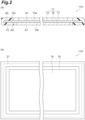
- FIG. 2 is a view illustrating an example of the electrode unit.
- FIG. 2(a) is a cross-sectional view and
- FIG. 2(b) is a plan view.
- an electrode unit 11A including the bipolar electrode 11 is exemplified.
- the electrode unit 11A includes the bipolar electrode 11 and the first resin layer 21 welded to the bipolar electrode 11.
- the one surface (front surface) 15a and the other surface (rear surface) 15b of the current collector 15 include a first region A1 where an active material layer (the positive electrode active material layer 16 or the negative electrode active material layer 17) is formed and a second region A2 exposed from the active material layer.
- the first resin layer 21 is welded to the one surface 15a and the other surface 15b of the current collector 15 in the second region A2.
- the electrode unit 11A including the bipolar electrode 11 is illustrated, but in the power storage module 1, an electrode unit including the positive terminal electrode 13 and an electrode unit including the negative terminal electrode 12 are also constructed.
- the electrode unit including the positive terminal electrode 13 is different from the electrode unit 11A in that the negative electrode active material layer 17 is not formed on the other surface 15b of the current collector 15, and the electrode unit including the negative terminal electrode 12 is different from the electrode unit 11A in that the positive electrode active material layer 16 is not formed on the one surface 15a of the current collector 15, and the other configurations are common.
- the stacked body 10 is constituted by stacking a plurality of the above-described electrode units through the second resin layer 23 and the separator 14.
- an electrode unit manufacturing device and an electrode unit manufacturing method will be described by using the electrode unit 11A as an example.
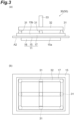
- FIG. 3 is a schematic view illustrating a part of the electrode unit manufacturing device.
- FIG. 3(a) is a side view and FIG. 3(b) is a plan view.
- an electrode unit manufacturing device 50 includes a robot hand (transport unit) 30.
- the robot hand 30 includes a plurality of suction pads 31, an air pipe 32, and a support unit 33.
- the robot hand 30 is connected to a drive unit (not illustrated) through the support unit 33, and can three dimensionally move by the drive unit.
- the plurality of suction pads 31 are arranged to be separated from each other.
- the plurality of suction pads 31 are arranged to be distributed over the entirety of the active material layer in the same plane when the negative electrode active material layer 17 (or the positive electrode active material layer 16, hereinafter, simply referred to as "active material layer”) is disposed to face the robot hand 30.
- the air pipe 32 is connected to each of the plurality of suction pads 31.
- the air pipe 32 performs air intake and air exhaust inside the plurality of suction pads 31, thereby suctioning a member (for example, the negative electrode active material layer 17) disposed to face the plurality of suction pads 31 to the suction pads 31 or releasing the suction of the member in the suction pads 31.
- the support unit 33 is connected to the air pipe 32, and supports the air pipe 32 and the suction pad 31 to the robot hand 30.
- a pipe communicating with the air pipe 32 may be provided inside the support unit 33.
- the suction pads 31 suction the active material layer, and thus the bipolar electrode 11 can be transported in the air to any position while being suctioned and held.
- transportation by the robot hand 30 is performed in such a manner that a surface that is suctioned by the suction pads 31 in the bipolar electrode 11 becomes an upper surface in a vertical direction (direction of gravity).
- the transportation in the air represents transportation in a state in which a surface opposite to a surface suctioned to the suction pads 31 of the bipolar electrode 11 does not come into contact with and is not supported by another device or member.
- the plurality of suction pads 31 are disposed and arranged over the entirety of the active material layer. Accordingly, when the robot hand 30 suctions and supports the bipolar electrode 11, bending of the bipolar electrode 11 is suppressed.
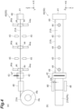
- FIG. 4 and FIG. 5 are schematic views illustrating another part of the electrode unit manufacturing device.
- an orthogonal coordinate system including an X-axis, a Y-axis, and a Z-axis is illustrated.
- an X-axis direction and a Y-axis direction are first and second horizontal direction
- a Z-axis direction is a vertical direction.
- FIG. 4(a) is a side view (view when viewed from the Y-direction)
- FIG. 4(b) is a plan view (view when viewed from the Z-direction)
- FIG. 5 is another side view (view when viewed from the X-direction).
- the electrode unit manufacturing device 50 includes a welding device 40.
- the welding device 40 includes a first grip unit 41, a second grip unit 42, a cutting unit 43, a plurality of pairs of suction units (arrangement units) 44, a plurality of pairs of welding units 45, moving units 46 and 47, a pair of guide units 48, and a plurality of sensors 49.
- a support unit PA that holds a base material 21A for a resin member 21B is disposed at a front stage of the welding device 40.
- the base material 21A is wound around a reel PR and is held in a roll shape.
- the resin member 21B is obtained by cutting the base material 21A in an appropriate length.
- the resin member 21B is a member that becomes a part of the first resin layer 21.
- the first grip unit 41 When the first grip unit 41 is moved along the X-axis direction by the moving unit 46 while gripping one end of the base material 21A held by the support unit PA, the base material 21A is pulled out from the support unit PA.
- the first grip unit 41 is, for example, a chuck.
- the second grip unit 42 further grips the base material 21A that is pulled out due to movement of the first grip unit 41 at a position spaced apart from the first grip unit 41 (by approximately a length of the first resin layer 21).
- the second grip unit 42 is a pair of elastic members (for example, sponges) disposed to sandwich the base material 21A therebetween along the Z-direction, and can grip the base material 21A by sandwiching the base material 21A along the Z-direction.
- the cutting unit 43 cuts out the base material 21A while maintaining a state in which the base material 21A is gripped by the first grip unit 41 and the second grip unit 42 to form the first resin layer 21 in a state of being gripped by the first grip unit 41 and the second grip unit 42.
- the cutting unit 43 includes, for example, a Thomson blade, and cuts out the base material 21A at a position where the base material 21A is gripped by the second grip unit 42. According to this, a rectangular resin member 21B is formed between the first grip unit 41 and the second grip unit 42.
- the plurality of pairs of suction units 44 are suction pads and are dispersed and arranged along a longitudinal direction (here, the X-axis direction) of the resin member 21B at a position between the first grip unit 41 and the second grip unit 42.
- a pair of suction units 44 are disposed to face each other through the resin member 21B along the Z-axis direction. In other words, each of the pair of suction units 44 is disposed to vertically sandwich the resin member 21B.
- the plurality of pairs of suction units 44 include a group of suction units 44 (hereinafter, may be referred to as "upper suction units”) arranged on an upper side of the resin member 21B in the Z-axis direction, and a group of suction units 44 (hereinafter, may be referred to as “lower suction units”) arranged on a lower side of the resin member 21B in the Z-axis direction.
- Each of the suction units 44 is supported by an air tube and a support unit 44a that is an upper and lower cylinder, and is movable along the Z-axis direction. That is, a pair of the suction units 44 are movable so that an interval therebetween in the Z-axis direction varies.
- the first grip unit 41 moves while gripping a pair of the base materials 21A which are stacked and held in the support unit PA, thereby pulling out the pair of base materials 21A overlapped each other from the support unit PA.
- the second grip unit 42 grips the pair of base materials 21A pulled out due to movement of the first grip unit 41 at a position spaced apart from the first grip unit 41.
- the cutting unit 43 collectively cuts out the pair of base materials 21A while maintaining a state in which the base materials 21A are gripped by the first grip unit 41 and the second grip unit 42, and the cut-out base materials 21A are overlapped in the Z-axis direction.
- the pair of resin members 21B in a state of being gripped by the first grip unit 41 and the second grip unit 42 are collectively formed.
- each upper suction unit and each lower suction unit can be moved to approach the resin members 21B, and can suction each of the pair of resin members 21B when being brought into contact with each of the pair of resin members 21B.
- each of the upper suction unit and the lower suction unit can be moved to be spaced apart from each other in a state of suctioning each of the pair of resin members 21B, and can enlarge an interval DB between the pair of the resin members 21B (also can reduce the interval DB when being moved in an opposite direction). That is, the suction units 44 can change the interval DB between the pair of resin members 21B through movement in the stacking direction (Z-axis direction) of the resin members 21B while suctioning at least one of (here, both) the pair of resin members 21B.
- the robot hand 30 can transport the bipolar electrode 11 in such a manner that the second regions A2 of the one surface 15a and the other surface 15b of the current collector 15 are sandwiched between the pair of resin members 21B in a state in which the interval DB therebetween is enlarged due to movement of the suction unit 44.
- the resin members 21B are arranged with respect to the bipolar electrode 11 so that the second regions A2 face the resin members 21B.
- the suction units 44 function as an arrangement unit that holds the resin members 21B before being welded to the bipolar electrode 11 and arranges the resin members 21B on the one surface 15a and the other surface 15b of the bipolar electrode 11 in a state of being suctioned and held in the air by the robot hand 30.
- the plurality of welding units 45 weld the resin members 21B to the bipolar electrode 11.
- a plurality of pairs of the welding units 45 are dispersed and arranged in the longitudinal direction (here, the X-axis direction) of the resin members 21B at a position different from that of the suction units 44.
- a pair of the welding units 45 are arranged to face each other through the resin members 21B along the Z-axis direction.
- the pair of welding units 45 are arranged to vertically sandwich the resin members 21B.
- each of the plurality of welding units 45 can weld each of the pair of resin members 21B to each of the one surface 15a of the current collector 15 and the other surface 15b of the current collector 15 in the second region A2.
- Each of the welding units 45 is a device that heats each of the resin members 21B in a contact or non-contact manner, and is constituted, for example, by a soldering iron or a laser welding machine.
- each of the welding units 45 welds each of the pair of resin members 21B to the current collector 15 in a state in which the pair of resin members 21B are disposed on the one surface 15a and the other surface 15b of the current collector 15 due to movement of the suction units (arrangement unit) 44.
- the moving unit 46 is provided in the first grip unit 41 and moves the first grip unit 41.
- the moving unit 47 is provided in the second grip unit 42 and moves the second grip unit 42. Accordingly, the moving units 46 and 47 can adjust the position of the resin members 21B by moving the first grip unit 41 and the second grip unit 42 in a state in which the first grip unit 41 and the second grip unit 42 grip the resin members 21B.
- the moving units 46 and 47 are devices which horizontally move the first grip unit 41 and the second grip unit 42 in the Y-axis direction, and are constituted, for example, by a ball screw.
- the pair of guide units 48 are provided at a taking-out position of the base materials 21A at the support unit PA.
- the pair of guide units 48 are disposed to face each other in the Y-axis direction intersecting a pulling-out direction (X-axis direction) of the base materials 21Ain a plan view, and restrict movement of the base materials 21A in the Y-axis direction.
- the base materials 21A are sandwiched between the pair of guide units 48, and a slight clearance DA is provided between the guide units 48 and the base materials 21A along the Y-axis direction.
- the moving units 46 and 47 can perform alignment of the resin members 21B with respect to the Y-axis direction by moving the first grip unit 41 and the second grip unit 42 along the Y-axis direction in a state in which the first grip unit 41 and the second grip unit 42 grip the resin members 21B.
- the sensor 49 can detect the resin members 21B, and the moving units 46 and 47 can perform alignment of the resin members 21B on the basis of a detection result of the sensor 49.
- the moving units 46 and 47 can perform alignment of the resin members 21B with respect to the Y-axis direction so that an edge of the resin members 21B is detected by a plurality of (here, two) sensors 49 (for example, a photoelectric sensor or a camera) arranged along the X-axis direction.
- the moving units 46 and 47 are provided independently from each other, and the amount of movement of the first grip unit 41 along the Y-axis direction and the amount of movement of the second grip unit 42 along the Y-axis direction can be set to be different from each other. According to this, an inclination of the resin members 21B with respect to the X-axis direction can also be corrected.
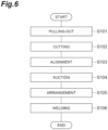
- FIG. 6 is a flowchart illustrating a step of the electrode unit manufacturing method.
- step S101 pulling-out of the base material 21A from the support unit PA. More specifically, in the step S101, the first grip unit 41 of the welding device 40 is moved along the X-axis direction by the moving unit 46 while gripping one end of the base material 21A held by the support unit PA, thereby pulling out the base materials 21A from the support unit PA.
- a pair of the base materials 21A overlapping each other are pulled out.
- the base materials 21A are cut (step S102). More specifically, in the step S102, first, the second grip unit 42 further grips the base materials 21A pulled out due to movement of the first grip unit 41 at a position spaced apart from the first grip unit 41. In the step S102, in this state, the cutting unit 43 cuts out the base materials 21A to form the resin member 21B in a state of being gripped by the first grip unit 41 and the second grip unit 42. Here, as described above, a pair of the resin members 21B overlapped each other are formed.
- step S103 Alignment of the resin members 21B is performed (step S103). More specifically, in the step S103, the moving units 46 and 47 move the first grip unit 41 and the second grip unit 42 in a state of gripping the resin members 21B along the Y-axis direction on the basis of a detection result of the sensor 49 on the resin members 21B, thereby performing alignment of the pair of resin members 21B with respect to the Y-axis direction. According to this, the pair of resin members 21B are aligned with respect to each of the welding units 45, and are set to a defined welding position.
- step S104 suctioning of the resin members 21B is performed (step S104). More specifically, in the step S104, each of the pair of resin members 21B is suctioned by each upper suction unit and each lower suction unit arranged with the pair of resin members 21B sandwiched therebetween. In this state, after releasing gripping of the resin members 21B by the first grip unit 41 and the second grip unit 42, each upper suction unit and each lower suction unit are moved to be spaced apart from each other, thereby enlarging the interval DB between the pair of resin members 21B.
- the bipolar electrode 11 is disposed with respect to the resin members 21B (step S105, first step). More specifically, in the step S105, the robot hand 30 transports the bipolar electrode 11 in the air in such a manner that the second regions A2 of the one surface 15a and the other surface 15b of the current collector 15 of the bipolar electrode 11 face the resin members 21B while suctioning and holding the bipolar electrode 11.
- the robot hand 30 transports the bipolar electrode 11 in such a manner that the second regions A2 is sandwiched between the pair of resin members 21B in a state in which the interval DB therebetween is enlarged due to movement of the suction units 44.
- the pair of resin members 21B are respectively disposed on the one surface 15a and the other surface 15b of the current collector 15. That is, in the step S105, the suction units 44 hold the resin members 21B before welding to the bipolar electrode 11, and dispose the resin members 21B on the current collector 15 (the one surface 15a and the other surface 15b) of the bipolar electrode 11 in a state of being suctioned and held in the air by the robot hand 30.
- the pair of resin members 21B are welded to the bipolar electrode 11 (step S106, second step). More specifically, in the step S106, the welding units 45 weld the pair of resin members 21B to the one surface 15a and the other surface 15b of the current collector 15, respectively, in the second regions A2. That is, in the step S106, the welding units 45 weld the pair of resin members 21B to the current collector 15 in a state in which the pair of resin members 21B are disposed on the one surface 15a and the other surface 15b of the current collector 15 due to movement of the suction units 44.
- the welding units 45 are scattered in the longitudinal direction of the resin members 21B. Accordingly, here, temporary welding in which the resin members 21B are spot-welded and fixed to the current collector 15 by the welding units 45 at a plurality of positions in the longitudinal direction of the resin members 21B is performed.
- the resin members 21B can be collectively welded to two side portions of the current collector 15 of the bipolar electrode 11. Then, when the same step is performed again with respect to other two side portions of the current collector 15 of the bipolar electrode 11, the resin members 21B are provided (temporarily welded) over the entire periphery of the peripheral edge portion 15c of the current collector 15. Accordingly, when the entirety of the resin members 21B is welded to the current collector and the resin members 21B are integrated in the subsequent step, the first resin layer 21 having a frame shape is provided with respect to the peripheral edge portion 15c of the current collector 15, and the electrode unit 11A is obtained.
- the electrode unit manufacturing device 50 is configured to manufacture the electrode unit 11A by welding the resin members 21B to the bipolar electrode 11 including the current collector 15 and the active material layer provided on the one surface 15a and the other surface 15b of the current collector 15.
- the electrode unit manufacturing device 50 includes the robot hand 30 that transports the bipolar electrode 11 in the air while suctioning and holding the bipolar electrode 11, and the welding device 40 including the welding units 45 that weld the resin members 21B to the bipolar electrode 11 in a state of being suctioned and held in the air by the robot hand 30.
- the electrode unit manufacturing method is configured to manufacture the electrode unit 11A by welding the resin members 21B to the bipolar electrode 11 including the current collector 15 and the active material layer provided on the one surface 15a and the other surface 15b of the current collector 15.
- the electrode unit manufacturing method includes the first step of transporting the bipolar electrode 11 in the air while suctioning and holding the bipolar electrode 11, and the second step of welding the resin members 21B to the bipolar electrode 11 in a state of being suctioned and held in the air after the first step.
- the resin members 21B when manufacturing the electrode unit 11A by welding the resin members 21B to the bipolar electrode 11, the resin members 21B are welded to the bipolar electrode 11 in a state in which the bipolar electrode 11 is floated in the air in a state of being suctioned and held. Accordingly, it is possible to avoid that foreign matters which slip down from the bipolar electrode 11 adhere to the subsequent bipolar electrode 11. Accordingly, welding of the resin members 21B can be performed while suppressing foreign matters from adhering to the bipolar electrode 11.
- the welding device 40 includes the suction units 344 which hold the resin members 21B before being welded to the bipolar electrode 11, and dispose the resin members 21B on the front surfaces (the one surface 15a and the other surface 15b) of the bipolar electrode 11 in a state of being suctioned and held in the air by the robot hand 30.
- the welding units 45 welds the resin members 21B arranged on the front surfaces by the suction units 44 to the current collector 15. In this way, here, the resin members 21B are arranged and welded with respect to the front surfaces of the current collector 15 of the bipolar electrode 11. Accordingly, it is possible to avoid that foreign matters which slip down from the bipolar electrode 11 adhere to the subsequent electrode. As a result, it is possible to avoid that foreign matters are interposed between the bipolar electrode 11 and the resin members 21B when arranging and welding the resin members 21B.
- the one surface 15a and the other surface 15b of the current collector 15 include the first region A1 where the active material layer is formed, and the second region A2 exposed from the active material layer, and the robot hand 30 transports the bipolar electrode 11 in such a manner that the second regions A2 face the resin members 21B.
- the welding units 45 weld the resin members 21B to the current collector 15 at the second regions A2.
- the resin members 21B are arranged and welded with respect to the second regions A2 exposed from the active material layer in the current collector 15 of the bipolar electrode 11. Accordingly, it is possible to avoid that foreign matters which slip down from the bipolar electrode 11 adhere to the subsequent bipolar electrode 11. As a result, it is possible to avoid that foreign matters are sandwiched between the bipolar electrode 11 and the resin members 21B in the second regions A2.
- the welding device 40 includes the first grip unit 41 that moves while gripping one end of the base materials 21A for the resin members 21B which are held by the support unit PA to pull out the base materials 21A from the support unit PA, the second grip unit 42 that further grips the base materials 21A pulled out due to movement of the first grip unit 41 at a position spaced apart from the first grip unit 41, and the cutting unit 43 that cuts out the base materials 21A while maintaining a state in which the base materials 21A are gripped by the first grip unit 41 and the second grip unit 42 to form the resin members 21B. Accordingly, formation of the resin members 21B from the base materials 21A can be easily performed.
- the welding device 40 includes the sensor 49 that detects the resin members 21B in a state of being gripped by the first grip unit 41 and the second grip unit 42 after being formed due to cutting-out of the base materials 21A by the cutting unit 43, and the moving units 46 and 47 which perform alignment of the resin members 21B by moving the first grip unit 41 and the second grip unit 42 on the basis of a detection result of the sensor 49 before the resin members 21B are held by the suction units 44. Therefore, positional accuracy of the resin members 21B with respect to a welding position is improved.
- the first grip unit 41 moves while gripping a pair of the base materials 21A which are stacked and held in the support unit PA to pull out the pair of the base materials 21A from the support unit PA.
- the second grip unit 42 further grips the pair of base materials 21A pulled out due to movement of the first grip unit 41 at a position spaced apart from the first grip unit 41, and the cutting unit 43 cuts out the pair of base materials 21A to form a pair of the resin members 21B.
- the welding device 40 includes the suction units 44 that move in the stacking direction of the resin members 21B while suctioning at least one of the pair of resin members 21B formed by cutting the base materials 21A by the cutting unit 43 to change the interval DB between the pair of resin members 21B.
- the robot hand 30 transports the bipolar electrode 11 in such a manner that the second regions A2 are sandwiched between the pair of resin members 21B in which the interval DB is enlarged due to movement of the suction units 44.
- the welding units 45 weld the pair of resin members 21B to the one surface 15a and the other surface 15b of the current collector 15 in a state in which the pair of resin members 21B are respectively disposed on the one surface 15a and the other surface 15b of the current collector 15 due to movement of the suction units 44.
- the pair of resin members 21B can be formed and welded with respect to the one surface 15a and the other surface 15b of the current collector 15 through pulling-out of the base materials 21A by the first grip unit 41 which is performed once, and cutting-out of the base materials 21A by the cutting unit 43 which is performed once.
- the robot hand 30 transports an electrode formed by temporarily welding a plurality of (four) resin members 21B to the current collector 15 as described above to a separate welding device while suctioning and holding the electrode.
- the entirety of the plurality of resin members 21B is welded to the current collector 15 by an impulse sealer of the separate welding device. According to this, main welding of the resin members 21B is performed, and the first resin layer 21 is formed at the peripheral edge portion 15c of the current collector 15 (that is, the electrode unit 11A is manufactured).
- the electrode of the electrode unit manufacturing device is not limited to the bipolar electrode 11 described above, and may be set to, for example, any electrode such as the positive terminal electrode 13 and the negative terminal electrode 12 in which the active material layer is provided only one surface of the current collector.
- the resin member that is welded to the electrode is not limited to a resin member that constitutes the first resin layer 21, and may be, for example, any resin member that constitutes the second resin layer 23.
- a transport unit that transports an electrode in the air by suctioning and holding the electrode is not limited to the above-described robot hand 30, and another device such as a ceiling transport device may be used.
- the arrangement unit that holds the resin member 21B before being welded to the electrode is not limited to the above-described suction unit 44, and another device such as a grip device that grips the resin member 21B from a direction (Z-axis direction) intersecting the stacking direction of the resin member 21B.
- FIG. 8 is a view illustrating a modification example of the welding device.
- FIG. 8(a) is a side view (view when viewed from the Y-direction)
- FIG. 8(b) is a plan view (view when viewed from the Z-direction).
- the welding device 40 that is, the electrode unit manufacturing device 50
- the welding device 40 may further include a moving unit 44b and a sensor 59.
- the moving unit 44b is provided in each of the plurality of pairs of suction units 44.
- the moving unit 44b can move the suction units 44 along at least the Y-axis direction.
- the moving units 44b moves the suction units 44 along the Y-axis direction in a state in which the suction units 44 suction (hold) the resin members 21B, thereby performing alignment of the resin members 21B with respect to the y-axis direction. At this time, gripping of the resin member 21B by the first grip unit 41 and the second grip unit 42 may be released.
- the sensor 49 can detect the resin member 21B suctioned by the suction units 44, and the moving units 44b can perform alignment of the resin member 21B on the basis of a detection result of the sensor 49.
- the moving units 44b can perform alignment of the resin member 21B with respect to the Y-axis direction in such a manner that an edge of the resin member 21B is detected by a plurality of the sensors 49 arranged along the X-axis direction.
- a plurality of the moving units 44b are provided independently from each other, and when the amount of movement along the Y-axis direction is set to be different in each case, an inclination of the resin member 21B with respect to the X-axis direction can be corrected.
- the function of the moving units 46 and 47 which relates to the alignment of the resin member 21B may be omitted.
- the moving units 46 and 47 are not provided.
- the welding device 40 is provided with the moving units 44b
- procedures of the step S103 and the step S104 in the above-described electrode unit manufacturing method may be exchanged with each other. That is, in this case, first, in the step S104, the resin member 21B is suctioned and held by the suction units 44. Then, for example, after releasing gripping of the resin member 21B by the first grip unit 41 and the second grip unit 42, in the step S103, the moving units 44b move the suction units 44 in a state of holding the resin member 21B along the Y-axis direction on the basis of the detection result of the sensor 49 on the resin member 21B, thereby performing alignment of the resin member 21B with respect to the Y-axis direction. According to this, the resin member 21B is aligned with respect to each of the welding units 45, and is set to a defined welding position.
- the welding device 40 may further include the sensor 59.
- the sensor 59 is disposed at a tip end of the base material 21A in the pulling-out direction (here, the X-axis direction).
- the sensor 59 is a photoelectric sensor or a camera, and can be disposed to detect a boundary between the base material 21A and the first grip unit 41 when pulling out the base material 21A by a defined length as an example. According to this, the welding device 40 can determine whether or not the pulling-out length of the base material 21A is sufficient on the basis of a detection result of the sensor 59.
- the welding device 40 may not include the first grip unit 41, the second grip unit 42, and the cutting unit 43.
- the resin member 21B can be supplied from the outside.
- the suction units (arrangement units) 44 can suction and hold the resin member 21B supplied from the outside or can dispose the resin member 21B on the one surface 15a and the other surface 15b of the bipolar electrode 11.
- the welding device 40 there is no limitation to a case where after a pair of stacked base materials 21A are pulled out from the support unit PA, a pair of resin members 21B in which the interval DB therebetween is enlarged due to movement of the suction units 44 in the Z-axis direction is obtained.
- the base material 21A may be pulled out from a plurality of support units which respectively hold a pair of base materials 21A, and the resin members 21B may be constituted by cutting the base materials 21A.
- 11 bipolar electrode (electrode), 11A: electrode unit, 15: current collector, 15a: one surface (front surface), 15b: another surface (rear surface), 21A: base material, 21B: resin member, 30: robot hand (transport unit), 40: welding device, 41: first grip unit, 42: second grip unit, 43: cutting unit, 44: suction unit (arrangement unit), 44b: moving unit, 45: welding unit, 46, 47: moving unit, 48: guide unit, 49: sensor, 50: electrode unit manufacturing device.
Landscapes
- Engineering & Computer Science (AREA)
- Manufacturing & Machinery (AREA)
- Chemical & Material Sciences (AREA)
- Chemical Kinetics & Catalysis (AREA)
- Electrochemistry (AREA)
- General Chemical & Material Sciences (AREA)
- Mechanical Engineering (AREA)
- Power Engineering (AREA)
- Microelectronics & Electronic Packaging (AREA)
- Materials Engineering (AREA)
- Battery Electrode And Active Subsutance (AREA)
Abstract
Description
- The present disclosure relates to an electrode unit manufacturing device and an electrode unit manufacturing method.
-
Patent Literature 1 discloses a method of forming a bipolar electrode unit by welding a resin frame to a bipolar electrode. In this method, first, in a state in which the resin frame is temporarily fixed to a first surface of an electrode plate of the bipolar electrode, the bipolar electrode and the resin frame are transported between a pair of pressing members of which a predetermined clearance is adjusted. Then, the electrode plate of the bipolar electrode and the resin frame are heated by a heater, are pressed by a compression roller, and are cooled by a cooling plate. According to this, the resin frame is welded to the electrode plate of the bipolar electrode, thereby forming the bipolar electrode unit. - Patent Literature 1:
Japanese Unexamined Patent Publication No. 2020-95909 - By the way, when the resin member is temporarily fixed (for example, temporarily welded) or welded to the electrode as in the method described in
Patent Literature 1, it is considered that welding is performed in a state in which the electrode in each stage is placed on a stage or a pallet. In this way, when the electrode is placed on the stage or the pallet, there is a concern that metal pieces of a current collector constituting the electrode, or foreign matters such as an active material of an active material layer which slip down from the electrode may adhere to the stage or the pallet and remain. Accordingly, in this case, when the subsequent electrode is placed on the stage or the pallet, there is a concern that the foreign matters may adhere to the electrode. - Here, an object of the present disclosure is to provide an electrode unit manufacturing device and an electrode unit manufacturing method which are capable of welding a resin member while suppressing adhesion of foreign matters to an electrode.
- An electrode unit manufacturing device according to the present disclosure is an electrode unit manufacturing device for manufacturing an electrode unit by welding a resin member to an electrode including a current collector and an active material layer provided on a front surface of the current collector. The electrode unit manufacturing device includes a transport unit configured to transport the electrode in the air while suctioning and holding the electrode, and a welding device including a welding unit configured to weld the resin member to the electrode in a state of being suctioned and held in the air by the transport unit.
- An electrode unit manufacturing method according to the present disclosure is an electrode unit manufacturing method for manufacturing an electrode unit by welding a resin member to an electrode including a current collector and an active material layer provided on a front surface of the current collector. The electrode unit manufacturing method includes a first step of transporting the electrode in the air while suctioning and holding the electrode, and a second step of welding the resin member to the electrode in a state of being suctioned and held in the air after the first step.
- In the manufacturing device and the manufacturing method, when manufacturing the electrode unit by welding the resin member to the electrode, the resin member is welded to the electrode in a state in which the electrode is suctioned and held in the air. Accordingly, it is possible to avoid that foreign matters which slip down from the electrode adhere to the subsequent electrode. As a result, it is possible to weld the resin member while suppressing adhesion of foreign matters to the electrode.
- In the electrode unit manufacturing device according to the present disclosure, the welding device may include an arrangement unit configured to hold the resin member before being welded to the electrode and to arrange the resin member on the front surface of the electrode in the state of being suctioned and held in the air by the transport unit, and the welding unit may weld the resin member arranged on the front surface by the arrangement unit to the current collector. In this case, the resin member is arranged and welded with respect to the front surface of the current collector of the electrode. Accordingly, it is possible to avoid that foreign matters which slip down from the electrode adhere to the subsequent electrode. As a result, during arrangement and welding of the resin member, it is possible to avoid foreign matters from being sandwiched between the electrode and the resin member.
- In the electrode unit manufacturing device according to the present disclosure, the welding device may include a first grip unit configured to move while gripping one end of a base material held by a support unit to pull out the base material from the support unit, a second grip unit configured to further grip the base material pulled out by movement of the first grip unit at a position spaced apart from the first grip unit, and a cutting unit configured to cut out the base material while maintaining a state where the base material is gripped by the first grip unit and the second grip unit to form the resin member. In this case, the resin member can be easily formed from the base material.
- In the electrode unit manufacturing device according to the present disclosure, the welding device may include a sensor configured to detect the resin member in a state of being gripped by the first grip unit and the second grip unit, and a moving unit configured to perform alignment of the resin member on the basis of a detection result of the sensor by moving the first grip unit and the second grip unit before the resin member is held by the arrangement unit. In this case, positional accuracy of the resin member with respect to a welding position is improved.
- In the electrode unit manufacturing device according to the present disclosure, the first grip unit may move while gripping a pair of the base materials stacked and held in the support unit to pull out the pair of base materials from the support unit, the second grip unit may further grip the pair of base materials pulled out by movement of the first grip unit at a position spaced apart from the first grip unit, the cutting unit may cut the pair of base materials to form a pair of the resin members, the arrangement unit may move in a stacking direction of the resin members while holding at least one of the pair of resin members to change an interval between the pair of resin members, the transport unit may transport the electrode in such a manner that the current collector is sandwiched between the pair of resin members in a state in which an interval between the pair of the resin members is enlarged due to movement of the arrangement unit, and the welding unit may weld each of the pair of resin members to the current collector in a state in which the pair of resin members are respectively arranged on the front surface of the current collector and a rear surface opposite to the front surface of the current collector due to movement of the arrangement unit. In this case, the pair of resin members can be formed and welded with respect to each of the front surface and rear surface of the current collector by pulling-out of the base material by the first grip unit which is performed once, and cutting-out of the base material by the cutting unit which is performed once.
- In the electrode unit manufacturing device according to the present disclosure, the welding device may include a sensor configured to detect the resin member in a state of being held by the arrangement unit, and a moving unit configured to move the arrangement unit in a state in which the resin member is held by the arrangement unit to perform alignment of the resin member on the basis of a detection result of the sensor. In this case, positional accuracy of the resin member with respect to a welding position is improved.
- According to the present disclosure, it is possible to provide an electrode unit manufacturing device and an electrode unit manufacturing method which are capable of welding a resin member while suppressing adhesion of foreign matters to an electrode.
-
-
FIG. 1 is a schematic cross-sectional view of a power storage module according to an embodiment. -
FIG. 2 is a view illustrating an example of an electrode unit. -
FIG. 3 is a schematic view illustrating a part of an electrode unit manufacturing device. -
FIG. 4 is a schematic view illustrating another part of the electrode unit manufacturing device. -
FIG. 5 is a schematic view illustrating still another part of the electrode unit manufacturing device. -
FIG. 6 is a flowchart illustrating a step of an electrode unit manufacturing method. -
FIG. 7 is a side view illustrating a step of the electrode unit manufacturing method. -
FIG. 8 is a view illustrating a modification example of a welding device. - Hereinafter, an embodiment according to the present disclosure will be described in detail with reference to the accompanying drawings. Note that, in description of the drawings, the same reference numeral will be given to the same or equivalent element, and redundant description may be omitted.
-
FIG. 1 is a schematic cross-sectional view of a power storage module according to this embodiment. Apower storage module 1 shown inFIG. 1 is a power storage module that is used, for example, in batteries of various vehicles such as a fork lift, a hybrid vehicle, and an electric vehicle. For example, thepower storage module 1 is a secondary battery such as a nickel-hydrogen secondary battery and a lithium ion secondary battery. Thepower storage module 1 may be an electric double layer capacitor or a solid state battery. Here, a case where thepower storage module 1 is the lithium ion secondary battery is exemplified. - The
power storage module 1 includes a stackedbody 10 and aresin frame 22. Thestacked body 10 includes a plurality ofbipolar electrodes 11, anegative terminal electrode 12, a positiveterminal electrode 13, a plurality ofseparators 14, a plurality offirst resin layers 21, a plurality ofsecond resin layers 23, and an electrolyte (not illustrated). - Each of the
bipolar electrodes 11 includes acurrent collector 15, a positive electrodeactive material layer 16, and a negative electrodeactive material layer 17. For example, thecurrent collector 15 has a rectangular sheet shape. The positive electrodeactive material layer 16 is provided on onesurface 15a of thecurrent collector 15. The negative electrodeactive material layer 17 is provided on theother surface 15b of thecurrent collector 15. The plurality ofbipolar electrodes 11 are stacked so that the positive electrodeactive material layer 16 of onebipolar electrode 11, and the negative electrodeactive material layer 17 of anotherbipolar electrode 11 face each other. Here, a direction in which thebipolar electrodes 11 are stacked is referred to as a stacking direction D. - The positive electrode
active material layer 16 and the negative electrodeactive material layer 17 have a rectangular shape when viewed from the stacking direction D. The negative electrodeactive material layer 17 is one size larger than the positive electrodeactive material layer 16 when viewed from the stacking direction D. That is, in a plan view from the stacking direction D, the entirety of a formation region of the positive electrodeactive material layer 16 is located within a formation region of the negative electrodeactive material layer 17. - The
negative terminal electrode 12 includes thecurrent collector 15, and the negative electrodeactive material layer 17 provided on theother surface 15b of thecurrent collector 15. Thenegative terminal electrode 12 does not include the positive electrodeactive material layer 16. That is, an active material layer is not provided on the onesurface 15a of thecurrent collector 15 of the negativeterminal electrode 12. The negativeterminal electrode 12 is stacked on thebipolar electrode 11 at one end of the stackedbody 10 in the stacking direction D. The negativeterminal electrode 12 is stacked on thebipolar electrode 11 so that the negative electrodeactive material layer 17 faces the positive electrodeactive material layer 16 of thebipolar electrode 11. Accordingly, the onesurface 15a of thecurrent collector 15 of the negativeterminal electrode 12 faces an outer side of the stackedbody 10, and a part thereof is exposed to the outside of the stackedbody 10. - The positive
terminal electrode 13 includes thecurrent collector 15, and the positive electrodeactive material layer 16 provided on the onesurface 15a of thecurrent collector 15. The positiveterminal electrode 13 does not include the negative electrodeactive material layer 17. That is, an active material layer is not provided on theother surface 15b of thecurrent collector 15 of the positiveterminal electrode 13. The positiveterminal electrode 13 is stacked on thebipolar electrode 11 at the other end of the stackedbody 10 in the stacking direction D. The positiveterminal electrode 13 is stacked on thebipolar electrode 11 so that the positive electrodeactive material layer 16 faces the negative electrodeactive material layer 17 of thebipolar electrode 11. Accordingly, theother surface 15b of thecurrent collector 15 of the positiveterminal electrode 13 faces an outer side of the stackedbody 10, and a part thereof is exposed to the outside of the stackedbody 10. - Each of the
separators 14 is disposed between thebipolar electrodes 11 adjacent to each other, between the negativeterminal electrode 12 and thebipolar electrode 11, and between the positiveterminal electrode 13 and thebipolar electrode 11. Theseparator 14 is interposed between the positive electrodeactive material layer 16 and the negative electrodeactive material layer 17. Theseparator 14 isolates the positive electrodeactive material layer 16 and the negative electrodeactive material layer 17 from each other, and allows a charger carrier such as lithium ions to pass therethrough while preventing short-circuit due to contact between adjacent electrodes. - The
current collector 15 is a chemically inert electric conductor that allows a current to continuously flow through the positive electrodeactive material layer 16 and the negative electrodeactive material layer 17 during discharging or charging of the lithium ion secondary battery. Examples of a material of thecurrent collector 15 include a metallic material, a conductive resin material, a conductive inorganic material, and the like. Examples of the conductive resin material include a resin in which a conductive filler is added to a conductive polymer material or a non-conductive polymer material as necessary, and the like. Thecurrent collector 15 may include a plurality of layers. In this case, each layer of thecurrent collector 15 may contain a metallic material or a conductive resin material. - A coating layer may be formed on a front surface of the
current collector 15. The coating layer may be formed by a known method such as a plating treatment and a spray coating. Thecurrent collector 15 may have, for example, a plate shape, a foil shape (for example, metal foil), a film shape, a mesh shape, or the like. Examples of the metal foil include aluminum foil, copper foil, nickel foil, titanium foil, stainless steel foil, and the like. Examples of the stainless steel foil include SUS 304, SUS 316, SUS 301, and the like which are defined in JIS G 4305:2015. When using the stainless steel foil as thecurrent collector 15, the mechanical strength of thecurrent collector 15 can be secured. Thecurrent collector 15 may be alloy foil the metals or foil in which a plurality of pieces of the metal foil are integrated. In a case where thecurrent collector 15 has a foil shape, the thickness of thecurrent collector 15 may be, for example, 1 µm to 100 µm. - The positive electrode
active material layer 16 contains a positive electrode active material capable of intercalating and deintercalating a charge carrier such as lithium ions. Examples of the positive electrode active material include lithium composite metal oxides having a layered rock salt structure, metal oxides having a spinel structure, polyanionic compounds, and the like. The positive electrode active material may be a material that can be used in the lithium ion secondary battery. The positive electrodeactive material layer 16 may contain a plurality of positive electrode active materials. In this embodiment, the positive electrodeactive material layer 16 contains olivine-type lithium iron phosphate (LiFePO4) as a composite oxide. - The negative electrode
active material layer 17 contains a negative electrode active material capable of intercalating and deintercalating a charge carrier such as lithium ions. The negative electrode active material may be any of an elementary substance, an alloy, and a compound. Examples of the negative electrode active material include Li, carbon, a metal compound, and the like. The negative electrode active material may be an element that can be alloyed with lithium, a compound thereof, or the like. Examples of the carbon include natural graphite, artificial graphite, hard carbon (non-graphitizable carbon), soft carbon (easily graphitizable carbon), and the like. Examples of the artificial graphite include highly oriented graphite, mesocarbon microbeads, and the like. Examples of the element that can be alloyed with lithium include silicon, tin, and the like. In this embodiment, the negative electrodeactive material layer 17 contains graphite as a carbon-based material. - Each of the positive electrode
active material layer 16 and the negative electrode active material layer 17 (hereinafter, may be simply referred to as "active material layer") may further contain a conductive agent, a binder, an electrolyte (polymer matrix, an ion-conductive polymer, an electrolytic solution, or the like), an electrolyte supporting salt (lithium salt) for enhancing ion conductivity, and the like as necessary. The conductive agent is added to enhance conductivity of each electrode (thebipolar electrode 11, the negativeterminal electrode 12, and the positive terminal electrode 13). Examples of the conductive agent include acetylene black, carbon black, graphite, and the like. - Examples of the binder include fluorine-containing resins such as polyvinylidene fluoride, polytetrafluoroethylene, and fluororubber, thermoplastic resins such as polypropylene and polyethylene, imide-based resins such as polyimide and polyamideimide, alkoxysilyl group-containing resins, acrylic resins such as acrylic acid and methacrylic acid, styrene-butadiene rubber (SBR), carboxymethyl cellulose, alginates such as sodium alginate and ammonium alginate, water-soluble cellulose ester crosslinked products, starch-acrylic acid graft polymers, and the like. The binders can be used alone or in combination. As a solvent, for example, water, N-methyl-2-pyrrolidone (NMP), or the like is used.
- The
separator 14 may be, for example, a porous sheet or nonwoven fabric containing a polymer that absorbs and holds an electrolyte. Examples of a material of theseparator 14 include polypropylene, polyethylene, polyolefin, polyester, and the like. Theseparator 14 may have a single layer structure or a multilayer structure. The multilayer structure may include, for example, an adhesive layer or a ceramic layer as a heat-resistant layer, and the like. Theseparator 14 may be impregnated with an electrolyte. Theseparator 14 may consist of an electrolyte such as a polymer electrolyte and an inorganic electrolyte. Examples of the electrolyte impregnated in theseparator 14 include a liquid electrolyte (electrolytic solution) containing a nonaqueous solvent and an electrolyte salt dissolved in the nonaqueous solvent, a polymer gel electrolyte containing an electrolyte held in a polymer matrix, and the like. - In a case where the
separator 14 is impregnated with an electrolyte, as an electrolyte salt thereof, a known lithium salt such as LiClO4, LiAsF6, LiPF6, LiBF4, LiCF3SO3, LiN(FSO2)2, and LiN(CF3SO2)2 may be used. In addition, as the nonaqueous solvent, known solvents such as cyclic carbonates, cyclic esters, chain carbonates, chain esters, and ethers may be used. Note that, two or more kinds of the known solvent materials may be used in combination. - The
first resin layer 21, theresin frame 22, and thesecond resin layer 23 constitute a sealingportion 20. The sealingportion 20 is formed in a frame shape at a peripheral edge portion of the stackedbody 10 to surround thestacked body 10. The sealingportion 20 is joined to each of the onesurface 15a and theother surface 15b of thecurrent collector 15 at aperipheral edge portion 15c of thecurrent collector 15. The sealingportion 20 seals each space S between a plurality of thecurrent collectors 15 adjacent to each other in the stacking direction D. An electrolyte is accommodated in the space S. In a case where the electrolyte is a liquid, the sealingportion 20 prevents the electrolyte from permeating to the outside. The sealingportion 20 suppresses a moisture and the like from intruding into the space S from the outside of the stackedbody 10. An edge portion of theseparator 14 is embedded in the sealingportion 20. The sealingportion 20 contains an insulating material. Examples of the material of the sealingportion 20 include various resin materials such as polypropylene, polyethylene, polystyrene, an ABS resin, modified polypropylene, and an acrylonitrile styrene resin. - The
first resin layer 21 is provided in each of thecurrent collectors 15. Accordingly, thefirst resin layer 21 is stacked on each other along the stacking direction D. Thefirst resin layer 21 has a frame shape and is provided at theperipheral edge portion 15c of thecurrent collector 15. That is, thefirst resin layer 21 is provided to range from the onesurface 15a of thecurrent collector 15 to theother surface 15b through an end surface, and covers theperipheral edge portion 15c. Thefirst resin layer 21 is welded to the onesurface 15a and theother surface 15b of thecurrent collector 15. - The
second resin layer 23 is disposed to be sandwiched between a plurality of the first resin layers 21 adjacent to each other in the stacking direction D. According to this, thesecond resin layer 23 maintains a space between the first resin layers 21 adjacent to each other, that is, thecurrent collectors 15 adjacent to each other. Thesecond resin layer 23 has a frame shape, and is disposed on theperipheral edge portion 15c of thecurrent collector 15 when viewed from the stacking direction D. Thesecond resin layer 23 can be welded to at least one of a pair of the first resin layers 21 adjacent to each other in the stacking direction D. Here, an end of theseparator 14 is embedded between thefirst resin layer 21 and thesecond resin layer 23. - The
resin frame 22 is formed by integrating a plurality of the first resin layers 21 and a plurality of the second resin layers 23. When an end of thefirst resin layer 21 on a side opposite to the space S, and an end of thesecond resin layer 23 on a side opposite to the space S are welded to each other, theresin frame 22 collectively seals a plurality of the spaces S. A surface of theresin frame 22 on a side opposite to the space S constitutes anouter surface 10s of the stackedbody 10. - In the above-described
power storage module 1, a plurality of electrode units are constituted.FIG. 2 is a view illustrating an example of the electrode unit.FIG. 2(a) is a cross-sectional view andFIG. 2(b) is a plan view. InFIG. 2 , anelectrode unit 11A including thebipolar electrode 11 is exemplified. Theelectrode unit 11A includes thebipolar electrode 11 and thefirst resin layer 21 welded to thebipolar electrode 11. The one surface (front surface) 15a and the other surface (rear surface) 15b of thecurrent collector 15 include a first region A1 where an active material layer (the positive electrodeactive material layer 16 or the negative electrode active material layer 17) is formed and a second region A2 exposed from the active material layer. Thefirst resin layer 21 is welded to the onesurface 15a and theother surface 15b of thecurrent collector 15 in the second region A2. - Note that, in
FIG. 2 , theelectrode unit 11A including thebipolar electrode 11 is illustrated, but in thepower storage module 1, an electrode unit including the positiveterminal electrode 13 and an electrode unit including the negativeterminal electrode 12 are also constructed. As compared with theelectrode unit 11A, the electrode unit including the positiveterminal electrode 13 is different from theelectrode unit 11A in that the negative electrodeactive material layer 17 is not formed on theother surface 15b of thecurrent collector 15, and the electrode unit including the negativeterminal electrode 12 is different from theelectrode unit 11A in that the positive electrodeactive material layer 16 is not formed on the onesurface 15a of thecurrent collector 15, and the other configurations are common. Thestacked body 10 is constituted by stacking a plurality of the above-described electrode units through thesecond resin layer 23 and theseparator 14. Hereinafter, an electrode unit manufacturing device and an electrode unit manufacturing method will be described by using theelectrode unit 11A as an example. -
FIG. 3 is a schematic view illustrating a part of the electrode unit manufacturing device.FIG. 3(a) is a side view andFIG. 3(b) is a plan view. As illustrated inFIG. 3 , an electrodeunit manufacturing device 50 includes a robot hand (transport unit) 30. Therobot hand 30 includes a plurality ofsuction pads 31, anair pipe 32, and asupport unit 33. Therobot hand 30 is connected to a drive unit (not illustrated) through thesupport unit 33, and can three dimensionally move by the drive unit. The plurality ofsuction pads 31 are arranged to be separated from each other. Here, the plurality ofsuction pads 31 are arranged to be distributed over the entirety of the active material layer in the same plane when the negative electrode active material layer 17 (or the positive electrodeactive material layer 16, hereinafter, simply referred to as "active material layer") is disposed to face therobot hand 30. - The
air pipe 32 is connected to each of the plurality ofsuction pads 31. Theair pipe 32 performs air intake and air exhaust inside the plurality ofsuction pads 31, thereby suctioning a member (for example, the negative electrode active material layer 17) disposed to face the plurality ofsuction pads 31 to thesuction pads 31 or releasing the suction of the member in thesuction pads 31. Thesupport unit 33 is connected to theair pipe 32, and supports theair pipe 32 and thesuction pad 31 to therobot hand 30. A pipe communicating with theair pipe 32 may be provided inside thesupport unit 33. - In this way, in the
robot hand 30, thesuction pads 31 suction the active material layer, and thus thebipolar electrode 11 can be transported in the air to any position while being suctioned and held. Note that, transportation by therobot hand 30 is performed in such a manner that a surface that is suctioned by thesuction pads 31 in thebipolar electrode 11 becomes an upper surface in a vertical direction (direction of gravity). In addition, the transportation in the air stated here represents transportation in a state in which a surface opposite to a surface suctioned to thesuction pads 31 of thebipolar electrode 11 does not come into contact with and is not supported by another device or member. As described above, the plurality ofsuction pads 31 are disposed and arranged over the entirety of the active material layer. Accordingly, when therobot hand 30 suctions and supports thebipolar electrode 11, bending of thebipolar electrode 11 is suppressed. -
FIG. 4 andFIG. 5 are schematic views illustrating another part of the electrode unit manufacturing device. In the following drawings, an orthogonal coordinate system including an X-axis, a Y-axis, and a Z-axis is illustrated. As an example, an X-axis direction and a Y-axis direction are first and second horizontal direction, and a Z-axis direction is a vertical direction.FIG. 4(a) is a side view (view when viewed from the Y-direction),FIG. 4(b) is a plan view (view when viewed from the Z-direction), andFIG. 5 is another side view (view when viewed from the X-direction). - As illustrated in
FIG. 4 andFIG. 5 , the electrodeunit manufacturing device 50 includes awelding device 40. Thewelding device 40 includes afirst grip unit 41, asecond grip unit 42, a cuttingunit 43, a plurality of pairs of suction units (arrangement units) 44, a plurality of pairs ofwelding units 45, movingunits guide units 48, and a plurality ofsensors 49. In addition, a support unit PA that holds abase material 21A for aresin member 21B is disposed at a front stage of thewelding device 40. In the support unit PA, thebase material 21A is wound around a reel PR and is held in a roll shape. Theresin member 21B is obtained by cutting thebase material 21A in an appropriate length. Note that, as to be described later, a plurality of theresin members 21B obtained by cutting thebase material 21A are disposed in a frame shape and are integrated to form thefirst resin layer 21. Accordingly, in this embodiment, theresin member 21B is a member that becomes a part of thefirst resin layer 21. - When the
first grip unit 41 is moved along the X-axis direction by the movingunit 46 while gripping one end of thebase material 21A held by the support unit PA, thebase material 21A is pulled out from the support unit PA. Thefirst grip unit 41 is, for example, a chuck. Thesecond grip unit 42 further grips thebase material 21A that is pulled out due to movement of thefirst grip unit 41 at a position spaced apart from the first grip unit 41 (by approximately a length of the first resin layer 21). Thesecond grip unit 42 is a pair of elastic members (for example, sponges) disposed to sandwich thebase material 21A therebetween along the Z-direction, and can grip thebase material 21A by sandwiching thebase material 21A along the Z-direction. - The cutting
unit 43 cuts out thebase material 21A while maintaining a state in which thebase material 21A is gripped by thefirst grip unit 41 and thesecond grip unit 42 to form thefirst resin layer 21 in a state of being gripped by thefirst grip unit 41 and thesecond grip unit 42. The cuttingunit 43 includes, for example, a Thomson blade, and cuts out thebase material 21A at a position where thebase material 21A is gripped by thesecond grip unit 42. According to this, arectangular resin member 21B is formed between thefirst grip unit 41 and thesecond grip unit 42. - The plurality of pairs of
suction units 44 are suction pads and are dispersed and arranged along a longitudinal direction (here, the X-axis direction) of theresin member 21B at a position between thefirst grip unit 41 and thesecond grip unit 42. A pair ofsuction units 44 are disposed to face each other through theresin member 21B along the Z-axis direction. In other words, each of the pair ofsuction units 44 is disposed to vertically sandwich theresin member 21B. - Furthermore, in other words, the plurality of pairs of
suction units 44 include a group of suction units 44 (hereinafter, may be referred to as "upper suction units") arranged on an upper side of theresin member 21B in the Z-axis direction, and a group of suction units 44 (hereinafter, may be referred to as "lower suction units") arranged on a lower side of theresin member 21B in the Z-axis direction. Each of thesuction units 44 is supported by an air tube and asupport unit 44a that is an upper and lower cylinder, and is movable along the Z-axis direction. That is, a pair of thesuction units 44 are movable so that an interval therebetween in the Z-axis direction varies. - Here, the
first grip unit 41 moves while gripping a pair of thebase materials 21A which are stacked and held in the support unit PA, thereby pulling out the pair ofbase materials 21A overlapped each other from the support unit PA. In addition, thesecond grip unit 42 grips the pair ofbase materials 21A pulled out due to movement of thefirst grip unit 41 at a position spaced apart from thefirst grip unit 41. Then, the cuttingunit 43 collectively cuts out the pair ofbase materials 21A while maintaining a state in which thebase materials 21A are gripped by thefirst grip unit 41 and thesecond grip unit 42, and the cut-out base materials 21A are overlapped in the Z-axis direction. As a result, the pair ofresin members 21B in a state of being gripped by thefirst grip unit 41 and thesecond grip unit 42 are collectively formed. - Accordingly, one (that is, each upper suction unit) of the pair of
suction units 44 faces one of the overlappedresin members 21B, and the other (that is, each lower suction unit) of the pair ofsuction units 44 faces the other of the overlappedresin members 21B. Therefore, each upper suction unit and each lower suction unit can be moved to approach theresin members 21B, and can suction each of the pair ofresin members 21B when being brought into contact with each of the pair ofresin members 21B. - In addition, each of the upper suction unit and the lower suction unit can be moved to be spaced apart from each other in a state of suctioning each of the pair of
resin members 21B, and can enlarge an interval DB between the pair of theresin members 21B (also can reduce the interval DB when being moved in an opposite direction). That is, thesuction units 44 can change the interval DB between the pair ofresin members 21B through movement in the stacking direction (Z-axis direction) of theresin members 21B while suctioning at least one of (here, both) the pair ofresin members 21B. - The
robot hand 30 can transport thebipolar electrode 11 in such a manner that the second regions A2 of the onesurface 15a and theother surface 15b of thecurrent collector 15 are sandwiched between the pair ofresin members 21B in a state in which the interval DB therebetween is enlarged due to movement of thesuction unit 44. According to this, theresin members 21B are arranged with respect to thebipolar electrode 11 so that the second regions A2 face theresin members 21B. In this way, thesuction units 44 function as an arrangement unit that holds theresin members 21B before being welded to thebipolar electrode 11 and arranges theresin members 21B on the onesurface 15a and theother surface 15b of thebipolar electrode 11 in a state of being suctioned and held in the air by therobot hand 30. - The plurality of
welding units 45 weld theresin members 21B to thebipolar electrode 11. A plurality of pairs of thewelding units 45 are dispersed and arranged in the longitudinal direction (here, the X-axis direction) of theresin members 21B at a position different from that of thesuction units 44. Here, a pair of thewelding units 45 are arranged to face each other through theresin members 21B along the Z-axis direction. In other words, the pair ofwelding units 45 are arranged to vertically sandwich theresin members 21B. According to this, with respect to thebipolar electrode 11 held by therobot hand 30, each of the plurality ofwelding units 45 can weld each of the pair ofresin members 21B to each of the onesurface 15a of thecurrent collector 15 and theother surface 15b of thecurrent collector 15 in the second region A2. Each of thewelding units 45 is a device that heats each of theresin members 21B in a contact or non-contact manner, and is constituted, for example, by a soldering iron or a laser welding machine. In this way, each of thewelding units 45 welds each of the pair ofresin members 21B to thecurrent collector 15 in a state in which the pair ofresin members 21B are disposed on the onesurface 15a and theother surface 15b of thecurrent collector 15 due to movement of the suction units (arrangement unit) 44. - The moving
unit 46 is provided in thefirst grip unit 41 and moves thefirst grip unit 41. The movingunit 47 is provided in thesecond grip unit 42 and moves thesecond grip unit 42. Accordingly, the movingunits resin members 21B by moving thefirst grip unit 41 and thesecond grip unit 42 in a state in which thefirst grip unit 41 and thesecond grip unit 42 grip theresin members 21B. The movingunits first grip unit 41 and thesecond grip unit 42 in the Y-axis direction, and are constituted, for example, by a ball screw. - The pair of
guide units 48 are provided at a taking-out position of thebase materials 21A at the support unit PA. The pair ofguide units 48 are disposed to face each other in the Y-axis direction intersecting a pulling-out direction (X-axis direction) of the base materials 21Ain a plan view, and restrict movement of thebase materials 21A in the Y-axis direction. Thebase materials 21A are sandwiched between the pair ofguide units 48, and a slight clearance DA is provided between theguide units 48 and thebase materials 21A along the Y-axis direction. Accordingly, when forming theresin members 21B by pulling out thebase materials 21A, there is a concern that a variation may occur in a position of theresin members 21B in the Y-axis direction by the clearance DA between theguide units 48 and thebase materials 21A. - In contrast, the moving
units resin members 21B with respect to the Y-axis direction by moving thefirst grip unit 41 and thesecond grip unit 42 along the Y-axis direction in a state in which thefirst grip unit 41 and thesecond grip unit 42 grip theresin members 21B. Particularly, in thewelding devices 40, thesensor 49 can detect theresin members 21B, and the movingunits resin members 21B on the basis of a detection result of thesensor 49. As an example, the movingunits resin members 21B with respect to the Y-axis direction so that an edge of theresin members 21B is detected by a plurality of (here, two) sensors 49 (for example, a photoelectric sensor or a camera) arranged along the X-axis direction. Note that, the movingunits first grip unit 41 along the Y-axis direction and the amount of movement of thesecond grip unit 42 along the Y-axis direction can be set to be different from each other. According to this, an inclination of theresin members 21B with respect to the X-axis direction can also be corrected. - Next, an embodiment of an electrode unit manufacturing method will be described.
FIG. 6 is a flowchart illustrating a step of the electrode unit manufacturing method. Here, description will be given of a case of using the electrodeunit manufacturing device 50. As illustrated inFIG. 6 , in the manufacturing method, first, pulling-out of thebase material 21A from the support unit PA (step S101). More specifically, in the step S101, thefirst grip unit 41 of thewelding device 40 is moved along the X-axis direction by the movingunit 46 while gripping one end of thebase material 21A held by the support unit PA, thereby pulling out thebase materials 21A from the support unit PA. Here, as described above, a pair of thebase materials 21A overlapping each other are pulled out. - Next, the
base materials 21A are cut (step S102). More specifically, in the step S102, first, thesecond grip unit 42 further grips thebase materials 21A pulled out due to movement of thefirst grip unit 41 at a position spaced apart from thefirst grip unit 41. In the step S102, in this state, the cuttingunit 43 cuts out thebase materials 21A to form theresin member 21B in a state of being gripped by thefirst grip unit 41 and thesecond grip unit 42. Here, as described above, a pair of theresin members 21B overlapped each other are formed. - Alignment of the
resin members 21B is performed (step S103). More specifically, in the step S103, the movingunits first grip unit 41 and thesecond grip unit 42 in a state of gripping theresin members 21B along the Y-axis direction on the basis of a detection result of thesensor 49 on theresin members 21B, thereby performing alignment of the pair ofresin members 21B with respect to the Y-axis direction. According to this, the pair ofresin members 21B are aligned with respect to each of thewelding units 45, and are set to a defined welding position. - Next, suctioning of the
resin members 21B is performed (step S104). More specifically, in the step S104, each of the pair ofresin members 21B is suctioned by each upper suction unit and each lower suction unit arranged with the pair ofresin members 21B sandwiched therebetween. In this state, after releasing gripping of theresin members 21B by thefirst grip unit 41 and thesecond grip unit 42, each upper suction unit and each lower suction unit are moved to be spaced apart from each other, thereby enlarging the interval DB between the pair ofresin members 21B. - Next, the
bipolar electrode 11 is disposed with respect to theresin members 21B (step S105, first step). More specifically, in the step S105, therobot hand 30 transports thebipolar electrode 11 in the air in such a manner that the second regions A2 of the onesurface 15a and theother surface 15b of thecurrent collector 15 of thebipolar electrode 11 face theresin members 21B while suctioning and holding thebipolar electrode 11. Here, as illustrated inFIG. 7 , therobot hand 30 transports thebipolar electrode 11 in such a manner that the second regions A2 is sandwiched between the pair ofresin members 21B in a state in which the interval DB therebetween is enlarged due to movement of thesuction units 44. According to this, the pair ofresin members 21B are respectively disposed on the onesurface 15a and theother surface 15b of thecurrent collector 15. That is, in the step S105, thesuction units 44 hold theresin members 21B before welding to thebipolar electrode 11, and dispose theresin members 21B on the current collector 15 (the onesurface 15a and theother surface 15b) of thebipolar electrode 11 in a state of being suctioned and held in the air by therobot hand 30. - Then, the pair of
resin members 21B are welded to the bipolar electrode 11 (step S106, second step). More specifically, in the step S106, thewelding units 45 weld the pair ofresin members 21B to the onesurface 15a and theother surface 15b of thecurrent collector 15, respectively, in the second regions A2. That is, in the step S106, thewelding units 45 weld the pair ofresin members 21B to thecurrent collector 15 in a state in which the pair ofresin members 21B are disposed on the onesurface 15a and theother surface 15b of thecurrent collector 15 due to movement of thesuction units 44. Here, thewelding units 45 are scattered in the longitudinal direction of theresin members 21B. Accordingly, here, temporary welding in which theresin members 21B are spot-welded and fixed to thecurrent collector 15 by thewelding units 45 at a plurality of positions in the longitudinal direction of theresin members 21B is performed. - Note that, in this embodiment, two
welding devices 40 are arranged in parallel in the Y-axis direction. Accordingly, theresin members 21B can be collectively welded to two side portions of thecurrent collector 15 of thebipolar electrode 11. Then, when the same step is performed again with respect to other two side portions of thecurrent collector 15 of thebipolar electrode 11, theresin members 21B are provided (temporarily welded) over the entire periphery of theperipheral edge portion 15c of thecurrent collector 15. Accordingly, when the entirety of theresin members 21B is welded to the current collector and theresin members 21B are integrated in the subsequent step, thefirst resin layer 21 having a frame shape is provided with respect to theperipheral edge portion 15c of thecurrent collector 15, and theelectrode unit 11A is obtained. - As described above, the electrode
unit manufacturing device 50 according to this embodiment is configured to manufacture theelectrode unit 11A by welding theresin members 21B to thebipolar electrode 11 including thecurrent collector 15 and the active material layer provided on the onesurface 15a and theother surface 15b of thecurrent collector 15. The electrodeunit manufacturing device 50 includes therobot hand 30 that transports thebipolar electrode 11 in the air while suctioning and holding thebipolar electrode 11, and thewelding device 40 including thewelding units 45 that weld theresin members 21B to thebipolar electrode 11 in a state of being suctioned and held in the air by therobot hand 30. - In addition, the electrode unit manufacturing method according to this embodiment is configured to manufacture the
electrode unit 11A by welding theresin members 21B to thebipolar electrode 11 including thecurrent collector 15 and the active material layer provided on the onesurface 15a and theother surface 15b of thecurrent collector 15. The electrode unit manufacturing method includes the first step of transporting thebipolar electrode 11 in the air while suctioning and holding thebipolar electrode 11, and the second step of welding theresin members 21B to thebipolar electrode 11 in a state of being suctioned and held in the air after the first step. - In the electrode
unit manufacturing device 50 and the electrode unit manufacturing method according to this embodiment, when manufacturing theelectrode unit 11A by welding theresin members 21B to thebipolar electrode 11, theresin members 21B are welded to thebipolar electrode 11 in a state in which thebipolar electrode 11 is floated in the air in a state of being suctioned and held. Accordingly, it is possible to avoid that foreign matters which slip down from thebipolar electrode 11 adhere to the subsequentbipolar electrode 11. Accordingly, welding of theresin members 21B can be performed while suppressing foreign matters from adhering to thebipolar electrode 11. - In addition, in the electrode
unit manufacturing device 50 according to this embodiment, thewelding device 40 includes the suction units 344 which hold theresin members 21B before being welded to thebipolar electrode 11, and dispose theresin members 21B on the front surfaces (the onesurface 15a and theother surface 15b) of thebipolar electrode 11 in a state of being suctioned and held in the air by therobot hand 30. In addition, thewelding units 45 welds theresin members 21B arranged on the front surfaces by thesuction units 44 to thecurrent collector 15. In this way, here, theresin members 21B are arranged and welded with respect to the front surfaces of thecurrent collector 15 of thebipolar electrode 11. Accordingly, it is possible to avoid that foreign matters which slip down from thebipolar electrode 11 adhere to the subsequent electrode. As a result, it is possible to avoid that foreign matters are interposed between thebipolar electrode 11 and theresin members 21B when arranging and welding theresin members 21B. - IN addition, in the electrode
unit manufacturing device 50 according to this embodiment, the onesurface 15a and theother surface 15b of thecurrent collector 15 include the first region A1 where the active material layer is formed, and the second region A2 exposed from the active material layer, and therobot hand 30 transports thebipolar electrode 11 in such a manner that the second regions A2 face theresin members 21B. In addition, thewelding units 45 weld theresin members 21B to thecurrent collector 15 at the second regions A2. In this way, here, theresin members 21B are arranged and welded with respect to the second regions A2 exposed from the active material layer in thecurrent collector 15 of thebipolar electrode 11. Accordingly, it is possible to avoid that foreign matters which slip down from thebipolar electrode 11 adhere to the subsequentbipolar electrode 11. As a result, it is possible to avoid that foreign matters are sandwiched between thebipolar electrode 11 and theresin members 21B in the second regions A2. - In addition, in the electrode
unit manufacturing device 50 according to this embodiment, thewelding device 40 includes thefirst grip unit 41 that moves while gripping one end of thebase materials 21A for theresin members 21B which are held by the support unit PA to pull out thebase materials 21A from the support unit PA, thesecond grip unit 42 that further grips thebase materials 21A pulled out due to movement of thefirst grip unit 41 at a position spaced apart from thefirst grip unit 41, and the cuttingunit 43 that cuts out thebase materials 21A while maintaining a state in which thebase materials 21A are gripped by thefirst grip unit 41 and thesecond grip unit 42 to form theresin members 21B. Accordingly, formation of theresin members 21B from thebase materials 21A can be easily performed. - In addition, in the electrode
unit manufacturing device 50 according to this embodiment, thewelding device 40 includes thesensor 49 that detects theresin members 21B in a state of being gripped by thefirst grip unit 41 and thesecond grip unit 42 after being formed due to cutting-out of thebase materials 21A by the cuttingunit 43, and the movingunits resin members 21B by moving thefirst grip unit 41 and thesecond grip unit 42 on the basis of a detection result of thesensor 49 before theresin members 21B are held by thesuction units 44. Therefore, positional accuracy of theresin members 21B with respect to a welding position is improved. - In the electrode
unit manufacturing device 50, thefirst grip unit 41 moves while gripping a pair of thebase materials 21A which are stacked and held in the support unit PA to pull out the pair of thebase materials 21A from the support unit PA. In addition, thesecond grip unit 42 further grips the pair ofbase materials 21A pulled out due to movement of thefirst grip unit 41 at a position spaced apart from thefirst grip unit 41, and the cuttingunit 43 cuts out the pair ofbase materials 21A to form a pair of theresin members 21B. In addition, thewelding device 40 includes thesuction units 44 that move in the stacking direction of theresin members 21B while suctioning at least one of the pair ofresin members 21B formed by cutting thebase materials 21A by the cuttingunit 43 to change the interval DB between the pair ofresin members 21B. In addition, therobot hand 30 transports thebipolar electrode 11 in such a manner that the second regions A2 are sandwiched between the pair ofresin members 21B in which the interval DB is enlarged due to movement of thesuction units 44. Then, thewelding units 45 weld the pair ofresin members 21B to the onesurface 15a and theother surface 15b of thecurrent collector 15 in a state in which the pair ofresin members 21B are respectively disposed on the onesurface 15a and theother surface 15b of thecurrent collector 15 due to movement of thesuction units 44. Therefore, the pair ofresin members 21B can be formed and welded with respect to the onesurface 15a and theother surface 15b of thecurrent collector 15 through pulling-out of thebase materials 21A by thefirst grip unit 41 which is performed once, and cutting-out of thebase materials 21A by the cuttingunit 43 which is performed once. - In the above-described embodiment, an aspect of the present disclosure has been described. Accordingly, the present disclosure can be arbitrarily modified without limitation to the above-described embodiment.
- For example, in the above-described embodiment, description has been given of the step of temporarily welding the
resin member 21B with respect to thecurrent collector 15 of thebipolar electrode 11. However, in the electrode unit manufacturing device, main welding of welding the entirety of theresin member 21B to thecurrent collector 15 may be performed without limitation to the configuration in which the temporary welding of arranging theresin member 21B and spot-welding theresin member 21B to thecurrent collector 15 is performed. In this case, in the electrode unit manufacturing device, therobot hand 30 transports an electrode formed by temporarily welding a plurality of (four)resin members 21B to thecurrent collector 15 as described above to a separate welding device while suctioning and holding the electrode. In addition, in a state in which therobot hand 30 suctions and supports the electrode to be floated in the air, the entirety of the plurality ofresin members 21B is welded to thecurrent collector 15 by an impulse sealer of the separate welding device. According to this, main welding of theresin members 21B is performed, and thefirst resin layer 21 is formed at theperipheral edge portion 15c of the current collector 15 (that is, theelectrode unit 11A is manufactured). - In addition, the electrode of the electrode unit manufacturing device is not limited to the
bipolar electrode 11 described above, and may be set to, for example, any electrode such as the positiveterminal electrode 13 and the negativeterminal electrode 12 in which the active material layer is provided only one surface of the current collector. In addition, the resin member that is welded to the electrode is not limited to a resin member that constitutes thefirst resin layer 21, and may be, for example, any resin member that constitutes thesecond resin layer 23. - In addition, a transport unit that transports an electrode in the air by suctioning and holding the electrode is not limited to the above-described
robot hand 30, and another device such as a ceiling transport device may be used. In addition, the arrangement unit that holds theresin member 21B before being welded to the electrode is not limited to the above-describedsuction unit 44, and another device such as a grip device that grips theresin member 21B from a direction (Z-axis direction) intersecting the stacking direction of theresin member 21B. - Here,
FIG. 8 is a view illustrating a modification example of the welding device.FIG. 8(a) is a side view (view when viewed from the Y-direction), andFIG. 8(b) is a plan view (view when viewed from the Z-direction). As illustrated inFIG. 8 , the welding device 40 (that is, the electrode unit manufacturing device 50) may further include a movingunit 44b and asensor 59. As an example, the movingunit 44b is provided in each of the plurality of pairs ofsuction units 44. The movingunit 44b can move thesuction units 44 along at least the Y-axis direction. - The moving
units 44b moves thesuction units 44 along the Y-axis direction in a state in which thesuction units 44 suction (hold) theresin members 21B, thereby performing alignment of theresin members 21B with respect to the y-axis direction. At this time, gripping of theresin member 21B by thefirst grip unit 41 and thesecond grip unit 42 may be released. In thewelding device 40, thesensor 49 can detect theresin member 21B suctioned by thesuction units 44, and the movingunits 44b can perform alignment of theresin member 21B on the basis of a detection result of thesensor 49. As an example, the movingunits 44b can perform alignment of theresin member 21B with respect to the Y-axis direction in such a manner that an edge of theresin member 21B is detected by a plurality of thesensors 49 arranged along the X-axis direction. Note that, a plurality of the movingunits 44b are provided independently from each other, and when the amount of movement along the Y-axis direction is set to be different in each case, an inclination of theresin member 21B with respect to the X-axis direction can be corrected. Note that, in a case where thewelding device 40 is provided with the movingunits 44b, the function of the movingunits resin member 21B (the function of moving thefirst grip unit 41 and thesecond grip unit 42 along the Y-axis direction) may be omitted. In the example inFIG. 8 , the movingunits - In addition, in a case where the
welding device 40 is provided with the movingunits 44b, procedures of the step S103 and the step S104 in the above-described electrode unit manufacturing method may be exchanged with each other. That is, in this case, first, in the step S104, theresin member 21B is suctioned and held by thesuction units 44. Then, for example, after releasing gripping of theresin member 21B by thefirst grip unit 41 and thesecond grip unit 42, in the step S103, the movingunits 44b move thesuction units 44 in a state of holding theresin member 21B along the Y-axis direction on the basis of the detection result of thesensor 49 on theresin member 21B, thereby performing alignment of theresin member 21B with respect to the Y-axis direction. According to this, theresin member 21B is aligned with respect to each of thewelding units 45, and is set to a defined welding position. - Note that, the welding device 40 (that is, the electrode unit manufacturing device 50) may further include the
sensor 59. Thesensor 59 is disposed at a tip end of thebase material 21A in the pulling-out direction (here, the X-axis direction). For example, thesensor 59 is a photoelectric sensor or a camera, and can be disposed to detect a boundary between thebase material 21A and thefirst grip unit 41 when pulling out thebase material 21A by a defined length as an example. According to this, thewelding device 40 can determine whether or not the pulling-out length of thebase material 21A is sufficient on the basis of a detection result of thesensor 59. - Note that, the
welding device 40 may not include thefirst grip unit 41, thesecond grip unit 42, and the cuttingunit 43. In this case, in thewelding device 40, theresin member 21B can be supplied from the outside. At this time, in thewelding device 40, for example, when being subjected to movement in the Z-axis direction for enlarging the interval DB, or movement in the Y-axis direction by the movingunits 44b, the suction units (arrangement units) 44 can suction and hold theresin member 21B supplied from the outside or can dispose theresin member 21B on the onesurface 15a and theother surface 15b of thebipolar electrode 11. - In addition, in the
welding device 40, there is no limitation to a case where after a pair of stackedbase materials 21A are pulled out from the support unit PA, a pair ofresin members 21B in which the interval DB therebetween is enlarged due to movement of thesuction units 44 in the Z-axis direction is obtained. For example, thebase material 21A may be pulled out from a plurality of support units which respectively hold a pair ofbase materials 21A, and theresin members 21B may be constituted by cutting thebase materials 21A. - In addition, in the
welding device 40, alignment of theresin member 21B by using thesensor unit - 11: bipolar electrode (electrode), 11A: electrode unit, 15: current collector, 15a: one surface (front surface), 15b: another surface (rear surface), 21A: base material, 21B: resin member, 30: robot hand (transport unit), 40: welding device, 41: first grip unit, 42: second grip unit, 43: cutting unit, 44: suction unit (arrangement unit), 44b: moving unit, 45: welding unit, 46, 47: moving unit, 48: guide unit, 49: sensor, 50: electrode unit manufacturing device.
Claims (7)
- An electrode unit manufacturing device for manufacturing an electrode unit by welding a resin member to an electrode including a current collector and an active material layer provided on a front surface of the current collector, the device comprising:a transport unit configured to transport the electrode in the air while suctioning and holding the electrode; anda welding device including a welding unit configured to weld the resin member to the electrode in a state of being suctioned and held in the air by the transport unit.
- The electrode unit manufacturing device according to claim 1,wherein the welding device includes an arrangement unit configured to hold the resin member before being welded to the electrode and to arrange the resin member on the front surface of the electrode in the state of being suctioned and held in the air by the transport unit, andthe welding unit welds the resin member arranged on the front surface by the arrangement unit to the current collector.
- The electrode unit manufacturing device according to claim 2,wherein the welding device includes,a first grip unit configured to move while gripping one end of a base material held by a support unit to pull out the base material from the support unit,a second grip unit configured to further grip the base material pulled out by movement of the first grip unit at a position spaced apart from the first grip unit, anda cutting unit configured to cut out the base material while maintaining a state where the base material is gripped by the first grip unit and the second grip unit to form the resin member.
- The electrode unit manufacturing device according to claim 3,wherein the welding device includes,a sensor configured to detect the resin member in a state of being gripped by the first grip unit and the second grip unit, anda moving unit configured to perform alignment of the resin member on the basis of a detection result of the sensor by moving the first grip unit and the second grip unit before the resin member is held by the arrangement unit.
- The electrode unit manufacturing device according to claim 3 or 4,wherein the first grip unit moves while gripping a pair of the base materials stacked and held in the support unit to pull out the pair of base materials from the support unit,the second grip unit further grips the pair of base materials pulled out by movement of the first grip unit at a position spaced apart from the first grip unit,the cutting unit cuts the pair of base materials to form a pair of the resin members,the arrangement unit moves in a stacking direction of the resin member while holding at least one of the pair of resin members to change an interval between the pair of resin members,the transport unit transports the electrode in such a manner that the current collector is sandwiched between the pair of resin members in a state in which an interval between the pair of resin members is enlarged due to movement of the arrangement unit, andthe welding unit welds each of the pair of resin members to the current collector in a state in which the pair of resin members are respectively arranged on the front surface of the current collector and a rear surface opposite to the front surface of the current collector due to movement of the arrangement unit.
- The electrode unit manufacturing device according to claim 2 or 3,wherein the welding device includes,a sensor configured to detect the resin member in a state of being held by the arrangement unit, anda moving unit configured to move the arrangement unit in a state in which the resin member is held by the arrangement unit to perform alignment of the resin member on the basis of a detection result of the sensor.
- An electrode unit manufacturing method for manufacturing an electrode unit by welding a resin member to an electrode including a current collector and an active material layer provided on a front surface of the current collector, the method comprising:a first step of transporting the electrode in the air while suctioning and holding the electrode; anda second step of welding the resin member to the electrode in a state of being suctioned and held in the air after the first step.
Applications Claiming Priority (2)
| Application Number | Priority Date | Filing Date | Title |
|---|---|---|---|
| JP2021196204 | 2021-12-02 | ||
| PCT/JP2022/035717 WO2023100453A1 (en) | 2021-12-02 | 2022-09-26 | Electrode unit manufacturing device, and electrode unit manufacturing method |
Publications (2)
| Publication Number | Publication Date |
|---|---|
| EP4418351A1 true EP4418351A1 (en) | 2024-08-21 |
| EP4418351A4 EP4418351A4 (en) | 2025-07-09 |
Family
ID=86611960
Family Applications (1)
| Application Number | Title | Priority Date | Filing Date |
|---|---|---|---|
| EP22900888.3A Pending EP4418351A4 (en) | 2021-12-02 | 2022-09-26 | Apparatus for producing an electrode unit and method for producing an electrode unit |
Country Status (6)
| Country | Link |
|---|---|
| US (1) | US20250030056A1 (en) |
| EP (1) | EP4418351A4 (en) |
| JP (1) | JP7838586B2 (en) |
| KR (1) | KR20240052057A (en) |
| CN (1) | CN118339673A (en) |
| WO (1) | WO2023100453A1 (en) |
Families Citing this family (2)
| Publication number | Priority date | Publication date | Assignee | Title |
|---|---|---|---|---|
| JPWO2025009247A1 (en) * | 2023-07-04 | 2025-01-09 | ||
| EP4742341A1 (en) * | 2024-11-12 | 2026-05-13 | Samsung Sdi Co., Ltd. | Apparatus and method of manufacturing electrode plate for secondary battery |
Family Cites Families (10)
| Publication number | Priority date | Publication date | Assignee | Title |
|---|---|---|---|---|
| US4164068A (en) * | 1977-08-18 | 1979-08-14 | Exxon Research & Engineering Co. | Method of making bipolar carbon-plastic electrode structure-containing multicell electrochemical device |
| JP5017843B2 (en) * | 2005-10-26 | 2012-09-05 | 日産自動車株式会社 | Battery module and battery pack |
| JP5375263B2 (en) * | 2009-03-30 | 2013-12-25 | 日産自動車株式会社 | Battery manufacturing method and manufacturing apparatus |
| CN102569747A (en) * | 2012-01-13 | 2012-07-11 | 麻城市众盈电源电子有限公司 | Atomized-type coating reinforced membrane-based process and device for preparing nickel battery positive plate |
| JP6705358B2 (en) * | 2016-10-17 | 2020-06-03 | 株式会社豊田自動織機 | Method for manufacturing power storage device |
| JP6933153B2 (en) * | 2018-01-30 | 2021-09-08 | 株式会社豊田自動織機 | Manufacturing method of power storage module |
| JP7043987B2 (en) * | 2018-06-19 | 2022-03-30 | 株式会社豊田自動織機 | Power storage module manufacturing method and power storage module manufacturing equipment |
| JP2020095909A (en) | 2018-12-14 | 2020-06-18 | 株式会社豊田自動織機 | Manufacturing method of power storage module and power storage module |
| JP2020145113A (en) * | 2019-03-07 | 2020-09-10 | 株式会社豊田自動織機 | Manufacturing method of power storage module and manufacturing device for power storage module |
| JP7100686B2 (en) * | 2020-11-06 | 2022-07-13 | Apb株式会社 | Lithium-ion battery manufacturing equipment and manufacturing method |
-
2022
- 2022-09-26 US US18/714,468 patent/US20250030056A1/en active Pending
- 2022-09-26 EP EP22900888.3A patent/EP4418351A4/en active Pending
- 2022-09-26 WO PCT/JP2022/035717 patent/WO2023100453A1/en not_active Ceased
- 2022-09-26 KR KR1020247011130A patent/KR20240052057A/en active Pending
- 2022-09-26 JP JP2023564753A patent/JP7838586B2/en active Active
- 2022-09-26 CN CN202280079268.1A patent/CN118339673A/en active Pending
Also Published As
| Publication number | Publication date |
|---|---|
| EP4418351A4 (en) | 2025-07-09 |
| JPWO2023100453A1 (en) | 2023-06-08 |
| US20250030056A1 (en) | 2025-01-23 |
| CN118339673A (en) | 2024-07-12 |
| KR20240052057A (en) | 2024-04-22 |
| WO2023100453A1 (en) | 2023-06-08 |
| JP7838586B2 (en) | 2026-04-01 |
Similar Documents
| Publication | Publication Date | Title |
|---|---|---|
| KR101523427B1 (en) | Fabricating method of electrode assembly | |
| KR20130131247A (en) | Fabricating method of electrode assembly and electrochemical cell containing the electrode assembly | |
| US20250030056A1 (en) | Electrode unit manufacturing device, and electrode unit manufacturing method | |
| CN116420211A (en) | Power storage module | |
| JP2023087348A (en) | Method for manufacturing power storage device and power storage device | |
| JP7468233B2 (en) | Energy Storage Module | |
| JP2024037418A (en) | Power storage device and manufacturing method of power storage device | |
| US20240322313A1 (en) | Power storage cell and power storage device | |
| JP7459758B2 (en) | Energy storage cell | |
| JP2022075282A (en) | Power storage device | |
| JP2022138280A (en) | Manufacturing method of power storage cell | |
| JP7136992B2 (en) | Method for manufacturing battery electrode and method for manufacturing battery cell | |
| WO2024142819A1 (en) | Method for manufacturing energy storage module | |
| JP2024088116A (en) | Energy storage module manufacturing method and energy storage module | |
| US20250233188A1 (en) | Device for manufacturing power storage module and method for manufacturing power storage module | |
| CN121311984A (en) | Energy storage module manufacturing apparatus and energy storage module manufacturing method | |
| KR102836244B1 (en) | Accumulator | |
| US20250219206A1 (en) | Power storage module and manufacturing method of power storage module | |
| US20260074398A1 (en) | Electric power storage module | |
| JP2025075793A (en) | Battery manufacturing method | |
| JP2025086610A (en) | Battery manufacturing method and battery | |
| WO2025239077A1 (en) | Manufacturing method for electricity storage device and electricity storage device | |
| WO2025234331A1 (en) | Power storage device | |
| WO2025187231A1 (en) | Method for manufacturing power storage device | |
| CN121311985A (en) | Manufacturing method and welding device for energy storage modules |
Legal Events
| Date | Code | Title | Description |
|---|---|---|---|
| STAA | Information on the status of an ep patent application or granted ep patent |
Free format text: STATUS: THE INTERNATIONAL PUBLICATION HAS BEEN MADE |
|
| PUAI | Public reference made under article 153(3) epc to a published international application that has entered the european phase |
Free format text: ORIGINAL CODE: 0009012 |
|
| STAA | Information on the status of an ep patent application or granted ep patent |
Free format text: STATUS: REQUEST FOR EXAMINATION WAS MADE |
|
| 17P | Request for examination filed |
Effective date: 20240515 |
|
| AK | Designated contracting states |
Kind code of ref document: A1 Designated state(s): AL AT BE BG CH CY CZ DE DK EE ES FI FR GB GR HR HU IE IS IT LI LT LU LV MC MK MT NL NO PL PT RO RS SE SI SK SM TR |
|
| DAV | Request for validation of the european patent (deleted) | ||
| DAX | Request for extension of the european patent (deleted) | ||
| REG | Reference to a national code |
Ref country code: DE Ref legal event code: R079 Free format text: PREVIOUS MAIN CLASS: H01M0004139000 Ipc: H01M0010040000 |
|
| A4 | Supplementary search report drawn up and despatched |
Effective date: 20250611 |
|
| RIC1 | Information provided on ipc code assigned before grant |
Ipc: B29L 31/34 20060101ALN20250604BHEP Ipc: B29C 65/78 20060101ALI20250604BHEP Ipc: B29C 65/00 20060101ALI20250604BHEP Ipc: B29C 65/02 20060101ALI20250604BHEP Ipc: H01G 13/00 20130101ALI20250604BHEP Ipc: H01G 11/86 20130101ALI20250604BHEP Ipc: H01M 4/02 20060101ALI20250604BHEP Ipc: H01M 4/04 20060101ALI20250604BHEP Ipc: H01M 4/139 20100101ALI20250604BHEP Ipc: H01M 10/052 20100101ALI20250604BHEP Ipc: H01M 10/0585 20100101ALI20250604BHEP Ipc: H01M 10/04 20060101AFI20250604BHEP |