EP4418295A1 - Fast earthing switch implementing the coanda effect - Google Patents
Fast earthing switch implementing the coanda effect Download PDFInfo
- Publication number
- EP4418295A1 EP4418295A1 EP23305195.2A EP23305195A EP4418295A1 EP 4418295 A1 EP4418295 A1 EP 4418295A1 EP 23305195 A EP23305195 A EP 23305195A EP 4418295 A1 EP4418295 A1 EP 4418295A1
- Authority
- EP
- European Patent Office
- Prior art keywords
- rod
- gas
- earthing switch
- contact
- gis
- Prior art date
- Legal status (The legal status is an assumption and is not a legal conclusion. Google has not performed a legal analysis and makes no representation as to the accuracy of the status listed.)
- Pending
Links
Images

Classifications
-
- H—ELECTRICITY
- H01—ELECTRIC ELEMENTS
- H01H—ELECTRIC SWITCHES; RELAYS; SELECTORS; EMERGENCY PROTECTIVE DEVICES
- H01H33/00—High-tension or heavy-current switches with arc-extinguishing or arc-preventing means
- H01H33/02—Details
- H01H33/04—Means for extinguishing or preventing arc between current-carrying parts
-
- H—ELECTRICITY
- H01—ELECTRIC ELEMENTS
- H01H—ELECTRIC SWITCHES; RELAYS; SELECTORS; EMERGENCY PROTECTIVE DEVICES
- H01H1/00—Contacts
- H01H1/12—Contacts characterised by the manner in which co-operating contacts engage
- H01H1/36—Contacts characterised by the manner in which co-operating contacts engage by sliding
- H01H1/38—Plug-and-socket contacts
- H01H1/385—Contact arrangements for high voltage gas blast circuit breakers
-
- H—ELECTRICITY
- H01—ELECTRIC ELEMENTS
- H01H—ELECTRIC SWITCHES; RELAYS; SELECTORS; EMERGENCY PROTECTIVE DEVICES
- H01H31/00—Air-break switches for high tension without arc-extinguishing or arc-preventing means
- H01H31/003—Earthing switches
-
- H—ELECTRICITY
- H01—ELECTRIC ELEMENTS
- H01H—ELECTRIC SWITCHES; RELAYS; SELECTORS; EMERGENCY PROTECTIVE DEVICES
- H01H33/00—High-tension or heavy-current switches with arc-extinguishing or arc-preventing means
- H01H33/02—Details
- H01H33/42—Driving mechanisms
-
- H—ELECTRICITY
- H01—ELECTRIC ELEMENTS
- H01H—ELECTRIC SWITCHES; RELAYS; SELECTORS; EMERGENCY PROTECTIVE DEVICES
- H01H33/00—High-tension or heavy-current switches with arc-extinguishing or arc-preventing means
- H01H33/70—Switches with separate means for directing, obtaining, or increasing flow of arc-extinguishing fluid
- H01H33/88—Switches with separate means for directing, obtaining, or increasing flow of arc-extinguishing fluid the flow of arc-extinguishing fluid being produced or increased by movement of pistons or other pressure-producing parts
- H01H33/90—Switches with separate means for directing, obtaining, or increasing flow of arc-extinguishing fluid the flow of arc-extinguishing fluid being produced or increased by movement of pistons or other pressure-producing parts this movement being effected by or in conjunction with the contact-operating mechanism
-
- H—ELECTRICITY
- H02—GENERATION; CONVERSION OR DISTRIBUTION OF ELECTRIC POWER
- H02B—BOARDS, SUBSTATIONS OR SWITCHING ARRANGEMENTS FOR THE SUPPLY OR DISTRIBUTION OF ELECTRIC POWER
- H02B13/00—Arrangement of switchgear in which switches are enclosed in, or structurally associated with, a casing, e.g. cubicle
- H02B13/02—Arrangement of switchgear in which switches are enclosed in, or structurally associated with, a casing, e.g. cubicle with metal casing
- H02B13/035—Gas-insulated switchgear
- H02B13/075—Earthing arrangements
Definitions
- the invention relates to the gas-insulated substations, commonly referred to as Gas-Insulated Substations (GISs).
- GISs Gas-Insulated Substations
- the invention relates particularly to fast earthing switches of this type of electrical equipment.
- Earthing switches make it possible to earth the electrical conductors or bars, depending on the operation of the electrical network running through the equipment or during maintenance operations of this last.
- a switch comprises a contact rod which penetrates a conductor or bar and which is connected to the casing of the switch.
- a gas-Insulated Substation is generally insulated using sulfur hexafluoride (SF 6 ) in metal tanks filled with SF 6 under pressure, at a service pressure of 0.4 megapascals (MPa) to 0.8 MPa, e.g. 0.7 MPa.
- SF 6 sulfur hexafluoride
- MPa megapascals
- Sulfur hexafluoride being estimated to contribute to the greenhouse effect, it was recently replaced by other gases.
- a gas called g3 and comprising heptafluoroisobutyronitrile mixed with a dilution gas comprising carbon dioxide and a high content of oxygen is used in replacement of SF 6 .
- Such a new gas has a drastically reduced the environmental impact (more than 99% less gas global warming potential (GWP), Comparatively) and operates with no restriction under the same temperature range as SF 6 products (down to -30°C).
- GWP gas global warming potential
- this new gas is more easily decomposed upon opening any fast earthing switch in a GIS implementing said gas.
- this gas is more easily ionized and does not recombine into the original gas. As a consequence, the arc does not stop.
- a gas comprising, for example heptafluoroisobutyronitrile and/or heptafluoroisopropyl trifluoromethyl ketone (also named 2-butanone, 1,1,1,3,4,4,4-heptafluoro-3-(trifluoromethyl)- ( CAS No 756-12-7 )) and/or CO 2 and/or Oz and/or N 2 and/or an oxygenated compounds; for example it can comprise both CO 2 and a fluorinated compound, for example heptafluoroisobutyronitrile and/or heptafluoroisopropyl trifluoromethyl ketone.
- a gas comprising, for example heptafluoroisobutyronitrile and/or heptafluoroisopropyl trifluoromethyl ketone (also named 2-butanone, 1,1,1,3,4,4,4-heptafluoro-3-(trifluoromethyl)- ( CAS No 756-12-7 )) and/or
- the invention first concerns an earthing switch for a GIS comprising:
- the flow of gas at the end portion of the contact rod reduces the temperature of the previously arced gas.
- the "cooling" of this zone restores the dielectric properties of the gas and the electric arc is interrupted.
- Said cylinder can have an end provided with a lip which extends from said cylinder towards the rod and which has an end separated from the rod, thereby forming an outlet slot with the rod.
- Said cylinder is for example made of aluminium or of a plastic material.
- the invention also concerns a GIS comprising:
- a GIS according to the invention can be filled with SF 6 , but alternatively it can be filled with, or comprise, an alternative gas, for example comprising heptafluoroisobutyronitrile and/or heptafluoroisopropyl trifluoromethyl ketone (also named 2-butanone, 1,1,1,3,4,4,4-heptafluoro-3-(trifluoromethyl)- ( CAS No 756-12-7 )) and/or CO 2 and/or O 2 and/or N 2 and/or an oxygenated compounds; for example it can comprise both CO 2 and a fluorinated compound, for example heptafluoroisobutyronitrile and/or heptafluoroisopropyl trifluoromethyl ketone.
- Said alternative gas can decompose and generate much powder as explained above.
- the invention also concerns a method for opening an earthing switch of a GIS according to the invention, comprising:
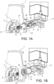
- FIG. 1A An example of a metal tank 1, or interrupting chamber, comprising a switch 10 according to an embodiment of the invention, is illustrated on figures 1A and 1B .
- the metal tank 1 is filled with a gas, for example SF 6 or another gas, for example comprising heptafluoroisobutyronitrile and/or heptafluoroisopropyl trifluoromethyl ketone (also named 2-butanone, 1,1,1,3,4,4,4-heptafluoro-3-(trifluoromethyl)- ( CAS No 756-12-7 )) and/or CO 2 and/or Oz and/or N 2 and/or an oxygenated compounds; for example said other gas can comprise both CO 2 and a fluorinated compound, for example heptafluoroisobutyronitrile and/or heptafluoroisopropyl trifluoromethyl ketone.
- a gas for example SF 6 or another gas, for example comprising heptafluoroisobutyronitrile and/or heptafluoroisopropyl trifluoromethyl ketone (also named 2-butanone, 1,1,1,3,4,4,4-heptaflu
- An outer part (a conductor forming a corona shield) 3 houses a stationary contact 5, which is itself in contact with an electrical conductor 7 (a conductor forming the inner part of the corona shield).
- Reference 31 is an electrically insulting part.
- An earthing switch 10 can be in contact with said stationary contact 5 ( figure 1A ), thereby connecting it to earth.
- the stationary contact 5 can comprise a plurality of fingers (they have a tulip shape) for example made of tungsten.
- both contacts are separated from each other ( figure 1B ), the stationary contact 5 being for example at a voltage of a few kV, for example between 2 kV and 30 kV.
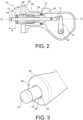
- the switch 10 is enclosed in a housing or enclosure 30 (which is fixed to the metal tank 1 and remains fixed with respect to it) and extends along an axis AA' (see figures 1A and 2 ).
- the housing or enclosure 30 is for example made of aluminium.
- the switch comprises a movable contact rod 12 mounted to move relative to the fixed contact 5 along said axis AA' with help of an actuation system 6, 8. It can move from a closed position ( figure 1A ), in which the electric current can flow through the switch (the contact 5 being earthed) and through lateral contacts 16 of the rod to an open position ( figure 1B ), in which the electric current between the fixed contact 5 and the rod 12 is interrupted and vice-versa.
- the lateral contacts 16 are made for example of a mixture of Copper and Chromium (Cu-Cr), without tungsten, they can have a tulip shape. They remain fixed with respect to the metal tank 1, the contact rod sliding in them. They are for example mounted on a flange or a collar 17 which is fixed in the housing 30. Openings 19 may be provided in the collar 17 in order to be able to inject gas in the rear part of the housing.
- a switch according to the invention comprises a moving contact made up of a rod 12, comprising an end 14 (a tip) usually made of copper and tungsten (Cu-W) and having preferably a rounded shape. It is for example electron-beam welded to the rest of the rod which is made of Cu-Cr.
- a cylinder 20 is fixed to the rod by securing means 27 (for example one or more rivet(s) or screw(s)) and partly surrounds the rod to form a cylindrical gas chamber 28.
- This gas or blowing chamber has a large volume, for example 0.64 I, when the system is closed ( figure 1A ) and a smaller volume, for example 0.034 I, when the system is open ( figure 1B and figure 2 ).
- a lip 24 extends from the cylinder 20 towards the rod 12, but its end 241 does not contact the rod so that it forms an outlet slot 22 with the rod.
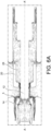
- the distance between the end 241 and the rod 12 (see thickness "e" on figure 4 ) and distance d1 (see figure 2 ) between the end of the cylinder and the end 14 of the rod 12 are chosen so that the gas escaping the chamber stays close to the pin (for example d1 is comprised between 10 mm and 60 mm and e can be comprised between 3 mm and 10 mm).
- the optimal parameters for each particular configuration can be found by means of experiments or by fluid simulations.
- the compressed gas contained in the blowing chamber 28 thus can escape (see the arrows on figure 4 ) through said slot 22, between the end 241 of the lip 24 and the lateral surface of the rod 12, when it is compressed by the cylinder during the opening of the switch, for example at a speed of between 1 m/s and 10 m/s.
- the compression begins with the beginning of the opening of the switch, which contributes to the efficiency of the quenching process.
- the cylinder 20 is made for example of aluminium or of a plastic material. It can slide in the housing 30.
- An insulating spacer 33 (which can be fixed to housing 30 and to tank 1) closes the gas chamber. Cylinder 20 slides over insulating spacer 33.
- the two contacts 5, 12 separate, for example at a speed between 1 m/s and 10 m/s, for example 5 m/s.
- a predetermined distance d (see figure 5 ) between the fixed contact 5 (which can be at a few kV, for example between 2 kV and 30 kV) and the end 14 of the rod, an arc 40 is formed, with a current of up to several hundreds of A, for example between 10 A and 500 A.
- the distance d is for example comprised between 1 cm and 5 cm, it is for example about 4 cm.
- a first position is illustrated on figure 6A , in which both contacts 5, 12 have just separated.
- the movable contact travels in the direction of the arrow at a speed of, for example, 5 m/s.
- the gas contained in the chamber 28 starts being compressed from the separation of both contacts.
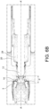
- a second position is illustrated on figure 6B , the distance d between both contacts 5, 12 is for example between 5 mm and 30 mm, for example about 25 mm.
- the compressed gas contained in the chamber 28 starts flowing along the rod 12 towards its end 14.
- the flow of gas is subject to the Coanda effect and follows the rounded shape of the end 14.
- Figure 6D shows a final position, in which the distance between both contacts 5, 12 is maximum (it is for example larger than 60 mm, for example about 90 mm).
- the actuation system 6, 8 (forming means for opening and closing the switch) comprises for example a rod 6 actuated at one of its ends by a lever 8 (see figures 1A , 2 , 5 ) mounted to pivot about an axis 81 (perpendicular to the axis AA' of the circuit-breaker).
- the other end of the rod 6 is also mounted in rotation on the rod 12 about an axis to move the rod 12 along the axis AA'.
- the actuation system converts the rotation of the axis 81 (driven by a mechanism not explained in detail) into a translation of the rod 12 along axis AA'.
- the length of the arms of the rod 6 and the lever 8 can be dimensioned according to the needs, in particular the expected timing of the arcing; for example lever 8 has a length of 108 mm and rod 6 a length of 69 mm.
- the GIS according to the invention comprises and operates in a gas, for example SF 6 ; alternatively, in order to reduce the greenhouse effects resulting from the use of SF 6 , the following gas may be used:
- the invention finds application in GIS which operate under a very high voltage (for example 400kV, more generally between 100 kV and 500 kV). But the invention is also applicable to higher voltages
Landscapes
- Engineering & Computer Science (AREA)
- Power Engineering (AREA)
- Circuit Breakers (AREA)
- Gas-Insulated Switchgears (AREA)
- Arc-Extinguishing Devices That Are Switches (AREA)
Abstract
- a movable contact rod (12), having an end (14);
- a cylinder (20), fixed to said contact and forming a gas chamber (28) around at least part of said contact rod, said gas chamber comprising an outlet (22) around said contact rod so that gas can flow along said contact rod (12) and its end (14) when it moves from a closed to an open position;
- means (6, 8) for actuating said contact rod between a closed and an open position.
Description
- The invention relates to the gas-insulated substations, commonly referred to as Gas-Insulated Substations (GISs).
- The invention relates particularly to fast earthing switches of this type of electrical equipment. Earthing switches make it possible to earth the electrical conductors or bars, depending on the operation of the electrical network running through the equipment or during maintenance operations of this last.
- More specifically, a switch comprises a contact rod which penetrates a conductor or bar and which is connected to the casing of the switch.
- A gas-Insulated Substation (GIS) is generally insulated using sulfur hexafluoride (SF6) in metal tanks filled with SF6 under pressure, at a service pressure of 0.4 megapascals (MPa) to 0.8 MPa, e.g. 0.7 MPa.
- Sulfur hexafluoride (SF6) being estimated to contribute to the greenhouse effect, it was recently replaced by other gases. In particular, a gas called g3 and comprising heptafluoroisobutyronitrile mixed with a dilution gas comprising carbon dioxide and a high content of oxygen is used in replacement of SF6. Such a new gas has a drastically reduced the environmental impact (more than 99% less gas global warming potential (GWP), Comparatively) and operates with no restriction under the same temperature range as SF6 products (down to -30°C).
- But it has been noticed that this new gas is more easily decomposed upon opening any fast earthing switch in a GIS implementing said gas. In particular, this gas is more easily ionized and does not recombine into the original gas. As a consequence, the arc does not stop.
- There is therefore the problem of limiting, and even stopping, as fast as possible, the arc during the opening of a fast earthing switch of a GIS, in particular a GIS implementing said g3 gas but also any other alternative gas.
- There is therefore the problem of finding a new earthing switch able to perform fast switching operations in a GIS, the GIS being filled with SF6 or alternatively with a gas comprising, for example heptafluoroisobutyronitrile and/or heptafluoroisopropyl trifluoromethyl ketone (also named 2-butanone, 1,1,1,3,4,4,4-heptafluoro-3-(trifluoromethyl)- (CAS No 756-12-7)) and/or CO2 and/or Oz and/or N2 and/or an oxygenated compounds; for example it can comprise both CO2 and a fluorinated compound, for example heptafluoroisobutyronitrile and/or heptafluoroisopropyl trifluoromethyl ketone.
- In order to solve the above problem, the inventors have found a solution to blow more efficiently the arc generated during opening a fast earthing switch.
- The invention first concerns an earthing switch for a GIS comprising:
- a movable contact rod;
- a cylinder, fixed to said contact and forming a gas chamber around at least part of said contact rod, said gas chamber comprising an outlet around said contact rod so that gas flows along said contact rod when it moves from a closed to an open position;
- means for actuating said contact rod between a closed and an open position.
- The flow of gas at the end portion of the contact rod reduces the temperature of the previously arced gas. The "cooling" of this zone restores the dielectric properties of the gas and the electric arc is interrupted.
- Said cylinder can have an end provided with a lip which extends from said cylinder towards the rod and which has an end separated from the rod, thereby forming an outlet slot with the rod.
- Said cylinder is for example made of aluminium or of a plastic material.
- Preferably, in a fast earthing switch according to the invention:
- a distance (d1) between and end of said cylinder and said end is for example between 10 mm and 60 mm;
- and/or said outlet has a thickness (e) for example between 3 mm and 10 mm.
- The invention also concerns a GIS comprising:
- a metal tank filled with a gas;
- an earthing switch according to the invention, as disclosed above or in this application.
- A GIS according to the invention can be filled with SF6,, but alternatively it can be filled with, or comprise, an alternative gas, for example comprising heptafluoroisobutyronitrile and/or heptafluoroisopropyl trifluoromethyl ketone (also named 2-butanone, 1,1,1,3,4,4,4-heptafluoro-3-(trifluoromethyl)- (CAS No 756-12-7)) and/or CO2 and/or O2 and/or N2 and/or an oxygenated compounds; for example it can comprise both CO2 and a fluorinated compound, for example heptafluoroisobutyronitrile and/or heptafluoroisopropyl trifluoromethyl ketone. Said alternative gas can decompose and generate much powder as explained above.
- The invention also concerns a method for opening an earthing switch of a GIS according to the invention, comprising:
- moving the movable contact rod with respect to the fixed contact, thereby separating the movable contact from the fixed contact;
- blowing a flow of gas along said rod, the gas flowing along the curved end of the contact, thereby quenching the arc.
- In a method according to the invention:
- said fixed contact is for example at a voltage between 2 kV and 30 kV after opening of the switch;
- and/or the rod moves at a speed comprised between 1m/s and 10 m/s during the separation of the movable contact rod from the fixed contact.
-
-
figures 1A and 1B shows an example of a Gas-Insulated Substation and a switch according to an embodiment of the invention; -
figures 2 and5 show an example of a switch according to the invention; -
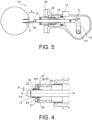
figure 3 shows an enlarged front view of a switch according to the invention; -
figure 4 illustrates a flow of gas flowing along a rod of a switch according to the invention; -
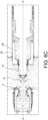
figures 6A- 6D show various steps of an opening phase of an earthing switch according to the invention. - An example of a metal tank 1, or interrupting chamber, comprising a
switch 10 according to an embodiment of the invention, is illustrated onfigures 1A and 1B . - The metal tank 1 is filled with a gas, for example SF6 or another gas, for example comprising heptafluoroisobutyronitrile and/or heptafluoroisopropyl trifluoromethyl ketone (also named 2-butanone, 1,1,1,3,4,4,4-heptafluoro-3-(trifluoromethyl)- (CAS No 756-12-7)) and/or CO2 and/or Oz and/or N2 and/or an oxygenated compounds; for example said other gas can comprise both CO2 and a fluorinated compound, for example heptafluoroisobutyronitrile and/or heptafluoroisopropyl trifluoromethyl ketone.
- An outer part (a conductor forming a corona shield) 3 houses a
stationary contact 5, which is itself in contact with an electrical conductor 7 (a conductor forming the inner part of the corona shield).Reference 31 is an electrically insulting part. - An
earthing switch 10 can be in contact with said stationary contact 5 (figure 1A ), thereby connecting it to earth. Thestationary contact 5 can comprise a plurality of fingers (they have a tulip shape) for example made of tungsten. - After an interruption, both contacts are separated from each other (
figure 1B ), thestationary contact 5 being for example at a voltage of a few kV, for example between 2 kV and 30 kV. - The
switch 10 is enclosed in a housing or enclosure 30 (which is fixed to the metal tank 1 and remains fixed with respect to it) and extends along an axis AA' (seefigures 1A and2 ). The housing orenclosure 30 is for example made of aluminium. - The switch comprises a
movable contact rod 12 mounted to move relative to the fixedcontact 5 along said axis AA' with help of anactuation system figure 1A ), in which the electric current can flow through the switch (thecontact 5 being earthed) and throughlateral contacts 16 of the rod to an open position (figure 1B ), in which the electric current between thefixed contact 5 and therod 12 is interrupted and vice-versa. Thelateral contacts 16 are made for example of a mixture of Copper and Chromium (Cu-Cr), without tungsten, they can have a tulip shape. They remain fixed with respect to the metal tank 1, the contact rod sliding in them. They are for example mounted on a flange or acollar 17 which is fixed in thehousing 30.Openings 19 may be provided in thecollar 17 in order to be able to inject gas in the rear part of the housing. - As can be seen on
figure 2 a switch according to the invention comprises a moving contact made up of arod 12, comprising an end 14 (a tip) usually made of copper and tungsten (Cu-W) and having preferably a rounded shape. It is for example electron-beam welded to the rest of the rod which is made of Cu-Cr. - A
cylinder 20 is fixed to the rod by securing means 27 (for example one or more rivet(s) or screw(s)) and partly surrounds the rod to form acylindrical gas chamber 28. This gas or blowing chamber has a large volume, for example 0.64 I, when the system is closed (figure 1A ) and a smaller volume, for example 0.034 I, when the system is open (figure 1B andfigure 2 ). Alip 24 extends from thecylinder 20 towards therod 12, but itsend 241 does not contact the rod so that it forms anoutlet slot 22 with the rod. The distance between theend 241 and the rod 12 (see thickness "e" onfigure 4 ) and distance d1 (seefigure 2 ) between the end of the cylinder and theend 14 of therod 12 are chosen so that the gas escaping the chamber stays close to the pin (for example d1 is comprised between 10 mm and 60 mm and e can be comprised between 3 mm and 10 mm). The optimal parameters for each particular configuration can be found by means of experiments or by fluid simulations. - The compressed gas contained in the blowing
chamber 28 thus can escape (see the arrows onfigure 4 ) through saidslot 22, between theend 241 of thelip 24 and the lateral surface of therod 12, when it is compressed by the cylinder during the opening of the switch, for example at a speed of between 1 m/s and 10 m/s. Actually the compression begins with the beginning of the opening of the switch, which contributes to the efficiency of the quenching process. - The
cylinder 20 is made for example of aluminium or of a plastic material. It can slide in thehousing 30. An insulating spacer 33 (which can be fixed tohousing 30 and to tank 1) closes the gas chamber.Cylinder 20 slides over insulatingspacer 33. - During the opening procedure of the
switch 10, the twocontacts figure 5 ) between the fixed contact 5 (which can be at a few kV, for example between 2 kV and 30 kV) and theend 14 of the rod, anarc 40 is formed, with a current of up to several hundreds of A, for example between 10 A and 500 A. The distance d is for example comprised between 1 cm and 5 cm, it is for example about 4 cm. - Due to the compression of the cool gas in the
gas chamber 28, a flow of this gas flows along the surface of therod 12 towards theend 14. The cool gas then flows along the roundedshaped end 14 due to the Coanda effect, which contributes to a very efficient quenching of the arc. Indeed, there is a sticking effect of the cool gas on theend 14 of the pin. The cool gas then arrives in the arcing zone to cool the arc and interrupts the current of the arc. - An example of an opening process of a switch according to the invention is more precisely illustrated on
Figures 6A-6D . The same references as above designate the same elements. - A first position is illustrated on
figure 6A , in which bothcontacts chamber 28 starts being compressed from the separation of both contacts. - A second position is illustrated on
figure 6B , the distance d between bothcontacts chamber 28 starts flowing along therod 12 towards itsend 14. The flow of gas is subject to the Coanda effect and follows the rounded shape of theend 14. - In a third position illustrated on
figure 6C , the distance between bothcontacts figure 6B . The speed of the gas which flows out of the blowing chamber has also increased (because of the reduction of the volume of the blowing chamber), it is for example around 20 m/s; this gas comes to the end of the rod and then to the arc ignition point. An arc is generated between thecontacts end portion 14 reduces the temperature of the previously arced gas in this zone. The "cooling" of this zone restores the dielectric properties of the gas and the electric arc is interrupted. -
Figure 6D shows a final position, in which the distance between bothcontacts - The
actuation system 6, 8 (forming means for opening and closing the switch) comprises for example arod 6 actuated at one of its ends by a lever 8 (seefigures 1A ,2 ,5 ) mounted to pivot about an axis 81 (perpendicular to the axis AA' of the circuit-breaker). The other end of therod 6 is also mounted in rotation on therod 12 about an axis to move therod 12 along the axis AA'. In other words, the actuation system converts the rotation of the axis 81 (driven by a mechanism not explained in detail) into a translation of therod 12 along axis AA'. - The length of the arms of the
rod 6 and thelever 8 can be dimensioned according to the needs, in particular the expected timing of the arcing; forexample lever 8 has a length of 108 mm and rod 6 a length of 69 mm. - The GIS according to the invention comprises and operates in a gas, for example SF6; alternatively, in order to reduce the greenhouse effects resulting from the use of SF6, the following gas may be used:
- a gas comprising heptafluoroisobutyronitrile and/or heptafluoroisopropyl trifluoromethyl ketone (also named 2-butanone, 1,1,1,3,4,4,4-heptafluoro-3-(trifluoromethyl)- (CAS No 756-12-7)), possibly mixed with a gas or a dilution gas comprising at least CO2 and/O2 and/or N2 and/or and/or an oxygenated compound;
- or in a gas comprising at least COz and/O2 and/or N2 and/or an oxygenated compound.
- The invention finds application in GIS which operate under a very high voltage (for example 400kV, more generally between 100 kV and 500 kV). But the invention is also applicable to higher voltages
Claims (10)
- A fast earthing switch (10) for a GIS comprising:- a movable contact rod (12), having an end (14);- a cylinder (20), fixed to said contact and forming a gas chamber (28) around at least part of said contact rod, said gas chamber comprising an outlet (22) around said contact rod so that gas can flow along said contact rod (12) and its end (14) when it moves from a closed to an open position;- means (6, 8) for actuating said contact rod between a closed and an open position.
- A fast earthing switch (10) according to claim 1, said cylinder (20) having an end provided with a lip (24) which extends from said cylinder (20) towards the rod (12) and which has an end (241) which is separated from the rod (12), thereby forming an outlet slot (22) with the rod.
- A fast earthing switch (10) according to claim 1 or 2, said cylinder (20) being made of aluminium or of a plastic material.
- A fast earthing switch (10) according to any of claims 1 to 3, a distance (d1) between and end of said cylinder (20) and said end (14) being between 10 mm and 60 mm.
- A fast earthing switch (10) according to any of claims 1 to 4, said outlet (22) having a thickness (e) between 3 mm and 10 mm.
- A GIS comprising:- a metal tank (1) filled with a gas;- a fast earthing switch (10) according to any of claims 1 to 5.
- A GIS according to claim 6, said gas comprising SF6, or heptafluoroisobutyronitrile and/or heptafluoroisopropyl trifluoromethyl ketone (also named 2-butanone, 1,1,1,3,4,4,4-heptafluoro-3-(trifluoromethyl)- (CAS No 756-12-7)) and/or CO2 and/or O2 and/or N2 and/or an oxygenated compounds, for example said comprising both CO2 and a fluorinated compound, for example heptafluoroisobutyronitrile and/or heptafluoroisopropyl trifluoromethyl ketone.
- A method for opening an earthing switch (10) of a GIS according to claim 6 or 7, comprising:- separating the movable contact rod (12) from the fixed contact (5) of the GIS;- blowing a flow of gas along said rod, so that the gas flow follows the shape of the end (14) of the rod (12).
- A method according to claim 8, said fixed contact (5) being at a voltage between 3 kV and 30 kV after opening of the switch.
- A method according to claim 8 or 9, the rod moving at a speed comprised between 1m/s and 10 m/s during the separation of the movable contact rod (12) from the fixed contact (5).
Priority Applications (5)
| Application Number | Priority Date | Filing Date | Title |
|---|---|---|---|
| EP23305195.2A EP4418295A1 (en) | 2023-02-14 | 2023-02-14 | Fast earthing switch implementing the coanda effect |
| US18/439,956 US20240274384A1 (en) | 2023-02-14 | 2024-02-13 | Fast earthing switch implementing the coanda effect |
| JP2024019085A JP2024115535A (en) | 2023-02-14 | 2024-02-13 | High-speed earth switch using the Coanda effect |
| KR1020240021125A KR20240126843A (en) | 2023-02-14 | 2024-02-14 | Fast earthing switch implementing the coanda effect |
| CN202410180624.XA CN118507293A (en) | 2023-02-14 | 2024-02-18 | Fast grounding switch using coanda effect |
Applications Claiming Priority (1)
| Application Number | Priority Date | Filing Date | Title |
|---|---|---|---|
| EP23305195.2A EP4418295A1 (en) | 2023-02-14 | 2023-02-14 | Fast earthing switch implementing the coanda effect |
Publications (1)
| Publication Number | Publication Date |
|---|---|
| EP4418295A1 true EP4418295A1 (en) | 2024-08-21 |
Family
ID=85384664
Family Applications (1)
| Application Number | Title | Priority Date | Filing Date |
|---|---|---|---|
| EP23305195.2A Pending EP4418295A1 (en) | 2023-02-14 | 2023-02-14 | Fast earthing switch implementing the coanda effect |
Country Status (5)
| Country | Link |
|---|---|
| US (1) | US20240274384A1 (en) |
| EP (1) | EP4418295A1 (en) |
| JP (1) | JP2024115535A (en) |
| KR (1) | KR20240126843A (en) |
| CN (1) | CN118507293A (en) |
Citations (4)
| Publication number | Priority date | Publication date | Assignee | Title |
|---|---|---|---|---|
| EP3422381A1 (en) * | 2017-06-29 | 2019-01-02 | ABB Schweiz AG | Gas-insulated load break switch and switchgear comprising a gas-insulated load break switch |
| EP3611745A1 (en) * | 2018-08-16 | 2020-02-19 | ABB Schweiz AG | Gas-insulated low- or medium-voltage load break switch |
| WO2021028138A1 (en) * | 2019-08-13 | 2021-02-18 | Siemens Energy Global GmbH & Co. KG | Electrical switching device |
| EP4105959A1 (en) * | 2021-06-16 | 2022-12-21 | General Electric Technology GmbH | Electrical connector comprising a first electrical contact and a mobile body moving axially at different speed |
Family Cites Families (7)
| Publication number | Priority date | Publication date | Assignee | Title |
|---|---|---|---|---|
| US4413166A (en) * | 1981-03-19 | 1983-11-01 | Westinghouse Electric Corp. | Disconnect switch |
| KR101771465B1 (en) * | 2011-07-25 | 2017-09-06 | 엘에스산전 주식회사 | Gas insulated switchgear |
| JP6053162B2 (en) * | 2013-06-18 | 2017-01-18 | 株式会社日立製作所 | Manufacturing method of puffer cylinder |
| EP3482408B1 (en) * | 2016-07-06 | 2023-06-07 | Hitachi Energy Switzerland AG | Fast earthing switch device for hv applications |
| JP6370518B1 (en) * | 2017-09-28 | 2018-08-08 | 三菱電機株式会社 | Switchgear |
| KR102135381B1 (en) * | 2018-10-30 | 2020-07-17 | 엘에스일렉트릭(주) | High Speed Earthing Switch of Gas Insulated Switchgear |
| KR102171601B1 (en) * | 2019-01-04 | 2020-10-29 | 효성중공업 주식회사 | Electrode driving apparatus for gas insulated switchgear |
-
2023
- 2023-02-14 EP EP23305195.2A patent/EP4418295A1/en active Pending
-
2024
- 2024-02-13 US US18/439,956 patent/US20240274384A1/en active Pending
- 2024-02-13 JP JP2024019085A patent/JP2024115535A/en active Pending
- 2024-02-14 KR KR1020240021125A patent/KR20240126843A/en active Pending
- 2024-02-18 CN CN202410180624.XA patent/CN118507293A/en active Pending
Patent Citations (4)
| Publication number | Priority date | Publication date | Assignee | Title |
|---|---|---|---|---|
| EP3422381A1 (en) * | 2017-06-29 | 2019-01-02 | ABB Schweiz AG | Gas-insulated load break switch and switchgear comprising a gas-insulated load break switch |
| EP3611745A1 (en) * | 2018-08-16 | 2020-02-19 | ABB Schweiz AG | Gas-insulated low- or medium-voltage load break switch |
| WO2021028138A1 (en) * | 2019-08-13 | 2021-02-18 | Siemens Energy Global GmbH & Co. KG | Electrical switching device |
| EP4105959A1 (en) * | 2021-06-16 | 2022-12-21 | General Electric Technology GmbH | Electrical connector comprising a first electrical contact and a mobile body moving axially at different speed |
Non-Patent Citations (1)
| Title |
|---|
| CAS , no. 756-12-7 |
Also Published As
| Publication number | Publication date |
|---|---|
| CN118507293A (en) | 2024-08-16 |
| JP2024115535A (en) | 2024-08-26 |
| KR20240126843A (en) | 2024-08-21 |
| US20240274384A1 (en) | 2024-08-15 |
Similar Documents
| Publication | Publication Date | Title |
|---|---|---|
| EP3477675B1 (en) | Gas-insulated medium-voltage switch with shield device | |
| US3814883A (en) | Gas-blast circuit interrupter with insulating arc shield | |
| US10991528B2 (en) | Gas-insulated load break switch and switchgear comprising a gas-insulated load break switch | |
| US12482618B2 (en) | Electrical switching device | |
| US20250372963A1 (en) | Sf6 free gas insulated disconnector with fully closed arcing chamber actuated by rod mechanism | |
| US8901447B2 (en) | Circuit breaker with parallel rated current paths | |
| WO2018145969A1 (en) | Arc splitter plate | |
| US20240274384A1 (en) | Fast earthing switch implementing the coanda effect | |
| EP3611745B1 (en) | Gas-insulated low- or medium-voltage load break switch | |
| EP4661045A1 (en) | Sf6 free gas insulated disconnector with fully closed arcing chamber and spring actuation | |
| US20240258049A1 (en) | Sf6 free gas insulated disconnector with limited arcing volume | |
| EP2827353A1 (en) | Electrical switching device | |
| EP4738416A1 (en) | Circuit-breaker | |
| EP4117006B1 (en) | Gas-insulated high or medium voltage circuit breaker | |
| JP7539363B2 (en) | Power Switchgear | |
| US20250385059A1 (en) | High voltage circuit-breaker having an optimized contacts design | |
| Jones | The impact of SF6 upon power switchgear technology. Part 1: SF6 switch implications | |
| JPH05250967A (en) | Puffer type gas circuit breaker | |
| CN103155317A (en) | Earthing switch and high-voltage transformer substation comprising such a device |
Legal Events
| Date | Code | Title | Description |
|---|---|---|---|
| PUAI | Public reference made under article 153(3) epc to a published international application that has entered the european phase |
Free format text: ORIGINAL CODE: 0009012 |
|
| STAA | Information on the status of an ep patent application or granted ep patent |
Free format text: STATUS: THE APPLICATION HAS BEEN PUBLISHED |
|
| AK | Designated contracting states |
Kind code of ref document: A1 Designated state(s): AL AT BE BG CH CY CZ DE DK EE ES FI FR GB GR HR HU IE IS IT LI LT LU LV MC ME MK MT NL NO PL PT RO RS SE SI SK SM TR |
|
| STAA | Information on the status of an ep patent application or granted ep patent |
Free format text: STATUS: REQUEST FOR EXAMINATION WAS MADE |
|
| 17P | Request for examination filed |
Effective date: 20250219 |
|
| RAP3 | Party data changed (applicant data changed or rights of an application transferred) |
Owner name: GE VERNOVA TECHNOLOGY GMBH |
|
| GRAP | Despatch of communication of intention to grant a patent |
Free format text: ORIGINAL CODE: EPIDOSNIGR1 |
|
| STAA | Information on the status of an ep patent application or granted ep patent |
Free format text: STATUS: GRANT OF PATENT IS INTENDED |
|
| INTG | Intention to grant announced |
Effective date: 20260526 |