EP4418261A1 - Signal processing method and apparatus, and storage medium and vehicle - Google Patents
Signal processing method and apparatus, and storage medium and vehicle Download PDFInfo
- Publication number
- EP4418261A1 EP4418261A1 EP21961111.8A EP21961111A EP4418261A1 EP 4418261 A1 EP4418261 A1 EP 4418261A1 EP 21961111 A EP21961111 A EP 21961111A EP 4418261 A1 EP4418261 A1 EP 4418261A1
- Authority
- EP
- European Patent Office
- Prior art keywords
- audio signal
- processing
- parameter
- signal
- processing manner
- Prior art date
- Legal status (The legal status is an assumption and is not a legal conclusion. Google has not performed a legal analysis and makes no representation as to the accuracy of the status listed.)
- Granted
Links
Images




Classifications
-
- G—PHYSICS
- G10—MUSICAL INSTRUMENTS; ACOUSTICS
- G10K—SOUND-PRODUCING DEVICES; METHODS OR DEVICES FOR PROTECTING AGAINST, OR FOR DAMPING, NOISE OR OTHER ACOUSTIC WAVES IN GENERAL; ACOUSTICS NOT OTHERWISE PROVIDED FOR
- G10K11/00—Methods or devices for transmitting, conducting or directing sound in general; Methods or devices for protecting against, or for damping, noise or other acoustic waves in general
- G10K11/16—Methods or devices for protecting against, or for damping, noise or other acoustic waves in general
- G10K11/175—Methods or devices for protecting against, or for damping, noise or other acoustic waves in general using interference effects; Masking sound
- G10K11/178—Methods or devices for protecting against, or for damping, noise or other acoustic waves in general using interference effects; Masking sound by electro-acoustically regenerating the original acoustic waves in anti-phase
- G10K11/1785—Methods, e.g. algorithms; Devices
- G10K11/17853—Methods, e.g. algorithms; Devices of the filter
- G10K11/17854—Methods, e.g. algorithms; Devices of the filter the filter being an adaptive filter
-
- G—PHYSICS
- G10—MUSICAL INSTRUMENTS; ACOUSTICS
- G10K—SOUND-PRODUCING DEVICES; METHODS OR DEVICES FOR PROTECTING AGAINST, OR FOR DAMPING, NOISE OR OTHER ACOUSTIC WAVES IN GENERAL; ACOUSTICS NOT OTHERWISE PROVIDED FOR
- G10K11/00—Methods or devices for transmitting, conducting or directing sound in general; Methods or devices for protecting against, or for damping, noise or other acoustic waves in general
- G10K11/16—Methods or devices for protecting against, or for damping, noise or other acoustic waves in general
- G10K11/175—Methods or devices for protecting against, or for damping, noise or other acoustic waves in general using interference effects; Masking sound
-
- G—PHYSICS
- G10—MUSICAL INSTRUMENTS; ACOUSTICS
- G10K—SOUND-PRODUCING DEVICES; METHODS OR DEVICES FOR PROTECTING AGAINST, OR FOR DAMPING, NOISE OR OTHER ACOUSTIC WAVES IN GENERAL; ACOUSTICS NOT OTHERWISE PROVIDED FOR
- G10K11/00—Methods or devices for transmitting, conducting or directing sound in general; Methods or devices for protecting against, or for damping, noise or other acoustic waves in general
- G10K11/16—Methods or devices for protecting against, or for damping, noise or other acoustic waves in general
- G10K11/175—Methods or devices for protecting against, or for damping, noise or other acoustic waves in general using interference effects; Masking sound
- G10K11/178—Methods or devices for protecting against, or for damping, noise or other acoustic waves in general using interference effects; Masking sound by electro-acoustically regenerating the original acoustic waves in anti-phase
- G10K11/1781—Methods or devices for protecting against, or for damping, noise or other acoustic waves in general using interference effects; Masking sound by electro-acoustically regenerating the original acoustic waves in anti-phase characterised by the analysis of input or output signals, e.g. frequency range, modes, transfer functions
- G10K11/17813—Methods or devices for protecting against, or for damping, noise or other acoustic waves in general using interference effects; Masking sound by electro-acoustically regenerating the original acoustic waves in anti-phase characterised by the analysis of input or output signals, e.g. frequency range, modes, transfer functions characterised by the analysis of the acoustic paths, e.g. estimating, calibrating or testing of transfer functions or cross-terms
-
- G—PHYSICS
- G10—MUSICAL INSTRUMENTS; ACOUSTICS
- G10K—SOUND-PRODUCING DEVICES; METHODS OR DEVICES FOR PROTECTING AGAINST, OR FOR DAMPING, NOISE OR OTHER ACOUSTIC WAVES IN GENERAL; ACOUSTICS NOT OTHERWISE PROVIDED FOR
- G10K11/00—Methods or devices for transmitting, conducting or directing sound in general; Methods or devices for protecting against, or for damping, noise or other acoustic waves in general
- G10K11/16—Methods or devices for protecting against, or for damping, noise or other acoustic waves in general
- G10K11/175—Methods or devices for protecting against, or for damping, noise or other acoustic waves in general using interference effects; Masking sound
- G10K11/178—Methods or devices for protecting against, or for damping, noise or other acoustic waves in general using interference effects; Masking sound by electro-acoustically regenerating the original acoustic waves in anti-phase
- G10K11/1781—Methods or devices for protecting against, or for damping, noise or other acoustic waves in general using interference effects; Masking sound by electro-acoustically regenerating the original acoustic waves in anti-phase characterised by the analysis of input or output signals, e.g. frequency range, modes, transfer functions
- G10K11/17821—Methods or devices for protecting against, or for damping, noise or other acoustic waves in general using interference effects; Masking sound by electro-acoustically regenerating the original acoustic waves in anti-phase characterised by the analysis of input or output signals, e.g. frequency range, modes, transfer functions characterised by the analysis of the input signals only
- G10K11/17823—Reference signals, e.g. ambient acoustic environment
-
- G—PHYSICS
- G10—MUSICAL INSTRUMENTS; ACOUSTICS
- G10K—SOUND-PRODUCING DEVICES; METHODS OR DEVICES FOR PROTECTING AGAINST, OR FOR DAMPING, NOISE OR OTHER ACOUSTIC WAVES IN GENERAL; ACOUSTICS NOT OTHERWISE PROVIDED FOR
- G10K11/00—Methods or devices for transmitting, conducting or directing sound in general; Methods or devices for protecting against, or for damping, noise or other acoustic waves in general
- G10K11/16—Methods or devices for protecting against, or for damping, noise or other acoustic waves in general
- G10K11/175—Methods or devices for protecting against, or for damping, noise or other acoustic waves in general using interference effects; Masking sound
- G10K11/178—Methods or devices for protecting against, or for damping, noise or other acoustic waves in general using interference effects; Masking sound by electro-acoustically regenerating the original acoustic waves in anti-phase
- G10K11/1783—Methods or devices for protecting against, or for damping, noise or other acoustic waves in general using interference effects; Masking sound by electro-acoustically regenerating the original acoustic waves in anti-phase handling or detecting of non-standard events or conditions, e.g. changing operating modes under specific operating conditions
- G10K11/17837—Methods or devices for protecting against, or for damping, noise or other acoustic waves in general using interference effects; Masking sound by electro-acoustically regenerating the original acoustic waves in anti-phase handling or detecting of non-standard events or conditions, e.g. changing operating modes under specific operating conditions by retaining part of the ambient acoustic environment, e.g. speech or alarm signals that the user needs to hear
-
- G—PHYSICS
- G10—MUSICAL INSTRUMENTS; ACOUSTICS
- G10K—SOUND-PRODUCING DEVICES; METHODS OR DEVICES FOR PROTECTING AGAINST, OR FOR DAMPING, NOISE OR OTHER ACOUSTIC WAVES IN GENERAL; ACOUSTICS NOT OTHERWISE PROVIDED FOR
- G10K11/00—Methods or devices for transmitting, conducting or directing sound in general; Methods or devices for protecting against, or for damping, noise or other acoustic waves in general
- G10K11/16—Methods or devices for protecting against, or for damping, noise or other acoustic waves in general
- G10K11/175—Methods or devices for protecting against, or for damping, noise or other acoustic waves in general using interference effects; Masking sound
- G10K11/178—Methods or devices for protecting against, or for damping, noise or other acoustic waves in general using interference effects; Masking sound by electro-acoustically regenerating the original acoustic waves in anti-phase
- G10K11/1785—Methods, e.g. algorithms; Devices
- G10K11/17857—Geometric disposition, e.g. placement of microphones
-
- G—PHYSICS
- G10—MUSICAL INSTRUMENTS; ACOUSTICS
- G10K—SOUND-PRODUCING DEVICES; METHODS OR DEVICES FOR PROTECTING AGAINST, OR FOR DAMPING, NOISE OR OTHER ACOUSTIC WAVES IN GENERAL; ACOUSTICS NOT OTHERWISE PROVIDED FOR
- G10K11/00—Methods or devices for transmitting, conducting or directing sound in general; Methods or devices for protecting against, or for damping, noise or other acoustic waves in general
- G10K11/16—Methods or devices for protecting against, or for damping, noise or other acoustic waves in general
- G10K11/175—Methods or devices for protecting against, or for damping, noise or other acoustic waves in general using interference effects; Masking sound
- G10K11/178—Methods or devices for protecting against, or for damping, noise or other acoustic waves in general using interference effects; Masking sound by electro-acoustically regenerating the original acoustic waves in anti-phase
- G10K11/1787—General system configurations
- G10K11/17873—General system configurations using a reference signal without an error signal, e.g. pure feedforward
-
- G—PHYSICS
- G10—MUSICAL INSTRUMENTS; ACOUSTICS
- G10K—SOUND-PRODUCING DEVICES; METHODS OR DEVICES FOR PROTECTING AGAINST, OR FOR DAMPING, NOISE OR OTHER ACOUSTIC WAVES IN GENERAL; ACOUSTICS NOT OTHERWISE PROVIDED FOR
- G10K11/00—Methods or devices for transmitting, conducting or directing sound in general; Methods or devices for protecting against, or for damping, noise or other acoustic waves in general
- G10K11/16—Methods or devices for protecting against, or for damping, noise or other acoustic waves in general
- G10K11/175—Methods or devices for protecting against, or for damping, noise or other acoustic waves in general using interference effects; Masking sound
- G10K11/178—Methods or devices for protecting against, or for damping, noise or other acoustic waves in general using interference effects; Masking sound by electro-acoustically regenerating the original acoustic waves in anti-phase
- G10K11/1787—General system configurations
- G10K11/17879—General system configurations using both a reference signal and an error signal
- G10K11/17881—General system configurations using both a reference signal and an error signal the reference signal being an acoustic signal, e.g. recorded with a microphone
-
- G—PHYSICS
- G10—MUSICAL INSTRUMENTS; ACOUSTICS
- G10K—SOUND-PRODUCING DEVICES; METHODS OR DEVICES FOR PROTECTING AGAINST, OR FOR DAMPING, NOISE OR OTHER ACOUSTIC WAVES IN GENERAL; ACOUSTICS NOT OTHERWISE PROVIDED FOR
- G10K11/00—Methods or devices for transmitting, conducting or directing sound in general; Methods or devices for protecting against, or for damping, noise or other acoustic waves in general
- G10K11/16—Methods or devices for protecting against, or for damping, noise or other acoustic waves in general
- G10K11/175—Methods or devices for protecting against, or for damping, noise or other acoustic waves in general using interference effects; Masking sound
- G10K11/178—Methods or devices for protecting against, or for damping, noise or other acoustic waves in general using interference effects; Masking sound by electro-acoustically regenerating the original acoustic waves in anti-phase
- G10K11/1787—General system configurations
- G10K11/17885—General system configurations additionally using a desired external signal, e.g. pass-through audio such as music or speech
-
- G—PHYSICS
- G10—MUSICAL INSTRUMENTS; ACOUSTICS
- G10K—SOUND-PRODUCING DEVICES; METHODS OR DEVICES FOR PROTECTING AGAINST, OR FOR DAMPING, NOISE OR OTHER ACOUSTIC WAVES IN GENERAL; ACOUSTICS NOT OTHERWISE PROVIDED FOR
- G10K2210/00—Details of active noise control [ANC] covered by G10K11/178 but not provided for in any of its subgroups
- G10K2210/10—Applications
- G10K2210/108—Communication systems, e.g. where useful sound is kept and noise is cancelled
- G10K2210/1081—Earphones, e.g. for telephones, ear protectors or headsets
-
- G—PHYSICS
- G10—MUSICAL INSTRUMENTS; ACOUSTICS
- G10K—SOUND-PRODUCING DEVICES; METHODS OR DEVICES FOR PROTECTING AGAINST, OR FOR DAMPING, NOISE OR OTHER ACOUSTIC WAVES IN GENERAL; ACOUSTICS NOT OTHERWISE PROVIDED FOR
- G10K2210/00—Details of active noise control [ANC] covered by G10K11/178 but not provided for in any of its subgroups
- G10K2210/10—Applications
- G10K2210/128—Vehicles
- G10K2210/1282—Automobiles
-
- G—PHYSICS
- G10—MUSICAL INSTRUMENTS; ACOUSTICS
- G10K—SOUND-PRODUCING DEVICES; METHODS OR DEVICES FOR PROTECTING AGAINST, OR FOR DAMPING, NOISE OR OTHER ACOUSTIC WAVES IN GENERAL; ACOUSTICS NOT OTHERWISE PROVIDED FOR
- G10K2210/00—Details of active noise control [ANC] covered by G10K11/178 but not provided for in any of its subgroups
- G10K2210/30—Means
- G10K2210/301—Computational
- G10K2210/3012—Algorithms
-
- G—PHYSICS
- G10—MUSICAL INSTRUMENTS; ACOUSTICS
- G10K—SOUND-PRODUCING DEVICES; METHODS OR DEVICES FOR PROTECTING AGAINST, OR FOR DAMPING, NOISE OR OTHER ACOUSTIC WAVES IN GENERAL; ACOUSTICS NOT OTHERWISE PROVIDED FOR
- G10K2210/00—Details of active noise control [ANC] covered by G10K11/178 but not provided for in any of its subgroups
- G10K2210/30—Means
- G10K2210/301—Computational
- G10K2210/3028—Filtering, e.g. Kalman filters or special analogue or digital filters
Definitions
- This application relates to the signal processing field, and in particular, to a signal processing method and apparatus, a storage medium, and a vehicle.
- Vehicles in a high-speed driving process usually have relatively strong noise.
- the noise includes road noise generated through interaction between a tire and the ground and between a suspension and a body, wind noise, environmental noise, and the like. This seriously affects a comfort degree of an occupant.
- Energy of noise perceived by people can be reduced by using a noise reduction method, so that noise interference to people can be reduced.
- passive noise reduction is to reduce vehicle noise in a physical noise reduction manner.
- Active noise reduction generally uses an active noise cancellation (active noise cancellation, ANC) technology to generate, by using a speaker, an audio signal that suppresses a noise signal. After the noise signal meets and superimposes on the noise suppression signal, the noise signal and the noise suppression signal are neutralized to cancel each other, so that a purpose of noise reduction is achieved.
- active noise cancellation active noise cancellation
- a filter In the active noise reduction method, a filter is generally applicable only to noise reduction in a single working condition. Because a body structure of an actual vehicle is complex and a working condition is unstable, a real-time adjustment capability in actual application is relatively poor, quick noise reduction cannot be implemented, and a state in which a noise reduction amount is relatively large cannot be stabilized. Therefore, a noise reduction solution with a stronger real-time adjustment capability and a better noise reduction effect is urgently required.
- a signal processing method and apparatus a storage medium, and a vehicle are provided.
- an embodiment of this application provides a signal processing method.
- the method includes: receiving a first audio signal that is collected by one or more first sensors and that is at a noise source; receiving a second audio signal that is collected by one or more second sensors and that is at a human ear, where the first audio signal and the second audio signal are used to determine a parameter for processing the first audio signal in a first processing manner; and sending a third audio signal determined after the first audio signal is processed in the first processing manner, where the third audio signal indicates a speaker to emit a sound wave, and the sound wave is used to cancel noise at the human ear.
- real-time parameter adjustment is performed by using the second audio signal collected at the human ear.
- a current noise reduction state may be considered, and the parameter is adjusted based on the current noise reduction state.
- the first audio signal is processed by using an adjusted parameter to obtain the third audio signal, to indicate the speaker to emit the sound wave to cancel the noise, so that quicker noise reduction can be implemented, a noise reduction amount is larger, a noise reduction effect is better. This improves a comfort degree of an occupant.
- the method further includes: processing the first audio signal in a second processing manner to determine a fourth audio signal, where the second processing manner indicates a transmission manner in which the sound wave is transmitted from the speaker to the second sensor; determining a fifth audio signal based on the second audio signal and an audio signal that is obtained after the third audio signal is processed in the second processing manner; and determining, based on the fourth audio signal and the fifth audio signal, the parameter for processing the first audio signal in the first processing manner.
- the fourth audio signal is determined by estimating the transmission manner of transmission from the speaker to the second sensor, so that a transmission process of the first audio signal is considered.
- the fifth audio signal is obtained through reconstruction, so that initial noise heard by the occupant before noise reduction may be obtained through calculation.
- the parameter is adjusted with reference to the fourth audio signal and the fifth audio signal, so that a corresponding sound wave emitted by the speaker as indicated by an adjusted parameter can better cancel the noise. In this way, a larger noise reduction amount is obtained.
- the parameter may be adjusted in a timely manner through real-time calculation of the parameter based on the two, so that a noise reduction state can be restored more quickly when interference occurs, and robustness is higher. In this way, a better noise reduction effect is obtained.
- the determining, based on the fourth audio signal and the fifth audio signal, the parameter for processing the first audio signal in the first processing manner includes: determining, based on an autocorrelation matrix of the fourth audio signal and a cross-correlation matrix of the fourth audio signal and the fifth audio signal, the parameter for processing the first audio signal in the first processing manner.
- an autocorrelation degree of the fourth audio signal and a cross-correlation degree of the fourth audio signal and the fifth audio signal may be considered in a parameter adjustment process, so that a better noise reduction effect is implemented.
- the determining, based on an autocorrelation matrix of the fourth audio signal and a cross-correlation matrix of the fourth audio signal and the fifth audio signal, the parameter for processing the first audio signal in the first processing manner includes: determining a change direction of the parameter based on the autocorrelation matrix, the cross-correlation matrix, and a parameter at a previous moment; and determining a parameter at a current moment based on one or more of the following: the parameter at the previous moment, a signal length during processing in the first processing manner, the change direction of the parameter, and a change amplitude of the parameter.
- the parameter at the current moment is determined at each moment, so that a large noise reduction amount is stabilized and quick noise reduction is implemented, noise caused by a sudden change of a filter as a consequence of untimely parameter update can be avoided, and a comfort degree of experience of an occupant is improved.
- the processing the first audio signal in a second processing manner to determine a fourth audio signal includes: processing, in the second processing manner at an interval of a predetermined window moving distance, the first audio signal of a predetermined window length, to determine the fourth audio signal; and the determining a fifth audio signal based on the second audio signal and an audio signal that is obtained after the third audio signal is processed in the second processing manner includes: determining, at an interval of the predetermined window moving distance, the fifth audio signal based on the second audio signal of the predetermined window length and the audio signal that is obtained after the third audio signal is processed in the second processing manner.
- calculation may be performed by using a predetermined window, so that the fourth audio signal and the fifth audio signal do not need to be determined point by point. This reduces a calculation amount.
- the method further includes: determining a noise reduction amount based on the second audio signal and the fifth audio signal; and adjusting, based on the noise reduction amount, one or more of the following: the change amplitude of the parameter, the signal length during processing in the first processing manner, the predetermined window moving distance, and the predetermined window length.
- the noise reduction amount is calculated, and one or more of the following is adjusted based on the noise reduction amount: the change amplitude of the parameter, the signal length, the predetermined window moving distance, and the predetermined window length, so that different noise reduction environments and states can be adapted to in a noise reduction process. In this way, a better noise reduction effect is achieved and user experience is improved.
- the first processing manner is Wiener filtering.
- an embodiment of this application provides a signal processing apparatus.
- the apparatus includes: a first receiving module, configured to receive a first audio signal that is collected by one or more first sensors and that is at a noise source; a second receiving module, configured to receive a second audio signal that is collected by one or more second sensors and that is at a human ear, where the first audio signal and the second audio signal are used to determine a parameter for processing the first audio signal in a first processing manner; and a sending module, configured to send a third audio signal determined after the first audio signal is processed in the first processing manner, where the third audio signal indicates a speaker to emit a sound wave, and the sound wave is used to cancel noise at the human ear.
- the apparatus further includes: a first determining module, configured to process the first audio signal in a second processing manner to determine a fourth audio signal, where the second processing manner indicates a transmission manner in which the sound wave is transmitted from the speaker to the second sensor; a second determining module, configured to determine a fifth audio signal based on the second audio signal and an audio signal that is obtained after the third audio signal is processed in the second processing manner; and a third determining module, configured to determine, based on the fourth audio signal and the fifth audio signal, the parameter for processing the first audio signal in the first processing manner.
- the third determining module is configured to: determine, based on an autocorrelation matrix of the fourth audio signal and a cross-correlation matrix of the fourth audio signal and the fifth audio signal, the parameter for processing the first audio signal in the first processing manner.
- the determining, based on an autocorrelation matrix of the fourth audio signal and a cross-correlation matrix of the fourth audio signal and the fifth audio signal, the parameter for processing the first audio signal in the first processing manner includes: determining a change direction of the parameter based on the autocorrelation matrix, the cross-correlation matrix, and a parameter at a previous moment; and determining a parameter at a current moment based on one or more of the following: the parameter at the previous moment, a signal length during processing in the first processing manner, the change direction of the parameter, and a change amplitude of the parameter.
- the first determining module is configured to: process, in the second processing manner at an interval of a predetermined window moving distance, the first audio signal of a predetermined window length, to determine the fourth audio signal; and the second determining module is configured to: determine, at an interval of the predetermined window moving distance, the fifth audio signal based on the second audio signal of the predetermined window length and the audio signal that is obtained after the third audio signal is processed in the second processing manner.
- the apparatus further includes: a fourth determining module, configured to determine a noise reduction amount based on the second audio signal and the fifth audio signal; and an adjustment module, configured to adjust, based on the noise reduction amount, one or more of the following: the change amplitude of the parameter, the signal length during processing in the first processing manner, the predetermined window moving distance, and the predetermined window length.
- the first processing manner is Wiener filtering.
- an embodiment of this application provides a signal processing apparatus, where the apparatus includes a processor and a memory, the memory is configured to store a program, and the processor is configured to execute the program stored in the memory, to enable the apparatus to implement the signal processing method according to any one of the first aspect or the possible implementations of the first aspect.
- an embodiment of this application provides a terminal device.
- the terminal device may perform the signal processing method according to any one of the first aspect or the possible implementations of the first aspect.
- an embodiment of this application provides a computer-readable storage medium, where the computer-readable storage medium stores program instructions, and when the program instructions are executed by a computer, the computer is enabled to implement the method according to any one of the first aspect or the possible implementations of the first aspect.
- a sixth aspect of this application provides a computer program product that includes program instructions.
- the program instructions When the program instructions are executed by a computer, the computer is enabled to implement the signal processing method according to any one of the first aspect or the possible implementations of the first aspect.
- an embodiment of this application provides a vehicle, where the vehicle includes a processor, and the processor is configured to perform the signal processing method according to any one of the first aspect or the possible implementations of the first aspect.
- example herein means “used as an example, embodiment or illustration”. Any embodiment described as an “example” herein is not necessarily explained as being superior or better than other embodiments.
- FIG. 1 is a schematic diagram of an application scenario according to an embodiment of this application.
- a signal processing method in this embodiment of this application may be used to reduce noise heard by an occupant in a vehicle.
- a signal processing system in this embodiment of this application may be disposed in a vehicle, and the signal processing system includes a speaker, a sensor, and a processor.
- the speaker may be configured to emit a sound wave corresponding to an audio signal, to cancel noise near a human ear of the occupant, so that noise heard by the occupant in the vehicle is reduced.
- the sensor may include a first sensor and a second sensor.
- the first sensors may include an accelerometer, an in-vehicle radar (for example, a millimeter-wave radar, a lidar, or an ultrasonic radar), a rainfall sensor, a camera, a vehicle posture sensor (for example, a gyroscope), an inertial measurement unit (inertial measurement unit, IMU), and the like.
- the first sensor may be disposed near a noise source in the vehicle, and is configured to collect a reference signal.
- the reference signal may indicate noise near the noise source.
- the reference signal may include an acceleration signal collected by the accelerometer. Because the acceleration signal is proportional to a vibration amplitude of the vehicle, a noise magnitude near the noise source is determined by using the acceleration signal.
- the second sensor may include a microphone.
- the second sensor may be disposed near the human ear of the occupant in the vehicle, and is configured to collect a residual signal.
- the residual signal may indicate residual noise heard by the occupant in the vehicle after the sound wave emitted by the speaker cancels noise near the human ear.
- there may be a plurality of occupants in the vehicle, and a plurality of second sensors may be disposed respectively for the plurality of occupants to collect corresponding residual signals.
- the processor may be built into an in-vehicle infotainment (or an audio system) in the vehicle as an in-vehicle computing unit, for example, a digital signal processing (digital signal processor, DSP) chip.
- the processor may perform calculation based on a signal collected by the sensor, to determine the audio signal.
- the processor may alternatively be disposed outside a cloud server.
- the server and the vehicle may communicate in a wireless connection manner, for example, may communicate by using mobile communication technologies such as 2G/3G/4G/5G and in wireless communication manner, for example, Wi-Fi, Bluetooth, frequency modulation (frequency modulation, FM), radio modem, or satellite communication.
- the server may collect, by using communication between the vehicle and the server, the signal collected by the sensor to perform calculation, and send a calculation result back to the corresponding vehicle.
- the signal processing system in this embodiment of this application may further include a preamplifier and a power amplifier.
- the preamplifier may be configured to amplify the residual signal collected by the second sensor to a specific level range
- the power amplifier may be configured to amplify the audio signal to drive the speaker to emit a corresponding sound wave.
- the signal processing method in this embodiment of this application in a process of processing the reference signal to determine the audio signal to perform active noise reduction, the residual signal is further used to adjust a parameter used during processing, so that real-time adjustment can be performed based on a current noise reduction effect, and the audio signal can be dynamically changed. In this way, a larger noise reduction amount can be obtained by canceling a noise signal at the human ear with the dynamically adjusted audio signal, quick noise reduction may be implemented, and a better noise reduction effect is obtained.
- FIG. 2 and FIG. 3 uses FIG. 2 and FIG. 3 as examples to describe in detail the signal processing method in embodiments of this application based on the foregoing signal processing system.
- FIG. 2 is a flowchart of a signal processing method according to an embodiment of this application. The method may be applied to the foregoing signal processing system. As shown in FIG. 2 , the method may include the following steps.
- Step S201 A first sensor collects a reference signal.
- n may correspond to a current moment, and represent a sequence number in a signal sequence, that is, a signal collected at the current moment is an n th signal in the signal sequence.
- the reference signal may be a multi-channel signal, that is, one x ( n ) may correspond to one group of signals, and one signal in each group of signals corresponds to one channel.
- Step S202 A second sensor collects a residual signal.
- ⁇ may mean performing summation on the reference signal and an audio signal at an error point, that is, the audio signal cancels the reference signal at the error point, and a signal remains after cancellation is the residual signal.
- the error point is a location at which the second sensor is placed, and may be any location near a human ear, for example, any location near a left human ear and/or a right human ear.
- one or more second sensors may be disposed. If there are a plurality of occupants, a plurality of corresponding second sensors may be further disposed.
- d ( n ) in the figure may represent an actual primary noise signal and correspond to noise that actually reaches the error point.
- G in the figure may represent an actual secondary path and the secondary path may be a path along which a sound wave is transmitted from a speaker to the error point.
- an audio signal for example, y ( n ) in the figure
- the audio signal and d ( n ) cancel each other.
- a remained signal that may be collected by the second sensor is the residual signal.
- e ( n ) may represent noise actually heard by the occupant after noise reduction.
- a current noise reduction effect can be better understood by using e ( n ) collected by the second sensor at the error point, so that a related parameter is adjusted in a more targeted manner, and a noise reduction effect is improved.
- a reference signal filtered by using a filter corresponding to a transmission function of the secondary path may be determined with reference to the known audio signal, and the primary noise signal is obtained through calculation.
- a related parameter of a Wiener filter (which may be represented by W) configured to obtain the audio signal is updated by using the two signals. In this way, the output audio signal can be dynamically adjusted.
- the related parameter in a process of updating the related parameter of W, the related parameter may be calculated by using a sliding window algorithm. In other words, for some parameters, calculation may not be performed point by point, to reduce a calculation amount.
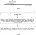
- FIG. 3 is a schematic diagram of a sliding window according to an embodiment of this application.
- a rectangular box in the figure may correspond to a sliding window, and each point on a coordinate axis may correspond to one signal.
- n may correspond to a current signal, for example, correspond to x ( n ).
- N may represent a length of the sliding window, that is, one sliding window corresponds to N signals.
- M may represent a moving distance of the sliding window, that is, a corresponding parameter is calculated at an interval of M signals.
- the sliding window moves twice.
- the sliding window moves from a location corresponding to a signal n-M to a location corresponding to a signal n, and then moves from the location corresponding to the signal n to a location corresponding to a signal n+M.
- three times of calculation may be performed respectively for the foregoing three locations.
- the sliding window algorithm may be used in a related process of step S203 to step S208.
- the related process of step S203 to step S208 may be performed and the related parameter is recalculated based on a total of N signals including a current signal and N-1 signals before the current signal.
- Step S203 A processor filters the reference signal based on the transmission function of the secondary path, to determine a filtered reference signal.
- the reference signal that passes through the secondary path (that is, the filtered reference signal, and reference can be made to x g ( n ) in FIG. 2 ) is first obtained through calculation. Then, the parameter of filtering for determining the audio signal is adjusted based on the reference signal that passes through the secondary path. In this process, impact of the secondary path on the noise reduction effect is considered. In this way, a better noise reduction effect can be implemented.
- a white noise signal may be played by using the speaker, and a signal collected by the second sensor is recorded, to estimate the transmission function of the secondary path.
- a least mean square (least mean square, LMS) algorithm or Wiener filtering may be used to estimate the secondary path, to obtain the transmission function of the secondary path, or another manner may be used.
- the sliding window algorithm may be used to filter the reference signal at an interval of M reference signals based on the transmission function of the secondary path, to determine the filtered reference signal.
- Step S204 The processor determines the primary noise signal based on the residual signal and an audio signal that is obtained after the audio signal is filtered based on the transmission function of the secondary path.
- the primary noise signal d ( n ) at the error point further needs to be obtained through calculation.
- the parameter may be adjusted by using a correlation between the filtered reference signal and the primary noise signal, so that a finally determined audio signal can better cancel the noise signal at the human ear.
- the primary noise signal (refer to d ⁇ (n) in FIG. 2 ) is obtained through calculation and reconstruction based on the collected residual signal and the audio signal and by using the determined transmission function of the secondary path.
- J may represent a maximum value of a length of the filter corresponding to the transmission function ⁇ of the secondary path, and the length of the filter may represent a quantity of signals filtered when the filter performs one filtering (namely, a quantity of sampling points of the input signal processed by the filter once).
- I may represent a maximum value of a length of the Wiener filter W for determining the audio signal, and may indicate a quantity of signals filtered when the Wiener filter performs one filtering.
- the sliding window algorithm may be used to determine the primary noise signal at an interval of M residual signals and M audio signals obtained after the audio signal is filtered based on the transmission function of the secondary path.
- Step S205 The processor determines an autocorrelation matrix based on the filtered reference signal.
- R xx ( n ) may represent an autocorrelation matrix corresponding to x g ( n ), and may indicate an autocorrelation degree of x g ( n ) .
- x g T n may represent a transpose matrix of x g ( n ) .
- first N reference signals on which ⁇ filtering is performed may be obtained by using the sliding window algorithm shown in FIG. 3 , to calculate an autocorrelation matrix corresponding to x g ( n ) .
- N may represent the length of the sliding window.
- Step S206 The processor determines a cross-correlation matrix based on the filtered reference signal and the primary noise signal.
- R xd ( n ) may represent an autocorrelation matrix corresponding to x g ( n ) and d ⁇ ( n ), and may indicate a correlation degree between x g ( n ) and d ⁇ ( n ) .
- d ⁇ T ( n ) may represent a transpose matrix of d ⁇ ( n ).
- d ⁇ ( n ) is calculated by using the sliding window algorithm shown in FIG. 3 .
- the first N signals are obtained to calculate the cross-correlation matrix corresponding to x g ( n ) and d ⁇ ( n ) .
- N may represent the length of the sliding window.
- Step S207 The processor updates, based on the autocorrelation matrix and the cross-correlation matrix, a coefficient of Wiener filtering for determining the audio signal.
- a target direction W wn ( n ) of the Wiener filter coefficient may be determined based on the autocorrelation matrix and the cross-correlation matrix.
- W wn n R xx ⁇ 1 n R xd n R xx ⁇ 1 n may represent an inverse matrix of R xx ( n ) .
- a change direction ⁇ W ( n ) of the filter may be determined based on a difference between the target direction W wn ( n ) of the Wiener filter and a previous Wiener filtering coefficient W( n -1).
- ⁇ W n W wn n ⁇ W n ⁇ 1
- a current coefficient W( n ) corresponding to the W may be determined.
- W n W n ⁇ 1 ⁇ ⁇ ⁇ W n L
- ⁇ may represent a change amplitude of the Wiener filter.
- L may represent the length of the Wiener filter, and a value of L may be consistent with a value of the length N of the sliding window. In this way, a better noise reduction effect may be obtained.
- the processor needs to update the coefficient W ( n ) corresponding to W point by point.
- the sliding window algorithm may be used to update ⁇ W ( n ) at an interval of M points.
- a corresponding W ( n ) of the Wiener filter needs to be updated by using a current ⁇ W ( n ) (regardless of whether the current ⁇ W ( n ) is updated), ⁇ , and L.
- Step S208 The processor determines a noise reduction amount based on the primary noise signal and the residual signal, and adjusts the parameter of the Wiener filter and a parameter of the sliding window based on the determined noise reduction amount.
- the noise reduction amount may be first determined, and the related parameter is adjusted accordingly, to adjust a noise reduction state based on a current noise reduction effect, to obtain a larger noise reduction amount and a quicker noise reduction that responds in a timely manner.
- NR n 10 lg P d n P e n
- P d ( n ) and P e ( n ) may respectively represent power corresponding to d ⁇ ( n ) and e ( n ).
- P d ( n ) and P e ( n ) may respectively represent power corresponding to d ⁇ ( n ) and e ( n ).
- P d n 1 ⁇ ⁇ P d n ⁇ 1 ⁇ ⁇ d ⁇ 2 n
- P e n 1 ⁇ ⁇ P e n ⁇ 1 ⁇ ⁇ e 2 n
- ⁇ may represent a parameter for controlling a sliding speed, and may be preset, and a value of ⁇ is, for example, 0.01.
- the parameter of the Wiener filter and the parameter of the sliding window may be adjusted based on the noise reduction amount obtained through calculation.
- the adjustable parameters may include, for example, the change amplitude ⁇ of the Wiener filter coefficient, the length L of the Wiener filter, the moving distance M of the sliding window, and the length N of the sliding window.
- the noise reduction amount may be inversely proportional to ⁇ and directly proportional to L, M, and N.
- Values of the foregoing parameters may be further determined based on a value of the noise reduction amount NR.
- L r NR ⁇ I
- I may represent the maximum value corresponding to the length of the Wiener filter, and may be preset.
- M may be determined based on the value of L, and values of M and L may be equal.
- r(NR) may represent a proportion coefficient determined based on NR.
- N r NR ⁇ N 0
- a value of N 0 may represent a maximum value corresponding to the length of the sliding window, and may be preset.
- ⁇ 0 may represent a maximum value corresponding to the change amplitude of the coefficient of the Wiener filter, and may be preset.
- r ⁇ ( NR ) may represent a proportion coefficient determined based on NR.
- r NR 1 ⁇ ⁇ 1 1 + exp ⁇ NR ⁇ 2 + ⁇ 3 ] + ⁇ 1
- ⁇ 1 , ⁇ 2 , and ⁇ 3 are preset parameters.
- ⁇ 1 may be used to constrain a lower limit of r(NR), and a value range of ⁇ 1 is, for example, 0.05 to 0.1.
- ⁇ 2 may be used to adjust a slope of a function, and a larger value of ⁇ 2 may indicate that a corresponding parameter is adjusted more quickly with the noise reduction amount.
- ⁇ 3 may be used to determine a value of r(NR) when the noise reduction amount is 0, and indicates a starting noise reduction amount when r(NR) starts to increase.
- ⁇ 4 , ⁇ 5 , and ⁇ 6 are preset parameters.
- ⁇ 1 may be used to constrain a lower limit of r ⁇ ( NR ), and a value range of ⁇ 4 is, for example, 0.05 to 0.1.
- ⁇ 5 may be used to adjust a slope of a function, and a larger value of ⁇ 5 may indicate that a corresponding parameter is adjusted more quickly with the noise reduction amount.
- ⁇ 6 may be used to determine a value of r ⁇ ( NR ) when the noise reduction amount is 0, and indicates a starting noise reduction amount when r ⁇ ( NR ) starts to increase.
- values of ⁇ 1 and ⁇ 4 may be the same or may be different. This is the same for ⁇ 2 and ⁇ 5 , and ⁇ 3 and ⁇ 6 .
- Step S209 The processor performs Wiener filtering on the reference signal based on the determined coefficient of the Wiener filter to determine the audio signal, and emits a sound wave corresponding to the audio signal by using the speaker.
- I may represent the maximum value corresponding to the length L of the Wiener filter, and may be preset.
- the determined corresponding audio signal may cancel the noise signal at the human ear, to achieve an effect of noise reduction.
- FIG. 4 is a flowchart of a signal processing method according to an embodiment of this application. The method may be applied to the foregoing signal processing system. As shown in FIG. 4 , the method includes the following steps:
- real-time parameter adjustment is performed by using the second audio signal collected at the human ear, where the second audio signal is actual noise at the human ear, that is, noise (namely, the foregoing residual signal) remained after the sound wave generated by the speaker cancels the third audio signal.
- the first audio signal is processed by using an adjusted parameter, so that the third audio signal is obtained to indicate the speaker to emit the sound wave to cancel the noise.
- a noise reduction amount is larger, and a noise reduction effect is better. This improves a comfort degree of an occupant.
- the first audio signal may be the foregoing reference signal x(n)
- the second audio signal may be the foregoing residual signal e(n)
- the third audio signal may be the foregoing audio signal y ( n ).
- the second audio signal at the human ear may be a residual signal collected at any location in a preset range near the human ear of the occupant in a vehicle.
- the plurality of first sensors may be disposed in different locations, and the plurality of second sensors may also be disposed in different locations.
- the first processing manner is Wiener filtering. In this way, a larger noise reduction amount can be obtained, and quicker noise reduction can be implemented.
- the first processing manner may alternatively be another processing manner in which the first audio signal may be processed to determine the third audio signal.
- the parameter for processing the first audio signal in the first processing manner may be, for example, the foregoing coefficient of the Wiener filter W.
- step S401 refer to step S201 in FIG. 2 .
- step S402 refer to step S202 in FIG. 2 .
- step S403 refer to related descriptions in step S209 in FIG. 2 .
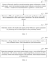
- FIG. 5 is a flowchart of a signal processing method according to an embodiment of this application. As shown in FIG. 5 , the method further includes the following steps:
- the fourth audio signal is determined by estimating the transmission manner of transmission from the speaker to the second sensor, so that a transmission process of the first audio signal is considered.
- the fifth audio signal is obtained through reconstruction, so that initial noise heard by the occupant before noise reduction may be obtained through calculation.
- the parameter is adjusted with reference to the two, so that a corresponding sound wave emitted by the speaker as indicated by an adjusted parameter can better cancel the noise. In this way, a larger noise reduction amount is obtained.
- the parameter may be adjusted in a timely manner through real-time calculation of the parameter based on the two, so that a noise reduction state can be restored more quickly when interference occurs, and robustness is higher. In this way, a better noise reduction effect is obtained.
- the second processing manner may be, for example, the transmission function ⁇ of the foregoing secondary path.
- the fourth audio signal may be a reference signal x g ( n ) obtained after the reference signal is filtered based on the transmission function of the secondary path.
- the fifth audio signal may be the foregoing primary noise signal d ⁇ ( n ) obtained through calculation.
- step S501 refer to step S203 in FIG. 2 .
- step S502 refer to step S204 in FIG. 2 .
- step S503 refer to related descriptions in steps S205 to S207 in FIG. 2 .
- determining, based on the fourth audio signal and the fifth audio signal, the parameter for processing the first audio signal in the first processing manner includes: determining, based on an autocorrelation matrix of the fourth audio signal and a cross-correlation matrix of the fourth audio signal and the fifth audio signal, the parameter for processing the first audio signal in the first processing manner.
- an autocorrelation degree of the fourth audio signal and a cross-correlation degree of the fourth audio signal and the fifth audio signal may be considered in a parameter adjustment process, so that a better noise reduction effect is implemented.
- step S205 For an example of a process of determining the autocorrelation matrix, refer to step S205 in FIG. 2 .
- step S206 For an example of a process of determining the cross-correlation matrix, refer to step S206 in FIG. 2 .
- step S207 For an example of determining, based on the autocorrelation matrix of the fourth audio signal and the cross-correlation matrix of the fourth audio signal and the fifth audio signal, the parameter for processing the first audio signal in the first processing manner, refer to related descriptions in step S207 in FIG. 2 .
- FIG. 6 is a flowchart of a signal processing method according to an embodiment of this application.
- the determining, based on an autocorrelation matrix of the fourth audio signal and a cross-correlation matrix of the fourth audio signal and the fifth audio signal, the parameter for processing the first audio signal according to the first processing manner includes the following steps:
- the parameter at the current moment is determined at each moment, so that a large noise reduction amount is stabilized and quick noise reduction is implemented, noise caused by a sudden change of a filter as a consequence of untimely parameter update can be avoided, and a comfort degree of experience of an occupant is improved.
- the change direction of the parameter may be the foregoing ⁇ W ( n ) .
- the signal length during processing in the first processing manner may be a signal length during each processing, and may be the foregoing length L of the Wiener filter.
- the change amplitude of the parameter may be the foregoing ⁇ , and the parameter at the current moment may be the foregoing current coefficient W ( n ) of the Wiener filter.
- the previous moment may be a moment before the current moment, and the parameter of the previous moment may be the foregoing W ( n - 1).
- step S601 and step S602 refer to step S207 in FIG. 2 .
- processing the first audio signal based on the transmission manner and in the second processing manner to determine a fourth audio signal includes: processing, in the second processing manner at an interval of a predetermined window moving distance, the first audio signal of a predetermined window length, to determine the fourth audio signal.
- Determining the fifth audio signal based on the second audio signal and the audio signal obtained after the third audio signal is processed in the second processing manner includes: determining, at an interval of the predetermined window moving distance, the fifth audio signal based on the second audio signal of the predetermined window length and the audio signal that is obtained after the third audio signal is processed in the second processing manner.
- calculation may be performed by using a predetermined window, so that the fourth audio signal and the fifth audio signal do not need to be determined point by point. This reduces a calculation amount.
- the predetermined window moving distance may be the foregoing moving distance M of the sliding window
- the predetermined window length may be the foregoing length N of the sliding window.
- step S203 For the foregoing process, refer to related examples in step S203 and step S204 in FIG. 2 .
- FIG. 7 is a flowchart of a signal processing method according to an embodiment of this application. As shown in FIG. 7 , the method further includes the following steps:
- the noise reduction amount is calculated, and one or more of the following is adjusted based on the noise reduction amount: the change amplitude of the parameter, the signal length, the predetermined window moving distance, and the predetermined window length, so that different noise reduction environments and states can be adapted to in a noise reduction process. In this way, a better noise reduction effect is achieved and user experience is improved.
- the noise reduction amount may be, for example, the foregoing NR.
- a smaller value of the noise reduction amount indicates that larger power of noise reduction is required and a higher speed of noise reduction is required.
- a smaller value of the noise reduction amount indicates a larger change amplitude corresponding to the parameter, a smaller signal length, a smaller predetermined window moving distance, and a smaller predetermined window length.
- a larger value of the noise reduction amount indicates a smaller change amplitude corresponding to the parameter, a larger signal length, a larger predetermined window moving distance, and a larger predetermined window length.
- step S701 and step S702 refer to related descriptions in step S208.
- FIG. 8 is a diagram of a structure of a signal processing apparatus according to an embodiment of this application. As shown in FIG. 8 , the apparatus includes:
- real-time parameter adjustment is performed by using the second audio signal collected at the human ear.
- a current noise reduction state may be considered, and the parameter is adjusted based on the current noise reduction state.
- the first audio signal is processed by using an adjusted parameter to obtain the third audio signal, to indicate the speaker to emit the sound wave to cancel the noise, so that quicker noise reduction can be implemented, a noise reduction amount is larger, a noise reduction effect is better. This improves a comfort degree of an occupant.
- the first processing manner is Wiener filtering.
- the apparatus further includes: a first determining module, configured to process the first audio signal in a second processing manner to determine a fourth audio signal, where the second processing manner indicates a transmission manner in which the sound wave is transmitted from the speaker to the second sensor; a second determining module, configured to determine a fifth audio signal based on the second audio signal and an audio signal that is obtained after the third audio signal is processed in the second processing manner; and a third determining module, configured to determine, based on the fourth audio signal and the fifth audio signal, the parameter for processing the first audio signal in the first processing manner.
- the fourth audio signal is determined by estimating the transmission manner of transmission from the speaker to the second sensor, so that a transmission process of the first audio signal is considered.
- the fifth audio signal is obtained through reconstruction, so that initial noise heard by the occupant before noise reduction may be obtained through calculation.
- the parameter is adjusted with reference to the two, so that a corresponding sound wave emitted by the speaker as indicated by an adjusted parameter can better cancel the noise. In this way, a larger noise reduction amount is obtained.
- the parameter may be adjusted in a timely manner through real-time calculation of the parameter based on the two, so that a noise reduction state can be restored more quickly when interference occurs, and robustness is higher. In this way, a better noise reduction effect is obtained.
- the third determining module is configured to: determine, based on an autocorrelation matrix of the fourth audio signal and a cross-correlation matrix of the fourth audio signal and the fifth audio signal, the parameter for processing the first audio signal in the first processing manner.
- an autocorrelation degree of the fourth audio signal and a cross-correlation degree of the fourth audio signal and the fifth audio signal may be considered in a parameter adjustment process, so that a better noise reduction effect is implemented.
- the determining, based on an autocorrelation matrix of the fourth audio signal and a cross-correlation matrix of the fourth audio signal and the fifth audio signal, the parameter for processing the first audio signal in the first processing manner includes: determining a change direction of the parameter based on the autocorrelation matrix, the cross-correlation matrix, and a parameter at a previous moment; and determining a parameter at a current moment based on one or more of the following: the parameter at the previous moment, a signal length during processing in the first processing manner, the change direction of the parameter, and a change amplitude of the parameter.
- the parameter at the current moment is determined at each moment, so that a large noise reduction amount is stabilized and quick noise reduction is implemented, noise caused by a sudden change of a filter as a consequence of untimely parameter update can be avoided, and a comfort degree of experience of an occupant is improved.
- the first determining module is configured to: process, in the second processing manner at an interval of a predetermined window moving distance, the first audio signal of a predetermined window length, to determine the fourth audio signal; and the second determining module is configured to: determine, at an interval of the predetermined window moving distance, the fifth audio signal based on the second audio signal of the predetermined window length and the audio signal that is obtained after the third audio signal is processed in the second processing manner.
- calculation may be performed by using a predetermined window, so that the fourth audio signal and the fifth audio signal do not need to be determined point by point. This reduces a calculation amount.
- the apparatus further includes: a fourth determining module, configured to determine a noise reduction amount based on the second audio signal and the fifth audio signal; and an adjustment module, configured to adjust, based on the noise reduction amount, one or more of the following: the change amplitude of the parameter, the signal length during processing in the first processing manner, the predetermined window moving distance, and the predetermined window length.
- the noise reduction amount is calculated, and one or more of the following is adjusted based on the noise reduction amount: the change amplitude of the parameter, the signal length, the predetermined window moving distance, and the predetermined window length, so that different noise reduction environments and states can be adapted to in a noise reduction process. In this way, a better noise reduction effect is achieved and user experience is improved.
- FIG. 9 is a diagram of a structure of a signal processing apparatus according to an embodiment of this application.
- the signal processing apparatus is applicable to the signal processing system shown in FIG. 1 , and performs the signal processing method shown in any one of FIG. 2 to FIG. 7 .
- the signal processing apparatus 900 may include a processor 901 and a transceiver 902.
- the signal processing apparatus 900 may include a memory 903.
- the processor 901 is coupled to the transceiver 902 and the memory 903, for example, may be connected through a communication bus.
- the processor 901 is a control center of the signal processing apparatus 900, and may be one processor, or may be a general term of a plurality of processing elements.
- the processor 901 may be one or more central processing units (central processing units, CPUs) or an application-specific integrated circuit (application-specific integrated circuit, ASIC), or may be configured as one or more integrated circuits implementing embodiments of this application, for example, one or more microprocessors, or one or more field programmable gate arrays (field programmable gate arrays, FPGAs).
- the processor 901 may perform various functions of the signal processing apparatus 900 by running or executing a software program stored in the memory 903 and invoking data stored in the memory 903.
- the processor 901 may include one or more CPUs, for example, a CPU 0 and a CPU 1 that are shown in FIG. 9 .
- the signal processing apparatus 900 may also include a plurality of processors, for example, the processor 901 and processor 904 shown in FIG. 9 .
- Each of the processors may be a single-core processor (single-CPU) or a multi-core processor (multi-CPU).
- the processor herein may be one or more communication devices, circuits, and/or processing cores configured to process data (for example, computer program instructions).
- the transceiver 902 may include a receiver and a transmitter (not separately shown in FIG. 9 ).
- the receiver is configured to implement a receiving function
- the transmitter is configured to implement a sending function.
- the transceiver 902 may be integrated with the processor 901, or may exist independently, and is coupled to the processor 901 through an input/output port (not shown in FIG. 9 ) of the signal processing apparatus 900. This is not limited in this embodiment of this application.
- the memory 903 is configured to store a software program for executing the solutions in this application, and the processor 901 controls execution of the software program.
- the processor 901 controls execution of the software program.
- the memory 903 may be but is not limited to a read-only memory (read-only memory, ROM) or another type of static storage communication device capable of storing static information and instructions, a random access memory (random access memory, RAM) or another type of dynamic storage communication device that can store information and instructions, or may be an electrically erasable programmable read-only memory (electrically erasable programmable read-only memory, EEPROM), a compact disc read-only memory (compact disc read-only memory, CD-ROM) or another optical disc storage, an optical disc storage (including a compressed optical disc, a laser disc, an optical disc, a digital versatile disc, a Blu-ray disc, or the like), a magnetic disk storage medium or another magnetic storage communication device, or any other medium that can be configured to carry or store expected program code in a form of instructions or a data structure and that can be accessed by a computer.
- ROM read-only memory
- RAM random access memory
- EEPROM electrically erasable programmable read-only memory
- the memory 903 may be integrated with the processor 901, or may exist independently, and is coupled to the processor 901 through an input/output port (not shown in FIG. 9 ) of the signal processing apparatus 900. This is not limited in this embodiment of this application.
- the structure of the signal processing apparatus 900 shown in FIG. 9 does not constitute a limitation on implementations of the signal processing apparatus.
- An actual signal processing apparatus may include more or fewer components than those shown in the figure, or some components may be combined, or there may be a different component layout.
- An embodiment of this application provides a signal processing apparatus that includes a processor and a memory.
- the memory is configured to store a program
- the processor is configured to execute the program stored in the memory, to enable the apparatus to perform the foregoing method.
- An embodiment of this application provides a computer-readable storage medium, where the computer-readable storage medium stores program instructions, and when the program instructions are executed by a computer, the computer is enabled to implement the foregoing method.
- An embodiment of this application provides a terminal device, and the terminal device may perform the foregoing method.
- An embodiment of this application provides a computer program product that includes program instructions.
- the program instructions When the program instructions are executed by a computer, the computer is enabled to implement the foregoing method.
- An embodiment of this application provides a vehicle.
- the vehicle includes a processor, and the processor is configured to perform the foregoing method.
- the computer-readable storage medium can be a tangible device that can retain and store instructions for use by an instruction execution device.
- the computer-readable storage medium may be, for example, but is not limited to, an electrical storage device, a magnetic storage device, an optical storage device, an electromagnetic storage device, a semiconductor storage device, or any suitable combination thereof.
- Computer-readable program instructions or code described herein can be downloaded to respective computing/processing devices from a computer-readable storage medium, or downloaded to an external computer or external storage device via a network, such as the Internet, a local area network, a wide area network and/or a wireless network.
- the network may include a copper transmission cable, optical fiber transmission, wireless transmission, a router, a firewall, a switch, a gateway computer and/or an edge server.
- a network adapter card or network interface in each computing/processing device receives the computer-readable program instructions from the network and forwards the computer-readable program instructions for storage in a computer-readable storage medium in each computing/processing device.
- These computer-readable program instructions may be provided to a processor of a general-purpose computer, a dedicated computer, or another programmable data processing apparatus to produce a machine, so that the instructions, when executed by the processor of the computer or the another programmable data processing apparatus, create an apparatus for implementing functions/acts specified in one or more blocks in the flowcharts and/or block diagrams.
- These computer-readable program instructions may alternatively be stored in the computer-readable storage medium. These instructions enable a computer, a programmable data processing apparatus, and/or another device to work in a specific manner. Therefore, the computer-readable medium storing the instructions includes an artifact that includes instructions for implementing the various aspects of the functions/acts specified in the one or more blocks in the flowcharts and/or the block diagrams.
- the computer-readable program instructions may alternatively be loaded onto a computer, another programmable data processing apparatus, or another device so that a series of operation steps is performed on the computer, the another programmable data processing apparatus, or the another device to produce a computer-implemented process. Therefore, the instructions executed on the computer, the another programmable data processing apparatus, or the another device implements the functions/acts specified in the one or more blocks in the flowcharts and/or block diagrams.
- each block in the flowcharts or block diagrams may represent a module, a program segment, or a part of the instructions, and the module, the program segment, or the part of the instructions includes one or more executable instructions for implementing a specified logical function.
- a function marked in the block may also occur in a sequence different from that marked in the accompanying drawings. For example, two consecutive blocks may actually be executed substantially in parallel, and may sometimes be executed in a reverse order, depending on a function involved.
- each block in the block diagram and/or the flowchart, and a combination of blocks in the block diagram and/or the flowchart may be implemented by hardware (for example, a circuit or an ASIC (Application-Specific Integrated Circuit, application-specific integrated circuit)) that performs a corresponding function or action, or may be implemented by a combination of hardware and software, for example, firmware.
- hardware for example, a circuit or an ASIC (Application-Specific Integrated Circuit, application-specific integrated circuit)
- ASIC Application-Specific Integrated Circuit, application-specific integrated circuit
Landscapes
- Physics & Mathematics (AREA)
- Engineering & Computer Science (AREA)
- Acoustics & Sound (AREA)
- Multimedia (AREA)
- Health & Medical Sciences (AREA)
- Audiology, Speech & Language Pathology (AREA)
- General Health & Medical Sciences (AREA)
- Noise Elimination (AREA)
- Circuit For Audible Band Transducer (AREA)
- Soundproofing, Sound Blocking, And Sound Damping (AREA)
Abstract
Description
- This application relates to the signal processing field, and in particular, to a signal processing method and apparatus, a storage medium, and a vehicle.
- Vehicles in a high-speed driving process usually have relatively strong noise. The noise includes road noise generated through interaction between a tire and the ground and between a suspension and a body, wind noise, environmental noise, and the like. This seriously affects a comfort degree of an occupant. Energy of noise perceived by people can be reduced by using a noise reduction method, so that noise interference to people can be reduced. Generally, there are two vehicle noise reduction methods: passive noise reduction and active noise reduction. Passive noise reduction is to reduce vehicle noise in a physical noise reduction manner. Active noise reduction generally uses an active noise cancellation (active noise cancellation, ANC) technology to generate, by using a speaker, an audio signal that suppresses a noise signal. After the noise signal meets and superimposes on the noise suppression signal, the noise signal and the noise suppression signal are neutralized to cancel each other, so that a purpose of noise reduction is achieved.
- In the active noise reduction method, a filter is generally applicable only to noise reduction in a single working condition. Because a body structure of an actual vehicle is complex and a working condition is unstable, a real-time adjustment capability in actual application is relatively poor, quick noise reduction cannot be implemented, and a state in which a noise reduction amount is relatively large cannot be stabilized. Therefore, a noise reduction solution with a stronger real-time adjustment capability and a better noise reduction effect is urgently required.
- In view of this, a signal processing method and apparatus, a storage medium, and a vehicle are provided.
- According to a first aspect, an embodiment of this application provides a signal processing method. The method includes: receiving a first audio signal that is collected by one or more first sensors and that is at a noise source; receiving a second audio signal that is collected by one or more second sensors and that is at a human ear, where the first audio signal and the second audio signal are used to determine a parameter for processing the first audio signal in a first processing manner; and sending a third audio signal determined after the first audio signal is processed in the first processing manner, where the third audio signal indicates a speaker to emit a sound wave, and the sound wave is used to cancel noise at the human ear.
- According to this embodiment of this application, in a process of processing the first audio signal, real-time parameter adjustment is performed by using the second audio signal collected at the human ear. In this way, a current noise reduction state may be considered, and the parameter is adjusted based on the current noise reduction state. In this way, the first audio signal is processed by using an adjusted parameter to obtain the third audio signal, to indicate the speaker to emit the sound wave to cancel the noise, so that quicker noise reduction can be implemented, a noise reduction amount is larger, a noise reduction effect is better. This improves a comfort degree of an occupant.
- According to the first aspect and any possible implementation, the method further includes: processing the first audio signal in a second processing manner to determine a fourth audio signal, where the second processing manner indicates a transmission manner in which the sound wave is transmitted from the speaker to the second sensor; determining a fifth audio signal based on the second audio signal and an audio signal that is obtained after the third audio signal is processed in the second processing manner; and determining, based on the fourth audio signal and the fifth audio signal, the parameter for processing the first audio signal in the first processing manner.
- According to this embodiment of this application, the fourth audio signal is determined by estimating the transmission manner of transmission from the speaker to the second sensor, so that a transmission process of the first audio signal is considered. In addition, the fifth audio signal is obtained through reconstruction, so that initial noise heard by the occupant before noise reduction may be obtained through calculation. The parameter is adjusted with reference to the fourth audio signal and the fifth audio signal, so that a corresponding sound wave emitted by the speaker as indicated by an adjusted parameter can better cancel the noise. In this way, a larger noise reduction amount is obtained. In addition, the parameter may be adjusted in a timely manner through real-time calculation of the parameter based on the two, so that a noise reduction state can be restored more quickly when interference occurs, and robustness is higher. In this way, a better noise reduction effect is obtained.
- According to the first aspect and any possible implementation, the determining, based on the fourth audio signal and the fifth audio signal, the parameter for processing the first audio signal in the first processing manner includes: determining, based on an autocorrelation matrix of the fourth audio signal and a cross-correlation matrix of the fourth audio signal and the fifth audio signal, the parameter for processing the first audio signal in the first processing manner.
- In this way, an autocorrelation degree of the fourth audio signal and a cross-correlation degree of the fourth audio signal and the fifth audio signal may be considered in a parameter adjustment process, so that a better noise reduction effect is implemented.
- According to the first aspect and any possible implementation, the determining, based on an autocorrelation matrix of the fourth audio signal and a cross-correlation matrix of the fourth audio signal and the fifth audio signal, the parameter for processing the first audio signal in the first processing manner includes: determining a change direction of the parameter based on the autocorrelation matrix, the cross-correlation matrix, and a parameter at a previous moment; and determining a parameter at a current moment based on one or more of the following: the parameter at the previous moment, a signal length during processing in the first processing manner, the change direction of the parameter, and a change amplitude of the parameter.
- According to this embodiment of this application, the parameter at the current moment is determined at each moment, so that a large noise reduction amount is stabilized and quick noise reduction is implemented, noise caused by a sudden change of a filter as a consequence of untimely parameter update can be avoided, and a comfort degree of experience of an occupant is improved.
- According to the first aspect and any possible implementation, the processing the first audio signal in a second processing manner to determine a fourth audio signal includes: processing, in the second processing manner at an interval of a predetermined window moving distance, the first audio signal of a predetermined window length, to determine the fourth audio signal; and the determining a fifth audio signal based on the second audio signal and an audio signal that is obtained after the third audio signal is processed in the second processing manner includes: determining, at an interval of the predetermined window moving distance, the fifth audio signal based on the second audio signal of the predetermined window length and the audio signal that is obtained after the third audio signal is processed in the second processing manner.
- According to this embodiment of this application, calculation may be performed by using a predetermined window, so that the fourth audio signal and the fifth audio signal do not need to be determined point by point. This reduces a calculation amount.
- According to the first aspect and any possible implementation, the method further includes: determining a noise reduction amount based on the second audio signal and the fifth audio signal; and adjusting, based on the noise reduction amount, one or more of the following: the change amplitude of the parameter, the signal length during processing in the first processing manner, the predetermined window moving distance, and the predetermined window length.
- According to this embodiment of this application, the noise reduction amount is calculated, and one or more of the following is adjusted based on the noise reduction amount: the change amplitude of the parameter, the signal length, the predetermined window moving distance, and the predetermined window length, so that different noise reduction environments and states can be adapted to in a noise reduction process. In this way, a better noise reduction effect is achieved and user experience is improved.
- According to the first aspect and any possible implementation, in a sixth possible implementation of the signal processing method, the first processing manner is Wiener filtering.
- In this way, a larger noise reduction amount can be obtained, and quicker noise reduction can be implemented.
- According to a second aspect, an embodiment of this application provides a signal processing apparatus. The apparatus includes: a first receiving module, configured to receive a first audio signal that is collected by one or more first sensors and that is at a noise source; a second receiving module, configured to receive a second audio signal that is collected by one or more second sensors and that is at a human ear, where the first audio signal and the second audio signal are used to determine a parameter for processing the first audio signal in a first processing manner; and a sending module, configured to send a third audio signal determined after the first audio signal is processed in the first processing manner, where the third audio signal indicates a speaker to emit a sound wave, and the sound wave is used to cancel noise at the human ear.
- According to the second aspect and any possible implementation, the apparatus further includes: a first determining module, configured to process the first audio signal in a second processing manner to determine a fourth audio signal, where the second processing manner indicates a transmission manner in which the sound wave is transmitted from the speaker to the second sensor; a second determining module, configured to determine a fifth audio signal based on the second audio signal and an audio signal that is obtained after the third audio signal is processed in the second processing manner; and a third determining module, configured to determine, based on the fourth audio signal and the fifth audio signal, the parameter for processing the first audio signal in the first processing manner.
- According to the second aspect and any possible implementation, the third determining module is configured to: determine, based on an autocorrelation matrix of the fourth audio signal and a cross-correlation matrix of the fourth audio signal and the fifth audio signal, the parameter for processing the first audio signal in the first processing manner.
- According to the second aspect and any possible implementation, the determining, based on an autocorrelation matrix of the fourth audio signal and a cross-correlation matrix of the fourth audio signal and the fifth audio signal, the parameter for processing the first audio signal in the first processing manner includes: determining a change direction of the parameter based on the autocorrelation matrix, the cross-correlation matrix, and a parameter at a previous moment; and determining a parameter at a current moment based on one or more of the following: the parameter at the previous moment, a signal length during processing in the first processing manner, the change direction of the parameter, and a change amplitude of the parameter.
- According to the second aspect and any possible implementation, the first determining module is configured to: process, in the second processing manner at an interval of a predetermined window moving distance, the first audio signal of a predetermined window length, to determine the fourth audio signal; and the second determining module is configured to: determine, at an interval of the predetermined window moving distance, the fifth audio signal based on the second audio signal of the predetermined window length and the audio signal that is obtained after the third audio signal is processed in the second processing manner.
- According to the second aspect and any possible implementation, the apparatus further includes: a fourth determining module, configured to determine a noise reduction amount based on the second audio signal and the fifth audio signal; and an adjustment module, configured to adjust, based on the noise reduction amount, one or more of the following: the change amplitude of the parameter, the signal length during processing in the first processing manner, the predetermined window moving distance, and the predetermined window length.
- According to the second aspect and any possible implementation, the first processing manner is Wiener filtering.
- According to a third aspect, an embodiment of this application provides a signal processing apparatus, where the apparatus includes a processor and a memory, the memory is configured to store a program, and the processor is configured to execute the program stored in the memory, to enable the apparatus to implement the signal processing method according to any one of the first aspect or the possible implementations of the first aspect.
- According to a fourth aspect, an embodiment of this application provides a terminal device. The terminal device may perform the signal processing method according to any one of the first aspect or the possible implementations of the first aspect.
- According to a fifth aspect, an embodiment of this application provides a computer-readable storage medium, where the computer-readable storage medium stores program instructions, and when the program instructions are executed by a computer, the computer is enabled to implement the method according to any one of the first aspect or the possible implementations of the first aspect.
- To achieve the foregoing objective, a sixth aspect of this application provides a computer program product that includes program instructions. When the program instructions are executed by a computer, the computer is enabled to implement the signal processing method according to any one of the first aspect or the possible implementations of the first aspect.
- According to a seventh aspect, an embodiment of this application provides a vehicle, where the vehicle includes a processor, and the processor is configured to perform the signal processing method according to any one of the first aspect or the possible implementations of the first aspect.
- These aspects and another aspect of this application are more concise and more comprehensive in descriptions of the following (a plurality of) embodiments.
- The accompanying drawings included in this specification and constituting a part of this specification and this specification jointly show example embodiments, features, and aspects of this application, and are intended to explain the principles of this application.
-
FIG. 1 is a schematic diagram of an application scenario according to an embodiment of this application; -
FIG. 2 is a flowchart of a signal processing method according to an embodiment of this application; -
FIG. 3 is a schematic diagram of a sliding window according to an embodiment of this application; -
FIG. 4 is a flowchart of a signal processing method according to an embodiment of this application; -
FIG. 5 is a flowchart of a signal processing method according to an embodiment of this application; -
FIG. 6 is a flowchart of a signal processing method according to an embodiment of this application; -
FIG. 7 is a flowchart of a signal processing method according to an embodiment of this application; -
FIG. 8 is a diagram of a structure of a signal processing apparatus according to an embodiment of this application; and -
FIG. 9 is a diagram of a structure of a signal processing apparatus according to an embodiment of this application. - The following describes various example embodiments, features, and aspects of this application in detail with reference to the accompanying drawings. Identical reference signs in the accompanying drawings indicate elements that have same or similar functions. Although various aspects of embodiments are illustrated in the accompanying drawing, the accompanying drawings are not necessarily drawn in proportion unless otherwise specified.
- The specific term "example" herein means "used as an example, embodiment or illustration". Any embodiment described as an "example" herein is not necessarily explained as being superior or better than other embodiments.
- In addition, to better describe this application, numerous specific details are given in the following specific implementations. A person skilled in the art should understand that this application can also be implemented without some specific details. In some instances, methods, means, elements, and circuits that are well-known to a person skilled in the art are not described in detail, so that the subject matter of this application is highlighted.
-
FIG. 1 is a schematic diagram of an application scenario according to an embodiment of this application. As shown inFIG. 1 , a signal processing method in this embodiment of this application may be used to reduce noise heard by an occupant in a vehicle. A signal processing system in this embodiment of this application may be disposed in a vehicle, and the signal processing system includes a speaker, a sensor, and a processor. - The speaker may be configured to emit a sound wave corresponding to an audio signal, to cancel noise near a human ear of the occupant, so that noise heard by the occupant in the vehicle is reduced. There may be one or more speakers.
- The sensor may include a first sensor and a second sensor.
- There may be one or more first sensors, and the first sensors may include an accelerometer, an in-vehicle radar (for example, a millimeter-wave radar, a lidar, or an ultrasonic radar), a rainfall sensor, a camera, a vehicle posture sensor (for example, a gyroscope), an inertial measurement unit (inertial measurement unit, IMU), and the like. The first sensor may be disposed near a noise source in the vehicle, and is configured to collect a reference signal. The reference signal may indicate noise near the noise source. For example, the reference signal may include an acceleration signal collected by the accelerometer. Because the acceleration signal is proportional to a vibration amplitude of the vehicle, a noise magnitude near the noise source is determined by using the acceleration signal.
- The second sensor may include a microphone. The second sensor may be disposed near the human ear of the occupant in the vehicle, and is configured to collect a residual signal. The residual signal may indicate residual noise heard by the occupant in the vehicle after the sound wave emitted by the speaker cancels noise near the human ear. In a possible implementation, there may be a plurality of occupants in the vehicle, and a plurality of second sensors may be disposed respectively for the plurality of occupants to collect corresponding residual signals.
- The processor may be built into an in-vehicle infotainment (or an audio system) in the vehicle as an in-vehicle computing unit, for example, a digital signal processing (digital signal processor, DSP) chip. The processor may perform calculation based on a signal collected by the sensor, to determine the audio signal. In a possible implementation, the processor may alternatively be disposed outside a cloud server. The server and the vehicle may communicate in a wireless connection manner, for example, may communicate by using mobile communication technologies such as 2G/3G/4G/5G and in wireless communication manner, for example, Wi-Fi, Bluetooth, frequency modulation (frequency modulation, FM), radio modem, or satellite communication. The server may collect, by using communication between the vehicle and the server, the signal collected by the sensor to perform calculation, and send a calculation result back to the corresponding vehicle.
- In a possible implementation, the signal processing system in this embodiment of this application may further include a preamplifier and a power amplifier. The preamplifier may be configured to amplify the residual signal collected by the second sensor to a specific level range, and the power amplifier may be configured to amplify the audio signal to drive the speaker to emit a corresponding sound wave.
- In a process of active noise reduction in the vehicle, because a body structure of the vehicle is complex, and a working condition of the vehicle is unstable, in an existing method for reducing noise in the vehicle, real-time adjustment cannot be performed based on a current noise reduction effect well. As a result, a noise reduction effect is poor. According to the signal processing method in this embodiment of this application, in a process of processing the reference signal to determine the audio signal to perform active noise reduction, the residual signal is further used to adjust a parameter used during processing, so that real-time adjustment can be performed based on a current noise reduction effect, and the audio signal can be dynamically changed. In this way, a larger noise reduction amount can be obtained by canceling a noise signal at the human ear with the dynamically adjusted audio signal, quick noise reduction may be implemented, and a better noise reduction effect is obtained.
- The following uses
FIG. 2 andFIG. 3 as examples to describe in detail the signal processing method in embodiments of this application based on the foregoing signal processing system. -
FIG. 2 is a flowchart of a signal processing method according to an embodiment of this application. The method may be applied to the foregoing signal processing system. As shown inFIG. 2 , the method may include the following steps. - Step S201: A first sensor collects a reference signal.
- There may be one or more first sensors. For the reference signal collected by the first sensor, refer to x(n) in the figure. n may correspond to a current moment, and represent a sequence number in a signal sequence, that is, a signal collected at the current moment is an n th signal in the signal sequence. The reference signal may be a multi-channel signal, that is, one x(n) may correspond to one group of signals, and one signal in each group of signals corresponds to one channel.
- Step S202: A second sensor collects a residual signal.
- Refer to
FIG. 2 . Σ may mean performing summation on the reference signal and an audio signal at an error point, that is, the audio signal cancels the reference signal at the error point, and a signal remains after cancellation is the residual signal. The error point is a location at which the second sensor is placed, and may be any location near a human ear, for example, any location near a left human ear and/or a right human ear. Correspondingly, one or more second sensors may be disposed. If there are a plurality of occupants, a plurality of corresponding second sensors may be further disposed. d(n) in the figure may represent an actual primary noise signal and correspond to noise that actually reaches the error point. G in the figure may represent an actual secondary path and the secondary path may be a path along which a sound wave is transmitted from a speaker to the error point. - In an actual vehicle, after an audio signal (for example, y(n) in the figure) sent by the speaker reaches the error point through the secondary path G, the audio signal and d(n) cancel each other. After cancellation, a remained signal that may be collected by the second sensor is the residual signal. Refer to e(n) in the figure. e(n) may represent noise actually heard by the occupant after noise reduction. In this application, a current noise reduction effect can be better understood by using e(n) collected by the second sensor at the error point, so that a related parameter is adjusted in a more targeted manner, and a noise reduction effect is improved.
- In this application, after the reference signal and the residual signal are obtained, a reference signal filtered by using a filter corresponding to a transmission function of the secondary path may be determined with reference to the known audio signal, and the primary noise signal is obtained through calculation. A related parameter of a Wiener filter (which may be represented by W) configured to obtain the audio signal is updated by using the two signals. In this way, the output audio signal can be dynamically adjusted.
- In a possible implementation, in a process of updating the related parameter of W, the related parameter may be calculated by using a sliding window algorithm. In other words, for some parameters, calculation may not be performed point by point, to reduce a calculation amount.
-
FIG. 3 is a schematic diagram of a sliding window according to an embodiment of this application. As shown inFIG. 3 , a rectangular box in the figure may correspond to a sliding window, and each point on a coordinate axis may correspond to one signal. n may correspond to a current signal, for example, correspond to x(n). N may represent a length of the sliding window, that is, one sliding window corresponds to N signals. M may represent a moving distance of the sliding window, that is, a corresponding parameter is calculated at an interval of M signals. - In a process shown in
FIG. 3 , the sliding window moves twice. The sliding window moves from a location corresponding to a signal n-M to a location corresponding to a signal n, and then moves from the location corresponding to the signal n to a location corresponding to a signal n+M. In this process, three times of calculation may be performed respectively for the foregoing three locations. - The sliding window algorithm may be used in a related process of step S203 to step S208. Refer to
FIG. 3 . In a process of updating the parameter of W, at an interval of M signals, the related process of step S203 to step S208 may be performed and the related parameter is recalculated based on a total of N signals including a current signal and N-1 signals before the current signal. - Step S203: A processor filters the reference signal based on the transmission function of the secondary path, to determine a filtered reference signal.
- After the reference signal is filtered to obtain the audio signal, the audio signal further needs to pass through the secondary path before reaching the error point. Therefore, in this application, the reference signal that passes through the secondary path (that is, the filtered reference signal, and reference can be made to xg (n) in
FIG. 2 ) is first obtained through calculation. Then, the parameter of filtering for determining the audio signal is adjusted based on the reference signal that passes through the secondary path. In this process, impact of the secondary path on the noise reduction effect is considered. In this way, a better noise reduction effect can be implemented. - For the transmission function of the secondary path, refer to Ĝ in
FIG. 2 . In a possible implementation, a white noise signal may be played by using the speaker, and a signal collected by the second sensor is recorded, to estimate the transmission function of the secondary path. A least mean square (least mean square, LMS) algorithm or Wiener filtering may be used to estimate the secondary path, to obtain the transmission function of the secondary path, or another manner may be used. - In a possible implementation, the sliding window algorithm may be used to filter the reference signal at an interval of M reference signals based on the transmission function of the secondary path, to determine the filtered reference signal.
- Step S204: The processor determines the primary noise signal based on the residual signal and an audio signal that is obtained after the audio signal is filtered based on the transmission function of the secondary path.
- After the filtered reference signal xg (n) is determined, in this application, the primary noise signal d(n) at the error point further needs to be obtained through calculation. In this way, when the parameter of filtering for determining the audio signal is updated, the parameter may be adjusted by using a correlation between the filtered reference signal and the primary noise signal, so that a finally determined audio signal can better cancel the noise signal at the human ear.
- In an actual active noise reduction process, the audio signal already cancels the primary noise signal. Therefore, the primary noise signal cannot be directly collected. To dynamically adjust the related parameter of the Wiener filter for determining the audio signal, in this application, the primary noise signal (refer to d̂(n) in
FIG. 2 ) is obtained through calculation and reconstruction based on the collected residual signal and the audio signal and by using the determined transmission function of the secondary path. - For a manner of determining the primary noise signal, refer to Formula (1):

- J may represent a maximum value of a length of the filter corresponding to the transmission function Ĝ of the secondary path, and the length of the filter may represent a quantity of signals filtered when the filter performs one filtering (namely, a quantity of sampling points of the input signal processed by the filter once). I may represent a maximum value of a length of the Wiener filter W for determining the audio signal, and may indicate a quantity of signals filtered when the Wiener filter performs one filtering.


- In a possible implementation, the sliding window algorithm may be used to determine the primary noise signal at an interval of M residual signals and M audio signals obtained after the audio signal is filtered based on the transmission function of the secondary path.
- Step S205: The processor determines an autocorrelation matrix based on the filtered reference signal.
- For a method for determining the autocorrelation matrix, refer to Formula (2):

- Rxx (n) may represent an autocorrelation matrix corresponding to xg (n), and may indicate an autocorrelation degree of xg (n).

- In a possible implementation, at an interval of M reference signals on which Ĝ filtering is performed, first N reference signals on which Ĝ filtering is performed may be obtained by using the sliding window algorithm shown in
FIG. 3 , to calculate an autocorrelation matrix corresponding to xg (n). - For a method for determining the autocorrelation matrix by using the sliding window algorithm, refer to Formula (3):

- N may represent the length of the sliding window.
- Step S206: The processor determines a cross-correlation matrix based on the filtered reference signal and the primary noise signal.
- For a method for determining the cross-correlation matrix, refer to Formula (4):

- Rxd (n) may represent an autocorrelation matrix corresponding to xg (n) and d̂(n), and may indicate a correlation degree between xg (n) and d̂(n). d̂T (n) may represent a transpose matrix of d̂(n).
- In a possible implementation, at an interval of M reference signals on which Ĝ filtering is performed and at an interval of M points, d̂(n) is calculated by using the sliding window algorithm shown in
FIG. 3 . The first N signals are obtained to calculate the cross-correlation matrix corresponding to xg (n) and d̂(n). - For a method for determining the cross-correlation matrix by using the sliding window algorithm, refer to Formula (5):

- N may represent the length of the sliding window.
- Step S207: The processor updates, based on the autocorrelation matrix and the cross-correlation matrix, a coefficient of Wiener filtering for determining the audio signal.
- A target direction Wwn (n) of the Wiener filter coefficient may be determined based on the autocorrelation matrix and the cross-correlation matrix. For a method for determining Wwn (n), refer to Formula (6):


- Then, a change direction ΔW(n) of the filter may be determined based on a difference between the target direction Wwn (n) of the Wiener filter and a previous Wiener filtering coefficient W(n-1). Refer to Formula (7):

- In this way, a current coefficient W(n) corresponding to the W may be determined. For a method for determining W(n), refer to Formula (8):

- µ may represent a change amplitude of the Wiener filter. L may represent the length of the Wiener filter, and a value of L may be consistent with a value of the length N of the sliding window. In this way, a better noise reduction effect may be obtained.
- It should be noted that, to avoid hopping noise, the processor needs to update the coefficient W(n) corresponding to W point by point. For example, in this application, the sliding window algorithm may be used to update ΔW(n) at an interval of M points. However, to avoid hopping noise, for each reference signal, a corresponding W(n) of the Wiener filter needs to be updated by using a current ΔW(n) (regardless of whether the current ΔW(n) is updated), µ, and L.
- Step S208: The processor determines a noise reduction amount based on the primary noise signal and the residual signal, and adjusts the parameter of the Wiener filter and a parameter of the sliding window based on the determined noise reduction amount.
- In this application, the noise reduction amount may be first determined, and the related parameter is adjusted accordingly, to adjust a noise reduction state based on a current noise reduction effect, to obtain a larger noise reduction amount and a quicker noise reduction that responds in a timely manner.
- For a method for determining the noise reduction amount (Noise Reduction, NR), refer to Formula (9):

- Pd (n) and Pe (n) may respectively represent power corresponding to d̂(n) and e(n). For a method for determining Pd (n) and Pe (n), refer to Formula (10) and Formula (11) respectively:


- α may represent a parameter for controlling a sliding speed, and may be preset, and a value of α is, for example, 0.01.
- In a possible implementation, the parameter of the Wiener filter and the parameter of the sliding window may be adjusted based on the noise reduction amount obtained through calculation. The adjustable parameters may include, for example, the change amplitude µ of the Wiener filter coefficient, the length L of the Wiener filter, the moving distance M of the sliding window, and the length N of the sliding window. The noise reduction amount may be inversely proportional to µ and directly proportional to L, M, and N.
- Values of the foregoing parameters may be further determined based on a value of the noise reduction amount NR. For a method for determining L based on NR, refer to Formula (12):

- I may represent the maximum value corresponding to the length of the Wiener filter, and may be preset. In a possible implementation, M may be determined based on the value of L, and values of M and L may be equal. r(NR) may represent a proportion coefficient determined based on NR.
- For a method for determining N based on NR, refer to Formula (13):

- A value of N 0 may represent a maximum value corresponding to the length of the sliding window, and may be preset.
- For a method for determining µ based on NR, refer to Formula (14):

- µ 0 may represent a maximum value corresponding to the change amplitude of the coefficient of the Wiener filter, and may be preset. rµ (NR) may represent a proportion coefficient determined based on NR.
- For a method for determining r(NR) based on NR, refer to Formula (15):

- β 1, β 2, and β 3 are preset parameters. β 1 may be used to constrain a lower limit of r(NR), and a value range of β 1 is, for example, 0.05 to 0.1. β 2 may be used to adjust a slope of a function, and a larger value of β 2 may indicate that a corresponding parameter is adjusted more quickly with the noise reduction amount. β 3 may be used to determine a value of r(NR) when the noise reduction amount is 0, and indicates a starting noise reduction amount when r(NR) starts to increase.
- For a method for determining rµ (NR) based on NR, refer to Formula (16):

- β 4, β 5, and β 6 are preset parameters. β 1 may be used to constrain a lower limit of rµ (NR), and a value range of β 4 is, for example, 0.05 to 0.1. β 5 may be used to adjust a slope of a function, and a larger value of β 5 may indicate that a corresponding parameter is adjusted more quickly with the noise reduction amount. β 6 may be used to determine a value of rµ (NR) when the noise reduction amount is 0, and indicates a starting noise reduction amount when rµ (NR) starts to increase.
- It should be noted that values of β 1 and β 4 may be the same or may be different. This is the same for β 2 and β5, and β 3 and β 6.
- Step S209: The processor performs Wiener filtering on the reference signal based on the determined coefficient of the Wiener filter to determine the audio signal, and emits a sound wave corresponding to the audio signal by using the speaker.
- For a method for determining the audio signal y(n) by performing Wiener filtering on the reference signal based on the determined coefficient of the Wiener filter, refer to Formula (17):

- I may represent the maximum value corresponding to the length L of the Wiener filter, and may be preset.
- In this way, the determined corresponding audio signal may cancel the noise signal at the human ear, to achieve an effect of noise reduction.
-
FIG. 4 is a flowchart of a signal processing method according to an embodiment of this application. The method may be applied to the foregoing signal processing system. As shown inFIG. 4 , the method includes the following steps: - Step S401: Receive a first audio signal that is collected by one or more first sensors and that is at a noise source.
- Step S402: Receive a second audio signal that is collected by one or more second sensors and that is at a human ear, where the first audio signal and the second audio signal are used to determine a parameter for processing the first audio signal in a first processing manner.
- Step S403: Send a third audio signal determined after the first audio signal is processed in the first processing manner, where the third audio signal indicates a speaker to emit a sound wave, and the sound wave is used to cancel noise at the human ear.
- According to this embodiment of this application, in a process of processing the first audio signal, real-time parameter adjustment is performed by using the second audio signal collected at the human ear, where the second audio signal is actual noise at the human ear, that is, noise (namely, the foregoing residual signal) remained after the sound wave generated by the speaker cancels the third audio signal. In this way, the first audio signal is processed by using an adjusted parameter, so that the third audio signal is obtained to indicate the speaker to emit the sound wave to cancel the noise. In this way, quicker noise reduction can be implemented, a noise reduction amount is larger, and a noise reduction effect is better. This improves a comfort degree of an occupant.
- The first audio signal may be the foregoing reference signal x(n), the second audio signal may be the foregoing residual signal e(n), and the third audio signal may be the foregoing audio signal y(n). The second audio signal at the human ear may be a residual signal collected at any location in a preset range near the human ear of the occupant in a vehicle. The plurality of first sensors may be disposed in different locations, and the plurality of second sensors may also be disposed in different locations.
- In a possible implementation, the first processing manner is Wiener filtering. In this way, a larger noise reduction amount can be obtained, and quicker noise reduction can be implemented. The first processing manner may alternatively be another processing manner in which the first audio signal may be processed to determine the third audio signal.
- The parameter for processing the first audio signal in the first processing manner may be, for example, the foregoing coefficient of the Wiener filter W.
- After the sound wave emitted by the speaker cancels the noise at the human ear, an amount of noise heard by the occupant in the vehicle decreases.
- For an example of step S401, refer to step S201 in
FIG. 2 . For an example of step S402, refer to step S202 inFIG. 2 . For an example of step S403, refer to related descriptions in step S209 inFIG. 2 . -
FIG. 5 is a flowchart of a signal processing method according to an embodiment of this application. As shown inFIG. 5 , the method further includes the following steps: - Step S501: Process the first audio signal in a second processing manner to determine a fourth audio signal, where the second processing manner indicates a transmission manner in which the sound wave is transmitted from the speaker to the second sensor.
- Step S502: Determine a fifth audio signal based on the second audio signal and an audio signal that is obtained after the third audio signal is processed in the second processing manner.
- Step S503: Determine, based on the fourth audio signal and the fifth audio signal, the parameter for processing the first audio signal in the first processing manner.
- According to this embodiment of this application, the fourth audio signal is determined by estimating the transmission manner of transmission from the speaker to the second sensor, so that a transmission process of the first audio signal is considered. In addition, the fifth audio signal is obtained through reconstruction, so that initial noise heard by the occupant before noise reduction may be obtained through calculation. The parameter is adjusted with reference to the two, so that a corresponding sound wave emitted by the speaker as indicated by an adjusted parameter can better cancel the noise. In this way, a larger noise reduction amount is obtained. In addition, the parameter may be adjusted in a timely manner through real-time calculation of the parameter based on the two, so that a noise reduction state can be restored more quickly when interference occurs, and robustness is higher. In this way, a better noise reduction effect is obtained.
- The second processing manner may be, for example, the transmission function Ĝ of the foregoing secondary path. The fourth audio signal may be a reference signal xg (n) obtained after the reference signal is filtered based on the transmission function of the secondary path. The fifth audio signal may be the foregoing primary noise signal d̂(n) obtained through calculation.
- For an example of step S501, refer to step S203 in
FIG. 2 . For an example of step S502, refer to step S204 inFIG. 2 . For an example of step S503, refer to related descriptions in steps S205 to S207 inFIG. 2 . - In a possible implementation, determining, based on the fourth audio signal and the fifth audio signal, the parameter for processing the first audio signal in the first processing manner includes: determining, based on an autocorrelation matrix of the fourth audio signal and a cross-correlation matrix of the fourth audio signal and the fifth audio signal, the parameter for processing the first audio signal in the first processing manner.
- In this way, an autocorrelation degree of the fourth audio signal and a cross-correlation degree of the fourth audio signal and the fifth audio signal may be considered in a parameter adjustment process, so that a better noise reduction effect is implemented.
- For an example of a process of determining the autocorrelation matrix, refer to step S205 in
FIG. 2 . For an example of a process of determining the cross-correlation matrix, refer to step S206 inFIG. 2 . For an example of determining, based on the autocorrelation matrix of the fourth audio signal and the cross-correlation matrix of the fourth audio signal and the fifth audio signal, the parameter for processing the first audio signal in the first processing manner, refer to related descriptions in step S207 inFIG. 2 . -
FIG. 6 is a flowchart of a signal processing method according to an embodiment of this application. As shown inFIG. 6 , the determining, based on an autocorrelation matrix of the fourth audio signal and a cross-correlation matrix of the fourth audio signal and the fifth audio signal, the parameter for processing the first audio signal according to the first processing manner includes the following steps: - Step S601: Determine a change direction of the parameter based on the autocorrelation matrix, the cross-correlation matrix, and a parameter at a previous moment.
- Step S602: Determine a parameter at a current moment based on one or more of the following: the parameter at the previous moment, a signal length during processing in the first processing manner, the change direction of the parameter, and a change amplitude of the parameter.
- According to this embodiment of this application, the parameter at the current moment is determined at each moment, so that a large noise reduction amount is stabilized and quick noise reduction is implemented, noise caused by a sudden change of a filter as a consequence of untimely parameter update can be avoided, and a comfort degree of experience of an occupant is improved.
- The change direction of the parameter may be the foregoing ΔW(n). The signal length during processing in the first processing manner may be a signal length during each processing, and may be the foregoing length L of the Wiener filter. The change amplitude of the parameter may be the foregoing µ, and the parameter at the current moment may be the foregoing current coefficient W(n) of the Wiener filter. The previous moment may be a moment before the current moment, and the parameter of the previous moment may be the foregoing W(n- 1).
- For an example of step S601 and step S602, refer to step S207 in
FIG. 2 . - In a possible implementation, processing the first audio signal based on the transmission manner and in the second processing manner to determine a fourth audio signal includes: processing, in the second processing manner at an interval of a predetermined window moving distance, the first audio signal of a predetermined window length, to determine the fourth audio signal.
- Determining the fifth audio signal based on the second audio signal and the audio signal obtained after the third audio signal is processed in the second processing manner includes: determining, at an interval of the predetermined window moving distance, the fifth audio signal based on the second audio signal of the predetermined window length and the audio signal that is obtained after the third audio signal is processed in the second processing manner.
- According to this embodiment of this application, calculation may be performed by using a predetermined window, so that the fourth audio signal and the fifth audio signal do not need to be determined point by point. This reduces a calculation amount.
- For the window, refer to the sliding window shown in
FIG. 3 . The predetermined window moving distance may be the foregoing moving distance M of the sliding window, and the predetermined window length may be the foregoing length N of the sliding window. - For the foregoing process, refer to related examples in step S203 and step S204 in
FIG. 2 . -
FIG. 7 is a flowchart of a signal processing method according to an embodiment of this application. As shown inFIG. 7 , the method further includes the following steps: - Step S701: Determine a noise reduction amount based on the second audio signal and the fifth audio signal.
- Step S702: Adjust, based on the noise reduction amount, one or more of the following: the change amplitude of the parameter, the signal length during processing in the first processing manner, the predetermined window moving distance, and the predetermined window length.
- According to this embodiment of this application, the noise reduction amount is calculated, and one or more of the following is adjusted based on the noise reduction amount: the change amplitude of the parameter, the signal length, the predetermined window moving distance, and the predetermined window length, so that different noise reduction environments and states can be adapted to in a noise reduction process. In this way, a better noise reduction effect is achieved and user experience is improved.
- The noise reduction amount may be, for example, the foregoing NR. A smaller value of the noise reduction amount indicates that larger power of noise reduction is required and a higher speed of noise reduction is required. After adjustment, a smaller value of the noise reduction amount indicates a larger change amplitude corresponding to the parameter, a smaller signal length, a smaller predetermined window moving distance, and a smaller predetermined window length. A larger value of the noise reduction amount indicates a smaller change amplitude corresponding to the parameter, a larger signal length, a larger predetermined window moving distance, and a larger predetermined window length.
- For examples of step S701 and step S702, refer to related descriptions in step S208.
-
FIG. 8 is a diagram of a structure of a signal processing apparatus according to an embodiment of this application. As shown inFIG. 8 , the apparatus includes: - a
first receiving module 801, configured to receive a first audio signal that is collected by one or more first sensors and that is at a noise source; - a
second receiving module 802, configured to receive a second audio signal that is collected by one or more second sensors and that is at a human ear, where the first audio signal and the second audio signal are used to determine a parameter for processing the first audio signal in a first processing manner; and - a sending
module 803, configured to send a third audio signal determined after the first audio signal is processed in the first processing manner, where the third audio signal indicates a speaker to emit a sound wave, and the sound wave is used to cancel noise at the human ear. - According to this embodiment of this application, in a process of processing the first audio signal, real-time parameter adjustment is performed by using the second audio signal collected at the human ear. In this way, a current noise reduction state may be considered, and the parameter is adjusted based on the current noise reduction state. In this way, the first audio signal is processed by using an adjusted parameter to obtain the third audio signal, to indicate the speaker to emit the sound wave to cancel the noise, so that quicker noise reduction can be implemented, a noise reduction amount is larger, a noise reduction effect is better. This improves a comfort degree of an occupant.
- In a possible implementation, the first processing manner is Wiener filtering.
- In this way, a larger noise reduction amount can be obtained, and quicker noise reduction can be implemented.
- In a possible implementation, the apparatus further includes: a first determining module, configured to process the first audio signal in a second processing manner to determine a fourth audio signal, where the second processing manner indicates a transmission manner in which the sound wave is transmitted from the speaker to the second sensor; a second determining module, configured to determine a fifth audio signal based on the second audio signal and an audio signal that is obtained after the third audio signal is processed in the second processing manner; and a third determining module, configured to determine, based on the fourth audio signal and the fifth audio signal, the parameter for processing the first audio signal in the first processing manner.
- According to this embodiment of this application, the fourth audio signal is determined by estimating the transmission manner of transmission from the speaker to the second sensor, so that a transmission process of the first audio signal is considered. In addition, the fifth audio signal is obtained through reconstruction, so that initial noise heard by the occupant before noise reduction may be obtained through calculation. The parameter is adjusted with reference to the two, so that a corresponding sound wave emitted by the speaker as indicated by an adjusted parameter can better cancel the noise. In this way, a larger noise reduction amount is obtained. In addition, the parameter may be adjusted in a timely manner through real-time calculation of the parameter based on the two, so that a noise reduction state can be restored more quickly when interference occurs, and robustness is higher. In this way, a better noise reduction effect is obtained.
- In a possible implementation, the third determining module is configured to: determine, based on an autocorrelation matrix of the fourth audio signal and a cross-correlation matrix of the fourth audio signal and the fifth audio signal, the parameter for processing the first audio signal in the first processing manner.
- In this way, an autocorrelation degree of the fourth audio signal and a cross-correlation degree of the fourth audio signal and the fifth audio signal may be considered in a parameter adjustment process, so that a better noise reduction effect is implemented.
- In a possible implementation, the determining, based on an autocorrelation matrix of the fourth audio signal and a cross-correlation matrix of the fourth audio signal and the fifth audio signal, the parameter for processing the first audio signal in the first processing manner includes: determining a change direction of the parameter based on the autocorrelation matrix, the cross-correlation matrix, and a parameter at a previous moment; and determining a parameter at a current moment based on one or more of the following: the parameter at the previous moment, a signal length during processing in the first processing manner, the change direction of the parameter, and a change amplitude of the parameter.
- According to this embodiment of this application, the parameter at the current moment is determined at each moment, so that a large noise reduction amount is stabilized and quick noise reduction is implemented, noise caused by a sudden change of a filter as a consequence of untimely parameter update can be avoided, and a comfort degree of experience of an occupant is improved.
- In a possible implementation, the first determining module is configured to: process, in the second processing manner at an interval of a predetermined window moving distance, the first audio signal of a predetermined window length, to determine the fourth audio signal; and the second determining module is configured to: determine, at an interval of the predetermined window moving distance, the fifth audio signal based on the second audio signal of the predetermined window length and the audio signal that is obtained after the third audio signal is processed in the second processing manner.
- According to this embodiment of this application, calculation may be performed by using a predetermined window, so that the fourth audio signal and the fifth audio signal do not need to be determined point by point. This reduces a calculation amount.
- In a possible implementation, the apparatus further includes: a fourth determining module, configured to determine a noise reduction amount based on the second audio signal and the fifth audio signal; and an adjustment module, configured to adjust, based on the noise reduction amount, one or more of the following: the change amplitude of the parameter, the signal length during processing in the first processing manner, the predetermined window moving distance, and the predetermined window length.
- According to this embodiment of this application, the noise reduction amount is calculated, and one or more of the following is adjusted based on the noise reduction amount: the change amplitude of the parameter, the signal length, the predetermined window moving distance, and the predetermined window length, so that different noise reduction environments and states can be adapted to in a noise reduction process. In this way, a better noise reduction effect is achieved and user experience is improved.
-
FIG. 9 is a diagram of a structure of a signal processing apparatus according to an embodiment of this application. The signal processing apparatus is applicable to the signal processing system shown inFIG. 1 , and performs the signal processing method shown in any one ofFIG. 2 to FIG. 7 . - As shown in
FIG. 9 , the signal processing apparatus 900 may include aprocessor 901 and atransceiver 902. Optionally, the signal processing apparatus 900 may include amemory 903. Theprocessor 901 is coupled to thetransceiver 902 and thememory 903, for example, may be connected through a communication bus. - The following specifically describes each component of the signal processing apparatus 900 with reference to
FIG. 9 . - The
processor 901 is a control center of the signal processing apparatus 900, and may be one processor, or may be a general term of a plurality of processing elements. For example, theprocessor 901 may be one or more central processing units (central processing units, CPUs) or an application-specific integrated circuit (application-specific integrated circuit, ASIC), or may be configured as one or more integrated circuits implementing embodiments of this application, for example, one or more microprocessors, or one or more field programmable gate arrays (field programmable gate arrays, FPGAs). - Optionally, the
processor 901 may perform various functions of the signal processing apparatus 900 by running or executing a software program stored in thememory 903 and invoking data stored in thememory 903. - In a specific implementation, in an embodiment, the
processor 901 may include one or more CPUs, for example, aCPU 0 and aCPU 1 that are shown inFIG. 9 . - In a possible implementation, the signal processing apparatus 900 may also include a plurality of processors, for example, the
processor 901 andprocessor 904 shown inFIG. 9 . Each of the processors may be a single-core processor (single-CPU) or a multi-core processor (multi-CPU). The processor herein may be one or more communication devices, circuits, and/or processing cores configured to process data (for example, computer program instructions). - Optionally, the
transceiver 902 may include a receiver and a transmitter (not separately shown inFIG. 9 ). The receiver is configured to implement a receiving function, and the transmitter is configured to implement a sending function. - Optionally, the
transceiver 902 may be integrated with theprocessor 901, or may exist independently, and is coupled to theprocessor 901 through an input/output port (not shown inFIG. 9 ) of the signal processing apparatus 900. This is not limited in this embodiment of this application. - The
memory 903 is configured to store a software program for executing the solutions in this application, and theprocessor 901 controls execution of the software program. For specific implementation, refer to the foregoing method embodiment. Details are not described herein again. - The
memory 903 may be but is not limited to a read-only memory (read-only memory, ROM) or another type of static storage communication device capable of storing static information and instructions, a random access memory (random access memory, RAM) or another type of dynamic storage communication device that can store information and instructions, or may be an electrically erasable programmable read-only memory (electrically erasable programmable read-only memory, EEPROM), a compact disc read-only memory (compact disc read-only memory, CD-ROM) or another optical disc storage, an optical disc storage (including a compressed optical disc, a laser disc, an optical disc, a digital versatile disc, a Blu-ray disc, or the like), a magnetic disk storage medium or another magnetic storage communication device, or any other medium that can be configured to carry or store expected program code in a form of instructions or a data structure and that can be accessed by a computer. It should be noted that thememory 903 may be integrated with theprocessor 901, or may exist independently, and is coupled to theprocessor 901 through an input/output port (not shown inFIG. 9 ) of the signal processing apparatus 900. This is not limited in this embodiment of this application. - It should be noted that the structure of the signal processing apparatus 900 shown in
FIG. 9 does not constitute a limitation on implementations of the signal processing apparatus. An actual signal processing apparatus may include more or fewer components than those shown in the figure, or some components may be combined, or there may be a different component layout. - An embodiment of this application provides a signal processing apparatus that includes a processor and a memory. The memory is configured to store a program, and the processor is configured to execute the program stored in the memory, to enable the apparatus to perform the foregoing method.
- An embodiment of this application provides a computer-readable storage medium, where the computer-readable storage medium stores program instructions, and when the program instructions are executed by a computer, the computer is enabled to implement the foregoing method.
- An embodiment of this application provides a terminal device, and the terminal device may perform the foregoing method.
- An embodiment of this application provides a computer program product that includes program instructions. When the program instructions are executed by a computer, the computer is enabled to implement the foregoing method.
- An embodiment of this application provides a vehicle. The vehicle includes a processor, and the processor is configured to perform the foregoing method.
- The computer-readable storage medium can be a tangible device that can retain and store instructions for use by an instruction execution device. The computer-readable storage medium may be, for example, but is not limited to, an electrical storage device, a magnetic storage device, an optical storage device, an electromagnetic storage device, a semiconductor storage device, or any suitable combination thereof.
- Computer-readable program instructions or code described herein can be downloaded to respective computing/processing devices from a computer-readable storage medium, or downloaded to an external computer or external storage device via a network, such as the Internet, a local area network, a wide area network and/or a wireless network. The network may include a copper transmission cable, optical fiber transmission, wireless transmission, a router, a firewall, a switch, a gateway computer and/or an edge server. A network adapter card or network interface in each computing/processing device receives the computer-readable program instructions from the network and forwards the computer-readable program instructions for storage in a computer-readable storage medium in each computing/processing device.
- The various aspects of this application are described herein with reference to the flowcharts and/or block diagrams of the method, the apparatus (system), and the computer program product according to embodiments of this application. It should be understood that each block of the flowcharts and/or block diagrams and a combination of blocks in the flowcharts and/or block diagrams may be implemented by the computer-readable program instructions.
- These computer-readable program instructions may be provided to a processor of a general-purpose computer, a dedicated computer, or another programmable data processing apparatus to produce a machine, so that the instructions, when executed by the processor of the computer or the another programmable data processing apparatus, create an apparatus for implementing functions/acts specified in one or more blocks in the flowcharts and/or block diagrams. These computer-readable program instructions may alternatively be stored in the computer-readable storage medium. These instructions enable a computer, a programmable data processing apparatus, and/or another device to work in a specific manner. Therefore, the computer-readable medium storing the instructions includes an artifact that includes instructions for implementing the various aspects of the functions/acts specified in the one or more blocks in the flowcharts and/or the block diagrams.
- The computer-readable program instructions may alternatively be loaded onto a computer, another programmable data processing apparatus, or another device so that a series of operation steps is performed on the computer, the another programmable data processing apparatus, or the another device to produce a computer-implemented process. Therefore, the instructions executed on the computer, the another programmable data processing apparatus, or the another device implements the functions/acts specified in the one or more blocks in the flowcharts and/or block diagrams.
- The flowcharts and block diagrams in the accompanying drawings show possible implementations of system architectures, functions, and operations of apparatuses, systems, methods, and computer program products according to a plurality of embodiments of this application. In this regard, each block in the flowcharts or block diagrams may represent a module, a program segment, or a part of the instructions, and the module, the program segment, or the part of the instructions includes one or more executable instructions for implementing a specified logical function. In some alternative implementations, a function marked in the block may also occur in a sequence different from that marked in the accompanying drawings. For example, two consecutive blocks may actually be executed substantially in parallel, and may sometimes be executed in a reverse order, depending on a function involved.
- It should also be noted that each block in the block diagram and/or the flowchart, and a combination of blocks in the block diagram and/or the flowchart may be implemented by hardware (for example, a circuit or an ASIC (Application-Specific Integrated Circuit, application-specific integrated circuit)) that performs a corresponding function or action, or may be implemented by a combination of hardware and software, for example, firmware.
- Although this application is described herein with reference to embodiments, in a process of implementing this application that claims protection, a person skilled in the art may understand and implement another variation of the disclosed embodiments by viewing the accompanying drawings, disclosed content, and the appended claims. In the claims, the word "comprising" (comprising) does not exclude another component or another step, and "a" or "one" does not exclude a case of a plurality of objects. A single processor or another unit may implement several functions enumerated in the claims. Some measures are recited in dependent claims that are different from each other, but this does not mean that these measures cannot be combined to produce a great effect.
- The foregoing has described embodiments of this application. The foregoing descriptions are examples, not exhaustive, and are not limited to the disclosed embodiments. Without departing from the scope of the described embodiments, many modifications and variations are apparent to a person of ordinary skill in the technical field. The selection of terms used herein is intended to best explain the principles of embodiments, practical applications, or improvements to technologies in the market, or to enable another person of ordinary skill in the art to understand embodiments disclosed herein.
Claims (18)
- A signal processing method, wherein the method comprises:receiving a first audio signal that is collected by one or more first sensors and that is at a noise source;receiving a second audio signal that is collected by one or more second sensors and that is at a human ear, wherein the first audio signal and the second audio signal are used to determine a parameter for processing the first audio signal in a first processing manner; andsending a third audio signal determined after the first audio signal is processed in the first processing manner, wherein the third audio signal indicates a speaker to emit a sound wave, and the sound wave is used to cancel noise at the human ear.
- The method according to claim 1, wherein the method further comprises:processing the first audio signal in a second processing manner to determine a fourth audio signal, wherein the second processing manner indicates a transmission manner in which the sound wave is transmitted from the speaker to the second sensor;determining a fifth audio signal based on the second audio signal and an audio signal that is obtained after the third audio signal is processed in the second processing manner; anddetermining, based on the fourth audio signal and the fifth audio signal, the parameter for processing the first audio signal in the first processing manner.
- The method according to claim 2, wherein the determining, based on the fourth audio signal and the fifth audio signal, the parameter for processing the first audio signal in the first processing manner comprises:
determining, based on an autocorrelation matrix of the fourth audio signal and a cross-correlation matrix of the fourth audio signal and the fifth audio signal, the parameter for processing the first audio signal in the first processing manner. - The method according to claim 3, wherein the determining, based on an autocorrelation matrix of the fourth audio signal and a cross-correlation matrix of the fourth audio signal and the fifth audio signal, the parameter for processing the first audio signal in the first processing manner comprises:determining a change direction of the parameter based on the autocorrelation matrix, the cross-correlation matrix, and a parameter at a previous moment; anddetermining a parameter at a current moment based on one or more of the following: the parameter at the previous moment, a signal length during processing in the first processing manner, the change direction of the parameter, and a change amplitude of the parameter.
- The method according to any one of claims 2 to 4, wherein the processing the first audio signal in a second processing manner to determine a fourth audio signal comprises:processing, in the second processing manner at an interval of a predetermined window moving distance, the first audio signal of a predetermined window length, to determine the fourth audio signal; andthe determining a fifth audio signal based on the second audio signal and an audio signal that is obtained after the third audio signal is processed in the second processing manner comprises:
determining, at an interval of the predetermined window moving distance, the fifth audio signal based on the second audio signal of the predetermined window length and the audio signal that is obtained after the third audio signal is processed in the second processing manner. - The method according to claim 5, wherein the method further comprises:determining a noise reduction amount based on the second audio signal and the fifth audio signal; andadjusting, based on the noise reduction amount, one or more of the following: the change amplitude of the parameter, the signal length during processing in the first processing manner, the predetermined window moving distance, and the predetermined window length.
- The method according to any one of claims 1 to 6, wherein the first processing manner is Wiener filtering.
- A signal processing apparatus, wherein the apparatus comprises:a first receiving module, configured to receive a first audio signal that is collected by one or more first sensors and that is at a noise source;a second receiving module, configured to receive a second audio signal that is collected by one or more second sensors and that is at a human ear, wherein the first audio signal and the second audio signal are used to determine a parameter for processing the first audio signal in a first processing manner; anda sending module, configured to send a third audio signal determined after the first audio signal is processed in the first processing manner, wherein the third audio signal indicates a speaker to emit a sound wave, and the sound wave is used to cancel noise at the human ear.
- The apparatus according to claim 8, wherein the apparatus further comprises:a first determining module, configured to process the first audio signal in a second processing manner to determine a fourth audio signal, wherein the second processing manner indicates a transmission manner in which the sound wave is transmitted from the speaker to the second sensor;a second determining module, configured to determine a fifth audio signal based on the second audio signal and an audio signal that is obtained after the third audio signal is processed in the second processing manner; anda third determining module, configured to determine, based on the fourth audio signal and the fifth audio signal, the parameter for processing the first audio signal in the first processing manner.
- The apparatus according to claim 9, wherein the third determining module configured to:
determine, based on an autocorrelation matrix of the fourth audio signal and a cross-correlation matrix of the fourth audio signal and the fifth audio signal, the parameter for processing the first audio signal in the first processing manner. - The apparatus according to claim 10, wherein the determining, based on an autocorrelation matrix of the fourth audio signal and a cross-correlation matrix of the fourth audio signal and the fifth audio signal, the parameter for processing the first audio signal in the first processing manner comprises:determining a change direction of the parameter based on the autocorrelation matrix, the cross-correlation matrix, and a parameter at a previous moment; anddetermining a parameter at a current moment based on one or more of the following: the parameter at the previous moment, a signal length during processing in the first processing manner, the change direction of the parameter, and a change amplitude of the parameter.
- The apparatus according to any one of claims 9 to 11, wherein the first determining module is configured to:process, in the second processing manner at an interval of a predetermined window moving distance, the first audio signal of a predetermined window length, to determine the fourth audio signal; andthe second determining module is configured to:
determine, at an interval of the predetermined window moving distance, the fifth audio signal based on the second audio signal of the predetermined window length and the audio signal that is obtained after the third audio signal is processed in the second processing manner. - The apparatus according to claim 12, wherein the apparatus further comprises:a fourth determining module, configured to determine a noise reduction amount based on the second audio signal and the fifth audio signal; andan adjustment module, configured to adjust, based on the noise reduction amount, one or more of the following: the change amplitude of the parameter, the signal length during processing in the first processing manner, the predetermined window moving distance, and the predetermined window length.
- The apparatus according to any one of claims 8 to 13, wherein the first processing manner is Wiener filtering.
- A signal processing apparatus, comprising a processor and a memory, whereinthe memory is configured to store a program; andthe processor is configured to execute the program stored in the memory, to enable the apparatus to implement the method according to any one of claims 1 to 7.
- A computer-readable storage medium, wherein the computer-readable storage medium stores program instructions, and when the program instructions are executed by a computer, the computer is enabled to implement the method according to any one of claims 1 to 7.
- A computer program product, comprising program instructions, wherein when the program instructions are executed by a computer, the computer is enabled to implement the method according to any one of claims 1 to 7.
- A vehicle, wherein the vehicle comprises a processor, and the processor is configured to perform the method according to any one of claims 1 to 7.
Applications Claiming Priority (1)
| Application Number | Priority Date | Filing Date | Title |
|---|---|---|---|
| PCT/CN2021/125919 WO2023065368A1 (en) | 2021-10-22 | 2021-10-22 | Signal processing method and apparatus, and storage medium and vehicle |
Publications (3)
| Publication Number | Publication Date |
|---|---|
| EP4418261A1 true EP4418261A1 (en) | 2024-08-21 |
| EP4418261A4 EP4418261A4 (en) | 2025-01-15 |
| EP4418261B1 EP4418261B1 (en) | 2026-03-11 |
Family
ID=86057825
Family Applications (1)
| Application Number | Title | Priority Date | Filing Date |
|---|---|---|---|
| EP21961111.8A Active EP4418261B1 (en) | 2021-10-22 | 2021-10-22 | Signal processing method and apparatus, and storage medium and vehicle |
Country Status (3)
| Country | Link |
|---|---|
| EP (1) | EP4418261B1 (en) |
| CN (1) | CN116348357A (en) |
| WO (1) | WO2023065368A1 (en) |
Family Cites Families (9)
| Publication number | Priority date | Publication date | Assignee | Title |
|---|---|---|---|---|
| EP2133866B1 (en) * | 2008-06-13 | 2016-02-17 | Harman Becker Automotive Systems GmbH | Adaptive noise control system |
| CN107424596A (en) * | 2017-06-28 | 2017-12-01 | 邢优胜 | Noise initiative control method and system in a kind of car hold |
| EP3648098A4 (en) * | 2017-06-28 | 2020-07-01 | Sony Corporation | INFORMATION PROCESSING DEVICE, INFORMATION PROCESSING SYSTEM, INFORMATION PROCESSING PROCESS AND PROGRAM |
| CN107791970B (en) * | 2017-10-17 | 2019-06-04 | 长春工业大学 | A method of active noise reduction for automobiles based on heuristic dynamic programming |
| CN108538304B (en) * | 2018-03-09 | 2021-10-01 | 华侨大学 | Active control system for interior noise |
| US11034211B2 (en) * | 2019-10-27 | 2021-06-15 | Silentium Ltd. | Apparatus, system and method of active noise control (ANC) based on heating, ventilation and air conditioning (HVAC) configuration |
| CN111572311A (en) * | 2020-05-12 | 2020-08-25 | 上海蔚来汽车有限公司 | Active Noise Cancellation System for Electric Vehicles and Electric Vehicles |
| CN111833841A (en) * | 2020-06-12 | 2020-10-27 | 清华大学苏州汽车研究院(相城) | An active control system, method and vehicle system for automobile road noise |
| CN112562625B (en) * | 2020-11-30 | 2021-08-17 | 深圳百灵声学有限公司 | Active noise reduction filter design method, noise reduction method, system and electronic equipment |
-
2021
- 2021-10-22 CN CN202180008019.9A patent/CN116348357A/en active Pending
- 2021-10-22 EP EP21961111.8A patent/EP4418261B1/en active Active
- 2021-10-22 WO PCT/CN2021/125919 patent/WO2023065368A1/en not_active Ceased
Also Published As
| Publication number | Publication date |
|---|---|
| CN116348357A (en) | 2023-06-27 |
| EP4418261B1 (en) | 2026-03-11 |
| EP4418261A4 (en) | 2025-01-15 |
| WO2023065368A1 (en) | 2023-04-27 |
Similar Documents
| Publication | Publication Date | Title |
|---|---|---|
| KR101103794B1 (en) | Multi Beam Acoustic System | |
| EP3912366B1 (en) | Method and system for creating a plurality of sound zones within an acoustic cavity | |
| EP0998167B1 (en) | Microphone array system | |
| KR102846551B1 (en) | Proximity compensation system for remote microphone technology | |
| US11356788B2 (en) | Spatialized audio rendering for head worn audio device in a vehicle | |
| US8504117B2 (en) | De-noising method for multi-microphone audio equipment, in particular for a “hands free” telephony system | |
| US20140064514A1 (en) | Target sound enhancement device and car navigation system | |
| Ekpo et al. | Regulated-element frost beamformer for vehicular multimedia sound enhancement and noise reduction applications | |
| EP3240301A1 (en) | Voice processing device | |
| EP3520435B1 (en) | Noise estimation for dynamic sound adjustment | |
| CN103680512B (en) | The horizontal lifting system of speech recognition and its method of vehicle array microphone | |
| US10966027B2 (en) | Audio adjustment system | |
| CN116959400A (en) | Noise active control method, device, equipment and readable storage medium | |
| EP4418261B1 (en) | Signal processing method and apparatus, and storage medium and vehicle | |
| US20190103087A1 (en) | System for spectral shaping of vehicle noise cancellation | |
| CN110166023B (en) | Road surface characterization based on filter coefficients | |
| EP3929920A1 (en) | Method and device for processing audio signal, and storage medium | |
| CN119018144B (en) | A vehicle-wide collision avoidance method, device, automobile, and storage medium | |
| WO2018158288A1 (en) | System and method for noise cancellation | |
| EP1261961B1 (en) | Methods and systems for noise reduction for spatially displaced signal sources | |
| US11741926B2 (en) | Echo cancelation | |
| CN112133299A (en) | Sound signal processing method, device and equipment | |
| JP3328946B2 (en) | Active uncomfortable wave control device | |
| JP5383008B2 (en) | Speech intelligibility improvement system and speech intelligibility improvement method | |
| KR20230097549A (en) | Device and Method for Active Noise Cancelling of Vehicle |
Legal Events
| Date | Code | Title | Description |
|---|---|---|---|
| STAA | Information on the status of an ep patent application or granted ep patent |
Free format text: STATUS: THE INTERNATIONAL PUBLICATION HAS BEEN MADE |
|
| PUAI | Public reference made under article 153(3) epc to a published international application that has entered the european phase |
Free format text: ORIGINAL CODE: 0009012 |
|
| STAA | Information on the status of an ep patent application or granted ep patent |
Free format text: STATUS: REQUEST FOR EXAMINATION WAS MADE |
|
| 17P | Request for examination filed |
Effective date: 20240513 |
|
| AK | Designated contracting states |
Kind code of ref document: A1 Designated state(s): AL AT BE BG CH CY CZ DE DK EE ES FI FR GB GR HR HU IE IS IT LI LT LU LV MC MK MT NL NO PL PT RO RS SE SI SK SM TR |
|
| RAP1 | Party data changed (applicant data changed or rights of an application transferred) |
Owner name: SHENZHEN YINWANG INTELLIGENTTECHNOLOGIES CO., LTD. |
|
| A4 | Supplementary search report drawn up and despatched |
Effective date: 20241213 |
|
| RIC1 | Information provided on ipc code assigned before grant |
Ipc: G10K 11/178 20060101ALI20241210BHEP Ipc: B61C 17/04 20060101ALI20241210BHEP Ipc: G10K 11/175 20060101AFI20241210BHEP |
|
| DAV | Request for validation of the european patent (deleted) | ||
| DAX | Request for extension of the european patent (deleted) | ||
| GRAP | Despatch of communication of intention to grant a patent |
Free format text: ORIGINAL CODE: EPIDOSNIGR1 |
|
| STAA | Information on the status of an ep patent application or granted ep patent |
Free format text: STATUS: GRANT OF PATENT IS INTENDED |
|
| INTG | Intention to grant announced |
Effective date: 20250930 |
|
| GRAS | Grant fee paid |
Free format text: ORIGINAL CODE: EPIDOSNIGR3 |
|
| GRAA | (expected) grant |
Free format text: ORIGINAL CODE: 0009210 |
|
| STAA | Information on the status of an ep patent application or granted ep patent |
Free format text: STATUS: THE PATENT HAS BEEN GRANTED |
|
| AK | Designated contracting states |
Kind code of ref document: B1 Designated state(s): AL AT BE BG CH CY CZ DE DK EE ES FI FR GB GR HR HU IE IS IT LI LT LU LV MC MK MT NL NO PL PT RO RS SE SI SK SM TR |
|
| P01 | Opt-out of the competence of the unified patent court (upc) registered |
Free format text: CASE NUMBER: UPC_APP_0003539_4418261/2026 Effective date: 20260202 |
|
| REG | Reference to a national code |
Ref country code: CH Ref legal event code: F10 Free format text: ST27 STATUS EVENT CODE: U-0-0-F10-F00 (AS PROVIDED BY THE NATIONAL OFFICE) Effective date: 20260311 Ref country code: GB Ref legal event code: FG4D |
|
| REG | Reference to a national code |
Ref country code: DE Ref legal event code: R096 Ref document number: 602021049987 Country of ref document: DE |
|
| REG | Reference to a national code |
Ref country code: IE Ref legal event code: FG4D |
|
| REG | Reference to a national code |
Ref country code: CH Ref legal event code: W10 Free format text: ST27 STATUS EVENT CODE: U-0-0-W10-W00 (AS PROVIDED BY THE NATIONAL OFFICE) Effective date: 20260507 |