EP3912366B1 - Method and system for creating a plurality of sound zones within an acoustic cavity - Google Patents
Method and system for creating a plurality of sound zones within an acoustic cavity Download PDFInfo
- Publication number
- EP3912366B1 EP3912366B1 EP20700798.0A EP20700798A EP3912366B1 EP 3912366 B1 EP3912366 B1 EP 3912366B1 EP 20700798 A EP20700798 A EP 20700798A EP 3912366 B1 EP3912366 B1 EP 3912366B1
- Authority
- EP
- European Patent Office
- Prior art keywords
- sound
- signal
- coefficients
- actuator
- exclusion
- Prior art date
- Legal status (The legal status is an assumption and is not a legal conclusion. Google has not performed a legal analysis and makes no representation as to the accuracy of the status listed.)
- Active
Links
- 238000000034 method Methods 0.000 title claims description 80
- 230000007717 exclusion Effects 0.000 claims description 62
- 230000003044 adaptive effect Effects 0.000 claims description 39
- 230000003068 static effect Effects 0.000 claims description 23
- 238000005457 optimization Methods 0.000 claims description 20
- 230000006870 function Effects 0.000 claims description 19
- 230000004044 response Effects 0.000 claims description 19
- 238000004088 simulation Methods 0.000 claims description 17
- 230000005540 biological transmission Effects 0.000 claims description 16
- 238000012546 transfer Methods 0.000 claims description 16
- 230000005236 sound signal Effects 0.000 claims description 5
- 239000011159 matrix material Substances 0.000 description 18
- 238000010586 diagram Methods 0.000 description 8
- 238000002955 isolation Methods 0.000 description 6
- 238000011161 development Methods 0.000 description 3
- 230000018109 developmental process Effects 0.000 description 3
- 230000002452 interceptive effect Effects 0.000 description 3
- 238000013459 approach Methods 0.000 description 2
- 238000002474 experimental method Methods 0.000 description 2
- 230000000295 complement effect Effects 0.000 description 1
- 230000001419 dependent effect Effects 0.000 description 1
- 238000013461 design Methods 0.000 description 1
- 210000005069 ears Anatomy 0.000 description 1
- 230000000694 effects Effects 0.000 description 1
- 238000001914 filtration Methods 0.000 description 1
- 238000009472 formulation Methods 0.000 description 1
- 239000000203 mixture Substances 0.000 description 1
- 238000012545 processing Methods 0.000 description 1
- 230000001755 vocal effect Effects 0.000 description 1
Images


Classifications
-
- G—PHYSICS
- G10—MUSICAL INSTRUMENTS; ACOUSTICS
- G10K—SOUND-PRODUCING DEVICES; METHODS OR DEVICES FOR PROTECTING AGAINST, OR FOR DAMPING, NOISE OR OTHER ACOUSTIC WAVES IN GENERAL; ACOUSTICS NOT OTHERWISE PROVIDED FOR
- G10K11/00—Methods or devices for transmitting, conducting or directing sound in general; Methods or devices for protecting against, or for damping, noise or other acoustic waves in general
- G10K11/16—Methods or devices for protecting against, or for damping, noise or other acoustic waves in general
- G10K11/175—Methods or devices for protecting against, or for damping, noise or other acoustic waves in general using interference effects; Masking sound
- G10K11/178—Methods or devices for protecting against, or for damping, noise or other acoustic waves in general using interference effects; Masking sound by electro-acoustically regenerating the original acoustic waves in anti-phase
- G10K11/1785—Methods, e.g. algorithms; Devices
- G10K11/17853—Methods, e.g. algorithms; Devices of the filter
- G10K11/17854—Methods, e.g. algorithms; Devices of the filter the filter being an adaptive filter
-
- H—ELECTRICITY
- H04—ELECTRIC COMMUNICATION TECHNIQUE
- H04S—STEREOPHONIC SYSTEMS
- H04S7/00—Indicating arrangements; Control arrangements, e.g. balance control
- H04S7/30—Control circuits for electronic adaptation of the sound field
- H04S7/302—Electronic adaptation of stereophonic sound system to listener position or orientation
-
- G—PHYSICS
- G10—MUSICAL INSTRUMENTS; ACOUSTICS
- G10K—SOUND-PRODUCING DEVICES; METHODS OR DEVICES FOR PROTECTING AGAINST, OR FOR DAMPING, NOISE OR OTHER ACOUSTIC WAVES IN GENERAL; ACOUSTICS NOT OTHERWISE PROVIDED FOR
- G10K11/00—Methods or devices for transmitting, conducting or directing sound in general; Methods or devices for protecting against, or for damping, noise or other acoustic waves in general
- G10K11/16—Methods or devices for protecting against, or for damping, noise or other acoustic waves in general
- G10K11/175—Methods or devices for protecting against, or for damping, noise or other acoustic waves in general using interference effects; Masking sound
- G10K11/178—Methods or devices for protecting against, or for damping, noise or other acoustic waves in general using interference effects; Masking sound by electro-acoustically regenerating the original acoustic waves in anti-phase
- G10K11/1785—Methods, e.g. algorithms; Devices
- G10K11/17857—Geometric disposition, e.g. placement of microphones
-
- G—PHYSICS
- G10—MUSICAL INSTRUMENTS; ACOUSTICS
- G10K—SOUND-PRODUCING DEVICES; METHODS OR DEVICES FOR PROTECTING AGAINST, OR FOR DAMPING, NOISE OR OTHER ACOUSTIC WAVES IN GENERAL; ACOUSTICS NOT OTHERWISE PROVIDED FOR
- G10K11/00—Methods or devices for transmitting, conducting or directing sound in general; Methods or devices for protecting against, or for damping, noise or other acoustic waves in general
- G10K11/16—Methods or devices for protecting against, or for damping, noise or other acoustic waves in general
- G10K11/175—Methods or devices for protecting against, or for damping, noise or other acoustic waves in general using interference effects; Masking sound
- G10K11/178—Methods or devices for protecting against, or for damping, noise or other acoustic waves in general using interference effects; Masking sound by electro-acoustically regenerating the original acoustic waves in anti-phase
- G10K11/1787—General system configurations
- G10K11/17879—General system configurations using both a reference signal and an error signal
- G10K11/17881—General system configurations using both a reference signal and an error signal the reference signal being an acoustic signal, e.g. recorded with a microphone
-
- G—PHYSICS
- G10—MUSICAL INSTRUMENTS; ACOUSTICS
- G10K—SOUND-PRODUCING DEVICES; METHODS OR DEVICES FOR PROTECTING AGAINST, OR FOR DAMPING, NOISE OR OTHER ACOUSTIC WAVES IN GENERAL; ACOUSTICS NOT OTHERWISE PROVIDED FOR
- G10K11/00—Methods or devices for transmitting, conducting or directing sound in general; Methods or devices for protecting against, or for damping, noise or other acoustic waves in general
- G10K11/16—Methods or devices for protecting against, or for damping, noise or other acoustic waves in general
- G10K11/175—Methods or devices for protecting against, or for damping, noise or other acoustic waves in general using interference effects; Masking sound
- G10K11/178—Methods or devices for protecting against, or for damping, noise or other acoustic waves in general using interference effects; Masking sound by electro-acoustically regenerating the original acoustic waves in anti-phase
- G10K11/1787—General system configurations
- G10K11/17879—General system configurations using both a reference signal and an error signal
- G10K11/17883—General system configurations using both a reference signal and an error signal the reference signal being derived from a machine operating condition, e.g. engine RPM or vehicle speed
-
- G—PHYSICS
- G10—MUSICAL INSTRUMENTS; ACOUSTICS
- G10K—SOUND-PRODUCING DEVICES; METHODS OR DEVICES FOR PROTECTING AGAINST, OR FOR DAMPING, NOISE OR OTHER ACOUSTIC WAVES IN GENERAL; ACOUSTICS NOT OTHERWISE PROVIDED FOR
- G10K11/00—Methods or devices for transmitting, conducting or directing sound in general; Methods or devices for protecting against, or for damping, noise or other acoustic waves in general
- G10K11/16—Methods or devices for protecting against, or for damping, noise or other acoustic waves in general
- G10K11/175—Methods or devices for protecting against, or for damping, noise or other acoustic waves in general using interference effects; Masking sound
- G10K11/178—Methods or devices for protecting against, or for damping, noise or other acoustic waves in general using interference effects; Masking sound by electro-acoustically regenerating the original acoustic waves in anti-phase
- G10K11/1787—General system configurations
- G10K11/17885—General system configurations additionally using a desired external signal, e.g. pass-through audio such as music or speech
-
- H—ELECTRICITY
- H04—ELECTRIC COMMUNICATION TECHNIQUE
- H04S—STEREOPHONIC SYSTEMS
- H04S7/00—Indicating arrangements; Control arrangements, e.g. balance control
- H04S7/30—Control circuits for electronic adaptation of the sound field
- H04S7/301—Automatic calibration of stereophonic sound system, e.g. with test microphone
-
- G—PHYSICS
- G10—MUSICAL INSTRUMENTS; ACOUSTICS
- G10K—SOUND-PRODUCING DEVICES; METHODS OR DEVICES FOR PROTECTING AGAINST, OR FOR DAMPING, NOISE OR OTHER ACOUSTIC WAVES IN GENERAL; ACOUSTICS NOT OTHERWISE PROVIDED FOR
- G10K2210/00—Details of active noise control [ANC] covered by G10K11/178 but not provided for in any of its subgroups
- G10K2210/10—Applications
- G10K2210/128—Vehicles
- G10K2210/1282—Automobiles
-
- G—PHYSICS
- G10—MUSICAL INSTRUMENTS; ACOUSTICS
- G10K—SOUND-PRODUCING DEVICES; METHODS OR DEVICES FOR PROTECTING AGAINST, OR FOR DAMPING, NOISE OR OTHER ACOUSTIC WAVES IN GENERAL; ACOUSTICS NOT OTHERWISE PROVIDED FOR
- G10K2210/00—Details of active noise control [ANC] covered by G10K11/178 but not provided for in any of its subgroups
- G10K2210/30—Means
- G10K2210/301—Computational
- G10K2210/3019—Cross-terms between multiple in's and out's
-
- G—PHYSICS
- G10—MUSICAL INSTRUMENTS; ACOUSTICS
- G10K—SOUND-PRODUCING DEVICES; METHODS OR DEVICES FOR PROTECTING AGAINST, OR FOR DAMPING, NOISE OR OTHER ACOUSTIC WAVES IN GENERAL; ACOUSTICS NOT OTHERWISE PROVIDED FOR
- G10K2210/00—Details of active noise control [ANC] covered by G10K11/178 but not provided for in any of its subgroups
- G10K2210/30—Means
- G10K2210/301—Computational
- G10K2210/3046—Multiple acoustic inputs, multiple acoustic outputs
-
- H—ELECTRICITY
- H04—ELECTRIC COMMUNICATION TECHNIQUE
- H04R—LOUDSPEAKERS, MICROPHONES, GRAMOPHONE PICK-UPS OR LIKE ACOUSTIC ELECTROMECHANICAL TRANSDUCERS; DEAF-AID SETS; PUBLIC ADDRESS SYSTEMS
- H04R2499/00—Aspects covered by H04R or H04S not otherwise provided for in their subgroups
- H04R2499/10—General applications
- H04R2499/13—Acoustic transducers and sound field adaptation in vehicles
-
- H—ELECTRICITY
- H04—ELECTRIC COMMUNICATION TECHNIQUE
- H04R—LOUDSPEAKERS, MICROPHONES, GRAMOPHONE PICK-UPS OR LIKE ACOUSTIC ELECTROMECHANICAL TRANSDUCERS; DEAF-AID SETS; PUBLIC ADDRESS SYSTEMS
- H04R3/00—Circuits for transducers, loudspeakers or microphones
- H04R3/12—Circuits for transducers, loudspeakers or microphones for distributing signals to two or more loudspeakers
Definitions
- the present document relates to a method and system for creating a plurality of sound zones within an acoustic cavity.
- it relates to a method and system for creating a plurality of individual sound zones within a vehicle cockpit.
- the vehicle cockpit is filled by chaotically mixed sounds, e.g., targeted vocal messages, hands-free calls, broadcastings from a vehicle audio system, individual screen programs, video games, voice messages of a navigation system, etc.
- chaotically mixed sounds e.g., targeted vocal messages, hands-free calls, broadcastings from a vehicle audio system, individual screen programs, video games, voice messages of a navigation system, etc.
- One method is to create a sound isolation between the different sound zones. For example, it is known that headrest speakers or directional speakers can be used to generate and control a localized sound in one sound zone. Cross-talk cancellation means can be added in another sound zone to reduce the unwanted noise which leaks from the one sound zone.
- US 2017/034623 A1 relates to a system and method for generating a sound wave field around a listening position and discloses a method for creating a plurality of sound zones within an acoustic cavity using a plurality of actuators and associated adaptive filters.
- a plurality of error sensors are provided for generating a plurality of error signals.
- the method further comprises the provision of an audio data signal for generating a desired sound in a desired sound zone of the plurality of sound zones.
- a set of actuator generation coefficients, a set of actuator exclusion coefficients, and a set of sensor weighting coefficients are provided. For each actuator a respective drive signal is provided based on an input signal.
- a respective generation input signal is generated based on the provided audio data signal, generating a respective weighted error signal based on the set of sensor weighting coefficients and the respective error signal, generating a reference signal based on the provided audio data signal and a secondary sound path model representing a plurality of acoustic transmission paths from each of the plurality of actuators to each of the plurality of error sensor.
- the updated filter coefficients are then generated based on the respective weighted error signal and the reference signal to reduce the respective weighted error signal.
- US 2019/014430A1 relates to a loudspeaker-room system.
- CHUNG HANWOOK ET AL "Adaptive Crosstalk Cancellation Using Common Acoustical Pole and Zero (CAPZ) Model-Common Pole Estimation", AES CONVENTION 131; 19 October 2011 (2011-10-19 ), relates to adaptive crosstalk cancellation.
- BETLEHEM TERENCE ET AL "Personal Sound Zones: Delivering interface-free audio to multiple listeners", IEEE SIGNAL PROCESSING MAGAZINE, IEEE SERVICE CENTER, PISCATAWAY, NJ, US, vol. 32, no.
- each of the adaptive filters receives the provided audio data signal x ( n ) as the input signal, and generates a respective output signal y ( n ) based on the input signal and the at least one filter coefficient.
- the method further comprises providing, for each of the plurality of actuators, the respective drive signal for generating the respective acoustic output, comprising: generating a respective generation input signal, based on the set of actuator generation coefficients kg k and the provided audio data signal x ( n ); generating a respective exclusion input signal, based on the set of actuator exclusion coefficients ke k and the respective output signal y ( n ); generating the respective drive signal based on the respective generation input signal and the respective exclusion input signal.
- the method further comprises: generating, for each of the adaptive filters, at least one respective updated filter coefficient, comprising: generating a respective weighted error signal, based on the set of sensor weighting coefficients me m and the respective error signal e ; generating a reference signal x' ( n ) based on the provided audio data signal x ( n ), the set of actuator exclusion coefficients ke k , and a secondary sound path model ⁇ representing a plurality of acoustic transmission paths from each of the plurality of actuators to each of the plurality of error sensor; generating the respective updated filter coefficient based on the respective weighted error signal and the reference signal x' ( n ), to reduce the respective weighted error signal.
- a sound zone may be a volume within the acoustic cavity, typically around a head or ears of a person.
- the sound zone may be a volume corresponds to an individual seat position, e.g., a front seat position, a rear seat position.
- An acoustic cavity may be a substantially closed volume, within which acoustic sounds can be transmitted and reflected, e.g., a cockpit of an automotive, a truck, a train or an airplane.
- the provided audio data signal may be a signal representing a noise, e.g., a noise from an engine of a vehicle or a road noise.
- Each adaptive filter may have one filter coefficient.
- each adaptive filter may have more than one filter coefficient.
- more than one filter coefficient is provided for each adaptive filter.
- a medium frequency typically from about 300 to 2000 Hz
- a high frequency typically from about 2000 to 20000 Hz
- part of a sound typically from about 20 to 300 Hz
- the headrest speakers and directional speakers are not designed to work in the low frequency range.
- a low frequency sound has a larger wavelength in relation to a size of an acoustic cavity, e.g., a vehicle cockpit, comparing with the medium and high frequency sounds. Due to the larger wavelength, the low frequency sounds are coupled to acoustic resonances of the acoustic cavity and therefore are difficult to handle locally within a part of the acoustic cavity.
- the known individual sound zones in the acoustic cavity are merely narrowband sound zones, which comprises only the medium and high frequency sounds.
- the low frequency sounds are globally existing within the cavity. That is, the known individual sound zones don't have an individual low frequency sound.
- the inventive concept is to create a plurality of sound zones within an acoustic cavity, such as a vehicle cockpit, wherein each sound zone is provided with an individual desired sound, including a low frequency sound.
- the inventive concept comprises: 1) generating a low frequency (around 20 to 300 Hz) sound, or a low frequency part of a sound, for both a sound zone which needs the generated sound, e.g., a bright sound zone, and a sound zone which does not need it, e.g., a dark sound zone; and 2) cancelling or at least reducing the generated sound in the sound zone which does not need it.
- the inventive concept can be implemented by a plurality of distributed actuators and error sensors, a respective adaptive filter provided for each actuator. Coefficients may be used to control the contribution of each actuator and each sensor in generation and cancellation of a sound for each sound zone.
- the low frequency sound, or the low frequency part of the sound can be individually created for at least two different sound zones within the acoustic cavity, by a global approach.
- the actuators and error sensors do not need to be placed within or in a proximity of the sound zones.
- the arrangement of the actuators and/or error sensors can be more flexible.
- each sound zone within the acoustic cavity may be provided with an individual low frequency sound or an individual low frequency part of a sound. A feeling of immersiveness for the person within the sound zone will be enhanced, especially for music experiences.
- the individual sound zones are created by a global approach instead of performing localised sound generation/cancellation for each sound zone, the sound leakages between different sound zones can be handled more efficiently such that a better sound isolation between different sound zones can be achieved.
- the invention can be implemented in a vehicle cockpit, or any other acoustic cavity, wherein the notion of low frequencies is relative to the characteristic size of the acoustic cavity, such as a cockpit of an automobile, a truck, a train or an airplane.
- the error sensor may be a microphone.
- the actuator may be a loudspeaker or a vibrating panel.
- ANC Active noise control
- a typical ANC system in a vehicle comprises a controller, e.g., a digital signal processor (DSP), and a distributed system of actuators and sensors, whose positions and characteristics are selected for optimally performing in a low frequency range, typically from 20 to 300 Hz.
- the actuators may be loudspeakers or vibrating panels.
- the sensors may be microphones.
- the unwanted sound can be described as a pressure wave having an amplitude and a phase.
- the ANC system can emit a wave with an equal amplitude, but a phase of 180°, i.e. an inverted phase, or anti-phase, of the unwanted wave, to cancel the unwanted wave.
- the system for creating a plurality of sound zones can work in parallel with any existing ANC system dedicated for controlling, e.g., an engine noise and/or a road noise, without interfering with the ANC system.
- the method/system can also be used for active noise control.
- the method/system can also be used for active noise control of an engine noise or a road noise.
- At least one set of the set of actuator generation coefficients kg k , the set of actuator exclusion coefficients ke k , and the set of sensor weighting coefficients me m may be determined by an optimization process.
- the optimization process may comprise: determining a plurality of monitor locations within the acoustic cavity; determining, for each of a plurality of acoustic transmission paths from each of the plurality of actuators to each of the plurality of monitor locations, a respective transfer function; wherein at least one monitor location may be arranged within each of the plurality of sound zones.
- the transfer function may be a mathematical relation between a sound source and a response, e.g., from an actuator to a monitor location, or an error sensor.
- An acoustic transmission path therebetween can be fully characterised based the transfer function.
- the optimization process may further comprise: providing a monitor sensor at each of the plurality of monitor locations, and determining the respective transfer function by measuring a response at the provided monitor sensor.
- the monitor sensor may be a microphone.
- Said determining the respective transfer function by measuring may comprise: driving at least one of the plurality of actuators with a signal, preferably a white or pink noise signal, and measuring a response by the provided monitor sensor.
- the optimization process may comprise: determining the respective transfer function by simulation.
- the optimization process may comprise: determining the set of actuator generation coefficients kg k for generating a first sound at a first monitor location arranged within the desired sound zone, wherein a first value representing the first sound may be greater than a first threshold.
- the first value may be a squared pressure level of the first sound, expressed as ⁇ d monitors 2 ⁇ ⁇ b .
- the first threshold may be a value representing a minimal sound desired to be detected at a monitor location within the desire sound zone.
- the set of actuator generation coefficients kg k may be determined to maximise the first value. That is, to make the first value as great as possible.
- the optimization process may comprise: determining the set of actuator generation coefficients kg k for generating a second sound at a second monitor location arranged outside the desired sound zone, wherein a second value representing the second sound may be smaller than a second threshold.
- the second value may be a squared pressure level of the second sound, expressed as ⁇ d monitors 2 ⁇ ⁇ d .
- the second threshold may be a value representing a maximal sound to be detected at a monitor location outside the desire sound zone.
- the set of actuator generation coefficients kg k may be determined to minimise the second value. That is, to reduce the second value to a smallest possible amount.
- the optimization process may comprise: determining the set of actuator exclusion coefficients ke k , and the set of sensor weighting coefficients me m , by minimising the following function ⁇ e monitors 2 ⁇ ⁇ d + ⁇ ⁇ e monitors ⁇ d monitors 2 ⁇ ⁇ b .
- ⁇ e monitors 2 ⁇ ⁇ d may refer to a squared pressure level of a third sound outside the desired sound zone, generated by the plurality of the actuators.
- 2 > ⁇ b may refer to a squared pressure level difference between a fourth sound within the desired sound zone and the first sound within the desired sound zone.
- ⁇ may be a weighting factor, which is a positive real number.
- ⁇ may be a value within a range 0.1-10, more preferably 0.5-2.
- the third sound may represent a resulting sound generated outside the desired sound zone, by the plurality of the actuators. That is, the third sound may be undesired, which needs to be cancelled or at least reduced.
- minimising ⁇ e monitors 2 ⁇ ⁇ d means to minimise the resulting sound generated outside the desired sound zone.
- 2 > ⁇ b may represent an amount of a sound reduction in the desired sound zone, caused by a sound generated for cancelling the third sound.
- 2 > ⁇ b means to keep the sound reduction in the bright zone as little as possible.
- ⁇ may be a coefficient that weighs the two aspects.
- the method for creating a plurality of sound zones within an acoustic cavity may further comprise providing, for each of the plurality of sound zones, a respective set of actuator generation coefficients kg k , a respective set of actuator exclusion coefficients ke k , and a respective set of sensor weighting coefficients me m .
- At least one set of the provided set of actuator generation coefficients kg k , the set of actuator exclusion coefficients ke k , and the set of sensor weighting coefficients me m may be stored in a storage unit.
- the storage unit may be provided within or outside the acoustic cavity.
- the method for creating a plurality of sound zones within an acoustic cavity may further comprise providing a respective static filter for receiving the provided audio data signal x ( n ) , and generating a respective filtered signal in response to the provided audio data signal x ( n ).
- Each of the adaptive filters may receive the respective filtered signal as the input signal, and may generate a respective output signal y ( n ) based on the input signal and the at least one filter coefficient.
- Each of the adaptive filters may comprise a respective static filter, for receiving the provided audio data signal x ( n ) , and generating a respective filtered signal in response to the provided audio data signal x ( n ).
- Each of the adaptive filters may receive the respective filtered signal as the input signal, and may generate a respective output signal y ( n ) based on the input signal and the at least one filter coefficient.
- the respective static filter may be determined by a calibration or by a simulation.
- the respective generation input signal may be generated by applying the set of actuator generation coefficients kg k to the provided audio data signal x ( n ).
- the respective exclusion input signal may be generated by applying the set of actuator exclusion coefficients ke k to the respective output signal y ( n ) .
- the respective weighted error signal may be generated by applying the set of sensor weighting coefficients me m to the respective error signal e .
- the provided audio data signal x ( n ) may have a frequency range of 20 to 400 Hz, preferably 20-300 Hz, more preferably 30-200 Hz, most preferably 50-150 Hz.
- W k ( n ) may represent the respective filter coefficient at a time step n.
- x' km ( n ) may represent a reference audio signal.
- e ' m ( n ) may represent the weighted error signal.
- ⁇ may be a step size.
- the reference signal x ' km ( n ) may be generated based on the provided audio data signal x ( n ), the set of actuator exclusion coefficients ke k , and the secondary sound path model ⁇ .
- the method for creating a plurality of sound zones within an acoustic cavity may further comprise updating at least one set of the set of actuator generation coefficients kg k , the set of actuator exclusion coefficients ke k , and the set of sensor weighting coefficients me m , for the desired sound zone.
- Said updating may be performed by a learning process.
- a system for creating a plurality of sound zones within an acoustic cavity comprises: a plurality of actuators within the acoustic cavity, each configured to generate a respective acoustic output in response to a respective drive signal, an adaptive filter operatively connected to each of the plurality of actuators, configured to receive a respective input signal, and generate a respective output signal, wherein each of the adaptive filters is provided with at least one filter coefficient, a plurality of error sensors within the acoustic cavity, each configured to generate a respective error signal e , representing a respective sound detected by the respective error sensor, a control unit, configured to: receive an audio data signal x ( n ) for generating a desired sound in a desired sound zone of the plurality of sound zones, provide, for the desired sound zone, a set of actuator generation coefficients kg k , a set of actuator exclusion coefficients ke k , wherein k refers to a k th actuator
- the control unit is further configured to: provide, for each of the plurality of actuators, the respective drive signal for generating the respective acoustic output, wherein the control unit is further configured to: generate a respective generation input signal, based on the set of actuator generation coefficients kg k and the provided audio data signal x ( n ); generate a respective exclusion input signal, based on the set of actuator exclusion coefficients ke k and the respective output signal y ( n ) ; generate the respective drive signal based on the respective generation input signal and the respective exclusion input signal.
- the control unit is further configured to: generate, for each of the adaptive filters, at least one respective updated filter coefficient, wherein the control unit is further configured to: generate a respective weighted error signal, based on the set of sensor weighting coefficients me m and the respective error signal e; generate a reference signal x ' ( n ) based on the provided audio data signal x ( n ), the set of actuator exclusion coefficients ke k , and a secondary sound path model S representing a plurality of acoustic transmission paths from each of the plurality of actuators to each of the plurality of error sensor; generate the respective updated filter coefficient based on the respective weighted error signal and the reference signal x ' ( n ), to reduce the respective weighted error signal.
- the actuator may be a loudspeaker, or a vibrating panel.
- the error sensor may be a microphone.
- Fig. 1 is a schematic view of a system for creating a plurality of sound zones within a car cockpit. As shown in fig. 1 , the system comprises a control unit 3, three actuators 1 in the form of loudspeakers, and five error sensors 2 in the form of microphones.
- the control unit 3 may comprise a processor, a DSP, a CPU.
- the control unit 3 may comprise a storage unit (not shown).
- Fig. 1 also shows an audio unit 4 for providing an audio data signal for generating a desired sound in a desired sound zone of the plurality of sound zones.
- the audio unit 4 may be an in-vehicle infotainment (IVI) system or an In-car entertainment (ICE) system.
- IVI in-vehicle infotainment
- ICE In-car entertainment
- the IVI/ICE system may refer to a vehicle system that combines entertainment and information delivery to drivers and passengers.
- the IVI/ICE system may use audio/video (A/V) interfaces, touchscreens, keypads and other types of devices to provide these types of services.
- A/V audio/video
- control unit 3 and the audio unit 4 may be two separate units, as shown in fig. 1 .
- control unit 3 and the audio unit 4 may be combined as one unit.
- control unit 3 may be implemented in the audio unit 4.
- fig. 1 all the error sensors 2 are connected in series to the control unit 3.
- the actuators 1 are connected in parallel to the control unit 3.
- these ways of connections shown in fig. 1 are only examples for illustration.
- at least two of the error sensors 2 may be connected in parallel to the control unit 3.
- at least two of the actuators 1 may be connected in series to the control unit 3.
- Any one of the connection links between the error sensors 2, between the actuators 1, between the control unit 3 to an actuator 1, or to an error sensor 2 may be wired or wireless.
- a sound zone may be a volume within an acoustic cavity.
- a sound zone may be a volume around a head and/or an ear of a driver or a passenger. Sound zones within a vehicle cockpit may correspond to different seating positions or a group of seating positions in the vehicle.
- a bright sound zone may be a sound zone, in which a provided sound is desired to be heard by a person, e.g., a driver or a passenger, within the sound zone.
- the volume outside the bright sound zone may be one or a plurality of different dark sound zone(s), in which the provided sound is undesired and not want to be heard by a person within the dark sound zone(s).
- fig. 1 there are two different sound zones A, B.
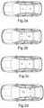
- the bright sound zone A is located at a front seat position and the dark sound zone B is located at a rear seat position. Examples of different bright and dark sound zones are shown in fig. 2 .
- the bright sound zone A is located at the front seats position and the dark sound zone B is located at the rear seats position.
- the bright sound zone A is located at the front left seat position.
- the first dark sound zone B1 is located at the front right seat position.
- the second dark sound zone B2 is located at the rear seats position.
- the bright sound zone A is located at the rear seats position and the dark sound zone B is located at the front seats position.
- the bright sound zone A is located at the rear left seat position.
- the first dark sound zone B1 is located at the front seats position.
- the second dark sound zone B2 is located at the rear right seat position.
- the provided sound is only desired to be heard by the person within the bright sound zone A. Under ideal conditions, it is desired that the persons within the dark sound zone(s) B, B1, B2, cannot hear the provided sound. However, in implementations, it is sufficient to keep a sound pressure level of the provided sound in the dark sound zone(s) as little as possible.
- SPL sound pressure level
- acoustic pressure level is a logarithmic measure of an effective pressure of a sound relative to a reference value.
- the sound pressure level, or shorted as pressure level, is typically measured in dB.
- ⁇ b and ⁇ d are sometimes used for referring to the bright and the dark sound zone, respectively.
- the following description is written for an audio signal provided to generate a desired sound in a bright sound zone and the notation ⁇ b is sometimes omitted.
- the dark sound zone ( ⁇ d ) should have as little sound leaking from the bright zone as possible.
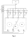
- Fig. 3 is a diagram of a method for creating a plurality of sound zones within an acoustic cavity.
- the audio data signal x ( n ) [ x, x, ... , x ] is provided for generating a desired sound in the bright sound zone A. That is, the provided audio data signal is the same for each one of the actuators 1 and the adaptive filters.
- a set of actuator generation coefficients kg k is used for controlling the actuators 1 to generate a desired sound in the bright sound zone A, while not generating excessive sounds in the dark sound zones B1, B2.
- a respective generation input signal is generated based on the set of actuator generation coefficients kg k and the provided audio data signal x ( n ).
- the set of actuator generation coefficients kg k may be in the form of an actuator generation matrix K g comprising a plurality of actuator generation coefficients kg k , wherein k is the number of actuators.
- the actuator generation matrix K g may be a diagonal matrix.
- K g K 1 ⁇ b ⁇ 0 ⁇ ⁇ ⁇ 0 ⁇ kg K ⁇ b
- the set of actuator generation coefficients kg k are chosen so that the expression [ S ] K g x can result in a desired sound in the bright sound zone A, while no excessive sounds in the dark sound zones B1, B2.
- [ S ] represents applying a respective secondary path from a respective actuator 1 to a respective error sensor 2.
- the generated sound is desired in the bright sound zone A and undesired in the dark sound zones B1, B2, the generated sound is a disturbance sound in the dark zones B1, B2.
- the actuators 1 may be lowly directive at low frequencies (about 20 to 300 Hz). Thus, it is not possible to generate a low frequency sound selectively in the bright sound zone A without exciting the whole acoustic cavity, including the dark sound zones B1, B2. It is however unnecessary to generate excessive sound in the dark sound zones B1, B2.
- the actuator generation coefficients kg k may only consist of zeros (0s) and ones (1s).
- An actuator generation coefficient being equal to zero (0) means that an actuator is not contributed in the generation of the desired sound in the bright sound zone A. That is, this actuator is not used for generating the desired sound in the bright sound zone A.
- An actuator generation coefficient being equal to one (1) means that an actuator is 100% contributed in the generation of the desired sound in the bright sound zone A.
- a subset of actuators may be selected for the generation of the desired sound in the bright sound zone A, by applying the coefficients kg k to the actuators 1.
- the coefficients kg k may be any real number.
- a set of actuator exclusion coefficients ke k is used for controlling the contribution of the actuators in cancelling the disturbance sound in the dark sound zones B1, B2, which is generated along with the generation of the desired sound in the bright sound zone A.
- the set of actuator exclusion coefficients ke k can be used for keeping the desired sound in the bright sound zone A unchanged as much as possible, in order to create a larger contrast between the bright sound zone A and dark sound zones B1, B2.
- Each of the adaptive filters receives the provided audio data signal x ( n ) as the input signal, and generates a respective output signal y ( n ) based on the input signal x ( n ) and the filter coefficient of the filter W k ( z ) .
- z is a notation referring to a z-transform.
- a respective exclusion input signal is generated based on the set of actuator exclusion coefficients ke k and the respective output signal y ( n ).
- a respective drive signal is generated based on the respective generation input signal and the respective exclusion input signal, such that each of the plurality of actuators 1 generates a respective acoustic output in response to the respective drive signal.
- the generated acoustic output is transmitted within the acoustic cavity to provide an individual sound in each sound zone.
- the set of actuator exclusion coefficients ke k may be in the form of an actuator exclusion matrix K e comprising a plurality of coefficients ke k , each for controlling one of the plurality of actuators 1.
- the actuator exclusion matrix K e may be a diagonal matrix.
- the coefficients ke i outside the main diagonal may all be zeros (0s).
- the actuator exclusion coefficients ke k on the main diagonal may be chosen so that a minimum squared value of a pressure level of a sound can be generated at a monitor location in the dark sound zones B1, B2, while keeping as much as possible the desired signal amplitude at a monitor location in the bright sound zone A.
- the actuator exclusion coefficient ke k may be zero (0), one (1), or any other real number.
- the error signals e [ e 1 , e 2 , ... , e M ] are generated by the plurality of the error sensors 2, each representing a respective sound detected by the respective error sensor 2.
- M represents the number of the error sensors.
- Each error signal is a sum of two different components.
- the first component is a disturbance signal, also known as a primary error signal in the active noise control theory.
- the second component is a cancelling signal, often known as a secondary error signal in the active noise control theory. In the dark sound zones, the disturbance signal is to be reduced as much as possible by the cancelling signal at the error sensor.
- the disturbance signal may be resulted by the respective generation input signal, which is generated based on the set of actuator generation coefficients kg k and the provided audio data signal x ( n ).
- the disturbance signal can be represented by the expression [ S ] K g x , wherein [ S ] represents applying the respective secondary path from the actuator 1 to the error sensor 2.
- S 32 refers to a secondary path from the third actuator to the second error sensor, as shown in fig. 3 .
- the cancelling signal may be resulted by the respective exclusion input signal, which is generated based on the set of actuator exclusion coefficients ke k and the respective output signal y ( n ).
- the cancelling signal can be represented by the expression [ S ] K e y , wherein [ S ] represents applying the respective secondary path from the actuator to the error sensor.
- a set of sensor weighting coefficients me m is used for controlling the contribution of each error sensor for reducing the disturbance sound in the dark sound zones B1, B2, which is generated along with the generation of the desired sound in the bright sound zone A.
- a respective weighted error signal is generated, based on the set of sensor weighting coefficients me m and the respective error signal e.
- the set of sensor weighting coefficients me m may be in the form of a sensor weighting matrix M e comprising a plurality of sensor weighting coefficients me m .
- the subscript m represents the number of the error sensors.
- the sensor weighting matrix M e may be a diagonal matrix.
- the sensor weighting coefficients me m outside the main diagonal may all be zeros (0s).
- the coefficient me m may be zero (0), one (1), or any other real number.
- the filter W k ( z ) associated to the actuator k may be updated by a standard Least Mean Square (LMS) method, or a standard Filtered Least Mean Square (FXLMS) method, described in e.g., Kuo, Active Noise Control Systems, Sen M. Kuo and Dennis Morgan. 1995. Active Noise Control Systems: Algorithms and DSP Implementations (1st ed.). John Wiley & Sons, Inc., New York, NY, USA .
- LMS Least Mean Square
- FXLMS Filtered Least Mean Square
- a respective updated filter is generated in order to reduce the respective weighted error signal, or the respective error signal.
- the updated filter may be the filter provided with at least one updated filter coefficient.
- the respective updated filter coefficient is generated based on the respective weighted error signal and a reference signal x ' km ( n ), to reduce the respective weighted error signal.
- the filter W k ( z ) is provided with more than one filter coefficient.
- the filter W k ( z ) may be provided with only one filter coefficient.
- w k,i are the filter coefficients of the filter W k .
- the weighted error signal e ' m ( n ) is obtained by application of the set of sensor weighting coefficients me m to the error signal e m .
- the reference signal x ' km ( n ) is generated based on the provided audio data signal x ( n ), the set of actuator exclusion coefficients ke k , and the secondary sound path model ⁇ representing acoustic transmission paths between each of the plurality of actuators 1 and each of the plurality of error sensor 2.
- the step size ⁇ may be a positive real number.
- the step size ⁇ may have a small magnitude relative to the filter coefficients.
- the step size ⁇ may be determined based on an amplitude of the audio data signal x ( n ).
- a typical value of ⁇ may be between 0 and 1.
- step size ⁇ is set to zero and the initial value of the filter coefficients of the filter W k ( z ) for each adaptive filter is set to be zero, then the adaptive filter is not actively involved in the system/method.
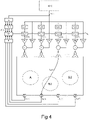
- Fig. 4 is another example of a method for creating a plurality of sound zones within an acoustic cavity.
- a respective static filter V k is provided for each adaptive filter.
- the method according to fig. 4 further comprises providing a respective static filter for filtering the provided audio data signal x ( n ), and generating a respective filtered signal in response to the provided audio data signal x ( n ).
- Each of the adaptive filters receives the respective filtered signal as the input signal, and generates a respective output signal y ( n ) based on the input signal and the filter coefficients.
- the respective static filter V k may be an independent filter outside the respective adaptive filter.
- the static filters V k ( z ) may be defined as a converged solution of the adaptive filter used in the method of fig. 3 for a broadband audio data signal x ( n ), e.g., a broadband noise, in the frequency range of interest.
- z is a notation referring to the z-transform.
- the static filter V k may be a vector of filter coefficients [ V k ,0 , V k ,1 , ... ] of the same length as the filter W k .
- a broadband noise also known as a wideband noise, is a noise signal whose energy is present over a wide audible range of frequencies, as opposed to a narrowband noise.
- Providing the static filter V k may make the filter coefficients of the filter W k ( z ) tend to be zero (0) for the broadband audio data signal x ( n ).
- the method of fig. 4 may be adapted for any broadband audio data signal x ( n ) with similar statistical characteristics as the data signal used to determine the static filters V k ( z ).
- the static filters V k ( z ) may be derived offline, e.g. during a calibration.
- the static filters V k ( z ) may be derived by simulation based on the secondary path model ⁇ representing the acoustic transmission paths from each of the plurality of actuators 1 and each of the plurality of error sensor 2.
- the acoustic transmission paths from each actuator to each error sensor may be simulated based on the secondary path model ⁇ .
- the static filters V k ( z ) may be the same or different for each sound zone.
- step size ⁇ is set to zero and the filter coefficient of the filter W k ( z ) for each adaptive filter is set to be zero, then the adaptive filter is not actively involved in the system/method, and only the static filters V k ( z ) are involved.
- the bright sound zone A is at the left front seat position, i.e. the driver's position.
- the two dark sound zones B1, B2 are at the front and rear passenger's position, respectively.
- Fig. 5b shows an example of the arrangement of the actuators and the error sensors in the car cockpit of fig. 5a for creating a plurality of sound zones.
- Six actuators 1-1, 1-2, ...,1-5, 1-6, and eight error sensors 2-1, 2-2, ..., 2-7, 2-8, are arranged within the car cockpit.
- Fig. 5c shows a simulation result of a contrast in sound pressure levels between the bright sound zone A and dark sound zones B1, B2, respectively, created by the method and the system using the actuators and error sensors arranged according to fig. 5b , for a broadband audio data signal.
- the x-axis represents a frequency value in Hz.
- Fig. 5c only shows the simulation result in a frequency range of 30 to 120 Hz.
- the y-axis represents a contrast of a sound pressure level (SPL) between two sound zones in dBA.
- SPL sound pressure level
- the short dashed line represents the contrast of sound pressure level between the sound zone A and the sound zone B1 of fig. 5a .
- the dotted line represents the contrast of sound pressure level between the sound zone A and the sound zone B2 of fig. 5a .
- the simulation is performed based on the measured transmission paths from the six actuators 1-1, 1-2, ...,1-5, 1-6, to the eight error sensors 2-1, 2-2, ..., 2-7, 2-8, as shown in fig. 5b .
- the set of actuator generation coefficients kg k the set of actuator exclusion coefficients ke k , and the set of sensor weighting coefficients me m used in the simulation can be expressed as the matrices K g , K e , and M e , respectively.
- the matrices K g , K e , and M e may be diagonal matrices comprising only elements of zeros (0s) and ones (1s).
- the simulation result shown in fig. 5c demonstrates that the sound zones created by the proposed method satisfy the perceptual requirement of at least 10 dB contrast, in the frequency range about 55-105 Hz.
- the contrast of sound pressure level (SPL) between the bright sound zone A and the dark sound zones B2, i.e. the contrast of sound pressure level between the driver position and the rear passenger position, is larger than that between the bright sound zone A and the dark sound zones B1, i.e. the contrast of sound pressure level between the driver position and the front passenger position.
- the coefficients used in the simulation are only zeros (0s) and ones (1s) to verify the inventive concept.
- the simulation result of fig. 5c can be further improved by having more finely adjusted coefficients rather than zeros (0s) or ones (1s).
- At least one set of the set of actuator generation coefficients kg k , the set of actuator exclusion coefficients ke k , and the set of sensor weighting coefficients me m may be determined by an optimization process.
- the optimization process may comprise: determining a plurality of monitor locations within the acoustic cavity; determining, for each of the acoustic transmission paths from each actuator to each monitor location, a respective transfer function; wherein at least one monitor location is arranged within each of the plurality of sound zones.
- the transfer function is defined as a mathematical relation between a sound source and a response, e.g., from an actuator to a monitor location, or an error sensor.
- An acoustic transmission path therebetween can be fully characterised based on the transfer function.
- the monitor locations may be determined to be at a head or an ear position of a person within a sound zone, such as a head or an ear position of a driver or a passenger of a vehicle.
- a monitor sensor e.g., a microphone, may be provided at each of the plurality of monitor locations.
- the respective transfer function may be determined by measuring a response at the monitor location.
- Said determining the respective transfer function by measuring may comprise: driving at least one of the plurality of actuators with a signal, preferably a white or pink noise signal, measuring a sound response at at least one of the plurality of monitor location.
- the monitor sensors may be used to measure a sound response at the head or the ear position of the person within the sound zone.
- the monitor sensors may be used only during the optimization process. That is, the monitor sensors may not be used for creating a plurality of sound zones within the acoustic cavity.
- one or more of the monitor sensors may also be used as the error sensors for creating a plurality of sound zones within the acoustic cavity.
- the respective transfer function may be determined by simulation. No monitor sensor is needed for simulation.
- the optimization process may comprise determining the set of actuator generation coefficients kg k for generating a first sound at a first monitor location arranged within the desired sound zone, wherein a first value representing the first sound is greater than a first threshold.
- the first value may be a squared pressure level of the first sound, expressed as ⁇ d monitors 2 > ⁇ b .
- the first threshold may be a value representing a minimal sound desired to be detected at a monitor location within the desire sound zone. That is, it is to determine the set of actuator generation coefficients kg k so that a big enough sound can be generated in the desired sound zone.
- the set of actuator generation coefficients kg k may be determined to maximise the first value. That is, to make the first value as great as possible.
- the optimization process may comprise determining the set of actuator generation coefficients kg k for generating a second sound at a second monitor location arranged outside the desired sound zone, wherein a second value representing the second sound is smaller than a second threshold.
- the second value may be a squared pressure level of the second sound, expressed as ⁇ d monitors 2 ⁇ ⁇ d .
- the second threshold may be a value representing a maximal sound to be detected at a monitor location outside the desire sound zone.
- the set of actuator generation coefficients kg k may be determined to minimise the second value. That is, to reduce the second value to a smallest possible amount.
- the coefficients me m and/or ke k may be chosen so that by an optimal control of a sound field at the error sensors, a minimum squared value of an error signal at the monitor positions can be achieved in the dark sound zones ⁇ d , while keeping as much as possible the desired signal amplitude at the monitor positions in the bright sound zone ⁇ b .
- the optimization process may comprise determining a set of coefficients me m and/or ke k that minimize the following function ⁇ e monitors 2 ⁇ ⁇ d + ⁇ ⁇ e monitors ⁇ d monitors 2 ⁇ ⁇ b .
- ⁇ e monitors 2 ⁇ ⁇ d may refer to a squared pressure level of a sound in the dark sound zones, which is generated by the actuators, along with the generation of the desired sound in the bright sound zone A.
- the sound may represent a resulting sound generated outside the desired sound zone, by the plurality of the actuators. That is, the sound is undesired, which needs to be cancelled or at least reduced.
- minimising ⁇ e monitors 2 ⁇ ⁇ d means to minimise the resulting sound generated outside the desired sound zone.
- 2 > ⁇ b may refer to an amount of sound reduction within the bright sound zone A.
- 2 > ⁇ b may represent an amount of a sound reduction in the desired sound zone, caused by a sound generated for cancelling the third sound.
- 2 > ⁇ b means to keep the sound reduction in the bright zone as little as possible.
- ⁇ may be a weighting factor which weighs these two aspects.
- ⁇ may be used for controlling how much a bright sound zone may be affected by the method/system. ⁇ may be any positive real number.
- Fig. 6a is an example of a process diagram for determining the set of actuator generation coefficients kg k , the set of actuator exclusion coefficients ke k , and the set of sensor weighting coefficients me m , for a sound zone.
- a secondary path model S representing the acoustic transmission paths from all potential actuator positions to all potential error sensor positions and all monitor positions within the acoustic cavity are determined, by measuring or simulation.
- Fig. 6b is an example illustrating the potential positions for actuators 1, for error sensors 2, and for monitor sensors 6, within a vehicle, as in S1.
- the monitor sensors may be provided at a head or ear position of a person, such as a driver or a passenger, as shown in fig. 6b .
- the actuator positions, the error sensor positions are determined for an optimal control for all sound zones within the acoustic cavity, based on the determined secondary path model S.
- the actuators and error sensors may be provided in the acoustic cavity according to the respective determined positions.
- Fig. 6c is an example illustrating the vehicle of fig. 6b with the actuators 1 and error sensors 2 provided on the determined positions.
- the set of actuator generation coefficients kg k , the set of actuator exclusion coefficients ke k , and the set of sensor weighting coefficients me m are determined for each sound zone.
- the coefficients determined in S3 are stored in a storage unit 5.
- the storage unit 5 may be provided within the vehicle, as shown in fig. 6d .
- the storage unit 5 may be provided outside the vehicle, e.g., as a cloud storage unit.
- Fig. 7 is an example of a method for creating a plurality of sound zones within an acoustic cavity. Comparing with fig. 4 , the method further comprises determining a desired sound zone, and retrieving the determined set of actuator generation coefficients kg k , the determined set of actuator exclusion coefficients ke k , and the determined set of sensor weighting coefficients me m , based on the determined sound zone, from e.g., the storage unit 5.
- the storage unit 5 may be provided within the vehicle, or outside the vehicle.
Description
- The present document relates to a method and system for creating a plurality of sound zones within an acoustic cavity. In particular, it relates to a method and system for creating a plurality of individual sound zones within a vehicle cockpit.
- Along with recent technological development, the time spent in a vehicle has become a mixed sound experience for the driver and the passengers. With the development of in-car connectivity, autonomous and shared driving, the vehicle cockpit is filled by chaotically mixed sounds, e.g., targeted vocal messages, hands-free calls, broadcastings from a vehicle audio system, individual screen programs, video games, voice messages of a navigation system, etc. Thus, an individual sound zone within a vehicle cockpit, in which each passenger/driver is able to choose his own audio content with a reduced disturbance, is desired.
- Methods for creating individual sound zones or sound bubbles within an acoustic cavity have been widely studied, as one of the upcoming key audio developments for vehicles.
- One method is to create a sound isolation between the different sound zones. For example, it is known that headrest speakers or directional speakers can be used to generate and control a localized sound in one sound zone. Cross-talk cancellation means can be added in another sound zone to reduce the unwanted noise which leaks from the one sound zone.
-
US 2017/034623 A1 relates to a system and method for generating a sound wave field around a listening position and discloses a method for creating a plurality of sound zones within an acoustic cavity using a plurality of actuators and associated adaptive filters. A plurality of error sensors are provided for generating a plurality of error signals. The method further comprises the provision of an audio data signal for generating a desired sound in a desired sound zone of the plurality of sound zones. A set of actuator generation coefficients, a set of actuator exclusion coefficients, and a set of sensor weighting coefficients are provided. For each actuator a respective drive signal is provided based on an input signal. To this end, a respective generation input signal is generated based on the provided audio data signal, generating a respective weighted error signal based on the set of sensor weighting coefficients and the respective error signal, generating a reference signal based on the provided audio data signal and a secondary sound path model representing a plurality of acoustic transmission paths from each of the plurality of actuators to each of the plurality of error sensor. The updated filter coefficients are then generated based on the respective weighted error signal and the reference signal to reduce the respective weighted error signal. -
US 2019/014430A1 relates to a loudspeaker-room system. CHUNG HANWOOK ET AL: "Adaptive Crosstalk Cancellation Using Common Acoustical Pole and Zero (CAPZ) Model-Common Pole Estimation", AES CONVENTION 131; 19 October 2011 (2011-10-19), relates to adaptive crosstalk cancellation. BETLEHEM TERENCE ET AL: "Personal Sound Zones: Delivering interface-free audio to multiple listeners", IEEE SIGNAL PROCESSING MAGAZINE, IEEE SERVICE CENTER, PISCATAWAY, NJ, US, vol. 32, no. 2, 1 March 2015 (2015-03-01 ), pages 81-91, ISSN: 1053-5888, DOI: 10.1 109/MSP.2014.2360707 relates to establishing personal sound zones. However, such localised solutions normally need to have the speakers and/or sensors placed within, or at least in a proximity of each sound zone. This arrangement of the speakers and/or sensors can be difficult to implement depending on the specific design of the acoustic cavity. If the speakers and/or sensors cannot be arranged on the optimal locations, the isolation effect will be degraded, and the disturbance cannot be reduced efficiently for certain sound zones. - Furthermore, such localised solutions cannot provide a wideband sound isolation since only when the wavelength of a sound is smaller than a distance between two sound zones, typically over 300 Hz, the localised solutions are effective. Thus, a certain part of the wideband sound will leak between the sound zones, which will undoubtedly degrade the sound isolation between the sound zones.
- Thus, there is a need to provide a better sound isolation between the sound zones in order to generate an enhanced feeling of immersiveness for a person within each sound zone, e.g., the driver/passenger of the vehicle. There is also a need to provide a more flexible arrangement of the speakers and sensors within an acoustic cavity for creating a plurality of sound zones.
- It is an object of the present disclosure, to provide a new method and system for creating a plurality of sound zones within an acoustic cavity, which eliminates or alleviates at least some of the disadvantages of the prior art.
- Further, there is another object of the present disclosure, to provide a new method and system for creating a plurality of sound zones within an acoustic cavity, which can improve, or at least complement the prior art.
- The invention is defined by the appended independent claims. Embodiments are set forth in the appended dependent claims, and in the following description and drawings.
- According to a first aspect, there is provided a method for creating a plurality of sound zones within an acoustic cavity. The method comprises: providing a plurality of actuators within the acoustic cavity, each for generating a respective acoustic output in response to a respective drive signal, providing, for each of the plurality of actuators, an adaptive filter for receiving a respective input signal, and generating a respective output signal, providing, for each of the adaptive filters, at least one filter coefficient, providing a plurality of error sensors within the acoustic cavity, each for generating a respective error signal e, representing a respective sound detected by the respective error sensor, providing an audio data signal x (n) for generating a desired sound in a desired sound zone of the plurality of sound zones, and providing, for the desired sound zone, a set of actuator generation coefficients kgk , a set of actuator exclusion coefficients kek, wherein k refers to a kth actuator, k=1, 2, 3..., and a set of sensor weighting coefficients mem wherein m refers to a mth error sensor, m=1, 2, 3... Wherein each of the adaptive filters receives the provided audio data signal x ( n ) as the input signal, and generates a respective output signal y ( n ) based on the input signal and the at least one filter coefficient. The method further comprises providing, for each of the plurality of actuators, the respective drive signal for generating the respective acoustic output, comprising: generating a respective generation input signal, based on the set of actuator generation coefficients kgk and the provided audio data signal x ( n ); generating a respective exclusion input signal, based on the set of actuator exclusion coefficients kek and the respective output signal y ( n ); generating the respective drive signal based on the respective generation input signal and the respective exclusion input signal. The method further comprises: generating, for each of the adaptive filters, at least one respective updated filter coefficient, comprising: generating a respective weighted error signal, based on the set of sensor weighting coefficients mem and the respective error signal e ; generating a reference signal x' ( n ) based on the provided audio data signal x ( n ), the set of actuator exclusion coefficients kek, and a secondary sound path model Ŝ representing a plurality of acoustic transmission paths from each of the plurality of actuators to each of the plurality of error sensor; generating the respective updated filter coefficient based on the respective weighted error signal and the reference signal x' ( n ), to reduce the respective weighted error signal.
- A sound zone may be a volume within the acoustic cavity, typically around a head or ears of a person. In a vehicle, the sound zone may be a volume corresponds to an individual seat position, e.g., a front seat position, a rear seat position.
- An acoustic cavity may be a substantially closed volume, within which acoustic sounds can be transmitted and reflected, e.g., a cockpit of an automotive, a truck, a train or an airplane.
- The provided audio data signal may be a signal representing a noise, e.g., a noise from an engine of a vehicle or a road noise.
- Each adaptive filter may have one filter coefficient. Alternatively, each adaptive filter may have more than one filter coefficient. In the present application, more than one filter coefficient is provided for each adaptive filter.
- In contrast to a medium frequency, typically from about 300 to 2000 Hz, or a high frequency, typically from about 2000 to 20000 Hz, part of a sound, a low frequencies part of the sound, typically from about 20 to 300 Hz, cannot be handled properly by the known methods, for the following reasons.
- Firstly, the headrest speakers and directional speakers are not designed to work in the low frequency range.
- Secondly, a low frequency sound has a larger wavelength in relation to a size of an acoustic cavity, e.g., a vehicle cockpit, comparing with the medium and high frequency sounds. Due to the larger wavelength, the low frequency sounds are coupled to acoustic resonances of the acoustic cavity and therefore are difficult to handle locally within a part of the acoustic cavity.
- Consequently, the known individual sound zones in the acoustic cavity are merely narrowband sound zones, which comprises only the medium and high frequency sounds. The low frequency sounds are globally existing within the cavity. That is, the known individual sound zones don't have an individual low frequency sound.
- The inventive concept is to create a plurality of sound zones within an acoustic cavity, such as a vehicle cockpit, wherein each sound zone is provided with an individual desired sound, including a low frequency sound.
- The inventive concept comprises: 1) generating a low frequency (around 20 to 300 Hz) sound, or a low frequency part of a sound, for both a sound zone which needs the generated sound, e.g., a bright sound zone, and a sound zone which does not need it, e.g., a dark sound zone; and 2) cancelling or at least reducing the generated sound in the sound zone which does not need it. The inventive concept can be implemented by a plurality of distributed actuators and error sensors, a respective adaptive filter provided for each actuator. Coefficients may be used to control the contribution of each actuator and each sensor in generation and cancellation of a sound for each sound zone.
- Thus, the low frequency sound, or the low frequency part of the sound can be individually created for at least two different sound zones within the acoustic cavity, by a global approach.
- Since more than one actuator and error sensor may contribute to creating the individual sound zones, the actuators and error sensors do not need to be placed within or in a proximity of the sound zones. Thus, the arrangement of the actuators and/or error sensors can be more flexible.
- Further, each sound zone within the acoustic cavity may be provided with an individual low frequency sound or an individual low frequency part of a sound. A feeling of immersiveness for the person within the sound zone will be enhanced, especially for music experiences.
- Moreover, since the individual sound zones are created by a global approach instead of performing localised sound generation/cancellation for each sound zone, the sound leakages between different sound zones can be handled more efficiently such that a better sound isolation between different sound zones can be achieved.
- The invention can be implemented in a vehicle cockpit, or any other acoustic cavity, wherein the notion of low frequencies is relative to the characteristic size of the acoustic cavity, such as a cockpit of an automobile, a truck, a train or an airplane.
- The error sensor may be a microphone. The actuator may be a loudspeaker or a vibrating panel.
- As the audio signals for different sounds are incoherent to each other and the processes involved are linear, assuming that the actuators work in their linear domain, several systems/methods can be superposed without interfering with each other. Thus, when a few bright sound zones are desired for different sounds, a plurality of systems may work in parallel for creating different sounds for the bright sound zones.
- Active noise control (ANC) is a method known for reducing unwanted low frequency noise, e.g., an engine noise of a vehicle, and a road noise, by an addition of a second sound specifically designed to cancel the unwanted sound.
- A typical ANC system in a vehicle comprises a controller, e.g., a digital signal processor (DSP), and a distributed system of actuators and sensors, whose positions and characteristics are selected for optimally performing in a low frequency range, typically from 20 to 300 Hz. The actuators may be loudspeakers or vibrating panels. The sensors may be microphones.
- The unwanted sound can be described as a pressure wave having an amplitude and a phase. The ANC system can emit a wave with an equal amplitude, but a phase of 180°, i.e. an inverted phase, or anti-phase, of the unwanted wave, to cancel the unwanted wave.
- Likewise, the system for creating a plurality of sound zones can work in parallel with any existing ANC system dedicated for controlling, e.g., an engine noise and/or a road noise, without interfering with the ANC system.
- The method/system can also be used for active noise control. For example, the method/system can also be used for active noise control of an engine noise or a road noise.
- At least one set of the set of actuator generation coefficients kgk , the set of actuator exclusion coefficients kek, and the set of sensor weighting coefficients mem, may be determined by an optimization process.
- The optimization process may comprise: determining a plurality of monitor locations within the acoustic cavity; determining, for each of a plurality of acoustic transmission paths from each of the plurality of actuators to each of the plurality of monitor locations, a respective transfer function; wherein at least one monitor location may be arranged within each of the plurality of sound zones.
- The transfer function may be a mathematical relation between a sound source and a response, e.g., from an actuator to a monitor location, or an error sensor. An acoustic transmission path therebetween can be fully characterised based the transfer function.
- The optimization process may further comprise: providing a monitor sensor at each of the plurality of monitor locations, and determining the respective transfer function by measuring a response at the provided monitor sensor.
- The monitor sensor may be a microphone.
- Said determining the respective transfer function by measuring may comprise: driving at least one of the plurality of actuators with a signal, preferably a white or pink noise signal, and measuring a response by the provided monitor sensor.
- The optimization process may comprise: determining the respective transfer function by simulation.
- The optimization process may comprise: determining the set of actuator generation coefficients kgk for generating a first sound at a first monitor location arranged within the desired sound zone, wherein a first value representing the first sound may be greater than a first threshold. Preferably, the first value may be a squared pressure level of the first sound, expressed as

- The first threshold may be a value representing a minimal sound desired to be detected at a monitor location within the desire sound zone.
- It is to determine the set of actuator generation coefficients kgk so that a loud enough sound can be generated in the desired sound zone.
- Preferably, the set of actuator generation coefficients kgk may be determined to maximise the first value. That is, to make the first value as great as possible.
- The optimization process may comprise: determining the set of actuator generation coefficients kgk for generating a second sound at a second monitor location arranged outside the desired sound zone, wherein a second value representing the second sound may be smaller than a second threshold. Preferably, the second value may be a squared pressure level of the second sound, expressed as

- The second threshold may be a value representing a maximal sound to be detected at a monitor location outside the desire sound zone.
- It is to determine the set of actuator generation coefficients kgk so that a small enough sound can be generated outside the desired sound zone. That is, it is to generate less sound outside the desired sound zone, which needs to be cancelled.
- Preferably, the set of actuator generation coefficients kgk may be determined to minimise the second value. That is, to reduce the second value to a smallest possible amount.
- The optimization process may comprise: determining the set of actuator exclusion coefficients kek, and the set of sensor weighting coefficients mem, by minimising the following function

- Wherein

- The third sound may represent a resulting sound generated outside the desired sound zone, by the plurality of the actuators. That is, the third sound may be undesired, which needs to be cancelled or at least reduced. Thus, minimising

- α < |emonitors - dmonitors |2> σb may represent an amount of a sound reduction in the desired sound zone, caused by a sound generated for cancelling the third sound. Thus, minimising α < |emonitors - dmonitors |2 > σb means to keep the sound reduction in the bright zone as little as possible.
- α may be a coefficient that weighs the two aspects.
- The method for creating a plurality of sound zones within an acoustic cavity may further comprise providing, for each of the plurality of sound zones, a respective set of actuator generation coefficients kgk , a respective set of actuator exclusion coefficients kek, and a respective set of sensor weighting coefficients mem.
- At least one set of the provided set of actuator generation coefficients kgk , the set of actuator exclusion coefficients kek, and the set of sensor weighting coefficients mem, may be stored in a storage unit.
- The storage unit may be provided within or outside the acoustic cavity.
- The method for creating a plurality of sound zones within an acoustic cavity may further comprise providing a respective static filter for receiving the provided audio data signal x ( n ) , and generating a respective filtered signal in response to the provided audio data signal x ( n ). Each of the adaptive filters may receive the respective filtered signal as the input signal, and may generate a respective output signal y ( n ) based on the input signal and the at least one filter coefficient.
- Each of the adaptive filters may comprise a respective static filter, for receiving the provided audio data signal x ( n ) , and generating a respective filtered signal in response to the provided audio data signal x ( n ). Each of the adaptive filters may receive the respective filtered signal as the input signal, and may generate a respective output signal y ( n ) based on the input signal and the at least one filter coefficient.
- The respective static filter may be determined by a calibration or by a simulation.
- The respective generation input signal may be generated by applying the set of actuator generation coefficients kgk to the provided audio data signal x ( n ).
- The respective exclusion input signal may be generated by applying the set of actuator exclusion coefficients kek to the respective output signal y ( n ).
- The respective weighted error signal may be generated by applying the set of sensor weighting coefficients mem to the respective error signal e .
- The reference signal x' ( n ) may be generated by applying the secondary sound path model Ŝ, and applying the set of actuator exclusion coefficients kek to the provided audio data signal x ( n ),

- The provided audio data signal x ( n ) may have a frequency range of 20 to 400 Hz, preferably 20-300 Hz, more preferably 30-200 Hz, most preferably 50-150 Hz.
- The generated at least one respective updated filter coefficient at a time step n+1 may be expressed as

- Wherein Wk (n) may represent the respective filter coefficient at a time step n. x' km (n) may represent a reference audio signal. e' m (n) may represent the weighted error signal. µ may be a step size.
- The reference signal x ' km (n) may be generated based on the provided audio data signal x ( n ), the set of actuator exclusion coefficients kek, and the secondary sound path model Ŝ.
- The reference signal x ' km (n) may be expressed as:

- The method for creating a plurality of sound zones within an acoustic cavity may further comprise updating at least one set of the set of actuator generation coefficients kgk , the set of actuator exclusion coefficients kek, and the set of sensor weighting coefficients mem, for the desired sound zone.
- Said updating may be performed by a learning process.
- According to a second aspect, there is provided a system for creating a plurality of sound zones within an acoustic cavity. The system comprises: a plurality of actuators within the acoustic cavity, each configured to generate a respective acoustic output in response to a respective drive signal, an adaptive filter operatively connected to each of the plurality of actuators, configured to receive a respective input signal, and generate a respective output signal, wherein each of the adaptive filters is provided with at least one filter coefficient, a plurality of error sensors within the acoustic cavity, each configured to generate a respective error signal e , representing a respective sound detected by the respective error sensor, a control unit, configured to: receive an audio data signal x ( n ) for generating a desired sound in a desired sound zone of the plurality of sound zones, provide, for the desired sound zone, a set of actuator generation coefficients kgk , a set of actuator exclusion coefficients kek, wherein k refers to a kth actuator, k=1, 2, 3..., and a set of sensor weighting coefficients mem wherein m refers to a mth error sensor, m=1, 2, 3...; wherein each of the adaptive filters is configured to receive the provided audio data signal x ( n ) as the input signal, and to generate a respective output signal y ( n ) based on the input signal and the at least one filter coefficient. The control unit is further configured to: provide, for each of the plurality of actuators, the respective drive signal for generating the respective acoustic output, wherein the control unit is further configured to: generate a respective generation input signal, based on the set of actuator generation coefficients kgk and the provided audio data signal x ( n ); generate a respective exclusion input signal, based on the set of actuator exclusion coefficients kek and the respective output signal y ( n ); generate the respective drive signal based on the respective generation input signal and the respective exclusion input signal. The control unit is further configured to: generate, for each of the adaptive filters, at least one respective updated filter coefficient, wherein the control unit is further configured to: generate a respective weighted error signal, based on the set of sensor weighting coefficients mem and the respective error signal e; generate a reference signal x' ( n ) based on the provided audio data signal x ( n ), the set of actuator exclusion coefficients kek, and a secondary sound path model S representing a plurality of acoustic transmission paths from each of the plurality of actuators to each of the plurality of error sensor; generate the respective updated filter coefficient based on the respective weighted error signal and the reference signal x' ( n ), to reduce the respective weighted error signal.
- The actuator may be a loudspeaker, or a vibrating panel. The error sensor may be a microphone.
-
-
Fig. 1 is a schematic view of a system for creating a plurality of sound zones within a car cockpit. -
Figs 2a-2d are examples of different sound zones within a car cockpit. -
Fig. 3 is an example of a diagram of a method for creating a plurality of sound zones within an acoustic cavity. -
Fig. 4 is an example of a diagram of a method for creating a plurality of sound zones within an acoustic cavity. -
Fig. 5a is an example of different sound zones within a car cockpit. -
Fig. 5b is an example of arrangement of actuators and error sensors in the car cockpit offig. 5a . -
Fig. 5c is a simulation result of a contrast in sound level between a driver sound zone and a front/rear passenger(s) sound zone infig. 5a . -
Fig. 6a is an example of a process diagram for determining a set of actuator generation coefficients kgk, a set of actuator exclusion coefficients kek, and a set of sensor weighting coefficients mem, for a sound zone. -
Fig. 6b-6d are examples of a vehicle provided with actuators and sensors according to the process diagram offig. 6a . -
Fig. 7 is an example of a diagram of a method for creating a plurality of sound zones within an acoustic cavity. -
Fig. 1 is a schematic view of a system for creating a plurality of sound zones within a car cockpit. As shown infig. 1 , the system comprises acontrol unit 3, threeactuators 1 in the form of loudspeakers, and fiveerror sensors 2 in the form of microphones. - The
control unit 3 may comprise a processor, a DSP, a CPU. Thecontrol unit 3 may comprise a storage unit (not shown). -
Fig. 1 also shows anaudio unit 4 for providing an audio data signal for generating a desired sound in a desired sound zone of the plurality of sound zones. Theaudio unit 4 may be an in-vehicle infotainment (IVI) system or an In-car entertainment (ICE) system. - The IVI/ICE system may refer to a vehicle system that combines entertainment and information delivery to drivers and passengers. The IVI/ICE system may use audio/video (A/V) interfaces, touchscreens, keypads and other types of devices to provide these types of services.
- The
control unit 3 and theaudio unit 4 may be two separate units, as shown infig. 1 . Alternatively, thecontrol unit 3 and theaudio unit 4 may be combined as one unit. For example, thecontrol unit 3 may be implemented in theaudio unit 4. - In
fig. 1 , all theerror sensors 2 are connected in series to thecontrol unit 3. Theactuators 1 are connected in parallel to thecontrol unit 3. However, these ways of connections shown infig. 1 are only examples for illustration. For example, at least two of theerror sensors 2 may be connected in parallel to thecontrol unit 3. For example, at least two of theactuators 1 may be connected in series to thecontrol unit 3. Any one of the connection links between theerror sensors 2, between theactuators 1, between thecontrol unit 3 to anactuator 1, or to anerror sensor 2, may be wired or wireless. - A sound zone may be a volume within an acoustic cavity. For example, a sound zone may be a volume around a head and/or an ear of a driver or a passenger. Sound zones within a vehicle cockpit may correspond to different seating positions or a group of seating positions in the vehicle.
- A bright sound zone may be a sound zone, in which a provided sound is desired to be heard by a person, e.g., a driver or a passenger, within the sound zone.
- The volume outside the bright sound zone may be one or a plurality of different dark sound zone(s), in which the provided sound is undesired and not want to be heard by a person within the dark sound zone(s).
- In
fig. 1 , there are two different sound zones A, B. The bright sound zone A is located at a front seat position and the dark sound zone B is located at a rear seat position. Examples of different bright and dark sound zones are shown infig. 2 . - In
fig. 2a , the bright sound zone A is located at the front seats position and the dark sound zone B is located at the rear seats position. - In
fig. 2b , the bright sound zone A is located at the front left seat position. The first dark sound zone B1 is located at the front right seat position. The second dark sound zone B2 is located at the rear seats position. - In
fig. 2c , the bright sound zone A is located at the rear seats position and the dark sound zone B is located at the front seats position. - In
fig. 2d , the bright sound zone A is located at the rear left seat position. The first dark sound zone B1 is located at the front seats position. The second dark sound zone B2 is located at the rear right seat position. - The provided sound is only desired to be heard by the person within the bright sound zone A. Under ideal conditions, it is desired that the persons within the dark sound zone(s) B, B1, B2, cannot hear the provided sound. However, in implementations, it is sufficient to keep a sound pressure level of the provided sound in the dark sound zone(s) as little as possible.
- It is known that sound pressure level (SPL) or acoustic pressure level is a logarithmic measure of an effective pressure of a sound relative to a reference value. The sound pressure level, or shorted as pressure level, is typically measured in dB.
- A difference in a pressure level between the bright and dark sound zone can be quantified in terms of a contrast, typically expressed as:

- In the present application, σb and σd are sometimes used for referring to the bright and the dark sound zone, respectively. The following description is written for an audio signal provided to generate a desired sound in a bright sound zone and the notation σb is sometimes omitted.
- Various perceptual experiments have indicated that a required contrast between the bright and the dark sound zone should be between 10 to 40 dB. The experiments can be found, for example in Francombe, J., Mason, R., Dewhirst, M., and Bech, S. (2012). "Determining the threshold of acceptability for an interfering audio programme," in Proceedings of the 132nd AES Convention, Budapest, Hungary, 26-29 April 2012 ; and Baykaner, K., Hummersone, C., Mason, R., and Bech, S. (2013). "The prediction of the acceptability of auditory interference based on audibility," in Proceedings of the 52nd AES International Conference Guildford, UK, 2-4 September 2013 .
- Thus, in order to achieve a larger contrast, it is desired to have as little pressure level as possible in the dark sound zone σd . That is, the dark sound zone (σd should have as little sound leaking from the bright zone as possible.
-
Fig. 3 is a diagram of a method for creating a plurality of sound zones within an acoustic cavity. - The audio data signal x ( n ) = [x, x, ... , x] is provided for generating a desired sound in the bright sound zone A. That is, the provided audio data signal is the same for each one of the
actuators 1 and the adaptive filters. - A set of actuator generation coefficients kgk is used for controlling the
actuators 1 to generate a desired sound in the bright sound zone A, while not generating excessive sounds in the dark sound zones B1, B2. - For each of the plurality of
actuators 1, a respective generation input signal is generated based on the set of actuator generation coefficients kgk and the provided audio data signal x ( n ). - The set of actuator generation coefficients kgk may be in the form of an actuator generation matrix Kg comprising a plurality of actuator generation coefficients kgk, wherein k is the number of actuators.
- The actuator generation matrix Kg may be a diagonal matrix. A main diagonal, also known as a principal diagonal, a primary diagonal, a leading diagonal, or a major diagonal, of a matrix M is a collection of elements Mi, j wherein i equals to j (i=j). All off-diagonal elements are zero in a diagonal matrix. That is, the actuator generation matrix Kg may be a diagonal matrix, wherein the coefficients kgk outside the main diagonal are all zeros (0s).
- An example of the actuator generation matrix Kg may be

- The set of actuator generation coefficients kgk are chosen so that the expression [ S ] Kgx can result in a desired sound in the bright sound zone A, while no excessive sounds in the dark sound zones B1, B2. [S] represents applying a respective secondary path from a
respective actuator 1 to arespective error sensor 2. - Since the generated sound is desired in the bright sound zone A and undesired in the dark sound zones B1, B2, the generated sound is a disturbance sound in the dark zones B1, B2.
- The
actuators 1 may be lowly directive at low frequencies (about 20 to 300 Hz). Thus, it is not possible to generate a low frequency sound selectively in the bright sound zone A without exciting the whole acoustic cavity, including the dark sound zones B1, B2. It is however unnecessary to generate excessive sound in the dark sound zones B1, B2. - In a simple form, the actuator generation coefficients kgk may only consist of zeros (0s) and ones (1s). An actuator generation coefficient being equal to zero (0) means that an actuator is not contributed in the generation of the desired sound in the bright sound zone A. That is, this actuator is not used for generating the desired sound in the bright sound zone A. An actuator generation coefficient being equal to one (1) means that an actuator is 100% contributed in the generation of the desired sound in the bright sound zone A.
- Thus, a subset of actuators may be selected for the generation of the desired sound in the bright sound zone A, by applying the coefficients kgk to the
actuators 1. - In a complex form, the coefficients kgk may be any real number.
- A set of actuator exclusion coefficients kek is used for controlling the contribution of the actuators in cancelling the disturbance sound in the dark sound zones B1, B2, which is generated along with the generation of the desired sound in the bright sound zone A. The set of actuator exclusion coefficients kek can be used for keeping the desired sound in the bright sound zone A unchanged as much as possible, in order to create a larger contrast between the bright sound zone A and dark sound zones B1, B2.
- Each of the adaptive filters receives the provided audio data signal x ( n ) as the input signal, and generates a respective output signal y ( n ) based on the input signal x ( n ) and the filter coefficient of the filter Wk (z). Wherein z is a notation referring to a z-transform. For each of the plurality of
actuators 1, a respective exclusion input signal is generated based on the set of actuator exclusion coefficients kek and the respective output signal y ( n ). - For each of the plurality of
actuators 1, a respective drive signal is generated based on the respective generation input signal and the respective exclusion input signal, such that each of the plurality ofactuators 1 generates a respective acoustic output in response to the respective drive signal. - The generated acoustic output is transmitted within the acoustic cavity to provide an individual sound in each sound zone.
- The set of actuator exclusion coefficients kek may be in the form of an actuator exclusion matrix Ke comprising a plurality of coefficients kek, each for controlling one of the plurality of
actuators 1. - The actuator exclusion matrix Ke may be a diagonal matrix. The coefficients kei outside the main diagonal may all be zeros (0s).
- The actuator exclusion coefficients kek on the main diagonal may be chosen so that a minimum squared value of a pressure level of a sound can be generated at a monitor location in the dark sound zones B1, B2, while keeping as much as possible the desired signal amplitude at a monitor location in the bright sound zone A.
- An example of the actuator exclusion matrix Ke may be

- The actuator exclusion coefficient kek may be zero (0), one (1), or any other real number.
- The error signals e = [e1, e 2, ... , eM ] are generated by the plurality of the
error sensors 2, each representing a respective sound detected by therespective error sensor 2. M represents the number of the error sensors. - Each error signal is a sum of two different components. The first component is a disturbance signal, also known as a primary error signal in the active noise control theory. The second component is a cancelling signal, often known as a secondary error signal in the active noise control theory. In the dark sound zones, the disturbance signal is to be reduced as much as possible by the cancelling signal at the error sensor.
- The ideal situation is that the two components are totally cancelled by each other, to result in the error signal as zero. However, in implementations, it is sufficient to keep an error signal as little as possible, i.e. to achieve a minimum error signal.
- The disturbance signal may be resulted by the respective generation input signal, which is generated based on the set of actuator generation coefficients kgk and the provided audio data signal x ( n ). The disturbance signal can be represented by the expression [ S ] Kgx , wherein [S] represents applying the respective secondary path from the
actuator 1 to theerror sensor 2. For example, S32 refers to a secondary path from the third actuator to the second error sensor, as shown infig. 3 . - The cancelling signal may be resulted by the respective exclusion input signal, which is generated based on the set of actuator exclusion coefficients kek and the respective output signal y ( n ). The cancelling signal can be represented by the expression [ S ] Key, wherein [S] represents applying the respective secondary path from the actuator to the error sensor.
- The error signal may be represented by the expression:

- A set of sensor weighting coefficients mem is used for controlling the contribution of each error sensor for reducing the disturbance sound in the dark sound zones B1, B2, which is generated along with the generation of the desired sound in the bright sound zone A.
- A respective weighted error signal is generated, based on the set of sensor weighting coefficients mem and the respective error signal e.
- The weighted error signal can be expressed as:

- The set of sensor weighting coefficients mem may be in the form of a sensor weighting matrix Me comprising a plurality of sensor weighting coefficients mem. The subscript m represents the number of the error sensors.
- The sensor weighting matrix Me may be a diagonal matrix. The sensor weighting coefficients mem outside the main diagonal may all be zeros (0s).
- The coefficient mem may be zero (0), one (1), or any other real number.
- An example of the sensor weighting coefficients Me may be

- The weighted error signal may also be expressed as:

- The filter Wk (z) associated to the actuator k may be updated by a standard Least Mean Square (LMS) method, or a standard Filtered Least Mean Square (FXLMS) method, described in e.g., Kuo, Active Noise Control Systems, Sen M. Kuo and Dennis Morgan. 1995. Active Noise Control Systems: Algorithms and DSP Implementations (1st ed.). John Wiley & Sons, Inc., New York, NY, USA .
- A respective updated filter is generated in order to reduce the respective weighted error signal, or the respective error signal. The updated filter may be the filter provided with at least one updated filter coefficient.
- The respective updated filter coefficient is generated based on the respective weighted error signal and a reference signal x'km (n), to reduce the respective weighted error signal.
- The filter Wk (z) at a time step n can be expressed as:

- Here the filter Wk (z) is provided with more than one filter coefficient. Alternatively, the filter Wk (z) may be provided with only one filter coefficient. Wherein wk,i are the filter coefficients of the filter Wk . The updated filter Wk (z) at a time step n+1 can be expressed as:

- e' m (n) represents the weighted error signal; and
- µ is a step size.
- The weighted error signal e' m (n) is obtained by application of the set of sensor weighting coefficients mem to the error signal em .
- The reference signal x'km (n) is generated based on the provided audio data signal x ( n ), the set of actuator exclusion coefficients kek, and the secondary sound path model Ŝ representing acoustic transmission paths between each of the plurality of
actuators 1 and each of the plurality oferror sensor 2. The reference signal x'km (n) can be expressed as:
- The step size µ may be a positive real number. The step size µ may have a small magnitude relative to the filter coefficients. The step size µ may be determined based on an amplitude of the audio data signal x ( n ). A typical value of µ may be between 0 and 1.
- If the step size µ is set to zero and the initial value of the filter coefficients of the filter Wk (z) for each adaptive filter is set to be zero, then the adaptive filter is not actively involved in the system/method.
-
Fig. 4 is another example of a method for creating a plurality of sound zones within an acoustic cavity. - Comparing with the diagram of
fig. 3 , a respective static filter Vk is provided for each adaptive filter. The method according tofig. 4 further comprises providing a respective static filter for filtering the provided audio data signal x ( n ), and generating a respective filtered signal in response to the provided audio data signal x ( n ). Each of the adaptive filters receives the respective filtered signal as the input signal, and generates a respective output signal y ( n ) based on the input signal and the filter coefficients. - The respective static filter Vk may be an independent filter outside the respective adaptive filter.
- As the static filter Vk is a static filter, the formulation for updating the filter coefficients of the filter Wk (z) may remain the same. That is, even with the static filter Vk in the system, the updated filter Wk (z) at the time step n+1 can still be expressed as:

- The static filters Vk ( z ) may be defined as a converged solution of the adaptive filter used in the method of
fig. 3 for a broadband audio data signal x ( n ), e.g., a broadband noise, in the frequency range of interest. Wherein z is a notation referring to the z-transform. - The static filter Vk may be a vector of filter coefficients [V k,0, V k,1, ... ] of the same length as the filter Wk .
- A broadband noise, also known as a wideband noise, is a noise signal whose energy is present over a wide audible range of frequencies, as opposed to a narrowband noise.
- Providing the static filter Vk , as shown in
fig. 4 , may make the filter coefficients of the filter Wk (z) tend to be zero (0) for the broadband audio data signal x ( n ). Thus, the method offig. 4 may be adapted for any broadband audio data signal x ( n ) with similar statistical characteristics as the data signal used to determine the static filters Vk ( z ). - The static filters Vk ( z ) may be derived offline, e.g. during a calibration. Alternatively, the static filters Vk ( z ) may be derived by simulation based on the secondary path model Ŝ representing the acoustic transmission paths from each of the plurality of
actuators 1 and each of the plurality oferror sensor 2. During a simulated calibration, the acoustic transmission paths from each actuator to each error sensor may be simulated based on the secondary path model Ŝ. - The static filters Vk ( z ) may be the same or different for each sound zone.
- If the step size µ is set to zero and the filter coefficient of the filter Wk (z) for each adaptive filter is set to be zero, then the adaptive filter is not actively involved in the system/method, and only the static filters Vk ( z ) are involved.
- In
fig. 5a , the bright sound zone A is at the left front seat position, i.e. the driver's position. The two dark sound zones B1, B2 are at the front and rear passenger's position, respectively. -
Fig. 5b shows an example of the arrangement of the actuators and the error sensors in the car cockpit offig. 5a for creating a plurality of sound zones. Six actuators 1-1, 1-2, ...,1-5, 1-6, and eight error sensors 2-1, 2-2, ..., 2-7, 2-8, are arranged within the car cockpit. -
Fig. 5c shows a simulation result of a contrast in sound pressure levels between the bright sound zone A and dark sound zones B1, B2, respectively, created by the method and the system using the actuators and error sensors arranged according tofig. 5b , for a broadband audio data signal. - The x-axis represents a frequency value in Hz.
Fig. 5c only shows the simulation result in a frequency range of 30 to 120 Hz. The y-axis represents a contrast of a sound pressure level (SPL) between two sound zones in dBA. - The short dashed line represents the contrast of sound pressure level between the sound zone A and the sound zone B1 of
fig. 5a . - The dotted line represents the contrast of sound pressure level between the sound zone A and the sound zone B2 of
fig. 5a . - The simulation is performed based on the measured transmission paths from the six actuators 1-1, 1-2, ...,1-5, 1-6, to the eight error sensors 2-1, 2-2, ..., 2-7, 2-8, as shown in
fig. 5b . - Based on the arrangement of the six actuators 1-1, 1-2, ...,1-5, 1-6 and the eight error sensors 2-1, 2-2, ..., 2-7, 2-8 as shown in
fig. 5b , the set of actuator generation coefficients kgk, the set of actuator exclusion coefficients kek, and the set of sensor weighting coefficients mem used in the simulation can be expressed as the matrices Kg , Ke, and Me , respectively. The matrices Kg , Ke , and Me , may be diagonal matrices comprising only elements of zeros (0s) and ones (1s). - The actuator generation matrices Kg used may be

- The actuator exclusion matrices Ke used may be:

- The sensor weighting matrices Me , used may be:

- From the simulation result in
fig. 5c , it is clear that in the frequency range about 55-105 Hz, the contrast is at least 10 dB between the bright sound zone A and either one of the dark sound zones B1, B2. Thus, the simulation result shown infig. 5c demonstrates that the sound zones created by the proposed method satisfy the perceptual requirement of at least 10 dB contrast, in the frequency range about 55-105 Hz. - Also, the contrast of sound pressure level (SPL) between the bright sound zone A and the dark sound zones B2, i.e. the contrast of sound pressure level between the driver position and the rear passenger position, is larger than that between the bright sound zone A and the dark sound zones B1, i.e. the contrast of sound pressure level between the driver position and the front passenger position.
- The coefficients used in the simulation are only zeros (0s) and ones (1s) to verify the inventive concept. The simulation result of
fig. 5c can be further improved by having more finely adjusted coefficients rather than zeros (0s) or ones (1s). - At least one set of the set of actuator generation coefficients kgk , the set of actuator exclusion coefficients kek, and the set of sensor weighting coefficients mem, may be determined by an optimization process.
- The optimization process may comprise: determining a plurality of monitor locations within the acoustic cavity; determining, for each of the acoustic transmission paths from each actuator to each monitor location, a respective transfer function; wherein at least one monitor location is arranged within each of the plurality of sound zones.
- The transfer function is defined as a mathematical relation between a sound source and a response, e.g., from an actuator to a monitor location, or an error sensor. An acoustic transmission path therebetween can be fully characterised based on the transfer function.
- The monitor locations may be determined to be at a head or an ear position of a person within a sound zone, such as a head or an ear position of a driver or a passenger of a vehicle.
- A monitor sensor, e.g., a microphone, may be provided at each of the plurality of monitor locations. The respective transfer function may be determined by measuring a response at the monitor location.
- Said determining the respective transfer function by measuring may comprise: driving at least one of the plurality of actuators with a signal, preferably a white or pink noise signal, measuring a sound response at at least one of the plurality of monitor location.
- The monitor sensors may be used to measure a sound response at the head or the ear position of the person within the sound zone. The monitor sensors may be used only during the optimization process. That is, the monitor sensors may not be used for creating a plurality of sound zones within the acoustic cavity.
- Alternatively, one or more of the monitor sensors may also be used as the error sensors for creating a plurality of sound zones within the acoustic cavity.
- The respective transfer function may be determined by simulation. No monitor sensor is needed for simulation.
- The optimization process may comprise determining the set of actuator generation coefficients kgk for generating a first sound at a first monitor location arranged within the desired sound zone, wherein a first value representing the first sound is greater than a first threshold. The first value may be a squared pressure level of the first sound, expressed as <

- Preferably, the set of actuator generation coefficients kgk may be determined to maximise the first value. That is, to make the first value as great as possible.
- The optimization process may comprise determining the set of actuator generation coefficients kgk for generating a second sound at a second monitor location arranged outside the desired sound zone, wherein a second value representing the second sound is smaller than a second threshold. The second value may be a squared pressure level of the second sound, expressed as

- Preferably, the set of actuator generation coefficients kgk may be determined to minimise the second value. That is, to reduce the second value to a smallest possible amount.
- It is known that, for a low frequency sound, it is not possible to completely isolate the bright sound zones from the dark sound zones. That is, a reduction of a sound level of a low frequency sound in the dark sound zones will unavoidably affect a sound level of the low frequency sound in the bright sound zones as well.
- The coefficients mem and/or kek may be chosen so that by an optimal control of a sound field at the error sensors, a minimum squared value of an error signal at the monitor positions can be achieved in the dark sound zones σd , while keeping as much as possible the desired signal amplitude at the monitor positions in the bright sound zone σb .
- The optimization process may comprise determining a set of coefficients mem and/or kek that minimize the following function


- α <|emonitors - dmonitors |2 > σb may refer to an amount of sound reduction within the bright sound zone A. α <|emonitors - dmonitors |2> σb may represent an amount of a sound reduction in the desired sound zone, caused by a sound generated for cancelling the third sound. Thus, minimising α < |emonitors - dmonitors |2> σb means to keep the sound reduction in the bright zone as little as possible. α may be a weighting factor which weighs these two aspects.α may be used for controlling how much a bright sound zone may be affected by the method/system. α may be any positive real number. For any determined set of actuator generation matrix Kg , actuator exclusion matrix Ke and sensor weighting matrix Me , and for a known broadband input signal x, such as a broadband signal, the following equation

- Based on the solution yopt and information of the transmission paths from each of the actuators to each of the monitor sensors, an optimal cancelling signal can be obtained at each of the monitor locations or monitor sensors. By summing the optimal cancelling signal with the disturbance signal dmonitors, the error signal emonitors can be obtained at the monitor sensors.
Fig. 6a is an example of a process diagram for determining the set of actuator generation coefficients kgk, the set of actuator exclusion coefficients kek, and the set of sensor weighting coefficients mem, for a sound zone. - In S1, a secondary path model S representing the acoustic transmission paths from all potential actuator positions to all potential error sensor positions and all monitor positions within the acoustic cavity are determined, by measuring or simulation.
-
Fig. 6b is an example illustrating the potential positions foractuators 1, forerror sensors 2, and formonitor sensors 6, within a vehicle, as in S1. The monitor sensors may be provided at a head or ear position of a person, such as a driver or a passenger, as shown infig. 6b . - In S2, the actuator positions, the error sensor positions are determined for an optimal control for all sound zones within the acoustic cavity, based on the determined secondary path model S.
- The actuators and error sensors may be provided in the acoustic cavity according to the respective determined positions.
-
Fig. 6c is an example illustrating the vehicle offig. 6b with theactuators 1 anderror sensors 2 provided on the determined positions. - In S3, the set of actuator generation coefficients kgk, the set of actuator exclusion coefficients kek, and the set of sensor weighting coefficients mem, are determined for each sound zone.
- In S4, the coefficients determined in S3 are stored in a
storage unit 5. Thestorage unit 5 may be provided within the vehicle, as shown infig. 6d . Alternatively, thestorage unit 5 may be provided outside the vehicle, e.g., as a cloud storage unit. - In S5, when the respective static filter is used in the method/system, the respective static filter is calibrated for each sound zone. Then the respective static filter calibration result may be stored in the
storage unit 5 in S4. -
Fig. 7 is an example of a method for creating a plurality of sound zones within an acoustic cavity. Comparing withfig. 4 , the method further comprises determining a desired sound zone, and retrieving the determined set of actuator generation coefficients kgk , the determined set of actuator exclusion coefficients kek, and the determined set of sensor weighting coefficients mem, based on the determined sound zone, from e.g., thestorage unit 5. Thestorage unit 5 may be provided within the vehicle, or outside the vehicle.
Claims (15)
- A method for creating a plurality of sound zones (A, B1, B2) within an acoustic cavity, comprising:providing a plurality of actuators (1) within the acoustic cavity, each for generating a respective acoustic output in response to a respective drive signal,providing, for each of the plurality of actuators (1), an adaptive filter for receiving a respective input signal, and generating a respective output signal,providing, for each of the adaptive filters, at least one filter coefficient,providing a plurality of error sensors (2) within the acoustic cavity, each for generating a respective error signal e, representing a respective sound detected by the respective error sensor (2),providing an audio data signal x ( n ) for generating a desired sound in a desired sound zone (A) of the plurality of sound zones (A, B1, B2),providing, for the desired sound zone (A), a set of actuator generation coefficients kgk , a set of actuator exclusion coefficients kek, wherein k refers to a kth actuator, k=1, 2, 3..., and a set of sensor weighting coefficients mem wherein m refers to a mth error sensor (2), m=1, 2, 3...;wherein each of the adaptive filters receives the provided audio data signal x ( n ) as the input signal, and generates a respective output signal y ( n ) based on the input signal and the at least one filter coefficient;providing, for each of the plurality of actuators (1), the respective drive signal for generating the respective acoustic output, comprising:- generating a respective generation input signal, based on the set of actuator generation coefficients kgk and the provided audio data signal x ( n );- generating a respective exclusion input signal, based on the set of actuator exclusion coefficients kek and the respective output signal y ( n );- generating the respective drive signal based on the respective generation input signal and the respective exclusion input signal;generating, for each of the adaptive filters, at least one respective updated filter coefficient, comprising:- generating a respective weighted error signal, based on the set of sensor weighting coefficients mem and the respective error signal e ;- generating a reference signal x' ( n ) based on the provided audio data signal x ( n ), the set of actuator exclusion coefficients kek, and a secondary sound path model Ŝ representing a plurality of acoustic transmission paths from each of the plurality of actuators (1) to each of the plurality of error sensor (2);- generating the respective updated filter coefficient based on the respective weighted error signal and the reference signal x' ( n ), to reduce the respective weighted error signal.
- The method for creating a plurality of sound zones (A, B1, B2) within an acoustic cavity as claimed in claim 1,
wherein at least one set of the set of actuator generation coefficients kgk , the set of actuator exclusion coefficients kek, and the set of sensor weighting coefficients mem, is determined by an optimization process. - The method for creating a plurality of sound zones (A, B1, B2) within an acoustic cavity as claimed in claim 2, wherein the optimization process comprises:determining a plurality of monitor locations within the acoustic cavity;determining, for each of a plurality of acoustic transmission paths from each of the plurality of actuators (1) to each of the plurality of monitor locations, a respective transfer function;wherein at least one monitor location is arranged within each of the plurality of sound zones (A, B1, B2).
- The method for creating a plurality of sound zones (A, B1, B2) within an acoustic cavity as claimed in claim 3,wherein the optimization process further comprises:providing a monitor sensor at each of the plurality of monitor locations, anddetermining the respective transfer function by measuring a response at the provided monitor sensor; orwherein the optimization process further comprises:
determining the respective transfer function by simulation. - The method for creating a plurality of sound zones (A, B1, B2) within an acoustic cavity as claimed in claim 4, wherein said determining the respective transfer function by measuring comprises:driving at least one of the plurality of actuators (1) with a signal, preferably a white or pink noise signal, andmeasuring a response by the provided monitor sensor.
- The method for creating a plurality of sound zones (A, B1, B2) within an acoustic cavity as claimed in any of the preceding claims 2- 5, wherein the optimization process comprises:determining the set of actuator generation coefficients kgk for generating a first sound at a first monitor location arranged within the desired sound zone (A), wherein a first value representing the first sound is greater than a first threshold,preferably, the first value is a squared pressure level of the first sound, expressed as

- The method for creating a plurality of sound zones (A, B1, B2) within an acoustic cavity as claimed in any of the preceding claims 2- 6, wherein the optimization process comprises:determining the set of actuator generation coefficients kgk for generating a second sound at a second monitor location arranged outside the desired sound zone (A), wherein a second value representing the second sound is smaller than a second threshold,preferably, the second value is a squared pressure level of the second sound, expressed as

- The method for creating a plurality of sound zones (A, B1, B2) within an acoustic cavity as claimed in any of the preceding claims 2- 7, the optimization process comprises:determining the set of actuator exclusion coefficients kek, and the set of sensor weighting coefficients mem, by minimising the following function
 wherein
 wherein α <|emonitors - dmonitors |2> σb refers to a squared pressure level difference between a fourth sound within the desired sound zone (A) and the first sound within the desired sound zone (A); andwherein α is a weighting factor, which is a positive real number;preferably, α is a value within a range 0.1-10, more preferably 0.5-2.
 - The method for creating a plurality of sound zones (A, B1, B2) within an acoustic cavity as claimed in any of the preceding claims, comprisingproviding, for each of the plurality of sound zones (A, B1, B2), a respective set of actuator generation coefficients kgk , a respective set of actuator exclusion coefficients kek, and a respective set of sensor weighting coefficients mem; and/orwherein at least one set of the provided set of actuator generation coefficients kgk , the set of actuator exclusion coefficients kek, and the set of sensor weighting coefficients mem, is stored in a storage unit.
- The method for creating a plurality of sound zones (A, B1, B2) within an acoustic cavity as claimed in any of the preceding claims, further comprisingproviding a respective static filter for receiving the provided audio data signal x ( n ) , and generating a respective filtered signal in response to the provided audio data signal x ( n ),wherein each of the adaptive filters receives the respective filtered signal as the input signal, and generates a respective output signal y ( n ) based on the input signal and the at least one filter coefficient; orwherein each of the adaptive filters comprises a respective static filter, for receiving the provided audio data signal x ( n ) , and generating a respective filtered signal in response to the provided audio data signal x ( n ),wherein each of the adaptive filters receives the respective filtered signal as the input signal, and generates a respective output signal y ( n ) based on the input signal and the at least one filter coefficient;preferably the respective static filter is determined by a calibration or by a simulation.
- The method for creating a plurality of sound zones (A, B1, B2) within an acoustic cavity as claimed in any of the preceding claims,wherein the respective generation input signal is generated by applying the set of actuator generation coefficients kgk to the provided audio data signal x ( n ); and/orwherein the respective exclusion input signal is generated by applying the set of actuator exclusion coefficients kek to the respective output signal y ( n ); and/orwherein the respective weighted error signal is generated by applying the set of sensor weighting coefficients mem to the respective error signal e; and/orwherein the reference signal x' ( n ) is generated by applying the secondary sound path model Ŝ, and applying the set of actuator exclusion coefficients kek to the provided audio data signal x ( n ),
 wherein the provided audio data signal x ( n ) has a frequency range of 20 to 400 Hz, preferably 20-300 Hz, more preferably 30-200 Hz, most preferably 50-150 Hz.
 - The method for creating a plurality of sound zones (A, B1, B2) within an acoustic cavity as claimed in any of the preceding claims,wherein the generated at least one respective updated filter coefficient at a time step n+1 is expressed as
 e'm (n) represents the weighted error signal; andµ is a step size.preferably the reference signal x'km (n) is generated based on the provided audio data signal x ( n ), the set of actuator exclusion coefficients kek, and the secondary sound path model Ŝ.preferably the reference signal x'km (n) is expressed as:
- The method for creating a plurality of sound zones (A, B1, B2) within an acoustic cavity as claimed in any of the preceding claims, further comprisingupdating at least one set of the set of actuator generation coefficients kgk , the set of actuator exclusion coefficients kek, and the set of sensor weighting coefficients mem, for the desired sound zone (A);preferably said updating is performed by a learning process.
- A system for creating a plurality of sound zones (A, B1, B2) within an acoustic cavity, comprising:a plurality of actuators (1) within the acoustic cavity, each configured to generate a respective acoustic output in response to a respective drive signal,an adaptive filter operatively connected to each of the plurality of actuators (1), configured to receive a respective input signal, and generate a respective output signal,wherein each of the adaptive filters is provided with at least one filter coefficient,a plurality of error sensors (2) within the acoustic cavity, each configured to generate a respective error signal e, representing a respective sound detected by the respective error sensor (2),a control unit (3), configured to:receive an audio data signal x ( n ) for generating a desired sound in a desired sound zone (A) of the plurality of sound zones (A, B1, B2),provide, for the desired sound zone (A), a set of actuator generation coefficients kgk , a set of actuator exclusion coefficients kek, wherein k refers to a kth actuator, k=1, 2, 3..., and a set of sensor weighting coefficients mem wherein m refers to a mth error sensor (2), m=1, 2, 3...;wherein each of the adaptive filters is configured to receive the provided audio data signal x ( n ) as the input signal, and to generate a respective output signal y ( n ) based on the input signal and the at least one filter coefficient;provide, for each of the plurality of actuators (1), the respective drive signal for generating the respective acoustic output, wherein the control unit (3) is further configured to:- generate a respective generation input signal, based on the set of actuator generation coefficients kgk and the provided audio data signal x ( n );- generate a respective exclusion input signal, based on the set of actuator exclusion coefficients kek and the respective output signal y ( n );- generate the respective drive signal based on the respective generation input signal and the respective exclusion input signal; andgenerate, for each of the adaptive filters, at least one respective updated filter coefficient, wherein the control unit (3) is further configured to:- generate a respective weighted error signal, based on the set of sensor weighting coefficients mem and the respective error signal e ;- generate a reference signal x' ( n ) based on the provided audio data signal x ( n ), the set of actuator exclusion coefficients kek, and a secondary sound path model Ŝ representing a plurality of acoustic transmission paths from each of the plurality of actuators (1) to each of the plurality of error sensor (2);- generate the respective updated filter coefficient based on the respective weighted error signal and the reference signal x' ( n ), to reduce the respective weighted error signal.
- The method as claimed in any of the preceding claims 1-13 or the system as claimed in claim 14,wherein the actuator (1) is a loudspeaker, or a vibrating panel; and/orwherein the error sensor (2) is a microphone.
Applications Claiming Priority (2)
| Application Number | Priority Date | Filing Date | Title |
|---|---|---|---|
| SE1950036A SE543816C2 (en) | 2019-01-15 | 2019-01-15 | Method and system for creating a plurality of sound zones within an acoustic cavity |
| PCT/EP2020/050739 WO2020148244A1 (en) | 2019-01-15 | 2020-01-14 | Method and system for creating a plurality of sound zones within an acoustic cavity |
Publications (2)
| Publication Number | Publication Date |
|---|---|
| EP3912366A1 EP3912366A1 (en) | 2021-11-24 |
| EP3912366B1 true EP3912366B1 (en) | 2023-03-22 |
Family
ID=69167824
Family Applications (1)
| Application Number | Title | Priority Date | Filing Date |
|---|---|---|---|
| EP20700798.0A Active EP3912366B1 (en) | 2019-01-15 | 2020-01-14 | Method and system for creating a plurality of sound zones within an acoustic cavity |
Country Status (4)
| Country | Link |
|---|---|
| US (1) | US11862139B2 (en) |
| EP (1) | EP3912366B1 (en) |
| SE (1) | SE543816C2 (en) |
| WO (1) | WO2020148244A1 (en) |
Families Citing this family (5)
| Publication number | Priority date | Publication date | Assignee | Title |
|---|---|---|---|---|
| EP4000282A1 (en) * | 2019-07-16 | 2022-05-25 | ASK Industries GmbH | Method of reproducing an audio signal in a car cabin via a car audio system |
| JP2022030302A (en) | 2020-08-06 | 2022-02-18 | アルプスアルパイン株式会社 | Active type noise control system and on-vehicle system |
| FR3118264B1 (en) * | 2020-12-23 | 2023-11-03 | Psa Automobiles Sa | Sound reproduction process making it possible to generate differentiated listening zones in an enclosed space such as a vehicle interior |
| US11510004B1 (en) * | 2021-09-02 | 2022-11-22 | Ford Global Technologies, Llc | Targeted directional acoustic response |
| US11930082B1 (en) * | 2022-12-15 | 2024-03-12 | Amazon Technologies, Inc. | Multiple zone communications and controls |
Family Cites Families (13)
| Publication number | Priority date | Publication date | Assignee | Title |
|---|---|---|---|---|
| US8126159B2 (en) | 2005-05-17 | 2012-02-28 | Continental Automotive Gmbh | System and method for creating personalized sound zones |
| US9020158B2 (en) * | 2008-11-20 | 2015-04-28 | Harman International Industries, Incorporated | Quiet zone control system |
| GB2472092A (en) | 2009-07-24 | 2011-01-26 | New Transducers Ltd | Audio system for an enclosed space with plural independent audio zones |
| EP2597638B1 (en) * | 2011-11-22 | 2020-06-03 | Harman Becker Automotive Systems GmbH | Tunable active noise control |
| EP2806663B1 (en) | 2013-05-24 | 2020-04-15 | Harman Becker Automotive Systems GmbH | Generation of individual sound zones within a listening room |
| EP2930958A1 (en) | 2014-04-07 | 2015-10-14 | Harman Becker Automotive Systems GmbH | Sound wave field generation |
| WO2016008621A1 (en) | 2014-07-14 | 2016-01-21 | Bang & Olufsen A/S | Configuring a plurality of sound zones in a closed compartment |
| DE102014214699A1 (en) | 2014-07-25 | 2016-01-28 | Bayerische Motoren Werke Aktiengesellschaft | Playback of low-frequency audio signals through structure-borne noise |
| EP3349485A1 (en) | 2014-11-19 | 2018-07-18 | Harman Becker Automotive Systems GmbH | Sound system for establishing a sound zone using multiple-error least-mean-square (melms) adaptation |
| EP3040984B1 (en) | 2015-01-02 | 2022-07-13 | Harman Becker Automotive Systems GmbH | Sound zone arrangment with zonewise speech suppresion |
| US9773495B2 (en) * | 2016-01-25 | 2017-09-26 | Ford Global Technologies, Llc | System and method for personalized sound isolation in vehicle audio zones |
| EP3232688A1 (en) | 2016-04-12 | 2017-10-18 | Fraunhofer-Gesellschaft zur Förderung der angewandten Forschung e.V. | Apparatus and method for providing individual sound zones |
| EP3425925A1 (en) | 2017-07-07 | 2019-01-09 | Harman Becker Automotive Systems GmbH | Loudspeaker-room system |
-
2019
- 2019-01-15 SE SE1950036A patent/SE543816C2/en unknown
-
2020
- 2020-01-14 US US17/422,873 patent/US11862139B2/en active Active
- 2020-01-14 WO PCT/EP2020/050739 patent/WO2020148244A1/en unknown
- 2020-01-14 EP EP20700798.0A patent/EP3912366B1/en active Active
Also Published As
| Publication number | Publication date |
|---|---|
| WO2020148244A1 (en) | 2020-07-23 |
| SE1950036A1 (en) | 2020-07-16 |
| US20220068253A1 (en) | 2022-03-03 |
| US11862139B2 (en) | 2024-01-02 |
| EP3912366A1 (en) | 2021-11-24 |
| SE543816C2 (en) | 2021-08-03 |
Similar Documents
| Publication | Publication Date | Title |
|---|---|---|
| EP3912366B1 (en) | Method and system for creating a plurality of sound zones within an acoustic cavity | |
| US10257613B2 (en) | Managing telephony and entertainment audio in a vehicle audio platform | |
| JP6929950B2 (en) | Audio systems and methods for perturbation signal compensation | |
| EP2239729B1 (en) | Quiet zone control system | |
| EP2251860B1 (en) | System and Method for Active Noise Control with Adaptive Speaker Selection | |
| EP3689007B1 (en) | Multi-zone audio system with integrated cross-zone and zone-specific tuning | |
| US20030169888A1 (en) | Frequency dependent acoustic beam forming and nulling | |
| US20030065513A1 (en) | Voice input and output apparatus | |
| JPH11318000A (en) | Sound image localization device in cabin | |
| CN115798448A (en) | Adaptive active noise cancellation based on head movement | |
| KR102347626B1 (en) | Method and apparatus for generating personal sound zone according to distance | |
| JP6452377B2 (en) | Speaker arrangement selection device, speaker arrangement selection method, and sound field control system | |
| GB2560884A (en) | Apparatus and method for privacy enhancement | |
| EP4235643A1 (en) | Acoustic control system | |
| JP2010173605A (en) | Acoustic system | |
| WO2017104054A1 (en) | Volume control device, volume control method, and program |
Legal Events
| Date | Code | Title | Description |
|---|---|---|---|
| STAA | Information on the status of an ep patent application or granted ep patent |
Free format text: STATUS: UNKNOWN |
|
| STAA | Information on the status of an ep patent application or granted ep patent |
Free format text: STATUS: THE INTERNATIONAL PUBLICATION HAS BEEN MADE |
|
| PUAI | Public reference made under article 153(3) epc to a published international application that has entered the european phase |
Free format text: ORIGINAL CODE: 0009012 |
|
| STAA | Information on the status of an ep patent application or granted ep patent |
Free format text: STATUS: REQUEST FOR EXAMINATION WAS MADE |
|
| 17P | Request for examination filed |
Effective date: 20210811 |
|
| AK | Designated contracting states |
Kind code of ref document: A1 Designated state(s): AL AT BE BG CH CY CZ DE DK EE ES FI FR GB GR HR HU IE IS IT LI LT LU LV MC MK MT NL NO PL PT RO RS SE SI SK SM TR |
|
| DAV | Request for validation of the european patent (deleted) | ||
| DAX | Request for extension of the european patent (deleted) | ||
| RIC1 | Information provided on ipc code assigned before grant |
Ipc: G10K 11/178 20060101ALI20220805BHEP Ipc: H04R 3/12 20060101ALI20220805BHEP Ipc: H04S 7/00 20060101AFI20220805BHEP |
|
| GRAP | Despatch of communication of intention to grant a patent |
Free format text: ORIGINAL CODE: EPIDOSNIGR1 |
|
| STAA | Information on the status of an ep patent application or granted ep patent |
Free format text: STATUS: GRANT OF PATENT IS INTENDED |
|
| INTG | Intention to grant announced |
Effective date: 20221019 |
|
| GRAS | Grant fee paid |
Free format text: ORIGINAL CODE: EPIDOSNIGR3 |
|
| GRAA | (expected) grant |
Free format text: ORIGINAL CODE: 0009210 |
|
| STAA | Information on the status of an ep patent application or granted ep patent |
Free format text: STATUS: THE PATENT HAS BEEN GRANTED |
|
| AK | Designated contracting states |
Kind code of ref document: B1 Designated state(s): AL AT BE BG CH CY CZ DE DK EE ES FI FR GB GR HR HU IE IS IT LI LT LU LV MC MK MT NL NO PL PT RO RS SE SI SK SM TR |
|
| REG | Reference to a national code |
Ref country code: GB Ref legal event code: FG4D |
|
| REG | Reference to a national code |
Ref country code: CH Ref legal event code: EP |
|
| REG | Reference to a national code |
Ref country code: DE Ref legal event code: R096 Ref document number: 602020009016 Country of ref document: DE |
|
| REG | Reference to a national code |
Ref country code: IE Ref legal event code: FG4D |
|
| REG | Reference to a national code |
Ref country code: AT Ref legal event code: REF Ref document number: 1555977 Country of ref document: AT Kind code of ref document: T Effective date: 20230415 |
|
| REG | Reference to a national code |
Ref country code: SE Ref legal event code: TRGR |
|
| REG | Reference to a national code |
Ref country code: LT Ref legal event code: MG9D |
|
| REG | Reference to a national code |
Ref country code: NL Ref legal event code: MP Effective date: 20230322 |
|
| PG25 | Lapsed in a contracting state [announced via postgrant information from national office to epo] |
Ref country code: RS Free format text: LAPSE BECAUSE OF FAILURE TO SUBMIT A TRANSLATION OF THE DESCRIPTION OR TO PAY THE FEE WITHIN THE PRESCRIBED TIME-LIMIT Effective date: 20230322 Ref country code: NO Free format text: LAPSE BECAUSE OF FAILURE TO SUBMIT A TRANSLATION OF THE DESCRIPTION OR TO PAY THE FEE WITHIN THE PRESCRIBED TIME-LIMIT Effective date: 20230622 Ref country code: LV Free format text: LAPSE BECAUSE OF FAILURE TO SUBMIT A TRANSLATION OF THE DESCRIPTION OR TO PAY THE FEE WITHIN THE PRESCRIBED TIME-LIMIT Effective date: 20230322 Ref country code: LT Free format text: LAPSE BECAUSE OF FAILURE TO SUBMIT A TRANSLATION OF THE DESCRIPTION OR TO PAY THE FEE WITHIN THE PRESCRIBED TIME-LIMIT Effective date: 20230322 Ref country code: HR Free format text: LAPSE BECAUSE OF FAILURE TO SUBMIT A TRANSLATION OF THE DESCRIPTION OR TO PAY THE FEE WITHIN THE PRESCRIBED TIME-LIMIT Effective date: 20230322 |
|
| REG | Reference to a national code |
Ref country code: AT Ref legal event code: MK05 Ref document number: 1555977 Country of ref document: AT Kind code of ref document: T Effective date: 20230322 |
|
| PG25 | Lapsed in a contracting state [announced via postgrant information from national office to epo] |
Ref country code: NL Free format text: LAPSE BECAUSE OF FAILURE TO SUBMIT A TRANSLATION OF THE DESCRIPTION OR TO PAY THE FEE WITHIN THE PRESCRIBED TIME-LIMIT Effective date: 20230322 Ref country code: GR Free format text: LAPSE BECAUSE OF FAILURE TO SUBMIT A TRANSLATION OF THE DESCRIPTION OR TO PAY THE FEE WITHIN THE PRESCRIBED TIME-LIMIT Effective date: 20230623 Ref country code: FI Free format text: LAPSE BECAUSE OF FAILURE TO SUBMIT A TRANSLATION OF THE DESCRIPTION OR TO PAY THE FEE WITHIN THE PRESCRIBED TIME-LIMIT Effective date: 20230322 |
|
| PG25 | Lapsed in a contracting state [announced via postgrant information from national office to epo] |
Ref country code: SM Free format text: LAPSE BECAUSE OF FAILURE TO SUBMIT A TRANSLATION OF THE DESCRIPTION OR TO PAY THE FEE WITHIN THE PRESCRIBED TIME-LIMIT Effective date: 20230322 Ref country code: RO Free format text: LAPSE BECAUSE OF FAILURE TO SUBMIT A TRANSLATION OF THE DESCRIPTION OR TO PAY THE FEE WITHIN THE PRESCRIBED TIME-LIMIT Effective date: 20230322 Ref country code: PT Free format text: LAPSE BECAUSE OF FAILURE TO SUBMIT A TRANSLATION OF THE DESCRIPTION OR TO PAY THE FEE WITHIN THE PRESCRIBED TIME-LIMIT Effective date: 20230724 Ref country code: ES Free format text: LAPSE BECAUSE OF FAILURE TO SUBMIT A TRANSLATION OF THE DESCRIPTION OR TO PAY THE FEE WITHIN THE PRESCRIBED TIME-LIMIT Effective date: 20230322 Ref country code: EE Free format text: LAPSE BECAUSE OF FAILURE TO SUBMIT A TRANSLATION OF THE DESCRIPTION OR TO PAY THE FEE WITHIN THE PRESCRIBED TIME-LIMIT Effective date: 20230322 Ref country code: AT Free format text: LAPSE BECAUSE OF FAILURE TO SUBMIT A TRANSLATION OF THE DESCRIPTION OR TO PAY THE FEE WITHIN THE PRESCRIBED TIME-LIMIT Effective date: 20230322 |
|
| PG25 | Lapsed in a contracting state [announced via postgrant information from national office to epo] |
Ref country code: SK Free format text: LAPSE BECAUSE OF FAILURE TO SUBMIT A TRANSLATION OF THE DESCRIPTION OR TO PAY THE FEE WITHIN THE PRESCRIBED TIME-LIMIT Effective date: 20230322 Ref country code: PL Free format text: LAPSE BECAUSE OF FAILURE TO SUBMIT A TRANSLATION OF THE DESCRIPTION OR TO PAY THE FEE WITHIN THE PRESCRIBED TIME-LIMIT Effective date: 20230322 Ref country code: IS Free format text: LAPSE BECAUSE OF FAILURE TO SUBMIT A TRANSLATION OF THE DESCRIPTION OR TO PAY THE FEE WITHIN THE PRESCRIBED TIME-LIMIT Effective date: 20230722 |
|
| REG | Reference to a national code |
Ref country code: DE Ref legal event code: R097 Ref document number: 602020009016 Country of ref document: DE |
|
| PLBE | No opposition filed within time limit |
Free format text: ORIGINAL CODE: 0009261 |
|
| STAA | Information on the status of an ep patent application or granted ep patent |
Free format text: STATUS: NO OPPOSITION FILED WITHIN TIME LIMIT |
|
| PG25 | Lapsed in a contracting state [announced via postgrant information from national office to epo] |
Ref country code: SI Free format text: LAPSE BECAUSE OF FAILURE TO SUBMIT A TRANSLATION OF THE DESCRIPTION OR TO PAY THE FEE WITHIN THE PRESCRIBED TIME-LIMIT Effective date: 20230322 Ref country code: DK Free format text: LAPSE BECAUSE OF FAILURE TO SUBMIT A TRANSLATION OF THE DESCRIPTION OR TO PAY THE FEE WITHIN THE PRESCRIBED TIME-LIMIT Effective date: 20230322 Ref country code: CZ Free format text: LAPSE BECAUSE OF FAILURE TO SUBMIT A TRANSLATION OF THE DESCRIPTION OR TO PAY THE FEE WITHIN THE PRESCRIBED TIME-LIMIT Effective date: 20230322 |
|
| PGFP | Annual fee paid to national office [announced via postgrant information from national office to epo] |
Ref country code: SE Payment date: 20231219 Year of fee payment: 5 Ref country code: FR Payment date: 20231219 Year of fee payment: 5 |
|
| 26N | No opposition filed |
Effective date: 20240102 |