EP4417951A1 - Sensor die with a diaphragm - Google Patents
Sensor die with a diaphragm Download PDFInfo
- Publication number
- EP4417951A1 EP4417951A1 EP24157840.0A EP24157840A EP4417951A1 EP 4417951 A1 EP4417951 A1 EP 4417951A1 EP 24157840 A EP24157840 A EP 24157840A EP 4417951 A1 EP4417951 A1 EP 4417951A1
- Authority
- EP
- European Patent Office
- Prior art keywords
- membrane
- diaphragm
- layer
- piezoresistive elements
- cavity
- Prior art date
- Legal status (The legal status is an assumption and is not a legal conclusion. Google has not performed a legal analysis and makes no representation as to the accuracy of the status listed.)
- Withdrawn
Links
Images




Classifications
-
- G—PHYSICS
- G01—MEASURING; TESTING
- G01L—MEASURING FORCE, STRESS, TORQUE, WORK, MECHANICAL POWER, MECHANICAL EFFICIENCY, OR FLUID PRESSURE
- G01L9/00—Measuring steady of quasi-steady pressure of fluid or fluent solid material by electric or magnetic pressure-sensitive elements; Transmitting or indicating the displacement of mechanical pressure-sensitive elements, used to measure the steady or quasi-steady pressure of a fluid or fluent solid material, by electric or magnetic means
- G01L9/0041—Transmitting or indicating the displacement of flexible diaphragms
- G01L9/0051—Transmitting or indicating the displacement of flexible diaphragms using variations in ohmic resistance
- G01L9/0052—Transmitting or indicating the displacement of flexible diaphragms using variations in ohmic resistance of piezoresistive elements
-
- G—PHYSICS
- G01—MEASURING; TESTING
- G01L—MEASURING FORCE, STRESS, TORQUE, WORK, MECHANICAL POWER, MECHANICAL EFFICIENCY, OR FLUID PRESSURE
- G01L1/00—Measuring force or stress, in general
- G01L1/16—Measuring force or stress, in general using properties of piezoelectric devices
-
- G—PHYSICS
- G01—MEASURING; TESTING
- G01L—MEASURING FORCE, STRESS, TORQUE, WORK, MECHANICAL POWER, MECHANICAL EFFICIENCY, OR FLUID PRESSURE
- G01L9/00—Measuring steady of quasi-steady pressure of fluid or fluent solid material by electric or magnetic pressure-sensitive elements; Transmitting or indicating the displacement of mechanical pressure-sensitive elements, used to measure the steady or quasi-steady pressure of a fluid or fluent solid material, by electric or magnetic means
- G01L9/0041—Transmitting or indicating the displacement of flexible diaphragms
- G01L9/0042—Constructional details associated with semiconductive diaphragm sensors, e.g. etching, or constructional details of non-semiconductive diaphragms
- G01L9/0047—Diaphragm with non uniform thickness, e.g. with grooves, bosses or continuously varying thickness
-
- G—PHYSICS
- G01—MEASURING; TESTING
- G01L—MEASURING FORCE, STRESS, TORQUE, WORK, MECHANICAL POWER, MECHANICAL EFFICIENCY, OR FLUID PRESSURE
- G01L13/00—Devices or apparatus for measuring differences of two or more fluid pressure values
- G01L13/02—Devices or apparatus for measuring differences of two or more fluid pressure values using elastically-deformable members or pistons as sensing elements
- G01L13/025—Devices or apparatus for measuring differences of two or more fluid pressure values using elastically-deformable members or pistons as sensing elements using diaphragms
-
- G—PHYSICS
- G01—MEASURING; TESTING
- G01L—MEASURING FORCE, STRESS, TORQUE, WORK, MECHANICAL POWER, MECHANICAL EFFICIENCY, OR FLUID PRESSURE
- G01L15/00—Devices or apparatus for measuring two or more fluid pressure values simultaneously
-
- G—PHYSICS
- G01—MEASURING; TESTING
- G01L—MEASURING FORCE, STRESS, TORQUE, WORK, MECHANICAL POWER, MECHANICAL EFFICIENCY, OR FLUID PRESSURE
- G01L19/00—Details of, or accessories for, apparatus for measuring steady or quasi-steady pressure of a fluent medium insofar as such details or accessories are not special to particular types of pressure gauges
- G01L19/0061—Electrical connection means
-
- G—PHYSICS
- G01—MEASURING; TESTING
- G01L—MEASURING FORCE, STRESS, TORQUE, WORK, MECHANICAL POWER, MECHANICAL EFFICIENCY, OR FLUID PRESSURE
- G01L19/00—Details of, or accessories for, apparatus for measuring steady or quasi-steady pressure of a fluent medium insofar as such details or accessories are not special to particular types of pressure gauges
- G01L19/06—Means for preventing overload or deleterious influence of the measured medium on the measuring device or vice versa
-
- G—PHYSICS
- G01—MEASURING; TESTING
- G01L—MEASURING FORCE, STRESS, TORQUE, WORK, MECHANICAL POWER, MECHANICAL EFFICIENCY, OR FLUID PRESSURE
- G01L19/00—Details of, or accessories for, apparatus for measuring steady or quasi-steady pressure of a fluent medium insofar as such details or accessories are not special to particular types of pressure gauges
- G01L19/14—Housings
- G01L19/148—Details about the circuit board integration, e.g. integrated with the diaphragm surface or encapsulation
-
- G—PHYSICS
- G01—MEASURING; TESTING
- G01L—MEASURING FORCE, STRESS, TORQUE, WORK, MECHANICAL POWER, MECHANICAL EFFICIENCY, OR FLUID PRESSURE
- G01L27/00—Testing or calibrating of apparatus for measuring fluid pressure
- G01L27/002—Calibrating, i.e. establishing true relation between transducer output value and value to be measured, zeroing, linearising or span error determination
-
- G—PHYSICS
- G01—MEASURING; TESTING
- G01L—MEASURING FORCE, STRESS, TORQUE, WORK, MECHANICAL POWER, MECHANICAL EFFICIENCY, OR FLUID PRESSURE
- G01L9/00—Measuring steady of quasi-steady pressure of fluid or fluent solid material by electric or magnetic pressure-sensitive elements; Transmitting or indicating the displacement of mechanical pressure-sensitive elements, used to measure the steady or quasi-steady pressure of a fluid or fluent solid material, by electric or magnetic means
- G01L9/0041—Transmitting or indicating the displacement of flexible diaphragms
- G01L9/0042—Constructional details associated with semiconductive diaphragm sensors, e.g. etching, or constructional details of non-semiconductive diaphragms
-
- G—PHYSICS
- G01—MEASURING; TESTING
- G01L—MEASURING FORCE, STRESS, TORQUE, WORK, MECHANICAL POWER, MECHANICAL EFFICIENCY, OR FLUID PRESSURE
- G01L9/00—Measuring steady of quasi-steady pressure of fluid or fluent solid material by electric or magnetic pressure-sensitive elements; Transmitting or indicating the displacement of mechanical pressure-sensitive elements, used to measure the steady or quasi-steady pressure of a fluid or fluent solid material, by electric or magnetic means
- G01L9/0041—Transmitting or indicating the displacement of flexible diaphragms
- G01L9/0042—Constructional details associated with semiconductive diaphragm sensors, e.g. etching, or constructional details of non-semiconductive diaphragms
- G01L9/0045—Diaphragm associated with a buried cavity
-
- G—PHYSICS
- G01—MEASURING; TESTING
- G01L—MEASURING FORCE, STRESS, TORQUE, WORK, MECHANICAL POWER, MECHANICAL EFFICIENCY, OR FLUID PRESSURE
- G01L9/00—Measuring steady of quasi-steady pressure of fluid or fluent solid material by electric or magnetic pressure-sensitive elements; Transmitting or indicating the displacement of mechanical pressure-sensitive elements, used to measure the steady or quasi-steady pressure of a fluid or fluent solid material, by electric or magnetic means
- G01L9/0041—Transmitting or indicating the displacement of flexible diaphragms
- G01L9/0051—Transmitting or indicating the displacement of flexible diaphragms using variations in ohmic resistance
- G01L9/0052—Transmitting or indicating the displacement of flexible diaphragms using variations in ohmic resistance of piezoresistive elements
- G01L9/0054—Transmitting or indicating the displacement of flexible diaphragms using variations in ohmic resistance of piezoresistive elements integral with a semiconducting diaphragm
-
- G—PHYSICS
- G01—MEASURING; TESTING
- G01L—MEASURING FORCE, STRESS, TORQUE, WORK, MECHANICAL POWER, MECHANICAL EFFICIENCY, OR FLUID PRESSURE
- G01L9/00—Measuring steady of quasi-steady pressure of fluid or fluent solid material by electric or magnetic pressure-sensitive elements; Transmitting or indicating the displacement of mechanical pressure-sensitive elements, used to measure the steady or quasi-steady pressure of a fluid or fluent solid material, by electric or magnetic means
- G01L9/02—Measuring steady of quasi-steady pressure of fluid or fluent solid material by electric or magnetic pressure-sensitive elements; Transmitting or indicating the displacement of mechanical pressure-sensitive elements, used to measure the steady or quasi-steady pressure of a fluid or fluent solid material, by electric or magnetic means by making use of variations in ohmic resistance, e.g. of potentiometers, electric circuits therefor, e.g. bridges, amplifiers or signal conditioning
- G01L9/06—Measuring steady of quasi-steady pressure of fluid or fluent solid material by electric or magnetic pressure-sensitive elements; Transmitting or indicating the displacement of mechanical pressure-sensitive elements, used to measure the steady or quasi-steady pressure of a fluid or fluent solid material, by electric or magnetic means by making use of variations in ohmic resistance, e.g. of potentiometers, electric circuits therefor, e.g. bridges, amplifiers or signal conditioning of piezo-resistive devices
Definitions
- the present invention relates to a sensor die and, more particularly, to a diaphragm of a sensor die.
- a pressure sensor commonly includes a sensor diaphragm and piezoresistors disposed on the sensor diaphragm. An applied force or pressure deflects the sensor diaphragm, which changes the resistance of the piezoresistors on the diaphragm, correspondingly changing a measured output of the pressure sensor that reflects the force or pressure.
- Certain applications such as a mass flow controller, require measurement of both an absolute and a differential pressure.
- Existing pressure sensors use separate components to measure the absolute and differential pressure, respectively; for example, one sensor diaphragm with piezoresistors measures the absolute pressure and another separate sensor diaphragm with different piezoresistors measures the differential pressure.
- Using multiple diaphragms to measure these pressures increases the number of components required for the pressure sensor, increasing manufacturing costs. Further, using multiple diaphragms increases the size or footprint of the pressure sensor, which can restrict the use of the pressure sensor in certain applications.
- a sensor die includes a diaphragm having a first membrane and a second membrane positioned within the first membrane.
- the first membrane is deflectable in proportion with a differential pressure between a first side of the diaphragm and a second side of the diaphragm opposite the first side.
- the second membrane is deflectable simultaneously with the first membrane in proportion with an absolute pressure on the first side of the diaphragm.
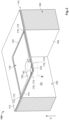
- a sensor die 100 according to an embodiment is shown in Figures 1-3 .
- the sensor die 100 includes a diaphragm 110, a plurality of piezoresistive elements 170 disposed on the diaphragm 110, and a support 160 on which the diaphragm 110 is disposed.
- the diaphragm 110 has a first side 112 and a second side 114 opposite the first side 112 in a vertical direction V.
- the first side 112 of the diaphragm 110 is exposed and faces outward from the sensor die 100.
- the second side 114 of the diaphragm 110 abuts the support 160.
- the diaphragm 110 has a first layer 116 and a second layer 120 disposed on the first layer 116 in the vertical direction V.
- the diaphragm 110 with the first layer 116 and the second layer 120 forms a first membrane 130 and a second membrane 140 positioned within the first membrane 130, as shown in Figures 1-3 .
- the first membrane 130 has a first perimeter 132 on the diaphragm 110 defining an outer extent of the first membrane 130, while the second membrane 140 has a second perimeter 142 positioned within the first membrane 130 and defining an outer extent of the second membrane 140.
- the first membrane 130 surrounds the second membrane 140 and extends between the first perimeter 132 and the second perimeter 142.
- the first membrane 130 is formed of the first layer 116 and the second layer 120 shown in Figure 3 .
- the first membrane 130 has a first thickness 133 extending between the first side 112 and the second side 114 in the vertical direction V.
- the first layer 116 has a diaphragm cavity 118 extending into the first layer 116.
- the diaphragm cavity 118 has a diaphragm perimeter 119 that is aligned with the second perimeter 142 of the second membrane 140.
- the second membrane 140 is formed by a portion of the second layer 120 extending over the diaphragm cavity 118, as shown in Figure 3 ; the position of the diaphragm cavity 118 in the first layer 116 defines the position and extent of the second membrane 140.
- the second membrane 140 is formed of only the second layer 120 in the shown embodiment.
- the second membrane 140 has a second thickness 143 smaller than the first thickness 133 of the first membrane 130 in the vertical direction V.
- the diaphragm cavity 118 between the first layer 116 and the second layer 120 is a void that has a vacuum pressure. In other embodiments, the diaphragm cavity 118 may be a void having any other predetermined pressure.
- the diaphragm 110 has a recess 134 or a plurality of recesses 134 extending into the first side 112 of the diaphragm 110.
- the recesses 134 extend into the second layer 120 of the diaphragm 110 in the vertical direction V and decrease the first thickness 133 of the first membrane 130 at the position of the recesses 134.
- the recesses 134 in the shown embodiment are positioned in the first membrane 130, within the first perimeter 132, and are separated from second perimeter 142 of the second membrane 140 by a portion of the second layer 120 that does not have the recesses 134.
- the size and extent of the recesses 134 shown in Figures 1 and 2 is merely exemplary; in other embodiments, the recesses 134 may have a different area along the first side 112.
- the first membrane 130 does not have the recesses 134 and is formed of the first layer 116 and the second layer 120 throughout the area between the first perimeter 132 and the second perimeter 142.
- the first layer 116 includes a silicon portion 150 formed of a silicon material and an oxide portion 152, formed of an oxide such as silicon dioxide, disposed on the silicon portion 150.
- the diaphragm cavity 118 in this embodiment is created in the oxide portion 152, as described in greater detail below.
- the first layer 116 is entirely formed of the silicon material without the oxide portion 152 and the diaphragm cavity 118 is formed in the silicon material of the first layer 116.
- the second layer 120 is formed of the silicon material.
- the support 160 has a support cavity 162 positioned approximately centrally in the support 160 and extending through the support 160 in the vertical direction V.
- the support cavity 162 is positioned under the first membrane 130 and the second membrane 140 of the diaphragm 110 in the vertical direction V, with the second side 114 of the diaphragm 110 facing the support cavity 162.
- a support cavity perimeter 164 of the support cavity 162 is aligned with the first perimeter 132 of the first membrane 130 in the vertical direction V.
- the support 160 in an embodiment, is formed of the same silicon material as the first layer 116 and the second layer 120 of the diaphragm 110.
- the piezoresistive elements 170 include a first set 172 of piezoresistive elements 170 disposed on the first membrane 130 and a second set 174 of piezoresistive elements 170 disposed on the second membrane 140.
- the piezoresistive elements 170 are an elemental material that is patterned over or embedded into the silicon material of the second layer 120 of the diaphragm 110; the piezoresistive elements 170 can be positioned on a surface of or within the second layer 120.
- the elemental material is a positive dopant, such as p-type boron, but could be any type of material used to create a piezoresistor in a silicon material.
- the first set 172 of piezoresistive elements 170 are positioned along the first perimeter 132 of the first membrane 130 and are aligned with the support cavity perimeter 164 of the support cavity 162 in the vertical direction V.
- the second set 174 of piezoresistive elements 170 are positioned along the second perimeter 142 of the second membrane 140 and are aligned with the diaphragm perimeter 119 of the diaphragm cavity 118 in the vertical direction V.
- the first set 172 of piezoresistive elements 170 includes four piezoresistive elements distributed around the first perimeter 132 and forming a first Wheatstone bridge on the first membrane 130.
- the second set 174 of piezoresistive elements 170 includes four piezoresistive elements distributed around the second perimeter 142 and forming a second Wheatstone bridge on the second membrane 140.
- the first set 172 and the second set 174 of piezoresistive elements 170 can include three or less or more than four piezoresistive elements 170.
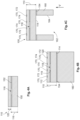
- the diaphragm 110 has the first layer 116 formed of the silicon portion 150 and the oxide portion 152 disposed on the silicon portion 150.
- the oxide portion 152 is etched to create the diaphragm cavity 118 in the first layer 116 and the second layer 120 is attached on the first layer 116, enclosing the diaphragm cavity 118.
- the first layer 116 is entirely formed of the silicon portion 150, which is etched to create the diaphragm cavity 118.
- the support 160 is bonded to the second side 114 of the diaphragm 110 by a second oxide portion 154.
- the piezoresistive elements 170 are implanted into the second layer 120 of the diaphragm 110; the second set 174 of piezoresistive elements 170 are aligned with the diaphragm perimeter 119 of the diaphragm cavity 118 in the vertical direction V.
- the piezoresistive elements 170 can be disposed on and/or within the first side 112 of the diaphragm 110.
- the support cavity 162 is then etched into the support 160 from a backside of the support 160.
- the etching extends to the second side 114 of the diaphragm 110 and, in the shown embodiment, removes part of the second oxide portion 154.
- the etching forms the support cavity perimeter 164 of the support cavity 162 aligned with the first set 172 of the piezoresistive elements 170 in the vertical direction V.
- a sensor assembly 10 according to an embodiment is shown in Figure 5 .
- the sensor assembly 10 includes the sensor die 100 described according to the above embodiments, a controller 200, and a plurality of connections 300 electrically connecting the piezoresistive elements 170 of the sensor die 100 to the controller 200.
- the controller 200 includes a processor 210 and a memory 220 connected to the processor 210.
- the memory 220 is formed of a non-transitory computer readable medium and has a plurality of algorithms stored thereon; these algorithms, when executed by the processor 210, perform the functions of the controller 200 described in detail herein.
- One of the algorithms stored on the memory 220 is a compensation algorithm 222, which will be described in greater detail below with reference to Figure 6 .
- the connections 300 in the embodiment shown in Figure 5 are each electrical lines or electrically conductive elements capable of transmitting an electrical signal.
- the connections 300 include a supply 310, a ground 320, a first pair of outputs 330, and a second pair of outputs 340.
- the supply 310 is a single connection shared among the first set 172 and the second set 174 of the piezoresistive elements 170 that supplies a voltage to the piezoresistive elements 170.
- the ground 320 in the shown embodiment, is also a single connection shared among the first set 172 and the second set 174 of the piezoresistive elements 170.
- the first outputs 330 connect the first set 172 of piezoresistive elements 170 to the controller 200 and the second outputs 340 connect the second set 174 of piezoresistive elements 170 to the controller 200.
- the sensor die 100 is used to measure pressure, from a physical element or from a fluid, in the environment in which it is placed.
- a first pressure P1 shown in Figures 1 and 2 , acts on the first side 112 of the diaphragm 110.
- the location of the first pressure P1 shown in Figures 1 and 2 is merely exemplary; the first pressure P1 acts across both the first membrane 130 and the second membrane 140 in the vertical direction V.
- the first membrane 130 and the second membrane 140 formed by the layers 116, 120 of the diaphragm 110 are deflectable and deflect in proportion with a magnitude of the first pressure P1 toward the support cavity 162 in the vertical direction V.
- the support cavity 162 has a second pressure P2 acting on the second side 114 of the diaphragm 110.
- the location of the second pressure P2 in Figure 2 is merely exemplary; the second pressure P2 acts across the second side 114 of the diaphragm 110 in the vertical direction V opposite to the first pressure P1.
- the second pressure P2 on the second side 114 of the first membrane 130 acts counter to the first pressure P1 on the first side 112 of the first membrane 130, the first membrane 130 is deflectable in proportion with a differential pressure between the first pressure P1 on the first side 112 and the second pressure P2 on the second side 114.
- a resistance of the first set 172 of piezoresistive elements 170 changes in proportion with the deflection of the first membrane 130.
- a first signal output along the first pair of outputs 330 to the controller 200 shown in Figure 5 also changes; the first signal transmitted to the controller 200 through the first set 172 of piezoresistive elements 170 represents the deflection of the first membrane 130 and the differential pressure between the first pressure P1 and the second pressure P2.
- the second membrane 140 is deflectable simultaneously with the first membrane 130 under the first pressure P1.
- the vacuum or known pressure acts counter to the first pressure P1 on the second membrane 140.
- the second membrane 140 is thereby deflectable into the diaphragm cavity 118 in proportion with an absolute measure of the first pressure P1 on the first side 112 of the diaphragm 110.
- the second membrane 140 positioned within the first membrane 130 deflects simultaneously with the first membrane 130 but in proportion to a different measure of pressure than the first membrane 130.
- a resistance of the second set 174 of piezoresistive elements 170 changes in proportion with the deflection of the second membrane 140.
- a second signal output along the second pair of outputs 340 to the controller 200 shown in Figure 5 also changes; the second signal transmitted to the controller 200 through the second set 174 of piezoresistive elements 170 represents the deflection of the second membrane 140 and the absolute measure of the first pressure P1.
- the recesses 134 increase the sensitivity of the deflection of the first membrane 130 to the differential pressure without affecting the sensitivity of the deflection of the second membrane 140 to the absolute pressure.
- the stress and deflection caused by the differential pressure on the first membrane 130 may affect the simultaneous deflection of the second membrane 140 and the measurement of the absolute pressure from the second set 174 of piezoresistive elements 170.
- the controller 200 can also process the differential and absolute pressure measurements received through the piezoresistive elements 170 to compensate for the deflection of the first membrane 130 that transmits stress to the second set 174 of piezoresistive elements 170.
- Figure 6 is a graphical representation of the compensation algorithm 222 stored on the memory 220 and executable by the processor 210.
- the compensation algorithm 222 stores a plurality of output errors 224 in relation to a measured differential pressure 226 from the first set 172 of piezoresistive elements 170 and a measured absolute pressure 228 from the second set 174 of piezoresistive elements 170.
- the output error 224 to be applied to the measured absolute pressure 228 to correct the absolute pressure 228 can be determined from the relationship in the compensation algorithm 222.
- a measured differential pressure 226 of 4.14 kN/m 2 (0.6 psi) and a measured absolute pressure 228 of 344.74 kN/m 2 (50 psi) gives an output error 224 of -0.5%.
- the relationship between the measured differential pressures 226, the measured absolute pressures 228, and the output errors 224 is determined by calibration in controlled conditions, applying 0 kN/m 2 (0 psi) and 344.74 kN/m 2 (50 psi) for the absolute pressure in various combinations with applied 0, -6.894 and 6.894 kN/m 2 (0, -1, and 1 psi) for the differential pressure and measuring the outputs.
- a base error is determined in the absolute pressure with the differential pressure set to 0 kN/m 2 (0 psi).
- a slope is then determined for the error over differential pressures while holding the absolute pressure at 0 and 344.74 kN/m 2 (0 and 50 psi). This base and slope can then be used to determine the output errors 224 at a range of measured differential pressures 226 and measured absolute pressures 228.
- the processor 210 of the controller 200 can then execute the compensation algorithm 222 to calculate an actual absolute pressure based on the measured absolute pressure 228 multiplied by the output error 224.
- the actual absolute pressure would be 346.46 kN/m 2 (50.25 psi), which is 1.72 kN/m 2 (0.25 psi), or 0.5%, more than the measured absolute pressure 228 of 344.74 kN/m 2 (50 psi); the negative output error in the graph of Figure 6 indicates that the measured absolute pressure 228 is low and needs to be compensated higher.
- the actual absolute pressure corrects for the error in the measured absolute pressure 228 caused by the deflection of the first membrane 130.
- the controller 200 receiving the differential pressure P1-P2 measurement and the absolute pressure P1 measurement from piezoresistive elements 170 of the sensor die 100 can transmit the measurements, compensated or uncompensated, externally for further use and processing.
- the sensor die 100, and the sensor assembly 10 including the sensor die 100, according to the invention has the first membrane 130 measuring the differential pressure and the second membrane 140 simultaneously measuring the absolute pressure formed within the same diaphragm 110. Incorporating both a differential pressure measurement and an absolute pressure measurement within membranes 130, 140 of the same diaphragm 110 decreases the component count and overall size of the sensor die 100, allowing for lower manufacturing costs and improved flexibility in small applications. Further, compensating for potential errors in the absolute measurement caused by deflection of the first membrane 130 maintains a high accuracy of both the absolute and differential pressure measurements made with the sensor die 100.
Landscapes
- Physics & Mathematics (AREA)
- General Physics & Mathematics (AREA)
- Chemical & Material Sciences (AREA)
- Analytical Chemistry (AREA)
- Measuring Fluid Pressure (AREA)
Abstract
Description
- The present invention relates to a sensor die and, more particularly, to a diaphragm of a sensor die.
- A pressure sensor commonly includes a sensor diaphragm and piezoresistors disposed on the sensor diaphragm. An applied force or pressure deflects the sensor diaphragm, which changes the resistance of the piezoresistors on the diaphragm, correspondingly changing a measured output of the pressure sensor that reflects the force or pressure.
- Certain applications, such as a mass flow controller, require measurement of both an absolute and a differential pressure. Existing pressure sensors, however, use separate components to measure the absolute and differential pressure, respectively; for example, one sensor diaphragm with piezoresistors measures the absolute pressure and another separate sensor diaphragm with different piezoresistors measures the differential pressure. Using multiple diaphragms to measure these pressures increases the number of components required for the pressure sensor, increasing manufacturing costs. Further, using multiple diaphragms increases the size or footprint of the pressure sensor, which can restrict the use of the pressure sensor in certain applications.
- A sensor die includes a diaphragm having a first membrane and a second membrane positioned within the first membrane. The first membrane is deflectable in proportion with a differential pressure between a first side of the diaphragm and a second side of the diaphragm opposite the first side. The second membrane is deflectable simultaneously with the first membrane in proportion with an absolute pressure on the first side of the diaphragm.
- The invention will now be described by way of example with reference to the accompanying Figures, of which:
-
Figure 1 is a perspective view of a sensor die according to an embodiment; -
Figure 2 is a sectional perspective view of the sensor die, taken along line A-A ofFigure 1 ; -
Figure 3 is a detail perspective view of a portion B ofFigure 2 ; -
Figure 4A is a schematic sectional diagram of a step of a process of manufacturing the sensor die; -
Figure 4B is a schematic sectional diagram of another step of the process of manufacturing the sensor die; -
Figure 4C is a schematic sectional diagram of another step of the process of manufacturing the sensor die; -
Figure 5 is a schematic block diagram of a sensor assembly according to an embodiment; and -
Figure 6 is a graph depicting a relationship of a compensation algorithm according to an embodiment. - Exemplary embodiments of the present disclosure will be described hereinafter in detail with reference to the attached drawings, wherein like reference numerals refer to like elements. The present disclosure may, however, be embodied in many different forms and should not be construed as being limited to the embodiments set forth herein; rather, these embodiments are provided so that the present disclosure will convey the concept of the disclosure to those skilled in the art. In addition, in the following detailed description, for purposes of explanation, numerous specific details are set forth to provide a thorough understanding of the disclosed embodiments. However, it is apparent that one or more embodiments may also be implemented without these specific details.
- Throughout the drawings, only one of a plurality of identical elements may be labeled in a figure for clarity of the drawings, but the detailed description of the element herein applies equally to each of the identically appearing elements in the figure. Throughout the specification, directional descriptors are used such as "vertical direction". These descriptors are merely for clarity of the description and for differentiation of the various directions. These directional descriptors do not imply or require any particular orientation of the disclosed elements.
- A sensor die 100 according to an embodiment is shown in
Figures 1-3 . The sensor die 100 includes adiaphragm 110, a plurality of piezoresistive elements 170 disposed on thediaphragm 110, and asupport 160 on which thediaphragm 110 is disposed. - The
diaphragm 110, as shown inFigures 1-3 , has afirst side 112 and asecond side 114 opposite thefirst side 112 in a vertical direction V. Thefirst side 112 of thediaphragm 110 is exposed and faces outward from thesensor die 100. Thesecond side 114 of thediaphragm 110 abuts thesupport 160. Between thefirst side 112 and thesecond side 114, as shown in detail inFigure 3 , thediaphragm 110 has afirst layer 116 and asecond layer 120 disposed on thefirst layer 116 in the vertical direction V. - The
diaphragm 110 with thefirst layer 116 and thesecond layer 120 forms afirst membrane 130 and asecond membrane 140 positioned within thefirst membrane 130, as shown inFigures 1-3 . Thefirst membrane 130 has afirst perimeter 132 on thediaphragm 110 defining an outer extent of thefirst membrane 130, while thesecond membrane 140 has asecond perimeter 142 positioned within thefirst membrane 130 and defining an outer extent of thesecond membrane 140. Thefirst membrane 130 surrounds thesecond membrane 140 and extends between thefirst perimeter 132 and thesecond perimeter 142. - The
first membrane 130 is formed of thefirst layer 116 and thesecond layer 120 shown inFigure 3 . Thefirst membrane 130 has afirst thickness 133 extending between thefirst side 112 and thesecond side 114 in the vertical direction V. As shown inFigure 3 , thefirst layer 116 has adiaphragm cavity 118 extending into thefirst layer 116. Thediaphragm cavity 118 has adiaphragm perimeter 119 that is aligned with thesecond perimeter 142 of thesecond membrane 140. - The
second membrane 140 is formed by a portion of thesecond layer 120 extending over thediaphragm cavity 118, as shown inFigure 3 ; the position of thediaphragm cavity 118 in thefirst layer 116 defines the position and extent of thesecond membrane 140. Thesecond membrane 140 is formed of only thesecond layer 120 in the shown embodiment. Thesecond membrane 140 has asecond thickness 143 smaller than thefirst thickness 133 of thefirst membrane 130 in the vertical direction V. - In an embodiment, the
diaphragm cavity 118 between thefirst layer 116 and thesecond layer 120 is a void that has a vacuum pressure. In other embodiments, thediaphragm cavity 118 may be a void having any other predetermined pressure. - In the embodiment shown in
Figures 1 and2 , thediaphragm 110 has arecess 134 or a plurality ofrecesses 134 extending into thefirst side 112 of thediaphragm 110. Therecesses 134 extend into thesecond layer 120 of thediaphragm 110 in the vertical direction V and decrease thefirst thickness 133 of thefirst membrane 130 at the position of therecesses 134. Therecesses 134 in the shown embodiment are positioned in thefirst membrane 130, within thefirst perimeter 132, and are separated fromsecond perimeter 142 of thesecond membrane 140 by a portion of thesecond layer 120 that does not have therecesses 134. The size and extent of therecesses 134 shown inFigures 1 and2 is merely exemplary; in other embodiments, therecesses 134 may have a different area along thefirst side 112. In another embodiment, thefirst membrane 130 does not have therecesses 134 and is formed of thefirst layer 116 and thesecond layer 120 throughout the area between thefirst perimeter 132 and thesecond perimeter 142. - In the embodiment shown in
Figure 3 , thefirst layer 116 includes asilicon portion 150 formed of a silicon material and anoxide portion 152, formed of an oxide such as silicon dioxide, disposed on thesilicon portion 150. Thediaphragm cavity 118 in this embodiment is created in theoxide portion 152, as described in greater detail below. In another embodiment, thefirst layer 116 is entirely formed of the silicon material without theoxide portion 152 and thediaphragm cavity 118 is formed in the silicon material of thefirst layer 116. In various embodiments, thesecond layer 120 is formed of the silicon material. - The
support 160, as shown inFigure 2 , has asupport cavity 162 positioned approximately centrally in thesupport 160 and extending through thesupport 160 in the vertical direction V. Thesupport cavity 162 is positioned under thefirst membrane 130 and thesecond membrane 140 of thediaphragm 110 in the vertical direction V, with thesecond side 114 of thediaphragm 110 facing thesupport cavity 162. Asupport cavity perimeter 164 of thesupport cavity 162 is aligned with thefirst perimeter 132 of thefirst membrane 130 in the vertical direction V. Thesupport 160, in an embodiment, is formed of the same silicon material as thefirst layer 116 and thesecond layer 120 of thediaphragm 110. - The piezoresistive elements 170, as shown in
Figures 1-3 , include a first set 172 of piezoresistive elements 170 disposed on thefirst membrane 130 and a second set 174 of piezoresistive elements 170 disposed on thesecond membrane 140. The piezoresistive elements 170 are an elemental material that is patterned over or embedded into the silicon material of thesecond layer 120 of thediaphragm 110; the piezoresistive elements 170 can be positioned on a surface of or within thesecond layer 120. In an embodiment, the elemental material is a positive dopant, such as p-type boron, but could be any type of material used to create a piezoresistor in a silicon material. - As shown in
Figures 1-3 , the first set 172 of piezoresistive elements 170 are positioned along thefirst perimeter 132 of thefirst membrane 130 and are aligned with thesupport cavity perimeter 164 of thesupport cavity 162 in the vertical direction V. The second set 174 of piezoresistive elements 170 are positioned along thesecond perimeter 142 of thesecond membrane 140 and are aligned with thediaphragm perimeter 119 of thediaphragm cavity 118 in the vertical direction V. - In the shown embodiment, the first set 172 of piezoresistive elements 170 includes four piezoresistive elements distributed around the
first perimeter 132 and forming a first Wheatstone bridge on thefirst membrane 130. The second set 174 of piezoresistive elements 170 includes four piezoresistive elements distributed around thesecond perimeter 142 and forming a second Wheatstone bridge on thesecond membrane 140. In other embodiments, the first set 172 and the second set 174 of piezoresistive elements 170 can include three or less or more than four piezoresistive elements 170. - A process of manufacturing the sensor die 100 will now be described in greater detail with reference to
Figures 4A-4C . - As shown in
Figure 4A , thediaphragm 110 has thefirst layer 116 formed of thesilicon portion 150 and theoxide portion 152 disposed on thesilicon portion 150. Theoxide portion 152 is etched to create thediaphragm cavity 118 in thefirst layer 116 and thesecond layer 120 is attached on thefirst layer 116, enclosing thediaphragm cavity 118. In another embodiment, thefirst layer 116 is entirely formed of thesilicon portion 150, which is etched to create thediaphragm cavity 118. - As shown in
Figure 4B , thesupport 160 is bonded to thesecond side 114 of thediaphragm 110 by asecond oxide portion 154. The piezoresistive elements 170 are implanted into thesecond layer 120 of thediaphragm 110; the second set 174 of piezoresistive elements 170 are aligned with thediaphragm perimeter 119 of thediaphragm cavity 118 in the vertical direction V. The piezoresistive elements 170 can be disposed on and/or within thefirst side 112 of thediaphragm 110. - In a step shown in
Figure 4C , thesupport cavity 162 is then etched into thesupport 160 from a backside of thesupport 160. The etching extends to thesecond side 114 of thediaphragm 110 and, in the shown embodiment, removes part of thesecond oxide portion 154. The etching forms thesupport cavity perimeter 164 of thesupport cavity 162 aligned with the first set 172 of the piezoresistive elements 170 in the vertical direction V. - A
sensor assembly 10 according to an embodiment is shown inFigure 5 . Thesensor assembly 10 includes the sensor die 100 described according to the above embodiments, acontroller 200, and a plurality ofconnections 300 electrically connecting the piezoresistive elements 170 of the sensor die 100 to thecontroller 200. - The
controller 200, as shown inFigure 5 , includes aprocessor 210 and amemory 220 connected to theprocessor 210. Thememory 220 is formed of a non-transitory computer readable medium and has a plurality of algorithms stored thereon; these algorithms, when executed by theprocessor 210, perform the functions of thecontroller 200 described in detail herein. One of the algorithms stored on thememory 220 is acompensation algorithm 222, which will be described in greater detail below with reference toFigure 6 . - The
connections 300 in the embodiment shown inFigure 5 are each electrical lines or electrically conductive elements capable of transmitting an electrical signal. As shown inFigure 5 , theconnections 300 include asupply 310, aground 320, a first pair ofoutputs 330, and a second pair ofoutputs 340. Thesupply 310 is a single connection shared among the first set 172 and the second set 174 of the piezoresistive elements 170 that supplies a voltage to the piezoresistive elements 170. Theground 320, in the shown embodiment, is also a single connection shared among the first set 172 and the second set 174 of the piezoresistive elements 170. Thefirst outputs 330 connect the first set 172 of piezoresistive elements 170 to thecontroller 200 and thesecond outputs 340 connect the second set 174 of piezoresistive elements 170 to thecontroller 200. - The function of the
sensor assembly 10 and the sensor die 100 will now be described in greater detail, primarily with reference toFigures 1 and5 . - The sensor die 100 is used to measure pressure, from a physical element or from a fluid, in the environment in which it is placed. A first pressure P1, shown in
Figures 1 and2 , acts on thefirst side 112 of thediaphragm 110. The location of the first pressure P1 shown inFigures 1 and2 is merely exemplary; the first pressure P1 acts across both thefirst membrane 130 and thesecond membrane 140 in the vertical direction V. Thefirst membrane 130 and thesecond membrane 140 formed by thelayers diaphragm 110 are deflectable and deflect in proportion with a magnitude of the first pressure P1 toward thesupport cavity 162 in the vertical direction V. - As shown in
Figure 2 , thesupport cavity 162 has a second pressure P2 acting on thesecond side 114 of thediaphragm 110. The location of the second pressure P2 inFigure 2 is merely exemplary; the second pressure P2 acts across thesecond side 114 of thediaphragm 110 in the vertical direction V opposite to the first pressure P1. As the second pressure P2 on thesecond side 114 of thefirst membrane 130 acts counter to the first pressure P1 on thefirst side 112 of thefirst membrane 130, thefirst membrane 130 is deflectable in proportion with a differential pressure between the first pressure P1 on thefirst side 112 and the second pressure P2 on thesecond side 114. - A resistance of the first set 172 of piezoresistive elements 170 changes in proportion with the deflection of the
first membrane 130. As the resistance of the first set 172 changes, a first signal output along the first pair ofoutputs 330 to thecontroller 200 shown inFigure 5 also changes; the first signal transmitted to thecontroller 200 through the first set 172 of piezoresistive elements 170 represents the deflection of thefirst membrane 130 and the differential pressure between the first pressure P1 and the second pressure P2. - The
second membrane 140 is deflectable simultaneously with thefirst membrane 130 under the first pressure P1. As thediaphragm cavity 118 has a vacuum pressure or a known pressure, the vacuum or known pressure acts counter to the first pressure P1 on thesecond membrane 140. Thesecond membrane 140 is thereby deflectable into thediaphragm cavity 118 in proportion with an absolute measure of the first pressure P1 on thefirst side 112 of thediaphragm 110. Thesecond membrane 140 positioned within thefirst membrane 130 deflects simultaneously with thefirst membrane 130 but in proportion to a different measure of pressure than thefirst membrane 130. - A resistance of the second set 174 of piezoresistive elements 170 changes in proportion with the deflection of the
second membrane 140. As the resistance of the second set 174 changes, a second signal output along the second pair ofoutputs 340 to thecontroller 200 shown inFigure 5 also changes; the second signal transmitted to thecontroller 200 through the second set 174 of piezoresistive elements 170 represents the deflection of thesecond membrane 140 and the absolute measure of the first pressure P1. - In the embodiment of the
first membrane 130 having therecesses 134 shown inFigures 1 and2 , therecesses 134 increase the sensitivity of the deflection of thefirst membrane 130 to the differential pressure without affecting the sensitivity of the deflection of thesecond membrane 140 to the absolute pressure. - In some applications, the stress and deflection caused by the differential pressure on the
first membrane 130 may affect the simultaneous deflection of thesecond membrane 140 and the measurement of the absolute pressure from the second set 174 of piezoresistive elements 170. In an embodiment, thecontroller 200 can also process the differential and absolute pressure measurements received through the piezoresistive elements 170 to compensate for the deflection of thefirst membrane 130 that transmits stress to the second set 174 of piezoresistive elements 170. -
Figure 6 is a graphical representation of thecompensation algorithm 222 stored on thememory 220 and executable by theprocessor 210. Thecompensation algorithm 222 stores a plurality ofoutput errors 224 in relation to a measureddifferential pressure 226 from the first set 172 of piezoresistive elements 170 and a measuredabsolute pressure 228 from the second set 174 of piezoresistive elements 170. For a givendifferential pressure 226 and a givenabsolute pressure 228, theoutput error 224 to be applied to the measuredabsolute pressure 228 to correct theabsolute pressure 228 can be determined from the relationship in thecompensation algorithm 222. For example, a measureddifferential pressure 226 of 4.14 kN/m2 (0.6 psi) and a measuredabsolute pressure 228 of 344.74 kN/m2 (50 psi) gives anoutput error 224 of -0.5%. - The relationship between the measured
differential pressures 226, the measuredabsolute pressures 228, and theoutput errors 224 is determined by calibration in controlled conditions, applying 0 kN/m2 (0 psi) and 344.74 kN/m2 (50 psi) for the absolute pressure in various combinations with applied 0, -6.894 and 6.894 kN/m2 (0, -1, and 1 psi) for the differential pressure and measuring the outputs. A base error is determined in the absolute pressure with the differential pressure set to 0 kN/m2 (0 psi). A slope is then determined for the error over differential pressures while holding the absolute pressure at 0 and 344.74 kN/m2 (0 and 50 psi). This base and slope can then be used to determine theoutput errors 224 at a range of measureddifferential pressures 226 and measuredabsolute pressures 228. - The
processor 210 of thecontroller 200 can then execute thecompensation algorithm 222 to calculate an actual absolute pressure based on the measuredabsolute pressure 228 multiplied by theoutput error 224. In the example used above, the actual absolute pressure would be 346.46 kN/m2 (50.25 psi), which is 1.72 kN/m2 (0.25 psi), or 0.5%, more than the measuredabsolute pressure 228 of 344.74 kN/m2 (50 psi); the negative output error in the graph ofFigure 6 indicates that the measuredabsolute pressure 228 is low and needs to be compensated higher. The actual absolute pressure corrects for the error in the measuredabsolute pressure 228 caused by the deflection of thefirst membrane 130. - The
controller 200 receiving the differential pressure P1-P2 measurement and the absolute pressure P1 measurement from piezoresistive elements 170 of the sensor die 100 can transmit the measurements, compensated or uncompensated, externally for further use and processing. - The sensor die 100, and the
sensor assembly 10 including the sensor die 100, according to the invention has thefirst membrane 130 measuring the differential pressure and thesecond membrane 140 simultaneously measuring the absolute pressure formed within thesame diaphragm 110. Incorporating both a differential pressure measurement and an absolute pressure measurement withinmembranes same diaphragm 110 decreases the component count and overall size of the sensor die 100, allowing for lower manufacturing costs and improved flexibility in small applications. Further, compensating for potential errors in the absolute measurement caused by deflection of thefirst membrane 130 maintains a high accuracy of both the absolute and differential pressure measurements made with the sensor die 100.
Claims (15)
- A sensor die (100), comprising:
a diaphragm (110) having a first membrane (130) and a second membrane (140) positioned within the first membrane (130), the first membrane (130) is deflectable in proportion with a differential pressure between a first side (112) of the diaphragm (110) and a second side (114) of the diaphragm (110) opposite the first side (112), the second membrane (140) is deflectable simultaneously with the first membrane (130) in proportion with an absolute pressure on the first side (112) of the diaphragm (110). - The sensor die (100) of claim 1, wherein the diaphragm (110) includes a first layer (116) and a second layer (120) disposed on the first layer (116), the first membrane (130) is formed of the first layer (116) and the second layer (120), and the second membrane (140) is formed of the second layer (120).
- The sensor die (100) of claim 2, wherein the first layer (116) has a diaphragm cavity (118) extending into the first layer (116), the second membrane (140) is formed by a portion of the second layer (120) extending over the diaphragm cavity (118).
- The sensor die (100) of any preceding claim, wherein the first membrane (130) has a recess (134) extending into the first side (112) of the diaphragm (110), the recess (134) is separated from the second membrane (140).
- The sensor die (100) of any preceding claim, further comprising a support (160) on which the diaphragm (110) is disposed, the support (160) has a support cavity (162), the second side (114) of the diaphragm (110) faces the support cavity (162).
- The sensor die (100) of any preceding claim, further comprising a plurality of piezoresistive elements (170) including a first set (172) forming a first Wheatstone bridge positioned on the first membrane (130), and a second set (174) forming a second Wheatstone bridge positioned on the second membrane (140).
- A process of manufacturing a sensor die (100), comprising:providing a first layer (116) of a diaphragm (110);etching a diaphragm cavity (118) into the first layer (116); andattaching a second layer (120) of the diaphragm (110) on the first layer (116), a portion of the first layer (116) and the second layer (120) outside of the diaphragm cavity (118) forms a first membrane (130) and a portion of the second layer (120) extending over the diaphragm cavity (118) forms a second membrane (140) positioned within the first membrane (130), the first membrane (130) is deflectable in proportion with a differential pressure between a first side (112) of the diaphragm (110) and a second side (114) of the diaphragm (110) opposite the first side (112), the second membrane (140) is deflectable simultaneously with the first membrane (130) in proportion with an absolute pressure on the first side (112) of the diaphragm (110).
- The process of claim 7, wherein the first layer (116) includes a silicon (150) and an oxide (152) disposed on the silicon (150), the diaphragm cavity (118) is formed in the oxide (152) of the first layer (116).
- The process of any of claims 7 or 8, further comprising bonding a support (160) to the second side (114) of the diaphragm (110) and etching a support cavity (162) into the support (160), the second side (114) of the diaphragm (110) faces the support cavity (162).
- The process of any of claims 7 to 9, further comprising implanting a plurality of piezoresistive elements (170) in the second layer (120).
- The process of claims 9 and 10, wherein a first set (172) of the piezoresistive elements (170) is disposed on the first membrane (130) and aligned with a perimeter (164) of the support cavity (162), and a second set (174) of the piezoresistive elements (170) is disposed on the second membrane (140) and aligned with a perimeter (119) of the diaphragm cavity (118).
- A sensor assembly (10), comprising:
a sensor die (100) including a diaphragm (110) having a first membrane (130) and a second membrane (140) positioned within the first membrane (130), the first membrane (130) is deflectable in proportion with a differential pressure between a first side (112) of the diaphragm (110) and a second side (114) of the diaphragm (110) opposite the first side (112), the second membrane (140) is deflectable simultaneously with the first membrane (130) in proportion with an absolute pressure on the first side (112) of the diaphragm (110). - The sensor assembly (10) of claim 12, wherein the sensor die (100) includes a plurality of piezoresistive elements (170) including a first set (172) forming a first Wheatstone bridge positioned on the first membrane (130), and a second set (174) forming a second Wheatstone bridge positioned on the second membrane (140), and further comprising a plurality of connections (300) connected to the piezoresistive elements (170), the first set (172) and the second set (174) of the piezoresistive elements (170) share at least one of a supply (310) and a ground (320) of the connections (300).
- The sensor assembly (10) of claim 13, further comprising a controller (200) connected to the first set (172) of the piezoresistive elements (170) by a plurality of first outputs (330) and connected to the second set (174) of the piezoresistive elements (170) by a plurality of second outputs (340), the controller (200) receives the differential pressure measured by the first set (172) of the piezoresistive elements (170) and the absolute pressure measured by the second set (174) of the piezoresistive elements (170).
- The sensor assembly (10) of claim 14, wherein the controller (200) executes a compensation algorithm (222) based on the differential pressure to correct an error in the absolute pressure.
Applications Claiming Priority (1)
| Application Number | Priority Date | Filing Date | Title |
|---|---|---|---|
| US18/169,939 US12436049B2 (en) | 2023-02-16 | 2023-02-16 | Sensor die with a diaphragm |
Publications (1)
| Publication Number | Publication Date |
|---|---|
| EP4417951A1 true EP4417951A1 (en) | 2024-08-21 |
Family
ID=89977705
Family Applications (1)
| Application Number | Title | Priority Date | Filing Date |
|---|---|---|---|
| EP24157840.0A Withdrawn EP4417951A1 (en) | 2023-02-16 | 2024-02-15 | Sensor die with a diaphragm |
Country Status (5)
| Country | Link |
|---|---|
| US (1) | US12436049B2 (en) |
| EP (1) | EP4417951A1 (en) |
| JP (1) | JP2024117080A (en) |
| KR (1) | KR20240127907A (en) |
| CN (1) | CN118500589A (en) |
Citations (2)
| Publication number | Priority date | Publication date | Assignee | Title |
|---|---|---|---|---|
| WO2011117181A2 (en) * | 2010-03-22 | 2011-09-29 | Elmos Semiconductor Ag | Method for producing a microelectromechanical device and microelectromechanical device |
| US20150114129A1 (en) * | 2013-10-24 | 2015-04-30 | Asia Pacific Microsystems, Inc. | Diaphragm piezoresistive pressure sensor |
Family Cites Families (34)
| Publication number | Priority date | Publication date | Assignee | Title |
|---|---|---|---|---|
| US4011650A (en) | 1973-10-01 | 1977-03-15 | International Telephone And Telegraph Corporation | Cold working process |
| US4222277A (en) | 1979-08-13 | 1980-09-16 | Kulite Semiconductor Products, Inc. | Media compatible pressure transducer |
| US4322980A (en) * | 1979-11-08 | 1982-04-06 | Hitachi, Ltd. | Semiconductor pressure sensor having plural pressure sensitive diaphragms and method |
| US4790192A (en) * | 1987-09-24 | 1988-12-13 | Rosemount Inc. | Silicon side by side coplanar pressure sensors |
| SG44494A1 (en) | 1993-09-07 | 1997-12-19 | R0Semount Inc | Multivariable transmitter |
| US5415048A (en) | 1994-06-27 | 1995-05-16 | Texaco Inc. | Acoustic gas-liquid flow meter |
| US5837903A (en) | 1995-09-22 | 1998-11-17 | The Scott Fetzer Company Inc. | Device for measuring exhaust flowrate using laminar flow element |
| GB2373054B (en) | 1999-05-26 | 2003-03-26 | Cyber Instr Technology Llc | Wide range gas flow system with real time flow measurement and correction |
| US6119710A (en) | 1999-05-26 | 2000-09-19 | Cyber Instrument Technologies Llc | Method for wide range gas flow system with real time flow measurement and correction |
| US6272928B1 (en) | 2000-01-24 | 2001-08-14 | Kulite Semiconductor Products | Hermetically sealed absolute and differential pressure transducer |
| AU2001286619A1 (en) | 2000-08-22 | 2002-03-04 | Fugasity Corporation | Fluid mass flow meter with substantial measurement range |
| US6539968B1 (en) | 2000-09-20 | 2003-04-01 | Fugasity Corporation | Fluid flow controller and method of operation |
| US6672171B2 (en) | 2001-07-16 | 2004-01-06 | Mks Instruments, Inc. | Combination differential and absolute pressure transducer for load lock control |
| JP4044307B2 (en) | 2001-08-01 | 2008-02-06 | 株式会社山武 | Pressure sensor |
| US7057247B2 (en) | 2001-12-12 | 2006-06-06 | Kulite Semiconductor Products, Inc. | Combined absolute differential transducer |
| US6543293B1 (en) | 2002-01-31 | 2003-04-08 | Kulite Semiconductor Products, Inc. | Static pitot transducer |
| DE20208716U1 (en) | 2002-06-05 | 2002-08-22 | FESTO AG & Co, 73734 Esslingen | Flow measurement device |
| JP2005156307A (en) | 2003-11-25 | 2005-06-16 | Denso Corp | Pressure sensor |
| US7082842B2 (en) | 2004-06-25 | 2006-08-01 | Rivatek Incorporated | Software correction method and apparatus for a variable orifice flow meter |
| US7467555B2 (en) | 2006-07-10 | 2008-12-23 | Rosemount Inc. | Pressure transmitter with multiple reference pressure sensors |
| US7275444B1 (en) | 2006-07-13 | 2007-10-02 | Kulite Semiconductor Products, Inc. | Pressure transducer apparatus adapted to measure engine pressure parameters |
| US7946117B2 (en) | 2006-12-15 | 2011-05-24 | Caterpillar Inc. | Onboard method of determining EGR flow rate |
| US7673518B2 (en) | 2008-06-19 | 2010-03-09 | Kulite Semiconductor Products, Inc. | Compact absolute and gage pressure transducer having a mounting apparatus for accurately positioning and aligning a leadless semiconductor chip on an associated header |
| DE102008041942A1 (en) * | 2008-09-10 | 2010-03-11 | Robert Bosch Gmbh | Sensor arrangement, method for operating a sensor arrangement and method for producing a sensor arrangement |
| US7775117B2 (en) | 2008-12-11 | 2010-08-17 | Kulite Semiconductor Products, Inc. | Combined wet-wet differential and gage transducer employing a common housing |
| US9010191B2 (en) | 2011-12-22 | 2015-04-21 | Rosemount Inc. | Pressure sensor module for sub-sea applications |
| US9562796B2 (en) | 2013-09-06 | 2017-02-07 | Illinois Tool Works Inc. | Absolute and differential pressure transducer |
| US9234776B2 (en) | 2013-09-26 | 2016-01-12 | Rosemount Inc. | Multivariable process fluid transmitter for high pressure applications |
| US9316552B2 (en) | 2014-02-28 | 2016-04-19 | Measurement Specialties, Inc. | Differential pressure sensing die |
| US9638559B1 (en) | 2016-02-10 | 2017-05-02 | Sensata Technologies Inc. | System, devices and methods for measuring differential and absolute pressure utilizing two MEMS sense elements |
| DE102016124410A1 (en) * | 2016-12-14 | 2018-06-14 | Trafag Ag | Method for producing a pressure sensor element as well as pressure sensor measuring element available therewith |
| US11073846B2 (en) | 2018-01-30 | 2021-07-27 | Illinois Tool Works Inc. | Mass flow controller with absolute and differential pressure transducer |
| US10871407B2 (en) | 2019-04-25 | 2020-12-22 | Measurement Specialties, Inc. | Sensor assemblies with multirange construction |
| US20240302236A1 (en) * | 2023-03-10 | 2024-09-12 | Te Connectivity Solutions Gmbh | Sensor Package With A Sensor Die |
-
2023
- 2023-02-16 US US18/169,939 patent/US12436049B2/en active Active
-
2024
- 2024-02-07 CN CN202410173928.3A patent/CN118500589A/en active Pending
- 2024-02-13 JP JP2024019110A patent/JP2024117080A/en active Pending
- 2024-02-15 EP EP24157840.0A patent/EP4417951A1/en not_active Withdrawn
- 2024-02-16 KR KR1020240022698A patent/KR20240127907A/en active Pending
Patent Citations (2)
| Publication number | Priority date | Publication date | Assignee | Title |
|---|---|---|---|---|
| WO2011117181A2 (en) * | 2010-03-22 | 2011-09-29 | Elmos Semiconductor Ag | Method for producing a microelectromechanical device and microelectromechanical device |
| US20150114129A1 (en) * | 2013-10-24 | 2015-04-30 | Asia Pacific Microsystems, Inc. | Diaphragm piezoresistive pressure sensor |
Also Published As
| Publication number | Publication date |
|---|---|
| JP2024117080A (en) | 2024-08-28 |
| US12436049B2 (en) | 2025-10-07 |
| KR20240127907A (en) | 2024-08-23 |
| CN118500589A (en) | 2024-08-16 |
| US20240280425A1 (en) | 2024-08-22 |
Similar Documents
| Publication | Publication Date | Title |
|---|---|---|
| EP0164413B1 (en) | Pressure transducer | |
| US4986127A (en) | Multi-functional sensor | |
| US7775117B2 (en) | Combined wet-wet differential and gage transducer employing a common housing | |
| US4574640A (en) | Integrated dual-range pressure transducer | |
| US7866215B2 (en) | Redundant self compensating leadless pressure sensor | |
| US9651441B2 (en) | Pressure sensor device with high sensitivity and high accuracy | |
| US5291788A (en) | Semiconductor pressure sensor | |
| EP0753728A2 (en) | Semiconductor differential pressure measuring device | |
| EP3730912B1 (en) | Sensor assemblies with multirange construction | |
| KR20190030628A (en) | Pressure sensor with improved strain gauge | |
| US4511878A (en) | Pressure sensor with improved semiconductor diaphragm | |
| US20240302236A1 (en) | Sensor Package With A Sensor Die | |
| US12436049B2 (en) | Sensor die with a diaphragm | |
| EP4403895B1 (en) | Split-stacked full-bridge pressure sensor | |
| JP2895262B2 (en) | Composite sensor | |
| US12467802B2 (en) | Membrane of a sensor with multiple deflectable sections for different ranges of a sensed force or pressure | |
| JP2021039043A (en) | Pressure sensing element and pressure sensor | |
| JP2689744B2 (en) | Compound sensor, compound transmitter and plant system using the same | |
| US20260085988A1 (en) | High output extended-range strain gauge pressure sensor | |
| JPH10132682A (en) | Semiconductor pressure sensor, method of manufacturing the same, and composite transmitter using the same | |
| US20250076130A1 (en) | Pressure sensing element and method of manufacture thereof | |
| US20210108979A1 (en) | Sensor element | |
| KR20190037457A (en) | Pressure sensor module and manufacturing method thereof | |
| JPH04240532A (en) | Differential pressure sensor and its sensitivity adjustment method |
Legal Events
| Date | Code | Title | Description |
|---|---|---|---|
| PUAI | Public reference made under article 153(3) epc to a published international application that has entered the european phase |
Free format text: ORIGINAL CODE: 0009012 |
|
| STAA | Information on the status of an ep patent application or granted ep patent |
Free format text: STATUS: THE APPLICATION HAS BEEN PUBLISHED |
|
| AK | Designated contracting states |
Kind code of ref document: A1 Designated state(s): AL AT BE BG CH CY CZ DE DK EE ES FI FR GB GR HR HU IE IS IT LI LT LU LV MC ME MK MT NL NO PL PT RO RS SE SI SK SM TR |
|
| STAA | Information on the status of an ep patent application or granted ep patent |
Free format text: STATUS: REQUEST FOR EXAMINATION WAS MADE |
|
| 17P | Request for examination filed |
Effective date: 20250127 |
|
| STAA | Information on the status of an ep patent application or granted ep patent |
Free format text: STATUS: EXAMINATION IS IN PROGRESS |
|
| 17Q | First examination report despatched |
Effective date: 20250804 |
|
| STAA | Information on the status of an ep patent application or granted ep patent |
Free format text: STATUS: THE APPLICATION IS DEEMED TO BE WITHDRAWN |
|
| 18D | Application deemed to be withdrawn |
Effective date: 20251205 |