EP4417913A1 - Box device - Google Patents
Box device Download PDFInfo
- Publication number
- EP4417913A1 EP4417913A1 EP22885336.2A EP22885336A EP4417913A1 EP 4417913 A1 EP4417913 A1 EP 4417913A1 EP 22885336 A EP22885336 A EP 22885336A EP 4417913 A1 EP4417913 A1 EP 4417913A1
- Authority
- EP
- European Patent Office
- Prior art keywords
- sliding rail
- door body
- opening
- center
- sliding
- Prior art date
- Legal status (The legal status is an assumption and is not a legal conclusion. Google has not performed a legal analysis and makes no representation as to the accuracy of the status listed.)
- Pending
Links
Images






Classifications
-
- F—MECHANICAL ENGINEERING; LIGHTING; HEATING; WEAPONS; BLASTING
- F25—REFRIGERATION OR COOLING; COMBINED HEATING AND REFRIGERATION SYSTEMS; HEAT PUMP SYSTEMS; MANUFACTURE OR STORAGE OF ICE; LIQUEFACTION SOLIDIFICATION OF GASES
- F25D—REFRIGERATORS; COLD ROOMS; ICE-BOXES; COOLING OR FREEZING APPARATUS NOT OTHERWISE PROVIDED FOR
- F25D23/00—General constructional features
- F25D23/06—Walls
- F25D23/065—Details
-
- E—FIXED CONSTRUCTIONS
- E05—LOCKS; KEYS; WINDOW OR DOOR FITTINGS; SAFES
- E05D—HINGES OR SUSPENSION DEVICES FOR DOORS, WINDOWS OR WINGS
- E05D3/00—Hinges with pins
- E05D3/06—Hinges with pins with two or more pins
- E05D3/18—Hinges with pins with two or more pins with sliding pins or guides
-
- E—FIXED CONSTRUCTIONS
- E05—LOCKS; KEYS; WINDOW OR DOOR FITTINGS; SAFES
- E05D—HINGES OR SUSPENSION DEVICES FOR DOORS, WINDOWS OR WINGS
- E05D7/00—Hinges or pivots of special construction
- E05D7/08—Hinges or pivots of special construction for use in suspensions comprising two spigots placed at opposite edges of the wing, especially at the top and the bottom, e.g. trunnions
- E05D7/081—Hinges or pivots of special construction for use in suspensions comprising two spigots placed at opposite edges of the wing, especially at the top and the bottom, e.g. trunnions the pivot axis of the wing being situated near one edge of the wing, especially at the top and bottom, e.g. trunnions
-
- F—MECHANICAL ENGINEERING; LIGHTING; HEATING; WEAPONS; BLASTING
- F25—REFRIGERATION OR COOLING; COMBINED HEATING AND REFRIGERATION SYSTEMS; HEAT PUMP SYSTEMS; MANUFACTURE OR STORAGE OF ICE; LIQUEFACTION SOLIDIFICATION OF GASES
- F25D—REFRIGERATORS; COLD ROOMS; ICE-BOXES; COOLING OR FREEZING APPARATUS NOT OTHERWISE PROVIDED FOR
- F25D23/00—General constructional features
- F25D23/02—Doors; Covers
- F25D23/028—Details
-
- E—FIXED CONSTRUCTIONS
- E05—LOCKS; KEYS; WINDOW OR DOOR FITTINGS; SAFES
- E05Y—INDEXING SCHEME ASSOCIATED WITH SUBCLASSES E05D AND E05F, RELATING TO CONSTRUCTION ELEMENTS, ELECTRIC CONTROL, POWER SUPPLY, POWER SIGNAL OR TRANSMISSION, USER INTERFACES, MOUNTING OR COUPLING, DETAILS, ACCESSORIES, AUXILIARY OPERATIONS NOT OTHERWISE PROVIDED FOR, APPLICATION THEREOF
- E05Y2201/00—Constructional elements; Accessories therefor
- E05Y2201/60—Suspension or transmission members; Accessories therefor
- E05Y2201/622—Suspension or transmission members elements
- E05Y2201/682—Pins
-
- E—FIXED CONSTRUCTIONS
- E05—LOCKS; KEYS; WINDOW OR DOOR FITTINGS; SAFES
- E05Y—INDEXING SCHEME ASSOCIATED WITH SUBCLASSES E05D AND E05F, RELATING TO CONSTRUCTION ELEMENTS, ELECTRIC CONTROL, POWER SUPPLY, POWER SIGNAL OR TRANSMISSION, USER INTERFACES, MOUNTING OR COUPLING, DETAILS, ACCESSORIES, AUXILIARY OPERATIONS NOT OTHERWISE PROVIDED FOR, APPLICATION THEREOF
- E05Y2800/00—Details, accessories and auxiliary operations not otherwise provided for
- E05Y2800/20—Combinations of elements
- E05Y2800/21—Combinations of elements of identical elements, e.g. of identical compression springs
-
- E—FIXED CONSTRUCTIONS
- E05—LOCKS; KEYS; WINDOW OR DOOR FITTINGS; SAFES
- E05Y—INDEXING SCHEME ASSOCIATED WITH SUBCLASSES E05D AND E05F, RELATING TO CONSTRUCTION ELEMENTS, ELECTRIC CONTROL, POWER SUPPLY, POWER SIGNAL OR TRANSMISSION, USER INTERFACES, MOUNTING OR COUPLING, DETAILS, ACCESSORIES, AUXILIARY OPERATIONS NOT OTHERWISE PROVIDED FOR, APPLICATION THEREOF
- E05Y2800/00—Details, accessories and auxiliary operations not otherwise provided for
- E05Y2800/26—Form or shape
-
- E—FIXED CONSTRUCTIONS
- E05—LOCKS; KEYS; WINDOW OR DOOR FITTINGS; SAFES
- E05Y—INDEXING SCHEME ASSOCIATED WITH SUBCLASSES E05D AND E05F, RELATING TO CONSTRUCTION ELEMENTS, ELECTRIC CONTROL, POWER SUPPLY, POWER SIGNAL OR TRANSMISSION, USER INTERFACES, MOUNTING OR COUPLING, DETAILS, ACCESSORIES, AUXILIARY OPERATIONS NOT OTHERWISE PROVIDED FOR, APPLICATION THEREOF
- E05Y2800/00—Details, accessories and auxiliary operations not otherwise provided for
- E05Y2800/26—Form or shape
- E05Y2800/292—Form or shape having apertures
- E05Y2800/296—Slots
-
- E—FIXED CONSTRUCTIONS
- E05—LOCKS; KEYS; WINDOW OR DOOR FITTINGS; SAFES
- E05Y—INDEXING SCHEME ASSOCIATED WITH SUBCLASSES E05D AND E05F, RELATING TO CONSTRUCTION ELEMENTS, ELECTRIC CONTROL, POWER SUPPLY, POWER SIGNAL OR TRANSMISSION, USER INTERFACES, MOUNTING OR COUPLING, DETAILS, ACCESSORIES, AUXILIARY OPERATIONS NOT OTHERWISE PROVIDED FOR, APPLICATION THEREOF
- E05Y2900/00—Application of doors, windows, wings or fittings thereof
- E05Y2900/30—Application of doors, windows, wings or fittings thereof for domestic appliances
- E05Y2900/302—Application of doors, windows, wings or fittings thereof for domestic appliances for built-in appliances
-
- E—FIXED CONSTRUCTIONS
- E05—LOCKS; KEYS; WINDOW OR DOOR FITTINGS; SAFES
- E05Y—INDEXING SCHEME ASSOCIATED WITH SUBCLASSES E05D AND E05F, RELATING TO CONSTRUCTION ELEMENTS, ELECTRIC CONTROL, POWER SUPPLY, POWER SIGNAL OR TRANSMISSION, USER INTERFACES, MOUNTING OR COUPLING, DETAILS, ACCESSORIES, AUXILIARY OPERATIONS NOT OTHERWISE PROVIDED FOR, APPLICATION THEREOF
- E05Y2900/00—Application of doors, windows, wings or fittings thereof
- E05Y2900/30—Application of doors, windows, wings or fittings thereof for domestic appliances
- E05Y2900/31—Application of doors, windows, wings or fittings thereof for domestic appliances for refrigerators
-
- F—MECHANICAL ENGINEERING; LIGHTING; HEATING; WEAPONS; BLASTING
- F25—REFRIGERATION OR COOLING; COMBINED HEATING AND REFRIGERATION SYSTEMS; HEAT PUMP SYSTEMS; MANUFACTURE OR STORAGE OF ICE; LIQUEFACTION SOLIDIFICATION OF GASES
- F25D—REFRIGERATORS; COLD ROOMS; ICE-BOXES; COOLING OR FREEZING APPARATUS NOT OTHERWISE PROVIDED FOR
- F25D2323/00—General constructional features not provided for in other groups of this subclass
- F25D2323/02—Details of doors or covers not otherwise covered
- F25D2323/024—Door hinges
Definitions
- the present disclosure relates to the technical field of hinges, and in particular to a box device.
- a box device includes a door body and a box body.
- the door body When the door body is opened relative to the box body, the door body may exceed an outer sidewall of the box device, which may cause interference between the door body and an installation environment of the box device.
- the door body In the case of embedded installation of the box device, a part of the door body exceeding the outer sidewall of the box device may interfere with a wall embedded by the box device.
- a main technical problem to be solved by the present disclosure is to provide a box device, which may reduce the risk of interference and collision of the door body during rotating the door body.
- the box device includes a box body internally provided with an accommodating space with an opening.
- the box device further includes a door body configured to block the opening.
- the box device further includes a hinge assembly, and the hinge assembly is disposed on a pivoting side of the box body and pivotally connecting the box body to the door body.
- the hinge assembly includes a first connecting member and a second connecting member, the first connecting member is disposed on one of the box body and the door body, and the second connecting member is disposed on the other of the box body and the door body.
- the first connecting member is at least provided with a first sliding shaft and a second sliding shaft
- the second connecting member is at least provided with a first sliding rail and a second sliding rail.
- the first sliding shaft is connected to the first sliding rail and is able to move along the first sliding rail
- the second sliding shaft is connected to the second sliding rail and is able to move along the second sliding rail.
- the first sliding rail linearly extends
- the second sliding rail extends along an ellipse.
- the first sliding rail is perpendicular to a plane where the opening is located, a part of the second sliding rail away from the box body is closer to the pivoting side relative to the first sliding rail, so that the door body moves towards a target side of the box body during a process from blocking the opening by the door body to opening the door body relative to the box body.
- the opening includes two opposite sides, the pivoting side is disposed on one of the two opposite sides, and the target side is disposed on the other of the two opposite sides.
- a center of the ellipse is located on the first sliding rail.
- the first sliding shaft and the second sliding shaft are away from the opening relative to the center of the ellipse when the door body blocks the opening.
- the second sliding rail is located on a side of a connecting line between the second sliding shaft and a center of the ellipse away from the box body when the door body blocks the opening.
- the second sliding rail is located on a side of a connecting line between the second sliding shaft and a center of the ellipse facing the box body when the door body blocks the opening.
- the second sliding rail bends along a direction toward the pivoting side and a direction away from the box body when the door body blocks the opening.
- an end surface of the door body facing the hinge assembly includes an inner edge and an outer edge, the inner edge and the outer edge are disposed at intervals along a first direction and extend along a second direction, the first direction is perpendicular to the second direction, and the inner edge is close to the box body relative to the outer edge when the door body blocks the opening.
- the end surface of the door body facing the hinge assembly further includes a side edge, the inner edge is connected to the outer edge by the side edge, and the side edge extends along the first direction.
- the first direction is perpendicular to the plane where the opening is located, minimum distances from any one of the first sliding rail, the second sliding rail, and a third sliding rail to the inner edge, the outer edge, and the side edge are all greater than or equal to 6 mm.
- the first sliding rail where the first sliding shaft is located has a first tangent
- the second sliding rail where the second sliding shaft is located has a second tangent
- an included angle between the first tangent and the second tangent is greater than or equal to 10°.
- the second sliding rail intersects with a major axis of the ellipse at an inflection point.
- the second sliding rail has a target point, and the target point is located on a side of a minor axis of the ellipse facing the inflection point.
- an included angle between the major axis of the ellipse and a connecting line between the target point and the inflection point is greater than or equal to 10°.
- first sliding rail and the second sliding rail are spaced apart from each other.
- the second connecting member defines a reference circle, a center of the reference circle is located on a center line of the first sliding rail, and a center of the ellipse coincides with the center of the reference circle.
- the side edge is perpendicular to the plane where the opening is located, a radius of the reference circle is defined as R, a distance from the center of the reference circle to the side edge is defined as N, and R ⁇ N ⁇ 100 mm.
- a radius of the reference circle is defined as R
- a length of the side edge in the first direction is defined as D
- a distance from the center of the reference circle to the outer edge is defined as W
- R ⁇ W ⁇ (1/2)D is defined as R
- the side edge is perpendicular to the plane where the opening is located, a distance from the center of the reference circle to the side edge is defined as N, and 15 mm ⁇ N ⁇ 100 mm.
- a radius of the reference circle is defined as R
- a length of the side edge in the first direction is defined as D
- a distance from the center of the reference circle to the outer edge is defined as W
- R ⁇ W ⁇ D is defined as R
- the second connector defines a reference circle, a center of the reference circle is located on a center line of the first sliding rail, and a center of the ellipse coincides with the center of the reference circle.
- the end surface of the door body facing the hinge assembly includes the inner edge and the outer edge, and the inner edge and the outer edge are spaced apart from each other along the first direction and extend along the second direction.
- the first direction is perpendicular to the second direction.
- the inner edge is close to the box body relative to the outer edge.
- a length of the door body in the first direction is defined as H, and 35mm ⁇ H ⁇ 100mm.
- a length of the door body in the second direction is defined as L, and 300mm ⁇ L ⁇ 700mm.
- a minimum distance from the reference circle to the outer edge is defined as M, and 0 mm ⁇ M ⁇ 15 mm.
- the hinge assembly of the box device of the present disclosure is provided with the first sliding rail and the second sliding rail.
- the first sliding rail linearly extends, and the second sliding rail extends along the ellipse.
- the first sliding rail is perpendicular to the plane where the opening is located, the part of the second sliding rail away from the box body is closer to the pivoting side relative to the first sliding rail, so that the door body moves towards the target side of the box body during the process from blocking the opening by the door body to opening the door body relative to the box body. Therefore, the degree of the door body exceeding the outer sidewall of the box body is reduced, which may reduce the risk of interference or collision between the door body and an external structure during rotating the door body.
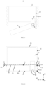
- FIG. 1 is a structural schematic view of a refrigeration device in a related art.
- a hinge structure is configured for opening and closing a door body of a refrigeration device such as a refrigerator, and usually adopts a single hinge shaft design.
- a box body 11 of a refrigerator 10 is provided with a hinge fixing plate 12, and the hinge fixing plate 12 is provided with a hinge shaft 13.
- a door body 14 of the refrigerator 10 defines a shaft hole (not shown in drawing). The hinge shaft 13 is inserted into the shaft hole, and the hinge shaft 13 may rotate in the shaft hole, so that the door body 14 may rotate relative to the box body 11, thereby achieving the opening and closing of the door body 14.
- the refrigerator 10 is embedded in a cabinet 15.
- the door body 14 exceeds an outer sidewall 111 of the box body 11 during rotating the door body 14 relative to the box body 11.
- an external structure such as the cabinet 15
- the embodiments of the present disclosure provide a box device, which may reduce the extent to which the door body exceeds the outer sidewall of the box body during rotating the door body, and may be described in detail below.
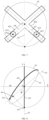
- FIG. 2 is a structural schematic view of a box device in some embodiments of the present disclosure.
- the box device may be the refrigeration device, such as, the refrigerator or a freezer.
- the box device may also be other devices that include the box body 20 and the door body 30, and the door body 30 may be rotated relative to the box body 20.
- the box device being the refrigerator is taken as an example for illustration, which is only for the purpose of discussion, and does not limit the specific form or structure of the box device.
- the box device includes the box body 20.
- the box body 20 is a storage medium of the box device, and a user stores objects to be refrigerated or frozen in the box body 20.
- an accommodating space 21 is defined in the box body 20, the accommodating space 21 has an opening 22, and the objects to be refrigerated or frozen are stored in the accommodating space 21.
- the box device further includes the door body 30 configured for sealing the opening 22 of the accommodation space 21.
- the door body 30 blocks the opening 22, that is, the door body 30 is in a closed state, and a relatively closed space is formed inside the box body 20 configured for storing the objects.
- the door body 30 is rotatably connected to a pivoting side 23 of the box body 20, that is, the door body 30 may rotate relative to the box body 20.
- the box body 20 also includes a target side 24, and the pivoting side 23 and the target side 24 are respectively disposed on two opposite sides of the opening 22.
- the box device further includes a hinge assembly 40.
- the hinge assembly 40 is disposed on the pivoting side 23 of the box body 20, and the hinge assembly 40 is pivotally connected to the box body 20 and the door body 30, so as to achieve a rotational connection between the box body 20 and the door body 30.
- the hinge assembly 40 includes a first connecting member 41 and a second connecting member 42.
- the first connecting member 41 is disposed on one of the box body 20 and the door body 30, and the second connecting member 42 is disposed on the other of the box body 20 and the door body 30.
- the first connecting member 41 is provided with a sliding shaft
- the second connecting member 42 is provided with a sliding rail.
- the sliding shaft is connected to the sliding rail, and the sliding shaft may move along the sliding rail. During rotating the door body 30 relative to the box body 20, the sliding shaft moves along the sliding rail.
- the first connecting member 41 and the second connecting member 42 may be parts of the box body 20 and the door body 30, that is, the first connecting member 41 and the second connecting member 42 may be integrated with the box body 20 and the door body 30.
- the first connecting member 41 when the first connecting member 41 is disposed on the box body 20 and the second connecting member 42 is disposed on the door body 30, the first connecting member 41 may be integrated with the box body 20, and the second connecting member 42 may be integrated with the door body 30.
- the sliding rail is in a form of a groove, a surface of the door body 30 is recessed to directly form the sliding rail, and the sliding shaft is embedded in the sliding rail. In this case, the door body 30 on the position of the sliding rail may be understood as the second connecting member 42.
- an end surface of the door body 30 facing the hinge assembly 40 includes an inner edge 31, an outer edge 32, and a side edge 33.
- the inner edge 31 and the outer edge 32 are disposed at intervals along a first direction Z1, and both extend along a second direction Z2.
- the side edge 33 is located on the pivoting side 23.
- the inner edge 31 is connected to the outer edge 32 by the side edge 33, and the side edge 33 extends along the first direction Z1.
- the side edge 33 is perpendicular to a plane 221 where the opening 22 is located.
- the door body 30 includes a first inner side edge 34 and an outer side edge 35 on the pivoting side 23.
- the first inner side edge 34 and the outer side edge 35 are disposed at intervals along the first direction Z1, and both extend along a third direction Z3.
- the first inner side edge 34 is closer to the box body 20 than the outer side edge 35.
- the first inner side edge 34 is connected to an intersection point of the inner edge 31 and the side edge 33.
- the outer side edge 35 is connected to an intersection point of the outer edge 32 and the side edge 33.
- the door body 30 further includes a second inner side edge 36 away from the pivoting side 23.
- the second inner side edge 36 extends along the third direction Z3.
- a plane where both the first inner side edge 34 and the second inner side edge 36 are located is parallel to the plane 221 where the opening 22 is located. The user usually grasps the side of the door body 30 away from the pivoting side 23 to open the door body 30.
- any two of the first direction Z1, the second direction Z2, and the third direction Z3 are perpendicular to each other.
- both the first direction Z1 and the second direction Z2 are horizontal, and the third direction Z3 is vertical.
- the pivoting side 23 and the target side 24 are disposed opposite to each other along the second direction Z2.
- the third direction Z3 is perpendicular to a drawing paper, therefore the third direction Z3 appears as a dot in FIG. 2 .
- each of the first inner side edge 34, the outer side edge 35, and the second inner side edge 36 appears as a dot in FIG. 2 .
- the box device further includes a door seal 50 disposed on the door body 30.
- the door body 30 blocks the opening 22 of the accommodating space 21 through the door seal 50, so that the accommodating space 21 may have a good sealing effect when the door body 30 blocks the opening 22.
- the door seal 50 includes a third inner side edge 51 on the pivoting side 23, the third inner side edge 51 extends along the third direction Z3, and the third inner side edge 51 is spaced apart from the door body 30. Similarly, the third inner side edge 51 appears as a dot in FIG. 2 .
- the box device in the embodiments of the present disclosure may adopt the design of single door, double door, or even more doors 30.
- the box device is provided with an independent accommodating space 21 corresponding to each door body 30. That is, the door body 30 corresponds to the accommodating space 21 one by one, and the door body 30 is configured to seal the corresponding accommodation space 21.
- FIG. 3 is a structural schematic view illustrating a sliding shaft and a sliding rail in a first embodiment of the present disclosure.
- the first connecting member 41 is provided with at least a sliding shaft 411 and a sliding shaft 412
- the second connecting member 42 is provided with at least a sliding rail 421 and a sliding rail 422.
- the sliding shaft 411 is connected to the sliding rail 421 and may move along the sliding rail 421.
- the sliding shaft 412 is connected to the sliding rail 422 and may move along the sliding rail 422.
- Each of the sliding rail 421 and the sliding rail 422 linearly extends.
- the sliding rail 421 is perpendicular to the plane 221 where the opening 22 is located, and the sliding rail 422 tilts relative to the plane 221 where the opening 22 is located.
- the door body 30 moves towards the target side 24 of the box body 20.
- the second connecting member 42 defines a reference circle 61, a first reference line 62, and a second reference line 63.
- the reference circle 61, the first reference line 62, and the second reference line 63 are coplanar.
- the first reference line 62 and the second reference line 63 intersect on a center O of the reference circle 61.
- the first reference line 62 is perpendicular to the plane 221 where the opening 22 is located.
- the sliding rail 421 linearly extends along the first reference line 62
- the sliding rail 422 linearly extends along the second reference line 63.
- the hinge assembly 40 under the action of the hinge assembly 40, during the process from blocking the opening 22 by the door body 30 to opening the door body 30 relative to the box body 20, the door body 30 moves towards the target side 24 of the box body 20. Therefore, the extent to which the door body 30 exceeds the outer sidewall 25 of the box body 20 reduces, which may reduce the risk of the door body 30 interfering with and colliding with the external structure during rotating the door body 30. In other words, the present embodiment reduces the gap between the box device and the external structure located next to the box device to a micro-slit or even seamless level, which facilitates the embedded installation of the box device.
- the extension of the sliding rail along the reference line means that a center line of the sliding rail coincides with the reference line.
- the sliding rail 421 and the sliding rail 422 intersect to form an intersection point.
- the sliding shaft 411 and the sliding shaft 412 are both away from the opening 22 relative to the intersection point.
- a connecting line between the sliding shaft 411 and the sliding shaft 412 is perpendicular to the sliding rail 422.
- the door body 30 when the door body 30 blocks the opening 22, the door body 30 is in the closed state at this time.
- a minimum distance from a central axis 414 of the sliding shaft 411 to the plane 221 where the opening 22 is located and a minimum distance from a central axis 415 of the sliding shaft 412 to the plane 221 where the opening 22 is located are greater than or equal to a minimum distance from the center O of the reference circle 61 to the plane 221 where the opening 22 is located.
- the central axis 414 of the sliding shaft 411 is located on an intersection point of the first reference line 62 and the reference circle 61. That is, a starting point of the sliding shaft 411 is located on the intersection point of the first reference line 62 and the reference circle 61.
- the central axis 415 of the sliding shaft 412 and the second reference line 63 form the intersection point
- the first reference line 62 and the reference circle 61 form the intersection point
- a connecting line between these two intersection points is perpendicular to the second reference line 63. That is, a connecting line between the starting point of the sliding shaft 412 and the intersection point of the first reference line 62 and the reference circle 61 is perpendicular to the second reference line 63.
- the central axis 414 of the sliding shaft 411 and the central axis 415 of the sliding shaft 412 are both perpendicular to the paper surface shown in the drawings of the present disclosure. Therefore, the central axis 414 of the sliding shaft 411 and the central axis 415 of the sliding shaft 412 appear as dots in the drawings of the present disclosure.
- the door body 30 may move according to a set trajectory.
- the outer side edge 35 of the door body 30 may move according to a trajectory A1
- the first inner side edge 34 may move according to a trajectory A2
- the second inner side edge 36 may move according to a trajectory A3.
- the third inner side edge 51 of the door seal 50 may move according to a trajectory A4.
- the box device When the box device adopts an embedded installation mode, it is generally required in the industry that a distance between the box device and the external structure located next to the box device is less than or equal to 4 mm, and the maximum opening angle of the door body 30 needs to be greater than or equal to 90°.
- the door body 30 of the box device moves according to the set trajectory, which may ensure that the maximum distance g max that the outer side edge 35 of the door body 30 exceeds the outer sidewall 25 of the box body 20 is less than or equal to 4 mm, and may ensure that the maximum opening angle a max of the door body 30 is greater than or equal to 90°.
- the maximum opening angle a max of the door body 30 may be 150°, which may meet the requirements.
- the sliding rail 422 when the door body 30 blocks the opening 22, the sliding rail 422 extends along a direction toward the pivoting side 23 and away from the box body 20.
- the sliding shaft 412 is located on the side of the first reference line 62 away from the target side 24. That is, the starting point of the sliding shaft 412 is located on the side of the first reference line 62 away from the target side 24, as illustrated in FIG. 3 .
- the sliding rail 422 when the door body 30 blocks the opening 22, the sliding rail 422 extends along a direction toward the target side 24 and away from the box body 20.
- the sliding shaft 412 is located on the side of the first reference line 62 facing the target side 24. That is, the starting point of the sliding shaft 412 is located on the side of the first reference line 62 facing the target side 24. In this way, under the action of the hinge assembly 40, during the process from blocking the opening 22 by the door body 30 to opening the door body 30 relative to the box body 20, the door body 30 may move according to the set trajectory.
- FIG. 6 is a structural schematic view illustrating the sliding shaft and the sliding rail in a second embodiment of the present disclosure.
- the first connecting member 41 is further provided with a sliding shaft 413
- the second connecting member 42 is further provided with a sliding rail 423.
- the sliding shaft 413 is connected to the sliding rail 423 and may move along the sliding rail 423.
- the sliding rail 423 linearly extends. When the door body 30 blocks the opening 22, the sliding rail 423 tilts relative to the plane 221 where the opening 22 is located and the sliding rail 422.
- the second connecting member 42 further defines a third reference line 64, and the third reference line 64 is coplanar with the reference circle 61.
- the third reference line 64 intersects the first reference line 62 and the second reference line 63 on the center O of the reference circle 61, respectively.
- the central axis 416 of the sliding shaft 413 is perpendicular to the paper surface shown in the drawings of the present disclosure, therefore the central axis 416 of the sliding shaft 413 appears as the dot in the drawings of the present disclosure.
- the sliding rail 421, the sliding rail 422, and the sliding rail 423 intersect to form the intersection point.
- the sliding shaft 413 is away from the opening 22 relative to the intersection point.
- a connecting line between the sliding shaft 411 and the sliding shaft 413 is perpendicular to the sliding rail 423.
- the minimum distance from the central axis 416 of the sliding shaft 413 to the plane 221 where the opening 22 is located is greater than or equal to the minimum distance from the center O of the reference circle 61 to the plane 221 where the opening 22 is located.
- the central axis 416 of the sliding shaft 413 and the third reference line 64 form an intersection point
- the first reference line 62 and the reference circle 61 form an intersection point
- a connecting line between these two intersection points is perpendicular to the third reference line 64. That is, the connecting line between the starting point of the sliding shaft 413 and intersection point between the first reference line 62 and the reference circle 61 are perpendicular to the third reference line 64.
- the sliding rail 423 when the door body 30 blocks the opening 22, the sliding rail 423 extends along the direction toward the pivoting side 23 and the direction away from the box body 20.
- the sliding shaft 413 is located on the side of the first reference line 62 away from the target side 24. That is, the starting point of the sliding shaft 413 is located on the side of the first reference line 62 away from the target side 24, as illustrated in FIG. 3 .
- the sliding rail 423 when the door body 30 blocks the opening 22, the sliding rail 423 extends along the direction toward the target side 24 and the direction away from the box body 20.
- the sliding shaft 413 is located on the side of the first reference line 62 facing the target side 24. That is, the sliding point of the sliding shaft 413 is located on the side of the first reference line 62 facing the target side 24. In this way, under the action of the hinge assembly 40, during the process from blocking the opening 22 by the door body 30 to opening the door body 30 relative to the box body 20, the door body 30 may move according to the set trajectory.
- one of the sliding rail 422 and the sliding rail 423 extends along the direction toward the pivoting side 23 and the direction away from the box body 20, and the other of the sliding rail 422 and the sliding rail 423 extends along the direction toward the target side 24 and the direction away from the box body 20. That is, one of the sliding shaft 412 and the sliding shaft 413 is located on the side of the first reference line 62 away from the target side 24, and the other of the sliding shaft 412 and the sliding shaft 413 is located on the side of the first reference line 62 facing the target side 24, as illustrated in FIG. 6 . In other words, the sliding rail 422 and the sliding rail 423 are respectively located on two sides of the sliding rail 421, which facilitates further ensure the stability of the movement of the door body 30.
- the sliding shaft 412 and the sliding shaft 413 may also be located on the same side of the first reference line 62, which is not limited here.
- FIG. 7 is a structural schematic view illustrating the sliding shaft and the sliding rail in a third embodiment of the present disclosure.
- the hinge assembly 40 may only be provided with the sliding shaft 412, the sliding rail 422, the sliding shaft 413, and the sliding rail 423. Under the action of the hinge assembly 40, during the process from blocking the opening 22 by the door body 30 to opening the door body 30 relative to the box body 20, the sliding shaft 412 moves along the sliding rail 422, and the sliding shaft 413 moves along the sliding rail 423, which may guide the door body 30 to move according to the set trajectory.
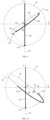
- FIG. 8 is a structural schematic view illustrating the sliding shaft and the sliding rail in a fourth embodiment of the present disclosure
- FIG. 9 is a structural schematic view illustrating the sliding shaft and the sliding rail in a fifth embodiment of the present disclosure.
- the expression of widths of the sliding shaft and the sliding rail is omitted, and the central axis of the sliding shaft is configured to represent the sliding shaft and the center line of the sliding rail is configured to represent the sliding rail.
- the first connecting member 41 is provided with at least the sliding shaft 411 and the sliding shaft 412
- the second connecting member 42 is provided with at least the sliding rail 421 and the sliding rail 422.
- the sliding shaft 411 is connected to the sliding rail 421 and may move along the sliding rail 421
- the sliding shaft 412 is connected to the sliding rail 422 and may move along the sliding rail 422.
- the sliding rail 421 linearly extends, and the sliding rail 422 extends along an ellipse.
- the sliding rail 421 is perpendicular to the plane 221 where the opening 22 is located, and a part of the sliding rail 422 away from the box body 20 is away from the pivoting side 23 relative to the sliding rail 421. Therefore, during the process from blocking the opening 22 by the door body 30 to opening the door body 30 relative to the box body 20, the door body 30 moves towards the target side 24 of the box body 20.
- the second connecting member 42 defines the reference circle 61, the first reference line 62, and a reference ellipse 65.
- the reference circle 61, the first reference line 62 and the reference ellipse 65 are coplanar.
- the center O of the reference circle 61 is located on the first reference line 62.
- the center O coincides with a center of the reference ellipse 65.
- the sliding rail 421 linearly extends along the first reference line 62, and the sliding rail 422 extends along the reference ellipse 65.
- the sliding shaft 411 moves along the sliding rail 421, and the sliding shaft 412 moves along the sliding rail 422, so that the door body 30 moves towards the target side 24 of the box body 20.
- the hinge assembly 40 under the action of the hinge assembly 40, during the process from blocking the opening 22 by the door body 30 to opening the door body 30 relative to the box body 20, the door body 30 moves towards the target side 24 of the box body 20. Therefore, the extent to which the door body 30 exceeds the outer sidewall 25 of the box body 20 reduces, which may reduce the risk of the door body 30 interfering with and colliding with the external structure during rotating the door body 30. In other words, the present embodiment reduces the gap between the box device and the external structure located next to the box device to the micro-slit or even seamless level, which facilitates the embedded installation of the box device.
- the extension of the sliding rail along the reference ellipse means that the center line of the sliding rail coincides with the reference ellipse.
- the center of the ellipse is located on the sliding rail 421.
- the sliding shaft 411 and the sliding shaft 412 are away from the opening 22 relative to the center of the ellipse, and the sliding rail 422 extends along the direction toward the pivoting side 23 and the direction toward the box body 20.
- the second connecting member 42 further defines the second reference line 63, a first coordinate axis X, and a second coordinate axis Y
- the second reference line 63 is coplanar with the first reference line 62 and also intersect with the first reference line 62 on the center O of the reference circle 61.
- An origin of a coordinate system defined by the first coordinate axis X and the second coordinate axis Y is the center O of the reference circle 61.
- the minimum distance from the central axis of the sliding shaft 411 to the plane 221 where the opening 22 is located and the minimum distance from the central axis of the sliding shaft 412 to the plane 221 where the opening 22 is located are greater than or equal to the minimum distance the from the center O of circle to the plane 221 where the opening 22 is located.
- the central axis of the sliding shaft 411 is located on the intersection point of the first reference line 62 and the reference circle 61. That is, the starting point of the sliding shaft 411 is located on the intersection point of the first reference line 62 and the reference circle 61.
- the central axis of the sliding shaft 412 is located on the intersection point of the reference ellipse 65 and the second reference line 63. That is, the starting point of the sliding shaft 412 is located on the intersection point of the reference ellipse 65 and the second reference line 63.
- the door body 30 may move according to the set trajectory.
- the sliding rail 422 bends along a direction toward the box body 20.
- the second connecting member 42 further defines a reference point 66, and the reference point 66 is located on the second reference line 63.
- a connecting line between the reference point 66 and the intersection point of the first reference line 62 and the reference circle 61 is perpendicular to the second reference line 63.
- the starting point of the sliding shaft 412 is away from the center O of the reference circle 61 relative to the reference point 66.
- the sliding rail 422 is located on the side of the second reference line 63 facing the target side 24, as illustrated in FIG. 2 and FIG. 8 .
- the sliding rail 422 bends along a direction away from the box body 20. In some embodiments, the starting point of the sliding shaft 412 is closer to the center O of the reference circle 61 relative to the reference point 66. When the door body 30 blocks the opening 22, the sliding rail 422 is located on the side of the second reference line 63 away from the target side 24, as illustrated in FIG. 2 and FIG. 9 .
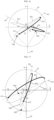
- FIG. 10 is a structural schematic view illustrating the sliding shaft and the sliding rail in a sixth embodiment of the present disclosure
- FIG. 11 is a structural schematic view illustrating the sliding shaft and the sliding rail in a seventh embodiment of the present disclosure.
- the first connecting member 41 is provided with at least the sliding shaft 411 and the sliding shaft 412
- the second connecting member 42 is provided with at least the sliding rail 421 and the sliding rail 422.
- the sliding shaft 411 is connected to the sliding rail 421 and may move along the sliding rail 421
- the sliding shaft 412 is connected to the sliding rail 422 and may move along the sliding rail 422.
- the sliding rail 421 linearly extends, and the sliding rail 422 extends along an ellipse.
- the sliding rail 421 is perpendicular to the plane 221 where the opening 22 is located, and the part of the sliding rail 422 away from the box body 20 is close to the pivoting side 23 relative to the sliding rail 421. Therefore, during the process from blocking the opening 22 by the door body 30 to opening the door body 30 relative to the box body 20, the door body 30 moves towards the target side 24 of the box body 20.
- the second connecting member 42 defines the reference circle 61, the first reference line 62, and the reference ellipse 65.
- the reference circle 61, the first reference line 62 and the reference ellipse 65 are coplanar.
- the center O of the reference circle 61 is located on the first reference line 62.
- the center O coincides with the center of the reference ellipse 65.
- the sliding rail 421 linearly extends along the first reference line 62, and the sliding rail 422 extends along the reference ellipse 65.
- the sliding shaft 411 moves along the sliding rail 421, and the sliding shaft 412 moves along the sliding rail 422, so that the door body 30 moves towards the target side 24 of the box body 20.
- the hinge assembly 40 under the action of the hinge assembly 40, during the process from blocking the opening 22 by the door body 30 to opening the door body 30 relative to the box body 20, the door body 30 moves towards the target side 24 of the box body 20. Therefore, the extent to which the door body 30 exceeds the outer sidewall 25 of the box body 20 reduces, which may reduce the risk of the door body 30 interfering with and colliding with the external structure during rotating the door body 30. In other words, the present embodiment reduces the gap between the box device and the external structure located next to the box device to the micro-slit or even seamless level, which facilitates the embedded installation of the box device.
- the center of the ellipse is located on the sliding rail 421.
- the sliding shaft 411 and the sliding shaft 412 are away from the opening 22 relative to the center of the ellipse.
- the sliding rail 422 bends along the direction toward the pivoting side 23 and the direction away from the box body 20.
- the second connecting member 42 further defines the second reference line 63, the first coordinate axis X, and the second coordinate axis Y
- the second reference line 63 is coplanar with the first reference line 62 and also intersect with the first reference line 62 on the center O of the reference circle 61.
- the origin of the coordinate system defined by the first coordinate axis X and the second coordinate axis Y is the center O of of the reference circle 61.
- the minimum distance from the central axis of the sliding shaft 411 to the plane 221 where the opening 22 is located and the minimum distance from the central axis of the sliding shaft 412 to the plane 221 where the opening 22 is located are greater than or equal to the minimum distance from the center O of circle to the plane 221 where the opening 22 is located.
- the central axis of the sliding shaft 411 is located on the intersection point of the first reference line 62 and the reference circle 61. That is, the starting point of the sliding shaft 411 is located on the intersection point of the first reference line 62 and the reference circle 61.
- the central axis of the sliding shaft 412 is located on the intersection point of the reference ellipse 65 and the second reference line 63. That is, the starting point of the sliding shaft 412 is located on the intersection point of the reference ellipse 65 and the second reference line 63.
- the door body 30 may move according to the set trajectory.
- a connecting line is formed between the sliding shaft 412 and the center of the ellipse, and the sliding rail 422 is located on a side of the connecting line away from the box body 20.
- the second connecting member 42 further defines the reference point 66, and the reference point 66 is located on the second reference line 63.
- the connecting line between the reference point 66 and the intersection point of the first reference line 62 and the reference circle 61 is perpendicular to the second reference line 63.
- the starting point of the sliding shaft 412 is away from the center O of the reference circle 61 relative to the reference point 66.
- the connecting line is formed between the sliding shaft 412 and the center of the ellipse, and the sliding rail 422 is located on a side of the connecting line facing the box body 20.
- the starting point of the sliding shaft 412 is closer to the center O of the reference circle 61 relative to the reference point 66.
- the sliding rail 422 is located on the side of the second reference line 63 away from the target side 24, as illustrated in FIG. 2 and FIG. 11 .
- FIG. 12 is a structural schematic view illustrating the sliding shaft and the sliding rail in an eighth embodiment of the present disclosure
- FIG. 13 is a structural schematic view illustrating the sliding shaft and the sliding rail in a ninth embodiment of the present disclosure.
- the first connecting member 41 is provided with at least the sliding shaft 411 and the sliding shaft 412
- the second connecting member 42 is provided with at least the sliding rail 421 and the sliding rail 422.
- the sliding shaft 411 is connected to the sliding rail 421 and may move along the sliding rail 421
- the sliding shaft 412 is connected to the sliding rail 422 and may move along the sliding rail 422.
- the sliding rail 421 linearly extends, and the sliding rail 422 extends along the ellipse.
- the sliding rail 421 tilts relative to the plane 221 where the opening 22 is located, and the part of the sliding rail 422 away from the box body 20 is away from the pivoting side 23 relative to the sliding rail 421. Therefore, during the process from blocking the opening 22 by the door body 30 to opening the door body 30 relative to the box body 20, the door body 30 moves towards the target side 24 of the box body 20.
- the second connecting member 42 defines the reference circle 61, the first reference line 62, the second reference line 63, and the reference ellipse 65.
- the reference circle 61, the first reference line 62, the second reference line 63, and the reference ellipse 65 are coplanar.
- the first reference line 62 and the second reference line 63 intersect on the center O of the reference circle 61.
- the center O of the reference circle 61 coincides with the center of the reference ellipse 65.
- the sliding rail 421 linearly extends along the second reference line 63, and the sliding rail 422 extends along the reference ellipse 65.
- the sliding shaft 411 moves along the sliding rail 421, and the sliding shaft 412 moves along the sliding rail 422, so that the door body 30 moves towards the target side 24 of the box body 20.
- the hinge assembly 40 under the action of the hinge assembly 40, during the process from blocking the opening 22 by the door body 30 to opening the door body 30 relative to the box body 20, the door body 30 moves towards the target side 24 of the box body 20. Therefore, the extent to which the door body 30 exceeds the outer sidewall 25 of the box body 20 reduces, which may reduce the risk of the door body 30 interfering with and colliding with the external structure during rotating the door body 30. In other words, the present embodiment reduces the gap between the box device and the external structure located next to the box device to the micro-slit or even seamless level, which facilitates the embedded installation of the box device.
- the second connecting member 42 further defines a third reference line 64, the first coordinate axis X, and the second coordinate axis Y
- the third reference line 64 is coplanar with the first reference line 62 and also intersect with the first reference line 62 on the center O of the reference circle 61.
- the origin of the coordinate system defined by the first coordinate axis X and the second coordinate axis Y is the center O of the reference circle 61.
- the minimum distance from the central axis of the sliding shaft 411 to the plane 221 where the opening 22 is located and the minimum distance from the central axis of the sliding shaft 412 to the plane 221 where the opening 22 is located are greater than or equal to the minimum distance the from the center O of circle to the plane 221 where the opening 22 is located.
- the central axis of the sliding shaft 411 and the second reference line 63 forms the intersection point
- the first reference line 62 and the reference circle 61 forms the intersection point
- the connecting line between these two intersection points is perpendicular to the second reference line 63.
- the connecting line between the starting point of the sliding shaft 411 and the intersection point of the first reference line 62 and the reference circle 61 is perpendicular to the second reference line 63.
- the central axis of the sliding shaft 412 is located on the intersection point of the reference ellipse 65 and the third reference line 64. That is, the starting point of the sliding shaft 412 is located on the intersection point of the reference ellipse 65 and the third reference line 64.
- the door body 30 may move according to the set trajectory.
- the sliding rail 422 bends along the direction toward the box body 20.
- the second connecting member 42 further defines the reference point 66, and the reference point 66 is located on the second reference line 63.
- the connecting line between the reference point 66 and the intersection point of the first reference line 62 and the reference circle 61 is perpendicular to the third reference line 64.
- the starting point of the sliding shaft 412 is away from the center O of the reference circle 61 relative to the reference point 66.
- the sliding rail 422 is located on a side of the third reference line 64 facing the target side 24, as illustrated in FIG. 2 and FIG. 12 .
- the sliding rail 422 bends along the direction away from the box body 20. In some embodiments, the starting point of the sliding shaft 412 is closer to the center O of the reference circle 61 relative to the reference point 66. When the door body 30 blocks the opening 22, the sliding rail 422 is located on the side of the third reference line 64 away from the target side 24, as illustrated in FIG. 2 and FIG. 13 .
- the sliding rail 421 when the door body 30 blocks the opening 22, the sliding rail 421 extends along the direction toward the pivoting side 23 and the direction away from the box body 20.
- the sliding shaft 411 is located on the side of the first reference line 62 away from the target side 24. That is, the starting point of the sliding shaft 411 is located on the side of the first reference line 62 away from the target side 24, as illustrated in FIGS. 12 and 13 .
- the sliding rail 421 extends along the direction toward the target side 24 and the direction away from the box body 20.
- the sliding shaft 411 is located on the side of the first reference line 62 facing the target side 24.
- the starting point of the sliding shaft 411 is located on the side of the first reference line 62 facing the target side 24. In this way, under the action of the hinge assembly 40, during the process from blocking the opening 22 by the door body 30 to opening the door body 30 relative to the box body 20, the door body 30 may move according to the set trajectory.
- FIG. 14 is a structural schematic view illustrating the sliding shaft and the sliding rail in a tenth embodiment of the present disclosure
- FIG. 15 is a structural schematic view illustrating the sliding shaft and the sliding rail in an eleventh embodiment of the present disclosure.
- the first connecting member 41 is provided with at least the sliding shaft 411 and the sliding shaft 412
- the second connecting member 42 is provided with at least the sliding rail 421 and the sliding rail 422.
- the sliding shaft 411 is connected to the sliding rail 421 and may move along the sliding rail 421
- the sliding shaft 412 is connected to the sliding rail 422 and may move along the sliding rail 422.
- the second connecting member 42 defines the reference circle 61, the first reference line 62, the second reference line 63, and the reference ellipse 65.
- the reference circle 61, the first reference line 62, the second reference line 63, and the reference ellipse 65 are coplanar.
- the first reference line 62 and the second reference line 63 intersect on the center O of the reference circle 61.
- the center O of the reference circle 61 coincides with the center of the reference ellipse 65.
- the sliding rail 421 linearly extends along the second reference line 63, and the sliding rail 422 extends along the reference ellipse 65.
- the sliding shaft 411 moves along the sliding rail 421, and the sliding shaft 412 moves along the sliding rail 422, so that the door body 30 moves towards the target side 24 of the box body 20.
- the hinge assembly 40 under the action of the hinge assembly 40, during the process from blocking the opening 22 by the door body 30 to opening the door body 30 relative to the box body 20, the door body 30 moves towards the target side 24 of the box body 20. Therefore, the extent to which the door body 30 exceeds the outer sidewall 25 of the box body 20 reduces, which may reduce the risk of the door body 30 interfering with and colliding with the external structure during rotating the door body 30. In other words, the present embodiment reduces the gap between the box device and the external structure located next to the box device to the micro-slit or even seamless level, which facilitates the embedded installation of the box device.
- the center of the ellipse is located on the sliding rail 421.
- the sliding shaft 411 and the sliding shaft 412 are away from the opening 22 relative to the center of the ellipse, and the sliding rail 422 bends along the direction toward the pivoting side 23 and the direction away from the box body 20.
- the second connecting member 42 further defines a third reference line 64, the first coordinate axis X, and the second coordinate axis Y
- the third reference line 64 is coplanar with the first reference line 62 and also intersect with the first reference line 62 on the center O of the reference circle 61.
- the origin of the coordinate system defined by the first coordinate axis X and the second coordinate axis Y is the center O of of the reference circle 61.
- the minimum distance from the central axis of the sliding shaft 411 to the plane 221 where the opening 22 is located and the minimum distance from the central axis of the sliding shaft 412 to the plane 221 where the opening 22 is located are greater than or equal to the minimum distance the from the center O of circle to the plane 221 where the opening 22 is located.
- the central axis of the sliding shaft 411 and the second reference line 63 forms the intersection point
- the first reference line 62 and the reference circle 61 forms the intersection point
- the connecting line between these two intersection points is perpendicular to the second reference line 63.
- the connecting line between the starting point of the sliding shaft 411 and the intersection point of the first reference line 62 and the reference circle 61 is perpendicular to the second reference line 63.
- the central axis of the sliding shaft 412 is located on the intersection point of the reference ellipse 65 and the third reference line 64. That is, the starting point of the sliding shaft 412 is located on the intersection point of the reference ellipse 65 and the third reference line 64.
- the door body 30 may move according to the set trajectory.
- the sliding rail 422 when the door body 30 blocks the opening 22, the sliding rail 422 is located on the side of the connecting line between the sliding shaft 412 and the center of the ellipse away from the box body 20.
- the second connecting member 42 further defines the reference point 66, and the reference point 66 is located on the second reference line 63.
- the connecting line between the reference point 66 and the intersection point of the first reference line 62 and the reference circle 61 is perpendicular to the third reference line 64.
- the starting point of the sliding shaft 412 is away from the center O of the reference circle 61 relative to the reference point 66.
- the sliding rail 422 is located on a side of the third reference line 64 facing the target side 24, as illustrated in FIG. 2 and FIG. 14 .
- the sliding rail 422 when the door body 30 blocks the opening 22, the sliding rail 422 is located on the side of the connecting line between the sliding shaft 412 and the center of the ellipse close to the box body 20. In some embodiments, the starting point of the sliding shaft 412 is closer to the center O of the reference circle 61 relative to the reference point 66. When the door body 30 blocks the opening 22, the sliding rail 422 is located on the side of the third reference line 64 away from the target side 24, as illustrated in FIG. 2 and FIG. 15 .
- the sliding rail 421 when the door body 30 blocks the opening 22, the sliding rail 421 extends along the direction toward the target side 24 and the direction away from the box body 20.
- the sliding shaft 411 is located on the side of the first reference line 62 facing the target side 24. That is, the starting point of the sliding shaft 411 is located on the side of the first reference line 62 close to the target side 24. In this way, a larger included angle between the sliding rail 421 and the sliding rail 422 may be ensured, which facilitate the stability of the movement of the sliding shaft 411 and the sliding shaft 412. That is, it ensures the stable movement of the door body 30.
- FIG. 16 is a structural schematic view illustrating the sliding shaft and the sliding rail in a twelfth embodiment of the present disclosure
- FIG. 17 is a structural schematic view illustrating the sliding shaft and the sliding rail in a thirteenth embodiment of the present disclosure.
- the first connecting member 41 is provided with at least the sliding shaft 411 and the sliding shaft 412
- the second connecting member 42 is provided with at least the sliding rail 421 and the sliding rail 422.
- the sliding shaft 411 is connected to the sliding rail 421 and may move along the sliding rail 421
- the sliding shaft 412 is connected to the sliding rail 422 and may move along the sliding rail 422.
- the sliding rail 421 extends along a first reference ellipse 651
- the sliding rail 422 extends along a second reference ellipse 652.
- the part of the sliding rail away from the box body 20 being away from the pivoting side 23 means that the part of the sliding rail away from the box body 20 is farther away from the pivoting side 23 than the part of the sliding rail close to the box body 20.
- the part of the sliding rail away from the box body 20 being close to the pivoting side 23 means that the part of the sliding rail away from the box body 20 is closer to the pivoting side 23 than the part of the sliding rail close to the box body 20.
- the second connecting member 42 defines the reference circle 61, the first reference line 62, the first reference ellipse 651, and the second reference ellipse 652.
- the reference circle 61, the first reference line 62, the first reference ellipse 651, and the second reference ellipse 652 are coplanar.
- the center O of the reference circle 61 is located on the first reference line 62.
- the center of the first reference ellipse 651 and the center of the second reference ellipse 652 all coincide with the center O of the circle.
- the first reference line 62 is perpendicular to the plane 221 where the opening 22 is located, and the part of the first reference ellipse 651 away from the box body 20 is close to the target side 24 relative to the first reference line 62, and the part of the second reference ellipse 652 away from the box body 20 is away from the target side 24 relative to the first reference line 62.
- the sliding rail 421 extends along the first reference ellipse 651, and the sliding rail 422 extends along the second reference ellipse 652.
- the sliding shaft 411 moves along the sliding rail 421, and the sliding shaft 412 moves along the sliding rail 422, so that the door body 30 moves towards the target side 24 of the box body 20.
- the hinge assembly 40 under the action of the hinge assembly 40, during the process from blocking the opening 22 by the door body 30 to opening the door body 30 relative to the box body 20, the door body 30 moves towards the target side 24 of the box body 20. Therefore, the extent to which the door body 30 exceeds the outer sidewall 25 of the box body 20 reduces, which may reduce the risk of the door body 30 interfering with and colliding with the external structure during rotating the door body 30. In other words, the present embodiment reduces the gap between the box device and the external structure located next to the box device to a micro-slit or even seamless level, which facilitates the embedded installation of the box device.
- the sliding shaft 411 when the door body 30 blocks the opening 22, the sliding shaft 411 is away from the opening 22 relative to the center of the first reference ellipse 651, and the sliding rail 421 extends along the direction toward the pivoting side 23 and the direction toward the box body 20.
- the second connecting member 42 further defines the second reference line 63, the first coordinate axis X, and the second coordinate axis Y
- the second reference line 63 is coplanar with the first reference line 62 and also intersect with the first reference line 62 on the center O of the reference circle 61.
- the origin of the coordinate system defined by the first coordinate axis X and the second coordinate axis Y is the center O of the reference circle 61.
- the minimum distance from the central axis of the sliding shaft 411 to the plane 221 where the opening 22 is located is greater than or equal to the minimum distance from the center O of the reference circle 61 to the plane 221 where the opening 22 is located.
- the central axis of the sliding shaft 411 is located on an intersection point of the first reference ellipse 651 and the second reference line 63. That is, the starting point of the sliding shaft 411 is located on the intersection point of the first reference ellipse 651 and the second reference line 63.
- the door body 30 may move according to the set trajectory.
- the sliding rail 421 bends along the direction toward the box body 20.
- the second connecting member 42 further defines a first reference point 661, and the first reference point 661 is located on the second reference line 63.
- a connecting line between the first reference point 661 and the intersection point of the first reference line 62 and the reference circle 61 is perpendicular to the second reference line 63.
- the starting point of the sliding shaft 411 is away from the center O of the reference circle 61 relative to the first reference point 661.
- the sliding rail 421 is located on the side of the second reference line 63 facing the target side 24, as illustrated in the FIG. 2 and FIG. 16 .
- the sliding rail 421 bends along the direction away from the box body 20. In some embodiments, the starting point of the sliding shaft 411 is closer to the center O of the reference circle 61 relative to the first reference point 661. When the door body 30 blocks the opening 22, the sliding rail 421 is located on the side of the second reference line 63 away from the target side 24, as shown in FIG. 2 and FIG. 17 .
- the sliding shaft 412 when the door body 30 blocks the opening 22, the sliding shaft 412 is away from the opening 22 relative to the center of the second reference ellipse 652, and the sliding rail 422 bends along the direction toward the pivoting side 23 and the direction away from the box body 20.
- the second connecting member 42 further defines a third reference line 64.
- the third reference line 64 is coplanar with the first reference line 62 and intersects with the first reference line 62 on the center O of the reference circle 61.
- the minimum distance from the central axis of the sliding shaft 412 to the plane 221 where the opening 22 is located is greater than or equal to the minimum distance from the center O of the reference circle 61 to the plane 221 where the opening 22 is located.
- the central axis of the sliding shaft 412 is located on an intersection point of the second reference ellipse 652 and the third reference line 64. That is, the starting point of the sliding shaft 412 is located on the intersection point of the second reference ellipse 652 and the third reference line 64.
- the door body 30 may move according to the set trajectory.
- the sliding rail 422 when the door body 30 blocks the opening 22, the sliding rail 422 is located on a side of a connecting line between the sliding shaft 412 and the center of the second reference ellipse 652 away from the box body 20.
- the second connecting member 42 further defines a second reference point 662, and the second reference point 662 is located on the third reference line 64.
- the connecting line between the second reference point 662 and the intersection point of the first reference line 62 and the reference circle 61 is perpendicular to the third reference line 64.
- the starting point of the sliding shaft 412 is away from the center O of the reference circle 61 relative to the second reference point 662.
- the sliding rail 422 is located on the side of the third reference line 64 facing the target side 24, as illustrated in the FIG. 2 and FIG. 16 .
- the sliding rail 422 when the door body 30 blocks the opening 22, the sliding rail 422 is located on a side of the connecting line between the sliding shaft 412 and the center of the second reference ellipse 652 facing the box body 20. In some embodiments, the starting point of the sliding shaft 412 is close to the center O of the reference circle 61 relative to the second reference point 662. When the door body 30 blocks the opening 22, the sliding rail 422 is located on the side of the third reference line 64 away from the target side 24, as illustrated in FIG. 2 and FIG. 17 .
- FIG. 18 is a structural schematic view illustrating the sliding shaft and the sliding rail in a fourteenth embodiment of the present disclosure
- FIG. 19 is a structural schematic view illustrating the sliding shaft and the sliding rail in a fifteenth embodiment of the present disclosure.
- the first connecting member 41 is provided with at least the sliding shaft 411 and the sliding shaft 412
- the second connecting member 42 is provided with at least the sliding rail 421 and the sliding rail 422.
- the sliding shaft 411 is connected to the sliding rail 421 and may move along the sliding rail 421
- the sliding shaft 412 is connected to the sliding rail 422 and may move along the sliding rail 422.
- the sliding rail 421 extends along the first reference ellipse 651
- the sliding rail 422 extends along the second reference ellipse 652.
- the second connecting member 42 defines the reference circle 61, the first reference line 62, the first reference ellipse 651, and the second reference ellipse 652.
- the reference circle 61, the first reference line 62, the first reference ellipse 651, and the second reference ellipse 652 are coplanar.
- the center O of the reference circle 61 is located on the first reference line 62.
- the center of the first reference ellipse 651 and the center of the second reference ellipse 652 all coincide with the center O of the circle.
- the first reference line 62 is perpendicular to the plane 221 where the opening 22 is located, and the part of the first reference ellipse 651 away from the box body 20 and the part of the second reference ellipse 652 away from the box body 20 are close to the target side 24 relative to the first reference line 62.
- the sliding rail 421 extends along the first reference ellipse 651, and the sliding rail 422 extends along the second reference ellipse 652.
- the sliding shaft 411 moves along the sliding rail 421, and the sliding shaft 412 moves along the sliding rail 422, so that the door body 30 moves towards the target side 24 of the box body 20.
- the hinge assembly 40 under the action of the hinge assembly 40, during the process from blocking the opening 22 by the door body 30 to opening the door body 30 relative to the box body 20, the door body 30 moves towards the target side 24 of the box body 20. Therefore, the extent to which the door body 30 exceeds the outer sidewall 25 of the box body 20 reduces, which may reduce the risk of the door body 30 interfering with and colliding with the external structure during rotating the door body 30. In other words, the present embodiment reduces the gap between the box device and the external structure located next to the box device to the micro-slit or even seamless level, which facilitates the embedded installation of the box device.
- the first reference ellipse 651 is different from the second reference ellipse 652. That is, the degree to which the part of the first reference ellipse 651 away from the box 20 is close to the target side 24 is different from the degree to which the part of the second reference ellipse 652 away from the box 20 is close to the target side 24.
- the sliding shaft 411 when the door body 30 blocks the opening 22, the sliding shaft 411 is away from the opening 22 relative to the center of the first reference ellipse 651, and the sliding rail 421 extends along the direction toward the pivoting side 23 and the direction toward the box body 20.
- the second connecting member 42 further defines the second reference line 63, the first coordinate axis X, and the second coordinate axis Y
- the second reference line 63 is coplanar with the first reference line 62 and also intersect with the first reference line 62 on the center O of the reference circle 61.
- the origin of the coordinate system defined by the first coordinate axis X and the second coordinate axis Y is the center O of the reference circle 61.
- the minimum distance from the central axis of the sliding shaft 411 to the plane 221 where the opening 22 is located is greater than or equal to the minimum distance from the center O of the reference circle 61 to the plane 221 where the opening 22 is located.
- the central axis of the sliding shaft 411 is located on an intersection point of the first reference ellipse 651 and the second reference line 63. That is, the starting point of the sliding shaft 411 is located on the intersection point of the first reference ellipse 651 and the second reference line 63.
- the door body 30 may move according to the set trajectory.
- the sliding rail 421 bends along the direction toward the box body 20.
- the second connecting member 42 further defines a first reference point 661, and the first reference point 661 is located on the second reference line 63.
- a connecting line between the first reference point 661 and the intersection point of the first reference line 62 and the reference circle 61 is perpendicular to the second reference line 63.
- the starting point of the sliding shaft 411 is away from the center O of the reference circle 61 relative to the first reference point 661.
- the sliding rail 421 is located on the side of the second reference line 63 facing the target side 24, as illustrated in the FIG. 2 and FIG. 18 .
- the sliding rail 421 bends along the direction away from the box body 20. In some embodiments, the starting point of the sliding shaft 411 is closer to the center O of the reference circle 61 relative to the first reference point 661. When the door body 30 blocks the opening 22, the sliding rail 421 is located on the side of the second reference line 63 away from the target side 24, as shown in FIG. 2 and FIG. 19 .
- the sliding shaft 412 when the door body 30 blocks the opening 22, the sliding shaft 412 is away from the opening 22 relative to the center of the second reference ellipse 652, and the sliding rail 422 extends along the direction toward the pivoting side 23 and the direction toward the box body 20.
- the second connecting member 42 further defines the third reference line 64.
- the third reference line 64 is coplanar with the first reference line 62 and intersects with the first reference line 62 on the center O of the reference circle 61.
- the minimum distance from the central axis of the sliding shaft 412 to the plane 221 where the opening 22 is located is greater than or equal to the minimum distance from the center O of the reference circle 61 to the plane 221 where the opening 22 is located.
- the central axis of the sliding shaft 412 is located on an intersection point of the second reference ellipse 652 and the third reference line 64. That is, the starting point of the sliding shaft 412 is located on the intersection point of the second reference ellipse 652 and the third reference line 64.
- the door body 30 may move according to the set trajectory.
- the sliding rail 422 bends along the direction toward the box body 20.
- the second connecting member 42 further defines the second reference point 662
- the second reference point 662 is located on the third reference line 64.
- the connecting line between the second reference point 662 and the intersection point of the first reference line 62 and the reference circle 61 is perpendicular to the third reference line 64.
- the starting point of the sliding shaft 412 is away from the center O of the reference circle 61 relative to the second reference point 662.
- the sliding rail 422 is located on the side of the third reference line 64 facing the target side 24, as illustrated in the FIG. 2 and FIG. 18 .
- the sliding rail 422 bends along the direction away from the box body 20.
- the starting point of the sliding shaft 412 is close to the center O of the reference circle 61 relative to the second reference point 662.
- the sliding rail 422 is located on the side of the third reference line 64 away from the target side 24, as illustrated in FIG. 2 and FIG. 19 .
- the starting point of the sliding shaft 411 is away from the center O of the reference circle 61 relative to the first reference point 661, and the starting point of the sliding shaft 412 is close to the center O of the reference circle 61 relative to the second reference point 662, as shown in FIG. 18 .
- the starting point of the sliding shaft 411 is close to the center O of the reference circle 61 relative to the first reference point 661, and the starting point of the sliding shaft 412 is away from the center O of the reference circle 61 relative to the second reference point 662, as shown in FIG. 19 .
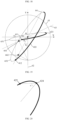
- FIG. 20 is a structural schematic view illustrating the sliding rail extending along a reference ellipse in some embodiments of the present disclosure.
- the sliding rail (including the reference ellipse of the above embodiments) extending along the ellipse intersects with the major axis of the ellipse at an inflection point 424.
- An included angle ⁇ between the major axis of the ellipse and a connecting line between any target point 425 and the inflection point 424 is greater than or equal to 10°.
- FIG. 21 is a structural schematic view illustrating the sliding shaft and the sliding rail in a sixteenth embodiment of the present disclosure.
- the sliding rail 421 where the sliding shaft 411 is located has a first tangent line P1
- the sliding rail 422 where the sliding shaft 412 is located has a second tangent line P2.
- An angle ⁇ between the first tangent line P1 and the second tangent line P2 is greater than or equal to 10°, which facilitates the stability of movement of the door body.
- FIG. 22 is a structural schematic view of a part of the door body in the present disclosure.
- the setting positions of the sliding rails may be described below based on the door body 30 being in the closed state.
- the minimum distances from the sliding rail to the inner edge 31, the outer edge 32, and the side edge 33 are all greater than or equal to 6 mm.
- the minimum distances from any one of the sliding rails including the sliding rail 421, the sliding rail 422, and the sliding rail 423 in the above embodiments to the inner edge 31, the outer edge 32, and the side edge 33 are all greater than or equal to 6 mm. In this way, enough space may be reserved for the design and manufacture of the sliding rail, which facilitates the engineering design and manufacture of the hinge assembly 40.
- different sliding rails may be spaced apart from each other, that is, there is no intersection between different sliding rails.
- any two of the sliding rails including the sliding rail 421, the sliding rail 422, and the sliding rail 423 in the above embodiments are spaced apart from each other. In this way, it may ensure that at any time, different sliding shafts are in different sliding rails, which may avoid unstable movements of the sliding shafts caused by different sliding shafts being in the same sliding rail. Thus, it ensures the stability of movement of the door body.
- FIG. 23 is a structural schematic view of another part of the box device shown in FIG. 2 .
- the size and the setting position of the reference circle 61 may be described below based on the door body 30 being in the closed state.
- the maximum distance that the outer side edge 35 of the door body 30 exceeds the outer sidewall 25 of the box body 20 gradually reduces.
- the reference circle 61 moving towards the target side 24 of the box body 20 may increase the amount of movement of the door body 30 towards the target side 24 during opening the door body 30.
- a radius of the reference circle 61 is defined as R
- a distance from the center O of the reference circle 61 to the side edge 33 is defined as N
- R ⁇ N ⁇ 100 mm it may ensure that when the door body 30 is opened under the action of the hinge assembly 40, the maximum distance that the outer side edge 35 of the door body 30 exceeds the outer side-wall 25 of the box body 20 is controlled within 4 mm as required by the industry.
- the amount of movement of the door body 30 towards the target side 24 is controlled within a reasonable range, which reduces the risk of interference and collision between the second inner side edge 36 of the door body 30 and other structures, and reserves enough space for the user to open the door body 30.
- the distance from the center O of the reference circle 61 to the side edge 33 is at least equal to the radius R of the reference circle 61, which facilitates the design and manufacture of the sliding shaft and the sliding rail of the hinge assembly 40.
- the reference circle 61 moves from the outer edge 32 to the inner edge 31, the amount of movement of the outer side edge 35 of the door body 30 towards the box body 20 gradually increases during opening the door body 30, and the risk of interference and collision between the outer side edge 35 and box body 20 gradually increases.
- the center O of the reference circle 61 is close to the opening 22 relative to the center of the side edge 33, the outer side edge 35 of the door body 30 may interfere with and collide with the box body 20 during opening the door body 30.
- a length of the side edge 33 of the door body 30 in the first direction Z1 is defined as D
- a distance from the center O of the reference circle 61 to the outer edge 32 is defined as W
- R ⁇ W ⁇ (1/2)D the distance from the center O of the reference circle 61 to the outer edge 32 is at least equal to the radius R of the reference circle 61, which facilitates the design and manufacture of the sliding shaft and the sliding rail of the hinge assembly 40.
- the amount of movement of the first inner side edge 34 of the door body 30 towards the box body 20 gradually increases during opening the door body 30, and the risk of interference and collision between the first inner side edge 34 and the box body 20 gradually increases.
- the reference circle 61 moves from the outer edge 32 to the inner edge 31, the amount of movement of the first inner side edge 34 of the door body 30 towards the box body 20 does not significantly change during opening the door body 30. In this case, the selection of the position of the reference circle 61 has less influence on the amount of interference between the first inner side edge 34 and the box body 20, and more consideration is given to the design and manufacture of the hinge assembly 40.
- the radius of the reference circle 61 is defined as R
- the length of the side edge 33 in the first direction Z1 is defined as D
- the distance from the center O of the reference circle 61 to the outer edge 32 is defined as W
- R ⁇ W ⁇ D the distance from the center O of the reference circle 61 to the outer edge 32.
- the amount of movement of the third inner side edge 51 of the door seal 50 towards the box body 20 gradually increases during opening the door body 30, resulting in a gradual increase in the extrusion amount of the door seal 50.
- the extrusion amount of the door seal 50 is controlled within 5 mm. That is, it is required that the maximum amount of movement of the third inner side edge 51 of the door seal 50 towards the box body 20 is less than or equal to 5 mm during opening the door body 30.
- the distance from the center O of the reference circle 61 to the side edge 33 is defined as N, and 15 mm ⁇ N ⁇ 100 mm. In this way, it may ensure that the maximum amount of movement of the third inner side edge 51 of the door seal 50 towards the box body 20 is less than or equal to 5 mm during opening the door body 30, which facilitates improving the reliability and stability of the door seal 50.
- the distance from the center O of the reference circle 61 to the side edge 33 is at least 15 mm, which facilitates the design and manufacture of the sliding shaft and the sliding rail of the hinge assembly 40.
- the reference circle 61 moves from the outer edge 32 to the inner edge 31, the amount of movement of the third inner side edge 51 of the door seal 50 towards the box body 20 does not significantly change during opening the door body 30. In this case, the selection of the position of the reference circle 61 has less influence on the extrusion amount of the door seal 50, and more consideration is given to the design and manufacture of the hinge assembly 40.
- the radius of the reference circle 61 is defined as R
- the length of the side edge 33 in the first direction Z1 is defined as D
- the distance from the center O of the reference circle 61 to the outer edge 32 is defined as W
- R ⁇ W ⁇ D is defined as W
- the selection of the position of the reference circle 61 is more flexible, and the sliding shaft and the sliding rail may be conveniently designed and manufactured. It may be adapted to the application scene where the maximum opening angle of the door seal 50 reaches 150°.
- a length of the door body 30 in the first direction Z1 is defined as H, that is, a width of the door body 30 is defined as H, and 35 mm ⁇ H ⁇ 100 mm.
- a length of the door body 30 in the second direction Z2 is defined as L, that is, a length of the door body 30 is defined as L, and 300 mm ⁇ L ⁇ 700 mm.
- the minimum distance from the reference circle 61 to the outer edge 32 is defined as M, and 0 mm ⁇ M ⁇ 15 mm.
- the size and setting position of the reference circle 61 are reasonably selected, so as to reasonably determine the setting positions of the sliding shaft and the sliding rail.
- the sliding shaft and sliding rail designed and manufactured in this way may guide the door body 30 to move according to the trajectory set above.
- the outer side edge 35 of the door body 30 moves according to the trajectory A1, and the maximum distance g max that the outer side edge 35 exceeds the outer sidewall 25 of the box body 20 may be controlled within 1 mm.
- the first inner side edge 34 of the door body 30 moves according to the trajectory A2, the amount of movement of the first inner side edge 34 towards the box body 20 is small, and the risk of interference between the first inner side edge 34 and the box body 20 is low.
- the second inner side edge 36 of the door body 30 moves according to the trajectory A3, and the maximum distance that the second inner side edge 36 exceeds the outer sidewall 25 of the box body 20 may be controlled within 3 mm.
- the third inner side edge 51 of the door seal 50 moves according to the trajectory A4, and the amount of movement of the third inner side edge 51 towards the box body 20 is small, that is, the extrusion amount of the door seal 50 is small.
- connection and “stacking” and the like should be broadly understood.
- connection may be a fixed connection, a detachable connection, or an integrated connection; it may be a direct connection or an indirect connection through an intermediate medium; it may be the internal communication of two elements or the interaction relationship between two elements.
- connection may be a fixed connection, a detachable connection, or an integrated connection; it may be a direct connection or an indirect connection through an intermediate medium; it may be the internal communication of two elements or the interaction relationship between two elements.
Landscapes
- Engineering & Computer Science (AREA)
- Mechanical Engineering (AREA)
- Chemical & Material Sciences (AREA)
- Combustion & Propulsion (AREA)
- Physics & Mathematics (AREA)
- Thermal Sciences (AREA)
- General Engineering & Computer Science (AREA)
- Refrigerator Housings (AREA)
Abstract
Description
- The present application claims priority to
Chinese Patent Application No. 202111275431.5, entitled "BOX DEVICE", filed October 29, 2021 - The present disclosure relates to the technical field of hinges, and in particular to a box device.
- A box device includes a door body and a box body. When the door body is opened relative to the box body, the door body may exceed an outer sidewall of the box device, which may cause interference between the door body and an installation environment of the box device. For example, in the case of embedded installation of the box device, a part of the door body exceeding the outer sidewall of the box device may interfere with a wall embedded by the box device.
- A main technical problem to be solved by the present disclosure is to provide a box device, which may reduce the risk of interference and collision of the door body during rotating the door body.
- In order to solve the above technical problem, a technical solution adopted by the present disclosure is to provide a box device. The box device includes a box body internally provided with an accommodating space with an opening. The box device further includes a door body configured to block the opening. The box device further includes a hinge assembly, and the hinge assembly is disposed on a pivoting side of the box body and pivotally connecting the box body to the door body. The hinge assembly includes a first connecting member and a second connecting member, the first connecting member is disposed on one of the box body and the door body, and the second connecting member is disposed on the other of the box body and the door body. The first connecting member is at least provided with a first sliding shaft and a second sliding shaft, and the second connecting member is at least provided with a first sliding rail and a second sliding rail. The first sliding shaft is connected to the first sliding rail and is able to move along the first sliding rail, and the second sliding shaft is connected to the second sliding rail and is able to move along the second sliding rail. The first sliding rail linearly extends, and the second sliding rail extends along an ellipse. When the door body blocks the opening, the first sliding rail is perpendicular to a plane where the opening is located, a part of the second sliding rail away from the box body is closer to the pivoting side relative to the first sliding rail, so that the door body moves towards a target side of the box body during a process from blocking the opening by the door body to opening the door body relative to the box body. The opening includes two opposite sides, the pivoting side is disposed on one of the two opposite sides, and the target side is disposed on the other of the two opposite sides.
- In some embodiments, a center of the ellipse is located on the first sliding rail.
- In some embodiments, the first sliding shaft and the second sliding shaft are away from the opening relative to the center of the ellipse when the door body blocks the opening.
- In some embodiments, the second sliding rail is located on a side of a connecting line between the second sliding shaft and a center of the ellipse away from the box body when the door body blocks the opening.
- In some embodiments, the second sliding rail is located on a side of a connecting line between the second sliding shaft and a center of the ellipse facing the box body when the door body blocks the opening.
- In some embodiments, the second sliding rail bends along a direction toward the pivoting side and a direction away from the box body when the door body blocks the opening.
- In some embodiments, an end surface of the door body facing the hinge assembly includes an inner edge and an outer edge, the inner edge and the outer edge are disposed at intervals along a first direction and extend along a second direction, the first direction is perpendicular to the second direction, and the inner edge is close to the box body relative to the outer edge when the door body blocks the opening.
- In some embodiments, the end surface of the door body facing the hinge assembly further includes a side edge, the inner edge is connected to the outer edge by the side edge, and the side edge extends along the first direction.
- In some embodiments, the first direction is perpendicular to the plane where the opening is located, minimum distances from any one of the first sliding rail, the second sliding rail, and a third sliding rail to the inner edge, the outer edge, and the side edge are all greater than or equal to 6 mm.
- In some embodiments, the first sliding rail where the first sliding shaft is located has a first tangent, the second sliding rail where the second sliding shaft is located has a second tangent, and an included angle between the first tangent and the second tangent is greater than or equal to 10°.
- In some embodiments, the second sliding rail intersects with a major axis of the ellipse at an inflection point.
- In some embodiments, the second sliding rail has a target point, and the target point is located on a side of a minor axis of the ellipse facing the inflection point.
- In some embodiments, an included angle between the major axis of the ellipse and a connecting line between the target point and the inflection point is greater than or equal to 10°.
- In some embodiments, the first sliding rail and the second sliding rail are spaced apart from each other.
- In some embodiments, the second connecting member defines a reference circle, a center of the reference circle is located on a center line of the first sliding rail, and a center of the ellipse coincides with the center of the reference circle.
- In some embodiments, the side edge is perpendicular to the plane where the opening is located, a radius of the reference circle is defined as R, a distance from the center of the reference circle to the side edge is defined as N, and R≤N≤100 mm.
- In some embodiments, a radius of the reference circle is defined as R, a length of the side edge in the first direction is defined as D, a distance from the center of the reference circle to the outer edge is defined as W, and R≤W≤(1/2)D.
- In some embodiments, the side edge is perpendicular to the plane where the opening is located, a distance from the center of the reference circle to the side edge is defined as N, and 15 mm≤N≤100 mm.
- In some embodiments, a radius of the reference circle is defined as R, a length of the side edge in the first direction is defined as D, a distance from the center of the reference circle to the outer edge is defined as W, and R≤W≤D.
- In some embodiments, the second connector defines a reference circle, a center of the reference circle is located on a center line of the first sliding rail, and a center of the ellipse coincides with the center of the reference circle. The end surface of the door body facing the hinge assembly includes the inner edge and the outer edge, and the inner edge and the outer edge are spaced apart from each other along the first direction and extend along the second direction. The first direction is perpendicular to the second direction. When the door body blocks the opening, the inner edge is close to the box body relative to the outer edge. A length of the door body in the first direction is defined as H, and 35mm≤H≤100mm. A length of the door body in the second direction is defined as L, and 300mm≤L≤700mm. A radius of the reference circle is defined as R, and R=(1/3)H. A minimum distance from the reference circle to the outer edge is defined as M, and 0 mm≤M≤15 mm.
- Different from the related art, the effects of the present disclosure are as follows. The hinge assembly of the box device of the present disclosure is provided with the first sliding rail and the second sliding rail. The first sliding rail linearly extends, and the second sliding rail extends along the ellipse. When the door body blocks the opening, the first sliding rail is perpendicular to the plane where the opening is located, the part of the second sliding rail away from the box body is closer to the pivoting side relative to the first sliding rail, so that the door body moves towards the target side of the box body during the process from blocking the opening by the door body to opening the door body relative to the box body. Therefore, the degree of the door body exceeding the outer sidewall of the box body is reduced, which may reduce the risk of interference or collision between the door body and an external structure during rotating the door body.
- The accompanying drawings here are incorporated into the specification and form a part of the present specification. These accompanying drawings illustrate embodiments in accordance with the present disclosure and are configured together with the specification to explain the principles of the present disclosure. In addition, these accompanying drawings and textual descriptions are not intended to limit the scope of the concept of the present disclosure in any way, but to illustrate the concept of the present disclosure for those skilled in the art by referring to specific embodiments.
-
FIG. 1 is a structural schematic view of a refrigeration device in a related art. -
FIG. 2 is a structural schematic view of a box device in some embodiments of the present disclosure. -
FIG. 3 is a structural schematic view illustrating a sliding shaft and a sliding rail in a first embodiment of the present disclosure. -
FIG. 4 is a structural schematic view of a part of the box device shown inFIG. 2 . -
FIG. 5 is a structural schematic view illustrating a process of opening a door body in some embodiments of the present disclosure. -
FIG. 6 is a structural schematic view illustrating the sliding shaft and the sliding rail in a second embodiment of the present disclosure. -
FIG. 7 is a structural schematic view illustrating the sliding shaft and the sliding rail in a third embodiment of the present disclosure. -
FIG. 8 is a structural schematic view illustrating the sliding shaft and the sliding rail in a fourth embodiment of the present disclosure. -
FIG. 9 is a structural schematic view illustrating the sliding shaft and the sliding rail in a fifth embodiment of the present disclosure. -
FIG. 10 is a structural schematic view illustrating the sliding shaft and the sliding rail in a sixth embodiment of the present disclosure. -
FIG. 11 is a structural schematic view illustrating the sliding shaft and the sliding rail in a seventh embodiment of the present disclosure. -
FIG. 12 is a structural schematic view illustrating the sliding shaft and the sliding rail in an eighth embodiment of the present disclosure. -
FIG. 13 is a structural schematic view illustrating the sliding shaft and the sliding rail in a ninth embodiment of the present disclosure. -
FIG. 14 is a structural schematic view illustrating the sliding shaft and the sliding rail in a tenth embodiment of the present disclosure. -
FIG. 15 is a structural schematic view illustrating the sliding shaft and the sliding rail in an eleventh embodiment of the present disclosure. -
FIG. 16 is a structural schematic view illustrating the sliding shaft and the sliding rail in a twelfth embodiment of the present disclosure. -
FIG. 17 is a structural schematic view illustrating the sliding shaft and the sliding rail in a thirteenth embodiment of the present disclosure. -
FIG. 18 is a structural schematic view illustrating the sliding shaft and the sliding rail in a fourteenth embodiment of the present disclosure. -
FIG. 19 is a structural schematic view illustrating the sliding shaft and the sliding rail in a fifteenth embodiment of the present disclosure. -
FIG. 20 is a structural schematic view illustrating the sliding rail extending along a reference ellipse in some embodiments of the present disclosure. -
FIG. 21 is a structural schematic view illustrating the sliding shaft and the sliding rail in a sixteenth embodiment of the present disclosure. -
FIG. 22 is a structural schematic view of a part of the door body in the present disclosure. -
FIG. 23 is a structural schematic view of another part of the box device shown inFIG. 2 . - In order to make the objectives, technical solutions and advantages of the present disclosure clearer, the technical solutions in some embodiments of the present disclosure are clearly and completely described in conjunction with accompanying drawings in some embodiments of the present disclosure. Obviously, the described embodiments are only a part of the embodiments of the present disclosure, and not all embodiments. Based on the embodiments in the present disclosure, all other embodiments obtained by those of ordinary skill in the art without creative effort are within the scope of the present disclosure. In the case of no conflict, the following embodiments and features in the embodiments may be combined with each other.
- As illustrated in
FIG. 1, FIG. 1 is a structural schematic view of a refrigeration device in a related art. - In the related art, a hinge structure is configured for opening and closing a door body of a refrigeration device such as a refrigerator, and usually adopts a single hinge shaft design. For example, a
box body 11 of arefrigerator 10 is provided with ahinge fixing plate 12, and thehinge fixing plate 12 is provided with ahinge shaft 13. Adoor body 14 of therefrigerator 10 defines a shaft hole (not shown in drawing). Thehinge shaft 13 is inserted into the shaft hole, and thehinge shaft 13 may rotate in the shaft hole, so that thedoor body 14 may rotate relative to thebox body 11, thereby achieving the opening and closing of thedoor body 14. - As the home decoration style gradually tends to be integrated, concealed, and simple, the embedded installation of the
refrigerator 10 also emerges as the times require. For example, therefrigerator 10 is embedded in acabinet 15. However, limited by the existing hinge structure adopting the single hinge shaft design, thedoor body 14 exceeds anouter sidewall 111 of thebox body 11 during rotating thedoor body 14 relative to thebox body 11. During rotating thedoor body 14, there is a risk of interference or collision between thedoor body 14 and an external structure (such as the cabinet 15). - Therefore, the embodiments of the present disclosure provide a box device, which may reduce the extent to which the door body exceeds the outer sidewall of the box body during rotating the door body, and may be described in detail below.
- As illustrated in
FIG. 2, FIG. 2 is a structural schematic view of a box device in some embodiments of the present disclosure. - In some embodiments, the box device may be the refrigeration device, such as, the refrigerator or a freezer. In some embodiments, the box device may also be other devices that include the
box body 20 and thedoor body 30, and thedoor body 30 may be rotated relative to thebox body 20. Hereinafter, the box device being the refrigerator is taken as an example for illustration, which is only for the purpose of discussion, and does not limit the specific form or structure of the box device. - The box device includes the
box body 20. Thebox body 20 is a storage medium of the box device, and a user stores objects to be refrigerated or frozen in thebox body 20. In some embodiments, anaccommodating space 21 is defined in thebox body 20, theaccommodating space 21 has anopening 22, and the objects to be refrigerated or frozen are stored in theaccommodating space 21. - The box device further includes the
door body 30 configured for sealing theopening 22 of theaccommodation space 21. When thedoor body 30 blocks theopening 22, that is, thedoor body 30 is in a closed state, and a relatively closed space is formed inside thebox body 20 configured for storing the objects. Thedoor body 30 is rotatably connected to a pivotingside 23 of thebox body 20, that is, thedoor body 30 may rotate relative to thebox body 20. Thebox body 20 also includes atarget side 24, and the pivotingside 23 and thetarget side 24 are respectively disposed on two opposite sides of theopening 22. - The box device further includes a
hinge assembly 40. Thehinge assembly 40 is disposed on the pivotingside 23 of thebox body 20, and thehinge assembly 40 is pivotally connected to thebox body 20 and thedoor body 30, so as to achieve a rotational connection between thebox body 20 and thedoor body 30. In some embodiments, thehinge assembly 40 includes a first connectingmember 41 and a second connectingmember 42. The first connectingmember 41 is disposed on one of thebox body 20 and thedoor body 30, and the second connectingmember 42 is disposed on the other of thebox body 20 and thedoor body 30. The first connectingmember 41 is provided with a sliding shaft, and the second connectingmember 42 is provided with a sliding rail. The sliding shaft is connected to the sliding rail, and the sliding shaft may move along the sliding rail. During rotating thedoor body 30 relative to thebox body 20, the sliding shaft moves along the sliding rail. - The first connecting
member 41 and the second connectingmember 42 may be parts of thebox body 20 and thedoor body 30, that is, the first connectingmember 41 and the second connectingmember 42 may be integrated with thebox body 20 and thedoor body 30. In some embodiments, when the first connectingmember 41 is disposed on thebox body 20 and the second connectingmember 42 is disposed on thedoor body 30, the first connectingmember 41 may be integrated with thebox body 20, and the second connectingmember 42 may be integrated with thedoor body 30. When the sliding rail is in a form of a groove, a surface of thedoor body 30 is recessed to directly form the sliding rail, and the sliding shaft is embedded in the sliding rail. In this case, thedoor body 30 on the position of the sliding rail may be understood as the second connectingmember 42. - In some embodiments, an end surface of the
door body 30 facing thehinge assembly 40 includes aninner edge 31, anouter edge 32, and aside edge 33. Theinner edge 31 and theouter edge 32 are disposed at intervals along a first direction Z1, and both extend along a second direction Z2. When thedoor body 30 blocks theopening 22, theinner edge 31 is closer to thebox body 20 relative to theouter edge 32. Theside edge 33 is located on the pivotingside 23. Theinner edge 31 is connected to theouter edge 32 by theside edge 33, and theside edge 33 extends along the first direction Z1. When thedoor body 30 blocks theopening 22, theside edge 33 is perpendicular to a plane 221 where theopening 22 is located. - The
door body 30 includes a firstinner side edge 34 and anouter side edge 35 on the pivotingside 23. The firstinner side edge 34 and theouter side edge 35 are disposed at intervals along the first direction Z1, and both extend along a third direction Z3. When thedoor body 30 blocks theopening 22, the firstinner side edge 34 is closer to thebox body 20 than theouter side edge 35. The firstinner side edge 34 is connected to an intersection point of theinner edge 31 and theside edge 33. Theouter side edge 35 is connected to an intersection point of theouter edge 32 and theside edge 33. - The
door body 30 further includes a secondinner side edge 36 away from the pivotingside 23. The secondinner side edge 36 extends along the third direction Z3. When thedoor body 30 blocks theopening 22, a plane where both the firstinner side edge 34 and the secondinner side edge 36 are located is parallel to the plane 221 where theopening 22 is located. The user usually grasps the side of thedoor body 30 away from the pivotingside 23 to open thedoor body 30. - Any two of the first direction Z1, the second direction Z2, and the third direction Z3 are perpendicular to each other. When the box device is correctly placed, both the first direction Z1 and the second direction Z2 are horizontal, and the third direction Z3 is vertical. The pivoting
side 23 and thetarget side 24 are disposed opposite to each other along the second direction Z2. InFIG. 2 , the third direction Z3 is perpendicular to a drawing paper, therefore the third direction Z3 appears as a dot inFIG. 2 . Similarly, each of the firstinner side edge 34, theouter side edge 35, and the secondinner side edge 36 appears as a dot inFIG. 2 . - In some embodiments, the box device further includes a
door seal 50 disposed on thedoor body 30. Thedoor body 30 blocks theopening 22 of theaccommodating space 21 through thedoor seal 50, so that theaccommodating space 21 may have a good sealing effect when thedoor body 30 blocks theopening 22. Thedoor seal 50 includes a thirdinner side edge 51 on the pivotingside 23, the thirdinner side edge 51 extends along the third direction Z3, and the thirdinner side edge 51 is spaced apart from thedoor body 30. Similarly, the thirdinner side edge 51 appears as a dot inFIG. 2 . - The box device in the embodiments of the present disclosure may adopt the design of single door, double door, or even
more doors 30. The box device is provided with an independentaccommodating space 21 corresponding to eachdoor body 30. That is, thedoor body 30 corresponds to theaccommodating space 21 one by one, and thedoor body 30 is configured to seal thecorresponding accommodation space 21. - As illustrated in
FIG. 2 andFIG. 3, FIG. 3 is a structural schematic view illustrating a sliding shaft and a sliding rail in a first embodiment of the present disclosure. - In some embodiments, the first connecting
member 41 is provided with at least a slidingshaft 411 and a slidingshaft 412, and the second connectingmember 42 is provided with at least a slidingrail 421 and a slidingrail 422. The slidingshaft 411 is connected to the slidingrail 421 and may move along the slidingrail 421. The slidingshaft 412 is connected to the slidingrail 422 and may move along the slidingrail 422. - Each of the sliding
rail 421 and the slidingrail 422 linearly extends. When thedoor body 30 blocks theopening 22, the slidingrail 421 is perpendicular to the plane 221 where theopening 22 is located, and the slidingrail 422 tilts relative to the plane 221 where theopening 22 is located. Thus, during the process from blocking theopening 22 by thedoor body 30 to opening thedoor body 30 relative to thebox body 20, thedoor body 30 moves towards thetarget side 24 of thebox body 20. - In some embodiments, the second connecting
member 42 defines areference circle 61, afirst reference line 62, and asecond reference line 63. Thereference circle 61, thefirst reference line 62, and thesecond reference line 63 are coplanar. Thefirst reference line 62 and thesecond reference line 63 intersect on a center O of thereference circle 61. When thedoor body 30 blocks theopening 22, thefirst reference line 62 is perpendicular to the plane 221 where theopening 22 is located. - The sliding
rail 421 linearly extends along thefirst reference line 62, and the slidingrail 422 linearly extends along thesecond reference line 63. During the process from blocking theopening 22 by thedoor body 30 to opening thedoor body 30 relative to thebox body 20, the slidingshaft 411 moves along the slidingrail 421, and the slidingshaft 412 moves along the slidingrail 422, so that thedoor body 30 moves towards thetarget side 24 of thebox body 20. - By the above modes, under the action of the
hinge assembly 40, during the process from blocking theopening 22 by thedoor body 30 to opening thedoor body 30 relative to thebox body 20, thedoor body 30 moves towards thetarget side 24 of thebox body 20. Therefore, the extent to which thedoor body 30 exceeds theouter sidewall 25 of thebox body 20 reduces, which may reduce the risk of thedoor body 30 interfering with and colliding with the external structure during rotating thedoor body 30. In other words, the present embodiment reduces the gap between the box device and the external structure located next to the box device to a micro-slit or even seamless level, which facilitates the embedded installation of the box device. - The extension of the sliding rail along the reference line means that a center line of the sliding rail coincides with the reference line.
- In some embodiments, the sliding
rail 421 and the slidingrail 422 intersect to form an intersection point. When thedoor body 30 blocks theopening 22, the slidingshaft 411 and the slidingshaft 412 are both away from theopening 22 relative to the intersection point. A connecting line between the slidingshaft 411 and the slidingshaft 412 is perpendicular to the slidingrail 422. - In some embodiments, when the
door body 30 blocks theopening 22, thedoor body 30 is in the closed state at this time. A minimum distance from acentral axis 414 of the slidingshaft 411 to the plane 221 where theopening 22 is located and a minimum distance from acentral axis 415 of the slidingshaft 412 to the plane 221 where theopening 22 is located are greater than or equal to a minimum distance from the center O of thereference circle 61 to the plane 221 where theopening 22 is located. Thecentral axis 414 of the slidingshaft 411 is located on an intersection point of thefirst reference line 62 and thereference circle 61. That is, a starting point of the slidingshaft 411 is located on the intersection point of thefirst reference line 62 and thereference circle 61. Thecentral axis 415 of the slidingshaft 412 and thesecond reference line 63 form the intersection point, thefirst reference line 62 and thereference circle 61 form the intersection point, and a connecting line between these two intersection points is perpendicular to thesecond reference line 63. That is, a connecting line between the starting point of the slidingshaft 412 and the intersection point of thefirst reference line 62 and thereference circle 61 is perpendicular to thesecond reference line 63. - The
central axis 414 of the slidingshaft 411 and thecentral axis 415 of the slidingshaft 412 are both perpendicular to the paper surface shown in the drawings of the present disclosure. Therefore, thecentral axis 414 of the slidingshaft 411 and thecentral axis 415 of the slidingshaft 412 appear as dots in the drawings of the present disclosure. - Through the above modes, under the action of the
hinge assembly 40, during the process from blocking theopening 22 by thedoor body 30 to opening thedoor body 30 relative to thebox body 20, thedoor body 30 may move according to a set trajectory. In some embodiments, as illustrated inFIGS. 4 and5 , theouter side edge 35 of thedoor body 30 may move according to a trajectory A1, the firstinner side edge 34 may move according to a trajectory A2, and the secondinner side edge 36 may move according to a trajectory A3. The thirdinner side edge 51 of thedoor seal 50 may move according to a trajectory A4. - When the box device adopts an embedded installation mode, it is generally required in the industry that a distance between the box device and the external structure located next to the box device is less than or equal to 4 mm, and the maximum opening angle of the
door body 30 needs to be greater than or equal to 90°. In some embodiments, thedoor body 30 of the box device moves according to the set trajectory, which may ensure that the maximum distance gmax that theouter side edge 35 of thedoor body 30 exceeds theouter sidewall 25 of thebox body 20 is less than or equal to 4 mm, and may ensure that the maximum opening angle amax of thedoor body 30 is greater than or equal to 90°. In some embodiments, the maximum opening angle amax of thedoor body 30 may be 150°, which may meet the requirements. - In some embodiments, when the
door body 30 blocks theopening 22, the slidingrail 422 extends along a direction toward the pivotingside 23 and away from thebox body 20. The slidingshaft 412 is located on the side of thefirst reference line 62 away from thetarget side 24. That is, the starting point of the slidingshaft 412 is located on the side of thefirst reference line 62 away from thetarget side 24, as illustrated inFIG. 3 . Alternatively, when thedoor body 30 blocks theopening 22, the slidingrail 422 extends along a direction toward thetarget side 24 and away from thebox body 20. The slidingshaft 412 is located on the side of thefirst reference line 62 facing thetarget side 24. That is, the starting point of the slidingshaft 412 is located on the side of thefirst reference line 62 facing thetarget side 24. In this way, under the action of thehinge assembly 40, during the process from blocking theopening 22 by thedoor body 30 to opening thedoor body 30 relative to thebox body 20, thedoor body 30 may move according to the set trajectory. - As illustrated in
FIG. 6, FIG. 6 is a structural schematic view illustrating the sliding shaft and the sliding rail in a second embodiment of the present disclosure. - In some embodiments, the first connecting
member 41 is further provided with a slidingshaft 413, and the second connectingmember 42 is further provided with a slidingrail 423. The slidingshaft 413 is connected to the slidingrail 423 and may move along the slidingrail 423. The slidingrail 423 linearly extends. When thedoor body 30 blocks theopening 22, the slidingrail 423 tilts relative to the plane 221 where theopening 22 is located and the slidingrail 422. - In some embodiments, the second connecting
member 42 further defines athird reference line 64, and thethird reference line 64 is coplanar with thereference circle 61. Thethird reference line 64 intersects thefirst reference line 62 and thesecond reference line 63 on the center O of thereference circle 61, respectively. - The
central axis 416 of the slidingshaft 413 is perpendicular to the paper surface shown in the drawings of the present disclosure, therefore thecentral axis 416 of the slidingshaft 413 appears as the dot in the drawings of the present disclosure. - Through the above modes, at any moment, at least two of a moving direction of the sliding
shaft 411, a moving direction of the slidingshaft 412, and a moving direction of the slidingshaft 413 are different. Thus, it may avoid the unstable movement of thedoor body 30 that is caused by the slidingshaft 411, the slidingshaft 412, and the slidingshaft 413 having the same moving direction at a certain moment, which facilitates the stability of the movement of thedoor body 30. - In some embodiments, the sliding
rail 421, the slidingrail 422, and the slidingrail 423 intersect to form the intersection point. When thedoor body 30 blocks theopening 22, the slidingshaft 413 is away from theopening 22 relative to the intersection point. A connecting line between the slidingshaft 411 and the slidingshaft 413 is perpendicular to the slidingrail 423. - In some embodiments, when the
door body 30 blocks theopening 22, the minimum distance from thecentral axis 416 of the slidingshaft 413 to the plane 221 where theopening 22 is located is greater than or equal to the minimum distance from the center O of thereference circle 61 to the plane 221 where theopening 22 is located. Thecentral axis 416 of the slidingshaft 413 and thethird reference line 64 form an intersection point, thefirst reference line 62 and thereference circle 61 form an intersection point, and a connecting line between these two intersection points is perpendicular to thethird reference line 64. That is, the connecting line between the starting point of the slidingshaft 413 and intersection point between thefirst reference line 62 and thereference circle 61 are perpendicular to thethird reference line 64. In this way, under the action of thehinge assembly 40, during the process from blocking theopening 22 by thedoor body 30 to opening thedoor body 30 relative to thebox body 20, thedoor body 30 may move according to the set trajectory. - In some embodiments, when the
door body 30 blocks theopening 22, the slidingrail 423 extends along the direction toward the pivotingside 23 and the direction away from thebox body 20. The slidingshaft 413 is located on the side of thefirst reference line 62 away from thetarget side 24. That is, the starting point of the slidingshaft 413 is located on the side of thefirst reference line 62 away from thetarget side 24, as illustrated inFIG. 3 . Alternatively, when thedoor body 30 blocks theopening 22, the slidingrail 423 extends along the direction toward thetarget side 24 and the direction away from thebox body 20. The slidingshaft 413 is located on the side of thefirst reference line 62 facing thetarget side 24. That is, the sliding point of the slidingshaft 413 is located on the side of thefirst reference line 62 facing thetarget side 24. In this way, under the action of thehinge assembly 40, during the process from blocking theopening 22 by thedoor body 30 to opening thedoor body 30 relative to thebox body 20, thedoor body 30 may move according to the set trajectory. - In some embodiments, when the
door body 30 blocks theopening 22, one of the slidingrail 422 and the slidingrail 423 extends along the direction toward the pivotingside 23 and the direction away from thebox body 20, and the other of the slidingrail 422 and the slidingrail 423 extends along the direction toward thetarget side 24 and the direction away from thebox body 20. That is, one of the slidingshaft 412 and the slidingshaft 413 is located on the side of thefirst reference line 62 away from thetarget side 24, and the other of the slidingshaft 412 and the slidingshaft 413 is located on the side of thefirst reference line 62 facing thetarget side 24, as illustrated inFIG. 6 . In other words, the slidingrail 422 and the slidingrail 423 are respectively located on two sides of the slidingrail 421, which facilitates further ensure the stability of the movement of thedoor body 30. - In some embodiments of the present disclosure, when the
door body 30 blocks theopening 22, the slidingshaft 412 and the slidingshaft 413 may also be located on the same side of thefirst reference line 62, which is not limited here. - As illustrated in
FIG. 7, FIG. 7 is a structural schematic view illustrating the sliding shaft and the sliding rail in a third embodiment of the present disclosure. - In some embodiments, the
hinge assembly 40 may only be provided with the slidingshaft 412, the slidingrail 422, the slidingshaft 413, and the slidingrail 423. Under the action of thehinge assembly 40, during the process from blocking theopening 22 by thedoor body 30 to opening thedoor body 30 relative to thebox body 20, the slidingshaft 412 moves along the slidingrail 422, and the slidingshaft 413 moves along the slidingrail 423, which may guide thedoor body 30 to move according to the set trajectory. - As illustrated in
FIG. 2 ,FIG. 8 , andFIG. 9 ,FIG. 8 is a structural schematic view illustrating the sliding shaft and the sliding rail in a fourth embodiment of the present disclosure, andFIG. 9 is a structural schematic view illustrating the sliding shaft and the sliding rail in a fifth embodiment of the present disclosure. In some drawings of the present disclosure, the expression of widths of the sliding shaft and the sliding rail is omitted, and the central axis of the sliding shaft is configured to represent the sliding shaft and the center line of the sliding rail is configured to represent the sliding rail. - In some embodiments, the first connecting
member 41 is provided with at least the slidingshaft 411 and the slidingshaft 412, and the second connectingmember 42 is provided with at least the slidingrail 421 and the slidingrail 422. The slidingshaft 411 is connected to the slidingrail 421 and may move along the slidingrail 421, and the slidingshaft 412 is connected to the slidingrail 422 and may move along the slidingrail 422. - The sliding
rail 421 linearly extends, and the slidingrail 422 extends along an ellipse. When thedoor body 30 blocks theopening 22, the slidingrail 421 is perpendicular to the plane 221 where theopening 22 is located, and a part of the slidingrail 422 away from thebox body 20 is away from the pivotingside 23 relative to the slidingrail 421. Therefore, during the process from blocking theopening 22 by thedoor body 30 to opening thedoor body 30 relative to thebox body 20, thedoor body 30 moves towards thetarget side 24 of thebox body 20. - In some embodiments, the second connecting
member 42 defines thereference circle 61, thefirst reference line 62, and areference ellipse 65. Thereference circle 61, thefirst reference line 62 and thereference ellipse 65 are coplanar. The center O of thereference circle 61 is located on thefirst reference line 62. The center O coincides with a center of thereference ellipse 65. When thedoor body 30 blocks theopening 22, thefirst reference line 62 is perpendicular to the plane 221 where theopening 22 is located. A part of thereference ellipse 65 away from thebox body 20 is closer to thetarget side 24 relative to thefirst reference line 62. - The sliding
rail 421 linearly extends along thefirst reference line 62, and the slidingrail 422 extends along thereference ellipse 65. During the process from blocking theopening 22 by thedoor body 30 to opening thedoor body 30 relative to thebox body 20, the slidingshaft 411 moves along the slidingrail 421, and the slidingshaft 412 moves along the slidingrail 422, so that thedoor body 30 moves towards thetarget side 24 of thebox body 20. - By the above modes, under the action of the
hinge assembly 40, during the process from blocking theopening 22 by thedoor body 30 to opening thedoor body 30 relative to thebox body 20, thedoor body 30 moves towards thetarget side 24 of thebox body 20. Therefore, the extent to which thedoor body 30 exceeds theouter sidewall 25 of thebox body 20 reduces, which may reduce the risk of thedoor body 30 interfering with and colliding with the external structure during rotating thedoor body 30. In other words, the present embodiment reduces the gap between the box device and the external structure located next to the box device to the micro-slit or even seamless level, which facilitates the embedded installation of the box device. - The extension of the sliding rail along the reference ellipse means that the center line of the sliding rail coincides with the reference ellipse.
- In some embodiments, the center of the ellipse is located on the sliding
rail 421. When thedoor body 30 blocks theopening 22, the slidingshaft 411 and the slidingshaft 412 are away from theopening 22 relative to the center of the ellipse, and the slidingrail 422 extends along the direction toward the pivotingside 23 and the direction toward thebox body 20. - In some embodiments, the second connecting
member 42 further defines thesecond reference line 63, a first coordinate axis X, and a second coordinate axis Y Thesecond reference line 63 is coplanar with thefirst reference line 62 and also intersect with thefirst reference line 62 on the center O of thereference circle 61. An origin of a coordinate system defined by the first coordinate axis X and the second coordinate axis Y is the center O of thereference circle 61. When thedoor body 30 blocks theopening 22, the first coordinate axis X is parallel to the plane 221 where theopening 22 is located, and the second coordinate axis Y is perpendicular to the plane 221 where theopening 22 is located. - An arbitrary point (x, y) of the
reference ellipse 65 in the coordinate system satisfies the following relationship:
shaft 412 on the first coordinate axis X, a is the opening angle of thedoor body 30 relative to thebox body 20, and θ is an angle between thefirst reference line 62 and thesecond reference line 63. - When the
door body 30 blocks theopening 22, the minimum distance from the central axis of the slidingshaft 411 to the plane 221 where theopening 22 is located and the minimum distance from the central axis of the slidingshaft 412 to the plane 221 where theopening 22 is located are greater than or equal to the minimum distance the from the center O of circle to the plane 221 where theopening 22 is located. The central axis of the slidingshaft 411 is located on the intersection point of thefirst reference line 62 and thereference circle 61. That is, the starting point of the slidingshaft 411 is located on the intersection point of thefirst reference line 62 and thereference circle 61. The central axis of the slidingshaft 412 is located on the intersection point of thereference ellipse 65 and thesecond reference line 63. That is, the starting point of the slidingshaft 412 is located on the intersection point of thereference ellipse 65 and thesecond reference line 63. - Through the above modes, under the action of the
hinge assembly 40, during the process from blocking theopening 22 by thedoor body 30 to opening thedoor body 30 relative to thebox body 20, thedoor body 30 may move according to the set trajectory. - In some embodiments, when the
door body 30 blocks theopening 22, the slidingrail 422 bends along a direction toward thebox body 20. In some embodiments, the second connectingmember 42 further defines areference point 66, and thereference point 66 is located on thesecond reference line 63. A connecting line between thereference point 66 and the intersection point of thefirst reference line 62 and thereference circle 61 is perpendicular to thesecond reference line 63. The starting point of the slidingshaft 412 is away from the center O of thereference circle 61 relative to thereference point 66. When thedoor body 30 blocks theopening 22, the slidingrail 422 is located on the side of thesecond reference line 63 facing thetarget side 24, as illustrated inFIG. 2 andFIG. 8 . - In some embodiments, when the
door body 30 blocks theopening 22, the slidingrail 422 bends along a direction away from thebox body 20. In some embodiments, the starting point of the slidingshaft 412 is closer to the center O of thereference circle 61 relative to thereference point 66. When thedoor body 30 blocks theopening 22, the slidingrail 422 is located on the side of thesecond reference line 63 away from thetarget side 24, as illustrated inFIG. 2 andFIG. 9 . - As illustrated in
FIG. 2 ,FIG. 10 , andFIG. 11 ,FIG. 10 is a structural schematic view illustrating the sliding shaft and the sliding rail in a sixth embodiment of the present disclosure, andFIG. 11 is a structural schematic view illustrating the sliding shaft and the sliding rail in a seventh embodiment of the present disclosure. - In some embodiments, the first connecting
member 41 is provided with at least the slidingshaft 411 and the slidingshaft 412, and the second connectingmember 42 is provided with at least the slidingrail 421 and the slidingrail 422. The slidingshaft 411 is connected to the slidingrail 421 and may move along the slidingrail 421, and the slidingshaft 412 is connected to the slidingrail 422 and may move along the slidingrail 422. - The sliding
rail 421 linearly extends, and the slidingrail 422 extends along an ellipse. When thedoor body 30 blocks theopening 22, the slidingrail 421 is perpendicular to the plane 221 where theopening 22 is located, and the part of the slidingrail 422 away from thebox body 20 is close to the pivotingside 23 relative to the slidingrail 421. Therefore, during the process from blocking theopening 22 by thedoor body 30 to opening thedoor body 30 relative to thebox body 20, thedoor body 30 moves towards thetarget side 24 of thebox body 20. - In some embodiments, the second connecting
member 42 defines thereference circle 61, thefirst reference line 62, and thereference ellipse 65. Thereference circle 61, thefirst reference line 62 and thereference ellipse 65 are coplanar. The center O of thereference circle 61 is located on thefirst reference line 62. The center O coincides with the center of thereference ellipse 65. When thedoor body 30 blocks theopening 22, thefirst reference line 62 is perpendicular to the plane 221 where theopening 22 is located. The part of thereference ellipse 65 away from thebox body 20 is away from thetarget side 24 relative to thefirst reference line 62. - The sliding
rail 421 linearly extends along thefirst reference line 62, and the slidingrail 422 extends along thereference ellipse 65. During the process from blocking theopening 22 by thedoor body 30 to opening thedoor body 30 relative to thebox body 20, the slidingshaft 411 moves along the slidingrail 421, and the slidingshaft 412 moves along the slidingrail 422, so that thedoor body 30 moves towards thetarget side 24 of thebox body 20. - By the above modes, under the action of the
hinge assembly 40, during the process from blocking theopening 22 by thedoor body 30 to opening thedoor body 30 relative to thebox body 20, thedoor body 30 moves towards thetarget side 24 of thebox body 20. Therefore, the extent to which thedoor body 30 exceeds theouter sidewall 25 of thebox body 20 reduces, which may reduce the risk of thedoor body 30 interfering with and colliding with the external structure during rotating thedoor body 30. In other words, the present embodiment reduces the gap between the box device and the external structure located next to the box device to the micro-slit or even seamless level, which facilitates the embedded installation of the box device. - In some embodiments, the center of the ellipse is located on the sliding
rail 421. When thedoor body 30 blocks theopening 22, the slidingshaft 411 and the slidingshaft 412 are away from theopening 22 relative to the center of the ellipse. The slidingrail 422 bends along the direction toward the pivotingside 23 and the direction away from thebox body 20. - In some embodiments, the second connecting
member 42 further defines thesecond reference line 63, the first coordinate axis X, and the second coordinate axis Y Thesecond reference line 63 is coplanar with thefirst reference line 62 and also intersect with thefirst reference line 62 on the center O of thereference circle 61. The origin of the coordinate system defined by the first coordinate axis X and the second coordinate axis Y is the center O of of thereference circle 61. When thedoor body 30 blocks theopening 22, the first coordinate axis X is parallel to the plane 221 where theopening 22 is located, and the second coordinate axis Y is perpendicular to the plane 221 where theopening 22 is located. - The arbitrary point (x, y) of the
reference ellipse 65 in the coordinate system satisfies the following relationship:
shaft 412 on the first coordinate axis X, a is the opening angle of thedoor body 30 relative to thebox body 20, and θ is the angle between thefirst reference line 62 and thesecond reference line 63. - When the
door body 30 blocks theopening 22, the minimum distance from the central axis of the slidingshaft 411 to the plane 221 where theopening 22 is located and the minimum distance from the central axis of the slidingshaft 412 to the plane 221 where theopening 22 is located are greater than or equal to the minimum distance from the center O of circle to the plane 221 where theopening 22 is located. The central axis of the slidingshaft 411 is located on the intersection point of thefirst reference line 62 and thereference circle 61. That is, the starting point of the slidingshaft 411 is located on the intersection point of thefirst reference line 62 and thereference circle 61. The central axis of the slidingshaft 412 is located on the intersection point of thereference ellipse 65 and thesecond reference line 63. That is, the starting point of the slidingshaft 412 is located on the intersection point of thereference ellipse 65 and thesecond reference line 63. - Through the above modes, under the action of the
hinge assembly 40, during the process from blocking theopening 22 by thedoor body 30 to opening thedoor body 30 relative to thebox body 20, thedoor body 30 may move according to the set trajectory. - In some embodiments, when the
door body 30 blocks theopening 22, a connecting line is formed between the slidingshaft 412 and the center of the ellipse, and the slidingrail 422 is located on a side of the connecting line away from thebox body 20. In some embodiments, the second connectingmember 42 further defines thereference point 66, and thereference point 66 is located on thesecond reference line 63. The connecting line between thereference point 66 and the intersection point of thefirst reference line 62 and thereference circle 61 is perpendicular to thesecond reference line 63. The starting point of the slidingshaft 412 is away from the center O of thereference circle 61 relative to thereference point 66. When thedoor body 30 blocks theopening 22, the slidingrail 422 is located on the side of thesecond reference line 63 facing thetarget side 24, as illustrated inFIG. 2 andFIG. 10 . - In some embodiments, when the
door body 30 blocks theopening 22, the connecting line is formed between the slidingshaft 412 and the center of the ellipse, and the slidingrail 422 is located on a side of the connecting line facing thebox body 20. In some embodiments, the starting point of the slidingshaft 412 is closer to the center O of thereference circle 61 relative to thereference point 66. When thedoor body 30 blocks theopening 22, the slidingrail 422 is located on the side of thesecond reference line 63 away from thetarget side 24, as illustrated inFIG. 2 andFIG. 11 . - As illustrated in
FIG. 2 ,FIG. 12 , andFIG. 13 ,FIG. 12 is a structural schematic view illustrating the sliding shaft and the sliding rail in an eighth embodiment of the present disclosure, andFIG. 13 is a structural schematic view illustrating the sliding shaft and the sliding rail in a ninth embodiment of the present disclosure. - In some embodiments, the first connecting
member 41 is provided with at least the slidingshaft 411 and the slidingshaft 412, and the second connectingmember 42 is provided with at least the slidingrail 421 and the slidingrail 422. The slidingshaft 411 is connected to the slidingrail 421 and may move along the slidingrail 421, and the slidingshaft 412 is connected to the slidingrail 422 and may move along the slidingrail 422. - The sliding
rail 421 linearly extends, and the slidingrail 422 extends along the ellipse. When thedoor body 30 blocks theopening 22, the slidingrail 421 tilts relative to the plane 221 where theopening 22 is located, and the part of the slidingrail 422 away from thebox body 20 is away from the pivotingside 23 relative to the slidingrail 421. Therefore, during the process from blocking theopening 22 by thedoor body 30 to opening thedoor body 30 relative to thebox body 20, thedoor body 30 moves towards thetarget side 24 of thebox body 20. - In some embodiments, the second connecting
member 42 defines thereference circle 61, thefirst reference line 62, thesecond reference line 63, and thereference ellipse 65. Thereference circle 61, thefirst reference line 62, thesecond reference line 63, and thereference ellipse 65 are coplanar. Thefirst reference line 62 and thesecond reference line 63 intersect on the center O of thereference circle 61. The center O of thereference circle 61 coincides with the center of thereference ellipse 65. When thedoor body 30 blocks theopening 22, thefirst reference line 62 is perpendicular to the plane 221 where theopening 22 is located. The part of thereference ellipse 65 away from thebox body 20 is closer to thetarget side 24 relative to thefirst reference line 62. - The sliding
rail 421 linearly extends along thesecond reference line 63, and the slidingrail 422 extends along thereference ellipse 65. During the process from blocking theopening 22 by thedoor body 30 to opening thedoor body 30 relative to thebox body 20, the slidingshaft 411 moves along the slidingrail 421, and the slidingshaft 412 moves along the slidingrail 422, so that thedoor body 30 moves towards thetarget side 24 of thebox body 20. - By the above modes, under the action of the
hinge assembly 40, during the process from blocking theopening 22 by thedoor body 30 to opening thedoor body 30 relative to thebox body 20, thedoor body 30 moves towards thetarget side 24 of thebox body 20. Therefore, the extent to which thedoor body 30 exceeds theouter sidewall 25 of thebox body 20 reduces, which may reduce the risk of thedoor body 30 interfering with and colliding with the external structure during rotating thedoor body 30. In other words, the present embodiment reduces the gap between the box device and the external structure located next to the box device to the micro-slit or even seamless level, which facilitates the embedded installation of the box device. - In some embodiments, the center of the ellipse is located on the sliding
rail 421. When thedoor body 30 blocks theopening 22, the slidingshaft 411 and the slidingshaft 412 are away from theopening 22 relative to the center of the ellipse, and the slidingrail 422 extends along the direction toward the pivotingside 23 and the direction toward thebox body 20. - In some embodiments, the second connecting
member 42 further defines athird reference line 64, the first coordinate axis X, and the second coordinate axis Y Thethird reference line 64 is coplanar with thefirst reference line 62 and also intersect with thefirst reference line 62 on the center O of thereference circle 61. The origin of the coordinate system defined by the first coordinate axis X and the second coordinate axis Y is the center O of thereference circle 61. When thedoor body 30 blocks theopening 22, the first coordinate axis X is parallel to the plane 221 where theopening 22 is located, and the second coordinate axis Y is perpendicular to the plane 221 where theopening 22 is located. - The arbitrary point (x, y) of the
reference ellipse 65 in the coordinate system satisfies the following relationship:
shaft 412 on the first coordinate axis X, a is the opening angle of thedoor body 30 relative to thebox body 20, and θ is an angle between thefirst reference line 62 and thethird reference line 64. - When the
door body 30 blocks theopening 22, the minimum distance from the central axis of the slidingshaft 411 to the plane 221 where theopening 22 is located and the minimum distance from the central axis of the slidingshaft 412 to the plane 221 where theopening 22 is located are greater than or equal to the minimum distance the from the center O of circle to the plane 221 where theopening 22 is located. The central axis of the slidingshaft 411 and thesecond reference line 63 forms the intersection point, thefirst reference line 62 and thereference circle 61 forms the intersection point, and the connecting line between these two intersection points is perpendicular to thesecond reference line 63. That is, the connecting line between the starting point of the slidingshaft 411 and the intersection point of thefirst reference line 62 and thereference circle 61 is perpendicular to thesecond reference line 63. The central axis of the slidingshaft 412 is located on the intersection point of thereference ellipse 65 and thethird reference line 64. That is, the starting point of the slidingshaft 412 is located on the intersection point of thereference ellipse 65 and thethird reference line 64. - Through the above modes, under the action of the
hinge assembly 40, during the process from blocking theopening 22 by thedoor body 30 to opening thedoor body 30 relative to thebox body 20, thedoor body 30 may move according to the set trajectory. - In some embodiments, when the
door body 30 blocks theopening 22, the slidingrail 422 bends along the direction toward thebox body 20. In some embodiments, the second connectingmember 42 further defines thereference point 66, and thereference point 66 is located on thesecond reference line 63. The connecting line between thereference point 66 and the intersection point of thefirst reference line 62 and thereference circle 61 is perpendicular to thethird reference line 64. The starting point of the slidingshaft 412 is away from the center O of thereference circle 61 relative to thereference point 66. When thedoor body 30 blocks theopening 22, the slidingrail 422 is located on a side of thethird reference line 64 facing thetarget side 24, as illustrated inFIG. 2 andFIG. 12 . - In some embodiments, when the
door body 30 blocks theopening 22, the slidingrail 422 bends along the direction away from thebox body 20. In some embodiments, the starting point of the slidingshaft 412 is closer to the center O of thereference circle 61 relative to thereference point 66. When thedoor body 30 blocks theopening 22, the slidingrail 422 is located on the side of thethird reference line 64 away from thetarget side 24, as illustrated inFIG. 2 andFIG. 13 . - In some embodiments, when the
door body 30 blocks theopening 22, the slidingrail 421 extends along the direction toward the pivotingside 23 and the direction away from thebox body 20. The slidingshaft 411 is located on the side of thefirst reference line 62 away from thetarget side 24. That is, the starting point of the slidingshaft 411 is located on the side of thefirst reference line 62 away from thetarget side 24, as illustrated inFIGS. 12 and13 . Alternatively, when thedoor body 30 blocks theopening 22, the slidingrail 421 extends along the direction toward thetarget side 24 and the direction away from thebox body 20. The slidingshaft 411 is located on the side of thefirst reference line 62 facing thetarget side 24. That is, the starting point of the slidingshaft 411 is located on the side of thefirst reference line 62 facing thetarget side 24. In this way, under the action of thehinge assembly 40, during the process from blocking theopening 22 by thedoor body 30 to opening thedoor body 30 relative to thebox body 20, thedoor body 30 may move according to the set trajectory. - As illustrated in
FIG. 2 ,FIG. 14 , andFIG. 15 ,FIG. 14 is a structural schematic view illustrating the sliding shaft and the sliding rail in a tenth embodiment of the present disclosure, andFIG. 15 is a structural schematic view illustrating the sliding shaft and the sliding rail in an eleventh embodiment of the present disclosure. - In some embodiments, the first connecting
member 41 is provided with at least the slidingshaft 411 and the slidingshaft 412, and the second connectingmember 42 is provided with at least the slidingrail 421 and the slidingrail 422. The slidingshaft 411 is connected to the slidingrail 421 and may move along the slidingrail 421, and the slidingshaft 412 is connected to the slidingrail 422 and may move along the slidingrail 422. - The sliding
rail 421 linearly extends, and the slidingrail 422 extends along the ellipse. When thedoor body 30 blocks theopening 22, the slidingrail 421 tilts relative to the plane 221 where theopening 22 is located, and the part of the slidingrail 422 away from thebox body 20 is close to the pivotingside 23 relative to the slidingrail 421. Therefore, during the process from blocking theopening 22 by thedoor body 30 to opening thedoor body 30 relative to thebox body 20, thedoor body 30 moves towards thetarget side 24 of thebox body 20. - In some embodiments, the second connecting
member 42 defines thereference circle 61, thefirst reference line 62, thesecond reference line 63, and thereference ellipse 65. Thereference circle 61, thefirst reference line 62, thesecond reference line 63, and thereference ellipse 65 are coplanar. Thefirst reference line 62 and thesecond reference line 63 intersect on the center O of thereference circle 61. The center O of thereference circle 61 coincides with the center of thereference ellipse 65. When thedoor body 30 blocks theopening 22, thefirst reference line 62 is perpendicular to the plane 221 where theopening 22 is located. The part of thereference ellipse 65 away from thebox body 20 is away from thetarget side 24 relative to thefirst reference line 62. - The sliding
rail 421 linearly extends along thesecond reference line 63, and the slidingrail 422 extends along thereference ellipse 65. During the process from blocking theopening 22 by thedoor body 30 to opening thedoor body 30 relative to thebox body 20, the slidingshaft 411 moves along the slidingrail 421, and the slidingshaft 412 moves along the slidingrail 422, so that thedoor body 30 moves towards thetarget side 24 of thebox body 20. - By the above modes, under the action of the
hinge assembly 40, during the process from blocking theopening 22 by thedoor body 30 to opening thedoor body 30 relative to thebox body 20, thedoor body 30 moves towards thetarget side 24 of thebox body 20. Therefore, the extent to which thedoor body 30 exceeds theouter sidewall 25 of thebox body 20 reduces, which may reduce the risk of thedoor body 30 interfering with and colliding with the external structure during rotating thedoor body 30. In other words, the present embodiment reduces the gap between the box device and the external structure located next to the box device to the micro-slit or even seamless level, which facilitates the embedded installation of the box device. - In some embodiments, the center of the ellipse is located on the sliding
rail 421. When thedoor body 30 blocks theopening 22, the slidingshaft 411 and the slidingshaft 412 are away from theopening 22 relative to the center of the ellipse, and the slidingrail 422 bends along the direction toward the pivotingside 23 and the direction away from thebox body 20. - In some embodiments, the second connecting
member 42 further defines athird reference line 64, the first coordinate axis X, and the second coordinate axis Y Thethird reference line 64 is coplanar with thefirst reference line 62 and also intersect with thefirst reference line 62 on the center O of thereference circle 61. The origin of the coordinate system defined by the first coordinate axis X and the second coordinate axis Y is the center O of of thereference circle 61. When thedoor body 30 blocks theopening 22, the first coordinate axis X is parallel to the plane 221 where theopening 22 is located, and the second coordinate axis Y is perpendicular to the plane 221 where theopening 22 is located. - The arbitrary point (x, y) of the
reference ellipse 65 in the coordinate system satisfies the following relationship:
shaft 412 on the first coordinate axis X, a is the opening angle of thedoor body 30 relative to thebox body 20, and θ is an angle between thefirst reference line 62 and thethird reference line 64. - When the
door body 30 blocks theopening 22, the minimum distance from the central axis of the slidingshaft 411 to the plane 221 where theopening 22 is located and the minimum distance from the central axis of the slidingshaft 412 to the plane 221 where theopening 22 is located are greater than or equal to the minimum distance the from the center O of circle to the plane 221 where theopening 22 is located. The central axis of the slidingshaft 411 and thesecond reference line 63 forms the intersection point, thefirst reference line 62 and thereference circle 61 forms the intersection point, and the connecting line between these two intersection points is perpendicular to thesecond reference line 63. That is, the connecting line between the starting point of the slidingshaft 411 and the intersection point of thefirst reference line 62 and thereference circle 61 is perpendicular to thesecond reference line 63. The central axis of the slidingshaft 412 is located on the intersection point of thereference ellipse 65 and thethird reference line 64. That is, the starting point of the slidingshaft 412 is located on the intersection point of thereference ellipse 65 and thethird reference line 64. - Through the above modes, under the action of the
hinge assembly 40, during the process from blocking theopening 22 by thedoor body 30 to opening thedoor body 30 relative to thebox body 20, thedoor body 30 may move according to the set trajectory. - In some embodiments, when the
door body 30 blocks theopening 22, the slidingrail 422 is located on the side of the connecting line between the slidingshaft 412 and the center of the ellipse away from thebox body 20. In some embodiments, the second connectingmember 42 further defines thereference point 66, and thereference point 66 is located on thesecond reference line 63. The connecting line between thereference point 66 and the intersection point of thefirst reference line 62 and thereference circle 61 is perpendicular to thethird reference line 64. The starting point of the slidingshaft 412 is away from the center O of thereference circle 61 relative to thereference point 66. When thedoor body 30 blocks theopening 22, the slidingrail 422 is located on a side of thethird reference line 64 facing thetarget side 24, as illustrated inFIG. 2 andFIG. 14 . - In some embodiments, when the
door body 30 blocks theopening 22, the slidingrail 422 is located on the side of the connecting line between the slidingshaft 412 and the center of the ellipse close to thebox body 20. In some embodiments, the starting point of the slidingshaft 412 is closer to the center O of thereference circle 61 relative to thereference point 66. When thedoor body 30 blocks theopening 22, the slidingrail 422 is located on the side of thethird reference line 64 away from thetarget side 24, as illustrated inFIG. 2 andFIG. 15 . - In some embodiments, when the
door body 30 blocks theopening 22, the slidingrail 421 extends along the direction toward thetarget side 24 and the direction away from thebox body 20. The slidingshaft 411 is located on the side of thefirst reference line 62 facing thetarget side 24. That is, the starting point of the slidingshaft 411 is located on the side of thefirst reference line 62 close to thetarget side 24. In this way, a larger included angle between the slidingrail 421 and the slidingrail 422 may be ensured, which facilitate the stability of the movement of the slidingshaft 411 and the slidingshaft 412. That is, it ensures the stable movement of thedoor body 30. - As illustrated in
FIG. 2 ,FIG. 16, and FIG. 17, FIG. 16 is a structural schematic view illustrating the sliding shaft and the sliding rail in a twelfth embodiment of the present disclosure, andFIG. 17 is a structural schematic view illustrating the sliding shaft and the sliding rail in a thirteenth embodiment of the present disclosure. - In some embodiments, the first connecting
member 41 is provided with at least the slidingshaft 411 and the slidingshaft 412, and the second connectingmember 42 is provided with at least the slidingrail 421 and the slidingrail 422. The slidingshaft 411 is connected to the slidingrail 421 and may move along the slidingrail 421, and the slidingshaft 412 is connected to the slidingrail 422 and may move along the slidingrail 422. - The sliding
rail 421 extends along afirst reference ellipse 651, the slidingrail 422 extends along asecond reference ellipse 652. When thedoor body 30 blocks theopening 22, the part of the slidingrail 421 away from thebox body 20 is away from the pivotingside 23, and the part of the slidingrail 422 away from thebox body 20 is close to the pivotingside 23. Therefore, during the process from blocking theopening 22 by thedoor body 30 to opening thedoor body 30 relative to thebox body 20, thedoor body 30 moves towards thetarget side 24 of thebox body 20. - The part of the sliding rail away from the
box body 20 being away from the pivotingside 23 means that the part of the sliding rail away from thebox body 20 is farther away from the pivotingside 23 than the part of the sliding rail close to thebox body 20. The part of the sliding rail away from thebox body 20 being close to the pivotingside 23 means that the part of the sliding rail away from thebox body 20 is closer to the pivotingside 23 than the part of the sliding rail close to thebox body 20. - In some embodiments, the second connecting
member 42 defines thereference circle 61, thefirst reference line 62, thefirst reference ellipse 651, and thesecond reference ellipse 652. Thereference circle 61, thefirst reference line 62, thefirst reference ellipse 651, and thesecond reference ellipse 652 are coplanar. The center O of thereference circle 61 is located on thefirst reference line 62. The center of thefirst reference ellipse 651 and the center of thesecond reference ellipse 652 all coincide with the center O of the circle. When thedoor body 30 blocks theopening 22, thefirst reference line 62 is perpendicular to the plane 221 where theopening 22 is located, and the part of thefirst reference ellipse 651 away from thebox body 20 is close to thetarget side 24 relative to thefirst reference line 62, and the part of thesecond reference ellipse 652 away from thebox body 20 is away from thetarget side 24 relative to thefirst reference line 62. - The sliding
rail 421 extends along thefirst reference ellipse 651, and the slidingrail 422 extends along thesecond reference ellipse 652. During the process from blocking theopening 22 by thedoor body 30 to opening thedoor body 30 relative to thebox body 20, the slidingshaft 411 moves along the slidingrail 421, and the slidingshaft 412 moves along the slidingrail 422, so that thedoor body 30 moves towards thetarget side 24 of thebox body 20. - By the above modes, under the action of the
hinge assembly 40, during the process from blocking theopening 22 by thedoor body 30 to opening thedoor body 30 relative to thebox body 20, thedoor body 30 moves towards thetarget side 24 of thebox body 20. Therefore, the extent to which thedoor body 30 exceeds theouter sidewall 25 of thebox body 20 reduces, which may reduce the risk of thedoor body 30 interfering with and colliding with the external structure during rotating thedoor body 30. In other words, the present embodiment reduces the gap between the box device and the external structure located next to the box device to a micro-slit or even seamless level, which facilitates the embedded installation of the box device. - In some embodiments, when the
door body 30 blocks theopening 22, the slidingshaft 411 is away from theopening 22 relative to the center of thefirst reference ellipse 651, and the slidingrail 421 extends along the direction toward the pivotingside 23 and the direction toward thebox body 20. - In some embodiments, the second connecting
member 42 further defines thesecond reference line 63, the first coordinate axis X, and the second coordinate axis Y Thesecond reference line 63 is coplanar with thefirst reference line 62 and also intersect with thefirst reference line 62 on the center O of thereference circle 61. The origin of the coordinate system defined by the first coordinate axis X and the second coordinate axis Y is the center O of thereference circle 61. When thedoor body 30 blocks theopening 22, the first coordinate axis X is parallel to the plane 221 where theopening 22 is located, and the second coordinate axis Y is perpendicular to the plane 221 where theopening 22 is located. - An arbitrary point (x, y) of the
first reference ellipse 651 in the coordinate system satisfies the following relationship:
shaft 411 on the first coordinate axis X, a is the opening angle of thedoor body 30 relative to thebox body 20, and θ1 is the angle between thefirst reference line 62 and thesecond reference line 63. - When the
door body 30 blocks theopening 22, the minimum distance from the central axis of the slidingshaft 411 to the plane 221 where theopening 22 is located is greater than or equal to the minimum distance from the center O of thereference circle 61 to the plane 221 where theopening 22 is located. The central axis of the slidingshaft 411 is located on an intersection point of thefirst reference ellipse 651 and thesecond reference line 63. That is, the starting point of the slidingshaft 411 is located on the intersection point of thefirst reference ellipse 651 and thesecond reference line 63. - Through the above modes, under the action of the
hinge assembly 40, during the process from blocking theopening 22 by thedoor body 30 to opening thedoor body 30 relative to thebox body 20, thedoor body 30 may move according to the set trajectory. - In some embodiments, when the
door body 30 blocks theopening 22, the slidingrail 421 bends along the direction toward thebox body 20. In some embodiments, the second connectingmember 42 further defines afirst reference point 661, and thefirst reference point 661 is located on thesecond reference line 63. A connecting line between thefirst reference point 661 and the intersection point of thefirst reference line 62 and thereference circle 61 is perpendicular to thesecond reference line 63. The starting point of the slidingshaft 411 is away from the center O of thereference circle 61 relative to thefirst reference point 661. When thedoor body 30 blocks theopening 22, the slidingrail 421 is located on the side of thesecond reference line 63 facing thetarget side 24, as illustrated in theFIG. 2 andFIG. 16 . - In some embodiments, when the
door body 30 blocks theopening 22, the slidingrail 421 bends along the direction away from thebox body 20. In some embodiments, the starting point of the slidingshaft 411 is closer to the center O of thereference circle 61 relative to thefirst reference point 661. When thedoor body 30 blocks theopening 22, the slidingrail 421 is located on the side of thesecond reference line 63 away from thetarget side 24, as shown inFIG. 2 andFIG. 17 . - In some embodiments, when the
door body 30 blocks theopening 22, the slidingshaft 412 is away from theopening 22 relative to the center of thesecond reference ellipse 652, and the slidingrail 422 bends along the direction toward the pivotingside 23 and the direction away from thebox body 20. - In some embodiments, the second connecting
member 42 further defines athird reference line 64. Thethird reference line 64 is coplanar with thefirst reference line 62 and intersects with thefirst reference line 62 on the center O of thereference circle 61. - An arbitrary point (x, y) of the
second reference ellipse 652 in the coordinate system satisfies the following relationship:
shaft 412 on the first coordinate axis X, a is the opening angle of thedoor body 30 relative to thebox body 20, and θ2 is an angle between thefirst reference line 62 and thethird reference line 64. - When the
door body 30 blocks theopening 22, the minimum distance from the central axis of the slidingshaft 412 to the plane 221 where theopening 22 is located is greater than or equal to the minimum distance from the center O of thereference circle 61 to the plane 221 where theopening 22 is located. The central axis of the slidingshaft 412 is located on an intersection point of thesecond reference ellipse 652 and thethird reference line 64. That is, the starting point of the slidingshaft 412 is located on the intersection point of thesecond reference ellipse 652 and thethird reference line 64. - Through the above modes, under the action of the
hinge assembly 40, during the process from blocking theopening 22 by thedoor body 30 to opening thedoor body 30 relative to thebox body 20, thedoor body 30 may move according to the set trajectory. - In some embodiments, when the
door body 30 blocks theopening 22, the slidingrail 422 is located on a side of a connecting line between the slidingshaft 412 and the center of thesecond reference ellipse 652 away from thebox body 20. In some embodiments, the second connectingmember 42 further defines asecond reference point 662, and thesecond reference point 662 is located on thethird reference line 64. The connecting line between thesecond reference point 662 and the intersection point of thefirst reference line 62 and thereference circle 61 is perpendicular to thethird reference line 64. The starting point of the slidingshaft 412 is away from the center O of thereference circle 61 relative to thesecond reference point 662. When thedoor body 30 blocks theopening 22, the slidingrail 422 is located on the side of thethird reference line 64 facing thetarget side 24, as illustrated in theFIG. 2 andFIG. 16 . - In some embodiments, when the
door body 30 blocks theopening 22, the slidingrail 422 is located on a side of the connecting line between the slidingshaft 412 and the center of thesecond reference ellipse 652 facing thebox body 20. In some embodiments, the starting point of the slidingshaft 412 is close to the center O of thereference circle 61 relative to thesecond reference point 662. When thedoor body 30 blocks theopening 22, the slidingrail 422 is located on the side of thethird reference line 64 away from thetarget side 24, as illustrated inFIG. 2 andFIG. 17 . - As illustrated in
FIG. 2 ,FIG. 18, and FIG. 19, FIG. 18 is a structural schematic view illustrating the sliding shaft and the sliding rail in a fourteenth embodiment of the present disclosure, andFIG. 19 is a structural schematic view illustrating the sliding shaft and the sliding rail in a fifteenth embodiment of the present disclosure. - In some embodiments, the first connecting
member 41 is provided with at least the slidingshaft 411 and the slidingshaft 412, and the second connectingmember 42 is provided with at least the slidingrail 421 and the slidingrail 422. The slidingshaft 411 is connected to the slidingrail 421 and may move along the slidingrail 421, and the slidingshaft 412 is connected to the slidingrail 422 and may move along the slidingrail 422. - The sliding
rail 421 extends along thefirst reference ellipse 651, the slidingrail 422 extends along thesecond reference ellipse 652. When thedoor body 30 blocks theopening 22, the part of the slidingrail 421 away from thebox body 20 and the part of the slidingrail 422 away from thebox body 20 are away from the pivotingside 23. Therefore, during the process from blocking theopening 22 by thedoor body 30 to opening thedoor body 30 relative to thebox body 20, thedoor body 30 moves towards thetarget side 24 of thebox body 20. - In some embodiments, the second connecting
member 42 defines thereference circle 61, thefirst reference line 62, thefirst reference ellipse 651, and thesecond reference ellipse 652. Thereference circle 61, thefirst reference line 62, thefirst reference ellipse 651, and thesecond reference ellipse 652 are coplanar. The center O of thereference circle 61 is located on thefirst reference line 62. The center of thefirst reference ellipse 651 and the center of thesecond reference ellipse 652 all coincide with the center O of the circle. When thedoor body 30 blocks theopening 22, thefirst reference line 62 is perpendicular to the plane 221 where theopening 22 is located, and the part of thefirst reference ellipse 651 away from thebox body 20 and the part of thesecond reference ellipse 652 away from thebox body 20 are close to thetarget side 24 relative to thefirst reference line 62. - The sliding
rail 421 extends along thefirst reference ellipse 651, and the slidingrail 422 extends along thesecond reference ellipse 652. During the process from blocking theopening 22 by thedoor body 30 to opening thedoor body 30 relative to thebox body 20, the slidingshaft 411 moves along the slidingrail 421, and the slidingshaft 412 moves along the slidingrail 422, so that thedoor body 30 moves towards thetarget side 24 of thebox body 20. - By the above modes, under the action of the
hinge assembly 40, during the process from blocking theopening 22 by thedoor body 30 to opening thedoor body 30 relative to thebox body 20, thedoor body 30 moves towards thetarget side 24 of thebox body 20. Therefore, the extent to which thedoor body 30 exceeds theouter sidewall 25 of thebox body 20 reduces, which may reduce the risk of thedoor body 30 interfering with and colliding with the external structure during rotating thedoor body 30. In other words, the present embodiment reduces the gap between the box device and the external structure located next to the box device to the micro-slit or even seamless level, which facilitates the embedded installation of the box device. - The
first reference ellipse 651 is different from thesecond reference ellipse 652. That is, the degree to which the part of thefirst reference ellipse 651 away from thebox 20 is close to thetarget side 24 is different from the degree to which the part of thesecond reference ellipse 652 away from thebox 20 is close to thetarget side 24. - In some embodiments, when the
door body 30 blocks theopening 22, the slidingshaft 411 is away from theopening 22 relative to the center of thefirst reference ellipse 651, and the slidingrail 421 extends along the direction toward the pivotingside 23 and the direction toward thebox body 20. - n some embodiments, the second connecting
member 42 further defines thesecond reference line 63, the first coordinate axis X, and the second coordinate axis Y Thesecond reference line 63 is coplanar with thefirst reference line 62 and also intersect with thefirst reference line 62 on the center O of thereference circle 61. The origin of the coordinate system defined by the first coordinate axis X and the second coordinate axis Y is the center O of thereference circle 61. When thedoor body 30 blocks theopening 22, the first coordinate axis X is parallel to the plane 221 where theopening 22 is located, and the second coordinate axis Y is perpendicular to the plane 221 where theopening 22 is located. - The arbitrary point (x, y) of the
first reference ellipse 651 in the coordinate system satisfies the following relationship:
shaft 411 on the first coordinate axis X, a is the opening angle of thedoor body 30 relative to thebox body 20, and θ1 is the angle between thefirst reference line 62 and thesecond reference line 63. - When the
door body 30 blocks theopening 22, the minimum distance from the central axis of the slidingshaft 411 to the plane 221 where theopening 22 is located is greater than or equal to the minimum distance from the center O of thereference circle 61 to the plane 221 where theopening 22 is located. The central axis of the slidingshaft 411 is located on an intersection point of thefirst reference ellipse 651 and thesecond reference line 63. That is, the starting point of the slidingshaft 411 is located on the intersection point of thefirst reference ellipse 651 and thesecond reference line 63. - Through the above modes, under the action of the
hinge assembly 40, during the process from blocking theopening 22 by thedoor body 30 to opening thedoor body 30 relative to thebox body 20, thedoor body 30 may move according to the set trajectory. - In some embodiments, when the
door body 30 blocks theopening 22, the slidingrail 421 bends along the direction toward thebox body 20. In some embodiments, the second connectingmember 42 further defines afirst reference point 661, and thefirst reference point 661 is located on thesecond reference line 63. A connecting line between thefirst reference point 661 and the intersection point of thefirst reference line 62 and thereference circle 61 is perpendicular to thesecond reference line 63. The starting point of the slidingshaft 411 is away from the center O of thereference circle 61 relative to thefirst reference point 661. When thedoor body 30 blocks theopening 22, the slidingrail 421 is located on the side of thesecond reference line 63 facing thetarget side 24, as illustrated in theFIG. 2 andFIG. 18 . - In some embodiments, when the
door body 30 blocks theopening 22, the slidingrail 421 bends along the direction away from thebox body 20. In some embodiments, the starting point of the slidingshaft 411 is closer to the center O of thereference circle 61 relative to thefirst reference point 661. When thedoor body 30 blocks theopening 22, the slidingrail 421 is located on the side of thesecond reference line 63 away from thetarget side 24, as shown inFIG. 2 andFIG. 19 . - In some embodiments, when the
door body 30 blocks theopening 22, the slidingshaft 412 is away from theopening 22 relative to the center of thesecond reference ellipse 652, and the slidingrail 422 extends along the direction toward the pivotingside 23 and the direction toward thebox body 20. - In some embodiments, the second connecting
member 42 further defines thethird reference line 64. Thethird reference line 64 is coplanar with thefirst reference line 62 and intersects with thefirst reference line 62 on the center O of thereference circle 61. - The arbitrary point (x, y) of the
second reference ellipse 652 in the coordinate system satisfies the following relationship:
shaft 412 on the first coordinate axis X, a is the opening angle of thedoor body 30 relative to thebox body 20, and θ2 is an angle between thefirst reference line 62 and thethird reference line 64. - When the
door body 30 blocks theopening 22, the minimum distance from the central axis of the slidingshaft 412 to the plane 221 where theopening 22 is located is greater than or equal to the minimum distance from the center O of thereference circle 61 to the plane 221 where theopening 22 is located. The central axis of the slidingshaft 412 is located on an intersection point of thesecond reference ellipse 652 and thethird reference line 64. That is, the starting point of the slidingshaft 412 is located on the intersection point of thesecond reference ellipse 652 and thethird reference line 64. - Through the above modes, under the action of the
hinge assembly 40, during the process from blocking theopening 22 by thedoor body 30 to opening thedoor body 30 relative to thebox body 20, thedoor body 30 may move according to the set trajectory. - In some embodiments, when the
door body 30 blocks theopening 22, the slidingrail 422 bends along the direction toward thebox body 20. In some embodiments, the second connectingmember 42 further defines thesecond reference point 662, thesecond reference point 662 is located on thethird reference line 64. The connecting line between thesecond reference point 662 and the intersection point of thefirst reference line 62 and thereference circle 61 is perpendicular to thethird reference line 64. The starting point of the slidingshaft 412 is away from the center O of thereference circle 61 relative to thesecond reference point 662. When thedoor body 30 blocks theopening 22, the slidingrail 422 is located on the side of thethird reference line 64 facing thetarget side 24, as illustrated in theFIG. 2 andFIG. 18 . - In some embodiments, when the
door body 30 blocks theopening 22, the slidingrail 422 bends along the direction away from thebox body 20. In some embodiments, the starting point of the slidingshaft 412 is close to the center O of thereference circle 61 relative to thesecond reference point 662. When thedoor body 30 blocks theopening 22, the slidingrail 422 is located on the side of thethird reference line 64 away from thetarget side 24, as illustrated inFIG. 2 andFIG. 19 . - In some embodiments, the starting point of the sliding
shaft 411 is away from the center O of thereference circle 61 relative to thefirst reference point 661, and the starting point of the slidingshaft 412 is close to the center O of thereference circle 61 relative to thesecond reference point 662, as shown inFIG. 18 . Alternatively, the starting point of the slidingshaft 411 is close to the center O of thereference circle 61 relative to thefirst reference point 661, and the starting point of the slidingshaft 412 is away from the center O of thereference circle 61 relative to thesecond reference point 662, as shown inFIG. 19 . In this way, there is a larger angle between the slidingrail 421 and the slidingrail 422, which facilitate the stability of the movement of the slidingshaft 411 and the slidingshaft 412. That is, it ensures the stable movement of thedoor body 30. - As illustrated in
FIG. 20, FIG. 20 is a structural schematic view illustrating the sliding rail extending along a reference ellipse in some embodiments of the present disclosure. - In some embodiments, the sliding rail (including the reference ellipse of the above embodiments) extending along the ellipse intersects with the major axis of the ellipse at an
inflection point 424. There is atarget point 425 on the sliding rail, and thetarget point 425 is located on the side of the minor axis of the ellipse facing theinflection point 424. An included angle α between the major axis of the ellipse and a connecting line between anytarget point 425 and theinflection point 424 is greater than or equal to 10°. - Through the above modes, it may prevent the sliding rail from turning too large at the
inflection point 424, and reduce the risk of jamming when the sliding shaft passes through theinflection point 424, which helps the smooth movement of the sliding shaft. That is, it ensures the smooth opening and closing of the door body. It reduces the overlapping degree of the rail sections on both sides of the sliding rail at theinflection point 424, which facilitates the stability of movement of the sliding shaft. That is, it ensures the stable movement of the door body, and it facilitates the design and manufacture of the sliding rail. - As illustrated in
FIG. 21, FIG. 21 is a structural schematic view illustrating the sliding shaft and the sliding rail in a sixteenth embodiment of the present disclosure. - In some embodiments, the sliding
rail 421 where the slidingshaft 411 is located has a first tangent line P1, and the slidingrail 422 where the slidingshaft 412 is located has a second tangent line P2. An angle β between the first tangent line P1 and the second tangent line P2 is greater than or equal to 10°, which facilitates the stability of movement of the door body. - As illustrated in
FIG. 2 andFIG. 22, FIG. 22 is a structural schematic view of a part of the door body in the present disclosure. - The setting positions of the sliding rails may be described below based on the
door body 30 being in the closed state. - In some embodiments, the minimum distances from the sliding rail to the
inner edge 31, theouter edge 32, and theside edge 33 are all greater than or equal to 6 mm. In other words, the minimum distances from any one of the sliding rails including the slidingrail 421, the slidingrail 422, and the slidingrail 423 in the above embodiments to theinner edge 31, theouter edge 32, and theside edge 33 are all greater than or equal to 6 mm. In this way, enough space may be reserved for the design and manufacture of the sliding rail, which facilitates the engineering design and manufacture of thehinge assembly 40. - In some embodiments, different sliding rails may be spaced apart from each other, that is, there is no intersection between different sliding rails. In some embodiments, any two of the sliding rails including the sliding
rail 421, the slidingrail 422, and the slidingrail 423 in the above embodiments are spaced apart from each other. In this way, it may ensure that at any time, different sliding shafts are in different sliding rails, which may avoid unstable movements of the sliding shafts caused by different sliding shafts being in the same sliding rail. Thus, it ensures the stability of movement of the door body. - The drawings corresponding to some embodiments of the present disclosure show a situation that there are intersections between different sliding rails. In this case, it is only necessary to have a large enough included angle between the tangent lines of the sliding rails where different sliding shafts are located in above embodiment, which may also ensure the stability of movement of the door body.
- As illustrated in
FIG. 2 ,FIG. 4 , andFIG. 23, FIG. 23 is a structural schematic view of another part of the box device shown inFIG. 2 . - The size and the setting position of the
reference circle 61 may be described below based on thedoor body 30 being in the closed state. - In some embodiments, as the
reference circle 61 moves from theside edge 33 to thetarget side 24 of thebox body 20, the maximum distance that theouter side edge 35 of thedoor body 30 exceeds theouter sidewall 25 of thebox body 20 gradually reduces. At the same time, considering that thereference circle 61 moving towards thetarget side 24 of thebox body 20 may increase the amount of movement of thedoor body 30 towards thetarget side 24 during opening thedoor body 30. - In some embodiments, a radius of the
reference circle 61 is defined as R, a distance from the center O of thereference circle 61 to theside edge 33 is defined as N, and R≤N≤100 mm. In this way, it may ensure that when thedoor body 30 is opened under the action of thehinge assembly 40, the maximum distance that theouter side edge 35 of thedoor body 30 exceeds the outer side-wall 25 of thebox body 20 is controlled within 4 mm as required by the industry. The amount of movement of thedoor body 30 towards thetarget side 24 is controlled within a reasonable range, which reduces the risk of interference and collision between the secondinner side edge 36 of thedoor body 30 and other structures, and reserves enough space for the user to open thedoor body 30. In some embodiments, the distance from the center O of thereference circle 61 to theside edge 33 is at least equal to the radius R of thereference circle 61, which facilitates the design and manufacture of the sliding shaft and the sliding rail of thehinge assembly 40. - In some embodiments, as the
reference circle 61 moves from theouter edge 32 to theinner edge 31, the amount of movement of theouter side edge 35 of thedoor body 30 towards thebox body 20 gradually increases during opening thedoor body 30, and the risk of interference and collision between theouter side edge 35 andbox body 20 gradually increases. When the center O of thereference circle 61 is close to theopening 22 relative to the center of theside edge 33, theouter side edge 35 of thedoor body 30 may interfere with and collide with thebox body 20 during opening thedoor body 30. - In some embodiments, a length of the
side edge 33 of thedoor body 30 in the first direction Z1 is defined as D, a distance from the center O of thereference circle 61 to theouter edge 32 is defined as W, and R<W<(1/2)D. In this way, when thedoor body 30 is opened under the action of thehinge assembly 40, the risk of interference and collision between theouter side edge 35 of thedoor body 30 and thebox body 20 may be reduced. In some embodiments, the distance from the center O of thereference circle 61 to theouter edge 32 is at least equal to the radius R of thereference circle 61, which facilitates the design and manufacture of the sliding shaft and the sliding rail of thehinge assembly 40. - In some embodiments, as the
reference circle 61 moves from theside edge 33 to thetarget side 24 of thebox body 20, the amount of movement of the firstinner side edge 34 of thedoor body 30 towards thebox body 20 gradually increases during opening thedoor body 30, and the risk of interference and collision between the firstinner side edge 34 and thebox body 20 gradually increases. - In some embodiments, the distance from the center O of the
reference circle 61 to theside edge 33 is defined as N, and 15 mm≤N≤100 mm. In this way, when thedoor body 30 is opened under the action of thehinge assembly 40, the risk of interference and collision between the firstinner side edge 34 of thedoor body 30 and thebox body 20 may be reduced. In some embodiments, the distance from the center O of thereference circle 61 to theside edge 33 is at least 15 mm, which facilitates the design and manufacture of the sliding shaft and the sliding rail of thehinge assembly 40. - In some embodiments, as the
reference circle 61 moves from theouter edge 32 to theinner edge 31, the amount of movement of the firstinner side edge 34 of thedoor body 30 towards thebox body 20 does not significantly change during opening thedoor body 30. In this case, the selection of the position of thereference circle 61 has less influence on the amount of interference between the firstinner side edge 34 and thebox body 20, and more consideration is given to the design and manufacture of thehinge assembly 40. - In some embodiments, the radius of the
reference circle 61 is defined as R, the length of theside edge 33 in the first direction Z1 is defined as D, the distance from the center O of thereference circle 61 to theouter edge 32 is defined as W, and R≤W≤D. In this way, the selection of the position of thereference circle 61 is more flexible, and the sliding shaft and the sliding rail may be conveniently designed and manufactured. It may be adapted to the application scene where the maximum opening angle of thedoor body 30 reaches 150°. - In some embodiments, as the
reference circle 61 moves from theside edge 33 to thetarget side 24 of thebox body 20, the amount of movement of the thirdinner side edge 51 of thedoor seal 50 towards thebox body 20 gradually increases during opening thedoor body 30, resulting in a gradual increase in the extrusion amount of thedoor seal 50. In order to ensure the reliability of thedoor seal 50, it is reasonable for the industry to require that the extrusion amount of thedoor seal 50 is controlled within 5 mm. That is, it is required that the maximum amount of movement of the thirdinner side edge 51 of thedoor seal 50 towards thebox body 20 is less than or equal to 5 mm during opening thedoor body 30. - In some embodiments, the distance from the center O of the
reference circle 61 to theside edge 33 is defined as N, and 15 mm≤N≤100 mm. In this way, it may ensure that the maximum amount of movement of the thirdinner side edge 51 of thedoor seal 50 towards thebox body 20 is less than or equal to 5 mm during opening thedoor body 30, which facilitates improving the reliability and stability of thedoor seal 50. In some embodiments, the distance from the center O of thereference circle 61 to theside edge 33 is at least 15 mm, which facilitates the design and manufacture of the sliding shaft and the sliding rail of thehinge assembly 40. - In some embodiments, as the
reference circle 61 moves from theouter edge 32 to theinner edge 31, the amount of movement of the thirdinner side edge 51 of thedoor seal 50 towards thebox body 20 does not significantly change during opening thedoor body 30. In this case, the selection of the position of thereference circle 61 has less influence on the extrusion amount of thedoor seal 50, and more consideration is given to the design and manufacture of thehinge assembly 40. - In some embodiments, the radius of the
reference circle 61 is defined as R, the length of theside edge 33 in the first direction Z1 is defined as D, the distance from the center O of thereference circle 61 to theouter edge 32 is defined as W, and R≤W≤D. In this way, the selection of the position of thereference circle 61 is more flexible, and the sliding shaft and the sliding rail may be conveniently designed and manufactured. It may be adapted to the application scene where the maximum opening angle of thedoor seal 50 reaches 150°. - In some embodiments, a length of the
door body 30 in the first direction Z1 is defined as H, that is, a width of thedoor body 30 is defined as H, and 35 mm≤H≤100 mm. A length of thedoor body 30 in the second direction Z2 is defined as L, that is, a length of thedoor body 30 is defined as L, and 300 mm≤L≤700 mm. The radius of thereference circle 61 is defined as R, and R=(1/3)H. The minimum distance from thereference circle 61 to theouter edge 32 is defined as M, and 0 mm≤M≤15 mm. - Based on the requirements for the size and setting position of the
reference circle 61 in the above-mentioned embodiments, the size and setting position of thereference circle 61 are reasonably selected, so as to reasonably determine the setting positions of the sliding shaft and the sliding rail. The sliding shaft and sliding rail designed and manufactured in this way may guide thedoor body 30 to move according to the trajectory set above. In some embodiments, theouter side edge 35 of thedoor body 30 moves according to the trajectory A1, and the maximum distance gmax that theouter side edge 35 exceeds theouter sidewall 25 of thebox body 20 may be controlled within 1 mm. The firstinner side edge 34 of thedoor body 30 moves according to the trajectory A2, the amount of movement of the firstinner side edge 34 towards thebox body 20 is small, and the risk of interference between the firstinner side edge 34 and thebox body 20 is low. The secondinner side edge 36 of thedoor body 30 moves according to the trajectory A3, and the maximum distance that the secondinner side edge 36 exceeds theouter sidewall 25 of thebox body 20 may be controlled within 3 mm. The thirdinner side edge 51 of thedoor seal 50 moves according to the trajectory A4, and the amount of movement of the thirdinner side edge 51 towards thebox body 20 is small, that is, the extrusion amount of thedoor seal 50 is small. - In addition, in the present disclosure, unless otherwise expressly specified and limited, the terms "connection" and "stacking" and the like should be broadly understood. For example, it may be a fixed connection, a detachable connection, or an integrated connection; it may be a direct connection or an indirect connection through an intermediate medium; it may be the internal communication of two elements or the interaction relationship between two elements. For those of ordinary skill in the art, the specific meanings of the above term may be understood according to specific circumstances.
Finally, it should be noted that the above embodiments are only used to illustrate the technical solutions of the present disclosure, but not to limit the technical solutions. Although the present disclosure has been described in detail with reference to the foregoing embodiments, those of ordinary skill in the art will understand that the technical solutions described in the foregoing embodiments may still be modified, or some of the technical features or all of the technical features may be equivalently replaced. However, these modifications or replacements do not drive the essence of the corresponding technical solution to depart from the scope of the technical solution of each embodiment of the present disclosure.
Claims (20)
- A box device, characterized by comprising:a box body, internally provided with an accommodating space with an opening;a door body, configured to block the opening; anda hinge assembly, disposed on a pivoting side of the box body and pivotally connecting the box body to the door body;wherein the hinge assembly comprises a first connecting member and a second connecting member, the first connecting member is disposed on one of the box body and the door body, and the second connecting member is disposed on the other of the box body and the door body; the first connecting member is at least provided with a first sliding shaft and a second sliding shaft, and the second connecting member is at least provided with a first sliding rail and a second sliding rail; the first sliding shaft is connected to the first sliding rail and is able to move along the first sliding rail, and the second sliding shaft is connected to the second sliding rail and is able to move along the second sliding rail; andwherein the first sliding rail linearly extends, and the second sliding rail extends along an ellipse; when the door body blocks the opening, the first sliding rail is perpendicular to a plane where the opening is located, a part of the second sliding rail away from the box body is closer to the pivoting side relative to the first sliding rail, so that the door body moves towards a target side of the box body during a process from blocking the opening by the door body to opening the door body relative to the box body; and the opening comprises two opposite sides, the pivoting side is disposed on one of the two opposite sides, and the target side is disposed on the other of the two opposite sides.
- The box device according to claim 1, wherein a center of the ellipse is located on the first sliding rail.
- The box device according to claim 2, wherein the first sliding shaft and the second sliding shaft are away from the opening relative to the center of the ellipse when the door body blocks the opening.
- The box device according to claim 1, wherein the second sliding rail is located on a side of a connecting line between the second sliding shaft and a center of the ellipse away from the box body when the door body blocks the opening.
- The box device according to claim 1, wherein the second sliding rail is located on a side of a connecting line between the second sliding shaft and a center of the ellipse facing the box body when the door body blocks the opening.
- The box device according to claim 4 or 5, wherein the second sliding rail bends along a direction toward the pivoting side and along a direction away from the box body when the door body blocks the opening.
- The box device according to any one of claims 1 to 5, wherein an end surface of the door body facing the hinge assembly comprises an inner edge and an outer edge, the inner edge and the outer edge are disposed at intervals along a first direction and extend along a second direction, the first direction is perpendicular to the second direction, and the inner edge is close to the box body relative to the outer edge when the door body blocks the opening.
- The box device according to claim 7, wherein the end surface of the door body facing the hinge assembly further comprises a side edge, the inner edge is connected to the outer edge by the side edge, and the side edge extends along the first direction.
- The box device according to claim 8, wherein the first direction is perpendicular to the plane where the opening is located, minimum distances from any one of the first sliding rail and the second sliding rail to the inner edge, the outer edge, and the side edge are all greater than or equal to 6 mm.
- The box device according to any one of claims 1 to 5, wherein the first sliding rail where the first sliding shaft is located has a first tangent line , the second sliding rail where the second sliding shaft is located has a second tangent line , and an included angle between the first tangent line and the second tangent line is greater than or equal to 10°.
- The box device according to any one of claims 1 to 5, wherein the second sliding rail intersects with a major axis of the ellipse at an inflection point.
- The box device according to claim 11, wherein the second sliding rail has a target point, and the target point is located on a side of a minor axis of the ellipse facing the inflection point.
- The box device according to claim 12, wherein an included angle between the major axis of the ellipse and a connecting line between the target point and the inflection point is greater than or equal to 10°.
- The box device according to any one of claims 1 to 5, wherein the first sliding rail and the second sliding rail are spaced apart from each other.
- The box device according to claim 8, wherein the second connecting member defines a reference circle, a center of the reference circle is located on a center line of the first sliding rail, and a center of the ellipse coincides with the center of the reference circle.
- The box device according to claim 15, wherein the side edge is perpendicular to the plane where the opening is located, a radius of the reference circle is defined as R, a distance from the center of the reference circle to the side edge is defined as N, and R≤N≤100 mm.
- The box device according to claim 15, wherein a radius of the reference circle is defined as R, a length of the side edge in the first direction is defined as D, a distance from the center of the reference circle to the outer edge is defined as W, and R≤W≤(1/2)D.
- The box device according to claim 15, wherein the side edge is perpendicular to the plane where the opening is located, a distance from the center of the reference circle to the side edge is defined as N, and 15 mm≤N≤100 mm.
- The box device according to claim 15, wherein a radius of the reference circle is defined as R, a length of the side edge in the first direction is defined as D, a distance from the center of the reference circle to the outer edge is defined as W, and R≤W≤D.
- The box device according to claim 7, wherein the second connecting member defines a reference circle, a center of the reference circle is located on a center line of the first sliding rail, and a center of the ellipse coincides with the center of the reference circle;a length of the door body in the first direction is defined as H, and 35 mm≤H≤100 mm;a length of the door body in the second direction is defined as L, and 300 mm≤L≤700 mm;a radius of the reference circle is defined as R, and R=(1/3)H;a minimum distance from the reference circle to the outer edge is defined as M, and 0 mm≤M≤15 mm.
Applications Claiming Priority (2)
| Application Number | Priority Date | Filing Date | Title |
|---|---|---|---|
| CN202111275431.5A CN116067096A (en) | 2021-10-29 | 2021-10-29 | a box device |
| PCT/CN2022/113131 WO2023071436A1 (en) | 2021-10-29 | 2022-08-17 | Box device |
Publications (2)
| Publication Number | Publication Date |
|---|---|
| EP4417913A1 true EP4417913A1 (en) | 2024-08-21 |
| EP4417913A4 EP4417913A4 (en) | 2025-03-05 |
Family
ID=86160151
Family Applications (1)
| Application Number | Title | Priority Date | Filing Date |
|---|---|---|---|
| EP22885336.2A Pending EP4417913A4 (en) | 2021-10-29 | 2022-08-17 | Box device |
Country Status (5)
| Country | Link |
|---|---|
| US (1) | US20240384580A1 (en) |
| EP (1) | EP4417913A4 (en) |
| JP (1) | JP7718775B2 (en) |
| CN (1) | CN116067096A (en) |
| WO (1) | WO2023071436A1 (en) |
Families Citing this family (1)
| Publication number | Priority date | Publication date | Assignee | Title |
|---|---|---|---|---|
| CN223106414U (en) * | 2023-11-27 | 2025-07-15 | 合肥美的电冰箱有限公司 | Door devices and refrigeration equipment |
Family Cites Families (22)
| Publication number | Priority date | Publication date | Assignee | Title |
|---|---|---|---|---|
| US2793387A (en) * | 1955-08-22 | 1957-05-28 | Albert W Odell | Pivotal connection |
| US3001225A (en) * | 1958-01-10 | 1961-09-26 | Admiral Corp | Dual pivot freezer hinge |
| US3065498A (en) * | 1959-12-11 | 1962-11-27 | Jervis Corp | Hinge device |
| JPS58148380A (en) * | 1982-02-26 | 1983-09-03 | 株式会社東芝 | Device for pivotally supporting door of storehouse |
| US4485524A (en) * | 1982-06-04 | 1984-12-04 | Neville Donald G | Recessed hinge with an adjustable pivot point |
| CH665873A5 (en) * | 1984-11-01 | 1988-06-15 | Sibir Ag | HINGE FOR PORTABLE CONNECTING TWO PARTS, ESPECIALLY for refrigerators. |
| AU714507B2 (en) * | 1996-09-12 | 2000-01-06 | Tyler Refrigeration Corporation | Edge seal gasket assembly for a multiple glazing unit |
| JP3328467B2 (en) * | 1994-07-13 | 2002-09-24 | 株式会社日立製作所 | Bend-formed product with flange, molding device and molding method |
| US6493906B2 (en) * | 2001-02-02 | 2002-12-17 | Charles Matteau | Hinge structure |
| KR100443983B1 (en) * | 2002-01-15 | 2004-08-09 | 삼성전자주식회사 | Refrigerator |
| GB2439328B (en) * | 2006-06-22 | 2012-07-04 | Panasonic Mfg Uk Ltd | Domestic appliance with concealed hinge |
| US7685680B2 (en) * | 2007-06-05 | 2010-03-30 | Hsiang-Chi Chien | Rotatable slide hinge |
| JP2008249325A (en) * | 2008-07-09 | 2008-10-16 | Toshiba Corp | A double refrigerator with double doors |
| CN102764541B (en) * | 2012-06-29 | 2014-09-10 | 许学龙 | Pulse valve for bag type dust collector and connecting structure and connecting method of pulse valve |
| JP5467139B1 (en) * | 2012-11-08 | 2014-04-09 | 日本車輌製造株式会社 | Folding table |
| CN106196819A (en) * | 2016-08-05 | 2016-12-07 | 青岛海尔股份有限公司 | refrigerator |
| CN112282543B (en) * | 2019-07-23 | 2022-07-12 | 青岛海尔电冰箱有限公司 | Refrigerator with a door |
| CN112360267B (en) * | 2019-07-23 | 2022-07-22 | 青岛海尔电冰箱有限公司 | Hinge assembly with movable plate and refrigerator with hinge assembly |
| CN116335499A (en) * | 2019-07-23 | 2023-06-27 | 青岛海尔电冰箱有限公司 | Hinge assembly and refrigerator with same |
| US12055337B2 (en) * | 2019-08-28 | 2024-08-06 | Qingdao Haier Refrigerator Co., Ltd. | Door-opening-assisted embedded refrigerator |
| CN111734244A (en) * | 2020-06-22 | 2020-10-02 | 长虹美菱股份有限公司 | A refrigerator door opening and closing limit hinge assembly |
| CN213477968U (en) * | 2020-08-19 | 2021-06-18 | 合肥美的电冰箱有限公司 | Hinged components and lockers |
-
2021
- 2021-10-29 CN CN202111275431.5A patent/CN116067096A/en active Pending
-
2022
- 2022-08-17 WO PCT/CN2022/113131 patent/WO2023071436A1/en not_active Ceased
- 2022-08-17 US US18/704,060 patent/US20240384580A1/en active Pending
- 2022-08-17 JP JP2024524717A patent/JP7718775B2/en active Active
- 2022-08-17 EP EP22885336.2A patent/EP4417913A4/en active Pending
Also Published As
| Publication number | Publication date |
|---|---|
| CN116067096A (en) | 2023-05-05 |
| WO2023071436A1 (en) | 2023-05-04 |
| US20240384580A1 (en) | 2024-11-21 |
| JP2024539975A (en) | 2024-10-31 |
| EP4417913A4 (en) | 2025-03-05 |
| JP7718775B2 (en) | 2025-08-05 |
Similar Documents
| Publication | Publication Date | Title |
|---|---|---|
| CN116291083A (en) | Hinge assembly and refrigerator with same | |
| EP4417911B1 (en) | Box body apparatus | |
| EP4414641A1 (en) | Box device | |
| US20240384580A1 (en) | Box device | |
| EP4417907A1 (en) | Box device | |
| EP4417912A1 (en) | Cabinet device | |
| EP4414642A1 (en) | Box apparatus | |
| EP4414639A1 (en) | Box device | |
| EP4414529A1 (en) | Box device | |
| CN221942205U (en) | Door assembly and refrigeration equipment |
Legal Events
| Date | Code | Title | Description |
|---|---|---|---|
| STAA | Information on the status of an ep patent application or granted ep patent |
Free format text: STATUS: THE INTERNATIONAL PUBLICATION HAS BEEN MADE |
|
| PUAI | Public reference made under article 153(3) epc to a published international application that has entered the european phase |
Free format text: ORIGINAL CODE: 0009012 |
|
| STAA | Information on the status of an ep patent application or granted ep patent |
Free format text: STATUS: REQUEST FOR EXAMINATION WAS MADE |
|
| 17P | Request for examination filed |
Effective date: 20240514 |
|
| AK | Designated contracting states |
Kind code of ref document: A1 Designated state(s): AL AT BE BG CH CY CZ DE DK EE ES FI FR GB GR HR HU IE IS IT LI LT LU LV MC MK MT NL NO PL PT RO RS SE SI SK SM TR |
|
| DAV | Request for validation of the european patent (deleted) | ||
| DAX | Request for extension of the european patent (deleted) | ||
| A4 | Supplementary search report drawn up and despatched |
Effective date: 20250131 |
|
| RIC1 | Information provided on ipc code assigned before grant |
Ipc: E05D 15/08 20060101ALI20250127BHEP Ipc: E05D 3/18 20060101ALI20250127BHEP Ipc: E05D 3/06 20060101ALI20250127BHEP Ipc: F25D 23/02 20060101ALI20250127BHEP Ipc: F25D 23/06 20060101AFI20250127BHEP |
|
| GRAP | Despatch of communication of intention to grant a patent |
Free format text: ORIGINAL CODE: EPIDOSNIGR1 |
|
| STAA | Information on the status of an ep patent application or granted ep patent |
Free format text: STATUS: GRANT OF PATENT IS INTENDED |
|
| INTG | Intention to grant announced |
Effective date: 20260305 |
|
| GRAS | Grant fee paid |
Free format text: ORIGINAL CODE: EPIDOSNIGR3 |
|
| GRAA | (expected) grant |
Free format text: ORIGINAL CODE: 0009210 |
|
| STAA | Information on the status of an ep patent application or granted ep patent |
Free format text: STATUS: THE PATENT HAS BEEN GRANTED |