EP4417867A1 - Gas-air mixing structure and burner - Google Patents
Gas-air mixing structure and burner Download PDFInfo
- Publication number
- EP4417867A1 EP4417867A1 EP22897637.9A EP22897637A EP4417867A1 EP 4417867 A1 EP4417867 A1 EP 4417867A1 EP 22897637 A EP22897637 A EP 22897637A EP 4417867 A1 EP4417867 A1 EP 4417867A1
- Authority
- EP
- European Patent Office
- Prior art keywords
- gas
- pipe
- air mixing
- pipes
- mixing structure
- Prior art date
- Legal status (The legal status is an assumption and is not a legal conclusion. Google has not performed a legal analysis and makes no representation as to the accuracy of the status listed.)
- Pending
Links
Images



Classifications
-
- F—MECHANICAL ENGINEERING; LIGHTING; HEATING; WEAPONS; BLASTING
- F23—COMBUSTION APPARATUS; COMBUSTION PROCESSES
- F23D—BURNERS
- F23D14/00—Burners for combustion of a gas, e.g. of a gas stored under pressure as a liquid
- F23D14/02—Premix gas burners, i.e. in which gaseous fuel is mixed with combustion air upstream of the combustion zone
-
- F—MECHANICAL ENGINEERING; LIGHTING; HEATING; WEAPONS; BLASTING
- F23—COMBUSTION APPARATUS; COMBUSTION PROCESSES
- F23D—BURNERS
- F23D14/00—Burners for combustion of a gas, e.g. of a gas stored under pressure as a liquid
- F23D14/46—Details
- F23D14/62—Mixing devices; Mixing tubes
-
- F—MECHANICAL ENGINEERING; LIGHTING; HEATING; WEAPONS; BLASTING
- F23—COMBUSTION APPARATUS; COMBUSTION PROCESSES
- F23D—BURNERS
- F23D14/00—Burners for combustion of a gas, e.g. of a gas stored under pressure as a liquid
- F23D14/46—Details
- F23D14/72—Safety devices, e.g. operative in case of failure of gas supply
Definitions
- the present disclosure relates to the technical field of burning apparatuses, and in particular to a gas-air mixing structure and a burner.
- a gas mixing structure of a traditional burner is specifically described as follows: fresh air is sucked by a fan from an air inlet, and the fresh air is accelerated by a fan impeller to enter an air duct of a burning head; gas enters a gas pipe in the burning head through a gas pipeline, and enters a hole duct of a mixing disc at the most front end of the burning head through the gas pipe; the fresh air and the gas are preliminarily mixed in the mixing disc and ignited, and the gas and the air are further mixed and burnt out in the burning process.
- the traditional burner has a simple mixing structure, but the mixing of gas and air is not uniform. Preliminary mixing is performed before burning, and a burning manner by which mixing is performed while burning is employed. A large amount of NO x (>150mg/Nm 3 ) and CO are generated at a local high temperature, which pollutes an environment.
- a staged-burning burner includes gas staging and air staging.
- air staging By taking air staging as an example, primary air is mixed with gas to form primary premixed gas, and fuel-rich gas is formed due to excessive gas.
- the primary premixed gas reaches a burning disc through a primary premixed gas channel and is ignited to form central fuel-rich flame.
- Secondary air is directly mixed into the periphery of the fuel-rich flame through a secondary air channel, and fuel-lean flame with excessive air is formed around the fuel-rich flame.
- the staged-burning burner can complete mixing while burning, which can solve the pollution problem caused by the NO x (>150mg/Nm 3 ) and the CO to some extent, but its structure is complex, and burning flame is turbulent.
- this burner can achieve low emission of CO and NO x , it needs to be equipped with a special fan, a valve group and a Venturi gas-intake structure, such that the structure of the burner is complex, and a control system thereof is complex.
- the burner has the metal surface, which is likely to cause blockage, backfire and even explosion, resulting in a relatively large safety risk, and frequent maintenance is needed.
- a gas-air mixing structure includes an external supporting structure arranged in a housing and a gas array pipe connected thereto. An air inlet is connected to one end of the housing, and a gas mixing channel is arranged between the gas array pipe and a mixed gas outlet.
- the gas array pipe includes a plurality of gas pipes arranged in an array manner, each of the gas pipes is provided with gas inlets and a plurality of gas output holes, and the plurality of gas output holes are provided on the leeward surface of each of the plurality of gas pipes.
- the plurality of gas output holes are provided on the leeward surface of each of the plurality of gas pipes, and are circular holes or slits.
- sectional area of each of the plurality of gas output holes is 1/20 to 1/2 of the sectional area of the gas pipe.
- At least one row of gas pipes arranged in an array manner is arranged.
- the external supporting structure includes a gas distribution cavity surrounding the gas array pipe, and the gas distribution cavity is provided with a gas intake mains.
- One end of each gas pipe is connected to the gas distribution cavity, or both ends of each gas pipe are connected to the gas distribution cavity.
- the gas distribution cavity includes has a gas intake structure of annular type, C-shaped type, hollow square type, and single-side type.
- the present disclosure further provides a burner, which includes the gas-air mixing structure.
- gas pipes for gas entry are (perpendicularly) arranged on an air channel, and the gas output holes are provided at intervals on the leeward surfaces of the gas pipes, such that air is uniformly mixed with gas ejected from the gas output holes by using the Coanda effect of air upon a circular pipe.
- the manner by which the air and the gas are mixed after the fan does not need the process in which the gas is sucked into the fan and then is mixed in the fan by means of the impeller, thereby avoiding the risk of deflagration of the gas and air mixture, which is caused by electrostatic discharge possibly caused by mechanical friction generated by rotation of the fan, and improving safety.
- 1 housing, 2. external supporting structure, 3. gas pipe, 4. gas output hole, 5. gas intake mains.
- a gas-air mixing structure is disclosed in an embodiment of the present disclosure.
- the structure includes an external supporting structure 2 arranged in a housing 1 and a gas array pipe connected to the external supporting structure 2.
- An air inlet is connected to one end of the housing, and a gas mixing channel is arranged between the gas array pipe and a mixed gas outlet (namely a gas outlet).
- the gas array pipe includes a plurality of gas pipes arranged in an array manner. Each of the plurality of gas pipes is provided with gas inlets and a plurality of gas output holes, and the plurality of gas output holes are provided on the leeward surfaces of the plurality of gas pipes. Gas output from the gas output holes is mixed with air to form a mixed gas.
- the plurality of gas output holes are provided on the leeward surface of each of the plurality of gas pipes, and each of the plurality of gas output holes is circular hole or slit.
- the sectional area of each of the plurality of gas output holes is 1/20 to 1/2 of the sectional area of the gas pipe.
- the arrangement manner of the plurality of gas output holes is that several circular holes with a sectional area of 1/10 of the sectional area of the gas pipe are evenly distributed at the center of the leeward surface of the gas pipe with a spacing of 5 times the diameter of the circular hole.
- At least one row of gas pipes arranged in an array manner is arranged. As shown in FIG. 5 , when the gas pipes are in multiple rows, two adjacent rows are arranged in a staggered manner.
- the external supporting structure and the housing form a gas distribution cavity, and the housing of the gas distribution cavity is provided with a gas intake mains.
- One end of each gas pipe is connected to the gas distribution cavity, or both ends of each gas pipe are connected to the gas distribution cavity.
- the gas distribution cavity includes a gas intake structure of annular type, C-shaped type, hollow square type, and single-side type.
- FIG. 6(a) shows a hollow square type, where all the gas pipes are parallel to the gas intake mains.
- FIG. 6(b) shows another hollow square type gas intake, where all the gas pipes are perpendicular to the gas intake mains. Gas is circulated in a hollow square shape in the hollow square type gas intake.
- FIG. 6(c) shows a C-shaped type with closed ends, where all gas pipes are parallel to the gas intake mains.
- FIG. 6(d) shows a single-side type, where all gas pipes are perpendicular to the gas intake mains, and both ends of the gas intake side are closed, that is, the input gas is circulated in all the gas pipes.
- the overall thinking of annular type gas intake structure shown in FIG. 6(e) and FIG. 6(f) is the same as that of the hollow square type gas intake structure shown in FIG. 6(a) and FIG. 6(b) , and the difference is that the circulation path is annular.
Landscapes
- Engineering & Computer Science (AREA)
- Chemical & Material Sciences (AREA)
- Combustion & Propulsion (AREA)
- Mechanical Engineering (AREA)
- General Engineering & Computer Science (AREA)
- Gas Burners (AREA)
- Feeding And Controlling Fuel (AREA)
Abstract
Description
- The present disclosure relates to the technical field of burning apparatuses, and in particular to a gas-air mixing structure and a burner.
- A gas mixing structure of a traditional burner is specifically described as follows: fresh air is sucked by a fan from an air inlet, and the fresh air is accelerated by a fan impeller to enter an air duct of a burning head; gas enters a gas pipe in the burning head through a gas pipeline, and enters a hole duct of a mixing disc at the most front end of the burning head through the gas pipe; the fresh air and the gas are preliminarily mixed in the mixing disc and ignited, and the gas and the air are further mixed and burnt out in the burning process. The traditional burner has a simple mixing structure, but the mixing of gas and air is not uniform. Preliminary mixing is performed before burning, and a burning manner by which mixing is performed while burning is employed. A large amount of NOx (>150mg/Nm3) and CO are generated at a local high temperature, which pollutes an environment.
- A staged-burning burner includes gas staging and air staging. By taking air staging as an example, primary air is mixed with gas to form primary premixed gas, and fuel-rich gas is formed due to excessive gas. The primary premixed gas reaches a burning disc through a primary premixed gas channel and is ignited to form central fuel-rich flame. Secondary air is directly mixed into the periphery of the fuel-rich flame through a secondary air channel, and fuel-lean flame with excessive air is formed around the fuel-rich flame. The staged-burning burner can complete mixing while burning, which can solve the pollution problem caused by the NOx (>150mg/Nm3) and the CO to some extent, but its structure is complex, and burning flame is turbulent.
- At present, there is also a full/upstream-premixing burner on the market, which employs a Venturi structure. Specifically, air is sucked into a fan through a Venturi air inlet of the fan, gas is sucked into the fan through a Venturi gas inlet of the fan, and the gas and the air are mixed inside the fan (explosion proof) under high-speed stirring of an impeller. Premixed gas after mixing enters an inner cylinder of a burning head having a metal surface, and the premixed gas reaches the surface of the burning head through metal fiber micro gaps and is ignited to form surface burning flame. Although this burner can achieve low emission of CO and NOx, it needs to be equipped with a special fan, a valve group and a Venturi gas-intake structure, such that the structure of the burner is complex, and a control system thereof is complex. The burner has the metal surface, which is likely to cause blockage, backfire and even explosion, resulting in a relatively large safety risk, and frequent maintenance is needed.
- Based on the above-mentioned technical problems, a gas-air mixing structure, and a burner are provided. The technical means employed by the present disclosure are as follows:
A gas-air mixing structure includes an external supporting structure arranged in a housing and a gas array pipe connected thereto. An air inlet is connected to one end of the housing, and a gas mixing channel is arranged between the gas array pipe and a mixed gas outlet. The gas array pipe includes a plurality of gas pipes arranged in an array manner, each of the gas pipes is provided with gas inlets and a plurality of gas output holes, and the plurality of gas output holes are provided on the leeward surface of each of the plurality of gas pipes. - Furthermore, the plurality of gas output holes are provided on the leeward surface of each of the plurality of gas pipes, and are circular holes or slits.
- Furthermore, the sectional area of each of the plurality of gas output holes is 1/20 to 1/2 of the sectional area of the gas pipe.
- Furthermore, several circular holes with a sectional area of 1/10 of the sectional area of the gas pipe are evenly distributed at the center of the leeward surface of each of the gas pipe with a spacing of 5 times the diameter of the circular hole.
- Furthermore, at least one row of gas pipes arranged in an array manner is arranged.
- Furthermore, when the gas pipes are in multiple rows, two adjacent rows are arranged in a staggered manner.
- Furthermore, the external supporting structure includes a gas distribution cavity surrounding the gas array pipe, and the gas distribution cavity is provided with a gas intake mains. One end of each gas pipe is connected to the gas distribution cavity, or both ends of each gas pipe are connected to the gas distribution cavity.
- Furthermore, the gas distribution cavity includes has a gas intake structure of annular type, C-shaped type, hollow square type, and single-side type.
- The present disclosure further provides a burner, which includes the gas-air mixing structure.
- According to the present disclosure, based on the Coanda effect, gas pipes for gas entry are (perpendicularly) arranged on an air channel, and the gas output holes are provided at intervals on the leeward surfaces of the gas pipes, such that air is uniformly mixed with gas ejected from the gas output holes by using the Coanda effect of air upon a circular pipe. Compared with the upstream-premixing manner by which a gas inlet is provided at an air inlet of a fan, the manner by which the air and the gas are mixed after the fan does not need the process in which the gas is sucked into the fan and then is mixed in the fan by means of the impeller, thereby avoiding the risk of deflagration of the gas and air mixture, which is caused by electrostatic discharge possibly caused by mechanical friction generated by rotation of the fan, and improving safety.
- In order to more clearly describe the technical solutions in the embodiments of the present disclosure or in the prior art, a brief introduction to the accompanying drawings required for the description of the embodiments or the prior art will be provided below. Obviously, the accompanying drawings in the following description are some embodiments of the present disclosure. Those of ordinary skill in the art can also derive other accompanying drawings from these accompanying drawings without making inventive efforts.
-
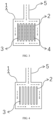
FIG. 1 shows a sectional diagram from a side view of the present disclosure. -
FIG. 2 shows a sectional diagram from a top view of the present disclosure. -
FIG. 3 shows a sectional diagram facing the gas outlet holes of the present disclosure. -
FIG. 4 shows a sectional diagram facing an air inlet of the present disclosure. -
FIG. 5 shows a schematic diagram of gas mixing of the present disclosure. -
FIG. 6 shows gas intake structure diagrams of a gas distribution cavity in embodiments of the present disclosure, whereFIG. 6(a) shows type I of a square type,FIG. 6(b) shows type II of a square type,FIG. 6(c) shows a C-shaped type,FIG. 6(d) shows a single-side type,FIG. 6(e) shows type I of an annular type, andFIG. 6(f) shows type II of an annular type gas intake. - In the
figures: 1 . housing, 2. external supporting structure, 3. gas pipe, 4. gas output hole, 5. gas intake mains. - To make the objectives, technical solutions and advantages of embodiments of the present disclosure more obvious, the technical solutions of the present disclosure will be clearly and completely described below in conjunction with the accompanying drawings in the embodiments of the present disclosure. Obviously, the described embodiments are some, rather than all of the embodiments of the present disclosure. Based on the embodiments of the present disclosure, all other embodiments acquired by those ordinary skilled in the art without making creative efforts fall within the scope of protection of the present disclosure.
- As shown in
FIGs. 1 to 4 , a gas-air mixing structure is disclosed in an embodiment of the present disclosure. The structure includes an external supportingstructure 2 arranged in ahousing 1 and a gas array pipe connected to the external supportingstructure 2. An air inlet is connected to one end of the housing, and a gas mixing channel is arranged between the gas array pipe and a mixed gas outlet (namely a gas outlet). The gas array pipe includes a plurality of gas pipes arranged in an array manner. Each of the plurality of gas pipes is provided with gas inlets and a plurality of gas output holes, and the plurality of gas output holes are provided on the leeward surfaces of the plurality of gas pipes. Gas output from the gas output holes is mixed with air to form a mixed gas. - The plurality of gas output holes are provided on the leeward surface of each of the plurality of gas pipes, and each of the plurality of gas output holes is circular hole or slit. The sectional area of each of the plurality of gas output holes is 1/20 to 1/2 of the sectional area of the gas pipe. The arrangement manner of the plurality of gas output holes is that several circular holes with a sectional area of 1/10 of the sectional area of the gas pipe are evenly distributed at the center of the leeward surface of the gas pipe with a spacing of 5 times the diameter of the circular hole.
- At least one row of gas pipes arranged in an array manner is arranged. As shown in
FIG. 5 , when the gas pipes are in multiple rows, two adjacent rows are arranged in a staggered manner. - The external supporting structure and the housing form a gas distribution cavity, and the housing of the gas distribution cavity is provided with a gas intake mains. One end of each gas pipe is connected to the gas distribution cavity, or both ends of each gas pipe are connected to the gas distribution cavity. Some embodiments are shown in
FIG. 6(a) to (f) , and the gas distribution cavity includes a gas intake structure of annular type, C-shaped type, hollow square type, and single-side type. Specifically,FIG. 6(a) shows a hollow square type, where all the gas pipes are parallel to the gas intake mains.FIG. 6(b) shows another hollow square type gas intake, where all the gas pipes are perpendicular to the gas intake mains. Gas is circulated in a hollow square shape in the hollow square type gas intake.FIG. 6(c) shows a C-shaped type with closed ends, where all gas pipes are parallel to the gas intake mains.FIG. 6(d) shows a single-side type, where all gas pipes are perpendicular to the gas intake mains, and both ends of the gas intake side are closed, that is, the input gas is circulated in all the gas pipes. The overall thinking of annular type gas intake structure shown inFIG. 6(e) and FIG. 6(f) is the same as that of the hollow square type gas intake structure shown inFIG. 6(a) and FIG. 6(b) , and the difference is that the circulation path is annular. - Finally, it should be noted that the above embodiments are only used to illustrate the technical solutions of the present invention, but not to limit them; although the present invention has been described in detail with reference to the foregoing embodiments, those ordinarily skilled in the art should understand that: the technical solutions described in the foregoing embodiments can still be modified, or some or all of the technical features thereof can be equivalently replaced; and these modifications or replacements do not make the essence of the corresponding technical solutions deviate from the scope of the technical solutions of the embodiments of the present invention.
Claims (9)
- A gas-air mixing structure, characterized by comprising an external supporting structure arranged in a housing and a gas array pipe connected thereto, wherein an air inlet is connected to one end of the housing, a gas mixing channel is arranged between the gas array pipe and a mixed gas outlet, the gas array pipe comprises a plurality of gas pipes arranged in an array manner, each of the plurality of gas pipes is provided with gas inlets and a plurality of gas output holes, and the plurality of gas output holes are provided on the leeward surface of each of the plurality of gas pipes.
- The gas-air mixing structure according to claim 1, characterized in that the plurality of gas output holes are provided on the leeward surface of each of the plurality of gas pipes, and each of the plurality of gas output holes is circular hole or slit.
- The gas-air mixing structure according to claim 1, characterized in that the sectional area of each of the plurality of gas output holes is 1/20 to 1/2 of the sectional area of the gas pipe.
- The gas-air mixing structure according to claim 1, characterized in that the arrangement manner of the plurality of gas output holes is that several circular holes with a sectional area of 1/10 of the sectional area of the gas pipe are evenly distributed at the center of the leeward surface of each of the gas pipe with a spacing of 5 times the diameter of the circular hole.
- The gas-air mixing structure according to claim 1, characterized in that at least one row of gas pipes arranged in an array manner is arranged.
- The gas-air mixing structure according to claim 5, characterized in that when the gas pipes are in multiple rows, two adjacent rows are arranged in a staggered manner.
- The gas-air mixing structure according to claim 1, characterized in that the external supporting structure and the housing form a gas distribution cavity, the housing of the gas distribution cavity is provided with a gas intake mains, one end of each gas pipe is connected to the gas distribution cavity, or both ends of each gas pipe are connected to the gas distribution cavity.
- The gas-air mixing structure according to claim 7, characterized in that the gas distribution cavity has a gas intake structure of annular type, C-shaped type, hollow square type, and single-side type.
- A burner, characterized by comprising the gas-air mixing structure according to any one of claims 1-8.
Applications Claiming Priority (3)
| Application Number | Priority Date | Filing Date | Title |
|---|---|---|---|
| CN202111396849.1A CN114034043A (en) | 2021-11-23 | 2021-11-23 | Gas and air gas mixing structure and combustor |
| CN202122880926.2U CN216346272U (en) | 2021-11-23 | 2021-11-23 | Gas and air gas mixing structure and combustor |
| PCT/CN2022/131636 WO2023093554A1 (en) | 2021-11-23 | 2022-11-14 | Gas-air mixing structure and burner |
Publications (2)
| Publication Number | Publication Date |
|---|---|
| EP4417867A1 true EP4417867A1 (en) | 2024-08-21 |
| EP4417867A4 EP4417867A4 (en) | 2025-03-05 |
Family
ID=86538831
Family Applications (1)
| Application Number | Title | Priority Date | Filing Date |
|---|---|---|---|
| EP22897637.9A Pending EP4417867A4 (en) | 2021-11-23 | 2022-11-14 | GAS-AIR MIXING STRUCTURE AND BURNER |
Country Status (6)
| Country | Link |
|---|---|
| US (1) | US20250020321A1 (en) |
| EP (1) | EP4417867A4 (en) |
| JP (1) | JP2024540646A (en) |
| KR (1) | KR20240110619A (en) |
| CA (1) | CA3238036A1 (en) |
| WO (1) | WO2023093554A1 (en) |
Family Cites Families (16)
| Publication number | Priority date | Publication date | Assignee | Title |
|---|---|---|---|---|
| NL290637A (en) * | 1963-03-07 | |||
| JPS5651955Y2 (en) * | 1978-06-30 | 1981-12-04 | ||
| JPS5626811Y2 (en) * | 1978-06-30 | 1981-06-25 | ||
| DE2965172D1 (en) * | 1979-02-03 | 1983-05-19 | Kromschroeder Ag G | Gas heated tunnel burner for raising the temperature in melting furnaces or crucibles |
| JP2863841B1 (en) * | 1998-01-08 | 1999-03-03 | 科学技術庁航空宇宙技術研究所長 | High load swivel burner array |
| JP4179761B2 (en) * | 2001-03-26 | 2008-11-12 | 大阪瓦斯株式会社 | Burner device and fluid heating device including the same |
| JP2002371917A (en) * | 2001-04-13 | 2002-12-26 | Mitsubishi Heavy Ind Ltd | Gas injection device for gas engine |
| US7874835B2 (en) * | 2008-03-27 | 2011-01-25 | Schwank Ltd. | Radiant tube heater and burner assembly for use therein |
| CN202350040U (en) * | 2011-11-10 | 2012-07-25 | 江门市卡迪慧亚金属制品有限公司 | Fence type constant-temperature combustor |
| CN105246382B (en) * | 2013-03-05 | 2017-12-12 | 烧烤用具有限责任公司 | Slim multiple-tubed burner for gas grill |
| CN207622007U (en) * | 2017-11-28 | 2018-07-17 | 广西富力永恒厨房设备有限公司 | A gas stove burner |
| CN108980829A (en) * | 2018-04-23 | 2018-12-11 | 上海钜荷热力技术有限公司 | A kind of star-like gas-air premixed device |
| CN214038414U (en) * | 2020-12-16 | 2021-08-24 | 四川铭能科技开发有限公司 | Air and gas rapid mixer |
| CN112963833B (en) * | 2021-02-24 | 2022-04-05 | 西安交通大学 | A kind of ammonia low nitrogen multi-stage swirl burner |
| CN114034043A (en) * | 2021-11-23 | 2022-02-11 | 中国科学院大连化学物理研究所 | Gas and air gas mixing structure and combustor |
| CN216346272U (en) * | 2021-11-23 | 2022-04-19 | 中国科学院大连化学物理研究所 | Gas and air gas mixing structure and combustor |
-
2022
- 2022-11-14 CA CA3238036A patent/CA3238036A1/en active Pending
- 2022-11-14 KR KR1020247019653A patent/KR20240110619A/en active Pending
- 2022-11-14 US US18/712,781 patent/US20250020321A1/en active Pending
- 2022-11-14 JP JP2024530510A patent/JP2024540646A/en active Pending
- 2022-11-14 EP EP22897637.9A patent/EP4417867A4/en active Pending
- 2022-11-14 WO PCT/CN2022/131636 patent/WO2023093554A1/en not_active Ceased
Also Published As
| Publication number | Publication date |
|---|---|
| US20250020321A1 (en) | 2025-01-16 |
| EP4417867A4 (en) | 2025-03-05 |
| JP2024540646A (en) | 2024-10-31 |
| CA3238036A1 (en) | 2023-06-01 |
| WO2023093554A1 (en) | 2023-06-01 |
| KR20240110619A (en) | 2024-07-15 |
Similar Documents
| Publication | Publication Date | Title |
|---|---|---|
| AU615989B2 (en) | Improvements in burners | |
| US3649211A (en) | Air augmented duct burner | |
| BRPI1001922A2 (en) | air burning apparatus and method | |
| CN114034043A (en) | Gas and air gas mixing structure and combustor | |
| CN216346272U (en) | Gas and air gas mixing structure and combustor | |
| CN116066855A (en) | Combustion chamber structure of a gas turbine with circumferentially dispersed main burner nozzles | |
| CN112762448A (en) | Low NO of coupling grading cyclone dispersion combustion technologyxGas burner | |
| US20250020321A1 (en) | Gas-air mixing structure and burner | |
| CN119042661A (en) | Staggered multi-point radial injection hydrogen fuel burner | |
| JPS5838686B2 (en) | Burner device for gaseous fuel | |
| CA2172203A1 (en) | Short flame xcl burner | |
| CN108954317B (en) | Negative pressure low NO for wall hanging stovexBurner with a burner head | |
| EP2825823A1 (en) | Gas turbine combustion system and method of flame stabilization in such a system | |
| WO2020140381A1 (en) | Multi-ejector tube type fire plate | |
| RU2832147C2 (en) | Gas-air mixing structure and burner | |
| CN217785205U (en) | Cyclone burner for simulating actual combustion | |
| CN211854001U (en) | Water-cooling full-premixing gas ultra-low nitrogen plane burner | |
| US1922348A (en) | Burner | |
| US20200309364A1 (en) | Burner and assembly of compact burners | |
| CN211119342U (en) | Bottom burner | |
| CN115539947B (en) | Premixing burner | |
| EP4019836A1 (en) | Shaped burner piece with internal flue gas recirculation | |
| US12066184B2 (en) | Low-NOx air heating swirl burner | |
| CN111780112B (en) | Injection mechanism for low-nitrogen combustor | |
| CN107726314A (en) | A kind of low nitrogen combustion apparatus |
Legal Events
| Date | Code | Title | Description |
|---|---|---|---|
| STAA | Information on the status of an ep patent application or granted ep patent |
Free format text: STATUS: THE INTERNATIONAL PUBLICATION HAS BEEN MADE |
|
| PUAI | Public reference made under article 153(3) epc to a published international application that has entered the european phase |
Free format text: ORIGINAL CODE: 0009012 |
|
| STAA | Information on the status of an ep patent application or granted ep patent |
Free format text: STATUS: REQUEST FOR EXAMINATION WAS MADE |
|
| 17P | Request for examination filed |
Effective date: 20240513 |
|
| AK | Designated contracting states |
Kind code of ref document: A1 Designated state(s): AL AT BE BG CH CY CZ DE DK EE ES FI FR GB GR HR HU IE IS IT LI LT LU LV MC ME MK MT NL NO PL PT RO RS SE SI SK SM TR |
|
| DAV | Request for validation of the european patent (deleted) | ||
| DAX | Request for extension of the european patent (deleted) | ||
| A4 | Supplementary search report drawn up and despatched |
Effective date: 20250204 |
|
| RIC1 | Information provided on ipc code assigned before grant |
Ipc: F23D 14/62 20060101ALI20250129BHEP Ipc: F23D 14/02 20060101AFI20250129BHEP |
|
| STAA | Information on the status of an ep patent application or granted ep patent |
Free format text: STATUS: EXAMINATION IS IN PROGRESS |
|
| 17Q | First examination report despatched |
Effective date: 20250820 |