EP4417839A1 - Gear - Google Patents
Gear Download PDFInfo
- Publication number
- EP4417839A1 EP4417839A1 EP23305191.1A EP23305191A EP4417839A1 EP 4417839 A1 EP4417839 A1 EP 4417839A1 EP 23305191 A EP23305191 A EP 23305191A EP 4417839 A1 EP4417839 A1 EP 4417839A1
- Authority
- EP
- European Patent Office
- Prior art keywords
- shaft
- tooth
- groove
- teeth
- retainer
- Prior art date
- Legal status (The legal status is an assumption and is not a legal conclusion. Google has not performed a legal analysis and makes no representation as to the accuracy of the status listed.)
- Pending
Links
Images


Classifications
-
- F—MECHANICAL ENGINEERING; LIGHTING; HEATING; WEAPONS; BLASTING
- F16—ENGINEERING ELEMENTS AND UNITS; GENERAL MEASURES FOR PRODUCING AND MAINTAINING EFFECTIVE FUNCTIONING OF MACHINES OR INSTALLATIONS; THERMAL INSULATION IN GENERAL
- F16H—GEARING
- F16H55/00—Elements with teeth or friction surfaces for conveying motion; Worms, pulleys or sheaves for gearing mechanisms
- F16H55/02—Toothed members; Worms
- F16H55/12—Toothed members; Worms with body or rim assembled out of detachable parts
-
- B—PERFORMING OPERATIONS; TRANSPORTING
- B23—MACHINE TOOLS; METAL-WORKING NOT OTHERWISE PROVIDED FOR
- B23P—METAL-WORKING NOT OTHERWISE PROVIDED FOR; COMBINED OPERATIONS; UNIVERSAL MACHINE TOOLS
- B23P11/00—Connecting or disconnecting metal parts or objects by metal-working techniques not otherwise provided for
- B23P11/02—Connecting or disconnecting metal parts or objects by metal-working techniques not otherwise provided for by first expanding and then shrinking or vice versa, e.g. by using pressure fluids; by making force fits
- B23P11/025—Connecting or disconnecting metal parts or objects by metal-working techniques not otherwise provided for by first expanding and then shrinking or vice versa, e.g. by using pressure fluids; by making force fits by using heat or cold
-
- F—MECHANICAL ENGINEERING; LIGHTING; HEATING; WEAPONS; BLASTING
- F16—ENGINEERING ELEMENTS AND UNITS; GENERAL MEASURES FOR PRODUCING AND MAINTAINING EFFECTIVE FUNCTIONING OF MACHINES OR INSTALLATIONS; THERMAL INSULATION IN GENERAL
- F16H—GEARING
- F16H55/00—Elements with teeth or friction surfaces for conveying motion; Worms, pulleys or sheaves for gearing mechanisms
- F16H55/02—Toothed members; Worms
- F16H55/06—Use of materials; Use of treatments of toothed members or worms to affect their intrinsic material properties
-
- F—MECHANICAL ENGINEERING; LIGHTING; HEATING; WEAPONS; BLASTING
- F16—ENGINEERING ELEMENTS AND UNITS; GENERAL MEASURES FOR PRODUCING AND MAINTAINING EFFECTIVE FUNCTIONING OF MACHINES OR INSTALLATIONS; THERMAL INSULATION IN GENERAL
- F16H—GEARING
- F16H55/00—Elements with teeth or friction surfaces for conveying motion; Worms, pulleys or sheaves for gearing mechanisms
- F16H55/02—Toothed members; Worms
- F16H55/17—Toothed wheels
-
- F—MECHANICAL ENGINEERING; LIGHTING; HEATING; WEAPONS; BLASTING
- F16—ENGINEERING ELEMENTS AND UNITS; GENERAL MEASURES FOR PRODUCING AND MAINTAINING EFFECTIVE FUNCTIONING OF MACHINES OR INSTALLATIONS; THERMAL INSULATION IN GENERAL
- F16H—GEARING
- F16H57/00—General details of gearing
- F16H57/02—Gearboxes; Mounting gearing therein
-
- B—PERFORMING OPERATIONS; TRANSPORTING
- B64—AIRCRAFT; AVIATION; COSMONAUTICS
- B64D—EQUIPMENT FOR FITTING IN OR TO AIRCRAFT; FLIGHT SUITS; PARACHUTES; ARRANGEMENT OR MOUNTING OF POWER PLANTS OR PROPULSION TRANSMISSIONS IN AIRCRAFT
- B64D35/00—Transmitting power from power plants to propellers or rotors; Arrangements of transmissions
-
- F—MECHANICAL ENGINEERING; LIGHTING; HEATING; WEAPONS; BLASTING
- F16—ENGINEERING ELEMENTS AND UNITS; GENERAL MEASURES FOR PRODUCING AND MAINTAINING EFFECTIVE FUNCTIONING OF MACHINES OR INSTALLATIONS; THERMAL INSULATION IN GENERAL
- F16H—GEARING
- F16H57/00—General details of gearing
- F16H57/02—Gearboxes; Mounting gearing therein
- F16H2057/02039—Gearboxes for particular applications
- F16H2057/02043—Gearboxes for particular applications for vehicle transmissions
Definitions
- This application relates to a method of manufacturing a gear, a gear, a gearbox, an aircraft power system and an aircraft.
- a method of manufacturing a gear comprising: providing a shaft; forming a groove into the shaft; and inserting a tooth into the groove such that the tooth is retained in the groove by an interference fit.
- the tooth may be made of a different material from the shaft. This may be particularly useful where the tooth is formed of a material with a maximum thickness less than a maximum dimension of the gear. Additionally, cost may be reduced, with the teeth formed of a more expensive material exhibiting improved mechanical properties and the shaft formed of a cheaper material.
- An interference fit is a simple and effective way to maintain the tooth in the groove.
- the method may comprise the shaft being at a higher temperature than the tooth while inserting the tooth into the groove.
- the method may comprise heating the shaft to a temperature T1 while inserting the tooth into the groove.
- T1 may be greater than 50°C. T1 may be greater than 60°C. T1 may be greater than 75°C. T1 may be greater than 90°C. T1 may be substantially than 100°C.
- the method may comprise cooling the tooth to a temperature T2 while inserting the tooth into the groove.
- T2 may be less than 10°C. T2 may be less than 0°C. T2 may be less than -10°C. T2 may be substantially -20°C.
- the method may comprise fixing a retainer to the shaft such that the tooth is retained in the groove by the retainer in addition to the interference fit.
- the method may comprise fixing first and second retainers to the shaft.
- the retainer may maintain an axial position of the tooth.
- the interference fit may maintain a radial position of the tooth.
- the interference fit may maintain a circumferential position of the tooth.
- the retainer may reduce sliding of the tooth in the groove.
- the retainer may be a sleeve.
- the retainer may surround the shaft.
- the retainer may be substantially cylindrical.
- the retainer may be formed of steel.
- the retainer may surround a tooth-free portion of the shaft.
- the tooth-free portion may be at an end of the shaft.
- the gear may comprise first and second retainers at opposing ends of the shaft.
- the method may comprise heating the retainer while providing the retainer around the tooth.
- the tooth may be formed of metallic glass.
- the shaft may be formed of steel.
- a gear comprising a shaft, the shaft comprising a groove; and a tooth received in the groove, wherein the tooth is retained in the groove by an interference fit.
- the gear may comprise a retainer fixed to the shaft, the retainer retaining the tooth in the groove in addition to the interference fit.
- the retainer may be a sleeve.
- the retainer may surround the shaft.
- the retainer may be substantially cylindrical.
- the retainer may be formed of steel.
- the retainer may maintain an axial position of the tooth.
- the interference fit may maintain a radial position of the tooth.
- the interference fit may maintain a circumferential position of the tooth.
- the retainer may reduce or prevent sliding of the tooth in the groove.
- the retainer may surround a tooth-free portion of the shaft.
- the tooth-free portion may be at an end of the shaft.
- the gear may comprise first and second retainers at opposing ends of the shaft.
- the tooth may be formed of metallic glass.
- the shaft may be formed of steel.
- a gearbox comprising the gear described above.
- an aircraft power system comprising the gearbox described above.
- the aircraft power system may be a propulsion system.
- the aircraft power system may be a secondary power system.
- the aircraft power system may be a control system.
- an aircraft comprising the aircraft power system described above.
- the method of the first aspect may comprise any of the functional steps described with respect to the second to fifth aspects.
- the gear of the second aspect may comprise any of the features described with respect to the method of the first aspect.
- the gearbox of the third aspect may comprise any of the features described with respect to the method of the first aspect and/or the gear of the second aspect.
- the aircraft power system of the fourth aspect may comprise any of the features described with respect to the method of the first aspect, the gear of the second aspect and/or the gearbox of the third aspect.
- the aircraft of the fifth aspect may comprise any of the features described with respect to the method of the first aspect, the gear of the second aspect, the gearbox of the third aspect and/or the aircraft power system of the fourth aspect.
- Fig. 1 shows a gear 10.
- the gear 10 comprises a shaft 12, teeth 14 and retainers 16a 16b.
- the shaft 12 is cylindrical.
- the shaft 12 is formed of stainless steel.
- the shaft 12 comprises grooves 18.
- the grooves 18 are formed in a radially outward facing surface 19 (defined with respect to an axis of the shaft 12) of the shaft 12.
- the grooves 18 extend in an axial direction (i.e. parallel to the axis of the shaft).
- the grooves 18 extend along a full length of the shaft 12.
- the grooves 14 are distributed circumferentially around the shaft 12.
- the teeth 14 are received in the grooves 18.
- the teeth 14 extend in the axial direction.
- the teeth 14 do not extend along the full length of the shaft 12.
- the teeth 14 do not extend to ends of the shaft 12, such that the shaft 12 comprises first and second tooth-free portions 20a 20b at the ends of the shaft 12.
- Each tooth 14 comprises an axially extending edge 22.
- Each tooth 14 is a separate component.
- the teeth 14 are separate components from the shaft 12.
- the teeth 14 are formed of a different material to the shaft 12.
- the teeth 14 are formed of a material with better mechanical properties (e.g. higher Young Modulus, high endurance, lower elastic deformation, higher hardness, lower corrosion susceptibility and/or lower friction coefficient) than the shaft 12.
- the teeth 14 are formed of an amorphous metallic alloy, which may also be referred to as a metallic glass.
- the amorphous metallic alloy has a random atomic distribution.
- the amorphous metallic alloys may only be able to form components up to a maximum thickness, which may be around 1 to 1.5 mm.
- each tooth 14 may have a greater width than the groove 18.
- the teeth 14 may therefore be in a compressed state in the grooves 18 to provide the interference fit.
- the interference fit maintains a radial and circumferential position of the teeth 14 in the grooves 18.
- the gear 10 comprises first and second retainers 16a 16b.
- the first retainer 16a covers the first tooth-free portion 20a.
- the second retainer 16b covers the second tooth-free portion 20b.
- the first and second retainers 16a 16b maintain an axial position of the teeth 14.
- the first retainer 16a abuts a first end of the teeth 14.
- the second retainer 16b abuts a second end of the teeth 14.
- the retainers 16a 16b are fixed to the shaft 12 by a press fit connection (not shown), which maintains an axial position of the retainers 16a 16b.
- the retainers 16a 16b are sleeves surrounding the shaft 12.
- the retainers 16a 16b are cylindrical.
- the retainers 16a 16b are formed of stainless steel.
- the gear 10 forms part of a gearbox (not shown), which in turn forms part of an aircraft power system (e.g. a propulsion system or a control system for moving a control surface) of an aircraft.
- the teeth 14 mesh with other component(s) of the gearbox to transmit mechanical power as the gear 10 rotates about its axis.
- a method 100 of manufacturing the above-described gear 10 comprises a shaft provision step 102, a groove forming step 104, a tooth insertion step 106 and a retainer attaching step 108.
- the shaft 12 is provided.
- the grooves 18 are formed in the shaft 12.
- the grooves 18 are formed in the radially outward facing surface 19 of the shaft 12.
- the grooves 18 are machined in the shaft 12.
- the teeth 14 are inserted into the grooves 18. While the teeth 14 are inserted into the grooves 18, the grooves 18 are heated. The teeth 14 are heated to a temperature T1, which in the present example is 100°C. While the teeth 14 are inserted into the grooves 18, the teeth 14 are cooled. The teeth 14 are cooled to a temperature T2, which in the present example is -20°C.
- T1 which in the present example is 100°C.
- T2 which in the present example is -20°C.
- first and second retainers 16a 16b are fixed to the shaft 12.
- the first tooth-free portion 20a of the shaft 12 is inserted into the first retainer 16a.
- the second tooth-free portion 20b of the shaft 12 is inserted into the second retainer 16b.
- the retainers 16a 16b may be heated relative to the shaft 12 when the retainers 16a 16b are fixed to the shaft 12.
- a tooth machining step (not shown) follows the steps described above.
- the teeth 14 are machined to ensure that they are aligned with each other.
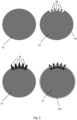
- Fig. 2 shows grooves 18 and teeth 14 around only a portion of the circumference of the shaft 12 for clarity, the grooves 18 and teeth 14 are distributed around the full circumference of the shaft 12 as shown in Fig. 1 .
Landscapes
- Engineering & Computer Science (AREA)
- General Engineering & Computer Science (AREA)
- Mechanical Engineering (AREA)
- Physics & Mathematics (AREA)
- Electromagnetism (AREA)
- Thermal Sciences (AREA)
- Gears, Cams (AREA)
- Gear Processing (AREA)
Abstract
A method of manufacturing a gear, the method comprising: providing a shaft; forming a groove into the shaft; and inserting a tooth into the groove such that the tooth is retained in the groove by an interference fit.
Description
- This application relates to a method of manufacturing a gear, a gear, a gearbox, an aircraft power system and an aircraft.
- It is desirable to improve the mechanical properties of materials for gears such that their size and weight can be reduced, particularly in gearboxes for aircraft. Materials with improved mechanical properties often have high associated costs and manufacturability issues.
- According to a first aspect there is provided a method of manufacturing a gear, the method comprising: providing a shaft; forming a groove into the shaft; and inserting a tooth into the groove such that the tooth is retained in the groove by an interference fit.
- By connecting a tooth to a separate shaft component in this way, the tooth may be made of a different material from the shaft. This may be particularly useful where the tooth is formed of a material with a maximum thickness less than a maximum dimension of the gear. Additionally, cost may be reduced, with the teeth formed of a more expensive material exhibiting improved mechanical properties and the shaft formed of a cheaper material. An interference fit is a simple and effective way to maintain the tooth in the groove.
- The method may comprise the shaft being at a higher temperature than the tooth while inserting the tooth into the groove.
- The method may comprise heating the shaft to a temperature T1 while inserting the tooth into the groove.
- T1 may be greater than 50°C. T1 may be greater than 60°C. T1 may be greater than 75°C. T1 may be greater than 90°C. T1 may be substantially than 100°C.
- The method may comprise cooling the tooth to a temperature T2 while inserting the tooth into the groove.
- T2 may be less than 10°C. T2 may be less than 0°C. T2 may be less than -10°C. T2 may be substantially -20°C.
- The method may comprise fixing a retainer to the shaft such that the tooth is retained in the groove by the retainer in addition to the interference fit. The method may comprise fixing first and second retainers to the shaft.
- The retainer may maintain an axial position of the tooth. The interference fit may maintain a radial position of the tooth. The interference fit may maintain a circumferential position of the tooth. The retainer may reduce sliding of the tooth in the groove.
- The retainer may be a sleeve. The retainer may surround the shaft. The retainer may be substantially cylindrical. The retainer may be formed of steel.
- The retainer may surround a tooth-free portion of the shaft. The tooth-free portion may be at an end of the shaft. The gear may comprise first and second retainers at opposing ends of the shaft.
- The method may comprise heating the retainer while providing the retainer around the tooth.
- The tooth may be formed of metallic glass. The shaft may be formed of steel.
- According to a second aspect there is provided a gear comprising a shaft, the shaft comprising a groove; and a tooth received in the groove, wherein the tooth is retained in the groove by an interference fit.
- The gear may comprise a retainer fixed to the shaft, the retainer retaining the tooth in the groove in addition to the interference fit.
- The retainer may be a sleeve. The retainer may surround the shaft. The retainer may be substantially cylindrical. The retainer may be formed of steel.
- The retainer may maintain an axial position of the tooth. The interference fit may maintain a radial position of the tooth. The interference fit may maintain a circumferential position of the tooth. The retainer may reduce or prevent sliding of the tooth in the groove.
- The retainer may surround a tooth-free portion of the shaft. The tooth-free portion may be at an end of the shaft. The gear may comprise first and second retainers at opposing ends of the shaft.
- The tooth may be formed of metallic glass. The shaft may be formed of steel.
- According to a third aspect there is provided a gearbox comprising the gear described above.
- According to a fourth aspect there is provided an aircraft power system comprising the gearbox described above. The aircraft power system may be a propulsion system. The aircraft power system may be a secondary power system. The aircraft power system may be a control system.
- According to a fifth aspect there is provided an aircraft comprising the aircraft power system described above.
- The method of the first aspect may comprise any of the functional steps described with respect to the second to fifth aspects. The gear of the second aspect may comprise any of the features described with respect to the method of the first aspect. The gearbox of the third aspect may comprise any of the features described with respect to the method of the first aspect and/or the gear of the second aspect. The aircraft power system of the fourth aspect may comprise any of the features described with respect to the method of the first aspect, the gear of the second aspect and/or the gearbox of the third aspect. The aircraft of the fifth aspect may comprise any of the features described with respect to the method of the first aspect, the gear of the second aspect, the gearbox of the third aspect and/or the aircraft power system of the fourth aspect.
- Various examples will now be described with reference to the accompanying drawings in which:
-
Fig. 1 shows a perspective view of a gear -
Fig. 2 shows an end view of the gear at various stages during a method of manufacturing the gear; -
Fig. 3 shows a flow diagram of a method of manufacturing the gear. -
Fig. 1 shows agear 10. Thegear 10 comprises ashaft 12,teeth 14 andretainers 16a - The
shaft 12 is cylindrical. Theshaft 12 is formed of stainless steel. Theshaft 12 comprisesgrooves 18. Thegrooves 18 are formed in a radially outward facing surface 19 (defined with respect to an axis of the shaft 12) of theshaft 12. Thegrooves 18 extend in an axial direction (i.e. parallel to the axis of the shaft). Thegrooves 18 extend along a full length of theshaft 12. Thegrooves 14 are distributed circumferentially around theshaft 12. - The
teeth 14 are received in thegrooves 18. Theteeth 14 extend in the axial direction. Theteeth 14 do not extend along the full length of theshaft 12. Theteeth 14 do not extend to ends of theshaft 12, such that theshaft 12 comprises first and second tooth-free portions 20ashaft 12. Eachtooth 14 comprises anaxially extending edge 22. - Each
tooth 14 is a separate component. Theteeth 14 are separate components from theshaft 12. Theteeth 14 are formed of a different material to theshaft 12. Theteeth 14 are formed of a material with better mechanical properties (e.g. higher Young Modulus, high endurance, lower elastic deformation, higher hardness, lower corrosion susceptibility and/or lower friction coefficient) than theshaft 12. - The
teeth 14 are formed of an amorphous metallic alloy, which may also be referred to as a metallic glass. The amorphous metallic alloy has a random atomic distribution. The amorphous metallic alloys may only be able to form components up to a maximum thickness, which may be around 1 to 1.5 mm. - The
teeth 14 are maintained in thegrooves 18 by an interference fit. In an unstressed state, eachtooth 14 may have a greater width than thegroove 18. Theteeth 14 may therefore be in a compressed state in thegrooves 18 to provide the interference fit. The interference fit maintains a radial and circumferential position of theteeth 14 in thegrooves 18. - The
gear 10 comprises first andsecond retainers 16afirst retainer 16a covers the first tooth-free portion 20a. Thesecond retainer 16b covers the second tooth-free portion 20b. The first andsecond retainers 16ateeth 14. Thefirst retainer 16a abuts a first end of theteeth 14. Thesecond retainer 16b abuts a second end of theteeth 14. Theretainers 16ashaft 12 by a press fit connection (not shown), which maintains an axial position of theretainers 16a - The
retainers 16ashaft 12. Theretainers 16aretainers 16a - In use, the
gear 10 forms part of a gearbox (not shown), which in turn forms part of an aircraft power system (e.g. a propulsion system or a control system for moving a control surface) of an aircraft. Theteeth 14 mesh with other component(s) of the gearbox to transmit mechanical power as thegear 10 rotates about its axis. - Referring to
Fig. 2 and3 , amethod 100 of manufacturing the above-describedgear 10 comprises ashaft provision step 102, agroove forming step 104, atooth insertion step 106 and aretainer attaching step 108. - In the
shaft provision step 102, theshaft 12 is provided. - In the
groove forming step 104, thegrooves 18 are formed in theshaft 12. Thegrooves 18 are formed in the radially outward facingsurface 19 of theshaft 12. Thegrooves 18 are machined in theshaft 12. - In the
tooth insertion step 106, theteeth 14 are inserted into thegrooves 18. While theteeth 14 are inserted into thegrooves 18, thegrooves 18 are heated. Theteeth 14 are heated to a temperature T1, which in the present example is 100°C. While theteeth 14 are inserted into thegrooves 18, theteeth 14 are cooled. Theteeth 14 are cooled to a temperature T2, which in the present example is -20°C. By heating thegrooves 18 relative to theteeth 14, thegrooves 18 expand relative to theteeth 14, which means thatlarger teeth 14 can be inserted intosmaller grooves 18. This improves the interference fit. In some examples, theshaft 12 may be heated with theteeth 14 remaining at ambient conditions or theteeth 14 may be cooled with theshaft 12 remaining at ambient conditions. In others examples, the method of manufacturing may be simplified by inserting theteeth 14 without heating and/or cooling. - In the
retainer attaching step 108, first andsecond retainers 16ashaft 12. The first tooth-free portion 20a of theshaft 12 is inserted into thefirst retainer 16a. The second tooth-free portion 20b of theshaft 12 is inserted into thesecond retainer 16b. Theretainers 16ashaft 12 when theretainers 16ashaft 12. - In some examples, a tooth machining step (not shown) follows the steps described above. In the tooth machining step, the
teeth 14 are machined to ensure that they are aligned with each other. - It will be understood that while
Fig. 2 showsgrooves 18 andteeth 14 around only a portion of the circumference of theshaft 12 for clarity, thegrooves 18 andteeth 14 are distributed around the full circumference of theshaft 12 as shown inFig. 1 . - Various aspects of the apparatus disclosed in the various embodiments may be used alone, in combination, or in a variety of arrangements not specifically discussed in the embodiments described in the foregoing and this disclosure is therefore not limited in its application to the details and arrangement of components set forth in the foregoing description or illustrated in the drawings. For example, aspects described in one embodiment may be combined in any manner with aspects described in other embodiments. Although particular embodiments have been shown and described, it will be obvious to those skilled in the art that changes and modifications may be made without departing from this invention in its broader aspects. The scope of the following claims should not be limited by the embodiments set forth in the examples, but should be given the broadest reasonable interpretation consistent with the description as a whole.
Claims (15)
- A method of manufacturing a gear, the method comprising:providing a shaft;forming a groove into the shaft; andinserting a tooth into the groove such that the tooth is retained in the groove by an interference fit.
- A method according to claim 1 and comprising heating the shaft to a temperature T1 while inserting the tooth into the groove.
- A method according to claim 2, wherein T1 is greater than 75°C, optionally substantially 100°C.
- A method according to any preceding claim and comprising cooling the tooth to a temperature T2 while inserting the tooth into the groove.
- A method according to claim 4, wherein T2 is less than 0°C, optionally substantially -20°C.
- A method according to any preceding claim and comprising fixing a retainer to the shaft such that the tooth is retained in the groove by the retainer in addition to the interference fit.
- A method according to claim 6, wherein the retainer is a sleeve.
- A method according to any preceding claim and comprising forming a plurality of grooves around a circumference of the shaft and inserting a plurality teeth into the grooves such that the teeth are retained in the grooves by the interference fit.
- A method according to any of the preceding claims, wherein the tooth is formed of a metallic glass.
- A gear comprising:a shaft, the shaft comprising a groove; anda tooth received in the groove, wherein the tooth is retained in the groove by an interference fit.
- A gearbox comprising the gear of claim 10.
- An aircraft power system comprising the gearbox of claim 11.
- An aircraft power system according to claim 12, wherein the aircraft power system is a propulsion system.
- An aircraft power system according to claim 12, wherein the aircraft power system is a control system.
- An aircraft comprising the aircraft power system of any of claims 12 to 14.
Priority Applications (3)
| Application Number | Priority Date | Filing Date | Title |
|---|---|---|---|
| EP23305191.1A EP4417839A1 (en) | 2023-02-14 | 2023-02-14 | Gear |
| CA3220772A CA3220772A1 (en) | 2023-02-14 | 2023-11-22 | Gear |
| US18/434,000 US20240269785A1 (en) | 2023-02-14 | 2024-02-06 | Gear |
Applications Claiming Priority (1)
| Application Number | Priority Date | Filing Date | Title |
|---|---|---|---|
| EP23305191.1A EP4417839A1 (en) | 2023-02-14 | 2023-02-14 | Gear |
Publications (1)
| Publication Number | Publication Date |
|---|---|
| EP4417839A1 true EP4417839A1 (en) | 2024-08-21 |
Family
ID=86052476
Family Applications (1)
| Application Number | Title | Priority Date | Filing Date |
|---|---|---|---|
| EP23305191.1A Pending EP4417839A1 (en) | 2023-02-14 | 2023-02-14 | Gear |
Country Status (3)
| Country | Link |
|---|---|
| US (1) | US20240269785A1 (en) |
| EP (1) | EP4417839A1 (en) |
| CA (1) | CA3220772A1 (en) |
Citations (7)
| Publication number | Priority date | Publication date | Assignee | Title |
|---|---|---|---|---|
| US441460A (en) * | 1890-11-25 | Gear-wheel | ||
| US3183734A (en) * | 1961-06-10 | 1965-05-18 | Sedis Transmissions Mec | Toothed wheel |
| US5203861A (en) * | 1991-12-18 | 1993-04-20 | Irwin Guy L | Plastic sprocket wheel with replaceable teeth |
| WO2006010602A2 (en) * | 2004-07-27 | 2006-02-02 | Fraunhofer-Gesellschaft zur Förderung der angewandten Forschung e.V. | Assembled gearwheel |
| CN103671824A (en) * | 2014-01-16 | 2014-03-26 | 苏州优金金属成型科技有限公司 | Novel gear |
| CN104565288A (en) * | 2014-11-28 | 2015-04-29 | 盐城工学院 | Detachable vibration reduction gear |
| DE102018206951A1 (en) * | 2018-05-04 | 2019-11-07 | Zf Friedrichshafen Ag | Multi-part gear |
Family Cites Families (10)
| Publication number | Priority date | Publication date | Assignee | Title |
|---|---|---|---|---|
| US4070920A (en) * | 1976-12-09 | 1978-01-31 | The Horsburgh And Scott Company | Composite gear having carburized teeth and method of making same |
| US9211583B2 (en) * | 2008-09-26 | 2015-12-15 | Borgwarner Inc. | Sleeved sprocket teeth |
| JP5522105B2 (en) * | 2011-03-31 | 2014-06-18 | アイシン・エィ・ダブリュ株式会社 | Steel gear and manufacturing method thereof |
| US8863924B2 (en) * | 2011-10-24 | 2014-10-21 | Bell Helicopter Textron Inc. | Hybrid overrunning clutch assembly and method of making same |
| US9328813B2 (en) * | 2013-02-11 | 2016-05-03 | California Institute Of Technology | Systems and methods for implementing bulk metallic glass-based strain wave gears and strain wave gear components |
| JP2016509180A (en) * | 2013-03-01 | 2016-03-24 | ボーグワーナー インコーポレーテッド | Sprocket technology to reduce noise, vibration and harmonics |
| US20150196980A1 (en) * | 2014-01-15 | 2015-07-16 | Shivam Autotech Ltd. | Method of manufacturing gear with teeth involving forging |
| US9724748B2 (en) * | 2014-08-11 | 2017-08-08 | Arvinmeritor Technology, Llc | System and method of making a forged part |
| JP6660752B2 (en) * | 2016-02-04 | 2020-03-11 | 高周波熱錬株式会社 | Quenching device |
| CN118080808A (en) * | 2023-12-26 | 2024-05-28 | 黄石市高潮工矿机械有限公司 | Machining length-adjustable nodular cast iron pipe die |
-
2023
- 2023-02-14 EP EP23305191.1A patent/EP4417839A1/en active Pending
- 2023-11-22 CA CA3220772A patent/CA3220772A1/en active Pending
-
2024
- 2024-02-06 US US18/434,000 patent/US20240269785A1/en active Pending
Patent Citations (7)
| Publication number | Priority date | Publication date | Assignee | Title |
|---|---|---|---|---|
| US441460A (en) * | 1890-11-25 | Gear-wheel | ||
| US3183734A (en) * | 1961-06-10 | 1965-05-18 | Sedis Transmissions Mec | Toothed wheel |
| US5203861A (en) * | 1991-12-18 | 1993-04-20 | Irwin Guy L | Plastic sprocket wheel with replaceable teeth |
| WO2006010602A2 (en) * | 2004-07-27 | 2006-02-02 | Fraunhofer-Gesellschaft zur Förderung der angewandten Forschung e.V. | Assembled gearwheel |
| CN103671824A (en) * | 2014-01-16 | 2014-03-26 | 苏州优金金属成型科技有限公司 | Novel gear |
| CN104565288A (en) * | 2014-11-28 | 2015-04-29 | 盐城工学院 | Detachable vibration reduction gear |
| DE102018206951A1 (en) * | 2018-05-04 | 2019-11-07 | Zf Friedrichshafen Ag | Multi-part gear |
Also Published As
| Publication number | Publication date |
|---|---|
| US20240269785A1 (en) | 2024-08-15 |
| CA3220772A1 (en) | 2025-04-30 |
Similar Documents
| Publication | Publication Date | Title |
|---|---|---|
| US11085509B2 (en) | Bending meshing type gear device | |
| US20170321790A1 (en) | Flex spline actuator | |
| US8944696B2 (en) | Cage for radial roller bearing | |
| EP1980762A2 (en) | Hydrodynamic fluid film bearing | |
| US8628251B2 (en) | Needle bearing | |
| US20050196089A1 (en) | Roller bearing | |
| US8690445B2 (en) | Rolling bearing arrangement | |
| JP2006144839A (en) | Roller bearing | |
| EP1058773A1 (en) | Method and apparatus for mounting a bearing | |
| JP2016501352A (en) | Torque limit tolerance ring | |
| US11035412B2 (en) | Bearing assembly and method of installation | |
| US20100154628A1 (en) | Piston pin device and method of making the same | |
| JP3340807B2 (en) | Roller bearing | |
| US20240269785A1 (en) | Gear | |
| US9927021B1 (en) | Planet carrier for a planetary gear set | |
| US20050274585A1 (en) | Freewheeling clutch | |
| DE102009056615A1 (en) | Balancing element for use as counter bearing in roller bearing e.g. angular ball bearing, of differential transmission of motor vehicle, has locking unit for mechanical locking of balancing element at bearing component of roller bearing | |
| JP2005233322A (en) | Roller bearing and assembling method thereof | |
| EP2963306A1 (en) | Preliminary holder for radial needle bearing | |
| EP3040569B1 (en) | Method for manufacturing shell-type needle bearing, and manufacturing jig used in manufacture of same | |
| EP2068021A2 (en) | Shaft apparatus with bearing | |
| DE102013004499A1 (en) | storage system | |
| JP6568119B2 (en) | Retainer for inner and outer shafts | |
| JP5982753B2 (en) | Tapered roller bearing assembly method | |
| BR102024001255A2 (en) | METHOD OF MANUFACTURING A GEAR, GEAR, GEARBOX, AIRCRAFT POWER SYSTEM, AND, AIRCRAFT |
Legal Events
| Date | Code | Title | Description |
|---|---|---|---|
| PUAI | Public reference made under article 153(3) epc to a published international application that has entered the european phase |
Free format text: ORIGINAL CODE: 0009012 |
|
| STAA | Information on the status of an ep patent application or granted ep patent |
Free format text: STATUS: THE APPLICATION HAS BEEN PUBLISHED |
|
| AK | Designated contracting states |
Kind code of ref document: A1 Designated state(s): AL AT BE BG CH CY CZ DE DK EE ES FI FR GB GR HR HU IE IS IT LI LT LU LV MC ME MK MT NL NO PL PT RO RS SE SI SK SM TR |
|
| STAA | Information on the status of an ep patent application or granted ep patent |
Free format text: STATUS: REQUEST FOR EXAMINATION WAS MADE |
|
| 17P | Request for examination filed |
Effective date: 20250218 |