EP4417788A1 - Gas turbine engine blade and method of sizing a damper for a gas turbine engine blade - Google Patents
Gas turbine engine blade and method of sizing a damper for a gas turbine engine blade Download PDFInfo
- Publication number
- EP4417788A1 EP4417788A1 EP24156941.7A EP24156941A EP4417788A1 EP 4417788 A1 EP4417788 A1 EP 4417788A1 EP 24156941 A EP24156941 A EP 24156941A EP 4417788 A1 EP4417788 A1 EP 4417788A1
- Authority
- EP
- European Patent Office
- Prior art keywords
- damper
- blade
- gas turbine
- platform
- turbine engine
- Prior art date
- Legal status (The legal status is an assumption and is not a legal conclusion. Google has not performed a legal analysis and makes no representation as to the accuracy of the status listed.)
- Pending
Links
- 238000000034 method Methods 0.000 title claims abstract description 21
- 238000004513 sizing Methods 0.000 title claims abstract description 6
- 239000007789 gas Substances 0.000 claims description 21
- -1 rare earth silicates Chemical class 0.000 claims description 16
- 239000000919 ceramic Substances 0.000 claims description 13
- XUIMIQQOPSSXEZ-UHFFFAOYSA-N Silicon Chemical compound [Si] XUIMIQQOPSSXEZ-UHFFFAOYSA-N 0.000 claims description 11
- 229910052710 silicon Inorganic materials 0.000 claims description 11
- 239000010703 silicon Substances 0.000 claims description 11
- 229910052581 Si3N4 Inorganic materials 0.000 claims description 10
- 238000003754 machining Methods 0.000 claims description 10
- HQVNEWCFYHHQES-UHFFFAOYSA-N silicon nitride Chemical compound N12[Si]34N5[Si]62N3[Si]51N64 HQVNEWCFYHHQES-UHFFFAOYSA-N 0.000 claims description 10
- 239000011153 ceramic matrix composite Substances 0.000 claims description 9
- 238000000151 deposition Methods 0.000 claims description 9
- GWEVSGVZZGPLCZ-UHFFFAOYSA-N Titan oxide Chemical compound O=[Ti]=O GWEVSGVZZGPLCZ-UHFFFAOYSA-N 0.000 claims description 8
- 229910000323 aluminium silicate Inorganic materials 0.000 claims description 8
- RUDFQVOCFDJEEF-UHFFFAOYSA-N oxygen(2-);yttrium(3+) Chemical class [O-2].[O-2].[O-2].[Y+3].[Y+3] RUDFQVOCFDJEEF-UHFFFAOYSA-N 0.000 claims description 8
- 229910010271 silicon carbide Inorganic materials 0.000 claims description 8
- 229910002087 alumina-stabilized zirconia Inorganic materials 0.000 claims description 7
- KZHJGOXRZJKJNY-UHFFFAOYSA-N dioxosilane;oxo(oxoalumanyloxy)alumane Chemical compound O=[Si]=O.O=[Si]=O.O=[Al]O[Al]=O.O=[Al]O[Al]=O.O=[Al]O[Al]=O KZHJGOXRZJKJNY-UHFFFAOYSA-N 0.000 claims description 7
- 229910000167 hafnon Inorganic materials 0.000 claims description 7
- 229910052863 mullite Inorganic materials 0.000 claims description 7
- 229910052845 zircon Inorganic materials 0.000 claims description 7
- GFQYVLUOOAAOGM-UHFFFAOYSA-N zirconium(iv) silicate Chemical compound [Zr+4].[O-][Si]([O-])([O-])[O-] GFQYVLUOOAAOGM-UHFFFAOYSA-N 0.000 claims description 7
- 238000005229 chemical vapour deposition Methods 0.000 claims description 6
- ILCYGSITMBHYNK-UHFFFAOYSA-N [Si]=O.[Hf] Chemical class [Si]=O.[Hf] ILCYGSITMBHYNK-UHFFFAOYSA-N 0.000 claims description 4
- IJBYNGRZBZDSDK-UHFFFAOYSA-N barium magnesium Chemical compound [Mg].[Ba] IJBYNGRZBZDSDK-UHFFFAOYSA-N 0.000 claims description 4
- QDOXWKRWXJOMAK-UHFFFAOYSA-N dichromium trioxide Chemical compound O=[Cr]O[Cr]=O QDOXWKRWXJOMAK-UHFFFAOYSA-N 0.000 claims description 4
- WIHZLLGSGQNAGK-UHFFFAOYSA-N hafnium(4+);oxygen(2-) Chemical class [O-2].[O-2].[Hf+4] WIHZLLGSGQNAGK-UHFFFAOYSA-N 0.000 claims description 4
- RVTZCBVAJQQJTK-UHFFFAOYSA-N oxygen(2-);zirconium(4+) Chemical class [O-2].[O-2].[Zr+4] RVTZCBVAJQQJTK-UHFFFAOYSA-N 0.000 claims description 4
- 229910052761 rare earth metal Inorganic materials 0.000 claims description 4
- 150000004760 silicates Chemical class 0.000 claims description 4
- LIVNPJMFVYWSIS-UHFFFAOYSA-N silicon monoxide Chemical class [Si-]#[O+] LIVNPJMFVYWSIS-UHFFFAOYSA-N 0.000 claims description 4
- 229910052814 silicon oxide Inorganic materials 0.000 claims description 4
- 229910001233 yttria-stabilized zirconia Inorganic materials 0.000 claims description 4
- 229910001928 zirconium oxide Inorganic materials 0.000 claims description 4
- 230000008021 deposition Effects 0.000 claims description 3
- 238000010894 electron beam technology Methods 0.000 claims description 3
- 238000000227 grinding Methods 0.000 claims description 3
- 238000003801 milling Methods 0.000 claims description 3
- 238000005289 physical deposition Methods 0.000 claims description 3
- 238000005240 physical vapour deposition Methods 0.000 claims description 3
- 238000007581 slurry coating method Methods 0.000 claims description 3
- 239000007921 spray Substances 0.000 claims description 3
- XLYOFNOQVPJJNP-UHFFFAOYSA-N water Substances O XLYOFNOQVPJJNP-UHFFFAOYSA-N 0.000 claims description 3
- 239000000835 fiber Substances 0.000 description 9
- 229920002134 Carboxymethyl cellulose Polymers 0.000 description 7
- 235000010948 carboxy methyl cellulose Nutrition 0.000 description 7
- 229920006184 cellulose methylcellulose Polymers 0.000 description 7
- 238000012710 chemistry, manufacturing and control Methods 0.000 description 7
- 239000000463 material Substances 0.000 description 7
- HBMJWWWQQXIZIP-UHFFFAOYSA-N silicon carbide Chemical compound [Si+]#[C-] HBMJWWWQQXIZIP-UHFFFAOYSA-N 0.000 description 7
- 239000000446 fuel Substances 0.000 description 5
- 239000011159 matrix material Substances 0.000 description 4
- 230000008901 benefit Effects 0.000 description 3
- 238000013016 damping Methods 0.000 description 3
- 230000009467 reduction Effects 0.000 description 3
- 230000002787 reinforcement Effects 0.000 description 3
- 238000002485 combustion reaction Methods 0.000 description 2
- 239000011156 metal matrix composite Substances 0.000 description 2
- 230000003068 static effect Effects 0.000 description 2
- 230000006978 adaptation Effects 0.000 description 1
- 230000002411 adverse Effects 0.000 description 1
- 238000013459 approach Methods 0.000 description 1
- 230000009286 beneficial effect Effects 0.000 description 1
- 230000015556 catabolic process Effects 0.000 description 1
- 229910010293 ceramic material Inorganic materials 0.000 description 1
- 230000008859 change Effects 0.000 description 1
- 239000011248 coating agent Substances 0.000 description 1
- 238000000576 coating method Methods 0.000 description 1
- 238000004891 communication Methods 0.000 description 1
- 239000002131 composite material Substances 0.000 description 1
- 230000006835 compression Effects 0.000 description 1
- 238000007906 compression Methods 0.000 description 1
- 238000012937 correction Methods 0.000 description 1
- 238000006731 degradation reaction Methods 0.000 description 1
- 238000005137 deposition process Methods 0.000 description 1
- 230000000694 effects Effects 0.000 description 1
- 230000007613 environmental effect Effects 0.000 description 1
- 238000012804 iterative process Methods 0.000 description 1
- 238000004519 manufacturing process Methods 0.000 description 1
- 230000007246 mechanism Effects 0.000 description 1
- 238000012986 modification Methods 0.000 description 1
- 230000004048 modification Effects 0.000 description 1
- 239000011160 polymer matrix composite Substances 0.000 description 1
- 229920013657 polymer matrix composite Polymers 0.000 description 1
- 230000008569 process Effects 0.000 description 1
- 230000004044 response Effects 0.000 description 1
- 238000009420 retrofitting Methods 0.000 description 1
- 230000007704 transition Effects 0.000 description 1
Images
Classifications
-
- F—MECHANICAL ENGINEERING; LIGHTING; HEATING; WEAPONS; BLASTING
- F01—MACHINES OR ENGINES IN GENERAL; ENGINE PLANTS IN GENERAL; STEAM ENGINES
- F01D—NON-POSITIVE DISPLACEMENT MACHINES OR ENGINES, e.g. STEAM TURBINES
- F01D5/00—Blades; Blade-carrying members; Heating, heat-insulating, cooling or antivibration means on the blades or the members
- F01D5/12—Blades
- F01D5/26—Antivibration means not restricted to blade form or construction or to blade-to-blade connections or to the use of particular materials
-
- F—MECHANICAL ENGINEERING; LIGHTING; HEATING; WEAPONS; BLASTING
- F01—MACHINES OR ENGINES IN GENERAL; ENGINE PLANTS IN GENERAL; STEAM ENGINES
- F01D—NON-POSITIVE DISPLACEMENT MACHINES OR ENGINES, e.g. STEAM TURBINES
- F01D5/00—Blades; Blade-carrying members; Heating, heat-insulating, cooling or antivibration means on the blades or the members
- F01D5/02—Blade-carrying members, e.g. rotors
- F01D5/027—Arrangements for balancing
-
- F—MECHANICAL ENGINEERING; LIGHTING; HEATING; WEAPONS; BLASTING
- F01—MACHINES OR ENGINES IN GENERAL; ENGINE PLANTS IN GENERAL; STEAM ENGINES
- F01D—NON-POSITIVE DISPLACEMENT MACHINES OR ENGINES, e.g. STEAM TURBINES
- F01D5/00—Blades; Blade-carrying members; Heating, heat-insulating, cooling or antivibration means on the blades or the members
- F01D5/12—Blades
- F01D5/28—Selecting particular materials; Particular measures relating thereto; Measures against erosion or corrosion
- F01D5/282—Selecting composite materials, e.g. blades with reinforcing filaments
-
- F—MECHANICAL ENGINEERING; LIGHTING; HEATING; WEAPONS; BLASTING
- F01—MACHINES OR ENGINES IN GENERAL; ENGINE PLANTS IN GENERAL; STEAM ENGINES
- F01D—NON-POSITIVE DISPLACEMENT MACHINES OR ENGINES, e.g. STEAM TURBINES
- F01D5/00—Blades; Blade-carrying members; Heating, heat-insulating, cooling or antivibration means on the blades or the members
- F01D5/12—Blades
- F01D5/28—Selecting particular materials; Particular measures relating thereto; Measures against erosion or corrosion
- F01D5/284—Selection of ceramic materials
-
- F—MECHANICAL ENGINEERING; LIGHTING; HEATING; WEAPONS; BLASTING
- F01—MACHINES OR ENGINES IN GENERAL; ENGINE PLANTS IN GENERAL; STEAM ENGINES
- F01D—NON-POSITIVE DISPLACEMENT MACHINES OR ENGINES, e.g. STEAM TURBINES
- F01D5/00—Blades; Blade-carrying members; Heating, heat-insulating, cooling or antivibration means on the blades or the members
- F01D5/12—Blades
- F01D5/14—Form or construction
- F01D5/16—Form or construction for counteracting blade vibration
-
- F—MECHANICAL ENGINEERING; LIGHTING; HEATING; WEAPONS; BLASTING
- F05—INDEXING SCHEMES RELATING TO ENGINES OR PUMPS IN VARIOUS SUBCLASSES OF CLASSES F01-F04
- F05D—INDEXING SCHEME FOR ASPECTS RELATING TO NON-POSITIVE-DISPLACEMENT MACHINES OR ENGINES, GAS-TURBINES OR JET-PROPULSION PLANTS
- F05D2220/00—Application
- F05D2220/30—Application in turbines
- F05D2220/32—Application in turbines in gas turbines
-
- F—MECHANICAL ENGINEERING; LIGHTING; HEATING; WEAPONS; BLASTING
- F05—INDEXING SCHEMES RELATING TO ENGINES OR PUMPS IN VARIOUS SUBCLASSES OF CLASSES F01-F04
- F05D—INDEXING SCHEME FOR ASPECTS RELATING TO NON-POSITIVE-DISPLACEMENT MACHINES OR ENGINES, GAS-TURBINES OR JET-PROPULSION PLANTS
- F05D2230/00—Manufacture
- F05D2230/10—Manufacture by removing material
-
- F—MECHANICAL ENGINEERING; LIGHTING; HEATING; WEAPONS; BLASTING
- F05—INDEXING SCHEMES RELATING TO ENGINES OR PUMPS IN VARIOUS SUBCLASSES OF CLASSES F01-F04
- F05D—INDEXING SCHEME FOR ASPECTS RELATING TO NON-POSITIVE-DISPLACEMENT MACHINES OR ENGINES, GAS-TURBINES OR JET-PROPULSION PLANTS
- F05D2230/00—Manufacture
- F05D2230/10—Manufacture by removing material
- F05D2230/13—Manufacture by removing material using lasers
-
- F—MECHANICAL ENGINEERING; LIGHTING; HEATING; WEAPONS; BLASTING
- F05—INDEXING SCHEMES RELATING TO ENGINES OR PUMPS IN VARIOUS SUBCLASSES OF CLASSES F01-F04
- F05D—INDEXING SCHEME FOR ASPECTS RELATING TO NON-POSITIVE-DISPLACEMENT MACHINES OR ENGINES, GAS-TURBINES OR JET-PROPULSION PLANTS
- F05D2230/00—Manufacture
- F05D2230/10—Manufacture by removing material
- F05D2230/14—Micromachining
-
- F—MECHANICAL ENGINEERING; LIGHTING; HEATING; WEAPONS; BLASTING
- F05—INDEXING SCHEMES RELATING TO ENGINES OR PUMPS IN VARIOUS SUBCLASSES OF CLASSES F01-F04
- F05D—INDEXING SCHEME FOR ASPECTS RELATING TO NON-POSITIVE-DISPLACEMENT MACHINES OR ENGINES, GAS-TURBINES OR JET-PROPULSION PLANTS
- F05D2230/00—Manufacture
- F05D2230/10—Manufacture by removing material
- F05D2230/18—Manufacturing tolerances
-
- F—MECHANICAL ENGINEERING; LIGHTING; HEATING; WEAPONS; BLASTING
- F05—INDEXING SCHEMES RELATING TO ENGINES OR PUMPS IN VARIOUS SUBCLASSES OF CLASSES F01-F04
- F05D—INDEXING SCHEME FOR ASPECTS RELATING TO NON-POSITIVE-DISPLACEMENT MACHINES OR ENGINES, GAS-TURBINES OR JET-PROPULSION PLANTS
- F05D2230/00—Manufacture
- F05D2230/30—Manufacture with deposition of material
- F05D2230/31—Layer deposition
-
- F—MECHANICAL ENGINEERING; LIGHTING; HEATING; WEAPONS; BLASTING
- F05—INDEXING SCHEMES RELATING TO ENGINES OR PUMPS IN VARIOUS SUBCLASSES OF CLASSES F01-F04
- F05D—INDEXING SCHEME FOR ASPECTS RELATING TO NON-POSITIVE-DISPLACEMENT MACHINES OR ENGINES, GAS-TURBINES OR JET-PROPULSION PLANTS
- F05D2230/00—Manufacture
- F05D2230/30—Manufacture with deposition of material
- F05D2230/31—Layer deposition
- F05D2230/311—Layer deposition by torch or flame spraying
-
- F—MECHANICAL ENGINEERING; LIGHTING; HEATING; WEAPONS; BLASTING
- F05—INDEXING SCHEMES RELATING TO ENGINES OR PUMPS IN VARIOUS SUBCLASSES OF CLASSES F01-F04
- F05D—INDEXING SCHEME FOR ASPECTS RELATING TO NON-POSITIVE-DISPLACEMENT MACHINES OR ENGINES, GAS-TURBINES OR JET-PROPULSION PLANTS
- F05D2230/00—Manufacture
- F05D2230/30—Manufacture with deposition of material
- F05D2230/31—Layer deposition
- F05D2230/312—Layer deposition by plasma spraying
-
- F—MECHANICAL ENGINEERING; LIGHTING; HEATING; WEAPONS; BLASTING
- F05—INDEXING SCHEMES RELATING TO ENGINES OR PUMPS IN VARIOUS SUBCLASSES OF CLASSES F01-F04
- F05D—INDEXING SCHEME FOR ASPECTS RELATING TO NON-POSITIVE-DISPLACEMENT MACHINES OR ENGINES, GAS-TURBINES OR JET-PROPULSION PLANTS
- F05D2230/00—Manufacture
- F05D2230/30—Manufacture with deposition of material
- F05D2230/31—Layer deposition
- F05D2230/313—Layer deposition by physical vapour deposition
-
- F—MECHANICAL ENGINEERING; LIGHTING; HEATING; WEAPONS; BLASTING
- F05—INDEXING SCHEMES RELATING TO ENGINES OR PUMPS IN VARIOUS SUBCLASSES OF CLASSES F01-F04
- F05D—INDEXING SCHEME FOR ASPECTS RELATING TO NON-POSITIVE-DISPLACEMENT MACHINES OR ENGINES, GAS-TURBINES OR JET-PROPULSION PLANTS
- F05D2230/00—Manufacture
- F05D2230/30—Manufacture with deposition of material
- F05D2230/31—Layer deposition
- F05D2230/314—Layer deposition by chemical vapour deposition
-
- F—MECHANICAL ENGINEERING; LIGHTING; HEATING; WEAPONS; BLASTING
- F05—INDEXING SCHEMES RELATING TO ENGINES OR PUMPS IN VARIOUS SUBCLASSES OF CLASSES F01-F04
- F05D—INDEXING SCHEME FOR ASPECTS RELATING TO NON-POSITIVE-DISPLACEMENT MACHINES OR ENGINES, GAS-TURBINES OR JET-PROPULSION PLANTS
- F05D2240/00—Components
- F05D2240/80—Platforms for stationary or moving blades
-
- F—MECHANICAL ENGINEERING; LIGHTING; HEATING; WEAPONS; BLASTING
- F05—INDEXING SCHEMES RELATING TO ENGINES OR PUMPS IN VARIOUS SUBCLASSES OF CLASSES F01-F04
- F05D—INDEXING SCHEME FOR ASPECTS RELATING TO NON-POSITIVE-DISPLACEMENT MACHINES OR ENGINES, GAS-TURBINES OR JET-PROPULSION PLANTS
- F05D2260/00—Function
- F05D2260/96—Preventing, counteracting or reducing vibration or noise
-
- F—MECHANICAL ENGINEERING; LIGHTING; HEATING; WEAPONS; BLASTING
- F05—INDEXING SCHEMES RELATING TO ENGINES OR PUMPS IN VARIOUS SUBCLASSES OF CLASSES F01-F04
- F05D—INDEXING SCHEME FOR ASPECTS RELATING TO NON-POSITIVE-DISPLACEMENT MACHINES OR ENGINES, GAS-TURBINES OR JET-PROPULSION PLANTS
- F05D2300/00—Materials; Properties thereof
- F05D2300/20—Oxide or non-oxide ceramics
- F05D2300/21—Oxide ceramics
-
- F—MECHANICAL ENGINEERING; LIGHTING; HEATING; WEAPONS; BLASTING
- F05—INDEXING SCHEMES RELATING TO ENGINES OR PUMPS IN VARIOUS SUBCLASSES OF CLASSES F01-F04
- F05D—INDEXING SCHEME FOR ASPECTS RELATING TO NON-POSITIVE-DISPLACEMENT MACHINES OR ENGINES, GAS-TURBINES OR JET-PROPULSION PLANTS
- F05D2300/00—Materials; Properties thereof
- F05D2300/60—Properties or characteristics given to material by treatment or manufacturing
- F05D2300/603—Composites; e.g. fibre-reinforced
- F05D2300/6033—Ceramic matrix composites [CMC]
Definitions
- the turbine section sees very high temperatures from the products of combustion. Thus, a good deal of effort is expended in trying to provide turbine components that can survive the high temperatures. Other types of engines may also benefit from high-temperature components.
- the damper includes at least one of hafnon, zircon, and mullite.
- the damper is on the platform.
- the method also includes comparing a mass of the damper to a desired mass.
- the blade is one of a ceramic matrix composite blade or a monolithic ceramic blade.
- the deposition attaches the damper to the blade without any fasteners.
- the damper is deposited onto a non-gas-path surface of the platform.
- the damper includes at least one of rare earth silicates, alkaline earth silicates, alkaline earth aluminosilicates, yttria-stabilized zirconia, alumina-stabilized zirconia, mullite, titania, chromia, silicon, silicon oxides, silicon carbides, silicon oxycarbides, silicon nitride, silicon-aluminum oxygen-nitrogen, barium-magnesium aluminosilicate, hafnium oxides such as hafnon, hafnium silicon oxides, alumina-stabilized zirconia, zirconium oxides such as zircon, yttrium oxides such as yttria, and combinations thereof.
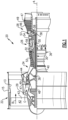
- FIG. 1 schematically illustrates a gas turbine engine 20.
- the gas turbine engine 20 is disclosed herein as a two-spool turbofan that generally incorporates a fan section 22, a compressor section 24, a combustor section 26 and a turbine section 28.
- the fan section 22 may include a single-stage fan 42 having a plurality of fan blades 43.
- the fan blades 43 may have a fixed stagger angle or may have a variable pitch to direct incoming airflow from an engine inlet.
- the fan 42 drives air along a bypass flow path B in a bypass duct 13 defined within a housing 15 such as a fan case or nacelle, and also drives air along a core flow path C for compression and communication into the combustor section 26 then expansion through the turbine section 28.
- a splitter 29 aft of the fan 42 divides the air between the bypass flow path B and the core flow path C.
- the housing 15 may surround the fan 42 to establish an outer diameter of the bypass duct 13.
- the splitter 29 may establish an inner diameter of the bypass duct 13.
- the exemplary engine 20 generally includes a low speed spool 30 and a high speed spool 32 mounted for rotation about an engine central longitudinal axis A relative to an engine static structure 36 via several bearing systems 38. It should be understood that various bearing systems 38 at various locations may alternatively or additionally be provided, and the location of bearing systems 38 may be varied as appropriate to the application.
- the low speed spool 30 generally includes an inner shaft 40 that interconnects, a first (or low) pressure compressor 44 and a first (or low) pressure turbine 46.
- the inner shaft 40 is connected to the fan 42 through a speed change mechanism, which in the exemplary gas turbine engine 20 is illustrated as a geared architecture 48 to drive the fan 42 at a lower speed than the low speed spool 30.
- the inner shaft 40 may interconnect the low pressure compressor 44 and low pressure turbine 46 such that the low pressure compressor 44 and low pressure turbine 46 are rotatable at a common speed and in a common direction.
- the low pressure turbine 46 drives both the fan 42 and low pressure compressor 44 through the geared architecture 48 such that the fan 42 and low pressure compressor 44 are rotatable at a common speed.
- the high speed spool 32 includes an outer shaft 50 that interconnects a second (or high) pressure compressor 52 and a second (or high) pressure turbine 54.
- a combustor 56 is arranged in the exemplary gas turbine 20 between the high pressure compressor 52 and the high pressure turbine 54.
- a mid-turbine frame 57 of the engine static structure 36 may be arranged generally between the high pressure turbine 54 and the low pressure turbine 46.
- the mid-turbine frame 57 further supports bearing systems 38 in the turbine section 28.
- the inner shaft 40 and the outer shaft 50 are concentric and rotate via bearing systems 38 about the engine central longitudinal axis A which is collinear with their longitudinal axes.
- Airflow in the core flow path C is compressed by the low pressure compressor 44 then the high pressure compressor 52, mixed and burned with fuel in the combustor 56, then expanded through the high pressure turbine 54 and low pressure turbine 46.
- the mid-turbine frame 57 includes airfoils 59 which are in the core flow path C.
- the turbines 46, 54 rotationally drive the respective low speed spool 30 and high speed spool 32 in response to the expansion.
- gear system 48 may be located aft of the low pressure compressor, or aft of the combustor section 26 or even aft of turbine section 28, and fan 42 may be positioned forward or aft of the location of gear system 48.
- the low pressure compressor 44, high pressure compressor 52, high pressure turbine 54 and low pressure turbine 46 each include one or more stages having a row of rotatable airfoils. Each stage may include a row of vanes adjacent the rotatable airfoils.
- the rotatable airfoils are schematically indicated at 47, and the vanes are schematically indicated at 49.
- the engine 20 may be a high-bypass geared aircraft engine.
- the bypass ratio can be greater than or equal to 10.0 and less than or equal to about 18.0, or more narrowly can be less than or equal to 16.0.
- the geared architecture 48 may be an epicyclic gear train, such as a planetary gear system or a star gear system.
- the epicyclic gear train may include a sun gear, a ring gear, a plurality of intermediate gears meshing with the sun gear and ring gear, and a carrier that supports the intermediate gears.
- the sun gear may provide an input to the gear train.
- the ring gear (e.g., star gear system) or carrier (e.g., planetary gear system) may provide an output of the gear train to drive the fan 42.
- a gear reduction ratio may be greater than or equal to 2.3, or more narrowly greater than or equal to 3.0, and in some embodiments the gear reduction ratio is greater than or equal to 3.4.
- the gear reduction ratio may be less than or equal to 4.0.
- the fan diameter is significantly larger than that of the low pressure compressor 44.
- the low pressure turbine 46 can have a pressure ratio that is greater than or equal to 8.0 and in some embodiments is greater than or equal to 10.0.
- the low pressure turbine pressure ratio can be less than or equal to 13.0, or more narrowly less than or equal to 12.0.
- Low pressure turbine 46 pressure ratio is pressure measured prior to an inlet of low pressure turbine 46 as related to the pressure at the outlet of the low pressure turbine 46 prior to an exhaust nozzle. It should be understood, however, that the above parameters are only exemplary of one embodiment of a geared architecture engine and that the present invention is applicable to other gas turbine engines including direct drive turbofans. All of these parameters are measured at the cruise condition described below.
- the fan section 22 of the engine 20 is designed for a particular flight condition -- typically cruise at about 0.8 Mach and about 35,000 feet (10,668 meters).
- the flight condition of 0.8 Mach and 35,000 ft (10,668 meters), with the engine at its best fuel consumption - also known as "bucket cruise Thrust Specific Fuel Consumption ('TSFC')" - is the industry standard parameter of lbm of fuel being burned divided by lbf of thrust the engine produces at that minimum point.
- 'TSFC' Thrust Specific Fuel Consumption
- Fan pressure ratio is the pressure ratio across the fan blade 43 alone, without a Fan Exit Guide Vane (“FEGV”) system.
- a distance is established in a radial direction between the inner and outer diameters of the bypass duct 13 at an axial position corresponding to a leading edge of the splitter 29 relative to the engine central longitudinal axis A.
- the fan pressure ratio is a spanwise average of the pressure ratios measured across the fan blade 43 alone over radial positions corresponding to the distance.
- the fan pressure ratio can be less than or equal to 1.45, or more narrowly greater than or equal to 1.25, such as between 1.30 and 1.40.
- “Corrected fan tip speed” is the actual fan tip speed in ft/sec divided by an industry standard temperature correction of [(Tram °R) / (518.7 °R)] 0.5 .
- the corrected fan tip speed can be less than or equal to 1150.0 ft / second (350.5 meters/second), and can be greater than or equal to 1000.0 ft / second (304.8 meters/second).
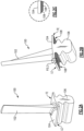
- FIGS 2A-B show an example blade 100 that can be used in, for example, the turbine section 28 of the engine 20.
- the blade 100 includes an airfoil section 102 that extends from a platform 104, and a mount 106 extending from the platform 104 in a direction opposite the direction of the airfoil section 102.
- the mount 106 is a "fir-tree" mount though other geometries are contemplated.
- the mount 106 has enlarged portions that are received in corresponding grooves of a rotor disk in a turbine 46/54 of the turbine section 28 to retain the blade 100 in the rotor disk (not shown).
- the blades 100 are formed of a composite material such as a polymer matrix composite ("PMC"), metal matrix composite (“MMC”), ceramic matrix composite (“CMC”), or a monolithic ceramic.
- a CMC material may be comprised of one or more ceramic reinforcements, such as fibers, in a ceramic matrix.
- ceramic matrices are silicon-containing ceramics, such as but not limited to, a silicon carbide (SiC) matrix or a silicon nitride (Si3N4) matrix.
- Example ceramic reinforcement of the CMC are silicon-containing ceramic fibers, such as but not limited to, silicon carbide (SiC) fiber or silicon nitride (Si3N4) fibers.
- the CMC may be, but is not limited to, a SiC/SiC ceramic matrix composite in which SiC fiber plies are disposed within a SiC matrix.
- the fibers may be arranged in fiber plies, is an ordered arrangement of the fiber tows/yarns relative to one another, such as a 2D/3D weave, braid, knit, or a nonwoven structure.
- a monolithic ceramic does not contain fibers or reinforcement and is comprised of a single material.
- Example monolithic ceramics include silicon-containing ceramics, such as silicon carbide (SiC) or silicon nitride (Si3N4).
- Each blade 100 may include a combination of the aforementioned materials.
- the airfoil section may be a CMC while the mount 106 is metallic or has metallic components.
- the blade 100 may be subject to vibratory forces. Damping these vibratory forces is typically achieved by attaching a damper to the blade.
- the damper has a mass and geometry, and is attached at a particular location of the blade 10, selected to reduce vibratory loads on the blade 100.
- the present blade 100 includes a damper 108 deposited directly onto the blade 100. That is, there are no fasteners attaching the damper 108 to the blade 100.
- the damper 108 is attached to the blade 100 by virtue of the deposition process.
- the damper 108 comprises a machinable material deposited in a discrete area of the blade 100. That is, the damper 108 is "machinable" in that it can be subject to grinding, ultrasonic machining, water guided laser, milling, reaming, or another machining methods known in the art to reduce its thickness and/or smooth its surface without any adverse effects to its integrity. In this way, the geometry and mass of the damper 108 can be fine-tuned as will be discussed in more detail below.
- the material of the damper 108 may include rare earth silicates, alkaline earth silicates, alkaline earth aluminosilicates, yttria-stabilized zirconia, alumina-stabilized zirconia, mullite, titania, chromia, silicon, silicon oxides, silicon carbides, silicon oxycarbides, silicon nitride, silicon-aluminum-oxygen-nitrogen, barium-magnesium aluminosilicate, hafnium oxides such as hafnon, hafnium silicon oxides, alumina-stabilized zirconia, zirconium oxides such as zircon, yttrium oxides such as yttria, and combinations thereof.
- the material coating includes at least one of hafnon, zircon, and mullite.
- the damper 108 is located on the non-gas-path, or radially outer, surface of the platform 104.
- the damper 108 may be on a leading edge (LE) side of the platform 108, a trailing edge (TE) side of the platform 108, or both. Because the damper 108 is in this example out of the gas path, it is less susceptible to foreign object damage and/or environmental degradation.
- the damper 108 may optionally have a tapered edge 109 to form a smooth transition between the platform 104 and the damper 108, which improves the aerodynamic performance of the blade 100, as shown in the detail view of Figure 2C .
- the damper 108 can be deposited onto the blade 100 by any suitable method known in the art, such as plasma spray, slurry coating, chemical vapor deposition (CVD), physical vapor deposition, electron beam physical deposition, or others. In some examples, areas of the blade 100 outside of the discrete area of the damper 100 are masked prior the deposition of the damper 108.
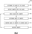
- the damper is sized according to an iterative process schematically illustrated in Figures 3 .
- an example method 300 of sizing the damper 108 determining the mass of the blade 100 in step 302.
- an oversized damper 108 is deposited onto the blade 100.
- the blade 100 with damper is weighed.
- the mass of the damper 108 is determined by determining the mass of the blade 100 with damper 108 after step 304 and subtracting the mass of the blade 100 from step 302.
- the mass of the damper from step 308 is compared to a predetermined desired damper 108 mass.
- steps 306 through 312 are repeated the damper 108 is machined as described above to remove mass from the damper 108. Steps 306, 308, and 310, and 312 are then repeated until the mass of the damper 108 is the desired mass.
Landscapes
- Engineering & Computer Science (AREA)
- Chemical & Material Sciences (AREA)
- Mechanical Engineering (AREA)
- General Engineering & Computer Science (AREA)
- Materials Engineering (AREA)
- Ceramic Engineering (AREA)
- Composite Materials (AREA)
- Turbine Rotor Nozzle Sealing (AREA)
Abstract
A gas turbine engine blade (100) includes a platform (104), an airfoil section (102) extending from the platform (104) in a first direction, a mount (106) extending from the platform (104) in a second direction opposite the first direction, and a damper (108) deposited on one of the platform (104), the airfoil section (102), and the mount (106). A method of sizing a damper (108) for a gas turbine engine blade (100)is also disclosed.
Description
- This application relates to a mount structure and turbine blade for use in a gas turbine engine turbine section.
- Gas turbine engines are known, and in some examples include a fan delivering air into a bypass duct as propulsion air. The fan also delivers air into a compressor. Compressed air is delivered downstream to a combustor where it is mixed with fuel and ignited. Products of this combustion pass downstream over turbine rotors, driving them to rotate. The turbine rotors in turn rotate fan and compressor rotors.
- As can be appreciated, the turbine section sees very high temperatures from the products of combustion. Thus, a good deal of effort is expended in trying to provide turbine components that can survive the high temperatures. Other types of engines may also benefit from high-temperature components.
- One recent materials approach for providing turbine section components, and other components of an engine, is the use of ceramic matrix composites ("CMCs"). There is a need for improved adaptation of CMCs for use in engines.
- From one aspect, there is provided a gas turbine engine blade that, among other possible things, includes a platform, an airfoil section extending from the platform in a first direction, a mount extending from the platform in a second direction opposite the first direction, and a damper deposited on one of the platform, the airfoil section, and the mount.
- In a further example of the foregoing, the damper is machinable.
- In a further example of any of the foregoing, the damper includes at least one of rare earth silicates, alkaline earth silicates, alkaline earth aluminosilicates, yttria-stabilized zirconia, alumina-stabilized zirconia, mullite, titania, chromia, silicon, silicon oxides, silicon carbides, silicon oxycarbides, silicon nitride, silicon-aluminum-oxygen-nitrogen, barium-magnesium aluminosilicate, hafnium oxides such as hafnon, hafnium silicon oxides, alumina-stabilized zirconia, zirconium oxides such as zircon, yttrium oxides such as yttria, and combinations thereof.
- In a further example of any of the foregoing, the damper includes at least one of hafnon, zircon, and mullite.
- In a further example of any of the foregoing, the blade is one of a ceramic matrix composite blade or a monolithic ceramic blade.
- In a further example of any of the foregoing, the damper is on the platform.
- In a further example of any of the foregoing, the damper is on a non-gas-path surface of the platform.
- In a further example of any of the foregoing, the blade comprises a ceramic matrix composite.
- In a further example of any of the foregoing, the blade comprises a monolithic ceramic material.
- In a further example of any of the foregoing, there are no fasteners attaching the damper to the blade.
- There is also provided a method of sizing a damper for a gas turbine engine blade that, among other possible things, includes determining the mass of a blade, depositing a damper onto the blade, determining a mass of the damper after the depositing step, and machining the damper to remove mass.
- In a further example of the foregoing, the method also includes comparing a mass of the damper to a desired mass.
- In a further example of any of the foregoing, the method also includes repeating the machining step if the mass of the damper is larger than the desired mass.
- In a further example of any of the foregoing, the depositing is by at least one of plasma spray, slurry coating, chemical vapor deposition (CVD), physical vapor deposition, and electron beam physical deposition
- In a further example of any of the foregoing, the machining is by grinding, ultrasonic machining, water guided laser, milling, or reaming.
- In a further example of any of the foregoing, the blade is one of a ceramic matrix composite blade or a monolithic ceramic blade.
- In a further example of any of the foregoing, the deposition attaches the damper to the blade without any fasteners.
- In a further example of any of the foregoing, the blade includes an airfoil section, a platform, and a mount. The damper is deposited onto the platform.
- In a further example of any of the foregoing, the damper is deposited onto a non-gas-path surface of the platform.
- In a further example of any of the foregoing, the damper includes at least one of rare earth silicates, alkaline earth silicates, alkaline earth aluminosilicates, yttria-stabilized zirconia, alumina-stabilized zirconia, mullite, titania, chromia, silicon, silicon oxides, silicon carbides, silicon oxycarbides, silicon nitride, silicon-aluminum oxygen-nitrogen, barium-magnesium aluminosilicate, hafnium oxides such as hafnon, hafnium silicon oxides, alumina-stabilized zirconia, zirconium oxides such as zircon, yttrium oxides such as yttria, and combinations thereof.
-
-
Figure 1 schematically shows a gas turbine engine. -
Figures 2A-C show alternate views of an example turbine blade for the gas turbine engine ofFigure 1 . -
Figure 3 shows an example method of sizing a damper for a turbine blade such as the example blades ofFigures 2A-B . -
Figure 1 schematically illustrates agas turbine engine 20. Thegas turbine engine 20 is disclosed herein as a two-spool turbofan that generally incorporates afan section 22, acompressor section 24, a combustor section 26 and aturbine section 28. Thefan section 22 may include a single-stage fan 42 having a plurality offan blades 43. Thefan blades 43 may have a fixed stagger angle or may have a variable pitch to direct incoming airflow from an engine inlet. Thefan 42 drives air along a bypass flow path B in abypass duct 13 defined within ahousing 15 such as a fan case or nacelle, and also drives air along a core flow path C for compression and communication into the combustor section 26 then expansion through theturbine section 28. Asplitter 29 aft of thefan 42 divides the air between the bypass flow path B and the core flow path C. Thehousing 15 may surround thefan 42 to establish an outer diameter of thebypass duct 13. Thesplitter 29 may establish an inner diameter of thebypass duct 13. Although depicted as a two-spool turbofan gas turbine engine in the disclosed nonlimiting embodiment, it should be understood that the concepts described herein are not limited to use with two-spool turbofans as the teachings may be applied to other types of turbine engines including three-spool architectures. Theengine 20 may incorporate a variable area nozzle for varying an exit area of the bypass flow path B and/or a thrust reverser for generating reverse thrust. - The
exemplary engine 20 generally includes alow speed spool 30 and ahigh speed spool 32 mounted for rotation about an engine central longitudinal axis A relative to an enginestatic structure 36 viaseveral bearing systems 38. It should be understood thatvarious bearing systems 38 at various locations may alternatively or additionally be provided, and the location ofbearing systems 38 may be varied as appropriate to the application. - The
low speed spool 30 generally includes aninner shaft 40 that interconnects, a first (or low)pressure compressor 44 and a first (or low)pressure turbine 46. Theinner shaft 40 is connected to thefan 42 through a speed change mechanism, which in the exemplarygas turbine engine 20 is illustrated as a gearedarchitecture 48 to drive thefan 42 at a lower speed than thelow speed spool 30. Theinner shaft 40 may interconnect thelow pressure compressor 44 andlow pressure turbine 46 such that thelow pressure compressor 44 andlow pressure turbine 46 are rotatable at a common speed and in a common direction. In other embodiments, thelow pressure turbine 46 drives both thefan 42 andlow pressure compressor 44 through the gearedarchitecture 48 such that thefan 42 andlow pressure compressor 44 are rotatable at a common speed. Although this application discloses gearedarchitecture 48, its teaching may benefit direct drive engines having no geared architecture. Thehigh speed spool 32 includes anouter shaft 50 that interconnects a second (or high)pressure compressor 52 and a second (or high)pressure turbine 54. Acombustor 56 is arranged in theexemplary gas turbine 20 between thehigh pressure compressor 52 and thehigh pressure turbine 54. Amid-turbine frame 57 of the enginestatic structure 36 may be arranged generally between thehigh pressure turbine 54 and thelow pressure turbine 46. Themid-turbine frame 57 further supports bearingsystems 38 in theturbine section 28. Theinner shaft 40 and theouter shaft 50 are concentric and rotate viabearing systems 38 about the engine central longitudinal axis A which is collinear with their longitudinal axes. - Airflow in the core flow path C is compressed by the
low pressure compressor 44 then thehigh pressure compressor 52, mixed and burned with fuel in thecombustor 56, then expanded through thehigh pressure turbine 54 andlow pressure turbine 46. Themid-turbine frame 57 includesairfoils 59 which are in the core flow path C. Theturbines low speed spool 30 andhigh speed spool 32 in response to the expansion. It will be appreciated that each of the positions of thefan section 22,compressor section 24, combustor section 26,turbine section 28, and fandrive gear system 48 may be varied. For example,gear system 48 may be located aft of the low pressure compressor, or aft of the combustor section 26 or even aft ofturbine section 28, andfan 42 may be positioned forward or aft of the location ofgear system 48. - The
low pressure compressor 44,high pressure compressor 52,high pressure turbine 54 andlow pressure turbine 46 each include one or more stages having a row of rotatable airfoils. Each stage may include a row of vanes adjacent the rotatable airfoils. The rotatable airfoils are schematically indicated at 47, and the vanes are schematically indicated at 49. - The
engine 20 may be a high-bypass geared aircraft engine. The bypass ratio can be greater than or equal to 10.0 and less than or equal to about 18.0, or more narrowly can be less than or equal to 16.0. The gearedarchitecture 48 may be an epicyclic gear train, such as a planetary gear system or a star gear system. The epicyclic gear train may include a sun gear, a ring gear, a plurality of intermediate gears meshing with the sun gear and ring gear, and a carrier that supports the intermediate gears. The sun gear may provide an input to the gear train. The ring gear (e.g., star gear system) or carrier (e.g., planetary gear system) may provide an output of the gear train to drive thefan 42. A gear reduction ratio may be greater than or equal to 2.3, or more narrowly greater than or equal to 3.0, and in some embodiments the gear reduction ratio is greater than or equal to 3.4. The gear reduction ratio may be less than or equal to 4.0. The fan diameter is significantly larger than that of thelow pressure compressor 44. Thelow pressure turbine 46 can have a pressure ratio that is greater than or equal to 8.0 and in some embodiments is greater than or equal to 10.0. The low pressure turbine pressure ratio can be less than or equal to 13.0, or more narrowly less than or equal to 12.0.Low pressure turbine 46 pressure ratio is pressure measured prior to an inlet oflow pressure turbine 46 as related to the pressure at the outlet of thelow pressure turbine 46 prior to an exhaust nozzle. It should be understood, however, that the above parameters are only exemplary of one embodiment of a geared architecture engine and that the present invention is applicable to other gas turbine engines including direct drive turbofans. All of these parameters are measured at the cruise condition described below. - A significant amount of thrust is provided by the bypass flow B due to the high bypass ratio. The
fan section 22 of theengine 20 is designed for a particular flight condition -- typically cruise at about 0.8 Mach and about 35,000 feet (10,668 meters). The flight condition of 0.8 Mach and 35,000 ft (10,668 meters), with the engine at its best fuel consumption - also known as "bucket cruise Thrust Specific Fuel Consumption ('TSFC')" - is the industry standard parameter of lbm of fuel being burned divided by lbf of thrust the engine produces at that minimum point. The engine parameters described above, and those in the next paragraph are measured at this condition unless otherwise specified. - "Fan pressure ratio" is the pressure ratio across the
fan blade 43 alone, without a Fan Exit Guide Vane ("FEGV") system. A distance is established in a radial direction between the inner and outer diameters of thebypass duct 13 at an axial position corresponding to a leading edge of thesplitter 29 relative to the engine central longitudinal axis A. The fan pressure ratio is a spanwise average of the pressure ratios measured across thefan blade 43 alone over radial positions corresponding to the distance. The fan pressure ratio can be less than or equal to 1.45, or more narrowly greater than or equal to 1.25, such as between 1.30 and 1.40. "Corrected fan tip speed" is the actual fan tip speed in ft/sec divided by an industry standard temperature correction of [(Tram °R) / (518.7 °R)]0.5. The corrected fan tip speed can be less than or equal to 1150.0 ft / second (350.5 meters/second), and can be greater than or equal to 1000.0 ft / second (304.8 meters/second). -
Figures 2A-B show anexample blade 100 that can be used in, for example, theturbine section 28 of theengine 20. Theblade 100 includes anairfoil section 102 that extends from aplatform 104, and amount 106 extending from theplatform 104 in a direction opposite the direction of theairfoil section 102. In this example themount 106 is a "fir-tree" mount though other geometries are contemplated. In general, themount 106 has enlarged portions that are received in corresponding grooves of a rotor disk in aturbine 46/54 of theturbine section 28 to retain theblade 100 in the rotor disk (not shown). - The
blades 100 are formed of a composite material such as a polymer matrix composite ("PMC"), metal matrix composite ("MMC"), ceramic matrix composite ("CMC"), or a monolithic ceramic. A CMC material may be comprised of one or more ceramic reinforcements, such as fibers, in a ceramic matrix. Example of ceramic matrices are silicon-containing ceramics, such as but not limited to, a silicon carbide (SiC) matrix or a silicon nitride (Si3N4) matrix. Example ceramic reinforcement of the CMC are silicon-containing ceramic fibers, such as but not limited to, silicon carbide (SiC) fiber or silicon nitride (Si3N4) fibers. The CMC may be, but is not limited to, a SiC/SiC ceramic matrix composite in which SiC fiber plies are disposed within a SiC matrix. The fibers may be arranged in fiber plies, is an ordered arrangement of the fiber tows/yarns relative to one another, such as a 2D/3D weave, braid, knit, or a nonwoven structure. A monolithic ceramic does not contain fibers or reinforcement and is comprised of a single material. Example monolithic ceramics include silicon-containing ceramics, such as silicon carbide (SiC) or silicon nitride (Si3N4). - Each
blade 100 may include a combination of the aforementioned materials. For instance the airfoil section may be a CMC while themount 106 is metallic or has metallic components. - During operation of the
engine 20, theblade 100 may be subject to vibratory forces. Damping these vibratory forces is typically achieved by attaching a damper to the blade. The damper has a mass and geometry, and is attached at a particular location of the blade 10, selected to reduce vibratory loads on theblade 100. However, it would be beneficial to achieve damping of the vibratory loads without needing to attach separate structures to theblade 100, as this process increases cost and complexity of manufacturing theblade 100 or retrofitting it in the event damping is needed. - Accordingly, the
present blade 100 includes adamper 108 deposited directly onto theblade 100. That is, there are no fasteners attaching thedamper 108 to theblade 100. Thedamper 108 is attached to theblade 100 by virtue of the deposition process. - More specifically, the
damper 108 comprises a machinable material deposited in a discrete area of theblade 100. That is, thedamper 108 is "machinable" in that it can be subject to grinding, ultrasonic machining, water guided laser, milling, reaming, or another machining methods known in the art to reduce its thickness and/or smooth its surface without any adverse effects to its integrity. In this way, the geometry and mass of thedamper 108 can be fine-tuned as will be discussed in more detail below. - The material of the
damper 108 may include rare earth silicates, alkaline earth silicates, alkaline earth aluminosilicates, yttria-stabilized zirconia, alumina-stabilized zirconia, mullite, titania, chromia, silicon, silicon oxides, silicon carbides, silicon oxycarbides, silicon nitride, silicon-aluminum-oxygen-nitrogen, barium-magnesium aluminosilicate, hafnium oxides such as hafnon, hafnium silicon oxides, alumina-stabilized zirconia, zirconium oxides such as zircon, yttrium oxides such as yttria, and combinations thereof. In a particular example, the material coating includes at least one of hafnon, zircon, and mullite. - In the example of
Figures 2A-B , thedamper 108 is located on the non-gas-path, or radially outer, surface of theplatform 104. Thedamper 108 may be on a leading edge (LE) side of theplatform 108, a trailing edge (TE) side of theplatform 108, or both. Because thedamper 108 is in this example out of the gas path, it is less susceptible to foreign object damage and/or environmental degradation. - The
damper 108 may optionally have a taperededge 109 to form a smooth transition between theplatform 104 and thedamper 108, which improves the aerodynamic performance of theblade 100, as shown in the detail view ofFigure 2C . - The
damper 108 can be deposited onto theblade 100 by any suitable method known in the art, such as plasma spray, slurry coating, chemical vapor deposition (CVD), physical vapor deposition, electron beam physical deposition, or others. In some examples, areas of theblade 100 outside of the discrete area of thedamper 100 are masked prior the deposition of thedamper 108. - In one example, the damper is sized according to an iterative process schematically illustrated in
Figures 3 . As shown inFigure 3 , anexample method 300 of sizing thedamper 108 determining the mass of theblade 100 instep 302. Instep 304, anoversized damper 108 is deposited onto theblade 100. Instep 306, theblade 100 with damper is weighed. Instep 308, the mass of thedamper 108 is determined by determining the mass of theblade 100 withdamper 108 afterstep 304 and subtracting the mass of theblade 100 fromstep 302. Instep 310, the mass of the damper fromstep 308 is compared to a predetermined desireddamper 108 mass. If the mass is too high,steps 306 through 312 are repeated thedamper 108 is machined as described above to remove mass from thedamper 108.Steps damper 108 is the desired mass. - As used herein, the term "about" has the typical meaning in the art, however in a particular example "about" can mean deviations of up to 10% of the values described herein.
- Although a combination of features is shown in the illustrated examples, not all of them need to be combined to realize the benefits of various embodiments of this disclosure. In other words, a system designed according to an embodiment of this disclosure will not necessarily include all of the features shown in any one of the figures or all of the portions schematically shown in the figures. Moreover, selected features of one example embodiment may be combined with selected features of other example embodiments.
- Although an embodiment of this invention has been disclosed, a worker of ordinary skill in this art would recognize that certain modifications would come within the scope of this disclosure. For that reason, the following claims should be studied to determine the true scope and content of this disclosure.
Claims (15)
- A gas turbine engine blade (100), comprising:a platform (104);an airfoil section (102) extending from the platform (104) in a first direction;a mount (106) extending from the platform (104) in a second direction opposite the first direction; anda damper (108) deposited on one of the platform (104), the airfoil section (102), and the mount (106).
- The gas turbine engine blade of claim 1, wherein the damper (108) is machinable.
- The gas turbine engine blade of claim 1 or 2, wherein the damper (108) is on the platform (104), optionally on a non-gas-path surface of the platform (104).
- The gas turbine engine blade of any preceding claim, where there are no fasteners attaching the damper (108) to the blade (104).
- A method of sizing a damper (108) for a gas turbine engine blade (100), comprising:determining the mass of a blade (100);depositing a damper (108) onto the blade (100);determining a mass of the damper (108) after the depositing step; andmachining the damper (108) to remove mass.
- The method of claim 5, further comprising comparing a mass of the damper (108) to a desired mass.
- The method of claim 6, further comprising repeating the machining step if the mass of the damper (108) is larger than the desired mass.
- The method of any of claims 5 to 7, wherein the depositing is by at least one of plasma spray, slurry coating, chemical vapor deposition (CVD), physical vapor deposition, and electron beam physical deposition.
- The method of any of claims 5 to 8, wherein the machining is by grinding, ultrasonic machining, water guided laser, milling, or reaming.
- The method of any of claims 5 to 9, wherein the deposition attaches the damper (108) to the blade (100) without any fasteners.
- The method of any of claims 5 to 10, wherein the blade (100) includes an airfoil section (102), a platform (104), and a mount (106), and wherein the damper (108) is deposited onto the platform (104).
- The method of claim 11, wherein the damper (108) is deposited onto a non-gas-path surface of the platform (104).
- The method or gas turbine engine blade of any preceding claim, wherein the blade (100) is one of a ceramic matrix composite blade (100) or a monolithic ceramic blade (100).
- The method or gas turbine engine blade of any preceding claim, wherein the damper (108) includes at least one of rare earth silicates, alkaline earth silicates, alkaline earth aluminosilicates, yttria-stabilized zirconia, alumina-stabilized zirconia, mullite, titania, chromia, silicon, silicon oxides, silicon carbides, silicon oxycarbides, silicon nitride, silicon-aluminum-oxygen-nitrogen, barium-magnesium aluminosilicate, hafnium oxides such as hafnon, hafnium silicon oxides, zirconium oxides such as zircon, yttrium oxides such as yttria, and combinations thereof.
- The gas turbine engine blade or method of claim 14, wherein the damper (108) includes at least one of hafnon, zircon, and mullite.
Applications Claiming Priority (1)
| Application Number | Priority Date | Filing Date | Title |
|---|---|---|---|
| US18/169,176 US20240271537A1 (en) | 2023-02-14 | 2023-02-14 | Machinable coating for damping |
Publications (1)
| Publication Number | Publication Date |
|---|---|
| EP4417788A1 true EP4417788A1 (en) | 2024-08-21 |
Family
ID=89901221
Family Applications (1)
| Application Number | Title | Priority Date | Filing Date |
|---|---|---|---|
| EP24156941.7A Pending EP4417788A1 (en) | 2023-02-14 | 2024-02-09 | Gas turbine engine blade and method of sizing a damper for a gas turbine engine blade |
Country Status (2)
| Country | Link |
|---|---|
| US (1) | US20240271537A1 (en) |
| EP (1) | EP4417788A1 (en) |
Citations (6)
| Publication number | Priority date | Publication date | Assignee | Title |
|---|---|---|---|---|
| JPS58211845A (en) * | 1982-06-01 | 1983-12-09 | Toyota Motor Corp | Ceramic rotary element with balance correcting lugs |
| US4580946A (en) * | 1984-11-26 | 1986-04-08 | General Electric Company | Fan blade platform seal |
| JPS63198702A (en) * | 1987-02-14 | 1988-08-17 | Toyota Motor Corp | Turbine wheel |
| DE102004037608A1 (en) * | 2004-08-03 | 2006-03-16 | Rolls-Royce Deutschland Ltd & Co Kg | Gas turbine engine`s rotary aviation component e.g. blade of blisk disk, balancing method, involves applying material of selected mass by material coating procedure at selected place of component based on result of balance test |
| US20190338645A1 (en) * | 2015-12-28 | 2019-11-07 | Siemens Aktiengesellschaft | Method for producing a base body of a turbine blade |
| US20210402536A1 (en) * | 2019-03-29 | 2021-12-30 | Hirata Corporation | Manufacturing system |
Family Cites Families (28)
| Publication number | Priority date | Publication date | Assignee | Title |
|---|---|---|---|---|
| US4422827A (en) * | 1982-02-18 | 1983-12-27 | United Technologies Corporation | Blade root seal |
| US6494679B1 (en) * | 1999-08-05 | 2002-12-17 | General Electric Company | Apparatus and method for rotor damping |
| US6451416B1 (en) * | 1999-11-19 | 2002-09-17 | United Technologies Corporation | Hybrid monolithic ceramic and ceramic matrix composite airfoil and method for making the same |
| SG96589A1 (en) * | 1999-12-20 | 2003-06-16 | United Technologies Corp | Methods of providing article with corrosion resistant coating and coated article |
| US6270318B1 (en) * | 1999-12-20 | 2001-08-07 | United Technologies Corporation | Article having corrosion resistant coating |
| FR2874403B1 (en) * | 2004-08-23 | 2006-09-29 | Snecma Moteurs Sa | COMPRESSOR VANE OR GAS TURBUNE |
| FR2918109B1 (en) * | 2007-06-26 | 2013-05-24 | Snecma | MOBILE WHEEL FOR A TURBOJET AND TURBOJET COMPRISING THE SAME |
| FR2918108B1 (en) * | 2007-06-26 | 2009-10-02 | Snecma Sa | SHOCK ABSORBER DEVICE FOR TURBOMACHINE STATOR |
| US8173206B2 (en) * | 2007-12-20 | 2012-05-08 | General Electric Company | Methods for repairing barrier coatings |
| US8591196B2 (en) * | 2008-06-18 | 2013-11-26 | General Electric Company | Vibration damping novel surface structures and methods of making the same |
| US9011104B2 (en) * | 2010-01-06 | 2015-04-21 | General Electric Company | Articles having damping coatings thereon |
| US8672626B2 (en) * | 2010-04-21 | 2014-03-18 | United Technologies Corporation | Engine assembled seal |
| JP5591152B2 (en) * | 2011-02-28 | 2014-09-17 | 三菱重工業株式会社 | Turbine blade |
| US20130210299A1 (en) * | 2012-02-09 | 2013-08-15 | General Electric Company | Reinforced coatings and methods of making the same |
| CN102797509B (en) * | 2012-08-24 | 2014-09-17 | 中国南方航空工业(集团)有限公司 | Shock absorption/lubrication structure of turbine blade |
| US11268526B2 (en) * | 2013-07-09 | 2022-03-08 | Raytheon Technologies Corporation | Plated polymer fan |
| US10023951B2 (en) * | 2013-10-22 | 2018-07-17 | Mo-How Herman Shen | Damping method including a face-centered cubic ferromagnetic damping material, and components having same |
| DE102015203868A1 (en) * | 2015-03-04 | 2016-09-08 | Rolls-Royce Deutschland Ltd & Co Kg | Fan blade for a propulsion system |
| US10196915B2 (en) * | 2015-06-01 | 2019-02-05 | United Technologies Corporation | Trailing edge platform seals |
| FR3051187B1 (en) * | 2016-05-11 | 2018-06-01 | Safran Ceramics | PIECE OF COMPOSITE MATERIAL |
| DE102017212075A1 (en) * | 2017-07-14 | 2019-01-17 | MTU Aero Engines AG | Process for coating a component for the hot gas duct of a turbomachine |
| EP3611146B1 (en) * | 2018-08-16 | 2021-03-24 | Raytheon Technologies Corporation | Machinable coatings fabricated by slurry methods for use on ceramic matrix composites |
| US11143040B2 (en) * | 2019-10-02 | 2021-10-12 | Raytheon Technologies Corporation | Ceramic matrix composite rotor blade attachment and method of manufacture therefor |
| FR3107914B1 (en) * | 2020-03-03 | 2022-02-04 | Safran Aircraft Engines | COMPOSITE PLATFORM FOR AN AIRCRAFT TURBOMACHINE FAN |
| FR3107923B1 (en) * | 2020-03-03 | 2022-02-04 | Safran Aircraft Engines | METHOD FOR MANUFACTURING A COMPOSITE PLATFORM FOR AN AIRCRAFT TURBOMACHINE FAN |
| US11242756B2 (en) * | 2020-05-04 | 2022-02-08 | General Electric Company | Damping coating with a constraint layer |
| US12071380B2 (en) * | 2020-09-16 | 2024-08-27 | Rolls-Royce High Temperature Composites, Inc. | Method to fabricate a machinable ceramic matrix composite |
| US20230117555A1 (en) * | 2021-10-15 | 2023-04-20 | Raytheon Technologies Corporation | Blade vibration mitigation of integrally bladed rotor by damping on disk |
-
2023
- 2023-02-14 US US18/169,176 patent/US20240271537A1/en not_active Abandoned
-
2024
- 2024-02-09 EP EP24156941.7A patent/EP4417788A1/en active Pending
Patent Citations (6)
| Publication number | Priority date | Publication date | Assignee | Title |
|---|---|---|---|---|
| JPS58211845A (en) * | 1982-06-01 | 1983-12-09 | Toyota Motor Corp | Ceramic rotary element with balance correcting lugs |
| US4580946A (en) * | 1984-11-26 | 1986-04-08 | General Electric Company | Fan blade platform seal |
| JPS63198702A (en) * | 1987-02-14 | 1988-08-17 | Toyota Motor Corp | Turbine wheel |
| DE102004037608A1 (en) * | 2004-08-03 | 2006-03-16 | Rolls-Royce Deutschland Ltd & Co Kg | Gas turbine engine`s rotary aviation component e.g. blade of blisk disk, balancing method, involves applying material of selected mass by material coating procedure at selected place of component based on result of balance test |
| US20190338645A1 (en) * | 2015-12-28 | 2019-11-07 | Siemens Aktiengesellschaft | Method for producing a base body of a turbine blade |
| US20210402536A1 (en) * | 2019-03-29 | 2021-12-30 | Hirata Corporation | Manufacturing system |
Also Published As
| Publication number | Publication date |
|---|---|
| US20240271537A1 (en) | 2024-08-15 |
Similar Documents
| Publication | Publication Date | Title |
|---|---|---|
| EP4596839A1 (en) | Blade outer air seal, gas turbine engine and method of coating a blade outer air seal | |
| EP4603679A1 (en) | Blade outer air seal with machinable coating at sealing surfaces | |
| EP4379190B1 (en) | Removable layer to adjust mount structure of a turbine vane for re-stagger | |
| US12331654B2 (en) | Bathtub seal for damping CMC vane platform | |
| EP4353949B1 (en) | Gas turbine engine vane and spar combination with variable air flow path | |
| EP4385969A1 (en) | Article and method of making an article by chemical vapor infiltration | |
| EP4417788A1 (en) | Gas turbine engine blade and method of sizing a damper for a gas turbine engine blade | |
| US12571315B2 (en) | Blade with damper land | |
| US12291971B1 (en) | Blade outer air seal with graded coating | |
| US12448708B2 (en) | Extended inner profile for mandrel for use in forming braided CMC structures | |
| US12258867B1 (en) | Attachment for blade outer air seal | |
| US12601267B2 (en) | Forming gas turbine engine airfoils from CMCs with a kickback to facilitate mandrel removal | |
| EP4603246A1 (en) | Multi-piece mandrel for building up airfoil structure | |
| EP4385968A1 (en) | Article and method of making a ceramic matrix composite article | |
| US12012870B1 (en) | Machinable coating for CMC and metal interface in a turbine section | |
| EP4080018B1 (en) | Vane arc segment with flange having step and method of fabricating a vane arc segment | |
| EP4386181A1 (en) | Gas turbine engine coating with thermal protection | |
| EP4372207B1 (en) | Blade outer air seal with large radius of curvature mount hooks | |
| EP4403748A1 (en) | Sealing between ceramic and metallic component of a gas turbine engine | |
| EP4386180A1 (en) | Gas turbine engine coating with thermal protection | |
| EP4549701A1 (en) | Combined gas turbine engine vane and blade outer air seal assembly and gas turbine engine | |
| EP4361405A1 (en) | Gas turbine engine turbine section with axial seal | |
| EP4517049A1 (en) | Bathtub seal integrated into cmc vane load path |
Legal Events
| Date | Code | Title | Description |
|---|---|---|---|
| PUAI | Public reference made under article 153(3) epc to a published international application that has entered the european phase |
Free format text: ORIGINAL CODE: 0009012 |
|
| STAA | Information on the status of an ep patent application or granted ep patent |
Free format text: STATUS: THE APPLICATION HAS BEEN PUBLISHED |
|
| AK | Designated contracting states |
Kind code of ref document: A1 Designated state(s): AL AT BE BG CH CY CZ DE DK EE ES FI FR GB GR HR HU IE IS IT LI LT LU LV MC ME MK MT NL NO PL PT RO RS SE SI SK SM TR |
|
| STAA | Information on the status of an ep patent application or granted ep patent |
Free format text: STATUS: REQUEST FOR EXAMINATION WAS MADE |
|
| 17P | Request for examination filed |
Effective date: 20250212 |