EP4417787A1 - Roots type vacuum pump - Google Patents
Roots type vacuum pump Download PDFInfo
- Publication number
- EP4417787A1 EP4417787A1 EP24156227.1A EP24156227A EP4417787A1 EP 4417787 A1 EP4417787 A1 EP 4417787A1 EP 24156227 A EP24156227 A EP 24156227A EP 4417787 A1 EP4417787 A1 EP 4417787A1
- Authority
- EP
- European Patent Office
- Prior art keywords
- roots
- rotor
- roots rotor
- arcuate
- vacuum pump
- Prior art date
- Legal status (The legal status is an assumption and is not a legal conclusion. Google has not performed a legal analysis and makes no representation as to the accuracy of the status listed.)
- Pending
Links
Images



Classifications
-
- F—MECHANICAL ENGINEERING; LIGHTING; HEATING; WEAPONS; BLASTING
- F04—POSITIVE - DISPLACEMENT MACHINES FOR LIQUIDS; PUMPS FOR LIQUIDS OR ELASTIC FLUIDS
- F04C—ROTARY-PISTON, OR OSCILLATING-PISTON, POSITIVE-DISPLACEMENT MACHINES FOR LIQUIDS; ROTARY-PISTON, OR OSCILLATING-PISTON, POSITIVE-DISPLACEMENT PUMPS
- F04C18/00—Rotary-piston pumps specially adapted for elastic fluids
- F04C18/08—Rotary-piston pumps specially adapted for elastic fluids of intermeshing-engagement type, i.e. with engagement of co-operating members similar to that of toothed gearing
- F04C18/12—Rotary-piston pumps specially adapted for elastic fluids of intermeshing-engagement type, i.e. with engagement of co-operating members similar to that of toothed gearing of other than internal-axis type
- F04C18/126—Rotary-piston pumps specially adapted for elastic fluids of intermeshing-engagement type, i.e. with engagement of co-operating members similar to that of toothed gearing of other than internal-axis type with radially from the rotor body extending elements, not necessarily co-operating with corresponding recesses in the other rotor, e.g. lobes, Roots type
-
- F—MECHANICAL ENGINEERING; LIGHTING; HEATING; WEAPONS; BLASTING
- F01—MACHINES OR ENGINES IN GENERAL; ENGINE PLANTS IN GENERAL; STEAM ENGINES
- F01C—ROTARY-PISTON OR OSCILLATING-PISTON MACHINES OR ENGINES
- F01C21/00—Component parts, details or accessories not provided for in groups F01C1/00 - F01C20/00
- F01C21/08—Rotary pistons
-
- F—MECHANICAL ENGINEERING; LIGHTING; HEATING; WEAPONS; BLASTING
- F04—POSITIVE - DISPLACEMENT MACHINES FOR LIQUIDS; PUMPS FOR LIQUIDS OR ELASTIC FLUIDS
- F04C—ROTARY-PISTON, OR OSCILLATING-PISTON, POSITIVE-DISPLACEMENT MACHINES FOR LIQUIDS; ROTARY-PISTON, OR OSCILLATING-PISTON, POSITIVE-DISPLACEMENT PUMPS
- F04C18/00—Rotary-piston pumps specially adapted for elastic fluids
- F04C18/08—Rotary-piston pumps specially adapted for elastic fluids of intermeshing-engagement type, i.e. with engagement of co-operating members similar to that of toothed gearing
- F04C18/082—Details specially related to intermeshing engagement type pumps
- F04C18/084—Toothed wheels
-
- F—MECHANICAL ENGINEERING; LIGHTING; HEATING; WEAPONS; BLASTING
- F04—POSITIVE - DISPLACEMENT MACHINES FOR LIQUIDS; PUMPS FOR LIQUIDS OR ELASTIC FLUIDS
- F04C—ROTARY-PISTON, OR OSCILLATING-PISTON, POSITIVE-DISPLACEMENT MACHINES FOR LIQUIDS; ROTARY-PISTON, OR OSCILLATING-PISTON, POSITIVE-DISPLACEMENT PUMPS
- F04C25/00—Adaptations of pumps for special use of pumps for elastic fluids
- F04C25/02—Adaptations of pumps for special use of pumps for elastic fluids for producing high vacuum
-
- F—MECHANICAL ENGINEERING; LIGHTING; HEATING; WEAPONS; BLASTING
- F04—POSITIVE - DISPLACEMENT MACHINES FOR LIQUIDS; PUMPS FOR LIQUIDS OR ELASTIC FLUIDS
- F04C—ROTARY-PISTON, OR OSCILLATING-PISTON, POSITIVE-DISPLACEMENT MACHINES FOR LIQUIDS; ROTARY-PISTON, OR OSCILLATING-PISTON, POSITIVE-DISPLACEMENT PUMPS
- F04C29/00—Component parts, details or accessories of pumps or pumping installations, not provided for in groups F04C18/00 - F04C28/00
-
- F—MECHANICAL ENGINEERING; LIGHTING; HEATING; WEAPONS; BLASTING
- F04—POSITIVE - DISPLACEMENT MACHINES FOR LIQUIDS; PUMPS FOR LIQUIDS OR ELASTIC FLUIDS
- F04C—ROTARY-PISTON, OR OSCILLATING-PISTON, POSITIVE-DISPLACEMENT MACHINES FOR LIQUIDS; ROTARY-PISTON, OR OSCILLATING-PISTON, POSITIVE-DISPLACEMENT PUMPS
- F04C2220/00—Application
- F04C2220/10—Vacuum
-
- F—MECHANICAL ENGINEERING; LIGHTING; HEATING; WEAPONS; BLASTING
- F04—POSITIVE - DISPLACEMENT MACHINES FOR LIQUIDS; PUMPS FOR LIQUIDS OR ELASTIC FLUIDS
- F04C—ROTARY-PISTON, OR OSCILLATING-PISTON, POSITIVE-DISPLACEMENT MACHINES FOR LIQUIDS; ROTARY-PISTON, OR OSCILLATING-PISTON, POSITIVE-DISPLACEMENT PUMPS
- F04C2240/00—Components
- F04C2240/20—Rotors
-
- F—MECHANICAL ENGINEERING; LIGHTING; HEATING; WEAPONS; BLASTING
- F04—POSITIVE - DISPLACEMENT MACHINES FOR LIQUIDS; PUMPS FOR LIQUIDS OR ELASTIC FLUIDS
- F04C—ROTARY-PISTON, OR OSCILLATING-PISTON, POSITIVE-DISPLACEMENT MACHINES FOR LIQUIDS; ROTARY-PISTON, OR OSCILLATING-PISTON, POSITIVE-DISPLACEMENT PUMPS
- F04C2250/00—Geometry
- F04C2250/20—Geometry of the rotor
Definitions
- the present invention relates to a vacuum pump, and more particularly to a vacuum pump suitable for use in evacuating a process gas used in manufacturing of semiconductor devices, liquid crystal panels, LEDs, solar cells, or the like.
- a process gas is introduced into a process chamber to perform a certain type of process, such as etching process or CVD process.
- the process gas that has been introduced into the process chamber is exhausted by a vacuum pump.
- the vacuum pump used in these manufacturing processes that require high cleanliness is so-called dry vacuum pump that does not use oil in its gas flow passage.
- dry vacuum pump is a positive-displacement vacuum pump having a pair of Roots rotors in a rotor chamber which are rotated in opposite directions to deliver the gas.
- Patent document 1 Japanese laid-open patent publication No. 1-077782
- a process gas may contain particles of by-products. Such particles flow into the vacuum pump along with the process gas. Moreover, depending on conditions in the vacuum pump (e.g., temperature, pressure), particles may be generated in the vacuum pump after the process gas flows into the vacuum pump. Most of the particles are discharged from the vacuum pump along with the process gas, but some of the particles remain in the rotor chamber and gradually accumulate in the rotor chamber. In particular, when convex and concave surfaces of two opposing Roots rotors are in surface contact (technically, the Roots rotors are in non-contact in reality), there is no place for the particles to escape. As a result, the particles are strongly sandwiched between the convex and concave surfaces of the Roots rotors, thus possibly hindering the rotation of the Roots rotors.
- the present invention provides a vacuum pump capable of preventing particles from being caught between Roots rotors and capable of maintaining smooth rotation of the Roots rotors.
- a vacuum pump comprising: a pump casing having at least one rotor chamber therein; and a first Roots rotor and a second Roots rotor arranged in parallel in the rotor chamber, wherein each of the first Roots rotor and the second Roots rotor has an involute side surface having a shape of an involute curve, an arcuate convex surface coupled to an outer end of the involute side surface, and an arcuate concave surface coupled to an inner end of the involute side surface, and a radius of curvature of the arcuate convex surface is larger than a radius of curvature of the arcuate concave surface.
- a clearance between the involute side surface of the first Roots rotor and the involute side surface of the second Roots rotor is constant when the first Roots rotor and the second Roots rotor are rotating.
- a clearance between the arcuate convex surface of the first Roots rotor and the arcuate concave surface of the second Roots rotor is larger than the clearance between the involute side surface of the first Roots rotor and the involute side surface of the second Roots rotor.
- a clearance between an outermost point on the arcuate convex surface of the first Roots rotor and an innermost point on the arcuate concave surface of the second Roots rotor when the outermost point and the innermost point are closest to each other is 1.5 to 20 times the clearance between the involute side surface of the first Roots rotor and the involute side surface of the second Roots rotor.
- a crescent-shaped space is formed between the arcuate convex surface of the first Roots rotor and the arcuate concave surface of the second Roots rotor when the arcuate convex surface of the first Roots rotor faces the arcuate concave surface of the second Roots rotor.
- the involute side surface of the first Roots rotor faces only the involute side surface of the second Roots rotor
- the arcuate convex surface of the first Roots rotor faces only the arcuate concave surface of the second Roots rotor
- the arcuate convex surface of the second Roots rotor faces only the arcuate concave surface of the first Roots rotor when the first Roots rotor and the second Roots rotor are rotating.
- the involute side surfaces of the first Roots rotor and the second Roots rotor face each other, and do not face the arcuate convex surface and the arcuate concave surface. Since a space expands on both sides of the clearance between the involute side surfaces, the involute side surfaces do not trap particles therebetween.
- the arcuate convex surface and the arcuate concave surface of the first Roots rotor and the second Roots rotor face each other, a space expands on both sides of a connection point of the arcuate convex surface and the involute side surface, and a space expands on both sides of a connection point of the arcuate concave surface and the involute side surface. Therefore, the first Roots rotor and the second Roots rotor do not trap particles therebetween.
- a large crescent-shaped space is formed between the arcuate convex surface of the first Roots rotor and the arcuate concave surface of the second Roots rotor. Therefore, the particles are less likely to be sandwiched between the arcuate convex surface of the first Roots rotor and the arcuate concave surface of the second Roots rotor.
- the particles confined in the crescent-shaped space are discharged from the crescent-shaped space as the Roots rotors rotate. As a result, the Roots rotors can maintain smooth rotation.
- FIG. 1 is a sectional view showing an embodiment of a vacuum pump apparatus
- FIG. 2 is a sectional view taken along line AA in FIG. 1 .
- the vacuum pump apparatus of the embodiment described below is a positive displacement vacuum pump apparatus.
- the vacuum pump apparatus shown in FIGS. 1 and 2 is a so-called dry vacuum pump apparatus that does not use oil in its gas flow passage. Since vaporized oil does not flow to an upstream side, the dry vacuum pump apparatus can be used in semiconductor device manufacturing apparatus that requires high cleanliness.
- the vacuum pump apparatus includes a vacuum pump 1 and an electric motor 2 that drives the vacuum pump 1.
- the vacuum pump 1 of this embodiment is a multistage vacuum pump.
- the vacuum pump 1 includes a pump casing 6 having a plurality of rotor chambers 5A to 5E therein, a plurality of Roots rotors 8A to 8E, 9A to 9E arranged in the rotor chambers 5A to 5E, respectively, and a pair of rotational shafts 11 and 12 that support the Roots rotors 8A to 8E and the Roots rotors 9A to 9E.
- the vacuum pump 1 may be a single-stage vacuum pump having single-stage Roots rotors arranged in one rotor chamber.
- FIG. 1 shows the Roots rotors 8A to 8E and the Roots rotors 9A to 9E arranged in parallel in the pump casing 6, and the rotational shaft 11 and the rotational shaft 12 are arranged in parallel.
- FIG. 2 shows the Roots rotor 8C and the Roots rotor 9C arranged in parallel with each other.
- the Roots rotors 8A, 8B, 8D, and 8E and the Roots rotors 9A, 9B, 9D, and 9E are also arranged in parallel in the pump casing 6.
- the Roots rotors 8A to 8E are supported by the rotational shaft 11, and the Roots rotors 9A to 9E are supported by the rotational shaft 12.
- the Roots rotors 8A to 8E and the Roots rotors 9A to 9E are not in contact with each other, and the Roots rotors 8A to 8E and 9A to 9E are not in contact with an inner surface of the pump casing 6. Therefore, the Roots rotors 8A to 8E, 9A to 9E can rotate smoothly in the pump casing 6 without using lubricating oil.
- the Roots rotors 8A to 8E and the rotational shaft 11 may be an integral structure.
- the Roots rotors 9A to 9E and the rotational shaft 12 may be an integral structure.
- the electric motor 2 is coupled to one of the rotational shafts 11 and 12. In one embodiment, a pair of electric motors 2 may be coupled to the rotational shafts 11 and 12, respectively.
- the Roots rotors 8A to 8E, 9A to 9E and the rotor chambers 5A to 5E are arranged along a gas transfer direction. Specifically, the Roots rotors 8A, 9A and the rotor chamber 5A are located at the most upstream side in the gas transfer direction in the pump casing 6.
- the Roots rotors 8B, 9B and the rotor chamber 5B are located downstream of the Roots rotors 8A, 9A and the rotor chamber 5A.
- the Roots rotors 8C, 9C and the rotor chamber 5C are located downstream of the Roots rotors 8B, 9B and the rotor chamber 5B.
- the Roots rotors 8D, 9D and the rotor chamber 5D are located downstream of the Roots rotors 8C, 9C and the rotor chamber 5C.
- the Roots rotors 8E, 9E and the rotor chamber 5E are located downstream of the Roots rotors 8D, 9D and the rotor chamber 5D.
- the Roots rotors 8E, 9E and the rotor chamber 5E are located at the most downstream side in the gas transfer direction in the pump casing 6.
- the pump casing 6 has a gas inlet 14A and a gas outlet 15A that communicate with the rotor chamber 5A, a gas inlet 14B and a gas outlet 15B that communicate with the rotor chamber 5B, a gas inlet 14C and a gas outlet 15C that communicate with the rotor chamber 5C, a gas inlet 14D and a gas outlet 15D that communicate with the rotor chamber 5D, and a gas inlet 14E and a gas outlet 15E that communicate with the rotor chamber 5E.
- the gas inlet 14A is coupled to a chamber (not shown) filled with a gas to be delivered.
- the gas inlet 14A is coupled to a process chamber of a semiconductor-device manufacturing apparatus, and the vacuum pump 1 is used to evacuate a process gas that has been introduced into the process chamber.
- the gas outlet 15A communicates with the gas inlet 14B via a fluid passage (not shown), the gas outlet 15B communicates with the gas inlet 14C via a fluid passage (not shown), the gas outlet 15C communicates with the gas inlet 14D via a fluid passage (not shown), and the gas outlet 15D communicates with the gas inlet 14E via a fluid passage (not shown).
- the vacuum pump 1 further includes a gear housing 16 located outwardly of a side wall 6A of the pump casing 6.
- a pair of gears 20 that mesh with each other are arranged in the gear housing 16.
- These gears 20 are fixed to the rotational shafts 11 and 12, respectively.
- the electric motor 2 is rotated by a motor driver (not shown), and one of the rotational shafts 11 and 12 to which the electric motor 2 is coupled is rotated by the electric motor 2. This rotation is transmitted via the gears 20 to other one of the rotational shafts 11 and 12 to which the electric motor 2 is not coupled to thereby rotate the other rotational shaft in the opposite direction.
- the rotational shafts 11 and 12 are rotatably supported by bearings 17 held on the side wall 6A of the pump casing 6 and bearings 18 held on other side wall 6B of the pump casing 6.
- the electric motor 2 includes a motor housing 22 located outwardly of the side wall 6B of the pump casing 6, and a motor rotor 2A and a motor stator 2B arranged in the motor housing 22.
- a pair of electric motors 2 coupled to the rotational shafts 11 and 12, respectively, may be provided.
- the pair of electric motors 2 are synchronously rotated in opposite directions by a motor driver (not shown), so that the rotational shafts 11 and 12 and the Roots rotors 8A to 8E and the Roots rotors 9A to 9E are synchronously rotated in the opposite directions, as shown in FIG. 2 .
- the role of the gears 20 in this case is to prevent out of the synchronized rotation of the Roots rotors due to a sudden external cause.
- FIG. 3 is an enlarged view of the Roots rotor 8C.
- the Roots rotor 8C includes an involute side surface 31 having a shape of an involute curve, an arcuate convex surface 34 coupled to an outer end of the involute side surface 31, and an arcuate concave surface 36 coupled to an inner end of the involute side surface 31.
- the Roots rotor 8C is a so-called three-lobe Roots rotor having three protrusions.
- the Roots rotor 8C has three arcuate convex surfaces 34, six involute side surfaces 31, and three arcuate concave surfaces 36.
- the three arcuate convex surfaces 34 are coupled to the outer ends of the six involute side surfaces 31, and the three arcuate concave surfaces 36 are coupled to the inner ends of the six involute sides 31.
- the Roots rotor 9C facing the Roots rotor 8C has the same shape as the Roots rotor 8C.
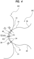
- a radius of curvature R1 of the arcuate convex surface 34 is larger than a radius of curvature R2 of the arcuate concave surface 36. Therefore, as shown in FIG. 4 , when the arcuate convex surface 34 of the Roots rotor 8C faces the arcuate concave surface 36 of the Roots rotor 9C, a crescent-shaped space 40 is formed between the arcuate convex surface 34 of the Roots rotor 8C and the arcuate concave surface 36 of the Roots rotor 9C.
- a clearance G1 between the arcuate convex surface 34 of the Roots rotor 8C and the arcuate concave surface 36 of the Roots rotor 9C is always larger than the clearance G2 between the involute side surface 31 of the Roots rotor 8C and the involute side surface 31 of the Roots rotor 9C.
- a clearance (or a distance) Glmin between an outermost point P1 on the arcuate convex surface 34 of the Roots rotor 8C and an innermost point P2 on the arcuate concave surface 36 of the Roots rotor 9C when the outermost point P1 and the innermost point P2 are closest to each other is 1.5 to 20 times the clearance G2 between the involute side surface 31 of the Roots rotor 8C and the involute side surface 31 of the Roots rotor 9C. If the clearance Glmin is too small, the particles may be strongly caught between the Roots rotors 8C and 9C. On the other hand, if the clearance Glmin is too large, the pumping efficiency will be lowered.
- FIG. 5 is a diagram showing the two Roots rotors 8C and 9C when rotating in the opposite directions.
- the clearance G2 between the involute side surface 31 of the Roots rotor 8C and the involute side surface 31 of the Roots rotor 9C is always constant. In other words, the clearance G2 is constant regardless of the rotation angle of the Roots rotors 8C and 9C.
- the involute side surfaces 31 of the Roots rotor 8C and the Roots rotor 9C face each other, and do not face the arcuate convex surface 34 and the arcuate concave surface 36.
- the arcuate convex surface 34 of the Roots rotor 8C faces the arcuate concave surface 36 of the Roots rotor 9C, and does not face the involute side surface 31 of the Roots rotor 9C.
- the arcuate convex surface 34 of the Roots rotor 9C faces the arcuate concave surface 36 of the Roots rotor 8C, and does not face the involute side surface 31 of the Roots rotor 8C.
- the involute side surface 31 is a surface that curves outward. Therefore, when the involute side surfaces 31 face each other, the clearance G2 is formed between one point on the involute side surface 31 of the Roots rotor 8C and one point on the involute side surface 31 of the Roots rotor 9C, as shown in FIG. 5 .
- a clearance between the Roots rotors 8C and 9C increases on both sides of the clearance G2. Due to such point contact (technically the Roots rotors 8C and 9C are in non-contact in reality) of the involute side surfaces 31, particles are less likely to be caught between the involute side surface 31 of the Roots rotor 8C and the involute side surface 31 of the Roots rotor 9C.
- the clearance G1 between the arcuate convex surface 34 of the Roots rotor 8C and the arcuate concave surface 36 of the Roots rotor 9C shown in FIG. 4 changes depending on the rotation angle of the Roots rotors 8C and 9C. As can be seen from the comparison between FIG. 4 and FIG. 5 , the clearance G1 is always larger than the clearance G2 regardless of the rotation angle of the Roots rotors 8C and 9C.
- the particles are less likely to be caught between the arcuate convex surface 34 of the Roots rotor 8C and the arcuate concave surface 36 of the Roots rotor 9C.
- the particles confined in the crescent-shaped space 40 between the arcuate convex surface 34 of the Roots rotor 8C and the arcuate concave surface 36 of the Roots rotor 9C are discharged from the crescent-shaped space 40 as the Roots rotors 8C and 9C rotate.
- the Roots rotors 8C and 9C can maintain smooth rotation.
- Roots rotors 8A to 8E and 9A to 9E of the embodiments described above are three-lobe Roots rotors each having three protrusions
- the present invention is not limited to the above embodiments.
- the present invention can be applied to two-lobe Roots rotor having two protrusions and multi-lobe Roots rotor having four or more protrusions.
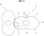
- FIG. 6 is a diagram illustrating an embodiment of two-lobe Roots rotors.
- each of the Roots rotors 51 and 52 has an involute side surface 31 having a shape of an involute curve, an arcuate convex surface 34 coupled to an outer end of the involute side surface 31, and an arcuate concave surface 36 coupled to an inner end of the involute side surface 31.
- a radius of curvature R3 of the arcuate convex surface 34 is larger than a radius of curvature R4 of the arcuate concave surface 36.
Landscapes
- Engineering & Computer Science (AREA)
- Mechanical Engineering (AREA)
- General Engineering & Computer Science (AREA)
- Applications Or Details Of Rotary Compressors (AREA)
- Rotary Pumps (AREA)
Abstract
Description
- The present invention relates to a vacuum pump, and more particularly to a vacuum pump suitable for use in evacuating a process gas used in manufacturing of semiconductor devices, liquid crystal panels, LEDs, solar cells, or the like.
- In process of manufacturing semiconductor devices, liquid crystal panels, LEDs, solar cells, etc., a process gas is introduced into a process chamber to perform a certain type of process, such as etching process or CVD process. The process gas that has been introduced into the process chamber is exhausted by a vacuum pump. Generally, the vacuum pump used in these manufacturing processes that require high cleanliness is so-called dry vacuum pump that does not use oil in its gas flow passage. One typical example of such a dry vacuum pump is a positive-displacement vacuum pump having a pair of Roots rotors in a rotor chamber which are rotated in opposite directions to deliver the gas.
- Patent document 1:
Japanese laid-open patent publication No. 1-077782 - A process gas may contain particles of by-products. Such particles flow into the vacuum pump along with the process gas. Moreover, depending on conditions in the vacuum pump (e.g., temperature, pressure), particles may be generated in the vacuum pump after the process gas flows into the vacuum pump. Most of the particles are discharged from the vacuum pump along with the process gas, but some of the particles remain in the rotor chamber and gradually accumulate in the rotor chamber. In particular, when convex and concave surfaces of two opposing Roots rotors are in surface contact (technically, the Roots rotors are in non-contact in reality), there is no place for the particles to escape. As a result, the particles are strongly sandwiched between the convex and concave surfaces of the Roots rotors, thus possibly hindering the rotation of the Roots rotors.
- Therefore, the present invention provides a vacuum pump capable of preventing particles from being caught between Roots rotors and capable of maintaining smooth rotation of the Roots rotors.
- In an embodiment, there is provided a vacuum pump comprising: a pump casing having at least one rotor chamber therein; and a first Roots rotor and a second Roots rotor arranged in parallel in the rotor chamber, wherein each of the first Roots rotor and the second Roots rotor has an involute side surface having a shape of an involute curve, an arcuate convex surface coupled to an outer end of the involute side surface, and an arcuate concave surface coupled to an inner end of the involute side surface, and a radius of curvature of the arcuate convex surface is larger than a radius of curvature of the arcuate concave surface.
- In an embodiment, a clearance between the involute side surface of the first Roots rotor and the involute side surface of the second Roots rotor is constant when the first Roots rotor and the second Roots rotor are rotating.
- In an embodiment, a clearance between the arcuate convex surface of the first Roots rotor and the arcuate concave surface of the second Roots rotor is larger than the clearance between the involute side surface of the first Roots rotor and the involute side surface of the second Roots rotor.
- In an embodiment, a clearance between an outermost point on the arcuate convex surface of the first Roots rotor and an innermost point on the arcuate concave surface of the second Roots rotor when the outermost point and the innermost point are closest to each other is 1.5 to 20 times the clearance between the involute side surface of the first Roots rotor and the involute side surface of the second Roots rotor.
- In an embodiment, a crescent-shaped space is formed between the arcuate convex surface of the first Roots rotor and the arcuate concave surface of the second Roots rotor when the arcuate convex surface of the first Roots rotor faces the arcuate concave surface of the second Roots rotor.
- In an embodiment, the involute side surface of the first Roots rotor faces only the involute side surface of the second Roots rotor, the arcuate convex surface of the first Roots rotor faces only the arcuate concave surface of the second Roots rotor, and the arcuate convex surface of the second Roots rotor faces only the arcuate concave surface of the first Roots rotor when the first Roots rotor and the second Roots rotor are rotating.
- The involute side surfaces of the first Roots rotor and the second Roots rotor face each other, and do not face the arcuate convex surface and the arcuate concave surface. Since a space expands on both sides of the clearance between the involute side surfaces, the involute side surfaces do not trap particles therebetween. Similarly, when the arcuate convex surface and the arcuate concave surface of the first Roots rotor and the second Roots rotor face each other, a space expands on both sides of a connection point of the arcuate convex surface and the involute side surface, and a space expands on both sides of a connection point of the arcuate concave surface and the involute side surface. Therefore, the first Roots rotor and the second Roots rotor do not trap particles therebetween.
- A large crescent-shaped space is formed between the arcuate convex surface of the first Roots rotor and the arcuate concave surface of the second Roots rotor. Therefore, the particles are less likely to be sandwiched between the arcuate convex surface of the first Roots rotor and the arcuate concave surface of the second Roots rotor. The particles confined in the crescent-shaped space are discharged from the crescent-shaped space as the Roots rotors rotate. As a result, the Roots rotors can maintain smooth rotation.
-
-
FIG. 1 is a cross-sectional view showing an embodiment of a vacuum pump apparatus; -
FIG. 2 is a cross-sectional view taken along a line A-A ofFIG. 1 ; -
FIG. 3 is an enlarged view of a Roots rotor; -
FIG. 4 is an enlarged view illustrating a clearance between Roots rotors; -
FIG. 5 is a diagram showing two Roots rotors when rotating in opposite directions; and -
FIG. 6 is a diagram illustrating an embodiment of two-lobe Roots rotors. - Embodiments of the present invention will be described below with reference to the drawings.
FIG. 1 is a sectional view showing an embodiment of a vacuum pump apparatus, andFIG. 2 is a sectional view taken along line AA inFIG. 1 . The vacuum pump apparatus of the embodiment described below is a positive displacement vacuum pump apparatus. In particular, the vacuum pump apparatus shown inFIGS. 1 and2 is a so-called dry vacuum pump apparatus that does not use oil in its gas flow passage. Since vaporized oil does not flow to an upstream side, the dry vacuum pump apparatus can be used in semiconductor device manufacturing apparatus that requires high cleanliness. - As shown in
FIG. 1 , the vacuum pump apparatus includes avacuum pump 1 and anelectric motor 2 that drives thevacuum pump 1. Thevacuum pump 1 of this embodiment is a multistage vacuum pump. Specifically, thevacuum pump 1 includes apump casing 6 having a plurality ofrotor chambers 5A to 5E therein, a plurality ofRoots rotors 8A to 8E, 9A to 9E arranged in therotor chambers 5A to 5E, respectively, and a pair ofrotational shafts Roots rotors 8A to 8E and theRoots rotors 9A to 9E. In one embodiment, thevacuum pump 1 may be a single-stage vacuum pump having single-stage Roots rotors arranged in one rotor chamber. - Although only the
Roots rotors 8A to 8E and therotational shaft 11 are depicted inFIG. 1 , theRoots rotors 8A to 8E and theRoots rotors 9A to 9E are arranged in parallel in thepump casing 6, and therotational shaft 11 and therotational shaft 12 are arranged in parallel.FIG. 2 shows theRoots rotor 8C and theRoots rotor 9C arranged in parallel with each other. Although not shown, theRoots rotors Roots rotors pump casing 6. TheRoots rotors 8A to 8E are supported by therotational shaft 11, and theRoots rotors 9A to 9E are supported by therotational shaft 12. - The
Roots rotors 8A to 8E and theRoots rotors 9A to 9E are not in contact with each other, and theRoots rotors 8A to 8E and 9A to 9E are not in contact with an inner surface of thepump casing 6. Therefore, theRoots rotors 8A to 8E, 9A to 9E can rotate smoothly in thepump casing 6 without using lubricating oil. - The
Roots rotors 8A to 8E and therotational shaft 11 may be an integral structure. Similarly, theRoots rotors 9A to 9E and therotational shaft 12 may be an integral structure. Theelectric motor 2 is coupled to one of therotational shafts electric motors 2 may be coupled to therotational shafts - As shown in
FIG. 1 , theRoots rotors 8A to 8E, 9A to 9E and therotor chambers 5A to 5E are arranged along a gas transfer direction. Specifically, theRoots rotors rotor chamber 5A are located at the most upstream side in the gas transfer direction in thepump casing 6. TheRoots rotors rotor chamber 5B are located downstream of theRoots rotors rotor chamber 5A. TheRoots rotors rotor chamber 5C are located downstream of theRoots rotors rotor chamber 5B. TheRoots rotors rotor chamber 5D are located downstream of theRoots rotors rotor chamber 5C. TheRoots rotors rotor chamber 5E are located downstream of theRoots rotors rotor chamber 5D. TheRoots rotors rotor chamber 5E are located at the most downstream side in the gas transfer direction in thepump casing 6. - The
pump casing 6 has agas inlet 14A and agas outlet 15A that communicate with therotor chamber 5A, agas inlet 14B and agas outlet 15B that communicate with therotor chamber 5B, agas inlet 14C and agas outlet 15C that communicate with therotor chamber 5C, agas inlet 14D and agas outlet 15D that communicate with therotor chamber 5D, and agas inlet 14E and agas outlet 15E that communicate with therotor chamber 5E. - The
gas inlet 14A is coupled to a chamber (not shown) filled with a gas to be delivered. In one example, thegas inlet 14A is coupled to a process chamber of a semiconductor-device manufacturing apparatus, and thevacuum pump 1 is used to evacuate a process gas that has been introduced into the process chamber. Thegas outlet 15A communicates with thegas inlet 14B via a fluid passage (not shown), thegas outlet 15B communicates with thegas inlet 14C via a fluid passage (not shown), thegas outlet 15C communicates with thegas inlet 14D via a fluid passage (not shown), and thegas outlet 15D communicates with thegas inlet 14E via a fluid passage (not shown). - The
vacuum pump 1 further includes agear housing 16 located outwardly of aside wall 6A of thepump casing 6. A pair ofgears 20 that mesh with each other are arranged in thegear housing 16. InFIG. 1 , only onegear 20 is depicted. These gears 20 are fixed to therotational shafts electric motor 2 is rotated by a motor driver (not shown), and one of therotational shafts electric motor 2 is coupled is rotated by theelectric motor 2. This rotation is transmitted via thegears 20 to other one of therotational shafts electric motor 2 is not coupled to thereby rotate the other rotational shaft in the opposite direction. - The
rotational shafts bearings 17 held on theside wall 6A of thepump casing 6 andbearings 18 held onother side wall 6B of thepump casing 6. Theelectric motor 2 includes amotor housing 22 located outwardly of theside wall 6B of thepump casing 6, and amotor rotor 2A and amotor stator 2B arranged in themotor housing 22. - In one embodiment, a pair of
electric motors 2 coupled to therotational shafts electric motors 2 are synchronously rotated in opposite directions by a motor driver (not shown), so that therotational shafts Roots rotors 8A to 8E and theRoots rotors 9A to 9E are synchronously rotated in the opposite directions, as shown inFIG. 2 . The role of thegears 20 in this case is to prevent out of the synchronized rotation of the Roots rotors due to a sudden external cause. - When the
electric motor 2 rotates theRoots rotors 8A to 8E, 9A to 9E, gas is sucked into therotor chamber 5A through thegas inlet 14A. The gas is compressed by theRoots rotors 8A to 8E, 9A to 9E sequentially in therotor chambers 5A to 5E, and is discharged from thepump casing 6 through thegas outlet 15E. - In this embodiment, the
Roots rotors 8A to 8E and 9A to 9E have the same contour. In one embodiment, the contours of the Roots rotors of different stages may be different. TheRoots rotor 8C will be explained below.FIG. 3 is an enlarged view of theRoots rotor 8C. As shown inFIG. 3 , theRoots rotor 8C includes aninvolute side surface 31 having a shape of an involute curve, an arcuateconvex surface 34 coupled to an outer end of theinvolute side surface 31, and an arcuateconcave surface 36 coupled to an inner end of theinvolute side surface 31. TheRoots rotor 8C is a so-called three-lobe Roots rotor having three protrusions. Therefore, theRoots rotor 8C has three arcuateconvex surfaces 34, six involute side surfaces 31, and three arcuate concave surfaces 36. The three arcuateconvex surfaces 34 are coupled to the outer ends of the six involute side surfaces 31, and the three arcuateconcave surfaces 36 are coupled to the inner ends of the sixinvolute sides 31. TheRoots rotor 9C facing theRoots rotor 8C has the same shape as theRoots rotor 8C. - A radius of curvature R1 of the arcuate
convex surface 34 is larger than a radius of curvature R2 of the arcuateconcave surface 36. Therefore, as shown inFIG. 4 , when the arcuateconvex surface 34 of theRoots rotor 8C faces the arcuateconcave surface 36 of theRoots rotor 9C, a crescent-shapedspace 40 is formed between the arcuateconvex surface 34 of theRoots rotor 8C and the arcuateconcave surface 36 of theRoots rotor 9C. - When the arcuate
convex surface 34 and the arcuateconcave surface 36 of theRoots rotors arcuate convexity surface 34 and theinvolute side surface 31, and a space expands on both sides of a connection point of the arcuateconcave surface 36 and theinvolute side surface 31. With these configurations, theRoots rotor 8C and theRoots rotor 9C do not bite particles. The crescent-shapedspace 40 formed next to the involute side surface 31 functions as a temporary escape space for the particles. Specifically, as theRoots rotors space 40, and are discharged from the crescent-shapedspace 40 as theRoots rotors - When a phase in which the involute side surfaces 31 face each other is changed into a phase in which the arcuate
convex surface 34 and the arcuateconcave surface 36 face each other, two clearances G2 exist on both sides of the crescent-shapedspace 40, as shown inFIG. 4 . Thereafter, as the Roots rotors 8C, 9C rotate, only one clearance G2 exists. Such movement of the Roots rotors 8C, 9C allows the particles to be easily discharged. - In
FIG. 4 , when theRoots rotor 8C and theRoots rotor 9C are rotating, a clearance G1 between the arcuateconvex surface 34 of theRoots rotor 8C and the arcuateconcave surface 36 of theRoots rotor 9C is always larger than the clearance G2 between theinvolute side surface 31 of theRoots rotor 8C and theinvolute side surface 31 of theRoots rotor 9C. In particular, a clearance (or a distance) Glmin between an outermost point P1 on the arcuateconvex surface 34 of theRoots rotor 8C and an innermost point P2 on the arcuateconcave surface 36 of theRoots rotor 9C when the outermost point P1 and the innermost point P2 are closest to each other is 1.5 to 20 times the clearance G2 between theinvolute side surface 31 of theRoots rotor 8C and theinvolute side surface 31 of theRoots rotor 9C. If the clearance Glmin is too small, the particles may be strongly caught between theRoots rotors -
FIG. 5 is a diagram showing the twoRoots rotors FIG. 5 , when theRoots rotor 8C and theRoots rotor 9C are rotating, the clearance G2 between theinvolute side surface 31 of theRoots rotor 8C and theinvolute side surface 31 of theRoots rotor 9C is always constant. In other words, the clearance G2 is constant regardless of the rotation angle of theRoots rotors - The involute side surfaces 31 of the
Roots rotor 8C and theRoots rotor 9C face each other, and do not face the arcuateconvex surface 34 and the arcuateconcave surface 36. In contrast, the arcuateconvex surface 34 of theRoots rotor 8C faces the arcuateconcave surface 36 of theRoots rotor 9C, and does not face theinvolute side surface 31 of theRoots rotor 9C. Similarly, the arcuateconvex surface 34 of theRoots rotor 9C faces the arcuateconcave surface 36 of theRoots rotor 8C, and does not face theinvolute side surface 31 of theRoots rotor 8C. - The
involute side surface 31 is a surface that curves outward. Therefore, when the involute side surfaces 31 face each other, the clearance G2 is formed between one point on theinvolute side surface 31 of theRoots rotor 8C and one point on theinvolute side surface 31 of theRoots rotor 9C, as shown inFIG. 5 . A clearance between theRoots rotors Roots rotors involute side surface 31 of theRoots rotor 8C and theinvolute side surface 31 of theRoots rotor 9C. - The clearance G1 between the arcuate
convex surface 34 of theRoots rotor 8C and the arcuateconcave surface 36 of theRoots rotor 9C shown inFIG. 4 changes depending on the rotation angle of theRoots rotors FIG. 4 andFIG. 5 , the clearance G1 is always larger than the clearance G2 regardless of the rotation angle of theRoots rotors - With such configurations, the particles are less likely to be caught between the arcuate
convex surface 34 of theRoots rotor 8C and the arcuateconcave surface 36 of theRoots rotor 9C. The particles confined in the crescent-shapedspace 40 between the arcuateconvex surface 34 of theRoots rotor 8C and the arcuateconcave surface 36 of theRoots rotor 9C are discharged from the crescent-shapedspace 40 as theRoots rotors Roots rotors - Although the
Roots rotors 8A to 8E and 9A to 9E of the embodiments described above are three-lobe Roots rotors each having three protrusions, the present invention is not limited to the above embodiments. The present invention can be applied to two-lobe Roots rotor having two protrusions and multi-lobe Roots rotor having four or more protrusions. - For example,
FIG. 6 is a diagram illustrating an embodiment of two-lobe Roots rotors. Also in this embodiment, each of theRoots rotors involute side surface 31 having a shape of an involute curve, an arcuateconvex surface 34 coupled to an outer end of theinvolute side surface 31, and an arcuateconcave surface 36 coupled to an inner end of theinvolute side surface 31. A radius of curvature R3 of the arcuateconvex surface 34 is larger than a radius of curvature R4 of the arcuateconcave surface 36. Configurations of the two-lobe Roots rotors FIGS. 1 to 5 , and redundant explanations will be omitted. - The previous description of embodiments is provided to enable a person skilled in the art to make and use the present invention. Moreover, various modifications to these embodiments will be readily apparent to those skilled in the art, and the generic principles and specific examples defined herein may be applied to other embodiments. Therefore, the present invention is not intended to be limited to the embodiments described herein but is to be accorded the widest scope as defined by limitation of the claims.
Claims (6)
- A vacuum pump comprising:a pump casing having at least one rotor chamber therein; anda first Roots rotor and a second Roots rotor arranged in parallel in the rotor chamber,wherein each of the first Roots rotor and the second Roots rotor has an involute side surface having a shape of an involute curve, an arcuate convex surface coupled to an outer end of the involute side surface, and an arcuate concave surface coupled to an inner end of the involute side surface, anda radius of curvature of the arcuate convex surface is larger than a radius of curvature of the arcuate concave surface.
- The vacuum pump according to claim 1, wherein a clearance between the involute side surface of the first Roots rotor and the involute side surface of the second Roots rotor is constant when the first Roots rotor and the second Roots rotor are rotating.
- The vacuum pump according to claim 2, wherein a clearance between the arcuate convex surface of the first Roots rotor and the arcuate concave surface of the second Roots rotor is larger than the clearance between the involute side surface of the first Roots rotor and the involute side surface of the second Roots rotor.
- The vacuum pump according to claim 3, wherein a clearance between an outermost point on the arcuate convex surface of the first Roots rotor and an innermost point on the arcuate concave surface of the second Roots rotor when the outermost point and the innermost point are closest to each other is 1.5 to 20 times the clearance between the involute side surface of the first Roots rotor and the involute side surface of the second Roots rotor.
- The vacuum pump according to claim 1, wherein a crescent-shaped space is formed between the arcuate convex surface of the first Roots rotor and the arcuate concave surface of the second Roots rotor when the arcuate convex surface of the first Roots rotor faces the arcuate concave surface of the second Roots rotor.
- The vacuum pump according to claim 1, wherein the involute side surface of the first Roots rotor faces only the involute side surface of the second Roots rotor, the arcuate convex surface of the first Roots rotor faces only the arcuate concave surface of the second Roots rotor, and the arcuate convex surface of the second Roots rotor faces only the arcuate concave surface of the first Roots rotor when the first Roots rotor and the second Roots rotor are rotating.
Applications Claiming Priority (1)
| Application Number | Priority Date | Filing Date | Title |
|---|---|---|---|
| JP2023018621A JP2024113550A (en) | 2023-02-09 | 2023-02-09 | Vacuum pump |
Publications (1)
| Publication Number | Publication Date |
|---|---|
| EP4417787A1 true EP4417787A1 (en) | 2024-08-21 |
Family
ID=89854566
Family Applications (1)
| Application Number | Title | Priority Date | Filing Date |
|---|---|---|---|
| EP24156227.1A Pending EP4417787A1 (en) | 2023-02-09 | 2024-02-07 | Roots type vacuum pump |
Country Status (5)
| Country | Link |
|---|---|
| EP (1) | EP4417787A1 (en) |
| JP (1) | JP2024113550A (en) |
| KR (1) | KR20240124812A (en) |
| CN (1) | CN118462578A (en) |
| TW (1) | TW202438769A (en) |
Citations (4)
| Publication number | Priority date | Publication date | Assignee | Title |
|---|---|---|---|---|
| JPS6477782A (en) | 1987-09-19 | 1989-03-23 | Ebara Corp | Rotary machine of roots type |
| US5152684A (en) * | 1990-08-27 | 1992-10-06 | Leybold Aktiengesellschaft | Rotor profile for a roots vacuum pump |
| CN203892187U (en) * | 2014-06-20 | 2014-10-22 | 淄博景曜真空设备有限公司 | Vertical Roots dry vacuum pump |
| CN111271284A (en) * | 2020-03-16 | 2020-06-12 | 江阴全玉节能环保真空设备制造有限公司 | Three-blade rotor assembly of roots vacuum pump |
-
2023
- 2023-02-09 JP JP2023018621A patent/JP2024113550A/en active Pending
-
2024
- 2024-02-02 KR KR1020240016395A patent/KR20240124812A/en active Pending
- 2024-02-04 CN CN202410156186.3A patent/CN118462578A/en active Pending
- 2024-02-05 TW TW113104506A patent/TW202438769A/en unknown
- 2024-02-07 EP EP24156227.1A patent/EP4417787A1/en active Pending
Patent Citations (4)
| Publication number | Priority date | Publication date | Assignee | Title |
|---|---|---|---|---|
| JPS6477782A (en) | 1987-09-19 | 1989-03-23 | Ebara Corp | Rotary machine of roots type |
| US5152684A (en) * | 1990-08-27 | 1992-10-06 | Leybold Aktiengesellschaft | Rotor profile for a roots vacuum pump |
| CN203892187U (en) * | 2014-06-20 | 2014-10-22 | 淄博景曜真空设备有限公司 | Vertical Roots dry vacuum pump |
| CN111271284A (en) * | 2020-03-16 | 2020-06-12 | 江阴全玉节能环保真空设备制造有限公司 | Three-blade rotor assembly of roots vacuum pump |
Also Published As
| Publication number | Publication date |
|---|---|
| CN118462578A (en) | 2024-08-09 |
| KR20240124812A (en) | 2024-08-19 |
| TW202438769A (en) | 2024-10-01 |
| JP2024113550A (en) | 2024-08-22 |
Similar Documents
| Publication | Publication Date | Title |
|---|---|---|
| JP5073754B2 (en) | Multistage dry pump | |
| KR101351667B1 (en) | Vacuum pump | |
| JPH0874765A (en) | Stepless compression screw vacuum pump | |
| JP2003097480A (en) | Screw type vacuum pump | |
| EP1813818A2 (en) | Evacuating apparatus | |
| EP4682381A1 (en) | Vacuum pump | |
| JPH0932766A (en) | Screw fluid machine and screw gear | |
| CN118462578A (en) | Vacuum pump | |
| JP2003161277A (en) | Multi-stage dry vacuum pump | |
| EP4534846A2 (en) | Vacuum pump and method of determining shape of roots rotor | |
| JP7860745B2 (en) | vacuum pump | |
| JP4839443B2 (en) | Screw vacuum pump | |
| EP4239197A1 (en) | Vacuum pump | |
| JP2005195027A (en) | Screw fluid machine and screw gear | |
| JP2007263122A (en) | Vacuum exhaust device | |
| US8075288B2 (en) | Screw pump and pumping arrangement | |
| JP2002174174A (en) | Vacuum exhaust device | |
| JP2007298043A (en) | Vacuum exhaust device | |
| JP2004293377A (en) | Multi-stage dry pump | |
| JP6653732B2 (en) | Vacuum pump unit | |
| JPH11210655A (en) | Vacuum pump | |
| JP3596063B2 (en) | Scroll compressor | |
| KR101150971B1 (en) | Screw rotor type vaccum pump | |
| JP2005256845A (en) | Vacuum exhaust device | |
| JP2007263121A (en) | Vacuum exhaust device |
Legal Events
| Date | Code | Title | Description |
|---|---|---|---|
| PUAI | Public reference made under article 153(3) epc to a published international application that has entered the european phase |
Free format text: ORIGINAL CODE: 0009012 |
|
| STAA | Information on the status of an ep patent application or granted ep patent |
Free format text: STATUS: THE APPLICATION HAS BEEN PUBLISHED |
|
| AK | Designated contracting states |
Kind code of ref document: A1 Designated state(s): AL AT BE BG CH CY CZ DE DK EE ES FI FR GB GR HR HU IE IS IT LI LT LU LV MC ME MK MT NL NO PL PT RO RS SE SI SK SM TR |
|
| STAA | Information on the status of an ep patent application or granted ep patent |
Free format text: STATUS: REQUEST FOR EXAMINATION WAS MADE |
|
| 17P | Request for examination filed |
Effective date: 20250124 |
|
| GRAP | Despatch of communication of intention to grant a patent |
Free format text: ORIGINAL CODE: EPIDOSNIGR1 |
|
| STAA | Information on the status of an ep patent application or granted ep patent |
Free format text: STATUS: GRANT OF PATENT IS INTENDED |
|
| INTG | Intention to grant announced |
Effective date: 20260326 |