EP4417757A1 - Image display system, remote operation assistance system, and image display method - Google Patents
Image display system, remote operation assistance system, and image display method Download PDFInfo
- Publication number
- EP4417757A1 EP4417757A1 EP22900966.7A EP22900966A EP4417757A1 EP 4417757 A1 EP4417757 A1 EP 4417757A1 EP 22900966 A EP22900966 A EP 22900966A EP 4417757 A1 EP4417757 A1 EP 4417757A1
- Authority
- EP
- European Patent Office
- Prior art keywords
- image
- index
- work
- index point
- output
- Prior art date
- Legal status (The legal status is an assumption and is not a legal conclusion. Google has not performed a legal analysis and makes no representation as to the accuracy of the status listed.)
- Pending
Links
- 238000000034 method Methods 0.000 title claims description 15
- 230000007246 mechanism Effects 0.000 claims abstract description 121
- 238000006073 displacement reaction Methods 0.000 claims description 21
- 230000008859 change Effects 0.000 claims description 13
- 230000033001 locomotion Effects 0.000 claims description 7
- 239000002131 composite material Substances 0.000 claims description 4
- 230000006870 function Effects 0.000 description 27
- 238000010586 diagram Methods 0.000 description 25
- 238000012545 processing Methods 0.000 description 25
- 238000004891 communication Methods 0.000 description 20
- 230000008569 process Effects 0.000 description 11
- 238000012790 confirmation Methods 0.000 description 8
- 239000000470 constituent Substances 0.000 description 5
- 239000004576 sand Substances 0.000 description 5
- 230000005540 biological transmission Effects 0.000 description 4
- 239000010720 hydraulic oil Substances 0.000 description 3
- 230000004044 response Effects 0.000 description 3
- 230000009471 action Effects 0.000 description 2
- 238000009412 basement excavation Methods 0.000 description 2
- 230000008901 benefit Effects 0.000 description 2
- 238000000605 extraction Methods 0.000 description 2
- 238000010191 image analysis Methods 0.000 description 2
- 239000003086 colorant Substances 0.000 description 1
- 238000010276 construction Methods 0.000 description 1
- 238000007796 conventional method Methods 0.000 description 1
- 238000001514 detection method Methods 0.000 description 1
- 230000000694 effects Effects 0.000 description 1
- 230000003028 elevating effect Effects 0.000 description 1
- 239000000463 material Substances 0.000 description 1
- 201000003152 motion sickness Diseases 0.000 description 1
- 230000009467 reduction Effects 0.000 description 1
- 238000012876 topography Methods 0.000 description 1
Images






Classifications
-
- E—FIXED CONSTRUCTIONS
- E02—HYDRAULIC ENGINEERING; FOUNDATIONS; SOIL SHIFTING
- E02F—DREDGING; SOIL-SHIFTING
- E02F9/00—Component parts of dredgers or soil-shifting machines, not restricted to one of the kinds covered by groups E02F3/00 - E02F7/00
- E02F9/26—Indicating devices
-
- E—FIXED CONSTRUCTIONS
- E02—HYDRAULIC ENGINEERING; FOUNDATIONS; SOIL SHIFTING
- E02F—DREDGING; SOIL-SHIFTING
- E02F9/00—Component parts of dredgers or soil-shifting machines, not restricted to one of the kinds covered by groups E02F3/00 - E02F7/00
- E02F9/20—Drives; Control devices
- E02F9/2025—Particular purposes of control systems not otherwise provided for
- E02F9/205—Remotely operated machines, e.g. unmanned vehicles
-
- E—FIXED CONSTRUCTIONS
- E02—HYDRAULIC ENGINEERING; FOUNDATIONS; SOIL SHIFTING
- E02F—DREDGING; SOIL-SHIFTING
- E02F9/00—Component parts of dredgers or soil-shifting machines, not restricted to one of the kinds covered by groups E02F3/00 - E02F7/00
- E02F9/26—Indicating devices
- E02F9/261—Surveying the work-site to be treated
-
- E—FIXED CONSTRUCTIONS
- E02—HYDRAULIC ENGINEERING; FOUNDATIONS; SOIL SHIFTING
- E02F—DREDGING; SOIL-SHIFTING
- E02F9/00—Component parts of dredgers or soil-shifting machines, not restricted to one of the kinds covered by groups E02F3/00 - E02F7/00
- E02F9/26—Indicating devices
- E02F9/264—Sensors and their calibration for indicating the position of the work tool
Definitions
- the present invention relates to a technique for assisting an operator's remote operation of a work machine such as a hydraulic excavator.
- Patent Literature 1 Japanese Patent No. 6777375
- the position of the work apparatus is represented by an image formed along the topography according to the conventional technique. Therefore, since unnecessary position information other than a predetermined part of the work apparatus is also displayed at the same time, it can be difficult to grasp the position of the work apparatus with respect to the work object, which can make it difficult to work efficiently.
- an object of the present invention is to provide a system and the like that can improve the accuracy with which an operator recognizes the positional relationship between a work mechanism constituting a work machine and an object present around the work machine.
- An image display system is an image display system, wherein on a work environment image representing a situation of a work mechanism constituting a work machine and an object present around the work machine, an index image indicating a second index point resulting from a first index point of the work mechanism being projected onto a surface of the object is superimposed and output to an output interface of a remote operation device for remotely operating the work machine.
- an operator is allowed to grasp the position of the work mechanism constituting the work machine and the position of the second index point on the surface of the object through the work environment image and the index image superimposed thereon that are output to the output interface of the remote operation device.
- the second index point is the result of the first index point being projected onto the surface of the object, and is not along the surface shape of the object. This prevents the operator from being provided with position information on unnecessary parts of the work mechanism other than the first index point, and improves the accuracy with which the operator recognizes the positional relationship between the work mechanism and the object.
- An image display composite system shown in FIG. 1 is composed of an image display system 10, a remote operation device 20, and/or a work machine 40 to be remotely operated by the remote operation device 20.
- the image display system 10, the remote operation device 20, and the work machine 40 are configured to be able to communicate with each other over a network.
- An intercommunication network between the image display system 10 and the remote operation device 20 may be identical to or different from an intercommunication network between the image display system 10 and the work machine 40.
- the image display system 10 is implemented by a computer that is present separately from the remote operation device 20 and the work machine 40, and comprises a database 102, a communication function element 121, and an image processing function element 122.
- the database 102 stores and holds captured image data and the like.
- the database 102 may be implemented by a database server that can communicate with the image display system 10.
- the function elements are implemented by an arithmetic processing device (e.g., a single-core processor and/or a multi-core processor or a processor core constituting the same), read necessary data and software from a storage device such as a memory, and execute later-described arithmetic processing according to the software on the data.
- the remote operation device 20 comprises a remote control device 200, a remote input interface 210, a remote output interface 220, and remote wireless communication equipment 224.
- the remote control device 200 is implemented by an arithmetic processing device (e.g., a single-core processor and/or a multi-core processor or a processor core constituting the same), reads necessary data and software from a storage device such as a memory, and executes arithmetic processing according to the software on the data.
- arithmetic processing device e.g., a single-core processor and/or a multi-core processor or a processor core constituting the same
- the remote input interface 210 comprises a remote operation mechanism 211.
- the remote output interface 220 comprises a remote image output device 221.
- the remote operation mechanism 211 includes a travel operation device, a turning operation device, a boom operation device, an arm operation device, and a bucket operation device.
- Each of the operation devices has an operation lever which receives a pivot operation.
- the operation lever of the travel operation device (travel lever) is operated to move a lower traveling body 410 of the work machine 40.
- the travel lever may also function as a travel pedal.
- a travel pedal which is fixed to a base portion or a lower end portion of the travel lever may be provided.
- the operation lever of the turning operation device (turn lever) is operated to move a hydraulic turning motor constituting a turning mechanism 430 of the work machine 40.
- the operation lever of the boom operation device (boom lever) is operated to move a boom cylinder 442 of the work machine 40.
- the operation lever of the arm operation device (arm lever) is operated to move an arm cylinder 444 of the work machine 40.
- the operation lever of the bucket operation device (bucket lever) is operated to move a bucket cylinder 4
- the operation levers constituting the remote operation mechanism 211 are disposed around a seat St for an operator to sit on.
- the seat St is in the form of a high back chair with armrests, but may be a seat in any form on which the operator can sit, for example, a form such as a low back chair with no headrest, or a form such as a chair with no backrest.
- a pair of left and right travel levers 2110 corresponding to left and right crawlers are disposed side by side on the left side and right side in front of the seat St.
- One operation lever may also function as a plurality of operation levers.
- a left-side operation lever 2111 provided in front of a left-side frame of the seat St shown in FIG. 2 may function as an arm lever when the left-side operation lever 2111 is operated in a front-rear direction, and also function as a turn lever when the left-side operation lever 2111 is operated in a left-right direction.
- a right-side operation lever 2112 provided in front of a right-side frame of the seat St shown in FIG.
- a lever pattern may be changed in any manner according to an operation instruction from the operator.
- the remote image output device 221 is composed of a central remote image output device 2210, a left-side remote image output device 2211, and a right-side remote image output device 2212 disposed in front, on the diagonally front left side, and the diagonally front right side, respectively, of the seat St, each remote image output device having a substantially rectangular screen.
- the respective screens (image display areas) of the central remote image output device 2210, the left-side remote image output device 2211, and the right-side remote image output device 2212 may have the same shape and size, or different shapes and sizes.
- the right edge of the left-side remote image output device 2211 is adj acent to the left edge of the central remote image output device 2210 such that the screen of the central remote image output device 2210 and the screen of the left-side remote image output device 2211 form an inclination angle ⁇ 1 (e.g., 120° ⁇ ⁇ 1 ⁇ 150°).
- the left edge of the right-side remote image output device 2212 is adj acent to the right edge of the central remote image output device 2210 such that the screen of the central remote image output device 2210 and the screen of the right-side remote image output device 2212 form an inclination angle ⁇ 2 (e.g., 120° ⁇ ⁇ 2 ⁇ 150°).
- the inclination angles ⁇ 1 and ⁇ 2 may be the same, or different from each other.
- the respective screens of the central remote image output device 2210, the left-side remote image output device 2211, and the right-side remote image output device 2212 may be parallel to a vertical direction, or inclined with respect to the vertical direction.
- At least one image output device of the central remote image output device 2210, the left-side remote image output device 2211, and the right-side remote image output device 2212 may be composed of a plurality of split image output devices.
- the central remote image output device 2210 may be composed of a pair of image output devices which have substantially rectangular screens and are disposed adjacent to each other in the up-down direction.
- the remote image output device 221 may be composed of a single image output device that is curved or bent so as to surround the seat St.
- the single image output device may be implemented by, for example, the central remote image output device 2210.
- the remote image output device 221 may be composed of two image output devices (e.g., the central remote image output device 2210 and the left-side remote image output device 2211 or the right-side remote image output device 2212).
- the work machine 40 comprises an actual machine control device 400, an actual machine input interface 41, an actual machine output interface 42, actual machine wireless communication equipment 422, and a work mechanism 440.
- the actual machine control device 400 is implemented by an arithmetic processing device (a single-core processor or a multi-core processor or a processor core constituting the same), reads necessary data and software from a storage device such as a memory, and executes arithmetic processing according to the software on the data.
- the work machine 40 is, for example, a crawler excavator (a construction machine), and as shown in FIG. 3 , comprises a crawler-type lower traveling body 410, and an upper turning body 420 mounted on the lower traveling body 410 via a turning mechanism 430 in a turnable manner.
- a cab 424 (driver's cabin) is provided on the front left side of the upper turning body 420.
- the work mechanism 440 is provided at the front center of the upper turning body 420.
- the actual machine input interface 41 comprises an actual machine operating mechanism 411, an actual machine image capturing device 412, an actual machine distance measuring device 414, and an actual machine sensor group 416.
- the actual machine operating mechanism 411 comprises a plurality of operation levers disposed in the same manner as the remote operation mechanism 211 around the seat installed in the cab 424.
- the cab 424 is provided with a driving mechanism or a robot that receives a signal corresponding to an operation mode of the remote operation levers, and moves the actual machine operation levers based on the received signal.
- the actual machine image capturing device 412 is installed, for example, in the cab 424, and captures an image of the environment including at least a portion (e.g., an attachment 445) of the work mechanism 440 through a front window.
- the actual machine distance measuring device 414 is a device for measuring the real space distance to an object present around the work machine 40 and therefore its real space position, and is implemented by, for example, LiDAR and a TOF sensor.
- the actual machine sensor group 416 is composed of various sensors for measuring the motion state of the work machine 40, such as a turning angle sensor for measuring the turning angle of the upper turning body 420 with respect to the lower traveling body 410, and a posture angle sensor for measuring the posture angle representing the posture of the work mechanism 440.
- the actual machine output interface 42 comprises the actual machine wireless communication equipment 422.
- the work mechanism 440 as a work mechanism comprises a boom 441 attached to the upper turning body 420 in an elevatable manner, an arm 443 pivotably connected to a tip of the boom 441, and an attachment 445 (e.g., a bucket) pivotably connected to a tip of the arm 443.
- the work mechanism 440 are equipped with the boom cylinder 442, the arm cylinder 444, and the bucket cylinder 446, each implemented by an extendable hydraulic cylinder.
- the boom cylinder 442 is interposed between the boom 441 and the upper turning body 420 such that the boom cylinder 442 is supplied with hydraulic oil to extend and shorten, thereby pivoting the boom 441 in an elevating direction.
- the arm cylinder 444 is interposed between the arm 443 and the boom 441 such that the arm cylinder 444 is supplied with hydraulic oil to extend and shorten, thereby pivoting the arm 443 around a horizontal axis with respect to the boom 441.
- the bucket cylinder 446 is interposed between the attachment 445 and the arm 443 such that the bucket cylinder 446 is supplied with hydraulic oil to extend and shorten, thereby pivoting the attachment 445 around a horizontal axis with respect to the arm 443.
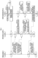
- FIG. 4 is a flowchart illustrating the image display system having the above-described configuration and functions of the image display system.
- the blocks "C•” are used to simplify the description, mean the transmission and/or reception of data, and mean a conditional branch in which the processing in the branch direction is executed under the condition of having transmitted and/or received the data.
- the flowchart is repeated for each control period, and after the process has reached "END", it returns to "START" and executes the subsequent processing.
- the remote operation device 20 it is determined whether there is an environment confirmation request operation (a second specified operation) performed by the operator through the remote input interface 210 ( FIG. 4 /STEP 210).
- the "environment confirmation request” is an operation, such as a tap on the remote input interface 210, for the operator to instruct the work machine 40, which the operator intends to remotely operate, to perform an environment confirmation request operation. If the determination result is negative ( FIG. 4 /STEP 210 .. NO), the process returns to START. On the other hand, if the determination result is affirmative ( FIG. 4 /STEP 210 .. YES), an environment confirmation request is transmitted to the image display system 10 through the remote wireless communication equipment 224 ( FIG. 4 /STEP 211).
- the environment confirmation request when the environment confirmation request is received, the environment confirmation request is transmitted to the corresponding work machine 40 by the communication function element 121 ( FIG. 4 /C10).
- the environment confirmation request may be transmitted to the work machine 40 not via the image display system 10.
- a captured image of a work object Obj (e.g., the ground, earth and sand, materials, and/or structures that are present around the work machine 40) is acquired by the actual machine image capturing device 412, a three-dimensional image of the work object Obj is also acquired by the actual machine distance measuring device 414, and three-dimensional image data representing the three-dimensional image is transmitted to the image display system 10 through the actual machine wireless communication equipment 422 ( FIG. 4 /STEP 410).
- the three-dimensional image is an image having the direction of and the distance to the work object Obj or the real space position of the work object Obj acquired through the actual machine distance measuring device 414.
- the "real space position" is defined by coordinate values in a real space coordinate system (e.g., latitude, longitude, and altitude) or coordinate values in an actual machine coordinate system (a coordinate system whose position or posture is fixed relative to the work machine 40).
- a real space coordinate system e.g., latitude, longitude, and altitude
- coordinate values in an actual machine coordinate system a coordinate system whose position or posture is fixed relative to the work machine 40.
- the three-dimensional image data may be acquired and transmitted as a combination of data of the captured image acquired through the actual machine image capturing device 412 or a model image equivalent thereto and data of the distance or real space position acquired through the actual machine distance measuring device 414, which are separate data.
- the captured image in which at least the work object Obj appears may not be acquired through the actual machine image capturing device 412, but through an image capturing device installed around the work machine 40, an image capturing device mounted on an unmanned drone, and/or an image capturing device of equipment carried by a site worker.
- the distance or real space position which is the pixel value of the three-dimensional image, may be acquired through a distance measuring device installed around the work machine 40 and/or a distance measuring device mounted on an unmanned drone.
- a captured image and a three-dimensional image of the work object Obj may be acquired through a stereo camera (a pair of left and right actual machine image capturing devices 412) mounted on the work machine 40.
- work environment image data corresponding to the three-dimensional image data is transmitted to the remote operation device 20 by the image processing function element 122 ( FIG. 4 /STEP 110).
- the work environment image data is image data representing a simulated work environment image generated based on the captured image data, in addition to the captured image data itself (which does not include real space positions and distance information as pixel values), which is the basis of the three-dimensional image data.
- a work environment image corresponding to the work environment image data is output to the remote image output device 221 by the remote control device 200 ( FIG. 4 /STEP 212).
- the real space position of a first index point pi of the work mechanism 440 is acquired by the actual machine sensor group 416, and data representing the real space position of the first index point pi is transmitted to the image display system 10 through the actual machine wireless communication equipment 422 ( FIG. 4 /STEP 412).
- the process of transmitting the three-dimensional image data (see FIG. 4 /STEP 410) and the process of transmitting the data representing the real space position of the first index point pi may be executed simultaneously as a process of transmitting a batch of data.
- a point corresponding to the tip (arm top) of the arm 443 is defined as the first index point pi.
- the real space position of the first index point pi defined in the work mechanism 440 is forward-kinematically calculated based on an output signal from the posture angle sensor that constitutes the actual machine sensor group 416 mounted on the work machine 40 and the size of each component of the work mechanism 440.
- the posture angle sensor is configured to output a signal corresponding to at least part of the elevation angle of the boom 441 with respect to the upper turning body 420, the pivot angle of the arm 443 at the connection part with the boom 441, and the pivot angle of the attachment 445 at the connection part with the arm 443. Any point on the boom 441, the arm 443, the attachment 445, and the like that constitute the work mechanism 440 may be defined as the first index point pi.
- the real space position of the first index point pi may be recognized by the actual machine control device 400 based on the three-dimensional image. Specifically, using image analysis processing (e.g., grayscaling processing, edge extraction processing, and/or pattern matching processing) of the three-dimensional image, the average value of the pixel values of one or more pixels corresponding to the first index point pi in the work mechanism 440 is recognized as the real space position of the first index point pi. Based on one of the real space position of each point of the work mechanism 440 recognized using the posture angle sensor and the real space position that is the pixel value of the three-dimensional image, the other may be corrected.
- image analysis processing e.g., grayscaling processing, edge extraction processing, and/or pattern matching processing
- the real space position of a second index point p 2 is recognized by the image processing function element 122 based on the real space position of the first index point pi and the real space positions or three-dimensional shape of points constituting the point cloud of the surface of the object Obj included in the three-dimensional image ( FIG. 4 /STEP 112).
- the second index point p 2 is a point resulting from the first index point pi being projected onto the surface of the obj ect Obj.
- the projection direction of the first index point pi onto the surface of the object Obj is, for example, the vertical direction.
- the real space position of the point with the same horizontal position (x (longitude), y (latitude)) as the first index point pi or the point closest thereto, or the centroid of a plurality of points at horizontal positions close to the first index point pi is recognized as the second index point pz.
- the projection direction of the first index point pi onto the surface of the object Obj may be defined as the direction tilted in the same way with respect to the vertical axis of the real space.
- the tilt angle of the work machine 40 with respect to the vertical axis is measured by a machine body tilt angle sensor (e.g., a gyro sensor) that constitutes the actual machine sensor group 416.
- the recognition of the real space position of the first index point pi and the transmission of data by the actual machine control device 400 may be omitted.
- the image processing function element 122 uses image analysis processing (e.g., grayscaling processing, edge extraction processing, and/or pattern matching processing) of the three-dimensional image to recognize one or more pixels corresponding to the point defined as the first index point pi in the work mechanism 440, and recognize the pixel values of the pixels or their average value as the real space position of the first index point pi.
- image analysis processing e.g., grayscaling processing, edge extraction processing, and/or pattern matching processing
- index image data obtained by superimposing an index image M indicating the second index point pz on the work environment image using the image processing function element 122 is transmitted to the remote operation device 20 ( FIG. 4 /STEP 114).
- the command includes the real space position of the second index point p 2 and/or the pixel position (u, v) corresponding to the second index point p 2 in the three-dimensional image or the work environment image.
- the index image M corresponding to the command is output by the remote control device 200 to the remote image output device 221 in the form of being superimposed on the work environment image ( FIG. 4 /STEP 214).
- the process of transmitting the work environment image data (see FIG. 4 /STEP 110) and the process of transmitting the index image data (see FIG. 4 /STEP 114) from the image display system 10 to the remote operation device 20 may be executed simultaneously as a process of transmitting a batch of data.
- the process of outputting the work environment image (see FIG. 4 /STEP 212) and the process of outputting the index image superimposed on the work environment image (see FIG. 4 /STEP 214) may be executed simultaneously as a single image output process.
- the index image M indicating the second index point p 2 resulting from the first index point pi being projected onto the surface of the object Obj is output to the remote image output device 221 in the form of being superimposed on the work environment image.
- the index image M is an image of a triangular or arrow-shaped figure directed toward the second index point p 2 in the vertical direction in real space.
- the first index point pi and the second index point p 2 may be displayed superimposed on the captured image, or the superimposed display of the first index point pi and/or the second index point p 2 may be omitted.
- an operation mode of the remote operation mechanism 211 is recognized by the remote control device 200, and a remote operation command corresponding to the operation mode is transmitted to the image display system 10 through the remote wireless communication equipment 224 ( FIG. 4 /STEP 220).
- the remote operation command when the remote operation command is received by the image processing function element 122, the remote operation command is transmitted to the work machine 40 by the communication function element 121 ( FIG. 4 /C14).
- the remote operation command may be transmitted to the work machine 40 not via the image display system 10.
- the motion of the work mechanism 440 and the like is controlled ( FIG. 4 /STEP 420).
- a work of scooping up earth and sand, which is the object Obj, in front of the work machine 40 with the attachment 445, turning the upper turning body 420, and then dropping the earth and sand from the attachment 445 is executed.
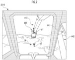
- the operator is allowed to grasp the position of the work mechanism 440 (the attachment 445) constituting the work machine 40 and the position of the second index point pz on the surface of the object Obj through the work environment image and the index image M superimposed thereon that are output to the remote image output device 221 constituting the remote output interface 220 (see FIG. 5 ).
- the second index point p 2 is the result of the first index point pi being projected onto the surface of the object Obj, so this prevents the operator from being provided with position information on unnecessary parts of the work mechanism 440 other than the first index point p 1 , and improves the accuracy with which the operator recognizes the positional relationship between the work mechanism 440 and the object Obj.
- FIGS. 6A to 6C shows a positional relationship between the arm top and the attachment 445 when excavating the ground.
- the work mechanism 440 can apply the strongest force under the arm top, which is the connection point of the attachment 445. Taking this into account, the operator usually brings the tip of the attachment 445 into contact with the ground under the arm top or on the far side from there, then moves the attachment 445 so that the tip comes under the arm top, and performs operation so that the tip finally comes to the nearer side than the arm top. That is, when considering a series of motions for excavation with the attachment 445, the arm top is often more suitable as a position index for the work mechanism 440 than the tip of the attachment 445.
- attachment 445 can be replaced with a breaker, a grapple, a lifting magnet, or the like in addition to the bucket mentioned above, but even if the attachment 445 is replaced, the position of the "arm top" does not change, so there is an advantage that the same image display can be applied.
- the index image M is an image that has directivity toward the second index point pz on the surface of the object Obj, or an image that points to its position by the apex of a substantially triangular shape, an arrow, or the like (see FIG. 5 ). Therefore, it is made possible for the operator to more easily recognize the positional relationship between the work mechanism 440, especially the attachment 445 for which the first index point pi is defined, and the object Obj while avoiding the operator's misunderstanding about the three-dimensional shape of the surface of the object Obj.
- the image display system 10 and the communication function element 121 and the image processing function element 122 constituting the same are implemented by a computer that is present separately from the remote operation device 20 and the work machine 40 in the embodiment described above, an image display system may be mounted on the remote operation device 20 and/or the work machine 40 and the communication function element 121 and/or the image processing function element 122 may be implemented by the remote control device 200 and/or the actual machine control device 400 as another embodiment. In that case, the communication function in the image display system 10 can be omitted.
- the first index point pi is defined as the arm top in the embodiment described above, it may be defined at the tip of the attachment 445. In that case, it is made possible for the operator to more accurately recognize the positional relationship in respect of the contact between the attachment 445 and the object Obj based on the index image M indicating the second index point p 2 resulting from the first index point pi being projected onto the surface of the object Obj.
- the index image M indicating the second index point p 2 resulting from the first index point pi being projected onto the surface of the object Obj in the direction corresponding to the displacement mode of the attachment (e.g., attachment 445) on which the first index point pi is arranged in the work mechanism 440 may be superimposed on the work environment image and output to the remote image output device 221.
- the displacement mode of the work mechanism 440 or the attachment is recognized based on the posture angle sensor and/or the turning angle sensor that constitute the actual machine sensor group 416.
- the displacement mode of the work mechanism 440 or the attachment may be recognized based on the operation mode of the operation levers that constitute the remote operation mechanism 211.
- the index image M indicating the second index point p 2 resulting from the first index point pi being projected vertically downward onto the surface of the object Obj is superimposed on the work environment image and output to the remote image output device 221.
- the index image M indicating the second index point p 2 resulting from the first index point pi being projected onto the surface of the object Obj in a forward and downward direction of the work machine 40 is superimposed on the work environment image and output to the remote image output device 221.
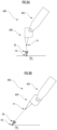
- FIG. 7A when the attachment 445 is displaced vertically downward, the index image M indicating the second index point p 2 resulting from the first index point pi being projected vertically downward onto the surface of the object Obj is superimposed on the work environment image and output to the remote image output device 221.
- the index image M indicating the second index point p 2 resulting from the first index point pi being projected onto the surface of the object Obj in a backward and downward direction of the work machine 40 is superimposed on the work environment image and output to the remote image output device 221.
- the image display system having this configuration, it is possible to improve the accuracy with which the operator recognizes the positional relationship between the first index point pi of the work mechanism 440 and the second index point pz on the surface of the object Obj in the work environment image in the direction corresponding to the displacement mode of the work mechanism 440 constituting the work machine 40 through the work environment image and the index image M superimposed thereon that are output to the remote image output device 221 of the remote operation device 20.
- the index image M indicating the second index point p 2 resulting from the first index point pi being projected onto the surface of the object Obj in the direction corresponding to the posture mode of the work mechanism 440 or the attachment 445 may be superimposed on the work environment image and output to the remote image output device 221.
- the index image M indicating the second index point p 2 resulting from the first index point pi being projected vertically downward onto the surface of the object Obj is superimposed on the work environment image and output to the remote image output device 221.
- the index image M indicating the second index point p 2 resulting from the first index point pi being projected onto the surface of the object Obj in a forward and downward direction of the work machine 40 is superimposed on the work environment image and output to the remote image output device 221.
- the index image M indicating the second index point p 2 resulting from the first index point pi being projected onto the surface of the object Obj in a backward and downward direction of the work machine 40 is superimposed on the work environment image and output to the remote image output device 221.
- the operator can easily recognize the position and direction of action on the object depending on the posture mode of the work mechanism 440 or the attachment 445 constituting the work machine 40 through the work environment image and the index image M superimposed thereon that are output to the remote image output device 221 of the remote operation device 20, so the operator's recognition accuracy can be improved and work efficiency can be improved.
- the first index point is defined on the attachment 445, and while transmission is continued (a specific operation is continued) after the start of transmission of a specific remote operation command, the position information of the first index point may be not updated but remain the position of the first index point pi immediately before the operation command is transmitted.
- a lever of the remote operation mechanism is provided with an operation switch that is a push switch for causing a breaker 445, which is the attachment 445, to work, and when an operation is performed using the remote operation mechanism 211 such that the breaker 445 works, a remote operation command to cause the breaker 445 to work is transmitted to the work machine 40 by the remote operation device 20, and an update stop signal is transmitted to the image display system 10 so as not to update the position information of the first index point pi. Further, the update stop signal is continuously transmitted while the operation switch is pressed. As a result, the position information of the first index point pi remains the position information immediately before the operation switch is operated while the operation is continued. When the operation switch is no longer pressed, the update stop signal to the image display system 10 is no longer transmitted. As a result, updating of the position information of the first index point pi is resumed.
- the position information of the first index point is not updated while the attachment 445 is at work. Therefore, the work environment image and the index image M superimposed thereon that are output to the remote image output device 221 of the remote operation device 20 vibrate because of vibration of the first index point due to vibration of the attachment 445 that is caused by the working of the attachment 445. This can prevent a phenomenon in which the operator who is performing remote operation while gazing at the index image M gets motion sickness.
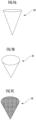
- a three-dimensional index image M in the work environment image may be output to the remote image output device 221 of the remote operation device 20.
- a substantially conical index image M that has a central axis parallel to the vertical direction of the real space and whose apex is directed downward in real space as shown in FIG. 9A is superimposed on the work environment image and output to the remote image output device 221.
- the second index point p 2 is defined as a result of the first index point pi being projected onto the surface of the object Obj in a forward and downward direction of the work machine 40 (see FIGS. 7B and 8B )
- a substantially conical index image M whose apex is directed forward and downward in real space as shown in FIG.
- the index image M output to the remote image output device 221 of the remote operation device 20 is a three-dimensional image, the operator is allowed to easily grasp the positional relationship between the first index point pi of the work mechanism 440 and the second index point pz on the surface of the object Obj through the output form of the index image M.
- An index image M indicating the second index point p 2 resulting from the first index point p 1 , whose position differs depending on the displacement mode of the work mechanism 440, being projected onto the surface of the object Obj may be superimposed on the work environment image and output to the remote image output device 221 of the remote operation device 20.
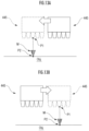
- the center point of the tip of the bucket 445 is defined as the first index point pi as shown in FIG. 10A .
- a counterclockwise turn of the upper turning body 420 with respect to the lower traveling body 410 as viewed from above is estimated, predicted, or measured (see the left-pointing white arrow) according to the operation mode of the remote operation mechanism 211 and/or the actual machine operating mechanism 411 or based on the output signal from the actual machine sensor group 416, a point on the left side of the tip of the bucket 445 is defined as the first index point pi as shown in FIG. 10B .
- a point on the right side of the tip of the bucket 445 is defined as the first index point pi as shown in FIG. 10C .
- the index image M indicating the second index point p 2 resulting from the first index point pi being projected onto the surface of the object Obj is superimposed on the work environment image and output to the remote image output device 221.
- the part of the work mechanism 440 that should be gazed at changes depending on the mode of change of the position and/or posture of the work mechanism 440. For example, if the operation is to turn the upper turning body 420 with respect to the lower traveling body 410, the part is the foremost end in the turning direction, and if the operation is to move the work mechanism 440 away from the center of the machine, the part is the foremost end in the direction in which the work mechanism 440 moves away from the center of the machine.
- the image display system having this configuration, it becomes easier to grasp the positional relationship between the part to be gazed at and the object Obj according to the mode of change of the position and/or posture of the work mechanism 440 constituting the work machine 40 through the work environment image and the index image M superimposed thereon that are output to the remote image output device 221 of the remote operation device 20, and the operator's recognition accuracy can be improved.
- a plurality of index images M indicating a respective plurality of second index points p 2 resulting from a respective plurality of first index points pi being projected onto the surface of the object Obj may be superimposed on the work environment image and output to the remote image output device 221 of the remote operation device 20.
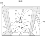
- the left end point and the right end point of the tip of the attachment 445 are defined as first index points p 11 and p 12 , respectively, and a plurality of index images M 1 and M 2 indicating the second index points p 21 and p 22 , respectively, resulting from the first index points p 11 and p 12 , respectively, being projected vertically downward onto the surface of the object Obj may be superimposed on the work environment image and output to the remote image output device 221 of the remote operation device 20.
- the respective numbers of the first index points pi and their corresponding second index points p 2 may be three or more.
- the operator is allowed to grasp the respective positions of the plurality of second index points p 21 and p 22 resulting from the plurality of first index points pn and p 12 , respectively, of the work mechanism 440 being projected onto the surface of the object Obj through the work environment image and the plurality of index images M 1 and M 2 that are output to the remote image output device 221 of the remote operation device 20.
- This improves the accuracy with which the operator recognizes the positional relationship between the work mechanism 440 and the object Obj as compared to the case where only a single index image is output to the remote image output device 221.
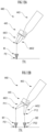
- a plurality of index images M directed toward a respective plurality of second index points p 2 corresponding to a respective plurality of first index points pi whose relative positions change as the posture of the work mechanism 440 changes may be superimposed on the work environment image and output to the remote image output device 221 of the remote operation device 20.
- the centroid of the respective tips of the pair of constituent members 4451 and 4452 is defined as a first index point p 1
- a single index image M indicating the second index point p 2 resulting from the first index point pi being projected onto the surface of the object Obj is superimposed on the work environment image and output to the remote image output device 221 of the remote operation device 20.
- the operator is allowed to grasp the respective positions of the plurality of second index points p 21 and p 22 resulting from the respective plurality of first index points p 11 and p 12 , whose relative positions change as the posture of the work mechanism 440 (e.g., the pair of constituent members 4451 and 4452 of the attachment 445) changes, being projected onto the surface of the object through the work environment image and the plurality of index images that are output to the remote image output device of the remote operation device 20.
- This improves the accuracy with which the operator recognizes the positional relationship between the plurality of parts of the work mechanism 440 and the object Obj that corresponds to the mode of change of the posture.
- the plurality of parts may be composed of, for example, one part of the attachment 445 and another part of the arm 443 and/or the boom 441.
- the center point of the tip of the attachment 445 and the center point of the tip (the connection part with the attachment 445) of the arm 443 may be defined as the first index points p 11 and p 12 , respectively.
- the index images M 1 and M 2 superimposed on the work environment image are identifiably expressed using colors, shapes, patterns, or a combination thereof, so that the operator can recognize the mode of arrangement of the index images M 1 and M 2 in the front-rear direction in real space and therefore the posture of the attachment 445 (e.g., a bucket).
- an index image M having directivity toward the second index point p 2 is output to the remote image output device 221 in the embodiment described above (see FIG. 5 )
- an index image M having no directivity toward the second index point p 2 may be output to the remote image output device 221 as another embodiment.
- an index image M such as a two-dimensional figure in a specified shape such as a circle or a square with the second index point pz as the center or centroid arranged in a posture parallel to the horizontal plane may be output to the remote image output device 221.
- An index image M such as a three-dimensional figure in a specified shape such as a sphere, a cube, or a polyhedron with the second index point pz as the center or centroid arranged in a posture parallel to the horizontal plane may be output to the remote image output device 221.
- the index image M indicating the second index point p 2 resulting from the first index point pi being projected onto the surface of the object Obj is superimposed on the work environment image and output to the remote image output device 221.
- the operator can recognize the mode of change of the position and/or posture in which a part or the whole of the communication delay time and the response delay time of the work mechanism 440 constituting the work machine 40 is taken into account through the work environment image and the index image M superimposed thereon that are output to the remote image output device 221 of the remote operation device 20, so the accuracy of recognizing the positional relationship of the work mechanism 440 with respect to the object Obj is improved in consideration of the operating environment specific to remote operation, and operations can be performed more efficiently.
- the index image having directivity toward the second index point is superimposed on the work environment image and output to the output interface of the remote operation device.
- the index image output to the output interface of the remote operation device has directivity toward the second index point (the index image points to the position of the second index point), so the operator is allowed to easily grasp the positional relationship between the first index point of the work mechanism and the second index point on the surface of the object.
- the index image indicating the second index point resulting from the first index point being projected onto the surface of the object in a direction corresponding to a displacement mode of the work mechanism or a posture mode of the work mechanism is superimposed on the work environment image and output to the output interface of the remote operation device.
- the image display system having this configuration, it is possible to improve the accuracy with which the operator recognizes the positional relationship between the first index point of the work mechanism and the second index point on the surface of the object in the work environment image in the direction corresponding to the displacement mode or the posture mode of the work mechanism constituting the work machine through the work environment image and the index image superimposed thereon that are output to the output interface of the remote operation device.
- the index image indicating the second index point resulting from the first index point, whose position differs depending on a displacement mode of the work mechanism, being projected onto the surface of the object is superimposed on the work environment image and output to the output interface of the remote operation device.
- the image display system of the present invention it is possible to improve the accuracy with which the operator recognizes the positional relationship between the first index point of the work mechanism, which is displaced to a position corresponding to the displacement mode of the work mechanism constituting the work machine, and the second index point on the surface of the object in the work environment image through the work environment image and the index image superimposed thereon that are output to the output interface of the remote operation device.
- a position of the first index point of the work mechanism that is determined based on an output from a sensor mounted on the work machine is recognized, and then the index image indicating the second index point resulting from the first index point being projected onto the surface of the object is superimposed on the work environment image and output to the output interface of the remote operation device.
- the operator is allowed to easily grasp or infer the positional relationship between the first index point and the second index point resulting from the first index point being projected onto the surface of the object through the index image output to the output interface of the remote operation device.
- the first index point is set at an arm top.
- the position of the tip of the attachment is operated relative to the position of the arm top in a series of motions for excavation in order to apply strong force, so the arm top is suitable as the position index. Furthermore, since the position of the arm top does not change even if the attachment is replaced, there is an advantage that the same image display can be applied.
- a plurality of the index images indicating a respective plurality of the second index points resulting from a respective plurality of the first index points being projected onto the surface of the object are superimposed on the work environment image and output to the output interface of the remote operation device.
- the operator is allowed to grasp the respective positions of the plurality of second index points resulting from the respective plurality of first index points of the work mechanism being projected onto the surface of the object through the work environment image and the plurality of index images that are output to the output interface of the remote operation device. This improves the accuracy with which the operator recognizes the positional relationship between the work mechanism and the object as compared to the case where only a single index image is output to the output interface of the remote operation device.
- a plurality of the index images directed toward a respective plurality of the second index points corresponding to a respective plurality of the first index points whose relative positions change as the posture of the work mechanism changes are superimposed on the work environment image and output to the output interface of the remote operation device.
- the operator is allowed to grasp the respective positions of the plurality of second index points resulting from the respective plurality of first index points, whose relative positions change as the posture of the work mechanism changes, being projected onto the surface of the object through the work environment image and the plurality of index images that are output to the output interface of the remote operation device. This improves the accuracy with which the operator recognizes the positional relationship between the plurality of parts of the work mechanism and the object that corresponds to the mode of change of the posture.
Landscapes
- Engineering & Computer Science (AREA)
- Mining & Mineral Resources (AREA)
- Civil Engineering (AREA)
- General Engineering & Computer Science (AREA)
- Structural Engineering (AREA)
- Manipulator (AREA)
- Component Parts Of Construction Machinery (AREA)
- Processing Or Creating Images (AREA)
Abstract
Description
- The present invention relates to a technique for assisting an operator's remote operation of a work machine such as a hydraulic excavator.
- There has been proposed a technique in which information on the position of a work tool obtained using the posture of a work apparatus and information on the position of the ground, which is a work object, obtained from information on the distance to the work object of a work machine determined by a distance detection device are used to generate an image of a portion corresponding to the work tool along the surface of the work object opposing the work tool, the generated image is combined with an image of the work object captured by an image capturing device, and the combined image is displayed on a display device (see, e.g., Patent Literature 1). This suppresses reduction in work efficiency in working using a work machine comprising a work apparatus having a work tool.
- Patent Literature 1:
Japanese Patent No. 6777375 - However, when the work apparatus is aligned with the work object, the position of the work apparatus is represented by an image formed along the topography according to the conventional technique. Therefore, since unnecessary position information other than a predetermined part of the work apparatus is also displayed at the same time, it can be difficult to grasp the position of the work apparatus with respect to the work object, which can make it difficult to work efficiently.
- Therefore, an object of the present invention is to provide a system and the like that can improve the accuracy with which an operator recognizes the positional relationship between a work mechanism constituting a work machine and an object present around the work machine.
- An image display system according to the present invention is
an image display system, wherein on a work environment image representing a situation of a work mechanism constituting a work machine and an object present around the work machine, an index image indicating a second index point resulting from a first index point of the work mechanism being projected onto a surface of the object is superimposed and output to an output interface of a remote operation device for remotely operating the work machine. - According to the image display system having this configuration, an operator is allowed to grasp the position of the work mechanism constituting the work machine and the position of the second index point on the surface of the object through the work environment image and the index image superimposed thereon that are output to the output interface of the remote operation device. The second index point is the result of the first index point being projected onto the surface of the object, and is not along the surface shape of the object. This prevents the operator from being provided with position information on unnecessary parts of the work mechanism other than the first index point, and improves the accuracy with which the operator recognizes the positional relationship between the work mechanism and the object.
-
-
FIG. 1 is an explanatory diagram regarding a configuration of an image display composite system and an image display system. -
FIG. 2 is an explanatory diagram regarding a configuration of a remote operation device. -
FIG. 3 is an explanatory diagram regarding a configuration of a work machine. -
FIG. 4 is an explanatory diagram regarding functions of the image display system. -
FIG. 5 is an explanatory diagram regarding a work environment image and one display form of an index image. -
FIG. 6A is an explanatory diagram regarding a relationship between an arm top position and a display mode of the index image. -
FIG. 6B is an explanatory diagram regarding a relationship between the arm top position and the display mode of the index image. -
FIG. 6C is an explanatory diagram regarding a relationship between the arm top position and the display mode of the index image. -
FIG. 7A is an explanatory diagram regarding a relationship between a displacement mode of a work mechanism and directivity of the index image. -
FIG. 7B is an explanatory diagram regarding a relationship between a displacement mode of the work mechanism and directivity of the index image. -
FIG. 7C is an explanatory diagram regarding a relationship between a displacement mode of the work mechanism and directivity of the index image. -
FIG. 8A is an explanatory diagram regarding a relationship between a posture mode of the work mechanism and directivity of the index image. -
FIG. 8B is an explanatory diagram regarding a relationship between a posture mode of the work mechanism and directivity of the index image. -
FIG. 8C is an explanatory diagram regarding a relationship between a posture mode of the work mechanism and directivity of the index image. -
FIG. 9A is an explanatory diagram regarding a display form of a three-dimensional index image. -
FIG. 9B is an explanatory diagram regarding a display form of the three-dimensional index image. -
FIG. 9C is an explanatory diagram regarding a display form of the three-dimensional index image. -
FIG. 10A is an explanatory diagram regarding a relationship between a displacement mode of the work mechanism and the position of a first index point. -
FIG. 10B is an explanatory diagram regarding a relationship between a displacement mode of the work mechanism and the position of the first index point. -
FIG. 10C is an explanatory diagram regarding a relationship between the displacement mode of the work mechanism and the position of the first index point. -
FIG. 11 is an explanatory diagram regarding the work environment image and another display form of index images. -
FIG. 12A is an explanatory diagram regarding a relationship between a motion mode of the work mechanism and a display form of an index image. -
FIG. 12B is an explanatory diagram regarding a relationship between a motion mode of the work mechanism and a display form of index images. -
FIG. 13A is an explanatory diagram regarding a relationship between a displacement mode of the work mechanism and the position of the first index point. -
FIG. 13B is an explanatory diagram regarding a relationship between a displacement mode of the work mechanism and the position of the first index point. - An image display composite system shown in
FIG. 1 is composed of animage display system 10, aremote operation device 20, and/or awork machine 40 to be remotely operated by theremote operation device 20. Theimage display system 10, theremote operation device 20, and thework machine 40 are configured to be able to communicate with each other over a network. An intercommunication network between theimage display system 10 and theremote operation device 20 may be identical to or different from an intercommunication network between theimage display system 10 and thework machine 40. - In this embodiment, the
image display system 10 is implemented by a computer that is present separately from theremote operation device 20 and thework machine 40, and comprises adatabase 102, acommunication function element 121, and an imageprocessing function element 122. Thedatabase 102 stores and holds captured image data and the like. Thedatabase 102 may be implemented by a database server that can communicate with theimage display system 10. The function elements are implemented by an arithmetic processing device (e.g., a single-core processor and/or a multi-core processor or a processor core constituting the same), read necessary data and software from a storage device such as a memory, and execute later-described arithmetic processing according to the software on the data. - The
remote operation device 20 comprises aremote control device 200, aremote input interface 210, aremote output interface 220, and remotewireless communication equipment 224. Theremote control device 200 is implemented by an arithmetic processing device (e.g., a single-core processor and/or a multi-core processor or a processor core constituting the same), reads necessary data and software from a storage device such as a memory, and executes arithmetic processing according to the software on the data. - The
remote input interface 210 comprises aremote operation mechanism 211. Theremote output interface 220 comprises a remoteimage output device 221. - The
remote operation mechanism 211 includes a travel operation device, a turning operation device, a boom operation device, an arm operation device, and a bucket operation device. Each of the operation devices has an operation lever which receives a pivot operation. The operation lever of the travel operation device (travel lever) is operated to move alower traveling body 410 of thework machine 40. The travel lever may also function as a travel pedal. For example, a travel pedal which is fixed to a base portion or a lower end portion of the travel lever may be provided. The operation lever of the turning operation device (turn lever) is operated to move a hydraulic turning motor constituting aturning mechanism 430 of thework machine 40. The operation lever of the boom operation device (boom lever) is operated to move aboom cylinder 442 of thework machine 40. The operation lever of the arm operation device (arm lever) is operated to move anarm cylinder 444 of thework machine 40. The operation lever of the bucket operation device (bucket lever) is operated to move abucket cylinder 446 of thework machine 40. - As shown in
FIG. 2 , for example, the operation levers constituting theremote operation mechanism 211 are disposed around a seat St for an operator to sit on. The seat St is in the form of a high back chair with armrests, but may be a seat in any form on which the operator can sit, for example, a form such as a low back chair with no headrest, or a form such as a chair with no backrest. - A pair of left and
right travel levers 2110 corresponding to left and right crawlers are disposed side by side on the left side and right side in front of the seat St. One operation lever may also function as a plurality of operation levers. For example, a left-side operation lever 2111 provided in front of a left-side frame of the seat St shown inFIG. 2 may function as an arm lever when the left-side operation lever 2111 is operated in a front-rear direction, and also function as a turn lever when the left-side operation lever 2111 is operated in a left-right direction. Similarly, a right-side operation lever 2112 provided in front of a right-side frame of the seat St shown inFIG. 2 may function as a boom lever when the right-side operation lever 2112 is operated in the front-rear direction, and also function as a bucket lever when the right-side operation lever 2112 is operated in the left-right direction. A lever pattern may be changed in any manner according to an operation instruction from the operator. - For example, as shown in
FIG. 2 , the remoteimage output device 221 is composed of a central remoteimage output device 2210, a left-side remoteimage output device 2211, and a right-side remoteimage output device 2212 disposed in front, on the diagonally front left side, and the diagonally front right side, respectively, of the seat St, each remote image output device having a substantially rectangular screen. The respective screens (image display areas) of the central remoteimage output device 2210, the left-side remoteimage output device 2211, and the right-side remoteimage output device 2212 may have the same shape and size, or different shapes and sizes. - As shown in
FIG. 2 , the right edge of the left-side remoteimage output device 2211 is adj acent to the left edge of the central remoteimage output device 2210 such that the screen of the central remoteimage output device 2210 and the screen of the left-side remoteimage output device 2211 form an inclination angle θ1 (e.g., 120° ≤ θ1 ≤ 150°). As shown inFIG. 2 , the left edge of the right-side remoteimage output device 2212 is adj acent to the right edge of the central remoteimage output device 2210 such that the screen of the central remoteimage output device 2210 and the screen of the right-side remoteimage output device 2212 form an inclination angle θ2 (e.g., 120° ≤ θ2 ≤ 150°). The inclination angles θ1 and θ2 may be the same, or different from each other. - The respective screens of the central remote
image output device 2210, the left-side remoteimage output device 2211, and the right-side remoteimage output device 2212 may be parallel to a vertical direction, or inclined with respect to the vertical direction. At least one image output device of the central remoteimage output device 2210, the left-side remoteimage output device 2211, and the right-side remoteimage output device 2212 may be composed of a plurality of split image output devices. For example, the central remoteimage output device 2210 may be composed of a pair of image output devices which have substantially rectangular screens and are disposed adjacent to each other in the up-down direction. - The remote
image output device 221 may be composed of a single image output device that is curved or bent so as to surround the seat St. The single image output device may be implemented by, for example, the central remoteimage output device 2210. The remoteimage output device 221 may be composed of two image output devices (e.g., the central remoteimage output device 2210 and the left-side remoteimage output device 2211 or the right-side remote image output device 2212). - The
work machine 40 comprises an actualmachine control device 400, an actualmachine input interface 41, an actualmachine output interface 42, actual machinewireless communication equipment 422, and awork mechanism 440. The actualmachine control device 400 is implemented by an arithmetic processing device (a single-core processor or a multi-core processor or a processor core constituting the same), reads necessary data and software from a storage device such as a memory, and executes arithmetic processing according to the software on the data. - The
work machine 40 is, for example, a crawler excavator (a construction machine), and as shown inFIG. 3 , comprises a crawler-typelower traveling body 410, and anupper turning body 420 mounted on thelower traveling body 410 via aturning mechanism 430 in a turnable manner. A cab 424 (driver's cabin) is provided on the front left side of theupper turning body 420. Thework mechanism 440 is provided at the front center of theupper turning body 420. - The actual
machine input interface 41 comprises an actualmachine operating mechanism 411, an actual machineimage capturing device 412, an actual machinedistance measuring device 414, and an actualmachine sensor group 416. The actualmachine operating mechanism 411 comprises a plurality of operation levers disposed in the same manner as theremote operation mechanism 211 around the seat installed in thecab 424. Thecab 424 is provided with a driving mechanism or a robot that receives a signal corresponding to an operation mode of the remote operation levers, and moves the actual machine operation levers based on the received signal. The actual machineimage capturing device 412 is installed, for example, in thecab 424, and captures an image of the environment including at least a portion (e.g., an attachment 445) of thework mechanism 440 through a front window. Some or all of the front window and the side windows may be omitted. The actual machinedistance measuring device 414 is a device for measuring the real space distance to an object present around thework machine 40 and therefore its real space position, and is implemented by, for example, LiDAR and a TOF sensor. The actualmachine sensor group 416 is composed of various sensors for measuring the motion state of thework machine 40, such as a turning angle sensor for measuring the turning angle of theupper turning body 420 with respect to thelower traveling body 410, and a posture angle sensor for measuring the posture angle representing the posture of thework mechanism 440. - The actual
machine output interface 42 comprises the actual machinewireless communication equipment 422. - As shown in
FIG. 3 , thework mechanism 440 as a work mechanism comprises aboom 441 attached to theupper turning body 420 in an elevatable manner, anarm 443 pivotably connected to a tip of theboom 441, and an attachment 445 (e.g., a bucket) pivotably connected to a tip of thearm 443. Thework mechanism 440 are equipped with theboom cylinder 442, thearm cylinder 444, and thebucket cylinder 446, each implemented by an extendable hydraulic cylinder. - The
boom cylinder 442 is interposed between theboom 441 and theupper turning body 420 such that theboom cylinder 442 is supplied with hydraulic oil to extend and shorten, thereby pivoting theboom 441 in an elevating direction. Thearm cylinder 444 is interposed between thearm 443 and theboom 441 such that thearm cylinder 444 is supplied with hydraulic oil to extend and shorten, thereby pivoting thearm 443 around a horizontal axis with respect to theboom 441. Thebucket cylinder 446 is interposed between theattachment 445 and thearm 443 such that thebucket cylinder 446 is supplied with hydraulic oil to extend and shorten, thereby pivoting theattachment 445 around a horizontal axis with respect to thearm 443. -
FIG. 4 is a flowchart illustrating the image display system having the above-described configuration and functions of the image display system. In the flowchart, the blocks "C•" are used to simplify the description, mean the transmission and/or reception of data, and mean a conditional branch in which the processing in the branch direction is executed under the condition of having transmitted and/or received the data. The flowchart is repeated for each control period, and after the process has reached "END", it returns to "START" and executes the subsequent processing. - In the
remote operation device 20, it is determined whether there is an environment confirmation request operation (a second specified operation) performed by the operator through the remote input interface 210 (FIG. 4 /STEP 210). For example, the "environment confirmation request" is an operation, such as a tap on theremote input interface 210, for the operator to instruct thework machine 40, which the operator intends to remotely operate, to perform an environment confirmation request operation. If the determination result is negative (FIG. 4 /STEP 210 .. NO), the process returns to START. On the other hand, if the determination result is affirmative (FIG. 4 /STEP 210 .. YES), an environment confirmation request is transmitted to theimage display system 10 through the remote wireless communication equipment 224 (FIG. 4 /STEP 211). - In the
image display system 10, when the environment confirmation request is received, the environment confirmation request is transmitted to thecorresponding work machine 40 by the communication function element 121 (FIG. 4 /C10). The environment confirmation request may be transmitted to thework machine 40 not via theimage display system 10. - In the
work machine 40, when the environment confirmation request is received through the actual machine wireless communication equipment 422 (FIG. 4 /C40), a captured image of a work object Obj (e.g., the ground, earth and sand, materials, and/or structures that are present around the work machine 40) is acquired by the actual machineimage capturing device 412, a three-dimensional image of the work object Obj is also acquired by the actual machinedistance measuring device 414, and three-dimensional image data representing the three-dimensional image is transmitted to theimage display system 10 through the actual machine wireless communication equipment 422 (FIG. 4 /STEP 410). - The three-dimensional image is an image having the direction of and the distance to the work object Obj or the real space position of the work object Obj acquired through the actual machine
distance measuring device 414. The "real space position" is defined by coordinate values in a real space coordinate system (e.g., latitude, longitude, and altitude) or coordinate values in an actual machine coordinate system (a coordinate system whose position or posture is fixed relative to the work machine 40). When the work object Obj appears in the captured image, the real space position of each point constituting the point cloud of the surface of the work object Obj corresponding to each pixel of the three-dimensional image is included as the pixel value of that pixel. - The three-dimensional image data may be acquired and transmitted as a combination of data of the captured image acquired through the actual machine
image capturing device 412 or a model image equivalent thereto and data of the distance or real space position acquired through the actual machinedistance measuring device 414, which are separate data. - The captured image in which at least the work object Obj appears may not be acquired through the actual machine
image capturing device 412, but through an image capturing device installed around thework machine 40, an image capturing device mounted on an unmanned drone, and/or an image capturing device of equipment carried by a site worker. The distance or real space position, which is the pixel value of the three-dimensional image, may be acquired through a distance measuring device installed around thework machine 40 and/or a distance measuring device mounted on an unmanned drone. - Instead of the combination of the actual machine
image capturing device 412 and the actual machinedistance measuring device 414, a captured image and a three-dimensional image of the work object Obj may be acquired through a stereo camera (a pair of left and right actual machine image capturing devices 412) mounted on thework machine 40. - In the
image display system 10, when the three-dimensional image data is received by the communication function element 121 (FIG. 4 /C11), work environment image data corresponding to the three-dimensional image data is transmitted to theremote operation device 20 by the image processing function element 122 (FIG. 4 /STEP 110). The work environment image data is image data representing a simulated work environment image generated based on the captured image data, in addition to the captured image data itself (which does not include real space positions and distance information as pixel values), which is the basis of the three-dimensional image data. - In the
remote operation device 20, when the work environment image data is received through the remote wireless communication equipment 224 (FIG. 4 /C21), a work environment image corresponding to the work environment image data is output to the remoteimage output device 221 by the remote control device 200 (FIG. 4 /STEP 212). - As a result, for example, as shown in
FIG. 5 , a work environment image in which theboom 441, thearm 443, and theattachment 445, which are part of thework mechanism 440, as well as earth and sand, which are the object Obj, etc. are captured in front of thecab 424 through the window frame defining thecab 424 is output to the remoteimage output device 221. - In the
work machine 40, the real space position of a first index point pi of thework mechanism 440 is acquired by the actualmachine sensor group 416, and data representing the real space position of the first index point pi is transmitted to theimage display system 10 through the actual machine wireless communication equipment 422 (FIG. 4 /STEP 412). - The process of transmitting the three-dimensional image data (see
FIG. 4 /STEP 410) and the process of transmitting the data representing the real space position of the first index point pi (seeFIG. 4 /STEP 412) may be executed simultaneously as a process of transmitting a batch of data. - Specifically, a point corresponding to the tip (arm top) of the
arm 443 is defined as the first index point pi. The real space position of the first index point pi defined in thework mechanism 440 is forward-kinematically calculated based on an output signal from the posture angle sensor that constitutes the actualmachine sensor group 416 mounted on thework machine 40 and the size of each component of thework mechanism 440. The posture angle sensor is configured to output a signal corresponding to at least part of the elevation angle of theboom 441 with respect to theupper turning body 420, the pivot angle of thearm 443 at the connection part with theboom 441, and the pivot angle of theattachment 445 at the connection part with thearm 443. Any point on theboom 441, thearm 443, theattachment 445, and the like that constitute thework mechanism 440 may be defined as the first index point pi. - When the first index point pi of the
work mechanism 440 appears in the three-dimensional image, the real space position of the first index point pi may be recognized by the actualmachine control device 400 based on the three-dimensional image. Specifically, using image analysis processing (e.g., grayscaling processing, edge extraction processing, and/or pattern matching processing) of the three-dimensional image, the average value of the pixel values of one or more pixels corresponding to the first index point pi in thework mechanism 440 is recognized as the real space position of the first index point pi. Based on one of the real space position of each point of thework mechanism 440 recognized using the posture angle sensor and the real space position that is the pixel value of the three-dimensional image, the other may be corrected. - In the
image display system 10, when the data representing the real space position of the first index point pi is received (FIG. 4 /C12), the real space position of a second index point p2 is recognized by the imageprocessing function element 122 based on the real space position of the first index point pi and the real space positions or three-dimensional shape of points constituting the point cloud of the surface of the object Obj included in the three-dimensional image (FIG. 4 /STEP 112). The second index point p2 is a point resulting from the first index point pi being projected onto the surface of the obj ect Obj. The projection direction of the first index point pi onto the surface of the object Obj is, for example, the vertical direction. In this case, among the points on the surface of the object Obj, the real space position of the point with the same horizontal position (x (longitude), y (latitude)) as the first index point pi or the point closest thereto, or the centroid of a plurality of points at horizontal positions close to the first index point pi is recognized as the second index point pz. - When the
work machine 40 or theupper turning body 420 is tilted with respect to the vertical axis of the real space, the projection direction of the first index point pi onto the surface of the object Obj may be defined as the direction tilted in the same way with respect to the vertical axis of the real space. The tilt angle of thework machine 40 with respect to the vertical axis is measured by a machine body tilt angle sensor (e.g., a gyro sensor) that constitutes the actualmachine sensor group 416. - When the first index point pi of the
work mechanism 440 appears in the three-dimensional image, the recognition of the real space position of the first index point pi and the transmission of data by the actual machine control device 400 (FIG. 4 /STEP 412) may be omitted. In this case, the imageprocessing function element 122 uses image analysis processing (e.g., grayscaling processing, edge extraction processing, and/or pattern matching processing) of the three-dimensional image to recognize one or more pixels corresponding to the point defined as the first index point pi in thework mechanism 440, and recognize the pixel values of the pixels or their average value as the real space position of the first index point pi. - Further, in the
image display system 10, index image data obtained by superimposing an index image M indicating the second index point pz on the work environment image using the imageprocessing function element 122 is transmitted to the remote operation device 20 (FIG. 4 /STEP 114). The command includes the real space position of the second index point p2 and/or the pixel position (u, v) corresponding to the second index point p2 in the three-dimensional image or the work environment image. - In the
remote operation device 20, when the index image data is received through the remote wireless communication equipment 224 (FIG. 4 /C22), the index image M corresponding to the command is output by theremote control device 200 to the remoteimage output device 221 in the form of being superimposed on the work environment image (FIG. 4 /STEP 214). - The process of transmitting the work environment image data (see
FIG. 4 /STEP 110) and the process of transmitting the index image data (seeFIG. 4 /STEP 114) from theimage display system 10 to theremote operation device 20 may be executed simultaneously as a process of transmitting a batch of data. In this case, in theremote operation device 20, the process of outputting the work environment image (seeFIG. 4 /STEP 212) and the process of outputting the index image superimposed on the work environment image (seeFIG. 4 /STEP 214) may be executed simultaneously as a single image output process. - As a result, for example, as shown in
FIG. 5 , the index image M indicating the second index point p2 resulting from the first index point pi being projected onto the surface of the object Obj (e.g., earth and sand around the work machine 40) is output to the remoteimage output device 221 in the form of being superimposed on the work environment image. Here, the index image M is an image of a triangular or arrow-shaped figure directed toward the second index point p2 in the vertical direction in real space. As shown inFIG. 5 , the first index point pi and the second index point p2 may be displayed superimposed on the captured image, or the superimposed display of the first index point pi and/or the second index point p2 may be omitted. - In the
remote operation device 20, an operation mode of theremote operation mechanism 211 is recognized by theremote control device 200, and a remote operation command corresponding to the operation mode is transmitted to theimage display system 10 through the remote wireless communication equipment 224 (FIG. 4 /STEP 220). - In the
image display system 10, when the remote operation command is received by the imageprocessing function element 122, the remote operation command is transmitted to thework machine 40 by the communication function element 121 (FIG. 4 /C14). The remote operation command may be transmitted to thework machine 40 not via theimage display system 10. - In the
work machine 40, when the operation command is received by the actualmachine control device 400 through the actual machine wireless communication equipment 422 (FIG. 4 /C44), the motion of thework mechanism 440 and the like is controlled (FIG. 4 /STEP 420). For example, a work of scooping up earth and sand, which is the object Obj, in front of thework machine 40 with theattachment 445, turning theupper turning body 420, and then dropping the earth and sand from theattachment 445 is executed. - According to the image display system constituting the image display system having this configuration, the operator is allowed to grasp the position of the work mechanism 440 (the attachment 445) constituting the
work machine 40 and the position of the second index point pz on the surface of the object Obj through the work environment image and the index image M superimposed thereon that are output to the remoteimage output device 221 constituting the remote output interface 220 (seeFIG. 5 ). The second index point p2 is the result of the first index point pi being projected onto the surface of the object Obj, so this prevents the operator from being provided with position information on unnecessary parts of thework mechanism 440 other than the first index point p1, and improves the accuracy with which the operator recognizes the positional relationship between thework mechanism 440 and the object Obj. - Each of
FIGS. 6A to 6C shows a positional relationship between the arm top and theattachment 445 when excavating the ground. Thework mechanism 440 can apply the strongest force under the arm top, which is the connection point of theattachment 445. Taking this into account, the operator usually brings the tip of theattachment 445 into contact with the ground under the arm top or on the far side from there, then moves theattachment 445 so that the tip comes under the arm top, and performs operation so that the tip finally comes to the nearer side than the arm top. That is, when considering a series of motions for excavation with theattachment 445, the arm top is often more suitable as a position index for thework mechanism 440 than the tip of theattachment 445. - Furthermore, the
attachment 445 can be replaced with a breaker, a grapple, a lifting magnet, or the like in addition to the bucket mentioned above, but even if theattachment 445 is replaced, the position of the "arm top" does not change, so there is an advantage that the same image display can be applied. - Further, the index image M is an image that has directivity toward the second index point pz on the surface of the object Obj, or an image that points to its position by the apex of a substantially triangular shape, an arrow, or the like (see
FIG. 5 ). Therefore, it is made possible for the operator to more easily recognize the positional relationship between thework mechanism 440, especially theattachment 445 for which the first index point pi is defined, and the object Obj while avoiding the operator's misunderstanding about the three-dimensional shape of the surface of the object Obj. - Although the
image display system 10 and thecommunication function element 121 and the imageprocessing function element 122 constituting the same are implemented by a computer that is present separately from theremote operation device 20 and thework machine 40 in the embodiment described above, an image display system may be mounted on theremote operation device 20 and/or thework machine 40 and thecommunication function element 121 and/or the imageprocessing function element 122 may be implemented by theremote control device 200 and/or the actualmachine control device 400 as another embodiment. In that case, the communication function in theimage display system 10 can be omitted. - Although the first index point pi is defined as the arm top in the embodiment described above, it may be defined at the tip of the
attachment 445. In that case, it is made possible for the operator to more accurately recognize the positional relationship in respect of the contact between theattachment 445 and the object Obj based on the index image M indicating the second index point p2 resulting from the first index point pi being projected onto the surface of the object Obj. - In response to the index image output command, the index image M indicating the second index point p2 resulting from the first index point pi being projected onto the surface of the object Obj in the direction corresponding to the displacement mode of the attachment (e.g., attachment 445) on which the first index point pi is arranged in the
work mechanism 440 may be superimposed on the work environment image and output to the remoteimage output device 221. The displacement mode of thework mechanism 440 or the attachment is recognized based on the posture angle sensor and/or the turning angle sensor that constitute the actualmachine sensor group 416. The displacement mode of thework mechanism 440 or the attachment may be recognized based on the operation mode of the operation levers that constitute theremote operation mechanism 211. - For example, as shown in
FIG. 7A , when theattachment 445 is displaced vertically downward, the index image M indicating the second index point p2 resulting from the first index point pi being projected vertically downward onto the surface of the object Obj is superimposed on the work environment image and output to the remoteimage output device 221. As shown inFIG. 7B , when theattachment 445 is displaced forward and downward as viewed from thework machine 40, the index image M indicating the second index point p2 resulting from the first index point pi being projected onto the surface of the object Obj in a forward and downward direction of thework machine 40 is superimposed on the work environment image and output to the remoteimage output device 221. As shown inFIG. 7C , when theattachment 445 is displaced backward and downward as viewed from thework machine 40, the index image M indicating the second index point p2 resulting from the first index point pi being projected onto the surface of the object Obj in a backward and downward direction of thework machine 40 is superimposed on the work environment image and output to the remoteimage output device 221. - According to the image display system having this configuration, it is possible to improve the accuracy with which the operator recognizes the positional relationship between the first index point pi of the
work mechanism 440 and the second index point pz on the surface of the object Obj in the work environment image in the direction corresponding to the displacement mode of thework mechanism 440 constituting thework machine 40 through the work environment image and the index image M superimposed thereon that are output to the remoteimage output device 221 of theremote operation device 20. - In response to the index image output command, the index image M indicating the second index point p2 resulting from the first index point pi being projected onto the surface of the object Obj in the direction corresponding to the posture mode of the
work mechanism 440 or theattachment 445 may be superimposed on the work environment image and output to the remoteimage output device 221. - For example, as shown in
FIG. 8A , when a chisel, which is a striking part for striking the object, of abreaker 445, which is theattachment 445 having directional action on the object, is directed vertically downward, the index image M indicating the second index point p2 resulting from the first index point pi being projected vertically downward onto the surface of the object Obj is superimposed on the work environment image and output to the remoteimage output device 221. As shown inFIG. 8B , when the chisel of thebreaker 445 is directed forward and downward as viewed from thework machine 40, the index image M indicating the second index point p2 resulting from the first index point pi being projected onto the surface of the object Obj in a forward and downward direction of thework machine 40 is superimposed on the work environment image and output to the remoteimage output device 221. As shown inFIG. 8C , when the chisel of thebreaker 445 is directed backward and downward as viewed from thework machine 40, the index image M indicating the second index point p2 resulting from the first index point pi being projected onto the surface of the object Obj in a backward and downward direction of thework machine 40 is superimposed on the work environment image and output to the remoteimage output device 221. - According to the image display system having this configuration, the operator can easily recognize the position and direction of action on the object depending on the posture mode of the
work mechanism 440 or theattachment 445 constituting thework machine 40 through the work environment image and the index image M superimposed thereon that are output to the remoteimage output device 221 of theremote operation device 20, so the operator's recognition accuracy can be improved and work efficiency can be improved. - The first index point is defined on the
attachment 445, and while transmission is continued (a specific operation is continued) after the start of transmission of a specific remote operation command, the position information of the first index point may be not updated but remain the position of the first index point pi immediately before the operation command is transmitted. - For example, a lever of the remote operation mechanism is provided with an operation switch that is a push switch for causing a
breaker 445, which is theattachment 445, to work, and when an operation is performed using theremote operation mechanism 211 such that thebreaker 445 works, a remote operation command to cause thebreaker 445 to work is transmitted to thework machine 40 by theremote operation device 20, and an update stop signal is transmitted to theimage display system 10 so as not to update the position information of the first index point pi. Further, the update stop signal is continuously transmitted while the operation switch is pressed. As a result, the position information of the first index point pi remains the position information immediately before the operation switch is operated while the operation is continued. When the operation switch is no longer pressed, the update stop signal to theimage display system 10 is no longer transmitted. As a result, updating of the position information of the first index point pi is resumed. - According to the image display system having this configuration, the position information of the first index point is not updated while the
attachment 445 is at work. Therefore, the work environment image and the index image M superimposed thereon that are output to the remoteimage output device 221 of theremote operation device 20 vibrate because of vibration of the first index point due to vibration of theattachment 445 that is caused by the working of theattachment 445. This can prevent a phenomenon in which the operator who is performing remote operation while gazing at the index image M gets motion sickness. - As described above, when the second index point p2 is defined as a result of the first index point pi being projected onto the surface of the object Obj in a direction corresponding to the displacement mode or the posture mode of the
work mechanism 440 or the attachment, a three-dimensional index image M in the work environment image may be output to the remoteimage output device 221 of theremote operation device 20. - For example, when the second index point p2 is defined as a result of the first index point pi being projected vertically downward onto the surface of the object Obj (see
FIGS. 7A and8A ), a substantially conical index image M that has a central axis parallel to the vertical direction of the real space and whose apex is directed downward in real space as shown inFIG. 9A is superimposed on the work environment image and output to the remoteimage output device 221. When the second index point p2 is defined as a result of the first index point pi being projected onto the surface of the object Obj in a forward and downward direction of the work machine 40 (seeFIGS. 7B and8B ), a substantially conical index image M whose apex is directed forward and downward in real space as shown inFIG. 9B is superimposed on the work environment image and output to the remoteimage output device 221. When the second index point p2 is defined as a result of the first index point pi being projected onto the surface of the object Obj in a backward and downward direction of the work machine 40 (seeFIGS. 7C and8C ), a substantially conical index image M whose apex is directed backward and downward in real space as shown inFIG. 9C is superimposed on the work environment image and output to the remoteimage output device 221. - According to the image display system having this configuration, since the index image M output to the remote
image output device 221 of theremote operation device 20 is a three-dimensional image, the operator is allowed to easily grasp the positional relationship between the first index point pi of thework mechanism 440 and the second index point pz on the surface of the object Obj through the output form of the index image M. - An index image M indicating the second index point p2 resulting from the first index point p1, whose position differs depending on the displacement mode of the
work mechanism 440, being projected onto the surface of the object Obj may be superimposed on the work environment image and output to the remoteimage output device 221 of theremote operation device 20. - For example, when the
upper turning body 420 is not turning with respect to thelower traveling body 410, the center point of the tip of thebucket 445 is defined as the first index point pi as shown inFIG. 10A . On the other hand, when a counterclockwise turn of theupper turning body 420 with respect to thelower traveling body 410 as viewed from above is estimated, predicted, or measured (see the left-pointing white arrow) according to the operation mode of theremote operation mechanism 211 and/or the actualmachine operating mechanism 411 or based on the output signal from the actualmachine sensor group 416, a point on the left side of the tip of thebucket 445 is defined as the first index point pi as shown inFIG. 10B . Further, when a clockwise turn of theupper turning body 420 with respect to thelower traveling body 410 as viewed from above is estimated, predicted, or measured (see the right-pointing white arrow) according to the operation mode of theremote operation mechanism 211 and/or the actualmachine operating mechanism 411 or based on the output signal from the actualmachine sensor group 416, a point on the right side of the tip of thebucket 445 is defined as the first index point pi as shown inFIG. 10C . Then, in each case, the index image M indicating the second index point p2 resulting from the first index point pi being projected onto the surface of the object Obj is superimposed on the work environment image and output to the remoteimage output device 221. - When operating the
work machine 40, the part of thework mechanism 440 that should be gazed at changes depending on the mode of change of the position and/or posture of thework mechanism 440. For example, if the operation is to turn theupper turning body 420 with respect to thelower traveling body 410, the part is the foremost end in the turning direction, and if the operation is to move thework mechanism 440 away from the center of the machine, the part is the foremost end in the direction in which thework mechanism 440 moves away from the center of the machine. - According to the image display system having this configuration, it becomes easier to grasp the positional relationship between the part to be gazed at and the object Obj according to the mode of change of the position and/or posture of the
work mechanism 440 constituting thework machine 40 through the work environment image and the index image M superimposed thereon that are output to the remoteimage output device 221 of theremote operation device 20, and the operator's recognition accuracy can be improved. - A plurality of index images M indicating a respective plurality of second index points p2 resulting from a respective plurality of first index points pi being projected onto the surface of the object Obj may be superimposed on the work environment image and output to the remote
image output device 221 of theremote operation device 20. - For example, as shown in
FIG. 11 , the left end point and the right end point of the tip of theattachment 445 are defined as first index points p11 and p12, respectively, and a plurality of index images M1 and M2 indicating the second index points p21 and p22, respectively, resulting from the first index points p11 and p12, respectively, being projected vertically downward onto the surface of the object Obj may be superimposed on the work environment image and output to the remoteimage output device 221 of theremote operation device 20. The respective numbers of the first index points pi and their corresponding second index points p2 may be three or more. - According to the image display system having this configuration, the operator is allowed to grasp the respective positions of the plurality of second index points p21 and p22 resulting from the plurality of first index points pn and p12, respectively, of the
work mechanism 440 being projected onto the surface of the object Obj through the work environment image and the plurality of index images M1 and M2 that are output to the remoteimage output device 221 of theremote operation device 20. This improves the accuracy with which the operator recognizes the positional relationship between thework mechanism 440 and the object Obj as compared to the case where only a single index image is output to the remoteimage output device 221. - A plurality of index images M directed toward a respective plurality of second index points p2 corresponding to a respective plurality of first index points pi whose relative positions change as the posture of the
work mechanism 440 changes may be superimposed on the work environment image and output to the remoteimage output device 221 of theremote operation device 20. - For example, as shown in
FIG. 12A , when a pair ofconstituent members constituent members image output device 221 of theremote operation device 20. On the other hand, as shown inFIG. 12B , when the pair ofconstituent members attachment 445 are opened, the respective tips of the pair ofconstituent members image output device 221 of theremote operation device 20. - According to the image display system having this configuration, the operator is allowed to grasp the respective positions of the plurality of second index points p21 and p22 resulting from the respective plurality of first index points p11 and p12, whose relative positions change as the posture of the work mechanism 440 (e.g., the pair of
constituent members remote operation device 20. This improves the accuracy with which the operator recognizes the positional relationship between the plurality of parts of thework mechanism 440 and the object Obj that corresponds to the mode of change of the posture. - The plurality of parts may be composed of, for example, one part of the
attachment 445 and another part of thearm 443 and/or theboom 441. For example, the center point of the tip of theattachment 445 and the center point of the tip (the connection part with the attachment 445) of thearm 443 may be defined as the first index points p11 and p12, respectively. In this case, the index images M1 and M2 superimposed on the work environment image are identifiably expressed using colors, shapes, patterns, or a combination thereof, so that the operator can recognize the mode of arrangement of the index images M1 and M2 in the front-rear direction in real space and therefore the posture of the attachment 445 (e.g., a bucket). - Although the index image M having directivity toward the second index point p2 is output to the remote
image output device 221 in the embodiment described above (seeFIG. 5 ), an index image M having no directivity toward the second index point p2 may be output to the remoteimage output device 221 as another embodiment. For example, an index image M such as a two-dimensional figure in a specified shape such as a circle or a square with the second index point pz as the center or centroid arranged in a posture parallel to the horizontal plane may be output to the remoteimage output device 221. An index image M such as a three-dimensional figure in a specified shape such as a sphere, a cube, or a polyhedron with the second index point pz as the center or centroid arranged in a posture parallel to the horizontal plane may be output to the remoteimage output device 221. - In the
remote operation device 20, based on the operation mode of theremote operation mechanism 211 at a first time t = ti recognized by theremote control device 200, the mode of occupation of the space by thework mechanism 440 at the first time t = t1 or a second time t = t2 later than the first time may be estimated or predicted, and the first index point pi may be defined in thework mechanism 440 at the second time t=t2. The time difference between the first time t=t1 and the second time t=t2 may be set according to the displacement speed of the first index point pi corresponding to the change speed of the position and/or posture of thework mechanism 440 in real space. - For example, consider the case where a counterclockwise turn of the
upper turning body 420 with respect to thelower traveling body 410 as viewed from above is estimated, predicted, or measured at the first time t = ti (see the left-pointing white arrow inFIG. 13A ) according to the operation mode of theremote operation mechanism 211 and/or the actualmachine operating mechanism 411 or based on the output signal from the actualmachine sensor group 416. In this case, the center point of the tip of thebucket 445 at the second time t=t2 as shown inFIG. 13A as a broken line, which is displaced to the left of thebucket 445 at the first time t=t1 as shown inFIG. 13A as a solid line is defined as the first index point pi. - In addition, the following description considers the case where a clockwise turn of the
upper turning body 420 with respect to thelower traveling body 410 as viewed from above is estimated, predicted, or measured at the first time t = ti (see the right-pointing white arrow inFIG. 13B ) according to the operation mode of theremote operation mechanism 211 and/or the actualmachine operating mechanism 411 or based on the output signal from the actualmachine sensor group 416. In this case, the center point of the tip of thebucket 445 at the second time t=t2 as shown inFIG. 13B as a broken line, which is displaced to the right of thebucket 445 at the first time t=t1 as shown inFIG. 13B as a solid line is defined as the first index point pi. - Then, in each case, the index image M indicating the second index point p2 resulting from the first index point pi being projected onto the surface of the object Obj is superimposed on the work environment image and output to the remote
image output device 221. - According to the image display system having this configuration, the operator can recognize the mode of change of the position and/or posture in which a part or the whole of the communication delay time and the response delay time of the
work mechanism 440 constituting thework machine 40 is taken into account through the work environment image and the index image M superimposed thereon that are output to the remoteimage output device 221 of theremote operation device 20, so the accuracy of recognizing the positional relationship of thework mechanism 440 with respect to the object Obj is improved in consideration of the operating environment specific to remote operation, and operations can be performed more efficiently. - Preferably, in the image display system according to the present invention,
the index image having directivity toward the second index point is superimposed on the work environment image and output to the output interface of the remote operation device. - According to the image display system having this configuration, the index image output to the output interface of the remote operation device has directivity toward the second index point (the index image points to the position of the second index point), so the operator is allowed to easily grasp the positional relationship between the first index point of the work mechanism and the second index point on the surface of the object.
- Preferably, in the image display system according to the present invention,
the index image indicating the second index point resulting from the first index point being projected onto the surface of the object in a direction corresponding to a displacement mode of the work mechanism or a posture mode of the work mechanism is superimposed on the work environment image and output to the output interface of the remote operation device. - According to the image display system having this configuration, it is possible to improve the accuracy with which the operator recognizes the positional relationship between the first index point of the work mechanism and the second index point on the surface of the object in the work environment image in the direction corresponding to the displacement mode or the posture mode of the work mechanism constituting the work machine through the work environment image and the index image superimposed thereon that are output to the output interface of the remote operation device.
- Preferably, in the image display system according to the present invention,
the index image indicating the second index point resulting from the first index point, whose position differs depending on a displacement mode of the work mechanism, being projected onto the surface of the object is superimposed on the work environment image and output to the output interface of the remote operation device. - According to the image display system of the present invention, it is possible to improve the accuracy with which the operator recognizes the positional relationship between the first index point of the work mechanism, which is displaced to a position corresponding to the displacement mode of the work mechanism constituting the work machine, and the second index point on the surface of the object in the work environment image through the work environment image and the index image superimposed thereon that are output to the output interface of the remote operation device.
- Preferably, in the image display system according to the present invention,
a position of the first index point of the work mechanism that is determined based on an output from a sensor mounted on the work machine is recognized, and then the index image indicating the second index point resulting from the first index point being projected onto the surface of the object is superimposed on the work environment image and output to the output interface of the remote operation device. - According to the image display system having this configuration, for example, even if it is difficult for the distance measuring device mounted on the work machine to recognize the real space position of the first index point, the operator is allowed to easily grasp or infer the positional relationship between the first index point and the second index point resulting from the first index point being projected onto the surface of the object through the index image output to the output interface of the remote operation device.
- Preferably, in the image display system according to the present invention,
the first index point is set at an arm top. - According to the image display system having this configuration, when excavating the ground using the work mechanism, the position of the tip of the attachment is operated relative to the position of the arm top in a series of motions for excavation in order to apply strong force, so the arm top is suitable as the position index. Furthermore, since the position of the arm top does not change even if the attachment is replaced, there is an advantage that the same image display can be applied.
- Preferably, in the image display system according to the present invention,
a plurality of the index images indicating a respective plurality of the second index points resulting from a respective plurality of the first index points being projected onto the surface of the object are superimposed on the work environment image and output to the output interface of the remote operation device. - According to the image display system having this configuration, the operator is allowed to grasp the respective positions of the plurality of second index points resulting from the respective plurality of first index points of the work mechanism being projected onto the surface of the object through the work environment image and the plurality of index images that are output to the output interface of the remote operation device. This improves the accuracy with which the operator recognizes the positional relationship between the work mechanism and the object as compared to the case where only a single index image is output to the output interface of the remote operation device.
- Preferably, in the image display system according to the present invention,
a plurality of the index images directed toward a respective plurality of the second index points corresponding to a respective plurality of the first index points whose relative positions change as the posture of the work mechanism changes are superimposed on the work environment image and output to the output interface of the remote operation device. - According to the image display system having this configuration, the operator is allowed to grasp the respective positions of the plurality of second index points resulting from the respective plurality of first index points, whose relative positions change as the posture of the work mechanism changes, being projected onto the surface of the object through the work environment image and the plurality of index images that are output to the output interface of the remote operation device. This improves the accuracy with which the operator recognizes the positional relationship between the plurality of parts of the work mechanism and the object that corresponds to the mode of change of the posture.
- 10 Image display system, 20 Remote operation device, 40 Work machine, 41 Actual machine input interface, 42 Actual machine output interface, 102 Database, 121 Communication function element, 122 Image processing function element, 200 Remote control device, 210 Remote input interface, 211 Remote operation mechanism, 220 Remote output interface, 221 Remote image output device, 222 Remote sound output device, 400 Actual machine control device, 410 Lower traveling body, 420 Upper turning body, 424 Cab (driver's cabin), 440 Work mechanism, 445 Attachment (breaker, bucket, etc.), M, M1, M2 Index image, Obj Object, p1, p11, p12 First index point, p2, p21, p22 Second index point
Claims (10)
- An image display system, wherein
on a work environment image representing a situation of a work mechanism constituting a work machine and an object present around the work machine, an index image indicating a second index point resulting from a first index point of the work mechanism being projected onto a surface of the object in real space is superimposed and output to an output interface of a remote operation device for remotely operating the work machine. - The image display system according to claim 1, wherein
the index image having directivity toward the second index point is superimposed on the work environment image and output to the output interface of the remote operation device. - The image display system according to claim 1, wherein
the index image indicating the second index point resulting from the first index point being projected onto the surface of the object in a direction corresponding to a displacement mode of the work mechanism or a posture mode of the work mechanism is superimposed on the work environment image and output to the output interface of the remote operation device. - The image display system according to claim 1, wherein
the index image indicating the second index point resulting from the first index point, whose position differs depending on a displacement mode of the work mechanism, being projected onto the surface of the object is superimposed on the work environment image and output to the output interface of the remote operation device. - The image display system according to claim 1, wherein
a position of the first index point of the work mechanism that is determined based on an output from a sensor mounted on the work machine is recognized, and then the index image indicating the second index point resulting from the first index point being projected onto the surface of the object is superimposed on the work environment image and output to the output interface of the remote operation device. - The image display system according to claim 1, wherein
the first index point is set at an arm top. - The image display system according to claim 1, wherein
a plurality of the index images indicating a respective plurality of the second index points resulting from a respective plurality of the first index points being projected onto the surface of the object are superimposed on the work environment image and output to the output interface of the remote operation device. - The image display system according to claim 7, wherein
a plurality of the index images directed toward a respective plurality of the second index points corresponding to a respective plurality of the first index points whose relative positions change with motion of the work mechanism are superimposed on the work environment image and output to the output interface of the remote operation device. - An image display composite system, comprising:a work machine that has an actual machine image capturing device, an actual machine distance measuring device, and a work mechanism;a remote operation device that has an output interface and is for remotely operating the work machine; andan image display system, whereinthe image display system superimposes, on a work environment image representing a situation of a work mechanism constituting a work machine and an object present around the work machine that is acquired through the actual machine image capturing device, an index image indicating a second index point resulting from a first index point of the work mechanism being projected onto a surface of the object, whose three-dimensional shape is measured through the actual machine distance measuring device, in real space, and outputs the work environment image on which the index image is superimposed to an output interface of the remote operation device.
- An image display method, comprising
a step of superimposing, on a work environment image representing a situation of a work mechanism constituting a work machine and an object present around the work machine, an index image indicating a second index point resulting from a first index point of the work mechanism being projected onto a surface of the object in real space, and outputting the work environment image on which the index image is superimposed to an output interface of a remote operation device for remotely operating the work machine.
Applications Claiming Priority (2)
| Application Number | Priority Date | Filing Date | Title |
|---|---|---|---|
| JP2021197367 | 2021-12-03 | ||
| PCT/JP2022/039550 WO2023100533A1 (en) | 2021-12-03 | 2022-10-24 | Image display system, remote operation assistance system, and image display method |
Publications (2)
| Publication Number | Publication Date |
|---|---|
| EP4417757A1 true EP4417757A1 (en) | 2024-08-21 |
| EP4417757A4 EP4417757A4 (en) | 2025-03-26 |
Family
ID=86611900
Family Applications (1)
| Application Number | Title | Priority Date | Filing Date |
|---|---|---|---|
| EP22900966.7A Pending EP4417757A4 (en) | 2021-12-03 | 2022-10-24 | IMAGE DISPLAY SYSTEM, REMOTE OPERATION ASSISTANCE SYSTEM, AND IMAGE DISPLAY METHOD |
Country Status (5)
| Country | Link |
|---|---|
| US (1) | US20250052033A1 (en) |
| EP (1) | EP4417757A4 (en) |
| JP (1) | JP2023083245A (en) |
| CN (1) | CN118318080A (en) |
| WO (1) | WO2023100533A1 (en) |
Cited By (1)
| Publication number | Priority date | Publication date | Assignee | Title |
|---|---|---|---|---|
| EP4726114A1 (en) * | 2024-10-09 | 2026-04-15 | BAUER Maschinen GmbH | Method and system for determining the position and/or orientation of tools of construction machines in a construction field |
Families Citing this family (2)
| Publication number | Priority date | Publication date | Assignee | Title |
|---|---|---|---|---|
| JP2025007068A (en) * | 2023-06-30 | 2025-01-17 | 住友重機械工業株式会社 | Display device for excavator, display device for work machine, and monitoring system for excavator |
| JP2025037124A (en) * | 2023-09-05 | 2025-03-17 | コベルコ建機株式会社 | Work support system and work support method |
Family Cites Families (9)
| Publication number | Priority date | Publication date | Assignee | Title |
|---|---|---|---|---|
| JP6777375B2 (en) | 2015-03-05 | 2020-10-28 | 株式会社小松製作所 | Work machine image display system, work machine remote control system and work machine |
| JP6854255B2 (en) * | 2018-03-15 | 2021-04-07 | 日立建機株式会社 | Construction machinery |
| JP6689945B2 (en) * | 2018-12-04 | 2020-04-28 | 住友建機株式会社 | Excavator and shovel display device |
| JP7202193B2 (en) * | 2019-01-18 | 2023-01-11 | 株式会社小松製作所 | WORKING MACHINE CONTROL DEVICE, WORKING MACHINE, AND WORKING MACHINE CONTROL METHOD |
| JP7424784B2 (en) * | 2019-09-30 | 2024-01-30 | 株式会社小松製作所 | Control device, working machine and control method |
| WO2021124858A1 (en) * | 2019-12-19 | 2021-06-24 | コベルコ建機株式会社 | Remote control device and remote control system |
| JP7128497B2 (en) * | 2020-09-29 | 2022-08-31 | 株式会社小松製作所 | Image display system for working machines |
| JP7131779B2 (en) * | 2020-10-08 | 2022-09-06 | 株式会社小松製作所 | Image display system for working machine, remote control system for working machine, working machine, and image display method for working machine |
| JP7168697B2 (en) * | 2021-01-07 | 2022-11-09 | 株式会社小松製作所 | DISPLAY SYSTEM FOR CONSTRUCTION MACHINE AND CONTROL METHOD THEREOF |
-
2022
- 2022-10-24 EP EP22900966.7A patent/EP4417757A4/en active Pending
- 2022-10-24 WO PCT/JP2022/039550 patent/WO2023100533A1/en not_active Ceased
- 2022-10-24 CN CN202280078489.7A patent/CN118318080A/en active Pending
- 2022-10-24 US US18/711,326 patent/US20250052033A1/en active Pending
- 2022-11-30 JP JP2022191151A patent/JP2023083245A/en active Pending
Cited By (1)
| Publication number | Priority date | Publication date | Assignee | Title |
|---|---|---|---|---|
| EP4726114A1 (en) * | 2024-10-09 | 2026-04-15 | BAUER Maschinen GmbH | Method and system for determining the position and/or orientation of tools of construction machines in a construction field |
Also Published As
| Publication number | Publication date |
|---|---|
| US20250052033A1 (en) | 2025-02-13 |
| CN118318080A (en) | 2024-07-09 |
| EP4417757A4 (en) | 2025-03-26 |
| JP2023083245A (en) | 2023-06-15 |
| WO2023100533A1 (en) | 2023-06-08 |
Similar Documents
| Publication | Publication Date | Title |
|---|---|---|
| US20250052033A1 (en) | Image display system, remote operation assistance system, and image display method | |
| CA3029812C (en) | Image display system of work machine, remote operation system of work machine, work machine, and method for displaying image of work machine | |
| JP6947101B2 (en) | Remote control system and main control device | |
| JP6867132B2 (en) | Work machine detection processing device and work machine detection processing method | |
| JP7203616B2 (en) | working machine | |
| EP4050892B1 (en) | Work assist server, work assist method, and work assist system | |
| EP4050164B1 (en) | Work assisting server and method for selecting imaging device | |
| WO2021124858A1 (en) | Remote control device and remote control system | |
| JP7636598B2 (en) | Display control device and display method | |
| US12195949B2 (en) | Remote operation assistance device and remote operation assistance method | |
| EP4141176B1 (en) | Actual machine state monitoring system and actual machine state monitoring method | |
| JP2021130973A (en) | Information presentation system | |
| US20220398512A1 (en) | Work assist server, work assist method, and work assist system | |
| EP4429232A1 (en) | Remote operation support system and remote operation support method | |
| JP7581996B2 (en) | Remote operation support system and remote operation support method | |
| CN119585486A (en) | Construction support device and construction support method | |
| JP2024057362A (en) | Work support system, remote operation support system, work support method and display device | |
| JP2025037148A (en) | Work support system and work support method | |
| CN115088251A (en) | Remote operation device, remote operation support server, remote operation support system, and remote operation support method | |
| JP2025037124A (en) | Work support system and work support method | |
| KR20190060127A (en) | an excavator working radius representation method | |
| WO2024262318A1 (en) | Operation apparatus and operation system provided with same |
Legal Events
| Date | Code | Title | Description |
|---|---|---|---|
| STAA | Information on the status of an ep patent application or granted ep patent |
Free format text: STATUS: THE INTERNATIONAL PUBLICATION HAS BEEN MADE |
|
| PUAI | Public reference made under article 153(3) epc to a published international application that has entered the european phase |
Free format text: ORIGINAL CODE: 0009012 |
|
| STAA | Information on the status of an ep patent application or granted ep patent |
Free format text: STATUS: REQUEST FOR EXAMINATION WAS MADE |
|
| 17P | Request for examination filed |
Effective date: 20240517 |
|
| AK | Designated contracting states |
Kind code of ref document: A1 Designated state(s): AL AT BE BG CH CY CZ DE DK EE ES FI FR GB GR HR HU IE IS IT LI LT LU LV MC ME MK MT NL NO PL PT RO RS SE SI SK SM TR |
|
| DAV | Request for validation of the european patent (deleted) | ||
| DAX | Request for extension of the european patent (deleted) | ||
| A4 | Supplementary search report drawn up and despatched |
Effective date: 20250224 |
|
| RIC1 | Information provided on ipc code assigned before grant |
Ipc: E02F 9/26 20060101AFI20250218BHEP |