EP4417560A1 - Yarn winding unit, yarn winding machine and management system for amount of waste yarn - Google Patents
Yarn winding unit, yarn winding machine and management system for amount of waste yarn Download PDFInfo
- Publication number
- EP4417560A1 EP4417560A1 EP24156300.6A EP24156300A EP4417560A1 EP 4417560 A1 EP4417560 A1 EP 4417560A1 EP 24156300 A EP24156300 A EP 24156300A EP 4417560 A1 EP4417560 A1 EP 4417560A1
- Authority
- EP
- European Patent Office
- Prior art keywords
- yarn
- waste
- amount
- section
- management system
- Prior art date
- Legal status (The legal status is an assumption and is not a legal conclusion. Google has not performed a legal analysis and makes no representation as to the accuracy of the status listed.)
- Pending
Links
Images




Classifications
-
- B—PERFORMING OPERATIONS; TRANSPORTING
- B65—CONVEYING; PACKING; STORING; HANDLING THIN OR FILAMENTARY MATERIAL
- B65H—HANDLING THIN OR FILAMENTARY MATERIAL, e.g. SHEETS, WEBS, CABLES
- B65H63/00—Warning or safety devices, e.g. automatic fault detectors, stop-motions ; Quality control of the package
-
- B—PERFORMING OPERATIONS; TRANSPORTING
- B65—CONVEYING; PACKING; STORING; HANDLING THIN OR FILAMENTARY MATERIAL
- B65H—HANDLING THIN OR FILAMENTARY MATERIAL, e.g. SHEETS, WEBS, CABLES
- B65H63/00—Warning or safety devices, e.g. automatic fault detectors, stop-motions ; Quality control of the package
- B65H63/06—Warning or safety devices, e.g. automatic fault detectors, stop-motions ; Quality control of the package responsive to presence of irregularities in running material, e.g. for severing the material at irregularities ; Control of the correct working of the yarn cleaner
-
- B—PERFORMING OPERATIONS; TRANSPORTING
- B65—CONVEYING; PACKING; STORING; HANDLING THIN OR FILAMENTARY MATERIAL
- B65H—HANDLING THIN OR FILAMENTARY MATERIAL, e.g. SHEETS, WEBS, CABLES
- B65H54/00—Winding, coiling, or depositing filamentary material
- B65H54/86—Arrangements for taking-up waste material before or after winding or depositing
-
- B—PERFORMING OPERATIONS; TRANSPORTING
- B65—CONVEYING; PACKING; STORING; HANDLING THIN OR FILAMENTARY MATERIAL
- B65H—HANDLING THIN OR FILAMENTARY MATERIAL, e.g. SHEETS, WEBS, CABLES
- B65H67/00—Replacing or removing cores, receptacles, or completed packages at paying-out, winding, or depositing stations
- B65H67/08—Automatic end-finding and material-interconnecting arrangements
- B65H67/081—Automatic end-finding and material-interconnecting arrangements acting after interruption of the winding process, e.g. yarn breakage, yarn cut or package replacement
-
- B—PERFORMING OPERATIONS; TRANSPORTING
- B65—CONVEYING; PACKING; STORING; HANDLING THIN OR FILAMENTARY MATERIAL
- B65H—HANDLING THIN OR FILAMENTARY MATERIAL, e.g. SHEETS, WEBS, CABLES
- B65H2701/00—Handled material; Storage means
- B65H2701/30—Handled filamentary material
- B65H2701/31—Textiles threads or artificial strands of filaments
Definitions
- the present disclosure relates to a yarn winding unit, a yarn winding machine, and a management system for an amount of waste yarn.
- a device for grasping an amount of waste yarn (waste yarn generation amount) generated from a textile machine such as an automatic winder is known.
- amounts of an upper yarn and a lower yarn cut and removed in a yarn joining device of the automatic winder are grasped. That is, a waste yarn generation length of the upper yarn and a waste yarn generation length of the lower yarn are respectively calculated by a calculation section of a unit control section.
- the total of the upper yarn waste yarn generation amount and the total of the lower yarn waste yarn generation amount are separately displayed on a display of a centralized management device.
- An object of the present disclosure is to provide a yarn winding unit, a yarn winding machine, and a management system for an amount of waste yarn capable of measuring a waste yarn amount for each yarn breakage factor.
- a yarn winding unit includes: a yarn supplying section configured to support a yarn supplying bobbin and supply a yarn unwound from the supported yarn supplying bobbin; a winding device configured to wind the yarn supplied from the yarn supplying section to form a package; a yarn joining device configured to perform a yarn joining operation of an upper yarn and a lower yarn formed by disconnecting a yarn between the yarn supplying section and the winding device; and a calculation section configured to determine which yarn breakage factor causes a yarn breakage when the yarn joining operation is performed, and calculate a waste yarn amount generated at the time of the yarn joining operation in the yarn joining device for each yarn breakage factor.
- the waste yarn amount is calculated for each yarn breakage factor by the calculation section. Therefore, the waste yarn amount can be measured for each yarn breakage factor, and it is possible to analyze which yarn breakage factor causes a large waste yarn amount.
- the calculation section may calculate a waste yarn amount of the upper yarn, which is a waste yarn amount generated in the upper yarn, for each yarn breakage factor, and calculate a waste yarn amount of the lower yarn, which is a waste yarn amount generated in the lower yarn, for each yarn breakage factor. In this case, each of the waste yarn amount of the upper yarn and the waste yarn amount of the lower yarn can be measured for each yarn breakage factor.
- the yarn winding unit may further include a yarn monitoring device configured to monitor a state of the yarn.
- the calculation section may calculate the waste yarn amount for at least one of yarn breakage caused by the yarn monitoring device, yarn breakage caused by an artificial operation of an operator, yarn breakage caused by fluctuation in tension of the yarn, and yarn breakage caused by replacement of the yarn supplying bobbin in the yarn supplying section, as yarn breakage factors.
- the yarn breakage factor can be finely classified and managed, and hard waste in the yarn winding unit can be reduced.
- the calculation section may calculate, with respect to a yarn breakage factor caused by a specific state of the yarn monitored by the yarn monitoring device, the waste yarn amount based on a length of the yarn wound by the winding device until the specific state disappears after the specific state is found. In this case, the waste yarn amount can be grasped for the yarn breakage factor occurring in a long section of the yarn.
- the calculation section may calculate the waste yarn amount based on an inputted reference value for a yarn breakage factor of generating a certain amount of waste yarn in one yarn breakage.
- a yarn breakage factor of generating a certain amount of waste yarn in one yarn breakage.
- the waste yarn amount with respect to such a yarn breakage factor can be accurately grasped by calculating the waste yarn amount based on the inputted reference value (for example, a past actual measurement value or the like).
- a yarn winding machine may be provided.
- the yarn winding machine includes at least one yarn winding unit according to any of the above, and a machine control section configured to control the yarn winding unit, in which the yarn winding unit or the machine control section includes a storage section configured to store a calculation result of the waste yarn amount in the calculation section, and the machine control section includes a display section configured to display the waste yarn amount for each yarn breakage factor stored in the storage section. The operator can reduce the hard waste in the yarn winding unit by referring to the waste yarn amount for each yarn breakage factor in the display section.
- a management system for an amount of waste yarn includes at least one yarn winding machine described above, and a textile machine management system capable of communicating information with the machine control section, in which the machine control section includes a transmission section configured to transmit data of the waste yarn amount for each yarn breakage factor stored in the storage section to the textile machine management system as the information.
- an administrator can manage, analyze, or monitor the waste yarn amount for each yarn breakage factor at a place different from the site where the yarn winding unit is installed.
- the textile machine management system may have a display section configured to display the waste yarn amount for each yarn breakage factor stored in the storage section.
- the administrator can more appropriately manage the yarn winding unit by referring to the waste yarn amount for each yarn breakage factor in the display section, and can consider improvement of the yarn winding unit.
- the textile machine management system may determine an improvement instruction based on the waste yarn amount for each yarn breakage factor stored in the storage section. In this case, the administrator can take an improvement measure according to the determined improvement instruction.
- Another management system for an amount of waste yarn includes: a yarn winding unit including a yarn supplying section configured to support a yarn supplying bobbin and supply a yarn unwound from the supported yarn supplying bobbin, a winding device configured to wind the yarn supplied from the yarn supplying section to form a package, a yarn joining device configured to perform a yarn joining operation of an upper yarn and a lower yarn formed by disconnecting a yarn between the yarn supplying section and the winding device; and a machine control section configured to control the yarn winding unit; and a textile machine management system capable of communicating information with the machine control section, in which any one of the yarn winding unit, the machine control section, and the textile machine management system includes a calculation section configured to determine which yarn breakage factor causes yarn disconnecting when the yarn joining operation is performed, and calculate a waste yarn amount generated at the time of the yarn joining operation in the yarn joining device for each yarn breakage factor. According to the management system for an amount
- At least one of the yarn winding unit, the machine control section, or the textile machine management system may include a display section configured to display the waste yarn amount for each yarn breakage factor calculated by the calculation section.
- the display section is provided in the yarn winding unit or the machine control section, the operator can reduce the hard waste in the yarn winding unit by referring to the waste yarn amount for each yarn breakage factor in the display section.
- the display section is provided in the textile machine management system, the administrator can more appropriately manage the yarn winding unit by referring to the waste yarn amount for each yarn breakage factor in the display section, and can consider improvement of the yarn winding unit.
- the machine control section may include a calculation section and a display section. In this case, the calculation of the waste yarn amount in each yarn winding unit is unnecessary. The operator can reduce the hard waste in the yarn winding unit by referring to the waste yarn amount for each yarn breakage factor in the display section.
- the textile machine management system may include a calculation section and a display section. In this case, the calculation of the waste yarn amount in each yarn winding unit and the yarn winding machine is unnecessary.
- the administrator can more appropriately manage the yarn winding unit by referring to the waste yarn amount for each yarn breakage factor in the display section, and can consider improvement of the yarn winding unit.
- the machine control section may include a calculation section, a storage section that stores a calculation result of a waste yarn amount in the calculation section, and a transmission section that transmits data of the waste yarn amount for each yarn breakage factor stored in the storage section to the textile machine management system as the above information, and the textile machine management system may include a display section.
- the machine control section performs up to calculation of the waste yarn amount, and the stored data is transmitted to the textile machine management system. Therefore, the data is organized and integrated on the yarn winding machine side, and overall management in the management system becomes possible.
- a waste yarn amount can be measured for each yarn breakage factor, and it is possible to analyze which yarn breakage factor causes a large waste yarn amount.
- an automatic winder (yarn winding machine) 3 is a device that pulls out a yarn Y from a yarn supplying bobbin 11B having a yarn end disposed inside a winding tube 12 and winds the yarn Y as a package P.
- the automatic winder 3 includes an end frame 20, a plurality of (for example, 24) winder units (yarn winding units) 30, and a doffing cart 45.
- the end frame 20 is provided with a machine control section 23.
- the machine control section 23 controls an operation of the automatic winder 3.
- the machine control section 23 has a display section 21 such as a display and an operating section 22 such as an input key.
- the display section 21 displays an operation status and the like of each winder unit 30.
- the operating section 22 is configured to set an operating condition of each winder unit 30 by an operator, and the like.
- the machine control section 23 is configured by a central processing unit (CPU), a read only memory (ROM), a random access memory (RAM), and the like.
- the machine control section 23 executes various types of control processing in the automatic winder 3. Such various types of control processing is performed, for example, by loading a program stored in the ROM onto the RAM and executing the program by the CPU.
- the winder units 30 are arranged in one direction, and unwind the yarn Y from the yarn supplying bobbin 11B disposed in the yarn supplying section 9 to form the package P.
- the winder unit 30 has a winding device 31, a tension applying device 32, a yarn monitoring device 33, an upper yarn catching device 34, a lower yarn catching device 35, a yarn joining device 36, and a unit control section 40 (see FIGS. 1 and 3 ).
- the yarn supplying section 9 supports the yarn supplying bobbin 11B.
- the yarn supplying section 9 can supply the yarn Y unwound from the yarn supplying bobbin 11B.
- the winding device 31 winds the yarn Y supplied from the yarn supplying section 9 to form the package P.
- the winding device 31 has a cradle 31a and a winding drum 31b.
- the cradle 31a supports the package P.
- the winding drum 31b rotates the package P while traversing the yarn Y.
- the tension applying device 32 applies predetermined tension on the yarn Y travelling from the yarn supplying bobbin 11B to the package P.
- the yarn monitoring device 33 monitors the travelling yarn Y to detect a state (yarn defects such as thickness abnormality of yarn Y or mixture of foreign substances in yarn Y) of the yarn.
- a state such as thickness abnormality of yarn Y or mixture of foreign substances in yarn Y
- the yarn Y is cut by a separately provided cutter.
- the upper yarn catching device 34 catches the yarn end of the yarn Y on the package P side and guides the yarn end to the yarn joining device 36.
- the lower yarn catching device 35 catches the yarn end of the yarn Y on the yarn supplying bobbin 11B side and guides the yarn end to the yarn joining device 36.
- the yarn joining device 36 joins the upper yarn and the lower yarn formed by disconnecting the yarn Y between the yarn supplying section 9 and the winding device 31.
- the yarn joining device 36 connects the upper yarn, which is the yarn end on the package P side guided by the upper yarn catching device 34, and the lower yarn, which is the yarn end on the yarn supplying bobbin 11B side guided by the lower yarn catching device 35.
- the yarn joining device 36 performs a yarn joining operation by twisting the upper yarn and the lower yarn using, for example, an injection force of air.
- the unit control section 40 is configured with a CPU, a ROM, a RAM, and the like.
- the unit control section 40 executes various types of control processing in the winder unit 30. Such various types of control processing is performed, for example, by loading a program stored in the ROM onto the RAM and executing the program by the CPU.
- yarn breakage occurs due to various factors.
- the cause of the yarn breakage includes yarn breakage by system cut (artificially stopped work by operator, that is, artificial operation), yarn breakage (tension breakage) caused by fluctuation in tension of the yarn Y, and yarn breakage by replacement (cup change) of the yarn supplying bobbin 11B in the yarn supplying section 9.
- the yarn joining operation is performed in the yarn joining device 36, and at this time, the yarn Y of a predetermined length (or predetermined amount) is removed. More specifically, the inside of pipes of the upper yarn catching device 34 and the lower yarn catching device 35 are coupled to a negative pressure source, and after the yarn joining operation is performed in the yarn joining device 36, the yarn end portions of the upper yarn and the lower yarn sucked in the upper yarn catching device 34 and the lower yarn catching device 35 are sucked.
- the length of the upper yarn or the lower yarn thus removed is assumed to be substantially constant in each yarn joining operation except after the cutting by the detection of the defect continuing in a long range. That is, the length of the upper yarn or the lower yarn to be removed corresponds to a length from the yarn end of the upper yarn or the lower yarn to a twist point (connected portion).
- a blower box 80 is provided in a part of the end frame 20, and a blower as a negative pressure source is installed in the blower box 80.
- the waste yarn collected through a blower duct is stored in a cotton collecting box 19.
- the unit control section 40 of each winder unit 30 includes a calculation section 41 configured to calculate a waste yarn amount generated at the time of yarn joining operation in the yarn joining device 36 for each yarn breakage factor.
- the calculation section 41 calculates a waste yarn amount of the upper yarn generated in the upper yarn for each yarn breakage factor.
- the calculation section 41 calculates a waste yarn amount of the lower yarn generated in the lower yarn for each yarn breakage factor.
- FIG. 4 is a factor table illustrating examples of yarn breakage factors related to an upper yarn.
- the calculation section 41 calculates a suction length (length) for each item (each yarn breakage factor) shown in the table.
- the calculation section 41 calculates a suction amount (weight) for each item (each yarn breakage factor) shown in the table by multiplying the suction length by the weight per unit length.
- the storage section 42 stores a weight per unit length according to a yarn type or yarn count information.
- the storage section 42 stores a calculation result (measurement result) of the waste yarn amount in the calculation section 41.
- the storage section 42 stores (inputs) a past actual measurement value of the waste yarn amount generated in one yarn joining operation.
- the calculation section 41 calculates the waste yarn amount based on a set value.
- the calculation section 41 calculates a cumulative waste yarn length or waste yarn amount by multiplying the waste yarn amount generated from the upper yarn in one yarn joining operation (one cutting operation) and a number of yarn joining operations.
- the waste yarn amount generated from the upper yarn used here can be calculated from a set value of a number of rotations of reversely rotating the package so that a necessary length is pulled out after a yarn end detection sensor provided in the upper yarn catching device 34 detects the sucked upper yarn.
- the waste yarn amount is calculated based on the past actual measurement value.
- the calculation section 41 calculates a cumulative waste yarn length or waste yarn amount by multiplying an actual measurement value of the waste yarn amount generated from the lower yarn in one yarn joining operation (one cutting operation) and the number of yarn joining operations.
- the above-described actual measurement value is a value obtained in advance by actual measurement, and can be said to be an empirical value. Specifically, the actual measurement value is obtained by measuring the length of the lower yarn actually sucked and removed. The actual measurement value is obtained separately for each of the upper yarn and the lower yarn. Since the actual measurement value serves as a reference for calculating the waste yarn amount, the "past actual measurement value" can also be referred to as an "inputted reference value".
- the waste yarn amount is calculated using the set value for the upper yarn, and the waste yarn amount is obtained using the actual measurement value for the lower yarn, but the waste yarn amount can also be obtained using the actual measurement values for both the upper yarn and the lower yarn.
- the calculation based on the actual measurement value is adopted.
- the calculation based on the actual measurement value is also adopted for the yarn breakage factors of items 15 to 17.
- the calculation section 41 regards these yarn breakage factors as a yarn breakage factor that generates a certain amount of waste yarn in one yarn breakage, and calculates the waste yarn amount for each yarn breakage factor by multiplying the past actual measurement value and the number of yarn joining operations.
- the calculation section 41 determines to which item (yarn breakage factor) illustrated in the table it belongs based on the signal from the yarn monitoring device 33 or the control status of the unit control section 40 itself. That is, the calculation section 41 determines which yarn breakage factor causes yarn disconnecting when the yarn joining operation is performed. Information related to the type of the yarn breakage factor, the time when the yarn joining operation is performed, and the like is stored in the storage section 42. Regarding the cut (yarn breakage factors of items 3 to 14) in the yarn monitoring device 33, whether each factor is a short defect is determined based on the information received from the yarn monitoring device 33.
- the calculation section 41 determines that the factor is the yarn breakage factor caused by a specific state, cuts and removes a part of the yarn Y based on the length of the yarn Y wound by the winding device 31 until the specific state disappears after the specific state is found in the yarn monitoring device 33, and calculates the waste yarn amount.
- the long defect is determined as described above, but the recognition of the long defect can be changed according to the setting of the yarn monitoring device 33.
- the upper yarn catching device 34 ( FIG. 2 ) is provided with a transparent window at a position of a pipe distal end portion 34a, and when the upper yarn catching device 34 is positioned at the lifted position, the transparent window faces an upper yarn sensor 31c (see FIG. 3 ) fixed in proximity to the winding drum 31b.
- the calculation section 41 detects the presence of the upper yarn in the upper yarn catching device 34 by the upper yarn sensor 31c, and then calculates the waste yarn amount based on the number of times the winding drum 31b is reversely rotated. The number of times the winding drum 31b is reversely rotated is also determined based on a signal (signal indicating the length in which the yarn defect exists) sent from the yarn monitoring device 33.
- the method described in Japanese Unexamined Patent Publication No. 2020-143397 may be applied to the calculation of the waste yarn amount in this case.
- the waste yarn amount is counted by the method described above when the presence of the lower yarn is detected by the lower yarn sensor 38, but the waste yarn amount is not counted when the presence of the lower yarn is not detected by a lower yarn sensor 38.
- FIG. 5 is a factor table illustrating examples of yarn breakage factors related to the lower yarn
- FIG. 6 is a factor table illustrating examples of yarn breakage factors of the upper yarn and the lower yarn as a whole. For each item illustrated in FIGS. 5 and 6 , calculation is performed by the calculation section 41 similarly to the item in the table illustrated in FIG. 4 .
- lower yarn sucking can also be exemplified as an example of the yarn breakage factor.
- the "lower yarn sucking” is executed when the quality of the yarn supplying bobbin 11B is poor.
- the waste yarn amount is calculated based on the suction time.
- the suction time is a time during which suction was performed, and the suction length of the yarn sucked by the lower yarn catching device 35 per unit time is used. As the suction length, an empirical value measured in advance is used.
- the machine control section 23 includes an input section 24 that receives input of data of a waste yarn amount for each yarn breakage factor calculated by the calculation section 41, and a storage section 26 that stores a calculation result (measurement result) of the waste yarn amount in the calculation section 41.
- the display section 21 of the machine control section 23 displays the waste yarn amount for each yarn breakage factor stored in the storage section 26.
- FIGS. 7 and 8 illustrate display examples on the display section 21, respectively.
- the operator can refer to the past data of the waste yarn amount in the automatic winder 3 by selecting a waste yarn amount selection tab 110.
- a total selection button 113 data related to the total waste yarn amount of the upper yarn and the lower yarn can be displayed.
- a display target range (a machine, a shift, or the like) can be selected in a display target selection button 120.
- the operator can display the weight of the waste yarn for each yarn breakage factor by selecting the four buttons included in a factor selection section 112.
- a first factor button 112a is a button for selecting system cut.
- a second factor button 112b is a button for selecting the yarn monitoring device 33 cut.
- a third factor button 112c is a button for selecting tension breakage.
- a fourth factor button 112d is a button for selecting a cup change.
- the weight of the waste yarn is displayed for the yarn breakage factors of items 31 to 45 illustrated in FIG. 5 .
- the screen includes a weight display section 130 and a trend display section 140 for waste yarns for each unit.
- the operator can display data related to a waste yarn amount of only an upper yarn by pressing an upper yarn selection button 114.
- the waste yarn amount (weight) for each yarn breakage factor of the upper yarn is displayed.
- a management system S for an amount of waste yarn includes an automatic winder 3 having a plurality of winder units 30, a machine control section 23, and a textile machine management system 100.
- the textile machine management system 100 is connected to be capable of communicating information with the machine control section 23.
- the textile machine management system 100 may be, for example, a management device such as a host server of a factory, an electric bulletin board, a signage board, or a maintenance server of a management company, or may be a mobile terminal carried by an administrator.
- the textile machine management system 100 may transmit data regarding the waste yarn amount to an operator terminal by email.
- the textile machine management system 100 may be capable of wirelessly communicating information with the machine control section 23.
- the machine control section 23 has a transmission section 27 configured to transmit the data of the waste yarn amount for each yarn breakage factor stored in the storage section 26 to the textile machine management system 100.
- An input section 101 of the textile machine management system 100 receives input of the received data.
- a main control section 102 of the textile machine management system 100 may determine the improvement instruction based on the waste yarn amount for each yarn breakage factor.
- a display 103 of the textile machine management system 100 may display the waste yarn amount for each yarn breakage factor.
- the waste yarn amount for each yarn breakage factor of the automatic winder 3 can be compared with the waste yarn amount for each yarn breakage factor of another automatic winder 3 operating under the same condition. Furthermore, the waste yarn amount for each yarn breakage factor generated in the plurality of automatic winders 3 can be managed in total for each yarn breakage factor. By performing the management in this manner, the automatic winder 3 having a poor operation status can be specified, and the automatic winder 3 can be used as an index for specifying a factor of the deterioration in the operation status.
- the waste yarn amount is calculated for each yarn breakage factor by the calculation section 41. Therefore, the waste yarn amount can be measured for each yarn breakage factor, and it is possible to analyze which yarn breakage factor causes a large waste yarn amount.
- the calculation section 41 calculates a waste yarn amount of the upper yarn, which is a waste yarn amount generated in the upper yarn, for each yarn breakage factor, and calculates a waste yarn amount of the lower yarn, which is a waste yarn amount generated in the lower yarn, for each yarn breakage factor.
- a waste yarn amount of the upper yarn and the waste yarn amount of the lower yarn can be measured for each yarn breakage factor.
- the calculation section 41 calculates a waste yarn amount for at least one of yarn breakage by the yarn monitoring device 33, yarn breakage by system cut, yarn breakage due to fluctuation in tension of the yarn, and yarn breakage by replacement of the yarn supplying bobbin in the yarn supplying section 9 as the yarn breakage factor.
- the yarn breakage factor can be finely classified and managed, and the hard waste in the winder unit 30 can be reduced.
- the calculation section 41 calculates a waste yarn amount based on the length of the yarn wound by the winding device until the specific state disappears after the specific state is found. Thus, the waste yarn amount can be grasped for the yarn breakage factor occurring in the long section of the yarn.
- the calculation section 41 calculates a waste yarn amount based on the past actual measurement value for the yarn breakage factor of generating a certain amount of waste yarn in one yarn breakage.
- the yarn breakage factors there are many factors in which the length (yarn section) of the yarn to be removed is substantially limited in accordance with the size of the upper yarn catching device 34 or the lower yarn catching device 35 for both the upper yarn and the lower yarn.
- the operator refers to the waste yarn amount for each yarn breakage factor in the display section 21, thereby reducing the hard waste in the winder unit 30.
- the administrator can manage, analyze, or monitor the waste yarn amount for each yarn breakage factor at a place different from the site where the yarn winding unit is installed.
- the administrator can more appropriately manage the yarn winding unit by referring to the waste yarn amount for each yarn breakage factor in the display section, and can consider improvement of the yarn winding unit.
- the administrator can also take an improvement measure in accordance with the improvement instruction determined by the textile machine management system 100.
- FIG. 9 is a block diagram illustrating a functional configuration and the like of a management system SA for an amount of waste yarn according to a first modification.
- a management system SA for an amount of waste yarn illustrated in FIG. 9 not a winder unit 30A but a machine control section 23A includes a calculation section 25 configured to calculate a waste yarn amount generated at the time of a yarn joining operation in the yarn joining device 36 for each yarn breakage factor.
- the display section 21 of the machine control section 23A displays a management screen (waste yarn amount for each yarn breakage factor) similar to the display section 21 in the machine control section 23.
- the display 103 of the textile machine management system 100A displays the waste yarn amount for each yarn breakage factor.
- the waste yarn amount for each yarn breakage factor may be displayed on only one of the display section 21 and the display 103.
- the administrator can manage, analyze, or monitor the waste yarn amount for each yarn breakage factor at a place different from the site where the winder unit 30A is installed.
- the calculation of the waste yarn amount in each winder unit 30A is unnecessary.
- the operator can reduce the hard waste in the winder unit 30A.
- the administrator can more appropriately manage and consider the improvement of the winder unit 30A by referring to the waste yarn amount for each yarn breakage factor in the display 103.
- the machine control section 23A performs up to calculation of the waste yarn amount, and the stored data is transmitted to the textile machine management system 100A. Therefore, the data is organized and integrated on the automatic winder 3 side, and overall management in the textile machine management system 100A becomes possible.
- FIG. 10 is a block diagram illustrating a functional configuration and the like of a management system SB for an amount of waste yarn according to a second modification.
- a textile machine management system 100B includes a calculation section 104 configured to calculate the waste yarn amount generated at the time of the yarn joining operation in the yarn joining device 36 for each yarn breakage factor.
- the textile machine management system 100B includes an input section 24 that receives input of data of a waste yarn amount for each yarn breakage factor calculated by the calculation section 41, a main control section 102B, and a display 103.
- the main control section 102B includes a calculation section 104, a storage section 105 that stores a calculation result (measurement result) of the waste yarn amount in the calculation section 104, and a display control section 106.
- the display 103 is controlled by the display control section 106, and displays a management screen (waste yarn amount for each yarn breakage factor) similar to the display section 21 in the machine control section 23.
- the administrator can manage, analyze, or monitor the waste yarn amount for each yarn breakage factor at a place different from the site where the winder unit 30B is installed. Specifically, the administrator can more appropriately manage and consider the improvement of the winder unit 30A by referring to the waste yarn amount for each yarn breakage factor in the display 103. The calculation of the waste yarn amount in each winder unit 30B and each automatic winder 3 is unnecessary.
- each winder unit 30 information such as the number of yarn joining operations, the number of failed yarn joining operations, what type of yarn joining operation was used for dealing with the yarn defect, and the like is transmitted from each winder unit 30 to a downstream device (machine control sections 23A and 23B, and textile machine management systems 100A and 100B), and the waste yarn amount for each yarn breakage factor is calculated by the downstream device.
- any one of the yarn winding unit, the machine control section, and the textile machine management system may include a calculation section configured to calculate the waste yarn amount generated at the time of yarn joining operation in the yarn joining device for each yarn breakage factor.
- At least one of the yarn winding unit, the machine control section, or the textile machine management system may have a display section configured to display the waste yarn amount for each yarn breakage factor calculated by the calculation section.
- the management system for an amount of waste yarn may include a terminal or the like such as a tablet, and the terminal or the like may be caused to display the waste yarn amount for each yarn breakage factor.
- the control section including the calculation section and the storage section transmits data of the waste yarn amount for each yarn breakage factor to the terminal or the like as information, and causes the terminal or the like to display the waste yarn amount for each yarn breakage factor.
- the present invention can also be applied to a textile machine other than the winder unit 30.
- the present invention may be used to grasp a waste yarn amount in a spinning machine.
Landscapes
- Engineering & Computer Science (AREA)
- Textile Engineering (AREA)
- Quality & Reliability (AREA)
- Filamentary Materials, Packages, And Safety Devices Therefor (AREA)
- Treatment Of Fiber Materials (AREA)
- Coiling Of Filamentary Materials In General (AREA)
Abstract
A yarn winding unit (30) includes: a yarn supplying section (9) capable of supplying a yarn unwound from a yarn supplying bobbin (11B); a winding device (31) configured to wind the yarn supplied from the yarn supplying section (9) to form a package (P); a yarn joining device (36) configured to perform a yarn joining operation of an upper yarn and a lower yarn formed by disconnecting a yarn between the yarn supplying section (9) and the winding device (31); and a calculation section (41) configured to determine which yarn breakage factor causes yarn disconnecting when the yarn joining operation is performed, and calculate a waste yarn amount generated at the time of the yarn joining operation in the yarn joining device (36) for each yarn breakage factor.
Description
- The present disclosure relates to a yarn winding unit, a yarn winding machine, and a management system for an amount of waste yarn.
- Conventionally, as described in
Japanese Unexamined Patent Publication No. 2020-143397 Japanese Unexamined Patent Publication No. 2020-143397 - In the above-described conventional device, the waste yarn generation amount (or waste yarn generation length) has been calculated for each of the upper yarn and the lower yarn. However, it has been difficult to grasp what kind of yarn breakage factor caused the waste yarn amount. Conventionally, it has been sufficient if the total amount of waste yarns and the increase and decrease thereof can be grasped by recycling or the like. In recent years, by focusing on the reason why waste yarn is generated, it has been necessary to focus on whether waste yarn is generated due to poor quality of the yarn itself or a defect is caused due to a setting error or a defect occurrence of the device, and grasp the result to realize early improvement.
- An object of the present disclosure is to provide a yarn winding unit, a yarn winding machine, and a management system for an amount of waste yarn capable of measuring a waste yarn amount for each yarn breakage factor.
- A yarn winding unit according to one aspect of the present disclosure includes: a yarn supplying section configured to support a yarn supplying bobbin and supply a yarn unwound from the supported yarn supplying bobbin; a winding device configured to wind the yarn supplied from the yarn supplying section to form a package; a yarn joining device configured to perform a yarn joining operation of an upper yarn and a lower yarn formed by disconnecting a yarn between the yarn supplying section and the winding device; and a calculation section configured to determine which yarn breakage factor causes a yarn breakage when the yarn joining operation is performed, and calculate a waste yarn amount generated at the time of the yarn joining operation in the yarn joining device for each yarn breakage factor.
- According to this yarn winding unit, the waste yarn amount is calculated for each yarn breakage factor by the calculation section. Therefore, the waste yarn amount can be measured for each yarn breakage factor, and it is possible to analyze which yarn breakage factor causes a large waste yarn amount.
- The calculation section may calculate a waste yarn amount of the upper yarn, which is a waste yarn amount generated in the upper yarn, for each yarn breakage factor, and calculate a waste yarn amount of the lower yarn, which is a waste yarn amount generated in the lower yarn, for each yarn breakage factor. In this case, each of the waste yarn amount of the upper yarn and the waste yarn amount of the lower yarn can be measured for each yarn breakage factor.
- The yarn winding unit may further include a yarn monitoring device configured to monitor a state of the yarn. The calculation section may calculate the waste yarn amount for at least one of yarn breakage caused by the yarn monitoring device, yarn breakage caused by an artificial operation of an operator, yarn breakage caused by fluctuation in tension of the yarn, and yarn breakage caused by replacement of the yarn supplying bobbin in the yarn supplying section, as yarn breakage factors. In this case, the yarn breakage factor can be finely classified and managed, and hard waste in the yarn winding unit can be reduced.
- The calculation section may calculate, with respect to a yarn breakage factor caused by a specific state of the yarn monitored by the yarn monitoring device, the waste yarn amount based on a length of the yarn wound by the winding device until the specific state disappears after the specific state is found. In this case, the waste yarn amount can be grasped for the yarn breakage factor occurring in a long section of the yarn.
- The calculation section may calculate the waste yarn amount based on an inputted reference value for a yarn breakage factor of generating a certain amount of waste yarn in one yarn breakage. Among the yarn breakage factors, there are many factors in which the length (yarn section) of the yarn to be removed is substantially limited according to the size of a yarn suction mechanism for both the upper yarn and the lower yarn. The waste yarn amount with respect to such a yarn breakage factor can be accurately grasped by calculating the waste yarn amount based on the inputted reference value (for example, a past actual measurement value or the like).
- As another aspect of the present disclosure, a yarn winding machine may be provided. The yarn winding machine includes at least one yarn winding unit according to any of the above, and a machine control section configured to control the yarn winding unit, in which the yarn winding unit or the machine control section includes a storage section configured to store a calculation result of the waste yarn amount in the calculation section, and the machine control section includes a display section configured to display the waste yarn amount for each yarn breakage factor stored in the storage section. The operator can reduce the hard waste in the yarn winding unit by referring to the waste yarn amount for each yarn breakage factor in the display section.
- As still another aspect of the present disclosure, a management system for an amount of waste yarn may be provided. A management system for an amount of waste yarn includes at least one yarn winding machine described above, and a textile machine management system capable of communicating information with the machine control section, in which the machine control section includes a transmission section configured to transmit data of the waste yarn amount for each yarn breakage factor stored in the storage section to the textile machine management system as the information. In this case, an administrator can manage, analyze, or monitor the waste yarn amount for each yarn breakage factor at a place different from the site where the yarn winding unit is installed.
- The textile machine management system may have a display section configured to display the waste yarn amount for each yarn breakage factor stored in the storage section. In this case, the administrator can more appropriately manage the yarn winding unit by referring to the waste yarn amount for each yarn breakage factor in the display section, and can consider improvement of the yarn winding unit.
- The textile machine management system may determine an improvement instruction based on the waste yarn amount for each yarn breakage factor stored in the storage section. In this case, the administrator can take an improvement measure according to the determined improvement instruction.
- As still another aspect of the present disclosure, another management system for an amount of waste yarn may be provided. Another management system for an amount of waste yarn includes: a yarn winding unit including a yarn supplying section configured to support a yarn supplying bobbin and supply a yarn unwound from the supported yarn supplying bobbin, a winding device configured to wind the yarn supplied from the yarn supplying section to form a package, a yarn joining device configured to perform a yarn joining operation of an upper yarn and a lower yarn formed by disconnecting a yarn between the yarn supplying section and the winding device; and a machine control section configured to control the yarn winding unit; and a textile machine management system capable of communicating information with the machine control section, in which any one of the yarn winding unit, the machine control section, and the textile machine management system includes a calculation section configured to determine which yarn breakage factor causes yarn disconnecting when the yarn joining operation is performed, and calculate a waste yarn amount generated at the time of the yarn joining operation in the yarn joining device for each yarn breakage factor. According to the management system for an amount of waste yarn, the administrator can manage, analyze, or monitor the waste yarn amount for each yarn breakage factor at a place different from the site where the yarn winding unit is installed.
- At least one of the yarn winding unit, the machine control section, or the textile machine management system may include a display section configured to display the waste yarn amount for each yarn breakage factor calculated by the calculation section. When the display section is provided in the yarn winding unit or the machine control section, the operator can reduce the hard waste in the yarn winding unit by referring to the waste yarn amount for each yarn breakage factor in the display section. When the display section is provided in the textile machine management system, the administrator can more appropriately manage the yarn winding unit by referring to the waste yarn amount for each yarn breakage factor in the display section, and can consider improvement of the yarn winding unit.
- The machine control section may include a calculation section and a display section. In this case, the calculation of the waste yarn amount in each yarn winding unit is unnecessary. The operator can reduce the hard waste in the yarn winding unit by referring to the waste yarn amount for each yarn breakage factor in the display section.
- The textile machine management system may include a calculation section and a display section. In this case, the calculation of the waste yarn amount in each yarn winding unit and the yarn winding machine is unnecessary. The administrator can more appropriately manage the yarn winding unit by referring to the waste yarn amount for each yarn breakage factor in the display section, and can consider improvement of the yarn winding unit.
- The machine control section may include a calculation section, a storage section that stores a calculation result of a waste yarn amount in the calculation section, and a transmission section that transmits data of the waste yarn amount for each yarn breakage factor stored in the storage section to the textile machine management system as the above information, and the textile machine management system may include a display section. In this case, the machine control section performs up to calculation of the waste yarn amount, and the stored data is transmitted to the textile machine management system. Therefore, the data is organized and integrated on the yarn winding machine side, and overall management in the management system becomes possible.
- According to the present disclosure, a waste yarn amount can be measured for each yarn breakage factor, and it is possible to analyze which yarn breakage factor causes a large waste yarn amount.
-
-
FIG. 1 is a schematic diagram of a yarn winding machine including a yarn winding unit according to an embodiment; -
FIG. 2 is a side diagram of the yarn winding unit ofFIG. 1 ; -
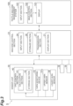
FIG. 3 is a block diagram illustrating a functional configuration and the like of a management system for an amount of waste yarn; -
FIG. 4 is a factor table illustrating examples of yarn breakage factors related to an upper yarn; -
FIG. 5 is a factor table illustrating examples of yarn breakage factors related to a lower yarn; -
FIG. 6 is a factor table illustrating examples of yarn breakage factors of the upper yarn and the lower yarn as a whole; -
FIG. 7 is a display example of a waste yarn weight and the like in a display section of a machine control section (or textile machine management system); -
FIG. 8 is a display example of a waste yarn weight and the like in a display section of a machine control section (or textile machine management system); -
FIG. 9 is a block diagram illustrating a functional configuration and the like of a management system for an amount of waste yarn according to a first modification; and -
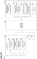
FIG. 10 is a block diagram illustrating a functional configuration and the like of a management system for an amount of waste yarn according to a second modification. - Hereinafter, an embodiment of the present disclosure will be described with reference to the drawings. In the description of the drawings, the same elements are denoted by the same reference numerals, and redundant description is omitted.
- As illustrated in
FIG. 1 , an automatic winder (yarn winding machine) 3 is a device that pulls out a yarn Y from ayarn supplying bobbin 11B having a yarn end disposed inside a windingtube 12 and winds the yarn Y as a package P. Theautomatic winder 3 includes anend frame 20, a plurality of (for example, 24) winder units (yarn winding units) 30, and a doffingcart 45. Theend frame 20 is provided with amachine control section 23. Themachine control section 23 controls an operation of theautomatic winder 3. Themachine control section 23 has adisplay section 21 such as a display and anoperating section 22 such as an input key. Thedisplay section 21 displays an operation status and the like of eachwinder unit 30. The operatingsection 22 is configured to set an operating condition of eachwinder unit 30 by an operator, and the like. - The
machine control section 23 is configured by a central processing unit (CPU), a read only memory (ROM), a random access memory (RAM), and the like. Themachine control section 23 executes various types of control processing in theautomatic winder 3. Such various types of control processing is performed, for example, by loading a program stored in the ROM onto the RAM and executing the program by the CPU. - The
winder units 30 are arranged in one direction, and unwind the yarn Y from theyarn supplying bobbin 11B disposed in theyarn supplying section 9 to form the package P. As illustrated inFIG. 2 , thewinder unit 30 has a windingdevice 31, atension applying device 32, ayarn monitoring device 33, an upperyarn catching device 34, a loweryarn catching device 35, ayarn joining device 36, and a unit control section 40 (seeFIGS. 1 and3 ). - The
yarn supplying section 9 supports theyarn supplying bobbin 11B. Theyarn supplying section 9 can supply the yarn Y unwound from theyarn supplying bobbin 11B. The windingdevice 31 winds the yarn Y supplied from theyarn supplying section 9 to form the package P. The windingdevice 31 has acradle 31a and a windingdrum 31b. Thecradle 31a supports the package P. The windingdrum 31b rotates the package P while traversing the yarn Y. Thus, the yarn Y is wound from theyarn supplying bobbin 11B set at a predetermined position to form the package P. Thetension applying device 32 applies predetermined tension on the yarn Y travelling from theyarn supplying bobbin 11B to the package P. - The
yarn monitoring device 33 monitors the travelling yarn Y to detect a state (yarn defects such as thickness abnormality of yarn Y or mixture of foreign substances in yarn Y) of the yarn. When the yarn defect is detected, the yarn Y is cut by a separately provided cutter. When the yarn Y is cut, the upperyarn catching device 34 catches the yarn end of the yarn Y on the package P side and guides the yarn end to theyarn joining device 36. When the yarn Y is cut, the loweryarn catching device 35 catches the yarn end of the yarn Y on theyarn supplying bobbin 11B side and guides the yarn end to theyarn joining device 36. - The
yarn joining device 36 joins the upper yarn and the lower yarn formed by disconnecting the yarn Y between theyarn supplying section 9 and the windingdevice 31. Theyarn joining device 36 connects the upper yarn, which is the yarn end on the package P side guided by the upperyarn catching device 34, and the lower yarn, which is the yarn end on theyarn supplying bobbin 11B side guided by the loweryarn catching device 35. Theyarn joining device 36 performs a yarn joining operation by twisting the upper yarn and the lower yarn using, for example, an injection force of air. - The
unit control section 40 is configured with a CPU, a ROM, a RAM, and the like. Theunit control section 40 executes various types of control processing in thewinder unit 30. Such various types of control processing is performed, for example, by loading a program stored in the ROM onto the RAM and executing the program by the CPU. - In each
winder unit 30 in theautomatic winder 3 of the present embodiment, yarn breakage occurs due to various factors. In addition to the yarn breakage by theyarn monitoring device 33 described above, the cause of the yarn breakage includes yarn breakage by system cut (artificially stopped work by operator, that is, artificial operation), yarn breakage (tension breakage) caused by fluctuation in tension of the yarn Y, and yarn breakage by replacement (cup change) of theyarn supplying bobbin 11B in theyarn supplying section 9. - When the yarn breakage occurs, the yarn joining operation is performed in the
yarn joining device 36, and at this time, the yarn Y of a predetermined length (or predetermined amount) is removed. More specifically, the inside of pipes of the upperyarn catching device 34 and the loweryarn catching device 35 are coupled to a negative pressure source, and after the yarn joining operation is performed in theyarn joining device 36, the yarn end portions of the upper yarn and the lower yarn sucked in the upperyarn catching device 34 and the loweryarn catching device 35 are sucked. The length of the upper yarn or the lower yarn thus removed is assumed to be substantially constant in each yarn joining operation except after the cutting by the detection of the defect continuing in a long range. That is, the length of the upper yarn or the lower yarn to be removed corresponds to a length from the yarn end of the upper yarn or the lower yarn to a twist point (connected portion). - As illustrated in
FIG. 1 , ablower box 80 is provided in a part of theend frame 20, and a blower as a negative pressure source is installed in theblower box 80. The waste yarn collected through a blower duct is stored in acotton collecting box 19. - As illustrated in
FIG. 3 , theunit control section 40 of eachwinder unit 30 includes acalculation section 41 configured to calculate a waste yarn amount generated at the time of yarn joining operation in theyarn joining device 36 for each yarn breakage factor. Thecalculation section 41 calculates a waste yarn amount of the upper yarn generated in the upper yarn for each yarn breakage factor. Thecalculation section 41 calculates a waste yarn amount of the lower yarn generated in the lower yarn for each yarn breakage factor. -
FIG. 4 is a factor table illustrating examples of yarn breakage factors related to an upper yarn. For each of the upper yarn and the lower yarn, thecalculation section 41 calculates a suction length (length) for each item (each yarn breakage factor) shown in the table. Thecalculation section 41 calculates a suction amount (weight) for each item (each yarn breakage factor) shown in the table by multiplying the suction length by the weight per unit length. Thestorage section 42 stores a weight per unit length according to a yarn type or yarn count information. Thestorage section 42 stores a calculation result (measurement result) of the waste yarn amount in thecalculation section 41. - The
storage section 42 stores (inputs) a past actual measurement value of the waste yarn amount generated in one yarn joining operation. In the case of the upper yarn, thecalculation section 41 calculates the waste yarn amount based on a set value. Thecalculation section 41 calculates a cumulative waste yarn length or waste yarn amount by multiplying the waste yarn amount generated from the upper yarn in one yarn joining operation (one cutting operation) and a number of yarn joining operations. The waste yarn amount generated from the upper yarn used here can be calculated from a set value of a number of rotations of reversely rotating the package so that a necessary length is pulled out after a yarn end detection sensor provided in the upperyarn catching device 34 detects the sucked upper yarn. In the case of the lower yarn, the waste yarn amount is calculated based on the past actual measurement value. Thecalculation section 41 calculates a cumulative waste yarn length or waste yarn amount by multiplying an actual measurement value of the waste yarn amount generated from the lower yarn in one yarn joining operation (one cutting operation) and the number of yarn joining operations. The above-described actual measurement value is a value obtained in advance by actual measurement, and can be said to be an empirical value. Specifically, the actual measurement value is obtained by measuring the length of the lower yarn actually sucked and removed. The actual measurement value is obtained separately for each of the upper yarn and the lower yarn. Since the actual measurement value serves as a reference for calculating the waste yarn amount, the "past actual measurement value" can also be referred to as an "inputted reference value". In the embodiment described above, the waste yarn amount is calculated using the set value for the upper yarn, and the waste yarn amount is obtained using the actual measurement value for the lower yarn, but the waste yarn amount can also be obtained using the actual measurement values for both the upper yarn and the lower yarn. - For the yarn breakage factors of
items 3 to 14 in the table illustrated inFIG. 4 , when each factor is a short defect (appearing only in a short section of the yarn Y), the calculation based on the actual measurement value is adopted. The calculation based on the actual measurement value is also adopted for the yarn breakage factors ofitems 15 to 17. Thecalculation section 41 regards these yarn breakage factors as a yarn breakage factor that generates a certain amount of waste yarn in one yarn breakage, and calculates the waste yarn amount for each yarn breakage factor by multiplying the past actual measurement value and the number of yarn joining operations. - In the
unit control section 40, when any yarn joining operation is performed, thecalculation section 41 determines to which item (yarn breakage factor) illustrated in the table it belongs based on the signal from theyarn monitoring device 33 or the control status of theunit control section 40 itself. That is, thecalculation section 41 determines which yarn breakage factor causes yarn disconnecting when the yarn joining operation is performed. Information related to the type of the yarn breakage factor, the time when the yarn joining operation is performed, and the like is stored in thestorage section 42. Regarding the cut (yarn breakage factors ofitems 3 to 14) in theyarn monitoring device 33, whether each factor is a short defect is determined based on the information received from theyarn monitoring device 33. - For the yarn breakage factors of
items 3 to 14 in the table illustrated inFIG. 4 , another calculation is performed when each factor is a long defect (appearing over a relatively long section of the yarn Y). For example, the L cut (No. 5) and the H cut (No. 11) include a yarn breakage factor of a long defect. In such a case, thecalculation section 41 determines that the factor is the yarn breakage factor caused by a specific state, cuts and removes a part of the yarn Y based on the length of the yarn Y wound by the windingdevice 31 until the specific state disappears after the specific state is found in theyarn monitoring device 33, and calculates the waste yarn amount. In the setting of the present embodiment, the long defect is determined as described above, but the recognition of the long defect can be changed according to the setting of theyarn monitoring device 33. - More specifically, the upper yarn catching device 34 (
FIG. 2 ) is provided with a transparent window at a position of a pipedistal end portion 34a, and when the upperyarn catching device 34 is positioned at the lifted position, the transparent window faces anupper yarn sensor 31c (seeFIG. 3 ) fixed in proximity to the windingdrum 31b. Thecalculation section 41 detects the presence of the upper yarn in the upperyarn catching device 34 by theupper yarn sensor 31c, and then calculates the waste yarn amount based on the number of times the windingdrum 31b is reversely rotated. The number of times the windingdrum 31b is reversely rotated is also determined based on a signal (signal indicating the length in which the yarn defect exists) sent from theyarn monitoring device 33. The method described inJapanese Unexamined Patent Publication No. 2020-143397 - With respect to the cup change of the item No. 17 in the table illustrated in
FIG. 4 , the waste yarn amount is counted by the method described above when the presence of the lower yarn is detected by thelower yarn sensor 38, but the waste yarn amount is not counted when the presence of the lower yarn is not detected by alower yarn sensor 38. -
FIG. 5 is a factor table illustrating examples of yarn breakage factors related to the lower yarn, andFIG. 6 is a factor table illustrating examples of yarn breakage factors of the upper yarn and the lower yarn as a whole. For each item illustrated inFIGS. 5 and6 , calculation is performed by thecalculation section 41 similarly to the item in the table illustrated inFIG. 4 . - Although not illustrated in the table of
FIG. 5 , regarding the lower yarn, "lower yarn sucking" can also be exemplified as an example of the yarn breakage factor. This means processing of forcibly sucking and removing the cut lower yarn by the loweryarn catching device 35. The "lower yarn sucking" is executed when the quality of theyarn supplying bobbin 11B is poor. Also in this case, the waste yarn amount is calculated based on the suction time. The suction time is a time during which suction was performed, and the suction length of the yarn sucked by the loweryarn catching device 35 per unit time is used. As the suction length, an empirical value measured in advance is used. - As illustrated in
FIG. 3 , themachine control section 23 includes aninput section 24 that receives input of data of a waste yarn amount for each yarn breakage factor calculated by thecalculation section 41, and astorage section 26 that stores a calculation result (measurement result) of the waste yarn amount in thecalculation section 41. Thedisplay section 21 of themachine control section 23 displays the waste yarn amount for each yarn breakage factor stored in thestorage section 26. -
FIGS. 7 and8 illustrate display examples on thedisplay section 21, respectively. As illustrated inFIG. 7 , the operator can refer to the past data of the waste yarn amount in theautomatic winder 3 by selecting a waste yarnamount selection tab 110. When the operator presses atotal selection button 113, data related to the total waste yarn amount of the upper yarn and the lower yarn can be displayed. A display target range (a machine, a shift, or the like) can be selected in a displaytarget selection button 120. The operator can display the weight of the waste yarn for each yarn breakage factor by selecting the four buttons included in afactor selection section 112. Afirst factor button 112a is a button for selecting system cut. Asecond factor button 112b is a button for selecting theyarn monitoring device 33 cut. Athird factor button 112c is a button for selecting tension breakage. Afourth factor button 112d is a button for selecting a cup change. In the example ofFIG. 7 , the weight of the waste yarn is displayed for the yarn breakage factors ofitems 31 to 45 illustrated inFIG. 5 . The screen includes aweight display section 130 and atrend display section 140 for waste yarns for each unit. - As illustrated in
FIG. 8 , the operator can display data related to a waste yarn amount of only an upper yarn by pressing an upperyarn selection button 114. In the example illustrated inFIG. 8 , the waste yarn amount (weight) for each yarn breakage factor of the upper yarn is displayed. - In the present embodiment, as illustrated in
FIG. 3 , the waste yarn amount can be managed not only in theautomatic winder 3 but also in a place different from the site. A management system S for an amount of waste yarn includes anautomatic winder 3 having a plurality ofwinder units 30, amachine control section 23, and a textilemachine management system 100. The textilemachine management system 100 is connected to be capable of communicating information with themachine control section 23. The textilemachine management system 100 may be, for example, a management device such as a host server of a factory, an electric bulletin board, a signage board, or a maintenance server of a management company, or may be a mobile terminal carried by an administrator. Furthermore, the textilemachine management system 100 may transmit data regarding the waste yarn amount to an operator terminal by email. The textilemachine management system 100 may be capable of wirelessly communicating information with themachine control section 23. - The
machine control section 23 has atransmission section 27 configured to transmit the data of the waste yarn amount for each yarn breakage factor stored in thestorage section 26 to the textilemachine management system 100. Aninput section 101 of the textilemachine management system 100 receives input of the received data. Amain control section 102 of the textilemachine management system 100 may determine the improvement instruction based on the waste yarn amount for each yarn breakage factor. Similarly to thedisplay section 21, adisplay 103 of the textilemachine management system 100 may display the waste yarn amount for each yarn breakage factor. - Furthermore, by managing the waste yarn amount for each yarn breakage factor with the textile
machine management system 100, the waste yarn amount for each yarn breakage factor of theautomatic winder 3 can be compared with the waste yarn amount for each yarn breakage factor of anotherautomatic winder 3 operating under the same condition. Furthermore, the waste yarn amount for each yarn breakage factor generated in the plurality ofautomatic winders 3 can be managed in total for each yarn breakage factor. By performing the management in this manner, theautomatic winder 3 having a poor operation status can be specified, and theautomatic winder 3 can be used as an index for specifying a factor of the deterioration in the operation status. - According to the
winder unit 30, the waste yarn amount is calculated for each yarn breakage factor by thecalculation section 41. Therefore, the waste yarn amount can be measured for each yarn breakage factor, and it is possible to analyze which yarn breakage factor causes a large waste yarn amount. - The
calculation section 41 calculates a waste yarn amount of the upper yarn, which is a waste yarn amount generated in the upper yarn, for each yarn breakage factor, and calculates a waste yarn amount of the lower yarn, which is a waste yarn amount generated in the lower yarn, for each yarn breakage factor. Thus, each of the waste yarn amount of the upper yarn and the waste yarn amount of the lower yarn can be measured for each yarn breakage factor. - The
calculation section 41 calculates a waste yarn amount for at least one of yarn breakage by theyarn monitoring device 33, yarn breakage by system cut, yarn breakage due to fluctuation in tension of the yarn, and yarn breakage by replacement of the yarn supplying bobbin in theyarn supplying section 9 as the yarn breakage factor. Thus, the yarn breakage factor can be finely classified and managed, and the hard waste in thewinder unit 30 can be reduced. - With respect to a yarn breakage factor caused by a specific state of the yarn monitored by the yarn monitoring device, the
calculation section 41 calculates a waste yarn amount based on the length of the yarn wound by the winding device until the specific state disappears after the specific state is found. Thus, the waste yarn amount can be grasped for the yarn breakage factor occurring in the long section of the yarn. - The
calculation section 41 calculates a waste yarn amount based on the past actual measurement value for the yarn breakage factor of generating a certain amount of waste yarn in one yarn breakage. Among the yarn breakage factors, there are many factors in which the length (yarn section) of the yarn to be removed is substantially limited in accordance with the size of the upperyarn catching device 34 or the loweryarn catching device 35 for both the upper yarn and the lower yarn. By calculating the waste yarn amount based on the past actual measurement value, the waste yarn amount for such a yarn breakage factor can be accurately grasped. - In the
automatic winder 3, the operator refers to the waste yarn amount for each yarn breakage factor in thedisplay section 21, thereby reducing the hard waste in thewinder unit 30. - According to the management system S for an amount of waste yarn including the textile
machine management system 100, the administrator can manage, analyze, or monitor the waste yarn amount for each yarn breakage factor at a place different from the site where the yarn winding unit is installed. The administrator can more appropriately manage the yarn winding unit by referring to the waste yarn amount for each yarn breakage factor in the display section, and can consider improvement of the yarn winding unit. The administrator can also take an improvement measure in accordance with the improvement instruction determined by the textilemachine management system 100. - Although the embodiment of the present disclosure has been described above, the present invention is not limited to the above embodiment. For example, the function of the
calculation section 41 in the above embodiment may be provided in themachine control section 23 or the textilemachine management system 100.FIG. 9 is a block diagram illustrating a functional configuration and the like of a management system SA for an amount of waste yarn according to a first modification. In the management system SA for an amount of waste yarn illustrated inFIG. 9 , not awinder unit 30A but amachine control section 23A includes acalculation section 25 configured to calculate a waste yarn amount generated at the time of a yarn joining operation in theyarn joining device 36 for each yarn breakage factor. Thedisplay section 21 of themachine control section 23A displays a management screen (waste yarn amount for each yarn breakage factor) similar to thedisplay section 21 in themachine control section 23. Thedisplay 103 of the textilemachine management system 100A displays the waste yarn amount for each yarn breakage factor. The waste yarn amount for each yarn breakage factor may be displayed on only one of thedisplay section 21 and thedisplay 103. - Even with the management system SA for an amount of waste yarn according to the first modification, the administrator can manage, analyze, or monitor the waste yarn amount for each yarn breakage factor at a place different from the site where the
winder unit 30A is installed. The calculation of the waste yarn amount in eachwinder unit 30A is unnecessary. By referring to the waste yarn amount for each yarn breakage factor in thedisplay section 21, the operator can reduce the hard waste in thewinder unit 30A. Furthermore, the administrator can more appropriately manage and consider the improvement of thewinder unit 30A by referring to the waste yarn amount for each yarn breakage factor in thedisplay 103. Furthermore, themachine control section 23A performs up to calculation of the waste yarn amount, and the stored data is transmitted to the textilemachine management system 100A. Therefore, the data is organized and integrated on theautomatic winder 3 side, and overall management in the textilemachine management system 100A becomes possible. -
FIG. 10 is a block diagram illustrating a functional configuration and the like of a management system SB for an amount of waste yarn according to a second modification. In the management system SB for an amount of waste yarn illustrated inFIG. 10 , not awinder unit 30B or amachine control section 23B but a textilemachine management system 100B includes acalculation section 104 configured to calculate the waste yarn amount generated at the time of the yarn joining operation in theyarn joining device 36 for each yarn breakage factor. The textilemachine management system 100B includes aninput section 24 that receives input of data of a waste yarn amount for each yarn breakage factor calculated by thecalculation section 41, a main control section 102B, and adisplay 103. The main control section 102B includes acalculation section 104, astorage section 105 that stores a calculation result (measurement result) of the waste yarn amount in thecalculation section 104, and adisplay control section 106. Thedisplay 103 is controlled by thedisplay control section 106, and displays a management screen (waste yarn amount for each yarn breakage factor) similar to thedisplay section 21 in themachine control section 23. - Even with the management system SB for an amount of waste yarn according to the second modification, the administrator can manage, analyze, or monitor the waste yarn amount for each yarn breakage factor at a place different from the site where the
winder unit 30B is installed. Specifically, the administrator can more appropriately manage and consider the improvement of thewinder unit 30A by referring to the waste yarn amount for each yarn breakage factor in thedisplay 103. The calculation of the waste yarn amount in eachwinder unit 30B and eachautomatic winder 3 is unnecessary. - In the management systems SA and SB for an amount of waste yarn according to the various modifications described above, information such as the number of yarn joining operations, the number of failed yarn joining operations, what type of yarn joining operation was used for dealing with the yarn defect, and the like is transmitted from each
winder unit 30 to a downstream device (machine control sections machine management systems - As described above, as exemplified in the embodiment and various modifications, in the management system for an amount of waste yarn of the present invention, any one of the yarn winding unit, the machine control section, and the textile machine management system may include a calculation section configured to calculate the waste yarn amount generated at the time of yarn joining operation in the yarn joining device for each yarn breakage factor. At least one of the yarn winding unit, the machine control section, or the textile machine management system may have a display section configured to display the waste yarn amount for each yarn breakage factor calculated by the calculation section. The management system for an amount of waste yarn may include a terminal or the like such as a tablet, and the terminal or the like may be caused to display the waste yarn amount for each yarn breakage factor. In this case, the control section including the calculation section and the storage section transmits data of the waste yarn amount for each yarn breakage factor to the terminal or the like as information, and causes the terminal or the like to display the waste yarn amount for each yarn breakage factor.
- The present invention can also be applied to a textile machine other than the
winder unit 30. For example, the present invention may be used to grasp a waste yarn amount in a spinning machine.
Claims (14)
- A yarn winding unit comprising:a yarn supplying section configured to support a yarn supplying bobbin and capable of supplying a yarn unwound from the supported yarn supplying bobbin;a winding device configured to wind the yarn supplied from the yarn supplying section to form a package;a yarn joining device configured to perform a yarn joining operation of an upper yarn and a lower yarn formed by disconnecting a yarn between the yarn supplying section and the winding device; anda calculation section configured to determine which yarn breakage factor causes yarn disconnecting when the yarn joining operation is performed, and calculate a waste yarn amount generated at the time of the yarn joining operation in the yarn joining device for each yarn breakage factor.
- The yarn winding unit according to claim 1, wherein the calculation section calculates a waste yarn amount of an upper yarn, which is the waste yarn amount generated in the upper yarn, for each yarn breakage factor, and calculates a waste yarn amount of a lower yarn, which is the waste yarn amount generated in the lower yarn, for each yarn breakage factor.
- The yarn winding unit according to claim 1 or 2, further comprising:a yarn monitoring device configured to monitor a state of the yarn, whereinthe calculation section calculates the waste yarn amount for at least one of yarn breakage caused by the yarn monitoring device, yarn breakage caused by an artificial operation of an operator, yarn breakage caused by fluctuation in tension of the yarn, and yarn breakage caused by replacement of the yarn supplying bobbin in the yarn supplying section, as the yarn breakage factor.
- The yarn winding unit according to claim 3, wherein the calculation section calculates, with respect to a yarn breakage factor caused by a specific state of the yarn monitored by the yarn monitoring device, the waste yarn amount based on a length of the yarn wound by the winding device until the specific state disappears after the specific state is found.
- The yarn winding unit according to any one of claims 1 to 4, wherein the calculation section calculates the waste yarn amount based on an inputted reference value for a yarn breakage factor of generating a certain amount of waste yarn in one yarn breakage.
- A yarn winding machine comprising:at least one yarn winding unit according to any one of claims 1 to 5; anda machine control section configured to control the yarn winding unit, whereinthe yarn winding unit or the machine control section includes a storage section configured to store a calculation result of the waste yarn amount in the calculation section, andthe machine control section includes a display section configured to display the waste yarn amount for each yarn breakage factor stored in the storage section.
- A management system for an amount of waste yarn, comprising:at least one yarn winding machine according to claim 6; anda textile machine management system capable of communicating information with the machine control section, whereinthe machine control section includes a transmission section configured to transmit data of the waste yarn amount for each yarn breakage factor stored in the storage section to the textile machine management system as the information.
- The management system for an amount of waste yarn according to claim 7, wherein the textile machine management system includes a display section configured to display the waste yarn amount for each yarn breakage factor stored in the storage section.
- The management system for an amount of waste yarn according to claim 7 or 8, wherein the textile machine management system determines an improvement instruction based on the waste yarn amount for each yarn breakage factor stored in the storage section.
- A management system for an amount of waste yarn, comprising:a yarn winding unit includinga yarn supplying section configured to support a yarn supplying bobbin and capable of supplying a yarn unwound from the supported yarn supplying bobbin,a winding device configured to wind the yarn supplied from the yarn supplying section to form a package, anda yarn joining device configured to perform a yarn joining operation of an upper yarn and a lower yarn formed by disconnecting a yarn between the yarn supplying section and the winding device;a machine control section configured to control the yarn winding unit; anda textile machine management system capable of communicating information with the machine control section, whereinany one of the yarn winding unit, the machine control section, and the textile machine management system includesa calculation section configured to determine which yarn breakage factor causes yarn disconnecting when the yarn joining operation is performed, and calculate a waste yarn amount generated at the time of the yarn joining operation in the yarn joining device for each yarn breakage factor.
- The management system for an amount of waste yarn according to claim 10, wherein at least one of the yarn winding unit, the machine control section, or the textile machine management system includes a display section configured to display the waste yarn amount for each yarn breakage factor calculated by the calculation section.
- The management system for an amount of waste yarn according to claim 11, whereinthe machine control section includesthe calculation section, andthe display section.
- The management system for an amount of waste yarn according to claim 11, whereina textile machine management system includesthe calculation section, andthe display section.
- The management system for an amount of waste yarn according to claim 11, whereinthe machine control section includesthe calculation section,a storage section configured to store a calculation result of the waste yarn amount in the calculation section, anda transmission section configured to transmit data of the waste yarn amount for each yarn breakage factor stored in the storage section to the textile machine management system as the information, andthe textile machine management system includes the display section.
Applications Claiming Priority (1)
| Application Number | Priority Date | Filing Date | Title |
|---|---|---|---|
| JP2023021081A JP2024115401A (en) | 2023-02-14 | 2023-02-14 | Yarn winding unit, yarn winding machine, and waste yarn amount management system |
Publications (1)
| Publication Number | Publication Date |
|---|---|
| EP4417560A1 true EP4417560A1 (en) | 2024-08-21 |
Family
ID=89854537
Family Applications (1)
| Application Number | Title | Priority Date | Filing Date |
|---|---|---|---|
| EP24156300.6A Pending EP4417560A1 (en) | 2023-02-14 | 2024-02-07 | Yarn winding unit, yarn winding machine and management system for amount of waste yarn |
Country Status (3)
| Country | Link |
|---|---|
| EP (1) | EP4417560A1 (en) |
| JP (1) | JP2024115401A (en) |
| CN (1) | CN118495259A (en) |
Citations (3)
| Publication number | Priority date | Publication date | Assignee | Title |
|---|---|---|---|---|
| EP2644553A2 (en) * | 2012-03-28 | 2013-10-02 | Murata Machinery, Ltd. | Yarn defect classifying device and method and yarn winding machine |
| EP3705431A1 (en) * | 2019-03-06 | 2020-09-09 | Murata Machinery, Ltd. | Waste yarn emission amount output device and textile machine |
| EP3964467A1 (en) * | 2020-09-04 | 2022-03-09 | Murata Machinery, Ltd. | Textile machine and waste yarn amount calculation method |
-
2023
- 2023-02-14 JP JP2023021081A patent/JP2024115401A/en active Pending
-
2024
- 2024-01-29 CN CN202410118563.4A patent/CN118495259A/en active Pending
- 2024-02-07 EP EP24156300.6A patent/EP4417560A1/en active Pending
Patent Citations (4)
| Publication number | Priority date | Publication date | Assignee | Title |
|---|---|---|---|---|
| EP2644553A2 (en) * | 2012-03-28 | 2013-10-02 | Murata Machinery, Ltd. | Yarn defect classifying device and method and yarn winding machine |
| EP3705431A1 (en) * | 2019-03-06 | 2020-09-09 | Murata Machinery, Ltd. | Waste yarn emission amount output device and textile machine |
| JP2020143397A (en) | 2019-03-06 | 2020-09-10 | 村田機械株式会社 | Output device for generation amount of waste thread, and textile machine |
| EP3964467A1 (en) * | 2020-09-04 | 2022-03-09 | Murata Machinery, Ltd. | Textile machine and waste yarn amount calculation method |
Also Published As
| Publication number | Publication date |
|---|---|
| JP2024115401A (en) | 2024-08-26 |
| CN118495259A (en) | 2024-08-16 |
Similar Documents
| Publication | Publication Date | Title |
|---|---|---|
| US11319649B2 (en) | Ring spinning system and method for operating | |
| EP2573236A2 (en) | Textile machine and textile machine system | |
| JPH01221524A (en) | Quality control system in spinning mill | |
| JPH0555428B2 (en) | ||
| EP2664571A2 (en) | Yarn winding apparatus | |
| JP2013044066A (en) | Textile machine and information transmission system of textile machine | |
| JP5805194B2 (en) | Textile machinery | |
| EP3293295A1 (en) | Measurement system for a machine that processes a continuous strand like textile material | |
| CN108285062B (en) | Yarn information acquisition device, yarn winding machine, and textile machine system | |
| US20210164132A1 (en) | Automatic ring spinning system and method for automatically operating same | |
| CN103510217A (en) | Textile machinery and periodic unevenness detecting method therein | |
| WO2023066544A1 (en) | An electronic device for adjusting operational parameters of a winding machine of a spinning mill and a method for adjusting the same | |
| JP2024115401A (en) | Yarn winding unit, yarn winding machine, and waste yarn amount management system | |
| EP3964467B1 (en) | Textile machine | |
| JP2021038476A (en) | Management device of spinning machine and spinning machine equipped with management device | |
| CN111661706B (en) | Waste yarn output device and textile machine | |
| EP3919426A1 (en) | Yarn winding machine and spinning system | |
| JPH03120159A (en) | Data collecting device for winder | |
| EP3686330B1 (en) | Spinning method, spinning machine, and spinning program | |
| EP3378815B1 (en) | Yarn winding machine | |
| CN119100206A (en) | Fiber Machinery Systems | |
| CN112593316B (en) | Computing device, air spinning machine, and method for outputting generation amount of lint | |
| JP2024176059A (en) | Textile Machinery Systems | |
| EP3611120B1 (en) | Condition display device, and thread-winding apparatus | |
| JP2024081978A (en) | Management Device |
Legal Events
| Date | Code | Title | Description |
|---|---|---|---|
| PUAI | Public reference made under article 153(3) epc to a published international application that has entered the european phase |
Free format text: ORIGINAL CODE: 0009012 |
|
| STAA | Information on the status of an ep patent application or granted ep patent |
Free format text: STATUS: THE APPLICATION HAS BEEN PUBLISHED |
|
| AK | Designated contracting states |
Kind code of ref document: A1 Designated state(s): AL AT BE BG CH CY CZ DE DK EE ES FI FR GB GR HR HU IE IS IT LI LT LU LV MC ME MK MT NL NO PL PT RO RS SE SI SK SM TR |
|
| STAA | Information on the status of an ep patent application or granted ep patent |
Free format text: STATUS: REQUEST FOR EXAMINATION WAS MADE |
|
| 17P | Request for examination filed |
Effective date: 20250116 |