EP4417547A1 - Supply apparatus - Google Patents
Supply apparatus Download PDFInfo
- Publication number
- EP4417547A1 EP4417547A1 EP24153560.8A EP24153560A EP4417547A1 EP 4417547 A1 EP4417547 A1 EP 4417547A1 EP 24153560 A EP24153560 A EP 24153560A EP 4417547 A1 EP4417547 A1 EP 4417547A1
- Authority
- EP
- European Patent Office
- Prior art keywords
- conveyance path
- articles
- supply
- blocker
- supply apparatus
- Prior art date
- Legal status (The legal status is an assumption and is not a legal conclusion. Google has not performed a legal analysis and makes no representation as to the accuracy of the status listed.)
- Pending
Links
Images




Classifications
-
- B—PERFORMING OPERATIONS; TRANSPORTING
- B65—CONVEYING; PACKING; STORING; HANDLING THIN OR FILAMENTARY MATERIAL
- B65B—MACHINES, APPARATUS OR DEVICES FOR, OR METHODS OF, PACKAGING ARTICLES OR MATERIALS; UNPACKING
- B65B57/00—Automatic control, checking, warning, or safety devices
- B65B57/10—Automatic control, checking, warning, or safety devices responsive to absence, presence, abnormal feed, or misplacement of articles or materials to be packaged
- B65B57/14—Automatic control, checking, warning, or safety devices responsive to absence, presence, abnormal feed, or misplacement of articles or materials to be packaged and operating to control, or stop, the feed of articles or material to be packaged
-
- B—PERFORMING OPERATIONS; TRANSPORTING
- B65—CONVEYING; PACKING; STORING; HANDLING THIN OR FILAMENTARY MATERIAL
- B65G—TRANSPORT OR STORAGE DEVICES, e.g. CONVEYORS FOR LOADING OR TIPPING, SHOP CONVEYOR SYSTEMS OR PNEUMATIC TUBE CONVEYORS
- B65G47/00—Article or material-handling devices associated with conveyors; Methods employing such devices
- B65G47/52—Devices for transferring articles or materials between conveyors i.e. discharging or feeding devices
- B65G47/72—Devices for transferring articles or materials between conveyors i.e. discharging or feeding devices transferring materials in bulk from one conveyor to several conveyors, or vice versa
-
- B—PERFORMING OPERATIONS; TRANSPORTING
- B65—CONVEYING; PACKING; STORING; HANDLING THIN OR FILAMENTARY MATERIAL
- B65B—MACHINES, APPARATUS OR DEVICES FOR, OR METHODS OF, PACKAGING ARTICLES OR MATERIALS; UNPACKING
- B65B35/00—Supplying, feeding, arranging or orientating articles to be packaged
-
- B—PERFORMING OPERATIONS; TRANSPORTING
- B65—CONVEYING; PACKING; STORING; HANDLING THIN OR FILAMENTARY MATERIAL
- B65G—TRANSPORT OR STORAGE DEVICES, e.g. CONVEYORS FOR LOADING OR TIPPING, SHOP CONVEYOR SYSTEMS OR PNEUMATIC TUBE CONVEYORS
- B65G27/00—Jigging conveyors
-
- B—PERFORMING OPERATIONS; TRANSPORTING
- B65—CONVEYING; PACKING; STORING; HANDLING THIN OR FILAMENTARY MATERIAL
- B65G—TRANSPORT OR STORAGE DEVICES, e.g. CONVEYORS FOR LOADING OR TIPPING, SHOP CONVEYOR SYSTEMS OR PNEUMATIC TUBE CONVEYORS
- B65G43/00—Control devices, e.g. for safety, warning or fault-correcting
- B65G43/08—Control devices operated by article or material being fed, conveyed or discharged
-
- B—PERFORMING OPERATIONS; TRANSPORTING
- B65—CONVEYING; PACKING; STORING; HANDLING THIN OR FILAMENTARY MATERIAL
- B65G—TRANSPORT OR STORAGE DEVICES, e.g. CONVEYORS FOR LOADING OR TIPPING, SHOP CONVEYOR SYSTEMS OR PNEUMATIC TUBE CONVEYORS
- B65G47/00—Article or material-handling devices associated with conveyors; Methods employing such devices
- B65G47/74—Feeding, transfer, or discharging devices of particular kinds or types
- B65G47/76—Fixed or adjustable ploughs or transverse scrapers
- B65G47/766—Adjustable ploughs or transverse scrapers
-
- B—PERFORMING OPERATIONS; TRANSPORTING
- B65—CONVEYING; PACKING; STORING; HANDLING THIN OR FILAMENTARY MATERIAL
- B65G—TRANSPORT OR STORAGE DEVICES, e.g. CONVEYORS FOR LOADING OR TIPPING, SHOP CONVEYOR SYSTEMS OR PNEUMATIC TUBE CONVEYORS
- B65G47/00—Article or material-handling devices associated with conveyors; Methods employing such devices
- B65G47/74—Feeding, transfer, or discharging devices of particular kinds or types
- B65G47/78—Troughs having discharge openings and closures
-
- G—PHYSICS
- G01—MEASURING; TESTING
- G01G—WEIGHING
- G01G13/00—Weighing apparatus with automatic feed or discharge for weighing-out batches of material
- G01G13/02—Means for automatically loading weigh pans or other receptacles, e.g. disposable containers, under control of the weighing mechanism
- G01G13/022—Material feeding devices
- G01G13/026—Material feeding devices by mechanical conveying means, e.g. belt or vibratory conveyor
-
- G—PHYSICS
- G01—MEASURING; TESTING
- G01G—WEIGHING
- G01G19/00—Weighing apparatus or methods adapted for special purposes not provided for in the preceding groups
- G01G19/387—Weighing apparatus or methods adapted for special purposes not provided for in the preceding groups for combinatorial weighing, i.e. selecting a combination of articles whose total weight or number is closest to a desired value
- G01G19/393—Weighing apparatus or methods adapted for special purposes not provided for in the preceding groups for combinatorial weighing, i.e. selecting a combination of articles whose total weight or number is closest to a desired value using two or more weighing units
-
- B—PERFORMING OPERATIONS; TRANSPORTING
- B65—CONVEYING; PACKING; STORING; HANDLING THIN OR FILAMENTARY MATERIAL
- B65G—TRANSPORT OR STORAGE DEVICES, e.g. CONVEYORS FOR LOADING OR TIPPING, SHOP CONVEYOR SYSTEMS OR PNEUMATIC TUBE CONVEYORS
- B65G11/00—Chutes
- B65G11/20—Auxiliary devices, e.g. for deflecting, controlling speed of, or agitating articles or solids
- B65G11/206—Auxiliary devices, e.g. for deflecting, controlling speed of, or agitating articles or solids for bulk
-
- B—PERFORMING OPERATIONS; TRANSPORTING
- B65—CONVEYING; PACKING; STORING; HANDLING THIN OR FILAMENTARY MATERIAL
- B65G—TRANSPORT OR STORAGE DEVICES, e.g. CONVEYORS FOR LOADING OR TIPPING, SHOP CONVEYOR SYSTEMS OR PNEUMATIC TUBE CONVEYORS
- B65G2203/00—Indexing code relating to control or detection of the articles or the load carriers during conveying
- B65G2203/02—Control or detection
- B65G2203/0208—Control or detection relating to the transported articles
- B65G2203/0258—Weight of the article
-
- B—PERFORMING OPERATIONS; TRANSPORTING
- B65—CONVEYING; PACKING; STORING; HANDLING THIN OR FILAMENTARY MATERIAL
- B65G—TRANSPORT OR STORAGE DEVICES, e.g. CONVEYORS FOR LOADING OR TIPPING, SHOP CONVEYOR SYSTEMS OR PNEUMATIC TUBE CONVEYORS
- B65G2811/00—Indexing codes relating to common features for more than one conveyor kind or type
- B65G2811/06—Devices controlling the relative position of articles
- B65G2811/0647—Changing the direction of movement of articles or bulk material
- B65G2811/0657—Deflectors
-
- B—PERFORMING OPERATIONS; TRANSPORTING
- B65—CONVEYING; PACKING; STORING; HANDLING THIN OR FILAMENTARY MATERIAL
- B65G—TRANSPORT OR STORAGE DEVICES, e.g. CONVEYORS FOR LOADING OR TIPPING, SHOP CONVEYOR SYSTEMS OR PNEUMATIC TUBE CONVEYORS
- B65G2811/00—Indexing codes relating to common features for more than one conveyor kind or type
- B65G2811/06—Devices controlling the relative position of articles
- B65G2811/0673—Control of conveying operations
- B65G2811/0678—Determining the path to be followed
Definitions
- the present invention relates to a supply apparatus.
- One of the two methods is a method of controlling supply of weighing targets to each channel with a sorter provided below a single supply apparatus.
- the other of the two methods is a method of supplying weighing targets to the individual distribution table of each channel with two supply apparatuses.
- Patent Literature 1 JP 3209972 U
- a plurality of supply apparatuses requires preparing, and a plurality of distributors following a main supply line are required, leading to a rise in cost as a disadvantage.
- an object of the present invention is to provide a supply apparatus capable of sorting weighing targets efficiently and requiring no intricate mechanism between the supply apparatus and a weighing mechanism, leading to a low installation height.
- a supply apparatus for supplying articles onto two independent distribution tables that each of two adjacent combination weighing mechanisms includes, the supply apparatus including: a conveyer including: a main conveyance path extending in a direction orthogonal to a straight line connecting respective centers of the two independent distribution tables; a first conveyance path connected continuously to the main conveyance path, the first conveyance path allowing the articles to be supplied to one of the two independent distribution tables; and a second conveyance path allowing the articles to be supplied to another of the two independent distribution tables; a blocker disposed at a fork between the main conveyance path, the first conveyance path, and the second conveyance path, the blocker making a switch between a first state where supply of the articles from the main conveyance path to the first conveyance path is blocked and a second state where supply of the articles from the main conveyance path to the second conveyance path is blocked; and a controller that transitions, based on respective conditions of supply of the articles to the two adjacent combination weighing mechanisms, the blocker into at least
- a combination weighing system including weighing mechanisms 1A and 1B and a supply apparatus 10 according to a first embodiment of the present invention will be described below with reference to FIGS. 1 to 3 .
- the supply apparatus 10 supplies articles onto two independent distribution tables 2A and 2B that the two adjacent combination weighing mechanisms 1A and 1B include, respectively.
- the supply apparatus 10 includes a conveyer 100, a blocker 13, and a controller 20.
- the conveyer 100 includes a main conveyance path 11, a first conveyance path 12A, and a second conveyance path 12B.
- the main conveyance path 11 extends in a direction D1 orthogonal to a straight line L1 connecting the respective centers 3A and 3B of the distribution tables 2A and 2B.
- the respective tops 3T1 and 3T2 of the distribution tables 2A and 2B may be identical to the centers 3A and 3B of the distribution tables 2A and 2B, respectively, or may be eccentric to the centers 3A and 3B of the distribution tables 2A and 2B, respectively, as illustrated in FIG. 2 .
- the distribution tables 2A and 2B are each a member that conveys articles supplied by vibrations from a vibrator, circumferentially and outward. In this case, a composition of vibrations causes articles to be conveyed in a spiral on each of the distribution tables 2A and 2B.
- the first conveyance path 12A is connected continuously to the main conveyance path 11 and supplies articles to the distribution table 2A that is one of the two distribution tables 2A and 2B. Meanwhile, the second conveyance path 12B supplies articles to the distribution table 2B that is the other of the two distribution tables 2A and 2B.
- the blocker 13 is disposed at a fork 12 between the main conveyance path 11, the first conveyance path 12A, and the second conveyance path 12B.
- the blocker 13 makes a switch between a first state where supply of articles from the main conveyance path 11 to the first conveyance path 12A is blocked and a second state where supply of articles from the main conveyance path 11 to the second conveyance path 12B is blocked.
- a partition 14 may be provided at the center of the fork 12.
- the blocker 13 may include a first blocker 13A and a second blocker 13B.
- the first blocker 13A blocks supply of articles from the main conveyance path 11 to the first conveyance path 12A.
- the second blocker 13B blocks supply of articles from the main conveyance path 11 to the second conveyance path 12B.
- the first blocker 13A may be achieved with a first arm extending from a side wall 15A of the supply apparatus 10.
- the leading end 13AT of the first arm is in contact with the partition 14 due to turning of the first arm (first blocker) 13A around a first axis 13AX, so that supply of articles from the main conveyance path 11 to the first conveyance path 12A can be blocked.
- the second blocker 13B may be achieved with a second arm extending from another side wall 15B of the supply apparatus 10.
- the leading end 13BT of the second arm is in contact with the partition 14 due to turning of the second arm (second blocker) 13B around a second axis 13BX, so that supply of articles from the main conveyance path 11 to the second conveyance path 12B can be blocked.
- the controller 20 transitions the blocker 13 into at least either the first state or the second state to switch the route of conveyance of articles.
- the conveyer 100 may have a conveyance face of which the width in a direction D2 along the straight line L1 increases downstream. According to such a configuration, articles conveyed from the upstream side can be inhibited from being stuck in the neighborhood between the main conveyance path 11 and the first conveyance path 11A or the second conveyance path 11B, leading to smooth conveyance of articles.
- the conveyer 100 and the side walls 15A and 15B may be formed of metal, such as stainless steel, and the first arm (first blocker) 13A and the second arm (second blocker) 13B may be formed of resin.
- the side walls 15A and 15B may have through holes 15AH and 15BH, respectively.
- the first arm 13A and the second arm 13B extend, through the through holes 15AH and 15BH, outward from the side walls 15A and 15B, respectively.
- the first axis 13AX and the second axis 13BX are located outside the side walls 15A and 15B, respectively.
- the blocker 13 is simple in configuration, and articles being conveyed on the main conveyance path 11 can be inhibited from being contaminated with foreign matter.
- a weight detector (not illustrated) provided below the distribution table 2A detects the weight of articles supplied from the supply apparatus 10 to the distribution table 2A
- a weight detector (not illustrated) provided below the distribution table 2B detects the weight of articles supplied from the supply apparatus 10 to the distribution table 2B.
- each weight detector transmits, to the controller 20, the detected weight of articles.
- step S103 based on the respective conditions of supply of articles to the two combination weighing mechanisms 1A and 1B, the controller 20 transitions the blocker 13 into at least either the first state or the second state to switch the route of conveyance of articles.
- the controller 20 controls the first conveyance path 12A and the second conveyance path 12B such that the blocker 13 is brought into the second state to block the supply of articles from the main conveyance path 11 to the second conveyance path 12B and to supply articles from the main conveyance path 11 to the first conveyance path 12A.
- the controller 20 controls the first conveyance path 12A and the second conveyance path 12B such that the blocker 13 is brought into the first state to block the supply of articles from the main conveyance path 11 to the first conveyance path 12A and to supply articles from the main conveyance path 11 to the second conveyance path 12B.
- weighing targets can be sorted efficiently.
- a supply apparatus 10 may include a blocker 13 achieved with a single arm 13C connected to the leading end 14T on the upstream side of a partition 14.
- the leading end of the arm 13C in the first state, is in contact with a side wall 15A due to turning of the arm 13C around the leading end 14T, so that supply of articles from a main conveyance path 11 to a first conveyance path 12A can be blocked.
- the leading end of the arm 13C is in contact with another side wall 15B due to turning of the arm 13C around the leading end 14T, so that supply of articles from the main conveyance path 11 to a second conveyance path 12B can be blocked.
- a supply apparatus 10 may include a tabular member 21A as a first blocker 13A and a tabular member 21B as a second blocker 13B.
- the tabular member 21A blocks supply of articles from a main conveyance path 11 to a first conveyance path 12A. Meanwhile, the tabular member 21B blocks supply of articles from the main conveyance path 11 to a second conveyance path 12B.
- the tabular member 21A protrudes from the conveyance face of a conveyer 100 and the tabular member 21B is retracted through the conveyance face of the conveyer 100, so that supply of articles from the main conveyance path 11 to the first conveyance path 12A can be blocked.
- the tabular member 21B protrudes from the conveyance face of the conveyer 100 and the tabular member 21A is retracted through the conveyance face of the conveyer 100, so that supply of articles from the main conveyance path 11 to the second conveyance path 12B can be blocked.
- a supply apparatus 10 includes a lower end wall 10T at its end on the downstream side such that no articles are supplied from the end on the downstream side to distribution tables 2A and 2B.
- the supply apparatus 10 As illustrated in FIG. 6A , the supply apparatus 10 according to Modification 3 has a conveyance face provided with a through hole 10H near the lower end wall 10T.
- a tabular member 31A may be provided as a first blocker 13A, and a tabular member 31B may be provided as a second blocker 13B.
- the tabular member 31A blocks supply of articles from a main conveyance path 11 to a first conveyance path 12A. Meanwhile, the tabular member 31B blocks supply of articles from the main conveyance path 11 to a second conveyance path 12B.
- the tabular member 31A covers part of the through hole 10H and the tabular member 31B is located upstream due to its movement, so that supply of articles from the main conveyance path 11 to the first conveyance path 12A can be blocked.
- articles are supplied to a distribution table 2B through part of the through hole 10H, in which the part is exposed due to the movement of the tabular member 31B.
- the tabular member 31B covers part of the through hole 10H and the tabular member 31A is located upstream due to its movement, so that supply of articles from the main conveyance path 11 to the second conveyance path 12B can be blocked.
- articles are supplied to a distribution table 2A through part of the through hole 10H, in which the part is exposed due to the movement of the tabular member 31A.
Landscapes
- Engineering & Computer Science (AREA)
- Mechanical Engineering (AREA)
- Physics & Mathematics (AREA)
- General Physics & Mathematics (AREA)
- Branching, Merging, And Special Transfer Between Conveyors (AREA)
Abstract
A supply apparatus (10) includes: a blocker (13) disposed at a fork (12) between a main conveyance path (11), a first conveyance path (12A), and a second conveyance path (12B), the blocker (13) making a switch between a first state where supply of articles from the main conveyance path (11) to the first conveyance path (12A) is blocked and a second state where supply of the articles from the main conveyance path (11) to the second conveyance path (12B) is blocked; and a controller (20) that transitions, based on respective conditions of supply of the articles to two adjacent combination weighing mechanisms (1A, 1B), the blocker (13) into at least either the first state or the second state to switch a route of conveyance of the articles.
Description
- The present invention relates to a supply apparatus.
- In a configuration in which two packing apparatuses operate together to a single combination weighing mechanism, namely, in a twin operative configuration, in order to supply weighing targets (articles) to the weighing mechanism, the following two methods have been known conventionally.
- One of the two methods is a method of controlling supply of weighing targets to each channel with a sorter provided below a single supply apparatus.
- The other of the two methods is a method of supplying weighing targets to the individual distribution table of each channel with two supply apparatuses.
- However, according to the first method described above, because a sorting mechanism including an open/close gate is provided between the supply apparatus and the weighing mechanism, the installation height is high, leading to a low degree of freedom of layout as a disadvantage.
- In addition, according to the first method described above, because an intricate mechanism is disposed above weighing targets, as a disadvantage, a deterioration is likely to occur in hygiene due to foreign matter contamination or residual weighing targets.
- Furthermore, according to the first method described above, with a back-to-back feeder installed at the center of the weighing mechanism, control of supply of weighing targets to the distribution table of each channel is required, leading to an intricate machinery configuration as a disadvantage.
- According to the second method described above, a plurality of supply apparatuses requires preparing, and a plurality of distributors following a main supply line are required, leading to a rise in cost as a disadvantage.
- Thus, the present invention has been made in consideration of the above problems, and an object of the present invention is to provide a supply apparatus capable of sorting weighing targets efficiently and requiring no intricate mechanism between the supply apparatus and a weighing mechanism, leading to a low installation height.
- A supply apparatus according to an embodiment is summarized as a supply apparatus for supplying articles onto two independent distribution tables that each of two adjacent combination weighing mechanisms includes, the supply apparatus including: a conveyer including: a main conveyance path extending in a direction orthogonal to a straight line connecting respective centers of the two independent distribution tables; a first conveyance path connected continuously to the main conveyance path, the first conveyance path allowing the articles to be supplied to one of the two independent distribution tables; and a second conveyance path allowing the articles to be supplied to another of the two independent distribution tables; a blocker disposed at a fork between the main conveyance path, the first conveyance path, and the second conveyance path, the blocker making a switch between a first state where supply of the articles from the main conveyance path to the first conveyance path is blocked and a second state where supply of the articles from the main conveyance path to the second conveyance path is blocked; and a controller that transitions, based on respective conditions of supply of the articles to the two adjacent combination weighing mechanisms, the blocker into at least either the first state or the second state to switch a route of conveyance of the articles.
- According to the present invention, it is possible to provide an article processing apparatus capable of sorting weighing targets efficiently and requiring no intricate mechanism between the supply apparatus and a weighing mechanism, leading to a low installation height.
-
-
FIG. 1 is an explanatory view for an exemplary entire configuration of a combination weighing system including weighing mechanisms and a supply apparatus according to a first embodiment; -
FIG. 2 is a top view ofFIG. 1 ; -
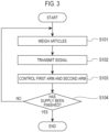
FIG. 3 is a flowchart for describing an exemplary operation of the combination weighing system according to the first embodiment; -
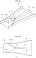
FIGS. 4A and 4B are explanatory views for an exemplary supply apparatus according toModification 1; -
FIG. 5 is an explanatory view for an exemplary supply apparatus according to Modification 2; and -
FIGS. 6A and 6B are explanatory views for an exemplary supply apparatus according to Modification 3. - Hereinafter, the present embodiment will be described in detail with reference to the attached drawings. In the following description of the drawings, the same or similar parts are denoted by the same or similar reference symbols. However, note that the drawings are schematic, and ratios of dimensions are different from actual ones. Therefore, specific dimensions and the like are determined in consideration of the following description. Moreover, there may be portions where dimensional relationships or proportions are different among the drawings. In this specification and the drawings, elements having substantially the same function and configuration are denoted by the same reference numerals to omit redundant description, and elements not directly related to the present invention are omitted.
- A combination weighing system including
weighing mechanisms supply apparatus 10 according to a first embodiment of the present invention will be described below with reference toFIGS. 1 to 3 . - As illustrated in
FIG. 1 , thesupply apparatus 10 according to the present embodiment supplies articles onto two independent distribution tables 2A and 2B that the two adjacentcombination weighing mechanisms - As illustrated in
FIGS. 1 and2 , thesupply apparatus 10 according to the present embodiment includes aconveyer 100, ablocker 13, and acontroller 20. - As illustrated in
FIGS. 1 and2 , theconveyer 100 includes amain conveyance path 11, afirst conveyance path 12A, and asecond conveyance path 12B. - As illustrated in
FIG. 2 , themain conveyance path 11 extends in a direction D1 orthogonal to a straight line L1 connecting therespective centers centers centers FIG. 2 . For example, the distribution tables 2A and 2B are each a member that conveys articles supplied by vibrations from a vibrator, circumferentially and outward. In this case, a composition of vibrations causes articles to be conveyed in a spiral on each of the distribution tables 2A and 2B. - The
first conveyance path 12A is connected continuously to themain conveyance path 11 and supplies articles to the distribution table 2A that is one of the two distribution tables 2A and 2B. Meanwhile, thesecond conveyance path 12B supplies articles to the distribution table 2B that is the other of the two distribution tables 2A and 2B. - As illustrated in
FIG. 2 , theblocker 13 is disposed at afork 12 between themain conveyance path 11, thefirst conveyance path 12A, and thesecond conveyance path 12B. - The
blocker 13 makes a switch between a first state where supply of articles from themain conveyance path 11 to thefirst conveyance path 12A is blocked and a second state where supply of articles from themain conveyance path 11 to thesecond conveyance path 12B is blocked. - As illustrated in
FIG. 2 , in thesupply apparatus 10 according to the present embodiment, apartition 14 may be provided at the center of thefork 12. - As illustrated in
FIGS. 1 and2 , theblocker 13 may include afirst blocker 13A and asecond blocker 13B. Thefirst blocker 13A blocks supply of articles from themain conveyance path 11 to thefirst conveyance path 12A. Meanwhile, thesecond blocker 13B blocks supply of articles from themain conveyance path 11 to thesecond conveyance path 12B. - Specifically, as illustrated in
FIG. 2 , thefirst blocker 13A may be achieved with a first arm extending from aside wall 15A of thesupply apparatus 10. In such a case, in the first state, the leading end 13AT of the first arm is in contact with thepartition 14 due to turning of the first arm (first blocker) 13A around a first axis 13AX, so that supply of articles from themain conveyance path 11 to thefirst conveyance path 12A can be blocked. - As illustrated in
FIG. 2 , thesecond blocker 13B may be achieved with a second arm extending from anotherside wall 15B of thesupply apparatus 10. In such a case, in the second state, the leading end 13BT of the second arm is in contact with thepartition 14 due to turning of the second arm (second blocker) 13B around a second axis 13BX, so that supply of articles from themain conveyance path 11 to thesecond conveyance path 12B can be blocked. - Based on the respective conditions of supply of articles to the two
combination weighing mechanisms controller 20 transitions theblocker 13 into at least either the first state or the second state to switch the route of conveyance of articles. - Note that, as illustrated in
FIG. 2 , theconveyer 100 may have a conveyance face of which the width in a direction D2 along the straight line L1 increases downstream. According to such a configuration, articles conveyed from the upstream side can be inhibited from being stuck in the neighborhood between themain conveyance path 11 and the first conveyance path 11A or the second conveyance path 11B, leading to smooth conveyance of articles. - In the
supply apparatus 10 according to the present embodiment, theconveyer 100 and theside walls - According to such a configuration, articles are hardly caught among the
conveyer 100, theside walls first arm 13A, and thesecond arm 13B, so that articles can be distributed accurately from themain conveyance path 11 to thefirst conveyance path 12A or thesecond conveyance path 12B. - Furthermore, in the
supply apparatus 10 according to the present embodiment, as illustrated inFIGS. 1 and2 , theside walls first arm 13A and thesecond arm 13B extend, through the through holes 15AH and 15BH, outward from theside walls side walls blocker 13 is simple in configuration, and articles being conveyed on themain conveyance path 11 can be inhibited from being contaminated with foreign matter. - An exemplary operation of the combination weighing system according to the present embodiment will be described below with reference to
FIG. 3 . - As illustrated in
FIG. 3 , in step S101, a weight detector (not illustrated) provided below the distribution table 2A detects the weight of articles supplied from thesupply apparatus 10 to the distribution table 2A, and a weight detector (not illustrated) provided below the distribution table 2B detects the weight of articles supplied from thesupply apparatus 10 to the distribution table 2B. - In step S102, each weight detector transmits, to the
controller 20, the detected weight of articles. - In step S103, based on the respective conditions of supply of articles to the two
combination weighing mechanisms controller 20 transitions theblocker 13 into at least either the first state or the second state to switch the route of conveyance of articles. - For example, in a case where a signal received in the first state indicates that the weight of articles is larger than a predetermined threshold, the
controller 20 controls thefirst conveyance path 12A and thesecond conveyance path 12B such that theblocker 13 is brought into the second state to block the supply of articles from themain conveyance path 11 to thesecond conveyance path 12B and to supply articles from themain conveyance path 11 to thefirst conveyance path 12A. - On the other hand, in a case where a signal received in the second state indicates that the weight of articles is larger than a predetermined threshold, the
controller 20 controls thefirst conveyance path 12A and thesecond conveyance path 12B such that theblocker 13 is brought into the first state to block the supply of articles from themain conveyance path 11 to thefirst conveyance path 12A and to supply articles from themain conveyance path 11 to thesecond conveyance path 12B. - According to the present embodiment, with a low installation height due to no intricate mechanism between the
supply apparatus 10 and the weighingmechanisms -
Modification 1 of the present invention will be described below with a focus on the difference from the first embodiment. - As illustrated in
FIGS. 4A and 4B , asupply apparatus 10 according toModification 1 may include ablocker 13 achieved with asingle arm 13C connected to theleading end 14T on the upstream side of apartition 14. - In such a case, in the first state, the leading end of the
arm 13C is in contact with aside wall 15A due to turning of thearm 13C around theleading end 14T, so that supply of articles from amain conveyance path 11 to afirst conveyance path 12A can be blocked. - On the other hand, in the second state, the leading end of the
arm 13C is in contact with anotherside wall 15B due to turning of thearm 13C around theleading end 14T, so that supply of articles from themain conveyance path 11 to asecond conveyance path 12B can be blocked. - Modification 2 of the present invention will be described below with a focus on the difference from the first embodiment.
- As illustrated in
FIG. 5 , asupply apparatus 10 according to Modification 2 may include atabular member 21A as afirst blocker 13A and atabular member 21B as asecond blocker 13B. - The
tabular member 21A blocks supply of articles from amain conveyance path 11 to afirst conveyance path 12A. Meanwhile, thetabular member 21B blocks supply of articles from themain conveyance path 11 to asecond conveyance path 12B. - Specifically, as illustrated in
FIG. 5 , in the first state, thetabular member 21A protrudes from the conveyance face of aconveyer 100 and thetabular member 21B is retracted through the conveyance face of theconveyer 100, so that supply of articles from themain conveyance path 11 to thefirst conveyance path 12A can be blocked. - As illustrated in
FIG. 5 , in the second state, thetabular member 21B protrudes from the conveyance face of theconveyer 100 and thetabular member 21A is retracted through the conveyance face of theconveyer 100, so that supply of articles from themain conveyance path 11 to thesecond conveyance path 12B can be blocked. - Modification 3 of the present invention will be described below with a focus on the difference from the first embodiment.
- As illustrated in
FIG. 6A , asupply apparatus 10 according to Modification 3 includes alower end wall 10T at its end on the downstream side such that no articles are supplied from the end on the downstream side to distribution tables 2A and 2B. - As illustrated in
FIG. 6A , thesupply apparatus 10 according to Modification 3 has a conveyance face provided with a throughhole 10H near thelower end wall 10T. - As illustrated in
FIG. 6B , atabular member 31A may be provided as afirst blocker 13A, and atabular member 31B may be provided as asecond blocker 13B. - The
tabular member 31A blocks supply of articles from amain conveyance path 11 to afirst conveyance path 12A. Meanwhile, thetabular member 31B blocks supply of articles from themain conveyance path 11 to asecond conveyance path 12B. - Specifically, as illustrated in
FIG. 6B , in the first state, thetabular member 31A covers part of the throughhole 10H and thetabular member 31B is located upstream due to its movement, so that supply of articles from themain conveyance path 11 to thefirst conveyance path 12A can be blocked. In such a case, articles are supplied to a distribution table 2B through part of the throughhole 10H, in which the part is exposed due to the movement of thetabular member 31B. - On the other hand, as illustrated in
FIG. 6B , in the second state, thetabular member 31B covers part of the throughhole 10H and thetabular member 31A is located upstream due to its movement, so that supply of articles from themain conveyance path 11 to thesecond conveyance path 12B can be blocked. In such a case, articles are supplied to a distribution table 2A through part of the throughhole 10H, in which the part is exposed due to the movement of thetabular member 31A. - Although the present invention is explained in detail using the above-mentioned embodiments, it will be apparent to those skilled in the art that the present invention is not limited to the embodiments described herein. The present invention can be implemented as modifications and changes without departing from the spirit and scope of the present invention defined by the description of the claims. Accordingly, the description of the present specification is for the purpose of illustration and is not intended to limit the present invention in any way.
-
- 1A, 1B
- Combination weighing mechanism
- 2A, 2B
- Distribution table
- 3A, 3B
- Center of the distribution table
- 10
- Supply apparatus
- 11
- Main conveyance path
- 12
- Fork
- 12A
- First conveyance path
- 12B
- Second conveyance path
- 13
- Blocker
- 13A
- First blocker
- 13AX
- First axis
- 13B
- Second blocker
- 13BX
- Second axis
- 14
- Partition
- 15A, 15B
- Side wall
- 15AH, 15BH
- Through hole
- 20
- Controller
- 21A, 21B, 31A, 31B
- Tabular member
- 100
- Conveyer
Claims (5)
- A supply apparatus for supplying articles onto two independent distribution tables that each of two adjacent combination weighing mechanisms includes, the supply apparatus comprising:a conveyer including:a main conveyance path extending in a direction orthogonal to a straight line connecting respective centers of the two independent distribution tables;a first conveyance path connected continuously to the main conveyance path, the first conveyance path allowing the articles to be supplied to one of the two independent distribution tables; anda second conveyance path allowing the articles to be supplied to another of the two independent distribution tables;a blocker disposed at a fork between the main conveyance path, the first conveyance path, and the second conveyance path, the blocker making a switch between a first state where supply of the articles from the main conveyance path to the first conveyance path is blocked and a second state where supply of the articles from the main conveyance path to the second conveyance path is blocked; anda controller that transitions, based on respective conditions of supply of the articles to the two adjacent combination weighing mechanisms, the blocker into at least either the first state or the second state to switch a route of conveyance of the articles.
- The supply apparatus according to claim 1, wherein the blocker includes:a first blocker that blocks the supply of the articles from the main conveyance path to the first conveyance path; anda second blocker that blocks the supply of the articles from the main conveyance path to the second conveyance path,a partition is provided at a center of the fork,the first blocker includes a first arm extending from a side wall of the supply apparatus,a leading end of the first arm comes in contact with the partition due to turning of the first arm around a first axis such that the supply of the articles from the main conveyance path to the first conveyance path is blocked,the second blocker includes a second arm extending from another side wall of the supply apparatus, anda leading end of the second arm comes in contact with the partition due to turning of the second arm around a second axis such that the supply of the articles from the main conveyance path to the second conveyance path is blocked.
- The supply apparatus according to claim 1 or 2, wherein
the conveyer has a conveyance face of which a width in a direction along the straight line increases downstream. - The supply apparatus according to claim 2 or 3, whereinthe conveyer, the side wall, and the another side wall are formed of metal, andthe first arm and the second arm are formed of resin.
- The supply apparatus according to any of claims 2 to 4, whereinthe side wall and the another side wall have respective through holes,the first arm and the second arm extend outward from the side wall and the another side wall through the respective through holes, andthe first axis and the second axis are located outside the side wall and the another side wall, respectively.
Applications Claiming Priority (1)
| Application Number | Priority Date | Filing Date | Title |
|---|---|---|---|
| JP2023021820A JP2024115913A (en) | 2023-02-15 | 2023-02-15 | Feeding device |
Publications (1)
| Publication Number | Publication Date |
|---|---|
| EP4417547A1 true EP4417547A1 (en) | 2024-08-21 |
Family
ID=89715723
Family Applications (1)
| Application Number | Title | Priority Date | Filing Date |
|---|---|---|---|
| EP24153560.8A Pending EP4417547A1 (en) | 2023-02-15 | 2024-01-23 | Supply apparatus |
Country Status (4)
| Country | Link |
|---|---|
| US (1) | US12600578B2 (en) |
| EP (1) | EP4417547A1 (en) |
| JP (1) | JP2024115913A (en) |
| CN (1) | CN118494896A (en) |
Citations (9)
| Publication number | Priority date | Publication date | Assignee | Title |
|---|---|---|---|---|
| DE4406561C1 (en) * | 1994-03-01 | 1995-09-07 | Florian Hager | Switch-over frame for sorting fruit and vegetables |
| JPH07328552A (en) * | 1994-06-14 | 1995-12-19 | Daido Steel Co Ltd | Apparatus for judging metal molded article |
| WO2001027568A1 (en) * | 1999-10-13 | 2001-04-19 | Recot, Inc. | Stopper gate for product conveyor |
| US20070108016A1 (en) * | 2005-11-04 | 2007-05-17 | Fmc Technologies, Inc. | Gateless modular conveyor distribution system |
| JP3209972U (en) | 2016-12-14 | 2017-04-20 | 株式会社イシダ | Vibrating conveyor and combination weighing device equipped with it |
| US10196212B1 (en) * | 2017-09-07 | 2019-02-05 | Sejong Pharmatech Co., Ltd. | Tablet discharge chute |
| CN210884128U (en) * | 2019-10-11 | 2020-06-30 | 匹帅机械科技(上海)有限公司 | Commodity circulation cross band letter sorting line letter sorting bin mouth buffer |
| CN112938440A (en) * | 2021-01-28 | 2021-06-11 | 铜陵松宝智能装备股份有限公司 | Bobbin distribution finishing equipment and method |
| US20220034030A1 (en) * | 2020-07-30 | 2022-02-03 | Seiko Epson Corporation | Raw material supply device |
Family Cites Families (9)
| Publication number | Priority date | Publication date | Assignee | Title |
|---|---|---|---|---|
| US3543916A (en) * | 1968-09-13 | 1970-12-01 | Westinghouse Air Brake Co | Flow diverting shaker conveyor trough |
| US4678046A (en) * | 1986-01-31 | 1987-07-07 | Package Machinery Company | Combination weighing apparatus for two combined products |
| US5753867A (en) * | 1995-02-02 | 1998-05-19 | Ishida Co., Ltd., | Combinational weighing apparatus |
| US20030127302A1 (en) * | 2001-01-31 | 2003-07-10 | Brewer Marvin Vincent | Regulatory gate system for product drop off of vibratory conveyors |
| AU2008221530B2 (en) * | 2007-11-26 | 2010-07-01 | Tna Australia Pty Limited | A scale for a packaging machine |
| EP2273242B1 (en) * | 2008-04-17 | 2019-12-04 | Ishida Co., Ltd. | Combination measuring device |
| ITRM20130107A1 (en) * | 2012-03-19 | 2013-09-20 | Tna Australia Pty Ltd | CONVEYOR GROUP. |
| JP6255286B2 (en) * | 2014-03-18 | 2017-12-27 | 株式会社イシダ | Distributed supply device and combination weighing device |
| JP6586159B2 (en) * | 2015-03-06 | 2019-10-02 | 株式会社イシダ | Mix weighing device |
-
2023
- 2023-02-15 JP JP2023021820A patent/JP2024115913A/en active Pending
-
2024
- 2024-01-23 EP EP24153560.8A patent/EP4417547A1/en active Pending
- 2024-01-29 US US18/426,284 patent/US12600578B2/en active Active
- 2024-02-05 CN CN202410167520.5A patent/CN118494896A/en active Pending
Patent Citations (9)
| Publication number | Priority date | Publication date | Assignee | Title |
|---|---|---|---|---|
| DE4406561C1 (en) * | 1994-03-01 | 1995-09-07 | Florian Hager | Switch-over frame for sorting fruit and vegetables |
| JPH07328552A (en) * | 1994-06-14 | 1995-12-19 | Daido Steel Co Ltd | Apparatus for judging metal molded article |
| WO2001027568A1 (en) * | 1999-10-13 | 2001-04-19 | Recot, Inc. | Stopper gate for product conveyor |
| US20070108016A1 (en) * | 2005-11-04 | 2007-05-17 | Fmc Technologies, Inc. | Gateless modular conveyor distribution system |
| JP3209972U (en) | 2016-12-14 | 2017-04-20 | 株式会社イシダ | Vibrating conveyor and combination weighing device equipped with it |
| US10196212B1 (en) * | 2017-09-07 | 2019-02-05 | Sejong Pharmatech Co., Ltd. | Tablet discharge chute |
| CN210884128U (en) * | 2019-10-11 | 2020-06-30 | 匹帅机械科技(上海)有限公司 | Commodity circulation cross band letter sorting line letter sorting bin mouth buffer |
| US20220034030A1 (en) * | 2020-07-30 | 2022-02-03 | Seiko Epson Corporation | Raw material supply device |
| CN112938440A (en) * | 2021-01-28 | 2021-06-11 | 铜陵松宝智能装备股份有限公司 | Bobbin distribution finishing equipment and method |
Also Published As
| Publication number | Publication date |
|---|---|
| CN118494896A (en) | 2024-08-16 |
| US20240270507A1 (en) | 2024-08-15 |
| US12600578B2 (en) | 2026-04-14 |
| JP2024115913A (en) | 2024-08-27 |
Similar Documents
| Publication | Publication Date | Title |
|---|---|---|
| US10265732B2 (en) | High-speed, dual-sided shoe sorter with offset induct | |
| EP0938440B1 (en) | Pressureless multi-lane dividing apparatus | |
| EP1843307A1 (en) | Transportation system and transportation method | |
| EP3514825A1 (en) | Wafer sorting apparatus | |
| US12600578B2 (en) | Supply apparatus | |
| US10410895B2 (en) | Conveyance control device and conveyance control system | |
| JP5655200B2 (en) | Article conveying device | |
| GB1594810A (en) | Apparatus for guiding objects and a method of operating the apparatus | |
| JP2024012942A (en) | Goods conveyance equipment | |
| CN117446391B (en) | A system for flexible handling of parts boxes | |
| JPH0423727A (en) | Conveyance device | |
| EP2431339B1 (en) | Glass sheet cutting method and system | |
| KR890011719A (en) | Automatic machine for coil winding and winding finishing | |
| CN113120505A (en) | Conveying device and conveying method | |
| JP2011079081A (en) | Carrying line | |
| US20060018737A1 (en) | Automated material handling system | |
| US20040042878A1 (en) | Transfer method | |
| EP4417945B1 (en) | Combination weighing apparatus | |
| JP2002167028A (en) | Distributing apparatus and article distributing method used in article processing system | |
| JP4447483B2 (en) | Transport system | |
| JP2015146101A (en) | Production system | |
| JP2011020790A (en) | Sorting device and sorting device control method | |
| KR20010054697A (en) | System for transporting a semiconductor device | |
| JP2007137569A (en) | Merge control device and merge control method in conveyor system | |
| JP2828436B2 (en) | Method of setting transfer route of semiconductor manufacturing line |
Legal Events
| Date | Code | Title | Description |
|---|---|---|---|
| PUAI | Public reference made under article 153(3) epc to a published international application that has entered the european phase |
Free format text: ORIGINAL CODE: 0009012 |
|
| STAA | Information on the status of an ep patent application or granted ep patent |
Free format text: STATUS: REQUEST FOR EXAMINATION WAS MADE |
|
| 17P | Request for examination filed |
Effective date: 20240123 |
|
| AK | Designated contracting states |
Kind code of ref document: A1 Designated state(s): AL AT BE BG CH CY CZ DE DK EE ES FI FR GB GR HR HU IE IS IT LI LT LU LV MC ME MK MT NL NO PL PT RO RS SE SI SK SM TR |