EP4417499A1 - Straddle vehicle - Google Patents
Straddle vehicle Download PDFInfo
- Publication number
- EP4417499A1 EP4417499A1 EP24158621.3A EP24158621A EP4417499A1 EP 4417499 A1 EP4417499 A1 EP 4417499A1 EP 24158621 A EP24158621 A EP 24158621A EP 4417499 A1 EP4417499 A1 EP 4417499A1
- Authority
- EP
- European Patent Office
- Prior art keywords
- tank
- tanks
- wheel
- vehicle
- combustion engine
- Prior art date
- Legal status (The legal status is an assumption and is not a legal conclusion. Google has not performed a legal analysis and makes no representation as to the accuracy of the status listed.)
- Pending
Links
Images

Classifications
-
- B—PERFORMING OPERATIONS; TRANSPORTING
- B62—LAND VEHICLES FOR TRAVELLING OTHERWISE THAN ON RAILS
- B62M—RIDER PROPULSION OF WHEELED VEHICLES OR SLEDGES; POWERED PROPULSION OF SLEDGES OR SINGLE-TRACK CYCLES; TRANSMISSIONS SPECIALLY ADAPTED FOR SUCH VEHICLES
- B62M7/00—Motorcycles characterised by position of motor or engine
- B62M7/02—Motorcycles characterised by position of motor or engine with engine between front and rear wheels
- B62M7/04—Motorcycles characterised by position of motor or engine with engine between front and rear wheels below the frame
-
- B—PERFORMING OPERATIONS; TRANSPORTING
- B62—LAND VEHICLES FOR TRAVELLING OTHERWISE THAN ON RAILS
- B62J—CYCLE SADDLES OR SEATS; AUXILIARY DEVICES OR ACCESSORIES SPECIALLY ADAPTED TO CYCLES AND NOT OTHERWISE PROVIDED FOR, e.g. ARTICLE CARRIERS OR CYCLE PROTECTORS
- B62J35/00—Fuel tanks specially adapted for motorcycles or engine-assisted cycles; Arrangements thereof
-
- B—PERFORMING OPERATIONS; TRANSPORTING
- B62—LAND VEHICLES FOR TRAVELLING OTHERWISE THAN ON RAILS
- B62K—CYCLES; CYCLE FRAMES; CYCLE STEERING DEVICES; RIDER-OPERATED TERMINAL CONTROLS SPECIALLY ADAPTED FOR CYCLES; CYCLE AXLE SUSPENSIONS; CYCLE SIDECARS, FORECARS, OR THE LIKE
- B62K11/00—Motorcycles, engine-assisted cycles or motor scooters with one or two wheels
- B62K11/02—Frames
- B62K11/04—Frames characterised by the engine being between front and rear wheels
-
- B—PERFORMING OPERATIONS; TRANSPORTING
- B62—LAND VEHICLES FOR TRAVELLING OTHERWISE THAN ON RAILS
- B62K—CYCLES; CYCLE FRAMES; CYCLE STEERING DEVICES; RIDER-OPERATED TERMINAL CONTROLS SPECIALLY ADAPTED FOR CYCLES; CYCLE AXLE SUSPENSIONS; CYCLE SIDECARS, FORECARS, OR THE LIKE
- B62K5/00—Cycles with handlebars, equipped with three or more main road wheels
- B62K5/02—Tricycles
- B62K5/027—Motorcycles with three wheels
-
- B—PERFORMING OPERATIONS; TRANSPORTING
- B60—VEHICLES IN GENERAL
- B60K—ARRANGEMENT OR MOUNTING OF PROPULSION UNITS OR OF TRANSMISSIONS IN VEHICLES; ARRANGEMENT OR MOUNTING OF PLURAL DIVERSE PRIME-MOVERS IN VEHICLES; AUXILIARY DRIVES FOR VEHICLES; INSTRUMENTATION OR DASHBOARDS FOR VEHICLES; ARRANGEMENTS IN CONNECTION WITH COOLING, AIR INTAKE, GAS EXHAUST OR FUEL SUPPLY OF PROPULSION UNITS IN VEHICLES
- B60K13/00—Arrangement in connection with combustion air intake or gas exhaust of propulsion units
-
- B—PERFORMING OPERATIONS; TRANSPORTING
- B60—VEHICLES IN GENERAL
- B60K—ARRANGEMENT OR MOUNTING OF PROPULSION UNITS OR OF TRANSMISSIONS IN VEHICLES; ARRANGEMENT OR MOUNTING OF PLURAL DIVERSE PRIME-MOVERS IN VEHICLES; AUXILIARY DRIVES FOR VEHICLES; INSTRUMENTATION OR DASHBOARDS FOR VEHICLES; ARRANGEMENTS IN CONNECTION WITH COOLING, AIR INTAKE, GAS EXHAUST OR FUEL SUPPLY OF PROPULSION UNITS IN VEHICLES
- B60K13/00—Arrangement in connection with combustion air intake or gas exhaust of propulsion units
- B60K13/02—Arrangement in connection with combustion air intake or gas exhaust of propulsion units concerning intake
-
- B—PERFORMING OPERATIONS; TRANSPORTING
- B60—VEHICLES IN GENERAL
- B60K—ARRANGEMENT OR MOUNTING OF PROPULSION UNITS OR OF TRANSMISSIONS IN VEHICLES; ARRANGEMENT OR MOUNTING OF PLURAL DIVERSE PRIME-MOVERS IN VEHICLES; AUXILIARY DRIVES FOR VEHICLES; INSTRUMENTATION OR DASHBOARDS FOR VEHICLES; ARRANGEMENTS IN CONNECTION WITH COOLING, AIR INTAKE, GAS EXHAUST OR FUEL SUPPLY OF PROPULSION UNITS IN VEHICLES
- B60K13/00—Arrangement in connection with combustion air intake or gas exhaust of propulsion units
- B60K13/04—Arrangement in connection with combustion air intake or gas exhaust of propulsion units concerning exhaust
-
- B—PERFORMING OPERATIONS; TRANSPORTING
- B60—VEHICLES IN GENERAL
- B60K—ARRANGEMENT OR MOUNTING OF PROPULSION UNITS OR OF TRANSMISSIONS IN VEHICLES; ARRANGEMENT OR MOUNTING OF PLURAL DIVERSE PRIME-MOVERS IN VEHICLES; AUXILIARY DRIVES FOR VEHICLES; INSTRUMENTATION OR DASHBOARDS FOR VEHICLES; ARRANGEMENTS IN CONNECTION WITH COOLING, AIR INTAKE, GAS EXHAUST OR FUEL SUPPLY OF PROPULSION UNITS IN VEHICLES
- B60K15/00—Arrangement in connection with fuel supply of combustion engines or other fuel consuming energy converters, e.g. fuel cells; Mounting or construction of fuel tanks
-
- B—PERFORMING OPERATIONS; TRANSPORTING
- B60—VEHICLES IN GENERAL
- B60K—ARRANGEMENT OR MOUNTING OF PROPULSION UNITS OR OF TRANSMISSIONS IN VEHICLES; ARRANGEMENT OR MOUNTING OF PLURAL DIVERSE PRIME-MOVERS IN VEHICLES; AUXILIARY DRIVES FOR VEHICLES; INSTRUMENTATION OR DASHBOARDS FOR VEHICLES; ARRANGEMENTS IN CONNECTION WITH COOLING, AIR INTAKE, GAS EXHAUST OR FUEL SUPPLY OF PROPULSION UNITS IN VEHICLES
- B60K15/00—Arrangement in connection with fuel supply of combustion engines or other fuel consuming energy converters, e.g. fuel cells; Mounting or construction of fuel tanks
- B60K15/01—Arrangement of fuel conduits
-
- B—PERFORMING OPERATIONS; TRANSPORTING
- B60—VEHICLES IN GENERAL
- B60K—ARRANGEMENT OR MOUNTING OF PROPULSION UNITS OR OF TRANSMISSIONS IN VEHICLES; ARRANGEMENT OR MOUNTING OF PLURAL DIVERSE PRIME-MOVERS IN VEHICLES; AUXILIARY DRIVES FOR VEHICLES; INSTRUMENTATION OR DASHBOARDS FOR VEHICLES; ARRANGEMENTS IN CONNECTION WITH COOLING, AIR INTAKE, GAS EXHAUST OR FUEL SUPPLY OF PROPULSION UNITS IN VEHICLES
- B60K15/00—Arrangement in connection with fuel supply of combustion engines or other fuel consuming energy converters, e.g. fuel cells; Mounting or construction of fuel tanks
- B60K15/01—Arrangement of fuel conduits
- B60K15/013—Arrangement of fuel conduits of gas conduits
-
- B—PERFORMING OPERATIONS; TRANSPORTING
- B60—VEHICLES IN GENERAL
- B60K—ARRANGEMENT OR MOUNTING OF PROPULSION UNITS OR OF TRANSMISSIONS IN VEHICLES; ARRANGEMENT OR MOUNTING OF PLURAL DIVERSE PRIME-MOVERS IN VEHICLES; AUXILIARY DRIVES FOR VEHICLES; INSTRUMENTATION OR DASHBOARDS FOR VEHICLES; ARRANGEMENTS IN CONNECTION WITH COOLING, AIR INTAKE, GAS EXHAUST OR FUEL SUPPLY OF PROPULSION UNITS IN VEHICLES
- B60K15/00—Arrangement in connection with fuel supply of combustion engines or other fuel consuming energy converters, e.g. fuel cells; Mounting or construction of fuel tanks
- B60K15/03—Fuel tanks
-
- B—PERFORMING OPERATIONS; TRANSPORTING
- B60—VEHICLES IN GENERAL
- B60K—ARRANGEMENT OR MOUNTING OF PROPULSION UNITS OR OF TRANSMISSIONS IN VEHICLES; ARRANGEMENT OR MOUNTING OF PLURAL DIVERSE PRIME-MOVERS IN VEHICLES; AUXILIARY DRIVES FOR VEHICLES; INSTRUMENTATION OR DASHBOARDS FOR VEHICLES; ARRANGEMENTS IN CONNECTION WITH COOLING, AIR INTAKE, GAS EXHAUST OR FUEL SUPPLY OF PROPULSION UNITS IN VEHICLES
- B60K15/00—Arrangement in connection with fuel supply of combustion engines or other fuel consuming energy converters, e.g. fuel cells; Mounting or construction of fuel tanks
- B60K15/03—Fuel tanks
- B60K15/03006—Gas tanks
-
- B—PERFORMING OPERATIONS; TRANSPORTING
- B60—VEHICLES IN GENERAL
- B60K—ARRANGEMENT OR MOUNTING OF PROPULSION UNITS OR OF TRANSMISSIONS IN VEHICLES; ARRANGEMENT OR MOUNTING OF PLURAL DIVERSE PRIME-MOVERS IN VEHICLES; AUXILIARY DRIVES FOR VEHICLES; INSTRUMENTATION OR DASHBOARDS FOR VEHICLES; ARRANGEMENTS IN CONNECTION WITH COOLING, AIR INTAKE, GAS EXHAUST OR FUEL SUPPLY OF PROPULSION UNITS IN VEHICLES
- B60K15/00—Arrangement in connection with fuel supply of combustion engines or other fuel consuming energy converters, e.g. fuel cells; Mounting or construction of fuel tanks
- B60K15/03—Fuel tanks
- B60K2015/03032—Manufacturing of fuel tanks
-
- B—PERFORMING OPERATIONS; TRANSPORTING
- B60—VEHICLES IN GENERAL
- B60K—ARRANGEMENT OR MOUNTING OF PROPULSION UNITS OR OF TRANSMISSIONS IN VEHICLES; ARRANGEMENT OR MOUNTING OF PLURAL DIVERSE PRIME-MOVERS IN VEHICLES; AUXILIARY DRIVES FOR VEHICLES; INSTRUMENTATION OR DASHBOARDS FOR VEHICLES; ARRANGEMENTS IN CONNECTION WITH COOLING, AIR INTAKE, GAS EXHAUST OR FUEL SUPPLY OF PROPULSION UNITS IN VEHICLES
- B60K15/00—Arrangement in connection with fuel supply of combustion engines or other fuel consuming energy converters, e.g. fuel cells; Mounting or construction of fuel tanks
- B60K15/03—Fuel tanks
- B60K2015/03032—Manufacturing of fuel tanks
- B60K2015/03059—Fuel tanks with double shells or more
-
- B—PERFORMING OPERATIONS; TRANSPORTING
- B60—VEHICLES IN GENERAL
- B60K—ARRANGEMENT OR MOUNTING OF PROPULSION UNITS OR OF TRANSMISSIONS IN VEHICLES; ARRANGEMENT OR MOUNTING OF PLURAL DIVERSE PRIME-MOVERS IN VEHICLES; AUXILIARY DRIVES FOR VEHICLES; INSTRUMENTATION OR DASHBOARDS FOR VEHICLES; ARRANGEMENTS IN CONNECTION WITH COOLING, AIR INTAKE, GAS EXHAUST OR FUEL SUPPLY OF PROPULSION UNITS IN VEHICLES
- B60K15/00—Arrangement in connection with fuel supply of combustion engines or other fuel consuming energy converters, e.g. fuel cells; Mounting or construction of fuel tanks
- B60K15/03—Fuel tanks
- B60K2015/03118—Multiple tanks, i.e. two or more separate tanks
-
- B—PERFORMING OPERATIONS; TRANSPORTING
- B60—VEHICLES IN GENERAL
- B60K—ARRANGEMENT OR MOUNTING OF PROPULSION UNITS OR OF TRANSMISSIONS IN VEHICLES; ARRANGEMENT OR MOUNTING OF PLURAL DIVERSE PRIME-MOVERS IN VEHICLES; AUXILIARY DRIVES FOR VEHICLES; INSTRUMENTATION OR DASHBOARDS FOR VEHICLES; ARRANGEMENTS IN CONNECTION WITH COOLING, AIR INTAKE, GAS EXHAUST OR FUEL SUPPLY OF PROPULSION UNITS IN VEHICLES
- B60K15/00—Arrangement in connection with fuel supply of combustion engines or other fuel consuming energy converters, e.g. fuel cells; Mounting or construction of fuel tanks
- B60K15/03—Fuel tanks
- B60K2015/03118—Multiple tanks, i.e. two or more separate tanks
- B60K2015/03157—Multiple tanks, i.e. two or more separate tanks for supply different types of fuel to the motor
-
- B—PERFORMING OPERATIONS; TRANSPORTING
- B60—VEHICLES IN GENERAL
- B60K—ARRANGEMENT OR MOUNTING OF PROPULSION UNITS OR OF TRANSMISSIONS IN VEHICLES; ARRANGEMENT OR MOUNTING OF PLURAL DIVERSE PRIME-MOVERS IN VEHICLES; AUXILIARY DRIVES FOR VEHICLES; INSTRUMENTATION OR DASHBOARDS FOR VEHICLES; ARRANGEMENTS IN CONNECTION WITH COOLING, AIR INTAKE, GAS EXHAUST OR FUEL SUPPLY OF PROPULSION UNITS IN VEHICLES
- B60K15/00—Arrangement in connection with fuel supply of combustion engines or other fuel consuming energy converters, e.g. fuel cells; Mounting or construction of fuel tanks
- B60K15/03—Fuel tanks
- B60K2015/03164—Modular concepts for fuel tanks
-
- B—PERFORMING OPERATIONS; TRANSPORTING
- B62—LAND VEHICLES FOR TRAVELLING OTHERWISE THAN ON RAILS
- B62J—CYCLE SADDLES OR SEATS; AUXILIARY DEVICES OR ACCESSORIES SPECIALLY ADAPTED TO CYCLES AND NOT OTHERWISE PROVIDED FOR, e.g. ARTICLE CARRIERS OR CYCLE PROTECTORS
- B62J37/00—Arrangements of fuel supply lines, taps, or the like, on motor cycles or engine-assisted cycles
-
- B—PERFORMING OPERATIONS; TRANSPORTING
- B62—LAND VEHICLES FOR TRAVELLING OTHERWISE THAN ON RAILS
- B62K—CYCLES; CYCLE FRAMES; CYCLE STEERING DEVICES; RIDER-OPERATED TERMINAL CONTROLS SPECIALLY ADAPTED FOR CYCLES; CYCLE AXLE SUSPENSIONS; CYCLE SIDECARS, FORECARS, OR THE LIKE
- B62K11/00—Motorcycles, engine-assisted cycles or motor scooters with one or two wheels
- B62K11/02—Frames
- B62K11/10—Frames characterised by the engine being over or beside driven rear wheel
-
- B—PERFORMING OPERATIONS; TRANSPORTING
- B62—LAND VEHICLES FOR TRAVELLING OTHERWISE THAN ON RAILS
- B62K—CYCLES; CYCLE FRAMES; CYCLE STEERING DEVICES; RIDER-OPERATED TERMINAL CONTROLS SPECIALLY ADAPTED FOR CYCLES; CYCLE AXLE SUSPENSIONS; CYCLE SIDECARS, FORECARS, OR THE LIKE
- B62K11/00—Motorcycles, engine-assisted cycles or motor scooters with one or two wheels
- B62K11/12—Steering wheel forks characterised by the association therewith of engine
Definitions
- the present application mainly relates to a straddle vehicle including an internal combustion engine that uses gaseous fuel to generate power.
- PTL 1 is International Publication WO2012/066598 .
- PTL 1 discloses an electric two-wheeled vehicle.
- the electric two-wheeled vehicle of PTL 1 includes a battery case in which a battery is housed, and a motor driven by electric energy stored in the battery.
- the battery case which is a heavy object, is located relatively forward in order to suppress wheelies, front wheel floatation, and front wheel slippage.
- line A2 which indicates the midpoint between the center of the front wheels and the center of the rear wheels in the front-rear direction
- the portion of the battery case that occupies more forward than line A2 is larger than the portion of the battery case that occupies more rearward than line A2.
- the electric vehicle of PTL 1 does not include an internal combustion engine that uses gaseous fuel to generate power. Therefore, PTL 1 does not disclose an appropriate layout for a tank filled with gaseous fuel. In addition, depending on the location of the tank, the installation load on the steering wheel may be lower.
- the present application has been made in view of the above circumstances, and its main objective is to locate a tank filled with gaseous fuel in a position where the installation load on the steering wheel is high, for a straddle vehicle including an internal combustion engine that uses gaseous fuel to generate power.
- the straddle vehicle includes a front wheel, a rear wheel, a tank, an internal combustion engine, a seat, and a steering handle.
- the front wheel is a steering wheel.
- the rear wheel is a drive wheel located rearward of the front wheel.
- the tank is filled with gaseous fuel.
- the internal combustion engine generates power using the gaseous fuel filled in the tank.
- a driver sits on the seat. The driver performs a steering operation on the steering handle.
- a center of gravity of the tank is located closer to the steering wheel with respect to a center of gravity of the internal combustion engine.
- the tank filled with gaseous fuel is located at a position where the installation load on the steering wheel is higher.
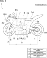
- FIG. 1 is a side view of the first embodiment of the straddle vehicle 1.
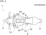
- FIG. 2 is a plan view of the first embodiment of the straddle vehicle 1.
- the left and right directions of the straddle vehicle 1 are defined as the direction viewed from a driver riding in the straddle vehicle 1. Therefore, a front-back direction corresponds to a vehicle length direction, and a left-right direction corresponds to a vehicle width direction. A vertical direction and an upper/lower direction correspond to a height direction.
- the straddle vehicle 1 includes a vehicle body 2, a front wheel 3, and a rear wheel 4. The front wheel 3 and the rear wheel 4 are spaced apart in the vehicle length direction.
- the straddle vehicle 1 is a passenger-type vehicle.
- the straddle vehicle 1 is a type of vehicle in which the driver rides astride.
- the straddle vehicle 1 may be a vehicle for transportation purposes or a leisure vehicle for leisure purposes.
- the vehicle body 2 includes a plurality of frames 2a that serve as the framework of the straddle vehicle 1.
- Various components of the straddle vehicle 1 are mounted to the frames 2a.
- the front wheel 3 is mounted to the frame 2a via a front fork 5.
- the rear wheel 4 is mounted to the frame 2a via swing arm 6.
- the swing arm 6 supports the rear wheel 4 rockingly.
- a first tank 7 and a second tank 8 and an internal combustion engine 9 are mounted to the frame 2a.
- the swing arm 6 and the internal combustion engine 9 are separate and connected via the frame 2a.
- the first tank 7 and the second tank 8 are containers that stores gaseous fuel.
- the gaseous fuel in the first embodiment is hydrogen.
- the gaseous fuel is not limited to hydrogen and may be natural gas, for example.
- the gaseous fuel is filled into the first tank 7 and the second tank 8 at a pressure higher than atmospheric pressure. Therefore, the first tank 7 and the second tank 8 tend to be heavy because the first tank 7 and the second tank 8 are required to be high pressure resistance.
- Two tanks are provided with the straddle vehicle 1. Alternatively, one or more than two tanks may be provided in the straddle vehicle 1.
- the first tank 7 and the second tank 8 are removable.
- the straddle vehicle 1 includes an container 21.
- the container 21 includes space to accommodate the first tank 7 and the second tank 8.
- the container 21 can hold and release the first tank 7 and the second tank 8 that are accommodated in the container 21. For example, when refilling the first tank 7 and the second tank 8 with gaseous fuel, the first tank 7 and the second tank 8 are removed from the container 21.
- the first tank 7 and second tank 8 are surrounded by a mounting 22, a pressure reducing valve 23, and a shut-off valve 24.
- the mounting 22 is provided for the first tank 7 and the second tank 8, respectively.
- Gas supply port is provided at the bottom of each of the first tank 7 and the second tank 8, and each mounting 22 has a mounting port for attaching the gas supply port.
- the pressure reducing valve 23 is located downstream of each the mounting 22 in the gaseous fuel flow direction.
- the pressure reducing valve 23 reduces the pressure of the gaseous fuel supplied from the first tank 7 and the second tank 8.
- one pressure reducing valve 23 is provided, and one pressure reducing valve 23 reduces the pressure of the gaseous fuel in the first tank 7 and the second tank 8.
- the pressure reducing valves 23 may be provided for each of the first tank 7 and the second tank 8.
- the shut-off valve 24 is located downstream of each of the pressure reducing valves 23 in the gaseous fuel flow direction.
- the shut-off valve 24 is switchable between an open state in which the gaseous fuel supplied from the pressure reducing valve 23 flows downstream and a shut-off state in which the gaseous fuel supplied from the pressure reducing valve 23 is shut off.
- the shut-off valve 24 is a solenoid valve, which switches between the open state and the shut-off state by opening and closing the valve in response to an external signal. Normally, the shut-off valve 24 is in the open state, and when an abnormality occurs, the shut-off valve 24 is closed in response to an external signal. The gaseous fuel that passes through the shut-off valve 24 flows toward the internal combustion engine 9.
- the pressure reducing valve 23 and shut-off valve 24 are valves that reduce or shut off the pressure of the gaseous fuel, the pressure reducing valve 23 and shut-off valve 24 correspond to "regulating valves".
- the pressure reducing valve 23 and shut-off valve 24 are not essential configurations and can be omitted.
- An intake structure 11 is a structure that supplies intake air to the internal combustion engine 9. Specifically, the intake structure 11 has an air cleaner box and an intake pipe. The air cleaner box removes dust and other particles contained in the intake air. The intake air purified by the air cleaner box flows through the intake pipe toward the internal combustion engine 9. If the internal combustion engine 9 has multiple cylinders, the intake structure 11 is further provided with an intake manifold.
- the internal combustion engine 9 generates power using gaseous fuel.
- the internal combustion engine 9 includes a cylinder case and a crankcase. A mixture of gaseous fuel and intake air is supplied to the cylinder in the cylinder case. When the mixture in the cylinder is compressed and the mixture is ignited, the piston moves in a linear motion. The linear motion of the piston is converted into rotational motion by a connecting rod and transmitted to a crankshaft. The crankshaft and the transmission gear are accommodated in the crankcase.
- the transmission gear is provided as part of the internal combustion engine 9. Alternatively, the transmission gear may be provided separately from the internal combustion engine 9.
- the power generated in the above manner is transmitted to the rear wheel 4, which is the drive wheel, via a drive chain 10.
- the transmission of drive from the internal combustion engine 9 to the rear wheel 4 is not limited to the drive chain 10, but may also use a belt or shaft.
- the front wheel 3 may be the drive wheel.
- An exhaust structure 12 is a structure that exhausts exhaust air generated by combustion in the internal combustion engine 9.
- the exhaust structure 12 includes an exhaust pipe and a catalyzer.
- the exhaust air generated by the internal combustion engine 9 flows through the exhaust pipe to the catalyzer.
- the catalyzer has an area where a catalyst is arranged to reduce the concentration of nitrogen oxides generated by air combustion. The concentration of nitrogen oxides is reduced when the exhaust air passes through the catalyzer.
- the exhaust air that has passed through the catalyzer is exhausted to the outside. If the internal combustion engine 9 has multiple cylinders, the exhaust structure 12 is further provided with an exhaust manifold.
- the front fork 5 and a steering handle 13 are provided at the front of the vehicle body 2.
- the front forks 5 are arranged in pairs on either side so as to sandwich the front wheel 3 in the front view.
- the steering handle 13 is connected to the upper end of the front fork 5.
- the front forks 5 is rotated by performing a steering operation which is an operation of rotating the steering handle 13 by the driver. This allows the straddle vehicle 1 to turn.
- the straddle vehicle 1 is a lean type vehicle in which the vehicle body 2 is inclined toward the center of the turn with respect to the road surface when turning.
- the straddle vehicle 1 further includes a seat 14 and a step 15.
- the driver sits on the seat 14 and places his/her foot on the step 15 which is bar-shaped arranged on the side of the vehicle body 2.
- the straddle vehicle 1 is a straddle-type.
- the straddle vehicle 1 of the first embodiment is a sports type vehicle.
- the sports type vehicle is a type of vehicle in which the driver puts his/her foot on the bar-shaped step 15 and the position of the step 15 in the vehicle length direction overlaps with the seat 14, so that the driver tends to lean forward.
- the straddle vehicle 1 of the first embodiment has the above-described configuration, and can be modified to above-described another configuration.
- the explanation is not limited to the straddle vehicle 1 of the first embodiment, but also apply to the straddle vehicles 1 of the second to fourth embodiments described below, unless otherwise specified.
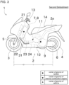
- FIG. 3 is a side view of the straddle vehicle 1 of the second embodiment.
- the straddle vehicle 1 of the second embodiment is a scooter type vehicle.
- the scooter type is a type of vehicle that has a floor plate for placing feet of the driver, and the floor plate is located in front of the seat 14, so that the driver is less likely to lean forward.
- a pair of left and right footrests 31 provided on both sides of the vehicle body 2 correspond to a floor plate. Note that instead of the pair of left and right footrests 31, one floor may be provided.
- the floor extends left and right from a center position in the vehicle width direction, and is a part where the driver's feet or luggage can be placed.
- the straddle vehicle 1 of the second embodiment is a straddle type. Even if a floor is provided instead of the footrest 31, the driver is in a riding posture similar to that of a driver riding in the straddle vehicle 1 of the second embodiment, thus such vehicle is also straddle type. That is, in this description, a scooter type vehicle corresponds to a straddle vehicle.
- the straddle vehicle 1 is a lean type vehicle in which the vehicle body 2 is inclined toward the center of the turn with respect to the road surface when turning.
- the straddle vehicle 1 of the second embodiment is a swing unit type, and the swing arm 6 and the internal combustion engine 9 are integrally configured. In other words, the swing arm 6 is directly attached to the internal combustion engine 9.
- the straddle vehicle 1 of the second embodiment has a belt-type CVT, and the CVT is used for changing gears.
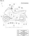
- the straddle vehicle 1 of the third embodiment has the same configuration as the straddle vehicle 1 of the second embodiment, except that the layout of the first tank 7 and the second tank 8 is different, as will be described later.
- FIG. 5 is a side view of the straddle vehicle 1 of the fourth embodiment.
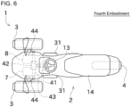
- FIG. 6 is a plan view of the straddle vehicle 1 of the fourth embodiment.
- the straddle vehicle 1 of the first embodiment to the third embodiment is a vehicle that has one front wheel 3 and one rear wheel 4.
- the straddle vehicle 1 of the fourth embodiment is a vehicle that has two front wheels 3 and one rear wheel 4.
- the straddle vehicle 1 may be a vehicle with one front wheel 3 and two rear wheels 4, or may be a vehicle with two front wheels 3 and two rear wheels 4.
- a vehicle with two front wheels 3 refers to a vehicle in which the front wheels 3 are arranged symmetrically on the left and right sides with center position in the vehicle width direction as a line of symmetry. The same applies to vehicles with two rear wheels 4.
- the straddle vehicle 1 of the fourth embodiment has a steering structure different from that of the above embodiments.
- the straddle vehicle 1 of the fourth embodiment includes a steering handle 13 which is a wheel type.
- the straddle vehicle 1 includes a steering shaft 41, a steering gearbox 42, a steering rod 43, and a pair of left and right knuckle arms 44, as a steering structure.
- the steering force applied by the driver to the steering handle 13 is transmitted to the steering gear box 42 via the steering shaft 41.
- the steering gear box 42 amplifies the rotational movement of the steering shaft 41.
- the steering rod 43 reciprocates.
- the knuckle arm 44 fixed to the tip of the steering rod 43 applies force to the front wheel 3 to change the direction of the front wheel 3.
- first tank 7 and the second tank 8 will be collectively referred to as "tanks 7, 8."
- wording "parallel” includes not only a state where two straight lines are strictly parallel, but also a state where two straight lines are substantially parallel, in other words, approximately parallel. The same applies not only to "parallel” but also to wordings such as "perpendicular” or "coincidence” or the like.
- the directions of the tanks 7, 8 will be described. Since the tanks 7, 8 of the above embodiments have a cylindrical shape, the central axis of the cylinder is referred to as the axis of the tanks 7, 8. In addition, when the tanks 7, 8 are not cylindrical, the line passing through the center position of the cross section perpendicular to the longitudinal direction of the tanks 7, 8 corresponds to the axis of the tanks 7, 8. In the first to fourth embodiments, the axis of the first tank 7 and the axis of the second tank 8 are parallel.
- the axes of the tanks 7, 8 are parallel to the height direction, and the tanks 7, 8 are arranged side by side in the vehicle length direction. Thereby, the size of the tanks 7, 8 in the vehicle width direction can be reduced.
- the tanks 7, 8 are arranged side by side in the vehicle length direction, they are arranged so that the entire tanks 7, 8 overlap when viewed in the vehicle length direction. However, it is not necessary that the tanks 7, 8 completely overlap when viewed in the vehicle length direction. The same applies when the tanks 7, 8 are arranged side by side in other directions.
- the axes of the tanks 7, 8 are parallel to the height direction, and the tanks 7, 8 are arranged side by side in the vehicle width direction. Thereby, the size of the tanks 7, 8 in the vehicle length direction can be reduced.
- the axes of the tanks 7, 8 in the second embodiment are parallel to the longitudinal direction of the front fork 5, in other words, the axes are parallel to the steering axis direction. Thereby, the tanks 7, 8 can be arranged by effectively utilizing the shape of the space around the front fork 5.
- the axes of the tanks 7, 8 are preferably parallel to the height direction. Specifically, it is preferable that the angles of the axes of the tanks 7, 8 is within an acute angle range formed by the height direction and the longitudinal direction of the front fork 5.
- Each of the features is particularly effective for motorcycles such as the first to third embodiments, but can also be applied to three wheel or four wheel vehicles such as the fourth embodiment.
- the tanks 7, 8 are removable. Since the axes of the tanks 7, 8 are parallel to the height direction, it is suitable for attaching and detaching the tanks 7, 8. For example, since the tanks 7, 8 can be attached and detached using the space above the container 21, it is easy to attach and detach the tanks 7, 8 even when the space around the straddle vehicle 1 is narrow. The tanks 7, 8 can be attached in the container 21 using their own weight.
- the axes of the tanks 7, 8 are parallel to the vehicle length direction, and the tanks 7, 8 are arranged side by side in the vehicle width direction. Thereby, the size of the tanks 7, 8 in the height direction can be reduced. Since two front wheels 3 are arranged in the straddle vehicle 1 of the fourth embodiment, the requirement to reduce the size in the vehicle width direction is not as strong as in a two wheel vehicle. Therefore, the layout of the tanks 7, 8 of the fourth embodiment is particularly effective for a three-wheeled or four-wheeled vehicle like the fourth embodiment. The layout of the tanks 7, 8 of the fourth embodiment can also be applied to a two wheel vehicle.
- the axes of the tanks 7, 8 are perpendicular to the vehicle width direction. Thereby, the size in the vehicle width direction can be reduced compared to the vehicle in which the axes of the tanks 7, 8 are parallel to the vehicle width direction.
- the direction and alignment of the tanks 7, 8 described above are merely examples, and may be changed as follows.
- the axes of the tanks 7, 8 may be parallel to the vehicle length direction, and the tanks 7, 8 may be arranged side by side in the height direction.
- the axes of the tanks 7, 8 may be parallel to the vehicle width direction, and the tanks 7, 8 may be arranged side by side in the vehicle length direction or height direction.
- the axes of the tanks 7, 8 may not be parallel.
- the axes of the tanks 7, 8 may be arranged in a V-shape when viewed from the front. When three or more tanks are arranged, all the tanks may be arranged along one line, or may be arranged along two lines.
- the tanks 7, 8 are heavy objects.
- the vertical load of the front wheel 3, which is steering wheel is increased. This improves steering performance.
- the center of gravity of the tanks 7, 8 is located forward of the center of gravity of the vehicle.
- the centers of gravity of the tanks 7 and 8 are located forward of the center of gravity of the internal combustion engine 9.
- the rear end of each of the tanks 7, 8 is located further forward than the front end of the internal combustion engine 9.
- the center of gravity of the tanks 7, 8 is located in the front region of the region bisecting the space between the front wheels 3 and the rear wheels 4. In other words, the center of gravity of the tanks 7, 8 is located behind the front wheels 3.
- the center of gravity of the tanks 7, 8 is located forward of the seat 14.
- the rear ends of the tanks 7, 8 are located forward of the front end of the seat 14.
- the range occupied by the front wheel 3 and the range occupied by the tanks 7, 8 overlap in the vehicle length direction.
- the wordings "front” or “forward” can also be reffed as "side where the steering wheel is located".
- the above-mentioned features are individual features, and even if only one of the positional relationships is executed, the effect that the tanks 7, 8 are located near the steering wheel can be achieved. Alternatively, any of the above positional relationships may be combined. Thereby, the effect that the tanks 7, 8 are located near the steering wheel can be further utilized.
- the center of gravity of the tanks 7, 8 is located at the rear of the front fork 5.
- the tanks 7, 8 do not overlap the front fork 5 in the side view of the straddle vehicle.
- the tanks 7, 8 and the front fork 5 may overlap in the side view of the straddle vehicle.
- the center of gravity of the tanks 7, 8 may be located behind the steering handle 13 as in the first embodiment.
- the center of gravity of the tanks 7, 8 may overlap the steering handle 13 in the front rear direction as in the second and third embodiment.
- the centers of gravity of the tanks 7, 8 may be located in front of the steering handle 13 as in the fourth embodiment.
- the center of gravity of the tanks 7, 8 and the center of gravity of the internal combustion engine 9 are located at different positions in the height direction.
- the internal combustion engine 9 is heavier than the tanks 7, 8, so it is preferable to arrange the internal combustion engine 9 at a lower position from an aspect of vehicle stability.
- the center of gravity of the tanks 7, 8 is located higher than the center of gravity of the internal combustion engine 9.
- the positional relationships in the height direction between the tanks 7, 8 and parts other than the internal combustion engine 9 is as follows.
- the center of gravity of the tanks 7, 8 is located higher than the center of gravity of the vehicle.
- the center of gravity of the tanks 7, 8 is located higher than the axle positions of the front wheel 3 or the rear wheel 4.
- the center of gravity of the tanks 7, 8 is located higher than the intake structure 11.
- the center of gravity of the tanks 7, 8 is located higher than the exhaust structure 12.
- the center of gravity of the tanks 7, 8 is located higher than at least one of the mounting 22, the pressure reducing valve 23, and the shut-off valve 24.
- the range occupied by the front wheel 3 overlaps the range occupied by the tanks 7, 8.
- the center of gravity of the vehicle is close to the imaginary line 100 shown in FIG. 1 .
- the imaginary line 100 is a perpendicular line drawn from the ground surface of the rear wheel 4 to the front fork 5 when viewed the vehicle from the side.
- the center of gravity of the tanks 7, 8 is arranged at a position higher than the imaginary line 100, and the internal combustion engine 9 is arranged at a position lower than the imaginary line 100.
- the arbitrary positional relationship of the tanks 7, 8 in the vehicle length direction described above and the arbitrary positional relationship of the tanks 7, 8 in the upper/lower direction can also be combined.
- the range occupied by the front wheel 3 overlap the range occupied by the tanks 7, 8 in both of the vehicle length direction and the height direction.
- the tanks 7, 8 are arranged in the space between the left front wheel 3 and the right front wheel 3.
- the wording "the tanks 7, 8 are arranged in the space" means that the tanks 7, 8 are located in at least a part of the space.
- the tanks 7, 8 may be located above the space between the left front wheel 3 and the right front wheel 3.
- the tanks 7, 8 are arranged between the left and right frames 2a. As shown in FIG. 2 , the tanks 7, 8 are arranged inside the range occupied by the seat 14 in the vehicle width direction. In the fourth embodiment, the tanks 7, 8 are separately arranged so that the tanks 7, 8 sandwich the steering shaft 41 in the left-right direction.
- the pressure reducing valve 23 or the shut-off valve 24 is referred to as a "regulating valve" below.
- the supply ports of the tanks 7, 8 are located on the lower side of the tanks 7, 8.
- the regulating valve is arranged at a position lower than the center of gravity of the tanks 7, 8, more specifically, at a position lower than the upper ends of the tanks 7, 8. Thereby, the gaseous fuel supply route can be shortened.
- the tanks 7, 8 are arranged side by side in the vehicle length direction so as to pass through the center position in the vehicle width direction.
- the pressure reducing valve 23 and the shut-off valve 24 are arranged side by side in the vehicle width direction so that the valves sandwiches the center position in the vehicle width direction.
- the tanks 7, 8, the pressure reducing valve 23, and the shut-off valve 24 can be arranged compactly.
- the regulating valve is arranged in a space between the tanks 7, 8 and the intake structure 11 when viewed from the side of the straddle vehicle 1. Thereby, the gaseous fuel supply route can be shortened.
- the regulating valve is arranged in a range that overlaps with the internal combustion engine 9 in the vehicle length direction.
- the tanks 7, 8 are arranged side by side in the vehicle width direction. Therefore, a long space in the vehicle length direction excites behind the tanks 7, 8.
- the regulating valve of the second embodiment is arranged side by side in the vehicle length direction in a space behind the tanks 7, 8. In the second embodiment, the regulating valve is arranged at a position forward of the internal combustion engine 9 in the vehicle length direction.
- the tanks 7, 8 are arranged side by side in the vehicle length direction. Therefore, a large space cannot excite behind the tanks 7, 8. Therefore, the regulating valve of the third embodiment is arranged side by side in the vehicle length direction in the space below the tanks 7, 8. In the third embodiment, the regulating valve is arranged at a position forward of the internal combustion engine 9 in the vehicle length direction.
- the front wheel 3 and the rear wheel 4 are arranged to have a space in the vehicle length direction.
- the center of gravity of the internal combustion engine 9 is located between the front wheel 3 and the rear wheel 4 in the vehicle length direction.
- the direction of the internal combustion engine 9 is various.
- the internal combustion engine 9 is arranged so that the axial direction of the cylinder is coincident with or facing to the vehicle length direction. Thereby, the range occupied by the internal combustion engine 9 in the height direction can be reduced.
- the tanks 7, 8 can be arranged at positions overlapping the internal combustion engine 9 in the vehicle length direction while the axes of the tanks 7, 8 is parallel to the height direction.
- the internal combustion engine 9 is arranged so that the axial direction of the cylinder is coincident with /facing to a diagonal direction when viewed from the side of the vehicle.
- the internal combustion engine 9 may be arranged so that the axial direction of the cylinder is coincident with /facing to the height direction.
- the center of gravity of the tanks 7, 8 is located higher than the center of gravity of the internal combustion engine 9. Therefore, gaseous fuel is supplied from above the internal combustion engine 9.
- the intake structure 11 is located at a higher position than the center of gravity of the internal combustion engine 9. As described above, gaseous fuel is supplied to the internal combustion engine 9 from top to bottom. Taking this point into consideration, the intake structure 11 is arranged at a position higher than the center of gravity of the internal combustion engine 9.
- the exhaust structure 12 is arranged at a relatively low position in the vehicle due to the position of the exhaust pipe. Specifically, it is arranged at a position lower than the center of gravity of the internal combustion engine 9. In another aspect, the exhaust structure 12 is located further away from the tanks 7, 8 than the intake structure 11. Therefore, the intake/exhaust paths can be shortened.
- the straddle vehicle 1 of the above embodiments includes the front wheel 3, the rear wheel 4, the tanks 7, 8, the internal combustion engine 9, the seat 14, and the steering handle 13.
- the front wheel 3 is steering wheel.
- the rear wheel 4 is a drive wheel arranged located rearward of the front wheel 3.
- Tanks 7, 8 are filled with gaseous fuel.
- the internal combustion engine 9 generates power using gaseous fuel filled in tanks 7, 8.
- the driver sits on the seat 14.
- the driver perform the steering operation to the steering handle 13.
- the center of gravity of the tanks 7, 8 is located closer to the steering wheel with respect to the center of gravity of the internal combustion engine 9.
- the loads of the tanks 7, 8 are easily applied to the steering wheel, so the vertical load of the steering wheel can be increased and steering performance can be improved.
- the center of gravity of the internal combustion engine 9 is located lower than the center of gravity of the tanks 7, 8.
- the internal combustion engine 9, which is generally heavier than the tanks 7, 8, is placed at a lower position than the tanks 7, 8.
- the center of gravity of the straddle vehicle 1 becomes lower, so that the stability of the straddle vehicle 1 can be improved.
- the straddle vehicle 1 of the embodiments includes the intake structure 11 that is arranged at a position higher than the center of gravity of the internal combustion engine 9. Intake air supplied to the internal combustion engine 9 passes through the intake structure 11.
- the tanks 7, 8 and the intake structure 11 which are members on the intake side can be arranged together at a position higher than the center of gravity of the internal combustion engine 9.
- the straddle vehicle 1 of the embodiments includes the exhaust structure 12 that is arranged at a position farther from the tanks 7, 8 than the intake structure 11. Exhaust gas discharged from the internal combustion engine 9 passes through the exhaust structure 12.
- the exhaust structure 12, which is a heat generating part, can be moved away from the tanks 7, 8. This makes it possible to suppress the temperature rise around the tanks 7, 8.
- the straddle vehicle 1 of the embodiments includes the regulating valve that reduces or shuts off the gaseous fuel supplied from the tanks 7, 8 to the internal combustion engine 9.
- the regulating valve is the pressure reducing valve 23 or the shut-off valve 24.
- the regulating valve is arranged at a position lower than the upper ends of the tanks 7, 8.
- the tanks 7, 8 can protect the regulating valve.
- the regulating valve can be arranged between the tanks 7, 8 and the internal combustion engine 9, so that the fuel supply path can be shortened.
- the straddle vehicle 1 of the embodiments includes the container 21 that accommodates the tanks 7, 8.
- the tanks 7, 8 are attachable and detachable to the container 21.
- the straddle vehicle 1 of the embodiments includes the first tank 7 and the second tank 8.
- the axis of the first tank 7 and the axis of the second tank 8 are parallel.
- the first tank 7 and the second tank 8 are arranged so that their axes are aligned in a predetermined direction.
- the range in the specific direction occupied by the first tank 7 and the second tank 8 can be reduced.
- the axes of the first tank 7 and the second tank 8 are parallel to the height direction, and the axes of the first tank 7 and the second tank 8 are aligned in the vehicle width direction.
- the size occupied by the first tank 7 and the second tank 8 in the vehicle length direction can be reduced.
- the axes of the first tank 7 and the second tank 8 are along (coincident with) the vehicle length direction, and the axes of the first tank 7 and the second tank 8 are aligned in the vehicle width direction.
- the size occupied by the first tank 7 and the second tank 8 in the height direction can be reduced.
- the axes of the tanks 7, 8 extend in a direction perpendicular to the vehicle width direction. Specifically, the axes of the tanks 7, 8 extend in the height direction or vehicle length direction.
- the range occupied by the tanks 7, 8 is less likely to extend across the width of the vehicle.
- the straddle vehicle 1 of the embodiments includes the front fork 5 to which the front wheel 3 is rotatably attached.
- the tanks 7, 8 are arranged rearward of the front fork 5 in a side view.
- the size of the straddle vehicle in the vehicle width direction can be reduced compared to a vehicle in which the front fork 5 and the tanks 7, 8 are arranged so as to overlap in a side view.
- the tanks 7, 8 can be protected by the front fork 5 compared to the vehicle in which the tanks 7, 8 are arranged in front of the front fork 5.
- the front wheels 3 or the rear wheels 4 include the left wheel and the right wheel that are arranged as a pair of left and right wheels with an interval between them.
- Tanks 7, 8 are arranged in the space between or above the left wheel and the right wheel.
- the tanks 7, 8 can be arranged by utilizing the space between the two front wheels 3 or between the two rear wheels 4.
- the straddle vehicle 1 may be a series type hybrid vehicle. That is, in the straddle vehicle 1, the internal combustion engine 9 generates power, a generator is driven by the power to generate electric power and to charge the battery. In the straddle vehicle 1, a motor is driven by the electrical energy stored in the battery, and drive wheel is driven by the power of the motor.
Landscapes
- Engineering & Computer Science (AREA)
- Mechanical Engineering (AREA)
- Chemical & Material Sciences (AREA)
- Combustion & Propulsion (AREA)
- Transportation (AREA)
- Automatic Cycles, And Cycles In General (AREA)
Abstract
The straddle vehicle 1 includes a front wheel 3, a rear wheel 4, tanks 7, 8, an internal combustion engine 9, a seat 14, and a steering handle 13. The front wheel 3 is steering wheel. The rear wheel 4 is a drive wheel arranged located rearward of the front wheel 3. Tanks 7, 8 are filled with gaseous fuel. The internal combustion engine 9 generates power using gaseous fuel filled in tanks 7, 8. The driver sits on the seat 14. The driver perform the steering operation to the steering handle 13. The center of gravity of the tanks 7, 8 is located closer to the steering wheel with respect to the center of gravity of the internal combustion engine 9.
Description
- The present application mainly relates to a straddle vehicle including an internal combustion engine that uses gaseous fuel to generate power.
- PTL 1 is International Publication
WO2012/066598 . -
PTL 1 discloses an electric two-wheeled vehicle. The electric two-wheeled vehicle ofPTL 1 includes a battery case in which a battery is housed, and a motor driven by electric energy stored in the battery. The battery case, which is a heavy object, is located relatively forward in order to suppress wheelies, front wheel floatation, and front wheel slippage. In detail, referring to line A2, which indicates the midpoint between the center of the front wheels and the center of the rear wheels in the front-rear direction, the portion of the battery case that occupies more forward than line A2 is larger than the portion of the battery case that occupies more rearward than line A2. - The electric vehicle of
PTL 1 does not include an internal combustion engine that uses gaseous fuel to generate power. Therefore,PTL 1 does not disclose an appropriate layout for a tank filled with gaseous fuel. In addition, depending on the location of the tank, the installation load on the steering wheel may be lower. - The present application has been made in view of the above circumstances, and its main objective is to locate a tank filled with gaseous fuel in a position where the installation load on the steering wheel is high, for a straddle vehicle including an internal combustion engine that uses gaseous fuel to generate power.
- The problem to be solved by the present application is as described above, and the means to solve this problem and their effects are described below.
- According to the viewpoint of the present invention, provided is a straddle vehicle having the following configuration. That is, the straddle vehicle includes a front wheel, a rear wheel, a tank, an internal combustion engine, a seat, and a steering handle. The front wheel is a steering wheel. The rear wheel is a drive wheel located rearward of the front wheel. The tank is filled with gaseous fuel. The internal combustion engine generates power using the gaseous fuel filled in the tank. A driver sits on the seat. The driver performs a steering operation on the steering handle. A center of gravity of the tank is located closer to the steering wheel with respect to a center of gravity of the internal combustion engine.
- According to the present application, for a straddle vehicle including an internal combustion engine that generates power using gaseous fuel, the tank filled with gaseous fuel is located at a position where the installation load on the steering wheel is higher.
-
-
FIG. 1 is a side view of a first embodiment of a straddle vehicle. -
FIG. 2 is a plan view of the first embodiment of the straddle vehicle. -
FIG. 3 is a side view of a second embodiment of the straddle vehicle. -
FIG. 4 is a side view of a third embodiment of the straddle vehicle. -
FIG. 5 is a side view of a fourth embodiment of the straddle vehicle. -
FIG. 6 is a plan view of the fourth embodiment of the straddle vehicle. - Next, embodiments of the present application will be described with reference to the drawings. First, with reference to
FIG. 1 andFIG.2 , a first embodiment of astraddle vehicle 1 will be described.FIG. 1 is a side view of the first embodiment of thestraddle vehicle 1.FIG. 2 is a plan view of the first embodiment of thestraddle vehicle 1. - In the following description, the left and right directions of the
straddle vehicle 1 are defined as the direction viewed from a driver riding in thestraddle vehicle 1. Therefore, a front-back direction corresponds to a vehicle length direction, and a left-right direction corresponds to a vehicle width direction. A vertical direction and an upper/lower direction correspond to a height direction. As shown inFIG. 1 , thestraddle vehicle 1 includes avehicle body 2, afront wheel 3, and arear wheel 4. Thefront wheel 3 and therear wheel 4 are spaced apart in the vehicle length direction. - The
straddle vehicle 1 is a passenger-type vehicle. In particular, thestraddle vehicle 1 is a type of vehicle in which the driver rides astride. Thestraddle vehicle 1 may be a vehicle for transportation purposes or a leisure vehicle for leisure purposes. - The
vehicle body 2 includes a plurality offrames 2a that serve as the framework of thestraddle vehicle 1. Various components of thestraddle vehicle 1 are mounted to theframes 2a. Thefront wheel 3 is mounted to theframe 2a via afront fork 5. Therear wheel 4 is mounted to theframe 2a viaswing arm 6. Theswing arm 6 supports therear wheel 4 rockingly. Furthermore, afirst tank 7 and asecond tank 8 and aninternal combustion engine 9 are mounted to theframe 2a. In the first embodiment, theswing arm 6 and theinternal combustion engine 9 are separate and connected via theframe 2a. - The
first tank 7 and thesecond tank 8 are containers that stores gaseous fuel. The gaseous fuel in the first embodiment is hydrogen. The gaseous fuel is not limited to hydrogen and may be natural gas, for example. The gaseous fuel is filled into thefirst tank 7 and thesecond tank 8 at a pressure higher than atmospheric pressure. Therefore, thefirst tank 7 and thesecond tank 8 tend to be heavy because thefirst tank 7 and thesecond tank 8 are required to be high pressure resistance. Two tanks are provided with thestraddle vehicle 1. Alternatively, one or more than two tanks may be provided in thestraddle vehicle 1. - The
first tank 7 and thesecond tank 8 are removable. In detail, thestraddle vehicle 1 includes ancontainer 21. Thecontainer 21 includes space to accommodate thefirst tank 7 and thesecond tank 8. Thecontainer 21 can hold and release thefirst tank 7 and thesecond tank 8 that are accommodated in thecontainer 21. For example, when refilling thefirst tank 7 and thesecond tank 8 with gaseous fuel, thefirst tank 7 and thesecond tank 8 are removed from thecontainer 21. - As shown in
FIG. 2 , thefirst tank 7 andsecond tank 8 are surrounded by a mounting 22, apressure reducing valve 23, and a shut-offvalve 24. - The mounting 22 is provided for the
first tank 7 and thesecond tank 8, respectively. Gas supply port is provided at the bottom of each of thefirst tank 7 and thesecond tank 8, and each mounting 22 has a mounting port for attaching the gas supply port. Thepressure reducing valve 23 is located downstream of each the mounting 22 in the gaseous fuel flow direction. - The
pressure reducing valve 23 reduces the pressure of the gaseous fuel supplied from thefirst tank 7 and thesecond tank 8. In the first embodiment, onepressure reducing valve 23 is provided, and onepressure reducing valve 23 reduces the pressure of the gaseous fuel in thefirst tank 7 and thesecond tank 8. Thepressure reducing valves 23 may be provided for each of thefirst tank 7 and thesecond tank 8. The shut-offvalve 24 is located downstream of each of thepressure reducing valves 23 in the gaseous fuel flow direction. - The shut-off
valve 24 is switchable between an open state in which the gaseous fuel supplied from thepressure reducing valve 23 flows downstream and a shut-off state in which the gaseous fuel supplied from thepressure reducing valve 23 is shut off. Specifically, the shut-offvalve 24 is a solenoid valve, which switches between the open state and the shut-off state by opening and closing the valve in response to an external signal. Normally, the shut-offvalve 24 is in the open state, and when an abnormality occurs, the shut-offvalve 24 is closed in response to an external signal. The gaseous fuel that passes through the shut-offvalve 24 flows toward theinternal combustion engine 9. - As the
pressure reducing valve 23 and shut-offvalve 24 are valves that reduce or shut off the pressure of the gaseous fuel, thepressure reducing valve 23 and shut-offvalve 24 correspond to "regulating valves". Thepressure reducing valve 23 and shut-offvalve 24 are not essential configurations and can be omitted. - An
intake structure 11 is a structure that supplies intake air to theinternal combustion engine 9. Specifically, theintake structure 11 has an air cleaner box and an intake pipe. The air cleaner box removes dust and other particles contained in the intake air. The intake air purified by the air cleaner box flows through the intake pipe toward theinternal combustion engine 9. If theinternal combustion engine 9 has multiple cylinders, theintake structure 11 is further provided with an intake manifold. - The
internal combustion engine 9 generates power using gaseous fuel. In detail, theinternal combustion engine 9 includes a cylinder case and a crankcase. A mixture of gaseous fuel and intake air is supplied to the cylinder in the cylinder case. When the mixture in the cylinder is compressed and the mixture is ignited, the piston moves in a linear motion. The linear motion of the piston is converted into rotational motion by a connecting rod and transmitted to a crankshaft. The crankshaft and the transmission gear are accommodated in the crankcase. In the first embodiment, the transmission gear is provided as part of theinternal combustion engine 9. Alternatively, the transmission gear may be provided separately from theinternal combustion engine 9. The power generated in the above manner is transmitted to therear wheel 4, which is the drive wheel, via adrive chain 10. The transmission of drive from theinternal combustion engine 9 to therear wheel 4 is not limited to thedrive chain 10, but may also use a belt or shaft. In addition to therear wheel 4, thefront wheel 3 may be the drive wheel. - An
exhaust structure 12 is a structure that exhausts exhaust air generated by combustion in theinternal combustion engine 9. Theexhaust structure 12 includes an exhaust pipe and a catalyzer. The exhaust air generated by theinternal combustion engine 9 flows through the exhaust pipe to the catalyzer. The catalyzer has an area where a catalyst is arranged to reduce the concentration of nitrogen oxides generated by air combustion. The concentration of nitrogen oxides is reduced when the exhaust air passes through the catalyzer. The exhaust air that has passed through the catalyzer is exhausted to the outside. If theinternal combustion engine 9 has multiple cylinders, theexhaust structure 12 is further provided with an exhaust manifold. - At the front of the
vehicle body 2, thefront fork 5 and asteering handle 13 are provided. Thefront forks 5 are arranged in pairs on either side so as to sandwich thefront wheel 3 in the front view. The steering handle 13 is connected to the upper end of thefront fork 5. Thefront forks 5 is rotated by performing a steering operation which is an operation of rotating the steering handle 13 by the driver. This allows thestraddle vehicle 1 to turn. Thestraddle vehicle 1 is a lean type vehicle in which thevehicle body 2 is inclined toward the center of the turn with respect to the road surface when turning. - The
straddle vehicle 1 further includes aseat 14 and astep 15. The driver sits on theseat 14 and places his/her foot on thestep 15 which is bar-shaped arranged on the side of thevehicle body 2. In this way, the driver rides astride theseat 14, so thestraddle vehicle 1 is a straddle-type. In particular, thestraddle vehicle 1 of the first embodiment is a sports type vehicle. The sports type vehicle is a type of vehicle in which the driver puts his/her foot on the bar-shapedstep 15 and the position of thestep 15 in the vehicle length direction overlaps with theseat 14, so that the driver tends to lean forward. - The
straddle vehicle 1 of the first embodiment has the above-described configuration, and can be modified to above-described another configuration. The explanation is not limited to thestraddle vehicle 1 of the first embodiment, but also apply to thestraddle vehicles 1 of the second to fourth embodiments described below, unless otherwise specified. - <Configuration of Second and Third Embodiments> Next, the configuration of the
straddle vehicle 1 of the second embodiment will be described with reference toFIG. 3. FIG. 3 is a side view of thestraddle vehicle 1 of the second embodiment. - The
straddle vehicle 1 of the second embodiment is a scooter type vehicle. The scooter type is a type of vehicle that has a floor plate for placing feet of the driver, and the floor plate is located in front of theseat 14, so that the driver is less likely to lean forward. In thestraddle vehicle 1 of the second embodiment, a pair of left andright footrests 31 provided on both sides of thevehicle body 2 correspond to a floor plate. Note that instead of the pair of left andright footrests 31, one floor may be provided. The floor extends left and right from a center position in the vehicle width direction, and is a part where the driver's feet or luggage can be placed. - The driver straddles the
vehicle body 2 and places his/her left and right feet on the pair of left andright footrests 31, respectively. Therefore, thestraddle vehicle 1 of the second embodiment is a straddle type. Even if a floor is provided instead of thefootrest 31, the driver is in a riding posture similar to that of a driver riding in thestraddle vehicle 1 of the second embodiment, thus such vehicle is also straddle type. That is, in this description, a scooter type vehicle corresponds to a straddle vehicle. Similarly to the first embodiment, thestraddle vehicle 1 is a lean type vehicle in which thevehicle body 2 is inclined toward the center of the turn with respect to the road surface when turning. - The
straddle vehicle 1 of the second embodiment is a swing unit type, and theswing arm 6 and theinternal combustion engine 9 are integrally configured. In other words, theswing arm 6 is directly attached to theinternal combustion engine 9. Thestraddle vehicle 1 of the second embodiment has a belt-type CVT, and the CVT is used for changing gears. - The
straddle vehicle 1 of the third embodiment has the same configuration as thestraddle vehicle 1 of the second embodiment, except that the layout of thefirst tank 7 and thesecond tank 8 is different, as will be described later. - <Configuration of Fourth Embodiment> Next, the configuration of the
straddle vehicle 1 of the fourth embodiment will be described with reference toFIG. 5 and6 .FIG. 5 is a side view of thestraddle vehicle 1 of the fourth embodiment.FIG. 6 is a plan view of thestraddle vehicle 1 of the fourth embodiment. - The
straddle vehicle 1 of the first embodiment to the third embodiment is a vehicle that has onefront wheel 3 and onerear wheel 4. In contrast, thestraddle vehicle 1 of the fourth embodiment is a vehicle that has twofront wheels 3 and onerear wheel 4. Thestraddle vehicle 1 may be a vehicle with onefront wheel 3 and tworear wheels 4, or may be a vehicle with twofront wheels 3 and tworear wheels 4. In the description, a vehicle with twofront wheels 3 refers to a vehicle in which thefront wheels 3 are arranged symmetrically on the left and right sides with center position in the vehicle width direction as a line of symmetry. The same applies to vehicles with tworear wheels 4. - The
straddle vehicle 1 of the fourth embodiment has a steering structure different from that of the above embodiments. Specifically, thestraddle vehicle 1 of the fourth embodiment includes asteering handle 13 which is a wheel type. Thestraddle vehicle 1 includes a steeringshaft 41, asteering gearbox 42, a steeringrod 43, and a pair of left andright knuckle arms 44, as a steering structure. - The steering force applied by the driver to the steering handle 13 is transmitted to the
steering gear box 42 via the steeringshaft 41. Thesteering gear box 42 amplifies the rotational movement of the steeringshaft 41. By transmitting the rotational movement of the steeringshaft 41, the steeringrod 43 reciprocates. As a result, theknuckle arm 44 fixed to the tip of the steeringrod 43 applies force to thefront wheel 3 to change the direction of thefront wheel 3. - Next, the layout of the
first tank 7 and thesecond tank 8 will be mainly described with reference to thestraddle vehicles 1 of the first embodiment to the fourth embodiment. In the following description, thefirst tank 7 and thesecond tank 8 will be collectively referred to as "tanks - <Direction and alignment of tanks> First, the directions of the
tanks tanks tanks tanks tanks tanks first tank 7 and the axis of thesecond tank 8 are parallel. - In the first and third embodiments, the axes of the
tanks tanks tanks tanks entire tanks tanks tanks - In the second embodiment, the axes of the
tanks tanks tanks tanks front fork 5, in other words, the axes are parallel to the steering axis direction. Thereby, thetanks front fork 5. - That is, in the motorcycles like the first to third embodiments, the axes of the
tanks tanks front fork 5. Each of the features is particularly effective for motorcycles such as the first to third embodiments, but can also be applied to three wheel or four wheel vehicles such as the fourth embodiment. - In the first to third embodiments, the
tanks tanks tanks tanks container 21, it is easy to attach and detach thetanks straddle vehicle 1 is narrow. Thetanks container 21 using their own weight. - In the fourth embodiment, the axes of the
tanks tanks tanks front wheels 3 are arranged in thestraddle vehicle 1 of the fourth embodiment, the requirement to reduce the size in the vehicle width direction is not as strong as in a two wheel vehicle. Therefore, the layout of thetanks tanks - In the first to fourth embodiments, the axes of the
tanks tanks - The direction and alignment of the
tanks tanks tanks tanks tanks tanks tanks - <front-rear positions of tanks> Next, the front-rear positions of the
tanks tanks tanks tanks - As mentioned above, the
tanks tanks front wheel 3, which is steering wheel, is increased. This improves steering performance. Specifically, the center of gravity of thetanks tanks internal combustion engine 9. In some embodiments, the rear end of each of thetanks internal combustion engine 9. The center of gravity of thetanks front wheels 3 and therear wheels 4. In other words, the center of gravity of thetanks front wheels 3. The center of gravity of thetanks seat 14. Specifically, the rear ends of thetanks seat 14. - In the second and fourth embodiments, the range occupied by the
front wheel 3 and the range occupied by thetanks - In the above explanation, the wordings "front" or "forward" can also be reffed as "side where the steering wheel is located". The above-mentioned features are individual features, and even if only one of the positional relationships is executed, the effect that the
tanks tanks - When the
straddle vehicle 1 includes thefront fork 5 as in the first to third embodiments, the center of gravity of thetanks front fork 5. Thetanks front fork 5 in the side view of the straddle vehicle. However, for example, when thetanks tanks front fork 5 may overlap in the side view of the straddle vehicle. The center of gravity of thetanks tanks tanks - <Upper-lower positions of tanks> Next, the upper-lower positions of the
tanks - Since the
tanks internal combustion engine 9 are large, it is difficult to arrange both thetanks internal combustion engine 9 in the lower region of thestraddle vehicle 1 from an aspect of space. Therefore, it is preferable that the center of gravity of thetanks internal combustion engine 9 are located at different positions in the height direction. Generally, theinternal combustion engine 9 is heavier than thetanks internal combustion engine 9 at a lower position from an aspect of vehicle stability. When thetanks tanks tanks tanks tanks internal combustion engine 9. - The positional relationships in the height direction between the
tanks internal combustion engine 9 is as follows. The center of gravity of thetanks tanks front wheel 3 or therear wheel 4. In embodiments other than the fourth embodiment, the center of gravity of thetanks intake structure 11. The center of gravity of thetanks exhaust structure 12. The center of gravity of thetanks pressure reducing valve 23, and the shut-offvalve 24. - In the height direction, the range occupied by the
front wheel 3 overlaps the range occupied by thetanks - In the sports type lean vehicle like the straddle vehicle of the first embodiment, steering performance is especially important. In order to improve the steering performance, it is preferable that the center of gravity of the vehicle is close to the
imaginary line 100 shown inFIG. 1 . Theimaginary line 100 is a perpendicular line drawn from the ground surface of therear wheel 4 to thefront fork 5 when viewed the vehicle from the side. In the first embodiment, the center of gravity of thetanks imaginary line 100, and theinternal combustion engine 9 is arranged at a position lower than theimaginary line 100. By distributing and arranging heavy objects above and below theimaginary line 100 in this manner, the center of gravity of the vehicle can be close to theimaginary line 100. - The arbitrary positional relationship of the
tanks tanks front wheel 3 overlap the range occupied by thetanks tanks front wheel 3 and the rightfront wheel 3. The wording "thetanks tanks tanks front wheel 3 and the rightfront wheel 3. - <Other Layouts of Tanks> In the first to third embodiments, when a pair of left and
right frames 2a are provided, thetanks right frames 2a. As shown inFIG. 2 , thetanks seat 14 in the vehicle width direction. In the fourth embodiment, thetanks tanks shaft 41 in the left-right direction. - <Layout of Regulating Valve> The
pressure reducing valve 23 or the shut-offvalve 24 is referred to as a "regulating valve" below. In this embodiments, the supply ports of thetanks tanks tanks tanks - In the first embodiment, the
tanks pressure reducing valve 23 and the shut-offvalve 24 are arranged side by side in the vehicle width direction so that the valves sandwiches the center position in the vehicle width direction. Thereby, thetanks pressure reducing valve 23, and the shut-offvalve 24 can be arranged compactly. In the first embodiment, the regulating valve is arranged in a space between thetanks intake structure 11 when viewed from the side of thestraddle vehicle 1. Thereby, the gaseous fuel supply route can be shortened. In the first embodiment, the regulating valve is arranged in a range that overlaps with theinternal combustion engine 9 in the vehicle length direction. - In the second embodiment, the
tanks tanks tanks internal combustion engine 9 in the vehicle length direction. - In the third embodiment, the
tanks tanks tanks internal combustion engine 9 in the vehicle length direction. - <Layout of Internal Combustion Engine and Intake/Exhaust Structure> As described above, the
front wheel 3 and therear wheel 4 are arranged to have a space in the vehicle length direction. The center of gravity of theinternal combustion engine 9 is located between thefront wheel 3 and therear wheel 4 in the vehicle length direction. The direction of theinternal combustion engine 9 is various. In the first embodiment, theinternal combustion engine 9 is arranged so that the axial direction of the cylinder is coincident with or facing to the vehicle length direction. Thereby, the range occupied by theinternal combustion engine 9 in the height direction can be reduced. As a result, thetanks internal combustion engine 9 in the vehicle length direction while the axes of thetanks internal combustion engine 9 is arranged so that the axial direction of the cylinder is coincident with /facing to a diagonal direction when viewed from the side of the vehicle. Theinternal combustion engine 9 may be arranged so that the axial direction of the cylinder is coincident with /facing to the height direction. - As mentioned above, the center of gravity of the
tanks internal combustion engine 9. Therefore, gaseous fuel is supplied from above theinternal combustion engine 9. Theintake structure 11 is located at a higher position than the center of gravity of theinternal combustion engine 9. As described above, gaseous fuel is supplied to theinternal combustion engine 9 from top to bottom. Taking this point into consideration, theintake structure 11 is arranged at a position higher than the center of gravity of theinternal combustion engine 9. On the other hand, theexhaust structure 12 is arranged at a relatively low position in the vehicle due to the position of the exhaust pipe. Specifically, it is arranged at a position lower than the center of gravity of theinternal combustion engine 9. In another aspect, theexhaust structure 12 is located further away from thetanks intake structure 11. Therefore, the intake/exhaust paths can be shortened. - (Feature 1) As explained above, the
straddle vehicle 1 of the above embodiments includes thefront wheel 3, therear wheel 4, thetanks internal combustion engine 9, theseat 14, and thesteering handle 13. Thefront wheel 3 is steering wheel. Therear wheel 4 is a drive wheel arranged located rearward of thefront wheel 3.Tanks internal combustion engine 9 generates power using gaseous fuel filled intanks seat 14. The driver perform the steering operation to thesteering handle 13. The center of gravity of thetanks internal combustion engine 9. - Thereby, the loads of the
tanks - (Feature 2) In the
straddle vehicle 1 of the embodiments, the center of gravity of theinternal combustion engine 9 is located lower than the center of gravity of thetanks - Accordingly, the
internal combustion engine 9, which is generally heavier than thetanks tanks straddle vehicle 1 becomes lower, so that the stability of thestraddle vehicle 1 can be improved. - (Feature 3) The
straddle vehicle 1 of the embodiments includes theintake structure 11 that is arranged at a position higher than the center of gravity of theinternal combustion engine 9. Intake air supplied to theinternal combustion engine 9 passes through theintake structure 11. - The
tanks intake structure 11 which are members on the intake side can be arranged together at a position higher than the center of gravity of theinternal combustion engine 9. - (Feature 4) The
straddle vehicle 1 of the embodiments includes theexhaust structure 12 that is arranged at a position farther from thetanks intake structure 11. Exhaust gas discharged from theinternal combustion engine 9 passes through theexhaust structure 12. - The
exhaust structure 12, which is a heat generating part, can be moved away from thetanks tanks - (Feature 5) The
straddle vehicle 1 of the embodiments includes the regulating valve that reduces or shuts off the gaseous fuel supplied from thetanks internal combustion engine 9. The regulating valve is thepressure reducing valve 23 or the shut-offvalve 24. The regulating valve is arranged at a position lower than the upper ends of thetanks - The
tanks internal combustion engine 9 is arranged below thetanks tanks internal combustion engine 9, so that the fuel supply path can be shortened. - (Feature 6) The
straddle vehicle 1 of the embodiments includes thecontainer 21 that accommodates thetanks tanks container 21. - This makes it possible to easily fill the
tanks - (Feature 7) The
straddle vehicle 1 of the embodiments includes thefirst tank 7 and thesecond tank 8. The axis of thefirst tank 7 and the axis of thesecond tank 8 are parallel. Thefirst tank 7 and thesecond tank 8 are arranged so that their axes are aligned in a predetermined direction. - Thereby, the range in the specific direction occupied by the
first tank 7 and thesecond tank 8 can be reduced. For example, the axes of thefirst tank 7 and thesecond tank 8 are parallel to the height direction, and the axes of thefirst tank 7 and thesecond tank 8 are aligned in the vehicle width direction. The size occupied by thefirst tank 7 and thesecond tank 8 in the vehicle length direction can be reduced. Alternatively, for example, the axes of thefirst tank 7 and thesecond tank 8 are along (coincident with) the vehicle length direction, and the axes of thefirst tank 7 and thesecond tank 8 are aligned in the vehicle width direction. The size occupied by thefirst tank 7 and thesecond tank 8 in the height direction can be reduced. - (Feature 8) In the
straddle vehicle 1 of the embodiments, the axes of thetanks tanks - By arranging the
tanks tanks - (Feature 9) The
straddle vehicle 1 of the embodiments includes thefront fork 5 to which thefront wheel 3 is rotatably attached. Thetanks front fork 5 in a side view. - The size of the straddle vehicle in the vehicle width direction can be reduced compared to a vehicle in which the
front fork 5 and thetanks tanks front fork 5 compared to the vehicle in which thetanks front fork 5. - (Feature 10) In the
straddle vehicle 1 of the embodiments, thefront wheels 3 or therear wheels 4 include the left wheel and the right wheel that are arranged as a pair of left and right wheels with an interval between them.Tanks - Thereby, the
tanks front wheels 3 or between the tworear wheels 4. -
Features 1 to 10 described above can be combined as appropriate unless a contradiction occurs. For example, feature N (N=1, 2, ..., 10) can be appropriately combined with at least one offeature 1 to feature N-1. - Although the preferred embodiment of the present application has been described above, the above configuration can be modified as follows, for example.
- The
straddle vehicle 1 may be a series type hybrid vehicle. That is, in thestraddle vehicle 1, theinternal combustion engine 9 generates power, a generator is driven by the power to generate electric power and to charge the battery. In thestraddle vehicle 1, a motor is driven by the electrical energy stored in the battery, and drive wheel is driven by the power of the motor.
Claims (11)
- A straddle vehicle comprising:a front wheel which is a steering wheel;a rear wheel which is a drive wheel located rearward of the front wheel;a tank filled with gaseous fuel;an internal combustion engine which generates power using the gaseous fuel filled in the tank;a seat on which a driver sits; anda steering handle to which the driver perform a steering operation, wherein the center of gravity of the tank is located closer to the steering wheel with respect to the center of gravity of the internal combustion engine.
- The straddle vehicle according to claim 1, wherein
the center of gravity of the internal combustion engine is lower than the center of gravity of the tank. - The straddle vehicle according to claim 2, wherein
an intake structure is located higher than the center of gravity of the internal combustion engine and through which intake air supplied to the internal combustion engine passes. - The straddle vehicle according to claim 3, wherein
an exhaust structure is located further from the tank than the intake structure and through which exhaust air exhausted from the internal combustion engine passes. - The straddle vehicle according to any one of claim 1 to 4, comprisinga regulating valve that reduces or shuts off the gaseous fuel supplied from the tank to the internal combustion engine, whereinthe regulating valve is located lower than an upper end of the tank.
- The straddle vehicle according to any one of claim 1 to 5, comprisingan container which accommodates the tank, whereinthe tank is attachable and detachable to the container.
- The straddle vehicle according to any one of claim 1 to 6, comprisingat least a first tank and a second tank as the tanks, whereinthe axes of the first tank and the second tank are parallel, andthe first tank and the second tank are arranged such that the axes of the first tank and the second tank are aligned in a predetermined direction.
- The straddle vehicle according to any one of claim 1 to 7, wherein
an axis of the tank extends in a direction perpendicular to the width of the vehicle. - The straddle vehicle according to any one of claim 1 to 8, comprising:
a front fork to which the front wheel is rotatably attached, wherein the tank is located rearward of the front fork in a side view. - The straddle vehicle according to any one of claim 1 to 9, whereinthe front wheel or the rear wheel comprises a left wheel and a right wheel which are arranged as a pair of left and right with an interval, andthe tank is arranged in a space between or above the left wheel and the right wheel.
- The straddle vehicle comprising:a front wheel;a rear wheel located rearward of the front wheel;a tank filled with gaseous fuel;an internal combustion engine that generates power using the gaseous fuel filled in the tank;a seat on which the driver sits; anda steering handle to which the driver perform a steering operation, whereinthe front wheel or the rear wheel comprises a left wheel and a right wheel which are arranged as a pair of left and right with an interval, andthe tank is arranged in a space between or above the left wheel and the right wheel.
Applications Claiming Priority (1)
| Application Number | Priority Date | Filing Date | Title |
|---|---|---|---|
| JP2023024190A JP2024118028A (en) | 2023-02-20 | 2023-02-20 | Saddle-type vehicle |
Publications (1)
| Publication Number | Publication Date |
|---|---|
| EP4417499A1 true EP4417499A1 (en) | 2024-08-21 |
Family
ID=90014248
Family Applications (1)
| Application Number | Title | Priority Date | Filing Date |
|---|---|---|---|
| EP24158621.3A Pending EP4417499A1 (en) | 2023-02-20 | 2024-02-20 | Straddle vehicle |
Country Status (3)
| Country | Link |
|---|---|
| US (1) | US12409909B2 (en) |
| EP (1) | EP4417499A1 (en) |
| JP (1) | JP2024118028A (en) |
Families Citing this family (1)
| Publication number | Priority date | Publication date | Assignee | Title |
|---|---|---|---|---|
| WO2026003596A1 (en) * | 2025-04-05 | 2026-01-02 | Rezaei Seyedmohammadhossein | Optimal combination electric vehicle for eco-friendly urban transportation |
Citations (7)
| Publication number | Priority date | Publication date | Assignee | Title |
|---|---|---|---|---|
| US7232014B2 (en) * | 2003-10-10 | 2007-06-19 | Honda Motor Co., Ltd. | Brake caliper support structure for motorcycle |
| WO2012066598A1 (en) | 2010-11-18 | 2012-05-24 | 川崎重工業株式会社 | Electric two-wheeled vehicle |
| US8752661B2 (en) * | 2011-01-31 | 2014-06-17 | Honda Motor Co., Ltd. | Saddle seat type vehicle |
| EP2871121A1 (en) * | 2013-11-06 | 2015-05-13 | Yamaha Hatsudoki Kabushiki Kaisha | Saddle riding type vehicle |
| CN112441169A (en) * | 2020-10-28 | 2021-03-05 | 浙江春风动力股份有限公司 | Vehicle for all terrain |
| EP3647173B1 (en) * | 2017-06-29 | 2022-01-12 | Honda Motor Co., Ltd. | Straddled vehicle |
| EP3971070A1 (en) * | 2020-09-21 | 2022-03-23 | Segway Technology Co., Ltd. | Vehicle |
Family Cites Families (12)
| Publication number | Priority date | Publication date | Assignee | Title |
|---|---|---|---|---|
| JP3868944B2 (en) * | 2003-09-29 | 2007-01-17 | 本田技研工業株式会社 | Battery arrangement structure in a vehicle |
| JP2010036791A (en) * | 2008-08-07 | 2010-02-18 | Yamaha Motor Co Ltd | Saddle riding type vehicle |
| JP5327459B2 (en) * | 2009-04-03 | 2013-10-30 | スズキ株式会社 | Gas fuel filling port arrangement structure of motorcycle |
| JP5562693B2 (en) * | 2010-03-23 | 2014-07-30 | 本田技研工業株式会社 | Hydrogen cylinder mounting structure for fuel cell vehicles |
| JP5974471B2 (en) * | 2011-12-12 | 2016-08-23 | スズキ株式会社 | Small vehicle seat structure |
| WO2013094074A1 (en) * | 2011-12-22 | 2013-06-27 | ヤマハ発動機株式会社 | Straddled vehicle |
| JP5977626B2 (en) * | 2012-09-05 | 2016-08-24 | 本田技研工業株式会社 | Canister layout structure for saddle-ride type vehicles |
| JP6149517B2 (en) * | 2013-06-04 | 2017-06-21 | スズキ株式会社 | Fuel cell vehicle |
| DE102016214723A1 (en) * | 2016-08-09 | 2018-02-15 | Bayerische Motoren Werke Aktiengesellschaft | Neige vehicle |
| AT522131B1 (en) * | 2018-12-19 | 2023-09-15 | Ktm Ag | Motorcycle with pivoting fuel tank |
| IT201900021492A1 (en) * | 2019-11-18 | 2021-05-18 | Yamaha Motor Co Ltd | RIDER-TYPE VEHICLE AND METHOD OF OPERATION OF A RIDER-TYPE VEHICLE |
| JP2024085455A (en) * | 2022-12-15 | 2024-06-27 | スズキ株式会社 | Saddle-type vehicle |
-
2023
- 2023-02-20 JP JP2023024190A patent/JP2024118028A/en active Pending
-
2024
- 2024-02-20 EP EP24158621.3A patent/EP4417499A1/en active Pending
- 2024-02-20 US US18/581,903 patent/US12409909B2/en active Active
Patent Citations (7)
| Publication number | Priority date | Publication date | Assignee | Title |
|---|---|---|---|---|
| US7232014B2 (en) * | 2003-10-10 | 2007-06-19 | Honda Motor Co., Ltd. | Brake caliper support structure for motorcycle |
| WO2012066598A1 (en) | 2010-11-18 | 2012-05-24 | 川崎重工業株式会社 | Electric two-wheeled vehicle |
| US8752661B2 (en) * | 2011-01-31 | 2014-06-17 | Honda Motor Co., Ltd. | Saddle seat type vehicle |
| EP2871121A1 (en) * | 2013-11-06 | 2015-05-13 | Yamaha Hatsudoki Kabushiki Kaisha | Saddle riding type vehicle |
| EP3647173B1 (en) * | 2017-06-29 | 2022-01-12 | Honda Motor Co., Ltd. | Straddled vehicle |
| EP3971070A1 (en) * | 2020-09-21 | 2022-03-23 | Segway Technology Co., Ltd. | Vehicle |
| CN112441169A (en) * | 2020-10-28 | 2021-03-05 | 浙江春风动力股份有限公司 | Vehicle for all terrain |
Also Published As
| Publication number | Publication date |
|---|---|
| US12409909B2 (en) | 2025-09-09 |
| US20240409184A1 (en) | 2024-12-12 |
| JP2024118028A (en) | 2024-08-30 |
Similar Documents
| Publication | Publication Date | Title |
|---|---|---|
| US20250187693A1 (en) | Two-wheeled vehicle | |
| US7748746B2 (en) | Fuel tank arrangement for a vehicle | |
| US7669682B2 (en) | Rear suspension for a two wheeled vehicle | |
| US7658395B2 (en) | Tip over structure for a two wheeled vehicle | |
| US8517449B2 (en) | Motorcycle cowl structure | |
| CN108698498B (en) | Three-wheeled straddle seat vehicle family | |
| RU2478515C2 (en) | Two-wheeler | |
| CN101654133B (en) | Motorcycle | |
| CN102530150B (en) | Saddle-ride type vehicle | |
| CN108698664B (en) | Three-wheeled straddle seat vehicle | |
| CA2733725A1 (en) | Vehicle | |
| EP4417499A1 (en) | Straddle vehicle | |
| JP2010516545A5 (en) | ||
| US20210047000A1 (en) | Vehicle with a power unit | |
| US20050241867A1 (en) | Snowmobile with improved fuel tank structure | |
| JP2013141906A (en) | Saddle-riding type vehicle | |
| CA2738013C (en) | Vehicle | |
| US7252172B2 (en) | Saddle-ride type vehicle | |
| JP2012030705A (en) | Straddle-type vehicle | |
| WO2025083951A1 (en) | Saddle-ridden vehicle and tank unit | |
| WO2026038394A1 (en) | Saddle riding-type vehicle | |
| WO2025083952A1 (en) | Vehicle and connection method | |
| CA3012961C (en) | Three-wheeled straddle-seat vehicle | |
| US20230347728A1 (en) | Hybrid power unit and hybrid vehicle | |
| CN120024435A (en) | Straddle-type electric vehicle |
Legal Events
| Date | Code | Title | Description |
|---|---|---|---|
| PUAI | Public reference made under article 153(3) epc to a published international application that has entered the european phase |
Free format text: ORIGINAL CODE: 0009012 |
|
| STAA | Information on the status of an ep patent application or granted ep patent |
Free format text: STATUS: REQUEST FOR EXAMINATION WAS MADE |
|
| 17P | Request for examination filed |
Effective date: 20240220 |
|
| AK | Designated contracting states |
Kind code of ref document: A1 Designated state(s): AL AT BE BG CH CY CZ DE DK EE ES FI FR GB GR HR HU IE IS IT LI LT LU LV MC ME MK MT NL NO PL PT RO RS SE SI SK SM TR |
|
| STAA | Information on the status of an ep patent application or granted ep patent |
Free format text: STATUS: EXAMINATION IS IN PROGRESS |
|
| 17Q | First examination report despatched |
Effective date: 20260306 |