EP4417400A1 - Bonding method - Google Patents
Bonding method Download PDFInfo
- Publication number
- EP4417400A1 EP4417400A1 EP22880906.7A EP22880906A EP4417400A1 EP 4417400 A1 EP4417400 A1 EP 4417400A1 EP 22880906 A EP22880906 A EP 22880906A EP 4417400 A1 EP4417400 A1 EP 4417400A1
- Authority
- EP
- European Patent Office
- Prior art keywords
- body portion
- bush
- heating
- bonded
- bonding
- Prior art date
- Legal status (The legal status is an assumption and is not a legal conclusion. Google has not performed a legal analysis and makes no representation as to the accuracy of the status listed.)
- Granted
Links
Images




Classifications
-
- B—PERFORMING OPERATIONS; TRANSPORTING
- B29—WORKING OF PLASTICS; WORKING OF SUBSTANCES IN A PLASTIC STATE IN GENERAL
- B29C—SHAPING OR JOINING OF PLASTICS; SHAPING OF MATERIAL IN A PLASTIC STATE, NOT OTHERWISE PROVIDED FOR; AFTER-TREATMENT OF THE SHAPED PRODUCTS, e.g. REPAIRING
- B29C65/00—Joining or sealing of preformed parts, e.g. welding of plastics materials; Apparatus therefor
- B29C65/02—Joining or sealing of preformed parts, e.g. welding of plastics materials; Apparatus therefor by heating, with or without pressure
- B29C65/14—Joining or sealing of preformed parts, e.g. welding of plastics materials; Apparatus therefor by heating, with or without pressure using wave energy, i.e. electromagnetic radiation, or particle radiation
- B29C65/1403—Joining or sealing of preformed parts, e.g. welding of plastics materials; Apparatus therefor by heating, with or without pressure using wave energy, i.e. electromagnetic radiation, or particle radiation characterised by the type of electromagnetic or particle radiation
- B29C65/1412—Infrared [IR] radiation
- B29C65/1416—Near-infrared radiation [NIR]
-
- B—PERFORMING OPERATIONS; TRANSPORTING
- B29—WORKING OF PLASTICS; WORKING OF SUBSTANCES IN A PLASTIC STATE IN GENERAL
- B29C—SHAPING OR JOINING OF PLASTICS; SHAPING OF MATERIAL IN A PLASTIC STATE, NOT OTHERWISE PROVIDED FOR; AFTER-TREATMENT OF THE SHAPED PRODUCTS, e.g. REPAIRING
- B29C65/00—Joining or sealing of preformed parts, e.g. welding of plastics materials; Apparatus therefor
- B29C65/02—Joining or sealing of preformed parts, e.g. welding of plastics materials; Apparatus therefor by heating, with or without pressure
-
- B—PERFORMING OPERATIONS; TRANSPORTING
- B29—WORKING OF PLASTICS; WORKING OF SUBSTANCES IN A PLASTIC STATE IN GENERAL
- B29C—SHAPING OR JOINING OF PLASTICS; SHAPING OF MATERIAL IN A PLASTIC STATE, NOT OTHERWISE PROVIDED FOR; AFTER-TREATMENT OF THE SHAPED PRODUCTS, e.g. REPAIRING
- B29C65/00—Joining or sealing of preformed parts, e.g. welding of plastics materials; Apparatus therefor
- B29C65/02—Joining or sealing of preformed parts, e.g. welding of plastics materials; Apparatus therefor by heating, with or without pressure
- B29C65/44—Joining a heated non plastics element to a plastics element
-
- B—PERFORMING OPERATIONS; TRANSPORTING
- B29—WORKING OF PLASTICS; WORKING OF SUBSTANCES IN A PLASTIC STATE IN GENERAL
- B29C—SHAPING OR JOINING OF PLASTICS; SHAPING OF MATERIAL IN A PLASTIC STATE, NOT OTHERWISE PROVIDED FOR; AFTER-TREATMENT OF THE SHAPED PRODUCTS, e.g. REPAIRING
- B29C65/00—Joining or sealing of preformed parts, e.g. welding of plastics materials; Apparatus therefor
- B29C65/02—Joining or sealing of preformed parts, e.g. welding of plastics materials; Apparatus therefor by heating, with or without pressure
- B29C65/44—Joining a heated non plastics element to a plastics element
- B29C65/46—Joining a heated non plastics element to a plastics element heated by induction
-
- B—PERFORMING OPERATIONS; TRANSPORTING
- B29—WORKING OF PLASTICS; WORKING OF SUBSTANCES IN A PLASTIC STATE IN GENERAL
- B29C—SHAPING OR JOINING OF PLASTICS; SHAPING OF MATERIAL IN A PLASTIC STATE, NOT OTHERWISE PROVIDED FOR; AFTER-TREATMENT OF THE SHAPED PRODUCTS, e.g. REPAIRING
- B29C65/00—Joining or sealing of preformed parts, e.g. welding of plastics materials; Apparatus therefor
- B29C65/48—Joining or sealing of preformed parts, e.g. welding of plastics materials; Apparatus therefor using adhesives, i.e. using supplementary joining material; solvent bonding
-
- B—PERFORMING OPERATIONS; TRANSPORTING
- B29—WORKING OF PLASTICS; WORKING OF SUBSTANCES IN A PLASTIC STATE IN GENERAL
- B29C—SHAPING OR JOINING OF PLASTICS; SHAPING OF MATERIAL IN A PLASTIC STATE, NOT OTHERWISE PROVIDED FOR; AFTER-TREATMENT OF THE SHAPED PRODUCTS, e.g. REPAIRING
- B29C65/00—Joining or sealing of preformed parts, e.g. welding of plastics materials; Apparatus therefor
- B29C65/48—Joining or sealing of preformed parts, e.g. welding of plastics materials; Apparatus therefor using adhesives, i.e. using supplementary joining material; solvent bonding
- B29C65/52—Joining or sealing of preformed parts, e.g. welding of plastics materials; Apparatus therefor using adhesives, i.e. using supplementary joining material; solvent bonding characterised by the way of applying the adhesive
- B29C65/522—Joining or sealing of preformed parts, e.g. welding of plastics materials; Apparatus therefor using adhesives, i.e. using supplementary joining material; solvent bonding characterised by the way of applying the adhesive by spraying, e.g. by flame spraying
-
- B—PERFORMING OPERATIONS; TRANSPORTING
- B29—WORKING OF PLASTICS; WORKING OF SUBSTANCES IN A PLASTIC STATE IN GENERAL
- B29C—SHAPING OR JOINING OF PLASTICS; SHAPING OF MATERIAL IN A PLASTIC STATE, NOT OTHERWISE PROVIDED FOR; AFTER-TREATMENT OF THE SHAPED PRODUCTS, e.g. REPAIRING
- B29C66/00—General aspects of processes or apparatus for joining preformed parts
- B29C66/01—General aspects dealing with the joint area or with the area to be joined
- B29C66/02—Preparation of the material, in the area to be joined, prior to joining or welding
- B29C66/024—Thermal pre-treatments
- B29C66/0242—Heating, or preheating, e.g. drying
-
- B—PERFORMING OPERATIONS; TRANSPORTING
- B29—WORKING OF PLASTICS; WORKING OF SUBSTANCES IN A PLASTIC STATE IN GENERAL
- B29C—SHAPING OR JOINING OF PLASTICS; SHAPING OF MATERIAL IN A PLASTIC STATE, NOT OTHERWISE PROVIDED FOR; AFTER-TREATMENT OF THE SHAPED PRODUCTS, e.g. REPAIRING
- B29C66/00—General aspects of processes or apparatus for joining preformed parts
- B29C66/01—General aspects dealing with the joint area or with the area to be joined
- B29C66/02—Preparation of the material, in the area to be joined, prior to joining or welding
- B29C66/028—Non-mechanical surface pre-treatments, i.e. by flame treatment, electric discharge treatment, plasma treatment, wave energy or particle radiation
-
- B—PERFORMING OPERATIONS; TRANSPORTING
- B29—WORKING OF PLASTICS; WORKING OF SUBSTANCES IN A PLASTIC STATE IN GENERAL
- B29C—SHAPING OR JOINING OF PLASTICS; SHAPING OF MATERIAL IN A PLASTIC STATE, NOT OTHERWISE PROVIDED FOR; AFTER-TREATMENT OF THE SHAPED PRODUCTS, e.g. REPAIRING
- B29C66/00—General aspects of processes or apparatus for joining preformed parts
- B29C66/01—General aspects dealing with the joint area or with the area to be joined
- B29C66/05—Particular design of joint configurations
- B29C66/10—Particular design of joint configurations particular design of the joint cross-sections
- B29C66/11—Joint cross-sections comprising a single joint-segment, i.e. one of the parts to be joined comprising a single joint-segment in the joint cross-section
- B29C66/112—Single lapped joints
- B29C66/1122—Single lap to lap joints, i.e. overlap joints
-
- B—PERFORMING OPERATIONS; TRANSPORTING
- B29—WORKING OF PLASTICS; WORKING OF SUBSTANCES IN A PLASTIC STATE IN GENERAL
- B29C—SHAPING OR JOINING OF PLASTICS; SHAPING OF MATERIAL IN A PLASTIC STATE, NOT OTHERWISE PROVIDED FOR; AFTER-TREATMENT OF THE SHAPED PRODUCTS, e.g. REPAIRING
- B29C66/00—General aspects of processes or apparatus for joining preformed parts
- B29C66/50—General aspects of joining tubular articles; General aspects of joining long products, i.e. bars or profiled elements; General aspects of joining single elements to tubular articles, hollow articles or bars; General aspects of joining several hollow-preforms to form hollow or tubular articles
- B29C66/51—Joining tubular articles, profiled elements or bars; Joining single elements to tubular articles, hollow articles or bars; Joining several hollow-preforms to form hollow or tubular articles
- B29C66/53—Joining single elements to tubular articles, hollow articles or bars
- B29C66/532—Joining single elements to the wall of tubular articles, hollow articles or bars
-
- B—PERFORMING OPERATIONS; TRANSPORTING
- B29—WORKING OF PLASTICS; WORKING OF SUBSTANCES IN A PLASTIC STATE IN GENERAL
- B29C—SHAPING OR JOINING OF PLASTICS; SHAPING OF MATERIAL IN A PLASTIC STATE, NOT OTHERWISE PROVIDED FOR; AFTER-TREATMENT OF THE SHAPED PRODUCTS, e.g. REPAIRING
- B29C66/00—General aspects of processes or apparatus for joining preformed parts
- B29C66/50—General aspects of joining tubular articles; General aspects of joining long products, i.e. bars or profiled elements; General aspects of joining single elements to tubular articles, hollow articles or bars; General aspects of joining several hollow-preforms to form hollow or tubular articles
- B29C66/51—Joining tubular articles, profiled elements or bars; Joining single elements to tubular articles, hollow articles or bars; Joining several hollow-preforms to form hollow or tubular articles
- B29C66/53—Joining single elements to tubular articles, hollow articles or bars
- B29C66/532—Joining single elements to the wall of tubular articles, hollow articles or bars
- B29C66/5324—Joining single elements to the wall of tubular articles, hollow articles or bars said single elements being substantially annular, i.e. of finite length
- B29C66/53241—Joining single elements to the wall of tubular articles, hollow articles or bars said single elements being substantially annular, i.e. of finite length said articles being tubular and said substantially annular single elements being of finite length relative to the infinite length of said tubular articles
-
- B—PERFORMING OPERATIONS; TRANSPORTING
- B29—WORKING OF PLASTICS; WORKING OF SUBSTANCES IN A PLASTIC STATE IN GENERAL
- B29C—SHAPING OR JOINING OF PLASTICS; SHAPING OF MATERIAL IN A PLASTIC STATE, NOT OTHERWISE PROVIDED FOR; AFTER-TREATMENT OF THE SHAPED PRODUCTS, e.g. REPAIRING
- B29C66/00—General aspects of processes or apparatus for joining preformed parts
- B29C66/70—General aspects of processes or apparatus for joining preformed parts characterised by the composition, physical properties or the structure of the material of the parts to be joined; Joining with non-plastics material
- B29C66/71—General aspects of processes or apparatus for joining preformed parts characterised by the composition, physical properties or the structure of the material of the parts to be joined; Joining with non-plastics material characterised by the composition of the plastics material of the parts to be joined
-
- B—PERFORMING OPERATIONS; TRANSPORTING
- B29—WORKING OF PLASTICS; WORKING OF SUBSTANCES IN A PLASTIC STATE IN GENERAL
- B29C—SHAPING OR JOINING OF PLASTICS; SHAPING OF MATERIAL IN A PLASTIC STATE, NOT OTHERWISE PROVIDED FOR; AFTER-TREATMENT OF THE SHAPED PRODUCTS, e.g. REPAIRING
- B29C66/00—General aspects of processes or apparatus for joining preformed parts
- B29C66/70—General aspects of processes or apparatus for joining preformed parts characterised by the composition, physical properties or the structure of the material of the parts to be joined; Joining with non-plastics material
- B29C66/72—General aspects of processes or apparatus for joining preformed parts characterised by the composition, physical properties or the structure of the material of the parts to be joined; Joining with non-plastics material characterised by the structure of the material of the parts to be joined
- B29C66/721—Fibre-reinforced materials
- B29C66/7212—Fibre-reinforced materials characterised by the composition of the fibres
-
- B—PERFORMING OPERATIONS; TRANSPORTING
- B29—WORKING OF PLASTICS; WORKING OF SUBSTANCES IN A PLASTIC STATE IN GENERAL
- B29C—SHAPING OR JOINING OF PLASTICS; SHAPING OF MATERIAL IN A PLASTIC STATE, NOT OTHERWISE PROVIDED FOR; AFTER-TREATMENT OF THE SHAPED PRODUCTS, e.g. REPAIRING
- B29C66/00—General aspects of processes or apparatus for joining preformed parts
- B29C66/70—General aspects of processes or apparatus for joining preformed parts characterised by the composition, physical properties or the structure of the material of the parts to be joined; Joining with non-plastics material
- B29C66/73—General aspects of processes or apparatus for joining preformed parts characterised by the composition, physical properties or the structure of the material of the parts to be joined; Joining with non-plastics material characterised by the intensive physical properties of the material of the parts to be joined, by the optical properties of the material of the parts to be joined, by the extensive physical properties of the parts to be joined, by the state of the material of the parts to be joined or by the material of the parts to be joined being a thermoplastic or a thermoset
- B29C66/737—General aspects of processes or apparatus for joining preformed parts characterised by the composition, physical properties or the structure of the material of the parts to be joined; Joining with non-plastics material characterised by the intensive physical properties of the material of the parts to be joined, by the optical properties of the material of the parts to be joined, by the extensive physical properties of the parts to be joined, by the state of the material of the parts to be joined or by the material of the parts to be joined being a thermoplastic or a thermoset characterised by the state of the material of the parts to be joined
- B29C66/7375—General aspects of processes or apparatus for joining preformed parts characterised by the composition, physical properties or the structure of the material of the parts to be joined; Joining with non-plastics material characterised by the intensive physical properties of the material of the parts to be joined, by the optical properties of the material of the parts to be joined, by the extensive physical properties of the parts to be joined, by the state of the material of the parts to be joined or by the material of the parts to be joined being a thermoplastic or a thermoset characterised by the state of the material of the parts to be joined uncured, partially cured or fully cured
- B29C66/73751—General aspects of processes or apparatus for joining preformed parts characterised by the composition, physical properties or the structure of the material of the parts to be joined; Joining with non-plastics material characterised by the intensive physical properties of the material of the parts to be joined, by the optical properties of the material of the parts to be joined, by the extensive physical properties of the parts to be joined, by the state of the material of the parts to be joined or by the material of the parts to be joined being a thermoplastic or a thermoset characterised by the state of the material of the parts to be joined uncured, partially cured or fully cured the to-be-joined area of at least one of the parts to be joined being uncured, i.e. non cross-linked, non vulcanized
-
- B—PERFORMING OPERATIONS; TRANSPORTING
- B29—WORKING OF PLASTICS; WORKING OF SUBSTANCES IN A PLASTIC STATE IN GENERAL
- B29C—SHAPING OR JOINING OF PLASTICS; SHAPING OF MATERIAL IN A PLASTIC STATE, NOT OTHERWISE PROVIDED FOR; AFTER-TREATMENT OF THE SHAPED PRODUCTS, e.g. REPAIRING
- B29C66/00—General aspects of processes or apparatus for joining preformed parts
- B29C66/70—General aspects of processes or apparatus for joining preformed parts characterised by the composition, physical properties or the structure of the material of the parts to be joined; Joining with non-plastics material
- B29C66/73—General aspects of processes or apparatus for joining preformed parts characterised by the composition, physical properties or the structure of the material of the parts to be joined; Joining with non-plastics material characterised by the intensive physical properties of the material of the parts to be joined, by the optical properties of the material of the parts to be joined, by the extensive physical properties of the parts to be joined, by the state of the material of the parts to be joined or by the material of the parts to be joined being a thermoplastic or a thermoset
- B29C66/737—General aspects of processes or apparatus for joining preformed parts characterised by the composition, physical properties or the structure of the material of the parts to be joined; Joining with non-plastics material characterised by the intensive physical properties of the material of the parts to be joined, by the optical properties of the material of the parts to be joined, by the extensive physical properties of the parts to be joined, by the state of the material of the parts to be joined or by the material of the parts to be joined being a thermoplastic or a thermoset characterised by the state of the material of the parts to be joined
- B29C66/7375—General aspects of processes or apparatus for joining preformed parts characterised by the composition, physical properties or the structure of the material of the parts to be joined; Joining with non-plastics material characterised by the intensive physical properties of the material of the parts to be joined, by the optical properties of the material of the parts to be joined, by the extensive physical properties of the parts to be joined, by the state of the material of the parts to be joined or by the material of the parts to be joined being a thermoplastic or a thermoset characterised by the state of the material of the parts to be joined uncured, partially cured or fully cured
- B29C66/73753—General aspects of processes or apparatus for joining preformed parts characterised by the composition, physical properties or the structure of the material of the parts to be joined; Joining with non-plastics material characterised by the intensive physical properties of the material of the parts to be joined, by the optical properties of the material of the parts to be joined, by the extensive physical properties of the parts to be joined, by the state of the material of the parts to be joined or by the material of the parts to be joined being a thermoplastic or a thermoset characterised by the state of the material of the parts to be joined uncured, partially cured or fully cured the to-be-joined area of at least one of the parts to be joined being partially cured, i.e. partially cross-linked, partially vulcanized
-
- B—PERFORMING OPERATIONS; TRANSPORTING
- B29—WORKING OF PLASTICS; WORKING OF SUBSTANCES IN A PLASTIC STATE IN GENERAL
- B29C—SHAPING OR JOINING OF PLASTICS; SHAPING OF MATERIAL IN A PLASTIC STATE, NOT OTHERWISE PROVIDED FOR; AFTER-TREATMENT OF THE SHAPED PRODUCTS, e.g. REPAIRING
- B29C66/00—General aspects of processes or apparatus for joining preformed parts
- B29C66/70—General aspects of processes or apparatus for joining preformed parts characterised by the composition, physical properties or the structure of the material of the parts to be joined; Joining with non-plastics material
- B29C66/74—Joining plastics material to non-plastics material
- B29C66/742—Joining plastics material to non-plastics material to metals or their alloys
-
- B—PERFORMING OPERATIONS; TRANSPORTING
- B29—WORKING OF PLASTICS; WORKING OF SUBSTANCES IN A PLASTIC STATE IN GENERAL
- B29C—SHAPING OR JOINING OF PLASTICS; SHAPING OF MATERIAL IN A PLASTIC STATE, NOT OTHERWISE PROVIDED FOR; AFTER-TREATMENT OF THE SHAPED PRODUCTS, e.g. REPAIRING
- B29C66/00—General aspects of processes or apparatus for joining preformed parts
- B29C66/80—General aspects of machine operations or constructions and parts thereof
- B29C66/83—General aspects of machine operations or constructions and parts thereof characterised by the movement of the joining or pressing tools
- B29C66/832—Reciprocating joining or pressing tools
- B29C66/8322—Joining or pressing tools reciprocating along one axis
-
- B—PERFORMING OPERATIONS; TRANSPORTING
- B29—WORKING OF PLASTICS; WORKING OF SUBSTANCES IN A PLASTIC STATE IN GENERAL
- B29C—SHAPING OR JOINING OF PLASTICS; SHAPING OF MATERIAL IN A PLASTIC STATE, NOT OTHERWISE PROVIDED FOR; AFTER-TREATMENT OF THE SHAPED PRODUCTS, e.g. REPAIRING
- B29C66/00—General aspects of processes or apparatus for joining preformed parts
- B29C66/90—Measuring or controlling the joining process
- B29C66/91—Measuring or controlling the joining process by measuring or controlling the temperature, the heat or the thermal flux
- B29C66/914—Measuring or controlling the joining process by measuring or controlling the temperature, the heat or the thermal flux by controlling or regulating the temperature, the heat or the thermal flux
- B29C66/9141—Measuring or controlling the joining process by measuring or controlling the temperature, the heat or the thermal flux by controlling or regulating the temperature, the heat or the thermal flux by controlling or regulating the temperature
- B29C66/91411—Measuring or controlling the joining process by measuring or controlling the temperature, the heat or the thermal flux by controlling or regulating the temperature, the heat or the thermal flux by controlling or regulating the temperature of the parts to be joined, e.g. the joining process taking the temperature of the parts to be joined into account
-
- B—PERFORMING OPERATIONS; TRANSPORTING
- B29—WORKING OF PLASTICS; WORKING OF SUBSTANCES IN A PLASTIC STATE IN GENERAL
- B29C—SHAPING OR JOINING OF PLASTICS; SHAPING OF MATERIAL IN A PLASTIC STATE, NOT OTHERWISE PROVIDED FOR; AFTER-TREATMENT OF THE SHAPED PRODUCTS, e.g. REPAIRING
- B29C66/00—General aspects of processes or apparatus for joining preformed parts
- B29C66/90—Measuring or controlling the joining process
- B29C66/94—Measuring or controlling the joining process by measuring or controlling the time
- B29C66/944—Measuring or controlling the joining process by measuring or controlling the time by controlling or regulating the time
-
- B—PERFORMING OPERATIONS; TRANSPORTING
- B60—VEHICLES IN GENERAL
- B60G—VEHICLE SUSPENSION ARRANGEMENTS
- B60G21/00—Interconnection systems for two or more resiliently-suspended wheels, e.g. for stabilising a vehicle body with respect to acceleration, deceleration or centrifugal forces
- B60G21/02—Interconnection systems for two or more resiliently-suspended wheels, e.g. for stabilising a vehicle body with respect to acceleration, deceleration or centrifugal forces permanently interconnected
- B60G21/04—Interconnection systems for two or more resiliently-suspended wheels, e.g. for stabilising a vehicle body with respect to acceleration, deceleration or centrifugal forces permanently interconnected mechanically
- B60G21/05—Interconnection systems for two or more resiliently-suspended wheels, e.g. for stabilising a vehicle body with respect to acceleration, deceleration or centrifugal forces permanently interconnected mechanically between wheels on the same axle but on different sides of the vehicle, i.e. the left and right wheel suspensions being interconnected
- B60G21/055—Stabiliser bars
-
- C—CHEMISTRY; METALLURGY
- C09—DYES; PAINTS; POLISHES; NATURAL RESINS; ADHESIVES; COMPOSITIONS NOT OTHERWISE PROVIDED FOR; APPLICATIONS OF MATERIALS NOT OTHERWISE PROVIDED FOR
- C09J—ADHESIVES; NON-MECHANICAL ASPECTS OF ADHESIVE PROCESSES IN GENERAL; ADHESIVE PROCESSES NOT PROVIDED FOR ELSEWHERE; USE OF MATERIALS AS ADHESIVES
- C09J201/00—Adhesives based on unspecified macromolecular compounds
-
- C—CHEMISTRY; METALLURGY
- C09—DYES; PAINTS; POLISHES; NATURAL RESINS; ADHESIVES; COMPOSITIONS NOT OTHERWISE PROVIDED FOR; APPLICATIONS OF MATERIALS NOT OTHERWISE PROVIDED FOR
- C09J—ADHESIVES; NON-MECHANICAL ASPECTS OF ADHESIVE PROCESSES IN GENERAL; ADHESIVE PROCESSES NOT PROVIDED FOR ELSEWHERE; USE OF MATERIALS AS ADHESIVES
- C09J5/00—Adhesive processes in general; Adhesive processes not provided for elsewhere, e.g. relating to primers
- C09J5/06—Adhesive processes in general; Adhesive processes not provided for elsewhere, e.g. relating to primers involving heating of the applied adhesive
-
- B—PERFORMING OPERATIONS; TRANSPORTING
- B29—WORKING OF PLASTICS; WORKING OF SUBSTANCES IN A PLASTIC STATE IN GENERAL
- B29C—SHAPING OR JOINING OF PLASTICS; SHAPING OF MATERIAL IN A PLASTIC STATE, NOT OTHERWISE PROVIDED FOR; AFTER-TREATMENT OF THE SHAPED PRODUCTS, e.g. REPAIRING
- B29C35/00—Heating, cooling or curing, e.g. crosslinking or vulcanising; Apparatus therefor
- B29C35/02—Heating or curing, e.g. crosslinking or vulcanizing during moulding, e.g. in a mould
- B29C35/08—Heating or curing, e.g. crosslinking or vulcanizing during moulding, e.g. in a mould by wave energy or particle radiation
- B29C35/0805—Heating or curing, e.g. crosslinking or vulcanizing during moulding, e.g. in a mould by wave energy or particle radiation using electromagnetic radiation
- B29C2035/0822—Heating or curing, e.g. crosslinking or vulcanizing during moulding, e.g. in a mould by wave energy or particle radiation using electromagnetic radiation using IR radiation
-
- B—PERFORMING OPERATIONS; TRANSPORTING
- B29—WORKING OF PLASTICS; WORKING OF SUBSTANCES IN A PLASTIC STATE IN GENERAL
- B29C—SHAPING OR JOINING OF PLASTICS; SHAPING OF MATERIAL IN A PLASTIC STATE, NOT OTHERWISE PROVIDED FOR; AFTER-TREATMENT OF THE SHAPED PRODUCTS, e.g. REPAIRING
- B29C65/00—Joining or sealing of preformed parts, e.g. welding of plastics materials; Apparatus therefor
- B29C65/02—Joining or sealing of preformed parts, e.g. welding of plastics materials; Apparatus therefor by heating, with or without pressure
- B29C65/14—Joining or sealing of preformed parts, e.g. welding of plastics materials; Apparatus therefor by heating, with or without pressure using wave energy, i.e. electromagnetic radiation, or particle radiation
- B29C65/1403—Joining or sealing of preformed parts, e.g. welding of plastics materials; Apparatus therefor by heating, with or without pressure using wave energy, i.e. electromagnetic radiation, or particle radiation characterised by the type of electromagnetic or particle radiation
- B29C65/1412—Infrared [IR] radiation
-
- B—PERFORMING OPERATIONS; TRANSPORTING
- B29—WORKING OF PLASTICS; WORKING OF SUBSTANCES IN A PLASTIC STATE IN GENERAL
- B29C—SHAPING OR JOINING OF PLASTICS; SHAPING OF MATERIAL IN A PLASTIC STATE, NOT OTHERWISE PROVIDED FOR; AFTER-TREATMENT OF THE SHAPED PRODUCTS, e.g. REPAIRING
- B29C65/00—Joining or sealing of preformed parts, e.g. welding of plastics materials; Apparatus therefor
- B29C65/48—Joining or sealing of preformed parts, e.g. welding of plastics materials; Apparatus therefor using adhesives, i.e. using supplementary joining material; solvent bonding
- B29C65/4805—Joining or sealing of preformed parts, e.g. welding of plastics materials; Apparatus therefor using adhesives, i.e. using supplementary joining material; solvent bonding characterised by the type of adhesives
- B29C65/483—Reactive adhesives, e.g. chemically curing adhesives
- B29C65/4835—Heat curing adhesives
-
- B—PERFORMING OPERATIONS; TRANSPORTING
- B29—WORKING OF PLASTICS; WORKING OF SUBSTANCES IN A PLASTIC STATE IN GENERAL
- B29C—SHAPING OR JOINING OF PLASTICS; SHAPING OF MATERIAL IN A PLASTIC STATE, NOT OTHERWISE PROVIDED FOR; AFTER-TREATMENT OF THE SHAPED PRODUCTS, e.g. REPAIRING
- B29C66/00—General aspects of processes or apparatus for joining preformed parts
- B29C66/50—General aspects of joining tubular articles; General aspects of joining long products, i.e. bars or profiled elements; General aspects of joining single elements to tubular articles, hollow articles or bars; General aspects of joining several hollow-preforms to form hollow or tubular articles
- B29C66/51—Joining tubular articles, profiled elements or bars; Joining single elements to tubular articles, hollow articles or bars; Joining several hollow-preforms to form hollow or tubular articles
- B29C66/54—Joining several hollow-preforms, e.g. half-shells, to form hollow articles, e.g. for making balls, containers; Joining several hollow-preforms, e.g. half-cylinders, to form tubular articles
- B29C66/543—Joining several hollow-preforms, e.g. half-shells, to form hollow articles, e.g. for making balls, containers; Joining several hollow-preforms, e.g. half-cylinders, to form tubular articles joining more than two hollow-preforms to form said hollow articles
-
- B—PERFORMING OPERATIONS; TRANSPORTING
- B29—WORKING OF PLASTICS; WORKING OF SUBSTANCES IN A PLASTIC STATE IN GENERAL
- B29L—INDEXING SCHEME ASSOCIATED WITH SUBCLASS B29C, RELATING TO PARTICULAR ARTICLES
- B29L2031/00—Other particular articles
- B29L2031/30—Vehicles, e.g. ships or aircraft, or body parts thereof
- B29L2031/3055—Cars
-
- B—PERFORMING OPERATIONS; TRANSPORTING
- B29—WORKING OF PLASTICS; WORKING OF SUBSTANCES IN A PLASTIC STATE IN GENERAL
- B29L—INDEXING SCHEME ASSOCIATED WITH SUBCLASS B29C, RELATING TO PARTICULAR ARTICLES
- B29L2031/00—Other particular articles
- B29L2031/721—Vibration dampening equipment, e.g. shock absorbers
-
- B—PERFORMING OPERATIONS; TRANSPORTING
- B60—VEHICLES IN GENERAL
- B60G—VEHICLE SUSPENSION ARRANGEMENTS
- B60G2206/00—Indexing codes related to the manufacturing of suspensions: constructional features, the materials used, procedures or tools
- B60G2206/01—Constructional features of suspension elements, e.g. arms, dampers, springs
- B60G2206/80—Manufacturing procedures
- B60G2206/82—Joining
- B60G2206/821—Joining by gluing
-
- F—MECHANICAL ENGINEERING; LIGHTING; HEATING; WEAPONS; BLASTING
- F16—ENGINEERING ELEMENTS AND UNITS; GENERAL MEASURES FOR PRODUCING AND MAINTAINING EFFECTIVE FUNCTIONING OF MACHINES OR INSTALLATIONS; THERMAL INSULATION IN GENERAL
- F16B—DEVICES FOR FASTENING OR SECURING CONSTRUCTIONAL ELEMENTS OR MACHINE PARTS TOGETHER, e.g. NAILS, BOLTS, CIRCLIPS, CLAMPS, CLIPS OR WEDGES; JOINTS OR JOINTING
- F16B11/00—Connecting constructional elements or machine parts by sticking or pressing them together, e.g. cold pressure welding
- F16B11/006—Connecting constructional elements or machine parts by sticking or pressing them together, e.g. cold pressure welding by gluing
Definitions
- the present invention relates to a bonding method.
- Stabilizers used in vehicles are mounted in the vehicles and stabilize postures of the vehicles.
- the bush is formed using an elastic member, such as rubber, and reduces transmission of vibration of the stabilizer to the body.
- the bush is made of two members and is attached to the stabilizer by vulcanization bonding after an adhesive is applied to a contact surface of an adherend member, the stabilizer (see, for example, Patent Literature 1).
- a heating method therefor an induction heating coil is adopted, for example (see, Patent Literature 2, for example).
- the temperature of the stabilizer due to the heating depends largely on the outside temperature and the heating time has thus needed to be changed for each season, for example. Such readjustment of the heating condition has led to increase in the number of operation steps and operating time and thus to reduction in the productivity.
- the present invention has been made in view of the above and an object thereof is to provide a bonding method that unfailingly enables a buffer member to be bonded to an adherend member regardless of outside temperature while minimizing reduction in productivity.
- the above-described bonding method according to the present invention further includes a surface treatment step of performing surface treatment to the adherend member before the second heating step.
- the above-described bonding method according to the present invention further includes a uniformization step of uniformizing a temperature of the adherend member after the first heating step.
- the first heating step includes heating the adherend member using a near-infrared lamp
- the second heating step includes heating the adherend member by induction heating.
- the present invention has an effect of unfailingly enabling a buffer member to be bonded to a stabilizer regardless of outside temperature while minimizing reduction in productivity.
- FIG. 1 is a perspective view of an example of a stabilizer manufactured, in a first embodiment of the present invention.
- FIG. 2 is a diagram illustrating a configuration of the stabilizer illustrated in FIG. 1 , the configuration being near a bush member.
- a stabilizer 1 has a body portion 2 bent at both ends thereof and linearly extending at a central portion thereof, and a bush member 3 attached to the body portion 2.
- the body portion 2 extends in a columnar shape, for example, a cylindrical shape, and is bent at both end portions thereof.
- the body portion 2 may be solid or may be hollow.
- the body portion 2 is formed of any of: metals and various types of fiber (for example, carbon fiber).
- the stabilizer 1 In a case where the stabilizer 1 is provided in an automobile, for example, one of end portions of the stabilizer 1 is connected to one of suspensions arranged to right and left and the other one of the end portions is connected to the other one of the suspensions. These end portions are then fixed to the suspensions via through holes. Furthermore, the stabilizer 1 is fixed also to the body of the automobile via the bush member 3.
- the stabilizer 1 is manufactured by processing of a base material. For example, after a base material that is column-shaped is bent, pressure is applied to both end portions of the base material so that the end portions become plate-shaped, and through holes are then formed in the end portions.
- the bush member 3 has a bush 31 and a bracket 32.
- the bracket 32 is attached to the body of the automobile via, for example, screws, and supports the body portion 2 via the bush 31.
- the bush 31 is formed using an elastic material, such as rubber or a resin having elasticity, and functions as a buffer member that buffers collisions between the stabilizer 1 and the body, for example.
- the bush 31 includes two members (a first member 311 and a second member 312).
- the bush 31 is formed by bonding of the first member 311 and second member 312 to the body portion 2, with the body portion 2 interposed between the first member 311 and second member 312.
- FIG. 3 is a diagram illustrating the bush bonding process for the stabilizer illustrated in FIG. 1 .
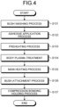
- FIG. 4 is a flowchart illustrating a flow of the bush bonding process, according to the first embodiment.
- Step S101 the bush 31 is washed (Step S101).
- the first member 311 and second member 312 of the bush 31 are washed by a washer 101.
- the first member 311 and the second member 312 are subjected to a drying process.
- an adhesive is applied to the first member 311 and second member 312 (Step S102: an adhesive application step).
- the adhesive is applied, through a nozzle 102, to surfaces of the first member 311 and second member 312, the surfaces being where the body portion is to be bonded to.
- the first member 311 and the second member 312 are subjected to a drying process. Thereafter, the first member 311 and the second member 312 are set in a jig 103.
- the jig 103 includes, for example, a first jig 103a to hold the first member 311 and a second jig 103b to hold the second member 312.
- FIG. 5 is a diagram illustrating a bush preheating process.
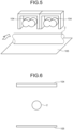
- FIG. 6 and FIG. 7 are diagrams illustrating arrangement of heaters and a reflective plate.
- FIG. 6 is a diagram of heated part of the body portion 2, the heated part being viewed in a longitudinal direction of the heated part.
- FIG. 7 is a diagram of the heated part of the body portion 2, the heated part being viewed in a direction perpendicular to the longitudinal direction of the heated part, the direction being in a longitudinal direction of near-infrared lamps.
- the body portion 2 is preheated using two near-infrared lamps 104 that emit near-infrared rays and a reflective plate 105.
- the near-infrared lamps 104 extend perpendicularly to the longitudinal direction of the heated part of the body portion 2 and are provided on the same side of the body portion 2.
- the reflective plate 105 has a reflective surface that reflects heat and light and the reflective plate 105 is provided at a position where the reflective surface is opposed to the near-infrared lamps 104, with the body portion 2 therebetween.
- the heated part of the body portion 2 is irradiated with near-infrared rays from the near-infrared lamps 104 and opposite part of the body portion 2 is irradiated with the near-infrared rays reflected by the reflective plate 105, the opposite part being on the opposite side of the body portion 2, the opposite side being opposite to the side toward the near-infrared lamps 104.
- Step S104 a surface treatment step.
- the body portion 2 is subjected to surface treatment through the plasma treatment.
- a surface of the body portion 2 is subjected to the plasma treatment by means of plasma nozzles 106.
- the plasma treatment may be performed in an unheated space at normal temperature or may be performed in a space that has been heated to room temperature or higher.
- Step S105 a second heating step.
- a main heating process for example, induction heating (IH) is used.
- IH induction heating
- the surfaces of the first member 311 and second member 312 are heated by IH coils 107, the surfaces being where the body portion is to be bonded to.
- the body portion 2 is heated for about a few tens of seconds. Temperatures for the main heating process and heating process are set as appropriate, depending on the types of the bush 31 and adhesive.
- a target temperature to be reached for the body portion 2 in the preheating process is set to, for example, a temperature higher than room temperature (outside temperature) and 30% of the main heating target temperature or higher and 90% of the main heating target temperature or lower.
- the target temperature for the heated part is set to a temperature ranging from 150°C to 300°C.
- FIG. 8 is a diagram illustrating a bush bonding process. As illustrated in FIG. 8 , the first jig 103a holding the first member 311 and the second jig 103b holding the second member 312 are attached to heated part 2a of the body portion 2. An adhesive 313 has already been applied to part of the first member 311 and second member 312, the part being part to be bonded to the body portion 2.
- Step S107 a compression bonding holding process for bonding the bush 31 to the body portion 2 is performed.
- the compression bonding holding process is maintained in the attached state until vulcanization bonding is completed, for example. In this state, the body portion 2 and the bush 31 are bonded to each other by heat in the body portion 2 and pressure.
- the first jig 103a is removed from the first member 311
- the second jig 103b is removed from the second member 312
- the stabilizer 1 having the bush 31 firmly fixed to the body portion 2 is thereby obtained (see (h) in FIG. 3 ).
- the above described first embodiment of the present invention enables the heated part to be heated to a high temperature in the main heating by the preheating before the main heating.
- the first embodiment unfailingly enables the bush 31 to be bonded to the stabilizer regardless of the outside temperature while minimizing reduction in the productivity.
- the first embodiment unfailingly enables the body portion 2 to be heated because the preheating process is performed using near-infrared rays high in heat transfer efficiency.
- FIG. 9 and FIG. 10 are diagrams illustrating arrangement of a heater and a reflective plate, according to the first modified example of the first embodiment.
- FIG. 9 is a diagram of heated part of the body portion 2, the heated part being viewed in a longitudinal direction of the heated part.
- FIG. 10 is a diagram of the heated part of the body portion 2, the heated part being viewed in a direction perpendicular to the longitudinal direction of the heated part, the direction being in a longitudinal direction of a near-infrared lamp.
- the body portion 2 is preheated using one near-infrared lamp 104 that emits near-infrared rays and the reflective plate 105.
- the near-infrared lamp 104 is provided above the heated part of the body portion 2.
- the reflective plate 105 is provided at a position where its reflective surface is opposed to the near-infrared lamp 104, with the body portion 2 therebetween.
- the heated part of the body portion 2 is irradiated with near-infrared rays from the near-infrared lamp 104 and opposite part of the body portion 2 is irradiated with the near-infrared rays reflected by the reflective plate 105, the opposite part being on the opposite side of the body portion 2, the opposite side being opposite to the side toward the near-infrared lamp 104.
- FIG. 11 and FIG. 12 are diagrams illustrating arrangement of heaters and a reflective plate, according to the second modified example of the first embodiment.
- FIG. 11 is a diagram of heated part of the body portion 2, the heated part being viewed in a longitudinal direction of the heated part.
- FIG. 12 is a diagram of the heated part of the body portion 2, the heated part being viewed in a direction perpendicular to the longitudinal direction of the heated part, the direction being in a longitudinal direction of near-infrared lamps.
- a reflective plate 105A is included, instead of the reflective plate 105 of the first embodiment.
- the reflective plate 105A has a reflective surface curved concavely and is provided at a position where the reflective surface is opposed to the near-infrared lamps 104, with the body portion 2 therebetween.
- the heated part of the body portion 2 is irradiated with near-infrared rays from the near-infrared lamps 104 and opposite part of the body portion 2 is irradiated with the near-infrared rays reflected by the reflective plate 105, the opposite part being on the opposite side of the body portion 2, the opposite side being opposite to the side toward the near-infrared lamps 104. Because the reflective surface is curved and the near-infrared rays are reflected to be directed to the body portion 2, the body portion 2 is able to be heated even more efficiently in this preheating process.
- performing the preheating process for preliminarily heating the part of the body portion 2 before a main heating process in the second modified example unfailingly enables the bush 31 to be bonded to the stabilizer regardless of the outside temperature, the part being where the bush 31 is to be bonded to.
- having the concave reflective surface of the reflective plate 105A to cause the reflected near-infrared rays to concentrate in the body portion 2 in this second modified example enables the opposite side of the body portion 2 to be heated even more unfailingly, the opposite side being opposite to the side toward the near-infrared lamps 104.
- FIG. 13 and FIG. 14 are diagrams illustrating arrangement of a heater and a reflective plate, according to the third modified example of the first embodiment.
- FIG. 13 is a diagram of heated part of the body portion 2, the heated part being viewed in a longitudinal direction of the heated part.
- FIG. 14 is a diagram of the heated part of the body portion 2, the heated part being viewed in a direction perpendicular to the longitudinal direction of the heated part, the direction being in a longitudinal direction of a near-infrared lamp.
- the body portion 2 is preheated using one near-infrared lamp 104 that emits near-infrared rays and the reflective plate 105A.
- the near-infrared lamp 104 is provided above the heated part of the body portion 2.
- the reflective plate 105A is provided at a position where its reflective surface is opposed to the near-infrared lamp 104, with the body portion 2 therebetween.
- the heated part of the body portion 2 is irradiated with near-infrared rays from the near-infrared lamp 104 and opposite part of the body portion 2 is irradiated with the near-infrared rays reflected by the reflective plate 105A, the opposite part being on the opposite side of the body portion 2, the opposite side being opposite to the side toward the near-infrared lamp 104.
- FIG. 15 and FIG. 16 are diagrams illustrating arrangement of heaters and a reflective plate, according to the fourth modified example of the first embodiment.
- FIG. 15 is a diagram of heated part of the body portion 2, the heated part being viewed in a longitudinal direction of the heated part.
- FIG. 16 is a diagram of the heated part of the body portion 2, the heated part being viewed in a direction perpendicular to the longitudinal direction of the heated part, the direction being in a longitudinal direction of near-infrared lamps.
- two near-infrared lamps 104 are included, instead of the reflective plate 105 of the first embodiment.
- the four near-infrared lamps 104 are arranged in groups of two such that the groups are opposed to each other, with the body portion 2 between the groups of two.
- heated part of the body portion 2 is irradiated with near-infrared rays from the near-infrared lamps 104 from both sides of the heated part.
- performing the preheating process for preliminarily heating the part of the body portion 2 before a main heating process in this fourth modified example unfailingly enables the bush 31 to be bonded to the stabilizer regardless of the outside temperature, the part being where the bush 31 is to be bonded to.
- the body portion 2 is able to be heated even more unfailingly by the near-infrared lamp 104 arranged at positions opposed to each other with the body portion 2 between these positions.
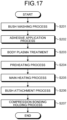
- FIG. 17 is a flowchart illustrating a flow of a bush bonding process, according to the second embodiment.
- the stabilizer 1 according to the second embodiment has the same configuration as the first embodiment.
- a bonding method for the bush 31, according to the second embodiment will be described hereinafter.
- Step S201 the bush 31 is washed (Step S201) and an adhesive is applied to the first member 311 and the second member 312 (Step S202).
- Step S203 plasma treatment of the body portion 2 is performed (Step S203).
- the body portion 2 is subjected to surface treatment through the plasma treatment (see, for example, (e) in FIG. 3 ).
- the body portion 2 is preheated (Step S204). For example, as illustrated by (d) in FIG. 3 , for example, part of the body portion 2 is heated using the two near-infrared lamps 104 that emit near-infrared rays and the reflective plate 105, the part being where the bush 31 is to be bonded to.
- Step S205 the body portion 2 is subjected to a main heating process
- Step S206 a bush attachment process is performed with the first member 311 and the second member 312 set in the jig 103
- Step S207 a compression bonding holding process for bonding the bush 31 to the body portion 2 is performed.
- first jig 103a is removed from the first member 311
- second jig 103b is removed from the second member 312
- compression bonding of the bush 31 to the body portion 2 is thereby completed.
- the above described second embodiment of the present invention enables the heated part to be heated to a high temperature in the main heating regardless of the outside temperature, because the preheating process for preliminarily heating the part of the body portion 2 before the main heating process is performed, the part being where the bush 31 is to be bonded to.
- the second embodiment unfailingly enables the bush 31 to be bonded to the stabilizer regardless of the outside temperature.
- the preheating process and main heating process are successively performed but heating the body portion 2 by the preheating process without temperature monitoring and heating the body portion 2 with the temperature monitored in the main heating process enable heating efficiently and unfailingly.
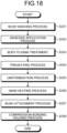
- FIG. 18 is a flowchart illustrating a flow of a bush bonding process, according to the third embodiment.
- the stabilizer 1 according to the third embodiment has the same configuration as the first embodiment.
- a bonding method for the bush 31, according to the third embodiment will be described hereinafter.
- Step S301 the bush 31 is washed (Step S301), an adhesive is applied to the first member 311 and second member 312 (Step S302), the body portion 2 is subjected to plasma treatment (Step S303), and the body portion 2 is subjected to a preheating process (Step S304).
- Step S305 Uniformization of heated part of the body portion 2 is performed after the preheating process (Step S305: a uniformization step).
- the temperature of part where the bush is to be bonded to is uniformized by leaving the heated part to stand.
- Step S306 the body portion 2 is subjected to a main heating process
- Step S307 a bush attachment process is performed with the first member 311 and second member 312 set in the jig 103
- Step S308 a compression bonding holding process for bonding the bush 31 to the body portion 2 is performed.
- first jig 103a is removed from the first member 311
- second jig 103b is removed from the second member 312
- compression bonding of the bush 31 to the body portion 2 is thereby completed.
- the above described third embodiment of the present invention enables the heated part to be heated to a high temperature in the main heating regardless of the outside temperature, because the preheating process for preliminarily heating the part of the body portion 2 before the main heating process is performed, the part being where the bush 31 is to be bonded to.
- the second embodiment unfailingly enables the bush 31 to be bonded to the stabilizer regardless of the outside temperature.
- the third embodiment enables reduction in non-uniformity of the temperature of the part where the bush is to be bonded to, because the heat uniformization process is performed between the preheating process and the main heating process.
- the treatment time for the body plasma treatment of the first embodiment may be adjusted to the time needed for the uniformization.
- near-infrared lamps are used as heating members for the preheating process and IH coils are used as heating members for the main heating process, but the heating members are not limited to these examples, and any publicly known means (for example, heating by electric conduction or heating by use of hot air) may be used and selected as appropriate according to the heating efficiency, for example.
- a bush to be coupled to the body of a vehicle is bonded to a stabilizer, but without being limited to stabilizers, any adherend member that a buffer member is to be bonded to by heating is applicable, the buffer member being between the adherend member and a coupling target and being for buffering collisions between these coupling targets, for example.
- the adherend member include, in addition to stabilizers, spiral springs, leaf springs, torsion bars, and disc springs.
- an insulator is used as a buffer member for a spiral spring.
- a bonding method according to the present invention is suitable for unfailingly bonding a buffer member to an adherend member regardless of outside temperature while minimizing reduction in productivity.
Landscapes
- Engineering & Computer Science (AREA)
- Mechanical Engineering (AREA)
- Physics & Mathematics (AREA)
- Electromagnetism (AREA)
- Health & Medical Sciences (AREA)
- Toxicology (AREA)
- Organic Chemistry (AREA)
- Thermal Sciences (AREA)
- Chemical & Material Sciences (AREA)
- Plasma & Fusion (AREA)
- Lining Or Joining Of Plastics Or The Like (AREA)
- Adhesives Or Adhesive Processes (AREA)
- Vibration Dampers (AREA)
- Vehicle Body Suspensions (AREA)
- Standing Axle, Rod, Or Tube Structures Coupled By Welding, Adhesion, Or Deposition (AREA)
Abstract
Description
- The present invention relates to a bonding method.
- Stabilizers used in vehicles, for example, are mounted in the vehicles and stabilize postures of the vehicles. A bush serving as a buffer member that buffers collisions between a stabilizer and the body of a vehicle, for example, is provided at a joint between the stabilizer and the body, and the stabilizer and the body of the vehicle are coupled to each other via the bush. The bush is formed using an elastic member, such as rubber, and reduces transmission of vibration of the stabilizer to the body. In general, the bush is made of two members and is attached to the stabilizer by vulcanization bonding after an adhesive is applied to a contact surface of an adherend member, the stabilizer (see, for example, Patent Literature 1). In the vulcanization bonding, part of the stabilizer is heated, the part being where the bush is to be bonded. In a heating method therefor, an induction heating coil is adopted, for example (see,
Patent Literature 2, for example). -
- Patent Literature 1:
Japanese Patent No. 6542516 - Patent Literature 2:
Japanese Patent No. 6832312 - The temperature of the stabilizer due to the heating depends largely on the outside temperature and the heating time has thus needed to be changed for each season, for example. Such readjustment of the heating condition has led to increase in the number of operation steps and operating time and thus to reduction in the productivity.
- The present invention has been made in view of the above and an object thereof is to provide a bonding method that unfailingly enables a buffer member to be bonded to an adherend member regardless of outside temperature while minimizing reduction in productivity. Solution to Problem
- To solve the above-described problem and achieve the object, a bonding method according to the present invention for bonding a buffer member to an adherend member includes: an adhesive application step of applying an adhesive to a part of the buffer member, the part being bonded to the adherend member; a first heating step of heating a part of the adherend member, the part being bonded to the buffer member; a second heating step of heating the part of the adherend member after the first heating step; and an attachment step of attaching the buffer member to the adherend member after the second heating step.
- Moreover, the above-described bonding method according to the present invention further includes a surface treatment step of performing surface treatment to the adherend member before the second heating step.
- Moreover, the above-described bonding method according to the present invention further includes a uniformization step of uniformizing a temperature of the adherend member after the first heating step.
- Moreover, in the above-described bonding method according to the present invention, the first heating step includes heating the adherend member using a near-infrared lamp, and the second heating step includes heating the adherend member by induction heating.
- The present invention has an effect of unfailingly enabling a buffer member to be bonded to a stabilizer regardless of outside temperature while minimizing reduction in productivity.
-
-
FIG. 1 is a perspective view of an example of a stabilizer manufactured, in a first embodiment of the present invention. -
FIG. 2 is a diagram illustrating a configuration of the stabilizer illustrated inFIG. 1 , the configuration being near a bush member. -
FIG. 3 is a diagram illustrating a bush bonding process for the stabilizer illustrated inFIG. 1 . -
FIG. 4 is a flowchart illustrating a flow of the bush bonding process, according to the first embodiment. -
FIG. 5 is a diagram illustrating a bush preheating process. -
FIG. 6 is a diagram (No. 1) illustrating arrangement of heaters and a reflective plate. -
FIG. 7 is a diagram (No. 2) illustrating the arrangement of the heaters and the reflective plate. -
FIG. 8 is a diagram illustrating the bush bonding process. -
FIG. 9 is a diagram (No. 1) illustrating arrangement of a heater and a reflective plate, according to a first modified example of the first embodiment. -
FIG. 10 is a diagram (No. 2) illustrating the arrangement of the heater and the reflective plate, according to the first modified example of the first embodiment. -
FIG. 11 is a diagram (No. 1) illustrating arrangement of heaters and a reflective plate, according to a second modified example of the first embodiment. -
FIG. 12 is a diagram (No. 2) illustrating the arrangement of the heaters and the reflective plate, according to the second modified example of the first embodiment. -
FIG. 13 is a diagram (No. 1) illustrating arrangement of a heater and a reflective plate, according to a third modified example of the first embodiment. -
FIG. 14 is a diagram (No. 2) illustrating the arrangement of the heater and the reflective plate, according to the third modified example of the first embodiment. -
FIG. 15 is a diagram (No. 1) illustrating arrangement of heaters, according to a fourth modified example of the first embodiment. -
FIG. 16 is a diagram (No. 2) illustrating the arrangement of the heaters, according to the fourth modified example of the first embodiment. -
FIG. 17 is a flowchart illustrating a flow of a bush bonding process, according to a second embodiment. -
FIG. 18 is a flowchart illustrating a flow of a bush bonding process, according to a third embodiment. Description of Embodiments - Modes (hereinafter, referred to as "embodiments") for implementing the present invention will hereinafter be described by reference to the appended drawings. The drawings are schematic, a relation between a thickness and a width of each portion and ratios among thicknesses of respective portions may be different from the actual relation and ratios, and the drawings may also include a portion that differs in its dimensional relations or ratios among the drawings.
-
FIG. 1 is a perspective view of an example of a stabilizer manufactured, in a first embodiment of the present invention.FIG. 2 is a diagram illustrating a configuration of the stabilizer illustrated inFIG. 1 , the configuration being near a bush member. Astabilizer 1 has abody portion 2 bent at both ends thereof and linearly extending at a central portion thereof, and abush member 3 attached to thebody portion 2. - The
body portion 2 extends in a columnar shape, for example, a cylindrical shape, and is bent at both end portions thereof. Thebody portion 2 may be solid or may be hollow. Thebody portion 2 is formed of any of: metals and various types of fiber (for example, carbon fiber). - In a case where the
stabilizer 1 is provided in an automobile, for example, one of end portions of thestabilizer 1 is connected to one of suspensions arranged to right and left and the other one of the end portions is connected to the other one of the suspensions. These end portions are then fixed to the suspensions via through holes. Furthermore, thestabilizer 1 is fixed also to the body of the automobile via thebush member 3. - The
stabilizer 1 is manufactured by processing of a base material. For example, after a base material that is column-shaped is bent, pressure is applied to both end portions of the base material so that the end portions become plate-shaped, and through holes are then formed in the end portions. - The
bush member 3 has abush 31 and abracket 32. Thebracket 32 is attached to the body of the automobile via, for example, screws, and supports thebody portion 2 via thebush 31. - The
bush 31 is formed using an elastic material, such as rubber or a resin having elasticity, and functions as a buffer member that buffers collisions between thestabilizer 1 and the body, for example. Thebush 31 includes two members (afirst member 311 and a second member 312). Thebush 31 is formed by bonding of thefirst member 311 andsecond member 312 to thebody portion 2, with thebody portion 2 interposed between thefirst member 311 andsecond member 312. - A bonding process of bonding the above described
bush 31 to thebody portion 2 will be described next by reference toFIG. 3 to FIG. 8 .FIG. 3 is a diagram illustrating the bush bonding process for the stabilizer illustrated inFIG. 1 .FIG. 4 is a flowchart illustrating a flow of the bush bonding process, according to the first embodiment. - Firstly, the
bush 31 is washed (Step S101). For example, as illustrated by (a) inFIG. 3 , thefirst member 311 andsecond member 312 of thebush 31 are washed by awasher 101. After being washed, thefirst member 311 and thesecond member 312 are subjected to a drying process. - After the washing process, an adhesive is applied to the
first member 311 and second member 312 (Step S102: an adhesive application step). For example, as illustrated by (b) inFIG. 3 , the adhesive is applied, through anozzle 102, to surfaces of thefirst member 311 andsecond member 312, the surfaces being where the body portion is to be bonded to. After the application of the adhesive, thefirst member 311 and thesecond member 312 are subjected to a drying process. Thereafter, thefirst member 311 and thesecond member 312 are set in ajig 103. Thejig 103 includes, for example, afirst jig 103a to hold thefirst member 311 and asecond jig 103b to hold thesecond member 312. - As to the
body portion 2, a preheating process for part of thebody portion 2 is performed, the part being where thebush 31 is to be bonded to (Step S103: a first heating step, see (d) inFIG. 3 ).FIG. 5 is a diagram illustrating a bush preheating process.FIG. 6 andFIG. 7 are diagrams illustrating arrangement of heaters and a reflective plate.FIG. 6 is a diagram of heated part of thebody portion 2, the heated part being viewed in a longitudinal direction of the heated part.FIG. 7 is a diagram of the heated part of thebody portion 2, the heated part being viewed in a direction perpendicular to the longitudinal direction of the heated part, the direction being in a longitudinal direction of near-infrared lamps. - In this first embodiment, the
body portion 2 is preheated using two near-infrared lamps 104 that emit near-infrared rays and areflective plate 105. The near-infrared lamps 104 extend perpendicularly to the longitudinal direction of the heated part of thebody portion 2 and are provided on the same side of thebody portion 2. Furthermore, thereflective plate 105 has a reflective surface that reflects heat and light and thereflective plate 105 is provided at a position where the reflective surface is opposed to the near-infrared lamps 104, with thebody portion 2 therebetween. In the preheating process, the heated part of thebody portion 2 is irradiated with near-infrared rays from the near-infrared lamps 104 and opposite part of thebody portion 2 is irradiated with the near-infrared rays reflected by thereflective plate 105, the opposite part being on the opposite side of thebody portion 2, the opposite side being opposite to the side toward the near-infrared lamps 104. - After the preheating process, the
body portion 2 is subjected to plasma treatment (Step S104: a surface treatment step). Thebody portion 2 is subjected to surface treatment through the plasma treatment. For example, as illustrated by (e) inFIG. 3 , a surface of thebody portion 2 is subjected to the plasma treatment by means ofplasma nozzles 106. For example, the plasma treatment may be performed in an unheated space at normal temperature or may be performed in a space that has been heated to room temperature or higher. - After the plasma treatment, the
body portion 2 is subjected to a main heating process (Step S105: a second heating step). For this main heating process, for example, induction heating (IH) is used. For example, as illustrated by (f) inFIG. 3 , the surfaces of thefirst member 311 andsecond member 312 are heated byIH coils 107, the surfaces being where the body portion is to be bonded to. For example, in the main heating process, thebody portion 2 is heated for about a few tens of seconds. Temperatures for the main heating process and heating process are set as appropriate, depending on the types of thebush 31 and adhesive. In contrast to a target temperature to be reached in the main heating process, a target temperature to be reached for thebody portion 2 in the preheating process is set to, for example, a temperature higher than room temperature (outside temperature) and 30% of the main heating target temperature or higher and 90% of the main heating target temperature or lower. In the main heating process, for example, the target temperature for the heated part is set to a temperature ranging from 150°C to 300°C. - In a state where the
first member 311 and thesecond member 312 have been set in thejig 103 and thebody portion 2 has been subjected to the main heating process, a bush attachment process is performed (Step S106: see (g) inFIG. 3 ).FIG. 8 is a diagram illustrating a bush bonding process. As illustrated inFIG. 8 , thefirst jig 103a holding thefirst member 311 and thesecond jig 103b holding thesecond member 312 are attached toheated part 2a of thebody portion 2. An adhesive 313 has already been applied to part of thefirst member 311 andsecond member 312, the part being part to be bonded to thebody portion 2. - After the
jig 103 has been attached to thebody portion 2, a compression bonding holding process for bonding thebush 31 to thebody portion 2 is performed (Step S107). The compression bonding holding process is maintained in the attached state until vulcanization bonding is completed, for example. In this state, thebody portion 2 and thebush 31 are bonded to each other by heat in thebody portion 2 and pressure. - Thereafter, the
first jig 103a is removed from thefirst member 311, thesecond jig 103b is removed from thesecond member 312, and thestabilizer 1 having thebush 31 firmly fixed to thebody portion 2 is thereby obtained (see (h) inFIG. 3 ). - Because the preheating process for preliminarily heating the part of the
body portion 2 is performed before the main heating process, the part being where thebush 31 is to be bonded to, the above described first embodiment of the present invention enables the heated part to be heated to a high temperature in the main heating by the preheating before the main heating. The first embodiment unfailingly enables thebush 31 to be bonded to the stabilizer regardless of the outside temperature while minimizing reduction in the productivity. - Furthermore, the first embodiment unfailingly enables the
body portion 2 to be heated because the preheating process is performed using near-infrared rays high in heat transfer efficiency. - A first modified example of the first embodiment of the present invention will be described next by reference to
FIG. 9 and FIG. 10. FIG. 9 and FIG. 10 are diagrams illustrating arrangement of a heater and a reflective plate, according to the first modified example of the first embodiment.FIG. 9 is a diagram of heated part of thebody portion 2, the heated part being viewed in a longitudinal direction of the heated part.FIG. 10 is a diagram of the heated part of thebody portion 2, the heated part being viewed in a direction perpendicular to the longitudinal direction of the heated part, the direction being in a longitudinal direction of a near-infrared lamp. - In this first modified example, the
body portion 2 is preheated using one near-infrared lamp 104 that emits near-infrared rays and thereflective plate 105. The near-infrared lamp 104 is provided above the heated part of thebody portion 2. Furthermore, thereflective plate 105 is provided at a position where its reflective surface is opposed to the near-infrared lamp 104, with thebody portion 2 therebetween. In a preheating process, the heated part of thebody portion 2 is irradiated with near-infrared rays from the near-infrared lamp 104 and opposite part of thebody portion 2 is irradiated with the near-infrared rays reflected by thereflective plate 105, the opposite part being on the opposite side of thebody portion 2, the opposite side being opposite to the side toward the near-infrared lamp 104. - Even in a case where the number of near-
infrared lamps 104 is one like in this first modified example, performing the preheating process for preliminarily heating the part of thebody portion 2 before a main heating process unfailingly enables thebush 31 to be bonded to the stabilizer regardless of the outside temperature, the part being where thebush 31 is to be bonded to. - A second modified example of the first embodiment of the present invention will be described next by reference to
FIG. 11 and FIG. 12. FIG. 11 and FIG. 12 are diagrams illustrating arrangement of heaters and a reflective plate, according to the second modified example of the first embodiment.FIG. 11 is a diagram of heated part of thebody portion 2, the heated part being viewed in a longitudinal direction of the heated part.FIG. 12 is a diagram of the heated part of thebody portion 2, the heated part being viewed in a direction perpendicular to the longitudinal direction of the heated part, the direction being in a longitudinal direction of near-infrared lamps. In this second modified example, areflective plate 105A is included, instead of thereflective plate 105 of the first embodiment. - The
reflective plate 105A has a reflective surface curved concavely and is provided at a position where the reflective surface is opposed to the near-infrared lamps 104, with thebody portion 2 therebetween. In a preheating process, the heated part of thebody portion 2 is irradiated with near-infrared rays from the near-infrared lamps 104 and opposite part of thebody portion 2 is irradiated with the near-infrared rays reflected by thereflective plate 105, the opposite part being on the opposite side of thebody portion 2, the opposite side being opposite to the side toward the near-infrared lamps 104. Because the reflective surface is curved and the near-infrared rays are reflected to be directed to thebody portion 2, thebody portion 2 is able to be heated even more efficiently in this preheating process. - Similarly to the first embodiment, performing the preheating process for preliminarily heating the part of the
body portion 2 before a main heating process in the second modified example unfailingly enables thebush 31 to be bonded to the stabilizer regardless of the outside temperature, the part being where thebush 31 is to be bonded to. - Furthermore, having the concave reflective surface of the
reflective plate 105A to cause the reflected near-infrared rays to concentrate in thebody portion 2 in this second modified example enables the opposite side of thebody portion 2 to be heated even more unfailingly, the opposite side being opposite to the side toward the near-infrared lamps 104. - A third modified example of the first embodiment of the present invention will be described next by reference to
FIG. 13 and FIG. 14. FIG. 13 and FIG. 14 are diagrams illustrating arrangement of a heater and a reflective plate, according to the third modified example of the first embodiment.FIG. 13 is a diagram of heated part of thebody portion 2, the heated part being viewed in a longitudinal direction of the heated part.FIG. 14 is a diagram of the heated part of thebody portion 2, the heated part being viewed in a direction perpendicular to the longitudinal direction of the heated part, the direction being in a longitudinal direction of a near-infrared lamp. - In this third modified example, the
body portion 2 is preheated using one near-infrared lamp 104 that emits near-infrared rays and thereflective plate 105A. The near-infrared lamp 104 is provided above the heated part of thebody portion 2. Furthermore, thereflective plate 105A is provided at a position where its reflective surface is opposed to the near-infrared lamp 104, with thebody portion 2 therebetween. In a preheating process, the heated part of thebody portion 2 is irradiated with near-infrared rays from the near-infrared lamp 104 and opposite part of thebody portion 2 is irradiated with the near-infrared rays reflected by thereflective plate 105A, the opposite part being on the opposite side of thebody portion 2, the opposite side being opposite to the side toward the near-infrared lamp 104. - Even in a case where the number of near-
infrared lamps 104 is one like in this third modified example, performing the preheating process for preliminarily heating the part of thebody portion 2 before a main heating process unfailingly enables thebush 31 to be bonded to the stabilizer regardless of the outside temperature, the part being where thebush 31 is to be bonded to. - Furthermore, similarly to the second modified example, having the concave reflective surface of the
reflective plate 105A to cause the reflected near-infrared rays to concentrate in thebody portion 2 in this third modified example enables the opposite side of thebody portion 2 to be heated even more unfailingly, the opposite side being opposite to the side toward the near-infrared lamp 104. - A fourth modified example of the first embodiment of the present invention will be described next by reference to
FIG. 15 and FIG. 16. FIG. 15 and FIG. 16 are diagrams illustrating arrangement of heaters and a reflective plate, according to the fourth modified example of the first embodiment.FIG. 15 is a diagram of heated part of thebody portion 2, the heated part being viewed in a longitudinal direction of the heated part.FIG. 16 is a diagram of the heated part of thebody portion 2, the heated part being viewed in a direction perpendicular to the longitudinal direction of the heated part, the direction being in a longitudinal direction of near-infrared lamps. In this fourth modified example, two near-infrared lamps 104 are included, instead of thereflective plate 105 of the first embodiment. - In this fourth modified example, the four near-
infrared lamps 104 are arranged in groups of two such that the groups are opposed to each other, with thebody portion 2 between the groups of two. In a preheating process, heated part of thebody portion 2 is irradiated with near-infrared rays from the near-infrared lamps 104 from both sides of the heated part. - Similarly to the first embodiment, performing the preheating process for preliminarily heating the part of the
body portion 2 before a main heating process in this fourth modified example unfailingly enables thebush 31 to be bonded to the stabilizer regardless of the outside temperature, the part being where thebush 31 is to be bonded to. - Furthermore, the
body portion 2 is able to be heated even more unfailingly by the near-infrared lamp 104 arranged at positions opposed to each other with thebody portion 2 between these positions. - A second embodiment of the present invention will be described next by reference to
FIG. 17. FIG. 17 is a flowchart illustrating a flow of a bush bonding process, according to the second embodiment. Thestabilizer 1 according to the second embodiment has the same configuration as the first embodiment. A bonding method for thebush 31, according to the second embodiment will be described hereinafter. - In the bonding method according to the second embodiment, similarly to Steps S101 and S102 in
FIG. 4 described above, thebush 31 is washed (Step S201) and an adhesive is applied to thefirst member 311 and the second member 312 (Step S202). - As to the
body portion 2, plasma treatment of thebody portion 2 is performed (Step S203). Thebody portion 2 is subjected to surface treatment through the plasma treatment (see, for example, (e) inFIG. 3 ). - After the plasma treatment, the
body portion 2 is preheated (Step S204). For example, as illustrated by (d) inFIG. 3 , for example, part of thebody portion 2 is heated using the two near-infrared lamps 104 that emit near-infrared rays and thereflective plate 105, the part being where thebush 31 is to be bonded to. - After the preheating process, similarly to Steps S105 to S107 in
FIG. 4 described above, thebody portion 2 is subjected to a main heating process (Step S205), a bush attachment process is performed with thefirst member 311 and thesecond member 312 set in the jig 103 (Step S206), and a compression bonding holding process for bonding thebush 31 to thebody portion 2 is performed (Step S207). - Thereafter, the
first jig 103a is removed from thefirst member 311, thesecond jig 103b is removed from thesecond member 312, and compression bonding of thebush 31 to thebody portion 2 is thereby completed. - Similarly to the first embodiment, the above described second embodiment of the present invention enables the heated part to be heated to a high temperature in the main heating regardless of the outside temperature, because the preheating process for preliminarily heating the part of the
body portion 2 before the main heating process is performed, the part being where thebush 31 is to be bonded to. The second embodiment unfailingly enables thebush 31 to be bonded to the stabilizer regardless of the outside temperature. - In this second embodiment of the present invention, the preheating process and main heating process are successively performed but heating the
body portion 2 by the preheating process without temperature monitoring and heating thebody portion 2 with the temperature monitored in the main heating process enable heating efficiently and unfailingly. - A third embodiment of the present invention will be described next by reference to
FIG. 18. FIG. 18 is a flowchart illustrating a flow of a bush bonding process, according to the third embodiment. Thestabilizer 1 according to the third embodiment has the same configuration as the first embodiment. A bonding method for thebush 31, according to the third embodiment will be described hereinafter. - In the bonding method according to the third embodiment, similarly to Steps S201 to S204 in
FIG. 17 described above, thebush 31 is washed (Step S301), an adhesive is applied to thefirst member 311 and second member 312 (Step S302), thebody portion 2 is subjected to plasma treatment (Step S303), and thebody portion 2 is subjected to a preheating process (Step S304). - Uniformization of heated part of the
body portion 2 is performed after the preheating process (Step S305: a uniformization step). In the uniformization process, the temperature of part where the bush is to be bonded to is uniformized by leaving the heated part to stand. - After the uniformization process, similarly to Steps S205 to S207 in
FIG. 17 described above, thebody portion 2 is subjected to a main heating process (Step S306), a bush attachment process is performed with thefirst member 311 andsecond member 312 set in the jig 103 (Step S307), and a compression bonding holding process for bonding thebush 31 to thebody portion 2 is performed (Step S308). - Thereafter, the
first jig 103a is removed from thefirst member 311, thesecond jig 103b is removed from thesecond member 312, and compression bonding of thebush 31 to thebody portion 2 is thereby completed. - Similarly to the first and second embodiments, the above described third embodiment of the present invention enables the heated part to be heated to a high temperature in the main heating regardless of the outside temperature, because the preheating process for preliminarily heating the part of the
body portion 2 before the main heating process is performed, the part being where thebush 31 is to be bonded to. The second embodiment unfailingly enables thebush 31 to be bonded to the stabilizer regardless of the outside temperature. - Furthermore, the third embodiment enables reduction in non-uniformity of the temperature of the part where the bush is to be bonded to, because the heat uniformization process is performed between the preheating process and the main heating process.
- In a case where the body plasma treatment is performed in the uniformization process in this third embodiment, the treatment time for the body plasma treatment of the first embodiment (
FIG. 4 : Step S104) may be adjusted to the time needed for the uniformization. - Modes for implementing the present invention have been described thus far, but the present invention is not to be limited only to the above described embodiments. For example, the present invention is applicable to products manufactured by a thermocompression bonding process.
- Furthermore, in the examples described above with respect to the embodiments, near-infrared lamps are used as heating members for the preheating process and IH coils are used as heating members for the main heating process, but the heating members are not limited to these examples, and any publicly known means (for example, heating by electric conduction or heating by use of hot air) may be used and selected as appropriate according to the heating efficiency, for example.
- Furthermore, in the examples described above with respect to the embodiments, a bush to be coupled to the body of a vehicle is bonded to a stabilizer, but without being limited to stabilizers, any adherend member that a buffer member is to be bonded to by heating is applicable, the buffer member being between the adherend member and a coupling target and being for buffering collisions between these coupling targets, for example. Examples of the adherend member include, in addition to stabilizers, spiral springs, leaf springs, torsion bars, and disc springs. For example, an insulator is used as a buffer member for a spiral spring.
- The present invention may thus include various embodiments not described herein, and various design changes, for example, may be made without departing from the technical ideas determined by the claims.
- As described hereinbefore, a bonding method according to the present invention is suitable for unfailingly bonding a buffer member to an adherend member regardless of outside temperature while minimizing reduction in productivity.
-
- 1 STABILIZER
- 2 BODY PORTION
- 3 BUSH MEMBER
- 31 BUSH
- 32 BRACKET
- 101 WASHER
- 102 NOZZLE
- 103 JIG
- 103a FIRST JIG
- 103b SECOND JIG
- 104 NEAR-INFRARED LAMP
- 105, 105A REFLECTIVE PLATE
- 106 PLASMA NOZZLE
- 107 IH COIL
- 311 FIRST MEMBER
- 312 SECOND MEMBER
Claims (4)
- A bonding method for bonding a buffer member to an adherend member, the bonding method comprising:an adhesive application step of applying an adhesive to a part of the buffer member, the part being bonded to the adherend member;a first heating step of heating a part of the adherend member, the part being bonded to the buffer member;a second heating step of heating the part of the adherend member after the first heating step; andan attachment step of attaching the buffer member to the adherend member after the second heating step.
- The bonding method according to claim 1, further comprising a surface treatment step of performing surface treatment to the adherend member before the second heating step.
- The bonding method according to claim 1 or 2, further comprising a uniformization step of uniformizing a temperature of the adherend member after the first heating step.
- The bonding method according to any one of claims 1 to 3, whereinthe first heating step includes heating the adherend member using a near-infrared lamp, andthe second heating step includes heating the adherend member by induction heating.
Applications Claiming Priority (2)
| Application Number | Priority Date | Filing Date | Title |
|---|---|---|---|
| JP2021167014A JP7849158B2 (en) | 2021-10-11 | 2021-10-11 | Adhesion method |
| PCT/JP2022/037448 WO2023063211A1 (en) | 2021-10-11 | 2022-10-06 | Bonding method |
Publications (3)
| Publication Number | Publication Date |
|---|---|
| EP4417400A1 true EP4417400A1 (en) | 2024-08-21 |
| EP4417400A4 EP4417400A4 (en) | 2024-08-21 |
| EP4417400B1 EP4417400B1 (en) | 2025-08-20 |
Family
ID=85987467
Family Applications (1)
| Application Number | Title | Priority Date | Filing Date |
|---|---|---|---|
| EP22880906.7A Active EP4417400B1 (en) | 2021-10-11 | 2022-10-06 | Bonding method |
Country Status (8)
| Country | Link |
|---|---|
| US (1) | US12472696B2 (en) |
| EP (1) | EP4417400B1 (en) |
| JP (1) | JP7849158B2 (en) |
| CN (1) | CN117897458A (en) |
| ES (1) | ES3042102T3 (en) |
| HU (1) | HUE072663T2 (en) |
| MX (1) | MX2024003833A (en) |
| WO (1) | WO2023063211A1 (en) |
Family Cites Families (9)
| Publication number | Priority date | Publication date | Assignee | Title |
|---|---|---|---|---|
| US7041193B2 (en) * | 2003-05-14 | 2006-05-09 | L & L Products, Inc. | Method of adhering members and an assembly formed thereby |
| JP4004512B2 (en) | 2005-04-15 | 2007-11-07 | 東洋ゴム工業株式会社 | Manufacturing method of stabilizer bar with rubber bush |
| JP6542516B2 (en) | 2014-08-28 | 2019-07-10 | 三菱製鋼株式会社 | Method of manufacturing stabilizer bar with rubber bush |
| JP5923155B2 (en) * | 2014-10-28 | 2016-05-24 | 日本発條株式会社 | Stabilizer manufacturing apparatus and method |
| KR101858494B1 (en) * | 2016-03-03 | 2018-05-16 | 주식회사 건화 | metal pipe and rubber bush bonding adhesion method |
| WO2018025543A1 (en) | 2016-08-03 | 2018-02-08 | 日本発條株式会社 | Vehicle spring production method and vehicle spring |
| JP6731318B2 (en) | 2016-08-31 | 2020-07-29 | 住友理工株式会社 | Method of manufacturing stabilizer bar with stabilizer bush, jig for stabilizer bush bonding, stabilizer bar bonded product of stabilizer bar |
| JP2018087010A (en) | 2018-02-20 | 2018-06-07 | 三菱製鋼株式会社 | Manufacturing method of stabilizer bar with rubber bush |
| JP6832312B2 (en) | 2018-06-06 | 2021-02-24 | 島田理化工業株式会社 | Induction heating coil |
-
2021
- 2021-10-11 JP JP2021167014A patent/JP7849158B2/en active Active
-
2022
- 2022-10-06 ES ES22880906T patent/ES3042102T3/en active Active
- 2022-10-06 WO PCT/JP2022/037448 patent/WO2023063211A1/en not_active Ceased
- 2022-10-06 MX MX2024003833A patent/MX2024003833A/en unknown
- 2022-10-06 EP EP22880906.7A patent/EP4417400B1/en active Active
- 2022-10-06 HU HUE22880906A patent/HUE072663T2/en unknown
- 2022-10-06 US US18/684,869 patent/US12472696B2/en active Active
- 2022-10-06 CN CN202280059344.2A patent/CN117897458A/en active Pending
Also Published As
| Publication number | Publication date |
|---|---|
| US20240342999A1 (en) | 2024-10-17 |
| US12472696B2 (en) | 2025-11-18 |
| JP2023057464A (en) | 2023-04-21 |
| JP7849158B2 (en) | 2026-04-21 |
| MX2024003833A (en) | 2024-04-15 |
| ES3042102T3 (en) | 2025-11-18 |
| CN117897458A (en) | 2024-04-16 |
| HUE072663T2 (en) | 2025-12-28 |
| EP4417400B1 (en) | 2025-08-20 |
| WO2023063211A1 (en) | 2023-04-20 |
Similar Documents
| Publication | Publication Date | Title |
|---|---|---|
| CN1285460C (en) | Ultrasonic vibration assisting resistance implantation welding method for thermoplastic resin base composite material | |
| US10124646B2 (en) | Method of manufacturing rubber-bush-provided stabilizer bar and rubber-bush-provided stabilizer bar | |
| US20210129208A1 (en) | Apparatus and methods for installing composite rivets | |
| US5645676A (en) | Rework fixture for applying adhesive-coated mirror buttons | |
| US10259285B2 (en) | Stabilizer manufacturing apparatus and stabilizer manufacturing method | |
| US20170312988A1 (en) | Apparatus and method for manufacturing stabilizer | |
| EP4417400B1 (en) | Bonding method | |
| CN106163770B (en) | Resistive implant welding of carbon fiber thermoplastics using highly conductive mesh | |
| CN103380031B (en) | Method for producing wiper blade and wiper blade for wiping glass | |
| US7543683B2 (en) | Vehicle resonator structure and attachment method | |
| WO2009094595A1 (en) | Metal/composite joint with attachment projections, and method of joining | |
| CN103965792B (en) | Air adhering method | |
| KR102016914B1 (en) | Hot Setting Jig Using Resistance Heating for Coil Spring of Car suspension | |
| KR101795256B1 (en) | Combining apparatus for vehicle body parts | |
| CN208112994U (en) | An electrified curing machine with a new clamping and pressing device | |
| JP7718115B2 (en) | Joining device and joining method | |
| JP3305739B2 (en) | Method for manufacturing tubular body for vehicle | |
| US12132139B2 (en) | Solar cell panel manufacturing apparatus, solar cell panel manufacturing method, and solar cell panel | |
| JPS6227399Y2 (en) | ||
| WO2012028194A1 (en) | Infrared heating panel | |
| CN119629780A (en) | A manufacturing device and method for PTC heating core | |
| CN120116492A (en) | Equipment for assembling vehicle components | |
| CN120152412A (en) | Mounting parts and semiconductor processing equipment | |
| JP2002337221A (en) | Method and apparatus for manufacturing tubular molded article | |
| JP2012111103A (en) | Method of bonding sheet molding compound (smc) molded product to metal fitting |
Legal Events
| Date | Code | Title | Description |
|---|---|---|---|
| STAA | Information on the status of an ep patent application or granted ep patent |
Free format text: STATUS: THE INTERNATIONAL PUBLICATION HAS BEEN MADE |
|
| PUAI | Public reference made under article 153(3) epc to a published international application that has entered the european phase |
Free format text: ORIGINAL CODE: 0009012 |
|
| STAA | Information on the status of an ep patent application or granted ep patent |
Free format text: STATUS: REQUEST FOR EXAMINATION WAS MADE |
|
| 17P | Request for examination filed |
Effective date: 20240221 |
|
| A4 | Supplementary search report drawn up and despatched |
Effective date: 20240705 |
|
| AK | Designated contracting states |
Kind code of ref document: A1 Designated state(s): AL AT BE BG CH CY CZ DE DK EE ES FI FR GB GR HR HU IE IS IT LI LT LU LV MC ME MK MT NL NO PL PT RO RS SE SI SK SM TR |
|
| DAV | Request for validation of the european patent (deleted) | ||
| DAX | Request for extension of the european patent (deleted) | ||
| GRAP | Despatch of communication of intention to grant a patent |
Free format text: ORIGINAL CODE: EPIDOSNIGR1 |
|
| STAA | Information on the status of an ep patent application or granted ep patent |
Free format text: STATUS: GRANT OF PATENT IS INTENDED |
|
| RIC1 | Information provided on ipc code assigned before grant |
Ipc: B29C 35/08 20060101ALN20250221BHEP Ipc: B29L 31/00 20060101ALN20250221BHEP Ipc: B29L 31/30 20060101ALN20250221BHEP Ipc: B29C 65/52 20060101ALI20250221BHEP Ipc: B29C 65/46 20060101ALI20250221BHEP Ipc: B29C 65/44 20060101ALI20250221BHEP Ipc: B29C 65/14 20060101ALI20250221BHEP Ipc: B29C 65/02 20060101ALI20250221BHEP Ipc: C09J 201/00 20060101ALI20250221BHEP Ipc: C09J 5/06 20060101ALI20250221BHEP Ipc: F16B 11/00 20060101ALI20250221BHEP Ipc: B60G 21/055 20060101ALI20250221BHEP Ipc: B29C 65/48 20060101AFI20250221BHEP |
|
| INTG | Intention to grant announced |
Effective date: 20250314 |
|
| GRAS | Grant fee paid |
Free format text: ORIGINAL CODE: EPIDOSNIGR3 |
|
| GRAA | (expected) grant |
Free format text: ORIGINAL CODE: 0009210 |
|
| STAA | Information on the status of an ep patent application or granted ep patent |
Free format text: STATUS: THE PATENT HAS BEEN GRANTED |
|
| P01 | Opt-out of the competence of the unified patent court (upc) registered |
Free format text: CASE NUMBER: APP_30757/2025 Effective date: 20250626 |
|
| AK | Designated contracting states |
Kind code of ref document: B1 Designated state(s): AL AT BE BG CH CY CZ DE DK EE ES FI FR GB GR HR HU IE IS IT LI LT LU LV MC ME MK MT NL NO PL PT RO RS SE SI SK SM TR |
|
| REG | Reference to a national code |
Ref country code: GB Ref legal event code: FG4D |
|
| REG | Reference to a national code |
Ref country code: CH Ref legal event code: EP |
|
| REG | Reference to a national code |
Ref country code: IE Ref legal event code: FG4D |
|
| REG | Reference to a national code |
Ref country code: DE Ref legal event code: R096 Ref document number: 602022020009 Country of ref document: DE |
|
| PGFP | Annual fee paid to national office [announced via postgrant information from national office to epo] |
Ref country code: HU Payment date: 20250912 Year of fee payment: 4 |
|
| REG | Reference to a national code |
Ref country code: ES Ref legal event code: FG2A Ref document number: 3042102 Country of ref document: ES Kind code of ref document: T3 Effective date: 20251118 |
|
| REG | Reference to a national code |
Ref country code: NL Ref legal event code: MP Effective date: 20250820 |
|
| REG | Reference to a national code |
Ref country code: HU Ref legal event code: AG4A Ref document number: E072663 Country of ref document: HU |
|
| PG25 | Lapsed in a contracting state [announced via postgrant information from national office to epo] |
Ref country code: IS Free format text: LAPSE BECAUSE OF FAILURE TO SUBMIT A TRANSLATION OF THE DESCRIPTION OR TO PAY THE FEE WITHIN THE PRESCRIBED TIME-LIMIT Effective date: 20251220 |
|
| PGFP | Annual fee paid to national office [announced via postgrant information from national office to epo] |
Ref country code: DE Payment date: 20251028 Year of fee payment: 4 |
|
| PG25 | Lapsed in a contracting state [announced via postgrant information from national office to epo] |
Ref country code: NO Free format text: LAPSE BECAUSE OF FAILURE TO SUBMIT A TRANSLATION OF THE DESCRIPTION OR TO PAY THE FEE WITHIN THE PRESCRIBED TIME-LIMIT Effective date: 20251120 |
|
| REG | Reference to a national code |
Ref country code: LT Ref legal event code: MG9D |
|
| PG25 | Lapsed in a contracting state [announced via postgrant information from national office to epo] |
Ref country code: PT Free format text: LAPSE BECAUSE OF FAILURE TO SUBMIT A TRANSLATION OF THE DESCRIPTION OR TO PAY THE FEE WITHIN THE PRESCRIBED TIME-LIMIT Effective date: 20251222 |
|
| PG25 | Lapsed in a contracting state [announced via postgrant information from national office to epo] |
Ref country code: FI Free format text: LAPSE BECAUSE OF FAILURE TO SUBMIT A TRANSLATION OF THE DESCRIPTION OR TO PAY THE FEE WITHIN THE PRESCRIBED TIME-LIMIT Effective date: 20250820 |
|
| PG25 | Lapsed in a contracting state [announced via postgrant information from national office to epo] |
Ref country code: NL Free format text: LAPSE BECAUSE OF FAILURE TO SUBMIT A TRANSLATION OF THE DESCRIPTION OR TO PAY THE FEE WITHIN THE PRESCRIBED TIME-LIMIT Effective date: 20250820 Ref country code: HR Free format text: LAPSE BECAUSE OF FAILURE TO SUBMIT A TRANSLATION OF THE DESCRIPTION OR TO PAY THE FEE WITHIN THE PRESCRIBED TIME-LIMIT Effective date: 20250820 |
|
| PGFP | Annual fee paid to national office [announced via postgrant information from national office to epo] |
Ref country code: FR Payment date: 20251029 Year of fee payment: 4 |
|
| PG25 | Lapsed in a contracting state [announced via postgrant information from national office to epo] |
Ref country code: GR Free format text: LAPSE BECAUSE OF FAILURE TO SUBMIT A TRANSLATION OF THE DESCRIPTION OR TO PAY THE FEE WITHIN THE PRESCRIBED TIME-LIMIT Effective date: 20251121 |
|
| PG25 | Lapsed in a contracting state [announced via postgrant information from national office to epo] |
Ref country code: SE Free format text: LAPSE BECAUSE OF FAILURE TO SUBMIT A TRANSLATION OF THE DESCRIPTION OR TO PAY THE FEE WITHIN THE PRESCRIBED TIME-LIMIT Effective date: 20250820 |
|
| PG25 | Lapsed in a contracting state [announced via postgrant information from national office to epo] |
Ref country code: LV Free format text: LAPSE BECAUSE OF FAILURE TO SUBMIT A TRANSLATION OF THE DESCRIPTION OR TO PAY THE FEE WITHIN THE PRESCRIBED TIME-LIMIT Effective date: 20250820 |
|
| PG25 | Lapsed in a contracting state [announced via postgrant information from national office to epo] |
Ref country code: BG Free format text: LAPSE BECAUSE OF FAILURE TO SUBMIT A TRANSLATION OF THE DESCRIPTION OR TO PAY THE FEE WITHIN THE PRESCRIBED TIME-LIMIT Effective date: 20250820 Ref country code: PL Free format text: LAPSE BECAUSE OF FAILURE TO SUBMIT A TRANSLATION OF THE DESCRIPTION OR TO PAY THE FEE WITHIN THE PRESCRIBED TIME-LIMIT Effective date: 20250820 |
|
| PG25 | Lapsed in a contracting state [announced via postgrant information from national office to epo] |
Ref country code: RS Free format text: LAPSE BECAUSE OF FAILURE TO SUBMIT A TRANSLATION OF THE DESCRIPTION OR TO PAY THE FEE WITHIN THE PRESCRIBED TIME-LIMIT Effective date: 20251120 |
|
| PGFP | Annual fee paid to national office [announced via postgrant information from national office to epo] |
Ref country code: ES Payment date: 20251103 Year of fee payment: 4 |
|
| REG | Reference to a national code |
Ref country code: AT Ref legal event code: MK05 Ref document number: 1826894 Country of ref document: AT Kind code of ref document: T Effective date: 20250820 |
|
| PG25 | Lapsed in a contracting state [announced via postgrant information from national office to epo] |
Ref country code: RO Free format text: LAPSE BECAUSE OF FAILURE TO SUBMIT A TRANSLATION OF THE DESCRIPTION OR TO PAY THE FEE WITHIN THE PRESCRIBED TIME-LIMIT Effective date: 20250820 |
|
| PG25 | Lapsed in a contracting state [announced via postgrant information from national office to epo] |
Ref country code: SM Free format text: LAPSE BECAUSE OF FAILURE TO SUBMIT A TRANSLATION OF THE DESCRIPTION OR TO PAY THE FEE WITHIN THE PRESCRIBED TIME-LIMIT Effective date: 20250820 |
|
| PG25 | Lapsed in a contracting state [announced via postgrant information from national office to epo] |
Ref country code: DK Free format text: LAPSE BECAUSE OF FAILURE TO SUBMIT A TRANSLATION OF THE DESCRIPTION OR TO PAY THE FEE WITHIN THE PRESCRIBED TIME-LIMIT Effective date: 20250820 |
|
| PG25 | Lapsed in a contracting state [announced via postgrant information from national office to epo] |
Ref country code: AT Free format text: LAPSE BECAUSE OF FAILURE TO SUBMIT A TRANSLATION OF THE DESCRIPTION OR TO PAY THE FEE WITHIN THE PRESCRIBED TIME-LIMIT Effective date: 20250820 |
|
| PG25 | Lapsed in a contracting state [announced via postgrant information from national office to epo] |
Ref country code: IT Free format text: LAPSE BECAUSE OF FAILURE TO SUBMIT A TRANSLATION OF THE DESCRIPTION OR TO PAY THE FEE WITHIN THE PRESCRIBED TIME-LIMIT Effective date: 20250820 |
|
| PG25 | Lapsed in a contracting state [announced via postgrant information from national office to epo] |
Ref country code: CZ Free format text: LAPSE BECAUSE OF FAILURE TO SUBMIT A TRANSLATION OF THE DESCRIPTION OR TO PAY THE FEE WITHIN THE PRESCRIBED TIME-LIMIT Effective date: 20250820 |
|
| PG25 | Lapsed in a contracting state [announced via postgrant information from national office to epo] |
Ref country code: EE Free format text: LAPSE BECAUSE OF FAILURE TO SUBMIT A TRANSLATION OF THE DESCRIPTION OR TO PAY THE FEE WITHIN THE PRESCRIBED TIME-LIMIT Effective date: 20250820 Ref country code: SK Free format text: LAPSE BECAUSE OF FAILURE TO SUBMIT A TRANSLATION OF THE DESCRIPTION OR TO PAY THE FEE WITHIN THE PRESCRIBED TIME-LIMIT Effective date: 20250820 |