EP4417350A1 - Cutting insert, cutting tool, and method for manufacturing cut product - Google Patents
Cutting insert, cutting tool, and method for manufacturing cut product Download PDFInfo
- Publication number
- EP4417350A1 EP4417350A1 EP22880880.4A EP22880880A EP4417350A1 EP 4417350 A1 EP4417350 A1 EP 4417350A1 EP 22880880 A EP22880880 A EP 22880880A EP 4417350 A1 EP4417350 A1 EP 4417350A1
- Authority
- EP
- European Patent Office
- Prior art keywords
- region
- corner
- central axis
- cutting insert
- cutting
- Prior art date
- Legal status (The legal status is an assumption and is not a legal conclusion. Google has not performed a legal analysis and makes no representation as to the accuracy of the status listed.)
- Pending
Links
Images






Classifications
-
- B—PERFORMING OPERATIONS; TRANSPORTING
- B23—MACHINE TOOLS; METAL-WORKING NOT OTHERWISE PROVIDED FOR
- B23C—MILLING
- B23C5/00—Milling-cutters
- B23C5/16—Milling-cutters characterised by physical features other than shape
- B23C5/20—Milling-cutters characterised by physical features other than shape with removable cutter bits or teeth or cutting inserts
- B23C5/22—Securing arrangements for bits or teeth or cutting inserts
- B23C5/2204—Securing arrangements for bits or teeth or cutting inserts with cutting inserts clamped against the walls of the recess in the cutter body by a clamping member acting upon the wall of a hole in the insert
- B23C5/2208—Securing arrangements for bits or teeth or cutting inserts with cutting inserts clamped against the walls of the recess in the cutter body by a clamping member acting upon the wall of a hole in the insert for plate-like cutting inserts
- B23C5/2213—Securing arrangements for bits or teeth or cutting inserts with cutting inserts clamped against the walls of the recess in the cutter body by a clamping member acting upon the wall of a hole in the insert for plate-like cutting inserts having a special shape
-
- B—PERFORMING OPERATIONS; TRANSPORTING
- B23—MACHINE TOOLS; METAL-WORKING NOT OTHERWISE PROVIDED FOR
- B23C—MILLING
- B23C5/00—Milling-cutters
- B23C5/02—Milling-cutters characterised by the shape of the cutter
- B23C5/10—Shank-type cutters, i.e. with an integral shaft
- B23C5/109—Shank-type cutters, i.e. with an integral shaft with removable cutting inserts
-
- B—PERFORMING OPERATIONS; TRANSPORTING
- B23—MACHINE TOOLS; METAL-WORKING NOT OTHERWISE PROVIDED FOR
- B23C—MILLING
- B23C5/00—Milling-cutters
- B23C5/02—Milling-cutters characterised by the shape of the cutter
- B23C5/10—Shank-type cutters, i.e. with an integral shaft
- B23C5/1009—Ball nose end mills
- B23C5/1027—Ball nose end mills with one or more removable cutting inserts
-
- B—PERFORMING OPERATIONS; TRANSPORTING
- B23—MACHINE TOOLS; METAL-WORKING NOT OTHERWISE PROVIDED FOR
- B23C—MILLING
- B23C5/00—Milling-cutters
- B23C5/16—Milling-cutters characterised by physical features other than shape
- B23C5/20—Milling-cutters characterised by physical features other than shape with removable cutter bits or teeth or cutting inserts
- B23C5/202—Plate-like cutting inserts with special form
-
- B—PERFORMING OPERATIONS; TRANSPORTING
- B23—MACHINE TOOLS; METAL-WORKING NOT OTHERWISE PROVIDED FOR
- B23C—MILLING
- B23C2200/00—Details of milling cutting inserts
- B23C2200/04—Overall shape
- B23C2200/0455—Square
- B23C2200/0461—Square rounded
-
- B—PERFORMING OPERATIONS; TRANSPORTING
- B23—MACHINE TOOLS; METAL-WORKING NOT OTHERWISE PROVIDED FOR
- B23C—MILLING
- B23C2200/00—Details of milling cutting inserts
- B23C2200/04—Overall shape
- B23C2200/0494—Rectangular
-
- B—PERFORMING OPERATIONS; TRANSPORTING
- B23—MACHINE TOOLS; METAL-WORKING NOT OTHERWISE PROVIDED FOR
- B23C—MILLING
- B23C2200/00—Details of milling cutting inserts
- B23C2200/08—Rake or top surfaces
- B23C2200/085—Rake or top surfaces discontinuous
-
- B—PERFORMING OPERATIONS; TRANSPORTING
- B23—MACHINE TOOLS; METAL-WORKING NOT OTHERWISE PROVIDED FOR
- B23C—MILLING
- B23C2200/00—Details of milling cutting inserts
- B23C2200/12—Side or flank surfaces
- B23C2200/125—Side or flank surfaces discontinuous
-
- B—PERFORMING OPERATIONS; TRANSPORTING
- B23—MACHINE TOOLS; METAL-WORKING NOT OTHERWISE PROVIDED FOR
- B23C—MILLING
- B23C2200/00—Details of milling cutting inserts
- B23C2200/24—Cross section of the cutting edge
- B23C2200/243—Cross section of the cutting edge bevelled or chamfered
-
- B—PERFORMING OPERATIONS; TRANSPORTING
- B23—MACHINE TOOLS; METAL-WORKING NOT OTHERWISE PROVIDED FOR
- B23C—MILLING
- B23C2200/00—Details of milling cutting inserts
- B23C2200/28—Angles
- B23C2200/293—Variable clearance angles
-
- B—PERFORMING OPERATIONS; TRANSPORTING
- B23—MACHINE TOOLS; METAL-WORKING NOT OTHERWISE PROVIDED FOR
- B23C—MILLING
- B23C2200/00—Details of milling cutting inserts
- B23C2200/36—Other features of the milling insert not covered by B23C2200/04 - B23C2200/32
- B23C2200/367—Mounted tangentially, i.e. where the rake face is not the face with largest area
-
- B—PERFORMING OPERATIONS; TRANSPORTING
- B23—MACHINE TOOLS; METAL-WORKING NOT OTHERWISE PROVIDED FOR
- B23C—MILLING
- B23C2220/00—Details of milling processes
- B23C2220/08—Milling with the axis of the tool perpendicular to the workpiece axis
-
- B—PERFORMING OPERATIONS; TRANSPORTING
- B23—MACHINE TOOLS; METAL-WORKING NOT OTHERWISE PROVIDED FOR
- B23C—MILLING
- B23C2220/00—Details of milling processes
- B23C2220/48—Methods of milling not otherwise provided for
Definitions
- the present disclosure generally relates to a cutting insert and a cutting tool used in a machining process of a workpiece, and a method for manufacturing a machined product. Specifically, the present disclosure relates to a cutting tool for use in a milling process.
- Cutting inserts discussed in, for example, Japanese Unexamined Patent Publication No. 2007-125669 (Patent Document 1), Japanese Unexamined Patent Publication No. 2008-511464 (Patent Document 2), and Japanese Unexamined Patent Publication No. 2017-056552 (Patent Document 3) have been known as a cutting insert for use in a machining process of a workpiece, such as metal.
- Each of the cutting inserts discussed in Patent Documents 1 to 3 includes an upper surface, a lower surface, a lateral surface, and an upper cutting edge. When attaching the cutting insert to a holder, a part of the lateral surface in the cutting insert abuts against the holder.
- a cutting insert in a non-limiting embodiment of the present disclosure includes an upper surface having a polygonal shape, a lower surface located on a side opposite to the upper surface, a lateral surface located between the upper surface and the lower surface, and an upper cutting edge located on an intersection of the upper surface and the lateral surface.
- An imaginary straight line passing through a center of the upper surface and a center of the lower surface is a central axis.
- the upper surface includes a first corner, a second corner, and a first side that is connected to the first corner and the second corner and is inclined so as be closer to the lower surface as going from an end part being connected to the first corner toward an end part being connected to the second corner.
- the lateral surface includes a first lateral surface being connected to the first side.
- the first side includes a first part being connected to the first corner, a second part being connected to the second corner, and a third part located between the first part and the second part.
- the first lateral surface includes a first region being connected to the first part, a second region being connected to the second part, and a third region being connected to the third part.
- the first region includes, in a cross section orthogonal to the first side as viewed from above, a first upper region that is connected to the first part and is inclined outward as going away from the first part, and a first lower region that is connected to the first upper region and is parallel to the central axis.
- the second region includes, in a cross section orthogonal to the first side as viewed from above, a second upper region that is connected to the second part and is inclined inward as going away from the second part, and a second lower region that is located closer to the lower surface than the second upper region and is parallel to the central axis.
- the third region includes, in a cross section orthogonal to the first side as viewed from above, a third upper region, a third lower region, and a concave part.
- the third upper region is connected to the third part and is inclined outward as going away from the third part.
- the third lower region is located closer to the lower surface than the third upper region, and is located more outside than the third upper region and is parallel to the central axis.
- the concave part is located between the third upper region and the third lower region, and is recessed inward from an intersection of an imaginary extension line of the third upper region and an imaginary extension line of the third lower region.
- a cutting insert 1 (hereinafter also referred to as "insert 1") in a non-limiting embodiment of the present disclosure is described in detail below with reference to the drawings.
- the drawings referred to in the following illustrate, in simplified form, only main members necessary for describing the embodiment.
- the insert 1 may therefore include any arbitrary structural member not illustrated in the drawings referred to. Dimensions of the members in each of the drawings faithfully represent neither dimensions of actual structural members nor dimensional ratios of these members.
- the insert 1 may include an upper surface 3, a lower surface 5, a lateral surface 7, and an upper cutting edge 9 as in the non-limiting embodiment illustrated in FIGs. 1 to 16 .
- the terms "the upper surface 3" and “the lower surface 5" as used herein are used for the sake of convenience and do not respectively indicate upper and lower directions. For example, the upper surface 3 need not be directed upward when using the insert 1. These points are also true for other parts including the term "upper” or "lower.”
- the upper surface 3 may have a polygonal shape.
- the lower surface 5 may be located on a side opposite to the upper surface 3. Similarly to the upper surface 3, the lower surface 5 may have a polygonal shape.
- the insert 1 may have a polygonal plate shape.
- polygonal shape may include triangle, square, pentagon, hexagon, and octagon.
- the upper surface 3 may have a rectangular shape as in the non-limiting embodiment illustrated in FIG. 1 .
- the term "polygonal shape" as used herein need not be a strict polygonal shape.
- a plurality of sides on the upper surface 3 need not be individually a strict straight line, but may be slightly curved in a front view (top view) of the upper surface 3.
- a plurality of corners on the upper surface 3 need not be a strict corner.
- These corners may have a convex curvilinear shape as viewed from above, or a combined shape made up of a straight line and a curved line as viewed microscopically. Even if the corners include a part having the convex curvilinear shape and the sides are slightly curved, their respective radii of curvature are completely different from each other, and the upper surface 3 can be macroscopically evaluated as an approximately polygonal shape.
- the radius of curvature of the sides is set to be 100 times or more a radius of curvature of the corner in the embodiment illustrated in FIG. 4 . These points are also true for the lower surface 5.
- An imaginary straight line passing through a center of the upper surface 3 and a center of the lower surface 5 may be a central axis O1 of the insert 1. If the upper surface 3 has a polygonal shape, corners located at opposite corners on the upper surface 3 may be individually connected by a straight line, and a point of intersection of these straight lines may be the center of the upper surface 3. A starting point of a diagonal line may be a portion where extension lines of the individual sides constituting the polygonal shape intersect with each other. A centroid position of the upper surface 3 as viewed from above may be the center of the upper surface 3. The center of the lower surface 5 may be defined similarly to the center of the upper surface 3.
- the upper surface 3 may have 180° rotational symmetry around the central axis O1 as viewed from above.
- the lower surface 5 may have 180° rotational symmetry around the central axis O1 if the lower surface 5 is viewed from the front (from below).
- the lower surface 5 may include a planar region 11 located at a midportion of the lower surface 5 as in the non-limiting embodiment illustrated in FIG. 5 .
- the planar region 11 is servable as a seating surface. That is, the planar region 11 is abuttable against (contactable with) a holder when attaching the insert 1 to the holder in the case of manufacturing a machined product by using the upper cutting edge 9.
- the planar region 11 may be a flat surface region.
- the term "flat" as used herein need not be a strict flat.
- the planar region 11 may be approximately flat, and may be slightly curved or may have slight unevenness to such a degree that cannot be seen if the insert 1 is viewed as a whole.
- the planar region 11 may include slight unevenness of approximately several tens of pm.
- the planar region 11 may be located so as to include the central axis O1.
- the planar region 11 may be orthogonal to the central axis O1.
- the term "being orthogonal” is not limited to being strictly orthogonal, but may denote that a range of approximately 90 ⁇ 5° is permissible.
- the insert 1 is not limited to having a specific size.
- a maximum width of the insert 1 if the upper surface 3 is viewed from above may be set to approximately 4-25 mm.
- a height from the upper surface 3 to the lower surface 5 may be set to approximately 5-20 mm.
- the term "the height from the upper surface 3 to the lower surface 5" as used herein may denote a maximum value of a distance between the upper surface 3 and the lower surface 5 in a direction parallel to the central axis O1.
- the height from the upper surface 3 to the lower surface 5 may be rephrased as a width of the lateral surface 7 in a direction along the central axis O1.
- the lateral surface 7 may be located between the upper surface 3 and the lower surface 5.
- the lateral surface 7 may connect to the upper surface 3 and the lower surface 5 as in the non-limiting embodiment illustrated in FIGs. 7 and 8 .
- the upper cutting edge 9 may be located on an intersection of the upper surface 3 and the lateral surface 7.
- the upper cutting edge 9 is usable for machining a workpiece when manufacturing a machined product by using the insert 1.
- the upper cutting edge 9 may be located on the whole or a part of the intersection of the upper surface 3 and the lateral surface 7.
- the upper cutting edge 9 may be located on at least the first side 19 as in the non-limiting embodiment illustrated in FIG. 1 , etc.
- the upper cutting edge 9 may have a straight line shape or a curvilinear shape if the lateral surface 7 is viewed from the front (the side).
- the upper cutting edge 9 may have a combined shape made up of a straight line and a curved line as viewed from the side.
- one of the upper surface 3 and the lateral surface 7 may include a rake surface region, and the other of the upper surface 3 and the lateral surface 7 may include a flank surface region.
- the upper surface 3 may include the rake surface region, and the lateral surface 7 may include the flank surface region as in the non-limiting embodiment illustrated in FIG. 1 .
- the insert 1 may include a lower cutting edge 13.
- the lower cutting edge 13 may be located on an intersection of the lower surface 5 and the lateral surface 7. Similarly to the upper cutting edge 9, the lower cutting edge 13 is usable for machining the workpiece when manufacturing the machined produced by using the insert 1.
- the lower cutting edge 13 may be located on the whole or a part of the intersection of the lower surface 5 and the lateral surface 7.
- the lower cutting edge 13 may have a straight line shape or a curvilinear shape as viewed from the side.
- the lower cutting edge 13 may have a combined shape made up of a straight line and a curved line as viewed from the side. If the insert 1 includes the upper cutting edge 9 and the lower cutting edge 13, the insert 1 is servable as a double-sided insert.
- the plurality of corners on the upper surface 3 may include a first corner 15 and a second corner 17.
- the plurality of sides on the upper surface 3 may include a first side 19.
- the plurality of sides on the upper surface 3 may further include a second side 21 in addition to the first side 19. That is, the upper surface 3 may include the first corner 15, the second corner 17, the first side 19, and the second side 21.
- the first side 19 may connect to the first corner 15 and the second corner 17, and may be inclined so as to be closer to the lower surface 5 as going from an end portion 19a being connected to the first corner 15 to an end portion 19b being connected to the second corner 17 as in the non-limiting embodiment illustrated in FIG. 7 .
- the second side 21 may be located on a side opposite to the first side 19.
- the second side 21 may be located on a side opposite to the first side 19 on the basis of the central axis O1.
- the first side 19 and the second side 21 may be identical or different in length.
- the first side 19 and the second side 21 may be identical in length as in the non-limiting embodiment illustrated in FIG. 1 .
- Each of the first side 19 and the second side 21 may be one of long sides on the upper surface 3 having the rectangular shape.
- the lateral surface 7 may include a first lateral surface 23.
- the first lateral surface 23 may connect to the first side 19.
- the lateral surface 7 may further include a second lateral surface 25 in addition to the first lateral surface 23.
- the second lateral surface 25 may connect to the second side 21.
- the insert 1 may include a through hole 27 that opens into the first lateral surface 23 and the second lateral surface 25.
- the through hole 27 is usable for inserting, for example, a screw when fixing the insert 1 to the holder.
- a clamping member may be used to fix the insert 1 to the holder.
- the through hole 27 may open into a center of the first lateral surface 23 and a center of the second lateral surface 25.
- the center of the first lateral surface 23 and the center of the second lateral surface 25 may be defined similarly to the center of the upper surface 3.
- An imaginary straight line passing through the center of the first lateral surface 23 and the center of the second lateral surface 25 may be a central axis O2 of the through hole 27.
- the central axis O2 of the through hole 27 may be orthogonal to the central axis O1 of the insert 1.
- the through hole 27 is not limited to having such configuration as to open into the first lateral surface 23 and the second lateral surface 25.
- the through hole 27 may open into, for example, the upper surface 3 and the lower surface 5.
- the first side 19 may include a first part 29, a second part 31, and a third part 33 as in the non-limiting embodiment illustrated in FIG. 2 .
- the first part 29 may connect to the first corner 15.
- the second part 31 may connect to the second corner 17.
- the third part 33 may be located between the first part 29 and the second part 31.
- the upper cutting edge 9 may be located at each of the first part 29, the second part 31, and the third part 33.
- the first lateral surface 23 may also include a first region 35, a second region 37, and a third region 39.
- the first region 35 may connect to the first part 29.
- the second region 37 may connect to the second part 31.
- the third region 39 may connect to the third part 33.
- the first region 35 may include a first upper region 41 and a first lower region 43.
- the first upper region 41 may connect to the first part 29 and may be inclined outward as going away from the first part 29 in a cross section orthogonal to the first side 19 as viewed from above.
- the term "outward” as used herein may mean a direction away from the central axis O1.
- the first lower region 43 may connect to the first upper region 41 and may be parallel to the central axis O1 in the above-mentioned cross section.
- parallel as used herein is not limited to strict parallel, but may mean an allowance of an inclination of approximately ⁇ 0.5°.
- the second region 37 may include a second upper region 45 and a second lower region 47 as in the non-limiting embodiment illustrated in FIG. 2 .
- the second upper region 45 may connect to the second part 31 and may be inclined inward as going away from the second part 31 in a cross section orthogonal to the first side 19 as viewed from above.
- the term "inward” as used herein may mean a direction toward the central axis O1.
- the second lower region 47 may be located closer to the lower surface 5 than the second upper region 45, and may be parallel to the central axis O1 in the above-mentioned cross section.
- a positional relationship with the central axis O1 may be evaluated with reference to an imaginary straight line O1a parallel to the central axis O1 as in the non-limiting embodiment illustrated in FIG. 16 .
- the third region 39 may include a third upper region 49, a third lower region 51, and a concave part 53 as in the non-limiting embodiment illustrated in FIG. 2 .
- the third upper region 49 may connect to the third part 33 and may be inclined outward as going away from the third part 33 in a cross section orthogonal to the first side 19 as viewed from above.
- the third lower region 51 may be located closer to the lower surface 5 than the third upper region 49, and may be located more outside than the third upper region 49 and may be parallel to the central axis O1 in the above-mentioned cross section.
- the concave part 53 may be located between the third upper region 49 and the third lower region 51, and may be recessed inward from an intersection (intersection point 39A) of an imaginary extension line L1 of the third upper region 49 and an imaginary extension line L2 of the third lower region 51.
- the first part 29 located near the first corner 15 tends to be subjected to a relatively higher cutting load than the second part 31 located near the second corner 17.
- the first region 35 being connected to the first part 29 includes a first upper region 41 inclined outward as going away from the first part 29, and a first lower region 43 parallel to the central axis O1, and both regions connect to each other, the first part 29 has a large thickness and high strength. Consequently, the first part 29 has high durability.
- the second region 37 being connected to the second part 31 that tends to be subjected to a relatively low cutting load includes a second upper region 45 inclined inward as going away from the second part 31, and a second lower region 47 parallel to the central axis O1, the second region 37 is less liable to interfere with a machining surface of a workpiece. Consequently, the machining surface is less liable to be roughened, thus leading to high surface accuracy.
- the third part 33 located between the first part 29 and the second part 31 is susceptible to a relatively medium cutting load. If the third region 39 being connected to the third part 33 includes sequentially the third upper region 49 inclined outward as going away from the third part 33, the concave part 53, and the third lower region 51 that is located more outside than the third upper region 49 and is parallel to the central axis O1, the third region 39 is much less liable to interfere with the machining surface of the workpiece than the first region 35, and tends to have higher durability than the second region 37. Thus, the insert 1 has high durability and achieves high surface accuracy of the machined surface.
- the above-mentioned cross section in the first upper region 41 and the first lower region 43 may be rephrased as a first cross section that is orthogonal to the first part 29 and includes the first region 35 as viewed from above.
- the above-mentioned cross section in the second upper region 45 and the second lower region 47 may be rephrased as a second cross section that is orthogonal to the second part 31 and includes the second region 37 as viewed from above.
- the above-mentioned cross section in the third upper region 49, the third lower region 51, and the concave part 53 may be rephrased as a third cross section that is orthogonal to the third part 33 and includes the third region 39 as viewed from above.
- the concave part 53 may include a first partial region 55 and a second partial region 57 as in the non-limiting embodiment illustrated in FIG. 3 .
- the first partial region 55 may connect to the third upper region 49 and may be parallel to the central axis O1 in the above-mentioned cross section (third cross section) as in the non-limiting embodiment illustrated in FIG. 13 .
- the second partial region 57 may connect to the third lower region 51 and the first partial region 55, and may be inclined outward as going away from the first partial region 55 in the above cross section. In these cases, a part located at the third part 33 in the upper cutting edge 9 has enhanced durability, thus leading to high durability of the insert 1.
- a width W1 in a direction along the central axis O1 in the first partial region 55 may be constant or changed.
- the width W1 may increase as coming closer to the second corner 17 as in the non-limiting embodiment illustrated in FIG. 3 .
- the second partial region 57 and the third lower region 51 are less liable to interfere with a machining surface of a workpiece.
- a width W2 in a direction along the central axis O1 in the second partial region 57 may be constant or changed.
- load exerted on the second partial region 57 during machining is less liable to be concentrated at a certain location and tends to be dispersed in a wide range of the second partial region 57.
- a width W3 in a direction along the central axis O1 in the second upper region 45 may be constant or changed.
- the width W3 may increase as coming closer to the second corner 17 as in the non-limiting embodiment illustrated in FIG. 3 .
- the second lower region 47 is less liable to interfere with a machining surface of a workpiece.
- the concave part 53 may also be located between the second upper region 45 and the second lower region 47 as in the non-limiting embodiment illustrated in FIGs. 2 and 3 .
- the second lower region 47 is less liable to interfere with a machining surface of a workpiece, and a part located at the second part 31 in the upper cutting edge 9 has enhanced durability.
- the first lower region 43, the second lower region 47, and the third lower region 51 may be located on an identical plane as in the non-limiting embodiment illustrated in FIG. 2 .
- the first lower region 43, the second lower region 47, and the third lower region 51 are servable as a so-called constraining surface when attaching the insert 1 to the holder. If the first lower region 43, the second lower region 47, and the third lower region 51 are located on the identical plane, the insert 1 tends to be stably constrained by the holder if these regions are used as the constraining surface.
- An end on a side of the second corner 17 in the first part 29 may be located closer to the second corner 17 than the central axis O1 as in the non-limiting embodiment illustrated in FIG. 2 .
- a length of the first part 29 may be larger than each of a length of the second part 31 and a length of the third part 33.
- the length of the third part 33 may be larger than the length of the second part 31.
- the third part 33 may connect to the first part 29 or may be located away from the first part 29. Similarly, the third part 33 may connect to the second part 31 or may be located away from the second part 31. For example, the third part 33 may connect to each of the first part 29 and the second part 31 as in the non-limiting embodiment illustrated in FIG. 2 . In this case, the third region 39 may connect to each of the first region 35 and the second region 37.
- the second upper region 45 may be inclined at an inclination angle ⁇ 1 as in the non-limiting embodiment illustrated in FIG. 16 .
- the inclination angle ⁇ 1 may be evaluated by an angle with respect to the central axis O1 (imaginary straight line O1a).
- the inclination angle ⁇ 1 is not limited to a specific value.
- the inclination angle ⁇ 1 may be set to 1-5°.
- the second upper region 45 may be located between the third upper region 49 and the concave part 53 as in the non-limiting embodiment illustrated in FIG. 14 .
- cemented carbide and cermet are usable as a material of the insert 1.
- composition of the cemented carbide may include WC-Co, WC-TiC-Co, and WC-TiC-TaC-Co, in which WC, TiC and TaC may be hard particles and Co may be a binding phase.
- the cermet may be a sintered composite material obtainable by compositing metal into a ceramic component.
- the cermet may include titanium compounds composed mainly of titanium carbide (TiC) or titanium nitride (TiN).
- TiC titanium carbide
- TiN titanium nitride
- a surface of the insert 1 may be coated with a coating film by using chemical vapor deposition (CVD) method or physical vapor deposition (PVD) method.
- CVD chemical vapor deposition
- PVD physical vapor deposition
- Examples of composition of the coating film may include titanium carbide (TiC), titanium nitride (TiN), titanium carbon nitride (TiCN), and alumina (Al 2 O 3 ).
- a cutting tool 101 in a non-limiting embodiment of the present disclosure is described below with reference to FIGs. 17 to 19 .
- a rotation axis O3 of the cutting tool 101 may be indicated by a two-dot chain line, and a rotation direction of the rotation axis O3 may be indicated by an arrow Y1.
- the cutting tool 101 may include a holder 103 and an insert 1 as in the non-limiting embodiment illustrated in FIGs. 17 to 19 . If the cutting tool 101 includes the insert 1, excellent cutting performance is attainable because of high durability of the insert 1 and high surface accuracy of a machined surface.
- the cutting tool 101 is rotatable around the rotation axis 03.
- the cutting tool 101 may be used for a milling process.
- the holder 103 may have a columnar shape extending along the rotation axis O3 from a first end 103a to a second end 103b.
- the columnar shape may be an approximately columnar shape, and need not be a strict columnar shape.
- the holder 103 may include a pocket 105 located on a side of the first end 103a.
- the insert 1 is attachable to the pocket 105.
- the pocket 105 may open into an outer peripheral surface of the holder 103 and an end surface on a side of the first end 103a.
- the insert 1 may be located in the pocket 105. There may be one or a plurality of pockets 105. If the holder 103 includes the plurality of pockets 105, the cutting tool 101 may include a plurality of inserts 1, and the inserts 1 may be located one by one in the pockets 105.
- these pockets 105 may be located around the rotation axis O3 at equal intervals or unequal intervals.
- the insert 1 may be fitted to the pocket 105 so that at least a part of the cutting edge can protrude from the holder 103.
- the insert 1 may be attached to the holder 103 so that the upper cutting edge 9 can protrude from the holder 103 toward a workpiece.
- the lower surface 5 and the lateral surface 7 may be in contact with the holder 103.
- the insert 1 may be attached to the holder 103 so that the first corner 15 can be located closer to the first end 103a than the second corner 17, and so that the first side 19 can be located closer to an outer periphery side than the second side 21.
- the insert 1 may be fitted into the pocket 105 with a screw 107. Specifically, the insert 1 may be attached to the holder 103 by inserting the screw 107 into the through hole 27 of the insert 1, and by inserting a front end of the screw 107 into a screw hole formed in the pocket 105 so as to fix the screw 107 to the screw hole.
- steel and cast iron are usable as a material of the holder 103. If the material of the holder 103 is steel, the holder 103 has high toughness.
- a method for manufacturing a machined product 201 in a non-limiting embodiment of the present disclosure is described below with reference to FIGs. 20 to 22 .
- the machined product 201 may be manufactured by carrying out a machining process of a workpiece 203.
- the method for manufacturing the machined product 201 may include the following steps:
- the cutting tool 101 may be relatively brought near the workpiece 203 while rotating the cutting tool 101 around the rotation axis O3 in a Y1 direction as in the non-limiting embodiment illustrated in FIG. 20 .
- the workpiece 203 may be cut out by bringing the upper cutting edge 9 of the cutting tool 101 into contact with the workpiece 203 as in the non-limiting embodiment illustrated in FIG. 21 .
- the cutting tool 101 may be relatively moved away from the workpiece 203 as in the non-limiting embodiment illustrated in FIG. 22 .
- the machined product 201 having a highly precise machined surface is obtainable by going through the foregoing steps.
- the workpiece 203 may be brought near the cutting tool 101 in the step (1). Similarly, the workpiece 203 may be moved away from the cutting tool 101 in the step (3). If it is desired to continue the machining process, the step of bringing the upper cutting edge 9 of the insert 1 into contact with different portions of the workpiece 203 may be repeated while keeping the cutting tool 101 rotated.
- Examples of material of the workpiece 203 may include carbon steel, alloy steel, stainless steel, cast iron, and nonferrous metals.
Landscapes
- Engineering & Computer Science (AREA)
- Mechanical Engineering (AREA)
- Cutting Tools, Boring Holders, And Turrets (AREA)
- Milling Processes (AREA)
Abstract
Description
- The present application claims priority to
Japanese Patent Application No. 2021-166753, filed October 11, 2021 - The present disclosure generally relates to a cutting insert and a cutting tool used in a machining process of a workpiece, and a method for manufacturing a machined product. Specifically, the present disclosure relates to a cutting tool for use in a milling process.
- Cutting inserts discussed in, for example,
Japanese Unexamined Patent Publication No. 2007-125669 Japanese Unexamined Patent Publication No. 2008-511464 Japanese Unexamined Patent Publication No. 2017-056552 Patent Documents 1 to 3 includes an upper surface, a lower surface, a lateral surface, and an upper cutting edge. When attaching the cutting insert to a holder, a part of the lateral surface in the cutting insert abuts against the holder. - There has been a demand for a cutting insert that has high durability and offers high surface accuracy of a machined surface.
- A cutting insert in a non-limiting embodiment of the present disclosure includes an upper surface having a polygonal shape, a lower surface located on a side opposite to the upper surface, a lateral surface located between the upper surface and the lower surface, and an upper cutting edge located on an intersection of the upper surface and the lateral surface. An imaginary straight line passing through a center of the upper surface and a center of the lower surface is a central axis. The upper surface includes a first corner, a second corner, and a first side that is connected to the first corner and the second corner and is inclined so as be closer to the lower surface as going from an end part being connected to the first corner toward an end part being connected to the second corner. The lateral surface includes a first lateral surface being connected to the first side.
- The first side includes a first part being connected to the first corner, a second part being connected to the second corner, and a third part located between the first part and the second part. The first lateral surface includes a first region being connected to the first part, a second region being connected to the second part, and a third region being connected to the third part.
- The first region includes, in a cross section orthogonal to the first side as viewed from above, a first upper region that is connected to the first part and is inclined outward as going away from the first part, and a first lower region that is connected to the first upper region and is parallel to the central axis.
- The second region includes, in a cross section orthogonal to the first side as viewed from above, a second upper region that is connected to the second part and is inclined inward as going away from the second part, and a second lower region that is located closer to the lower surface than the second upper region and is parallel to the central axis.
- The third region includes, in a cross section orthogonal to the first side as viewed from above, a third upper region, a third lower region, and a concave part. The third upper region is connected to the third part and is inclined outward as going away from the third part. The third lower region is located closer to the lower surface than the third upper region, and is located more outside than the third upper region and is parallel to the central axis. The concave part is located between the third upper region and the third lower region, and is recessed inward from an intersection of an imaginary extension line of the third upper region and an imaginary extension line of the third lower region.
-
-
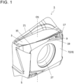
FIG. 1 is a perspective view illustrating a cutting insert in a non-limiting embodiment of the present disclosure; -
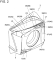
FIG. 2 is a perspective view identical to that of the cutting insert illustrated inFIG. 1 ; -
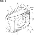
FIG. 3 is a perspective view identical to that of the cutting insert illustrated inFIG. 1 ; -
FIG. 4 is a top view of the cutting insert illustrated inFIG. 1 as viewed from above; -
FIG. 5 is a bottom view of the cutting insert illustrated inFIG. 1 as viewed from below; -
FIG. 6 is a side view of the cutting insert illustrated inFIG. 4 as viewed from A1 direction; -
FIG. 7 is a side view of the cutting insert illustrated inFIG. 4 as viewed from A2 direction; -
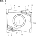
FIG. 8 is a side view of the cutting insert illustrated inFIG. 4 as viewed from A3 direction; -
FIG. 9 is a side view identical to that of the cutting insert illustrated inFIG. 7 ; -
FIG. 10 is a cross-sectional view of the cutting insert illustrated inFIG. 9 , taken along line X-X; -
FIG. 11 is a cross-sectional view of the cutting insert illustrated inFIG. 9 , taken along line XI-XI; -
FIG. 12 is a cross-sectional view of the cutting insert illustrated inFIG. 9 , taken along line XII-XII; -
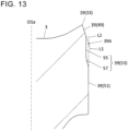
FIG. 13 is an enlarged view of a region B1 illustrated inFIG. 12 ; -
FIG. 14 is a cross-sectional view of the cutting insert illustrated inFIG. 9 , taken along line XIV-XIV; -
FIG. 15 is a cross-sectional view of the cutting insert illustrated inFIG. 9 , taken along line XV-XV; -
FIG. 16 is an enlarged view of a region B2 illustrated inFIG. 15 ; -
FIG. 17 is a perspective view illustrating a cutting tool in a non-limiting embodiment of the present disclosure; -
FIG. 18 is a side view of the cutting tool illustrated inFIG. 17 ; -
FIG. 19 is an enlarged view of a region B3 illustrated inFIG. 17 ; -
FIG. 20 is a schematic diagram illustrating one of steps in a method for manufacturing a machined product in a non-limiting embodiment of the present disclosure; -
FIG. 21 is a schematic diagram illustrating one of the steps in the method for manufacturing a machined product in the non-limiting embodiment of the present disclosure; and -
FIG. 22 is a schematic diagram illustrating one of the steps in the method for manufacturing a machined product in the non-limiting embodiment of the present disclosure. - A cutting insert 1 (hereinafter also referred to as "
insert 1") in a non-limiting embodiment of the present disclosure is described in detail below with reference to the drawings. For the convenience of description, the drawings referred to in the following illustrate, in simplified form, only main members necessary for describing the embodiment. Theinsert 1 may therefore include any arbitrary structural member not illustrated in the drawings referred to. Dimensions of the members in each of the drawings faithfully represent neither dimensions of actual structural members nor dimensional ratios of these members. - The
insert 1 may include anupper surface 3, alower surface 5, alateral surface 7, and anupper cutting edge 9 as in the non-limiting embodiment illustrated inFIGs. 1 to 16 . The terms "theupper surface 3" and "thelower surface 5" as used herein are used for the sake of convenience and do not respectively indicate upper and lower directions. For example, theupper surface 3 need not be directed upward when using theinsert 1. These points are also true for other parts including the term "upper" or "lower." - The
upper surface 3 may have a polygonal shape. Thelower surface 5 may be located on a side opposite to theupper surface 3. Similarly to theupper surface 3, thelower surface 5 may have a polygonal shape. Theinsert 1 may have a polygonal plate shape. - Examples of the polygonal shape may include triangle, square, pentagon, hexagon, and octagon. For example, the
upper surface 3 may have a rectangular shape as in the non-limiting embodiment illustrated inFIG. 1 . The term "polygonal shape" as used herein need not be a strict polygonal shape. For example, a plurality of sides on theupper surface 3 need not be individually a strict straight line, but may be slightly curved in a front view (top view) of theupper surface 3. - Corners of the
upper surface 3, which are respectively located between adjacent sides, need not be a strict corner. In other words, a plurality of corners on theupper surface 3 need not be a strict corner. These corners may have a convex curvilinear shape as viewed from above, or a combined shape made up of a straight line and a curved line as viewed microscopically. Even if the corners include a part having the convex curvilinear shape and the sides are slightly curved, their respective radii of curvature are completely different from each other, and theupper surface 3 can be macroscopically evaluated as an approximately polygonal shape. The radius of curvature of the sides is set to be 100 times or more a radius of curvature of the corner in the embodiment illustrated inFIG. 4 . These points are also true for thelower surface 5. - An imaginary straight line passing through a center of the
upper surface 3 and a center of thelower surface 5 may be a central axis O1 of theinsert 1. If theupper surface 3 has a polygonal shape, corners located at opposite corners on theupper surface 3 may be individually connected by a straight line, and a point of intersection of these straight lines may be the center of theupper surface 3. A starting point of a diagonal line may be a portion where extension lines of the individual sides constituting the polygonal shape intersect with each other. A centroid position of theupper surface 3 as viewed from above may be the center of theupper surface 3. The center of thelower surface 5 may be defined similarly to the center of theupper surface 3. - The
upper surface 3 may have 180° rotational symmetry around the central axis O1 as viewed from above. Thelower surface 5 may have 180° rotational symmetry around the central axis O1 if thelower surface 5 is viewed from the front (from below). - The
lower surface 5 may include aplanar region 11 located at a midportion of thelower surface 5 as in the non-limiting embodiment illustrated inFIG. 5 . Theplanar region 11 is servable as a seating surface. That is, theplanar region 11 is abuttable against (contactable with) a holder when attaching theinsert 1 to the holder in the case of manufacturing a machined product by using theupper cutting edge 9. - The
planar region 11 may be a flat surface region. The term "flat" as used herein need not be a strict flat. Theplanar region 11 may be approximately flat, and may be slightly curved or may have slight unevenness to such a degree that cannot be seen if theinsert 1 is viewed as a whole. For example, theplanar region 11 may include slight unevenness of approximately several tens of pm. - The
planar region 11 may be located so as to include the central axis O1. Theplanar region 11 may be orthogonal to the central axis O1. The term "being orthogonal" is not limited to being strictly orthogonal, but may denote that a range of approximately 90±5° is permissible. - The
insert 1 is not limited to having a specific size. For example, a maximum width of theinsert 1 if theupper surface 3 is viewed from above may be set to approximately 4-25 mm. A height from theupper surface 3 to thelower surface 5 may be set to approximately 5-20 mm. The term "the height from theupper surface 3 to thelower surface 5" as used herein may denote a maximum value of a distance between theupper surface 3 and thelower surface 5 in a direction parallel to the central axis O1. The height from theupper surface 3 to thelower surface 5 may be rephrased as a width of thelateral surface 7 in a direction along the central axis O1. - The
lateral surface 7 may be located between theupper surface 3 and thelower surface 5. Thelateral surface 7 may connect to theupper surface 3 and thelower surface 5 as in the non-limiting embodiment illustrated inFIGs. 7 and8 . - The
upper cutting edge 9 may be located on an intersection of theupper surface 3 and thelateral surface 7. Theupper cutting edge 9 is usable for machining a workpiece when manufacturing a machined product by using theinsert 1. - The
upper cutting edge 9 may be located on the whole or a part of the intersection of theupper surface 3 and thelateral surface 7. Theupper cutting edge 9 may be located on at least thefirst side 19 as in the non-limiting embodiment illustrated inFIG. 1 , etc. Theupper cutting edge 9 may have a straight line shape or a curvilinear shape if thelateral surface 7 is viewed from the front (the side). Alternatively, theupper cutting edge 9 may have a combined shape made up of a straight line and a curved line as viewed from the side. - If the
insert 1 includes theupper cutting edge 9, one of theupper surface 3 and thelateral surface 7 may include a rake surface region, and the other of theupper surface 3 and thelateral surface 7 may include a flank surface region. Theupper surface 3 may include the rake surface region, and thelateral surface 7 may include the flank surface region as in the non-limiting embodiment illustrated inFIG. 1 . - The
insert 1 may include alower cutting edge 13. Thelower cutting edge 13 may be located on an intersection of thelower surface 5 and thelateral surface 7. Similarly to theupper cutting edge 9, thelower cutting edge 13 is usable for machining the workpiece when manufacturing the machined produced by using theinsert 1. - The
lower cutting edge 13 may be located on the whole or a part of the intersection of thelower surface 5 and thelateral surface 7. Thelower cutting edge 13 may have a straight line shape or a curvilinear shape as viewed from the side. Thelower cutting edge 13 may have a combined shape made up of a straight line and a curved line as viewed from the side. If theinsert 1 includes theupper cutting edge 9 and thelower cutting edge 13, theinsert 1 is servable as a double-sided insert. - The plurality of corners on the
upper surface 3 may include afirst corner 15 and asecond corner 17. The plurality of sides on theupper surface 3 may include afirst side 19. The plurality of sides on theupper surface 3 may further include asecond side 21 in addition to thefirst side 19. That is, theupper surface 3 may include thefirst corner 15, thesecond corner 17, thefirst side 19, and thesecond side 21. - The
first side 19 may connect to thefirst corner 15 and thesecond corner 17, and may be inclined so as to be closer to thelower surface 5 as going from anend portion 19a being connected to thefirst corner 15 to anend portion 19b being connected to thesecond corner 17 as in the non-limiting embodiment illustrated inFIG. 7 . Thesecond side 21 may be located on a side opposite to thefirst side 19. Thesecond side 21 may be located on a side opposite to thefirst side 19 on the basis of the central axis O1. - The
first side 19 and thesecond side 21 may be identical or different in length. Thefirst side 19 and thesecond side 21 may be identical in length as in the non-limiting embodiment illustrated inFIG. 1 . Each of thefirst side 19 and thesecond side 21 may be one of long sides on theupper surface 3 having the rectangular shape. - The
lateral surface 7 may include a firstlateral surface 23. The firstlateral surface 23 may connect to thefirst side 19. Thelateral surface 7 may further include a secondlateral surface 25 in addition to the firstlateral surface 23. The secondlateral surface 25 may connect to thesecond side 21. - The
insert 1 may include a throughhole 27 that opens into the firstlateral surface 23 and the secondlateral surface 25. The throughhole 27 is usable for inserting, for example, a screw when fixing theinsert 1 to the holder. Instead of the screw, for example, a clamping member may be used to fix theinsert 1 to the holder. - The through
hole 27 may open into a center of the firstlateral surface 23 and a center of the secondlateral surface 25. The center of the firstlateral surface 23 and the center of the secondlateral surface 25 may be defined similarly to the center of theupper surface 3. An imaginary straight line passing through the center of the firstlateral surface 23 and the center of the secondlateral surface 25 may be a central axis O2 of the throughhole 27. The central axis O2 of the throughhole 27 may be orthogonal to the central axis O1 of theinsert 1. The throughhole 27 is not limited to having such configuration as to open into the firstlateral surface 23 and the secondlateral surface 25. The throughhole 27 may open into, for example, theupper surface 3 and thelower surface 5. - The
first side 19 may include afirst part 29, asecond part 31, and athird part 33 as in the non-limiting embodiment illustrated inFIG. 2 . Thefirst part 29 may connect to thefirst corner 15. Thesecond part 31 may connect to thesecond corner 17. Thethird part 33 may be located between thefirst part 29 and thesecond part 31. Theupper cutting edge 9 may be located at each of thefirst part 29, thesecond part 31, and thethird part 33. - The first
lateral surface 23 may also include afirst region 35, asecond region 37, and athird region 39. Thefirst region 35 may connect to thefirst part 29. Thesecond region 37 may connect to thesecond part 31. Thethird region 39 may connect to thethird part 33. - The
first region 35 may include a firstupper region 41 and a firstlower region 43. As in the non-limiting embodiment illustrated inFIG. 10 , the firstupper region 41 may connect to thefirst part 29 and may be inclined outward as going away from thefirst part 29 in a cross section orthogonal to thefirst side 19 as viewed from above. The term "outward" as used herein may mean a direction away from the central axis O1. - The first
lower region 43 may connect to the firstupper region 41 and may be parallel to the central axis O1 in the above-mentioned cross section. The term "parallel" as used herein is not limited to strict parallel, but may mean an allowance of an inclination of approximately ±0.5°. - The
second region 37 may include a secondupper region 45 and a secondlower region 47 as in the non-limiting embodiment illustrated inFIG. 2 . As in the non-limiting embodiment illustrated inFIGs. 15 and16 , the secondupper region 45 may connect to thesecond part 31 and may be inclined inward as going away from thesecond part 31 in a cross section orthogonal to thefirst side 19 as viewed from above. The term "inward" as used herein may mean a direction toward the central axis O1. - The second
lower region 47 may be located closer to thelower surface 5 than the secondupper region 45, and may be parallel to the central axis O1 in the above-mentioned cross section. A positional relationship with the central axis O1 may be evaluated with reference to an imaginary straight line O1a parallel to the central axis O1 as in the non-limiting embodiment illustrated inFIG. 16 . - The
third region 39 may include a thirdupper region 49, a thirdlower region 51, and aconcave part 53 as in the non-limiting embodiment illustrated inFIG. 2 . As in a non-limiting embodiment illustrated inFIGs. 12 and13 , the thirdupper region 49 may connect to thethird part 33 and may be inclined outward as going away from thethird part 33 in a cross section orthogonal to thefirst side 19 as viewed from above. - The third
lower region 51 may be located closer to thelower surface 5 than the thirdupper region 49, and may be located more outside than the thirdupper region 49 and may be parallel to the central axis O1 in the above-mentioned cross section. - The
concave part 53 may be located between the thirdupper region 49 and the thirdlower region 51, and may be recessed inward from an intersection (intersection point 39A) of an imaginary extension line L1 of the thirdupper region 49 and an imaginary extension line L2 of the thirdlower region 51. - If the
first side 19 is inclined so as to be closer to thelower surface 5 as going from thefirst corner 15 toward thesecond corner 17 as in the non-limiting embodiment illustrated inFIG. 2 , thefirst part 29 located near thefirst corner 15 tends to be subjected to a relatively higher cutting load than thesecond part 31 located near thesecond corner 17. If thefirst region 35 being connected to thefirst part 29 includes a firstupper region 41 inclined outward as going away from thefirst part 29, and a firstlower region 43 parallel to the central axis O1, and both regions connect to each other, thefirst part 29 has a large thickness and high strength. Consequently, thefirst part 29 has high durability. - If the
second region 37 being connected to thesecond part 31 that tends to be subjected to a relatively low cutting load includes a secondupper region 45 inclined inward as going away from thesecond part 31, and a secondlower region 47 parallel to the central axis O1, thesecond region 37 is less liable to interfere with a machining surface of a workpiece. Consequently, the machining surface is less liable to be roughened, thus leading to high surface accuracy. - The
third part 33 located between thefirst part 29 and thesecond part 31 is susceptible to a relatively medium cutting load. If thethird region 39 being connected to thethird part 33 includes sequentially the thirdupper region 49 inclined outward as going away from thethird part 33, theconcave part 53, and the thirdlower region 51 that is located more outside than the thirdupper region 49 and is parallel to the central axis O1, thethird region 39 is much less liable to interfere with the machining surface of the workpiece than thefirst region 35, and tends to have higher durability than thesecond region 37. Thus, theinsert 1 has high durability and achieves high surface accuracy of the machined surface. - The above-mentioned cross section in the first
upper region 41 and the firstlower region 43 may be rephrased as a first cross section that is orthogonal to thefirst part 29 and includes thefirst region 35 as viewed from above. The above-mentioned cross section in the secondupper region 45 and the secondlower region 47 may be rephrased as a second cross section that is orthogonal to thesecond part 31 and includes thesecond region 37 as viewed from above. The above-mentioned cross section in the thirdupper region 49, the thirdlower region 51, and theconcave part 53 may be rephrased as a third cross section that is orthogonal to thethird part 33 and includes thethird region 39 as viewed from above. - The
concave part 53 may include a firstpartial region 55 and a secondpartial region 57 as in the non-limiting embodiment illustrated inFIG. 3 . The firstpartial region 55 may connect to the thirdupper region 49 and may be parallel to the central axis O1 in the above-mentioned cross section (third cross section) as in the non-limiting embodiment illustrated inFIG. 13 . The secondpartial region 57 may connect to the thirdlower region 51 and the firstpartial region 55, and may be inclined outward as going away from the firstpartial region 55 in the above cross section. In these cases, a part located at thethird part 33 in theupper cutting edge 9 has enhanced durability, thus leading to high durability of theinsert 1. - A width W1 in a direction along the central axis O1 in the first
partial region 55 may be constant or changed. For example, the width W1 may increase as coming closer to thesecond corner 17 as in the non-limiting embodiment illustrated inFIG. 3 . With this configuration, the secondpartial region 57 and the thirdlower region 51 are less liable to interfere with a machining surface of a workpiece. In cases where the throughhole 27 is located below theconcave part 53 and theconcave part 53 is located closer to thesecond corner 17 than a center (central axis O2) of the throughhole 27 as in the non-limiting embodiment illustrates inFIGs. 1 to 3 andFIG. 7 , it is possible to enhance strength of theinsert 1 around the throughhole 27. Therefore, a crack is less liable to occur around the throughhole 27 when fixing theinsert 1 to the holder. - A width W2 in a direction along the central axis O1 in the second
partial region 57 may be constant or changed. For example, if the width W2 is constant as in the non-limiting embodiment illustrated inFIG. 3 , load exerted on the secondpartial region 57 during machining is less liable to be concentrated at a certain location and tends to be dispersed in a wide range of the secondpartial region 57. - A width W3 in a direction along the central axis O1 in the second
upper region 45 may be constant or changed. For example, the width W3 may increase as coming closer to thesecond corner 17 as in the non-limiting embodiment illustrated inFIG. 3 . With this configuration, the secondlower region 47 is less liable to interfere with a machining surface of a workpiece. - The
concave part 53 may also be located between the secondupper region 45 and the secondlower region 47 as in the non-limiting embodiment illustrated inFIGs. 2 and3 . With this configuration, the secondlower region 47 is less liable to interfere with a machining surface of a workpiece, and a part located at thesecond part 31 in theupper cutting edge 9 has enhanced durability. - The first
lower region 43, the secondlower region 47, and the thirdlower region 51 may be located on an identical plane as in the non-limiting embodiment illustrated inFIG. 2 . The firstlower region 43, the secondlower region 47, and the thirdlower region 51 are servable as a so-called constraining surface when attaching theinsert 1 to the holder. If the firstlower region 43, the secondlower region 47, and the thirdlower region 51 are located on the identical plane, theinsert 1 tends to be stably constrained by the holder if these regions are used as the constraining surface. - An end on a side of the
second corner 17 in thefirst part 29 may be located closer to thesecond corner 17 than the central axis O1 as in the non-limiting embodiment illustrated inFIG. 2 . A length of thefirst part 29 may be larger than each of a length of thesecond part 31 and a length of thethird part 33. The length of thethird part 33 may be larger than the length of thesecond part 31. - The
third part 33 may connect to thefirst part 29 or may be located away from thefirst part 29. Similarly, thethird part 33 may connect to thesecond part 31 or may be located away from thesecond part 31. For example, thethird part 33 may connect to each of thefirst part 29 and thesecond part 31 as in the non-limiting embodiment illustrated inFIG. 2 . In this case, thethird region 39 may connect to each of thefirst region 35 and thesecond region 37. - The second
upper region 45 may be inclined at an inclination angle θ1 as in the non-limiting embodiment illustrated inFIG. 16 . The inclination angle θ1 may be evaluated by an angle with respect to the central axis O1 (imaginary straight line O1a). The inclination angle θ1 is not limited to a specific value. For example, the inclination angle θ1 may be set to 1-5°. - The second
upper region 45 may be located between the thirdupper region 49 and theconcave part 53 as in the non-limiting embodiment illustrated inFIG. 14 . - For example, cemented carbide and cermet are usable as a material of the
insert 1. Examples of composition of the cemented carbide may include WC-Co, WC-TiC-Co, and WC-TiC-TaC-Co, in which WC, TiC and TaC may be hard particles and Co may be a binding phase. - The cermet may be a sintered composite material obtainable by compositing metal into a ceramic component. Examples of the cermet may include titanium compounds composed mainly of titanium carbide (TiC) or titanium nitride (TiN). Of course, it should be clear that the material of the
insert 1 is not limited to the above compositions. - A surface of the
insert 1 may be coated with a coating film by using chemical vapor deposition (CVD) method or physical vapor deposition (PVD) method. Examples of composition of the coating film may include titanium carbide (TiC), titanium nitride (TiN), titanium carbon nitride (TiCN), and alumina (Al2O3). - A
cutting tool 101 in a non-limiting embodiment of the present disclosure is described below with reference toFIGs. 17 to 19 . As in the non-limiting embodiment illustrated inFIG. 17 , etc., a rotation axis O3 of thecutting tool 101 may be indicated by a two-dot chain line, and a rotation direction of the rotation axis O3 may be indicated by an arrow Y1. - The
cutting tool 101 may include aholder 103 and aninsert 1 as in the non-limiting embodiment illustrated inFIGs. 17 to 19 . If thecutting tool 101 includes theinsert 1, excellent cutting performance is attainable because of high durability of theinsert 1 and high surface accuracy of a machined surface. - The
cutting tool 101 is rotatable around therotation axis 03. Thecutting tool 101 may be used for a milling process. - The
holder 103 may have a columnar shape extending along the rotation axis O3 from afirst end 103a to asecond end 103b. The columnar shape may be an approximately columnar shape, and need not be a strict columnar shape. - The
holder 103 may include apocket 105 located on a side of thefirst end 103a. Theinsert 1 is attachable to thepocket 105. Thepocket 105 may open into an outer peripheral surface of theholder 103 and an end surface on a side of thefirst end 103a. - The
insert 1 may be located in thepocket 105. There may be one or a plurality ofpockets 105. If theholder 103 includes the plurality ofpockets 105, thecutting tool 101 may include a plurality ofinserts 1, and theinserts 1 may be located one by one in thepockets 105. - In cases where the
holder 103 includes the plurality ofpockets 105, thesepockets 105 may be located around the rotation axis O3 at equal intervals or unequal intervals. - The
insert 1 may be fitted to thepocket 105 so that at least a part of the cutting edge can protrude from theholder 103. For example, theinsert 1 may be attached to theholder 103 so that theupper cutting edge 9 can protrude from theholder 103 toward a workpiece. In this case, thelower surface 5 and thelateral surface 7 may be in contact with theholder 103. - The
insert 1 may be attached to theholder 103 so that thefirst corner 15 can be located closer to thefirst end 103a than thesecond corner 17, and so that thefirst side 19 can be located closer to an outer periphery side than thesecond side 21. - The
insert 1 may be fitted into thepocket 105 with ascrew 107. Specifically, theinsert 1 may be attached to theholder 103 by inserting thescrew 107 into the throughhole 27 of theinsert 1, and by inserting a front end of thescrew 107 into a screw hole formed in thepocket 105 so as to fix thescrew 107 to the screw hole. - For example, steel and cast iron are usable as a material of the
holder 103. If the material of theholder 103 is steel, theholder 103 has high toughness. - A method for manufacturing a
machined product 201 in a non-limiting embodiment of the present disclosure is described below with reference toFIGs. 20 to 22 . - The
machined product 201 may be manufactured by carrying out a machining process of aworkpiece 203. The method for manufacturing the machinedproduct 201 may include the following steps: - (1) rotating the
cutting tool 101 represented by the above non-limiting embodiment; - (2) bringing the
cutting tool 101 being rotated into contact with theworkpiece 203; and - (3) moving the
cutting tool 101 away from theworkpiece 203. - Specifically, firstly, the
cutting tool 101 may be relatively brought near theworkpiece 203 while rotating thecutting tool 101 around the rotation axis O3 in a Y1 direction as in the non-limiting embodiment illustrated inFIG. 20 . Subsequently, theworkpiece 203 may be cut out by bringing theupper cutting edge 9 of thecutting tool 101 into contact with theworkpiece 203 as in the non-limiting embodiment illustrated inFIG. 21 . Thereafter, thecutting tool 101 may be relatively moved away from theworkpiece 203 as in the non-limiting embodiment illustrated inFIG. 22 . - The
machined product 201 having a highly precise machined surface is obtainable by going through the foregoing steps. - Although the
workpiece 203 is fixed and thecutting tool 101 is moved in the individual steps in the non-limiting embodiment illustrated inFIGs. 20 to 22 , there is, of course, no intention to limit to this embodiment. - For example, the
workpiece 203 may be brought near thecutting tool 101 in the step (1). Similarly, theworkpiece 203 may be moved away from thecutting tool 101 in the step (3). If it is desired to continue the machining process, the step of bringing theupper cutting edge 9 of theinsert 1 into contact with different portions of theworkpiece 203 may be repeated while keeping thecutting tool 101 rotated. - Examples of material of the
workpiece 203 may include carbon steel, alloy steel, stainless steel, cast iron, and nonferrous metals. -
- 1
- cutting insert (insert)
- 3
- upper surface
- 5
- lower surface
- 7
- lateral surface
- 9
- upper cutting edge
- 11
- planar region
- 13
- lower cutting edge
- 15
- first corner
- 17
- second corner
- 19
- first side
- 19a
- end part
- 19b
- end part
- 21
- second side
- 23
- first lateral surface
- 25
- second lateral surface
- 27
- through hole
- 29
- first part
- 31
- second part
- 33
- third part
- 35
- first region
- 37
- second region
- 39
- third region
- 41
- first upper region
- 43
- first lower region
- 45
- second upper region
- 47
- second lower region
- 49
- third upper region
- 51
- third lower region
- 53
- concave part
- 55
- first partial region
- 57
- second partial region
- 101
- cutting tool
- 103
- holder
- 103a
- first end
- 103b
- second end
- 105
- 107
- screw
- 201
- machined product
- 203
- workpiece
- O1
- central axis of cutting insert
- O2
- central axis of through hole
- O3
- rotation axis
Claims (9)
- A cutting insert, comprising:an upper surface having a polygonal shape;a lower surface located on a side opposite to the upper surface;a lateral surface located between the upper surface and the lower surface; andan upper cutting edge located on an intersection of the upper surface and the lateral surface, whereinan imaginary straight line passing through a center of the upper surface and a center of the lower surface is a central axis,the upper surface comprisesa first corner,a second corner, anda first side that is connected to the first corner and the second corner and is inclined so as be closer to the lower surface as going from an end part being connected to the first corner toward an end part being connected to the second corner,the lateral surface comprises a first lateral surface being connected to the first side,the first side comprisesa first part being connected to the first corner,a second part being connected to the second corner, anda third part located between the first part and the second part,the first lateral surface comprisesa first region being connected to the first part,a second region being connected to the second part, anda third region being connected to the third part,the first region comprises, in a cross section orthogonal to the first side as viewed from above,a first upper region that is connected to the first part and is inclined outward as going away from the first part, anda first lower region that is connected to the first upper region and is parallel to the central axis,the second region comprises, in a cross section orthogonal to the first side as viewed from above,a second upper region that is connected to the second part and is inclined inward as going away from the second part, anda second lower region that is located closer to the lower surface than the second upper region and is parallel to the central axis, andthe third region comprises, in a cross section orthogonal to the first side as viewed from above,a third upper region that is connected to the third part and is inclined outward as going away from the third part,a third lower region that is located closer to the lower surface than the third upper region and is located more outside than the third upper region and is parallel to the central axis, anda concave part that is located between the third upper region and the third lower region and is recessed inward from an intersection of an imaginary extension line of the third upper region and an imaginary extension line of the third lower region.
- The cutting insert according to claim 1, wherein
the concave part comprisesa first partial region that is connected to the third upper region and is parallel to the central axis, anda second partial region that is connected to the third lower region and the first partial region and is inclined outward as going away from the first partial region. - The cutting insert according to claim 2, wherein a width in a direction along the central axis in the first partial region increases as coming closer to the second corner.
- The cutting insert according to claim 2 or 3, wherein a width in a direction along the central axis in the second partial region is constant.
- The cutting insert according to any one of claims 1 to 4, wherein a width in a direction along the central axis in the second upper region increases as coming closer to the second corner.
- The cutting insert according to any one of claims 1 to 5, wherein the concave part is also located between the second upper region and the second region.
- The cutting insert according to any one of claims 1 to 6, wherein the first lower region, the second lower region, and the third lower region are located on an identical plane.
- A cutting tool, comprising:a holder having a columnar shape extending along a rotation axis from a first end to a second end, the holder comprising a pocket located on a side of the first end; andthe cutting insert according to any one of claims 1 to 7, the cutting insert being located in the pocket.
- A method for manufacturing a machined product, comprising:rotating the cutting tool according to claim 8;bringing the cutting tool being rotated into contact with a workpiece; andmoving the cutting tool away from the workpiece.
Applications Claiming Priority (2)
| Application Number | Priority Date | Filing Date | Title |
|---|---|---|---|
| JP2021166753 | 2021-10-11 | ||
| PCT/JP2022/037260 WO2023063184A1 (en) | 2021-10-11 | 2022-10-05 | Cutting insert, cutting tool, and method for manufacturing cut product |
Publications (2)
| Publication Number | Publication Date |
|---|---|
| EP4417350A1 true EP4417350A1 (en) | 2024-08-21 |
| EP4417350A4 EP4417350A4 (en) | 2025-09-17 |
Family
ID=85988617
Family Applications (1)
| Application Number | Title | Priority Date | Filing Date |
|---|---|---|---|
| EP22880880.4A Pending EP4417350A4 (en) | 2021-10-11 | 2022-10-05 | CUTTING INSERT, CUTTING TOOL AND METHOD FOR PRODUCING A CUTTING PRODUCT |
Country Status (6)
| Country | Link |
|---|---|
| US (1) | US20240408681A1 (en) |
| EP (1) | EP4417350A4 (en) |
| JP (1) | JP7573759B2 (en) |
| KR (1) | KR102835316B1 (en) |
| CN (1) | CN117999139A (en) |
| WO (1) | WO2023063184A1 (en) |
Families Citing this family (1)
| Publication number | Priority date | Publication date | Assignee | Title |
|---|---|---|---|---|
| JP7778293B1 (en) * | 2025-03-24 | 2025-12-02 | 株式会社タンガロイ | Cutting inserts and rotary cutting tools |
Family Cites Families (23)
| Publication number | Priority date | Publication date | Assignee | Title |
|---|---|---|---|---|
| GB9010769D0 (en) * | 1990-05-14 | 1990-07-04 | Iscar Hartmetall | Cutting insert |
| US6802676B2 (en) * | 2001-03-02 | 2004-10-12 | Valenite Llc | Milling insert |
| IL158098A (en) * | 2003-09-24 | 2008-03-20 | Amir Satran | Tangential cutting insert and milling cutter |
| IL160223A (en) * | 2004-02-04 | 2008-11-26 | Carol Smilovici | Double-sided cutting insert and milling cutter |
| US7104735B2 (en) | 2004-09-02 | 2006-09-12 | Ingersoll Cutting Tool Company | Tangential cutting insert and milling cutter |
| JP4491404B2 (en) | 2005-11-07 | 2010-06-30 | 住友電工ハードメタル株式会社 | Tip changeable insert and tip changeable corner milling cutter |
| SE531250C2 (en) * | 2007-06-05 | 2009-02-03 | Sandvik Intellectual Property | Indexable corner cutter |
| IL187721A (en) * | 2007-11-28 | 2014-05-28 | Iscar Ltd | Cutting put |
| IL203283A (en) * | 2010-01-13 | 2014-02-27 | Iscar Ltd | Cutting insert |
| CN102958634B (en) * | 2010-10-05 | 2015-08-26 | 京瓷株式会社 | Cutting insert and cutting element and use the manufacture method of machining thing of this cutting element |
| JP5906976B2 (en) * | 2011-10-04 | 2016-04-20 | 三菱マテリアル株式会社 | Cutting insert and cutting edge changeable cutting tool |
| CN107297531B (en) * | 2011-10-31 | 2019-11-22 | 京瓷株式会社 | Cutting Insert |
| JP6127343B2 (en) * | 2013-03-26 | 2017-05-17 | 住友電工ハードメタル株式会社 | Cutting insert for milling cutter |
| EP2893995B1 (en) * | 2014-01-08 | 2019-03-27 | Sandvik Intellectual Property AB | A metal cutting insert and a milling tool |
| EP3199282B1 (en) * | 2014-09-26 | 2020-07-29 | KYOCERA Corporation | Cutting insert, cutting tool, and method for producing cut article |
| US10046398B2 (en) * | 2014-12-15 | 2018-08-14 | Seco Tools Ab | Reinforced double-sided cutting insert and cutting tool with reinforced double-sided cutting insert |
| EP3072616B1 (en) * | 2015-03-25 | 2018-10-10 | Sandvik Intellectual Property AB | Cutting insert and milling tool |
| JP6853442B2 (en) * | 2015-09-15 | 2021-03-31 | 三菱マテリアル株式会社 | Cutting inserts and cutting tools with replaceable cutting edges |
| EP3556498B1 (en) * | 2018-04-16 | 2021-02-17 | Seco Tools Ab | Cutting insert and milling tool |
| JP7035176B2 (en) * | 2018-05-07 | 2022-03-14 | 京セラ株式会社 | Manufacturing method of cutting inserts, cutting tools and cutting materials |
| JP2021166753A (en) | 2020-03-24 | 2021-10-21 | 株式会社三洋物産 | Game machine |
| US11583942B2 (en) * | 2020-10-19 | 2023-02-21 | Iscar, Ltd. | Reversible square-shaped cutting insert and rotary cutting tool |
| US20240326140A1 (en) * | 2023-03-28 | 2024-10-03 | Kennametal Inc. | Double-sided, indexable cutting insert with high ramping capability and cutting tool therefor |
-
2022
- 2022-10-05 WO PCT/JP2022/037260 patent/WO2023063184A1/en not_active Ceased
- 2022-10-05 KR KR1020247007538A patent/KR102835316B1/en active Active
- 2022-10-05 CN CN202280063067.2A patent/CN117999139A/en active Pending
- 2022-10-05 JP JP2023554439A patent/JP7573759B2/en active Active
- 2022-10-05 EP EP22880880.4A patent/EP4417350A4/en active Pending
- 2022-10-05 US US18/697,478 patent/US20240408681A1/en active Pending
Also Published As
| Publication number | Publication date |
|---|---|
| JP7573759B2 (en) | 2024-10-25 |
| KR102835316B1 (en) | 2025-07-17 |
| JPWO2023063184A1 (en) | 2023-04-20 |
| US20240408681A1 (en) | 2024-12-12 |
| EP4417350A4 (en) | 2025-09-17 |
| KR20240038106A (en) | 2024-03-22 |
| CN117999139A (en) | 2024-05-07 |
| WO2023063184A1 (en) | 2023-04-20 |
Similar Documents
| Publication | Publication Date | Title |
|---|---|---|
| US12370610B2 (en) | Cutting insert, cutting tool, and method for manufacturing machined product | |
| US12325078B2 (en) | Cutting insert, cutting tool, and method for manufacturing machined product | |
| CN111050960B (en) | Cutting insert, cutting tool, and manufacturing method of machined product | |
| KR102745530B1 (en) | Rotating tool and method for manufacturing cut workpieces | |
| EP4417350A1 (en) | Cutting insert, cutting tool, and method for manufacturing cut product | |
| US11440103B2 (en) | Cutting insert, cutting tool, and method for manufacturing machined product | |
| JP6810807B2 (en) | Manufacturing method for cutting inserts, cutting tools and cutting products | |
| US12186816B2 (en) | Cutting insert, cutting tool and method for manufacturing machined product | |
| US20200130072A1 (en) | Cutting insert, cutting tool, and method for manufacturing machined product | |
| US10987741B2 (en) | Cutting insert, cutting tool, and method for manufacturing machined product | |
| US12533735B2 (en) | Cutting insert, cutting tool, and method for manufacturing machined product | |
| KR102540681B1 (en) | Methods for manufacturing cutting inserts, cutting tools and cutting components | |
| JPWO2019022016A1 (en) | Manufacturing method of cutting insert, cutting tool, and machined product | |
| US20250196235A1 (en) | Cutting insert, cutting tool, and method for manufacturing machined product | |
| JP7344168B2 (en) | Manufacturing method for cutting inserts, cutting tools, and cut products | |
| US12337391B2 (en) | Cutting insert, cutting tool, and method for manufacturing machined product |
Legal Events
| Date | Code | Title | Description |
|---|---|---|---|
| STAA | Information on the status of an ep patent application or granted ep patent |
Free format text: STATUS: THE INTERNATIONAL PUBLICATION HAS BEEN MADE |
|
| PUAI | Public reference made under article 153(3) epc to a published international application that has entered the european phase |
Free format text: ORIGINAL CODE: 0009012 |
|
| STAA | Information on the status of an ep patent application or granted ep patent |
Free format text: STATUS: REQUEST FOR EXAMINATION WAS MADE |
|
| 17P | Request for examination filed |
Effective date: 20240308 |
|
| AK | Designated contracting states |
Kind code of ref document: A1 Designated state(s): AL AT BE BG CH CY CZ DE DK EE ES FI FR GB GR HR HU IE IS IT LI LT LU LV MC ME MK MT NL NO PL PT RO RS SE SI SK SM TR |
|
| DAV | Request for validation of the european patent (deleted) | ||
| DAX | Request for extension of the european patent (deleted) | ||
| A4 | Supplementary search report drawn up and despatched |
Effective date: 20250820 |
|
| RIC1 | Information provided on ipc code assigned before grant |
Ipc: B23C 5/20 20060101AFI20250813BHEP Ipc: B23C 5/10 20060101ALI20250813BHEP |