EP4417332A1 - Schrott-räumungssystem, metallband-fertigungsstrasse und schrotträumverfahren - Google Patents
Schrott-räumungssystem, metallband-fertigungsstrasse und schrotträumverfahren Download PDFInfo
- Publication number
- EP4417332A1 EP4417332A1 EP23157217.3A EP23157217A EP4417332A1 EP 4417332 A1 EP4417332 A1 EP 4417332A1 EP 23157217 A EP23157217 A EP 23157217A EP 4417332 A1 EP4417332 A1 EP 4417332A1
- Authority
- EP
- European Patent Office
- Prior art keywords
- metal strip
- scrap
- production line
- strip
- transport
- Prior art date
- Legal status (The legal status is an assumption and is not a legal conclusion. Google has not performed a legal analysis and makes no representation as to the accuracy of the status listed.)
- Granted
Links
Images

Classifications
-
- B—PERFORMING OPERATIONS; TRANSPORTING
- B21—MECHANICAL METAL-WORKING WITHOUT ESSENTIALLY REMOVING MATERIAL; PUNCHING METAL
- B21B—ROLLING OF METAL
- B21B15/00—Arrangements for performing additional metal-working operations specially combined with or arranged in, or specially adapted for use in connection with, metal-rolling mills
- B21B15/0007—Cutting or shearing the product
-
- B—PERFORMING OPERATIONS; TRANSPORTING
- B21—MECHANICAL METAL-WORKING WITHOUT ESSENTIALLY REMOVING MATERIAL; PUNCHING METAL
- B21B—ROLLING OF METAL
- B21B1/00—Metal-rolling methods or mills for making semi-finished products of solid or profiled cross-section; Sequence of operations in milling trains; Layout of rolling-mill plant, e.g. grouping of stands; Succession of passes or of sectional pass alternations
- B21B1/22—Metal-rolling methods or mills for making semi-finished products of solid or profiled cross-section; Sequence of operations in milling trains; Layout of rolling-mill plant, e.g. grouping of stands; Succession of passes or of sectional pass alternations for rolling plates, strips, bands or sheets of indefinite length
-
- B—PERFORMING OPERATIONS; TRANSPORTING
- B21—MECHANICAL METAL-WORKING WITHOUT ESSENTIALLY REMOVING MATERIAL; PUNCHING METAL
- B21B—ROLLING OF METAL
- B21B1/00—Metal-rolling methods or mills for making semi-finished products of solid or profiled cross-section; Sequence of operations in milling trains; Layout of rolling-mill plant, e.g. grouping of stands; Succession of passes or of sectional pass alternations
- B21B1/46—Metal-rolling methods or mills for making semi-finished products of solid or profiled cross-section; Sequence of operations in milling trains; Layout of rolling-mill plant, e.g. grouping of stands; Succession of passes or of sectional pass alternations for rolling metal immediately subsequent to continuous casting
- B21B1/463—Metal-rolling methods or mills for making semi-finished products of solid or profiled cross-section; Sequence of operations in milling trains; Layout of rolling-mill plant, e.g. grouping of stands; Succession of passes or of sectional pass alternations for rolling metal immediately subsequent to continuous casting in a continuous process, i.e. the cast not being cut before rolling
-
- B—PERFORMING OPERATIONS; TRANSPORTING
- B21—MECHANICAL METAL-WORKING WITHOUT ESSENTIALLY REMOVING MATERIAL; PUNCHING METAL
- B21B—ROLLING OF METAL
- B21B15/00—Arrangements for performing additional metal-working operations specially combined with or arranged in, or specially adapted for use in connection with, metal-rolling mills
- B21B15/0007—Cutting or shearing the product
- B21B2015/0014—Cutting or shearing the product transversely to the rolling direction
-
- B—PERFORMING OPERATIONS; TRANSPORTING
- B21—MECHANICAL METAL-WORKING WITHOUT ESSENTIALLY REMOVING MATERIAL; PUNCHING METAL
- B21B—ROLLING OF METAL
- B21B15/00—Arrangements for performing additional metal-working operations specially combined with or arranged in, or specially adapted for use in connection with, metal-rolling mills
- B21B2015/0057—Coiling the rolled product
-
- B—PERFORMING OPERATIONS; TRANSPORTING
- B21—MECHANICAL METAL-WORKING WITHOUT ESSENTIALLY REMOVING MATERIAL; PUNCHING METAL
- B21C—MANUFACTURE OF METAL SHEETS, WIRE, RODS, TUBES, PROFILES OR LIKE SEMI-MANUFACTURED PRODUCTS OTHERWISE THAN BY ROLLING; AUXILIARY OPERATIONS USED IN CONNECTION WITH METAL-WORKING WITHOUT ESSENTIALLY REMOVING MATERIAL
- B21C47/00—Winding-up, coiling or winding-off metal wire, metal band or other flexible metal material characterised by features relevant to metal processing only
- B21C47/26—Special arrangements with regard to simultaneous or subsequent treatment of the material
- B21C47/267—Scrap treatment
-
- B—PERFORMING OPERATIONS; TRANSPORTING
- B21—MECHANICAL METAL-WORKING WITHOUT ESSENTIALLY REMOVING MATERIAL; PUNCHING METAL
- B21C—MANUFACTURE OF METAL SHEETS, WIRE, RODS, TUBES, PROFILES OR LIKE SEMI-MANUFACTURED PRODUCTS OTHERWISE THAN BY ROLLING; AUXILIARY OPERATIONS USED IN CONNECTION WITH METAL-WORKING WITHOUT ESSENTIALLY REMOVING MATERIAL
- B21C47/00—Winding-up, coiling or winding-off metal wire, metal band or other flexible metal material characterised by features relevant to metal processing only
- B21C47/34—Feeding or guiding devices not specially adapted to a particular type of apparatus
- B21C47/3433—Feeding or guiding devices not specially adapted to a particular type of apparatus for guiding the leading end of the material, e.g. from or to a coiler
Definitions
- the present invention relates to a scrap removal system for a metal strip production line, in particular a casting-rolling composite plant, a metal strip production line with such a scrap removal system and a method for removing scrap from a metal strip production line.
- metal strip production lines in particular cast-rolling composite plants for endless strip production (endless strip production plant), (continuously) cast strands or slabs made from them are rolled into strips using a rolling mill. At the end of each production line, the rolled strip can then be wound up by a reel. Once the metal coil created during winding has reached a predetermined size or the wound strip has reached a predetermined length, the strip is cut in the transport direction in front of the reel using a traveling strip shear that follows the speed of the strip, such as a drum shear or the like. Winding of a new metal coil can then begin. To enable continuous production, additional reels are usually provided to which the rolled strip can be selectively fed.
- problems can arise due to the failure of components on the production line or when threading the strip into the reel due to the high elasticity or flexibility compared to thicker strips and the high conveying speed.
- a so-called "cobble" can form, i.e. a strong deformation of the strip in a strip section, which prevents the strip from being conveyed further.
- the operation of the production line or cast-rolling composite plant must be interrupted and the affected section of the strip removed. This requires manually cutting the strip, for example by means of several flame cuts, and lifting the strip out of the production line, for example using an overhead crane. Such a procedure is usually very complex due to the length of the strip section to be removed.
- the strip to be scrapped must be removed over a length from an induction furnace entrance in front of a finishing mill to the coiler area and also from a laminar cooling area between the finishing mill and the coiler area. This scrap must then be manually cut into a manageable format and disposed of.
- a scrap removal system for a metal strip production line, in particular a casting-rolling composite plant, according to a first aspect of the invention has a cutting means for cutting a metal strip fed to the scrap removal system and a strip catcher arranged in front of the cutting means in a transport direction of the metal strip.
- the strip catcher has a pivotably mounted catching arm.
- a cutting means in the sense of the present invention is preferably a device that is designed to cut a metal strip.
- the cutting means can cut a metal strip, for example, into a first strip section and a second strip section that follows it in terms of a transport direction.
- the cutting means can be designed, for example, as a strip shear, such as a hydraulically actuated toggle lever shear.
- a strip catcher in the sense of the present invention is preferably a device that is designed to catch or catch a metal strip, in particular an incoming metal strip head end.
- the strip catcher can, for example, prevent the metal strip from being transported uncontrolled or at least unbraked beyond the end of a production line, in particular a combined casting and rolling plant.
- a conventional strip catcher has a collecting basket that blocks the transport path of the metal strip.
- a strip catcher is expediently arranged behind the last reel in the production line in a transport direction.
- One aspect of the invention is based on the approach of providing an arrangement comprising a cutting means for cutting a metal strip and, with respect to a transport direction of the metal strip, upstream of a strip catcher with a pivotable catching arm.
- This arrangement can, for example, be provided downstream of the last reel of a metal strip production line, in particular a combined casting and rolling plant, and expediently forms a scrap clearance system.
- the pivoting catch arm With the help of the pivoting catch arm, a transport path to the cutting device that is blocked during normal operation of the production line can be cleared.
- the cutting device at the end of the production line enables the automatic or at least semi-automatic shredding of a metal strip section to be scrapped, without this metal strip section having to be lifted out of the production line at great expense and subsequently (manually) shredded.
- the scrap clearance system can significantly speed up the removal of a strip section from the production line and thus shorten the plant downtime associated with a loss of production.
- the end-side cutting device can reduce the risk of injuries such as cuts or burns when manually cutting the strip. At the same time, the risk of damaging components of the production line, such as rollers or cooling heads, when carrying out the necessary flame cuts can be reduced.
- the catch arm can be pivoted between a catch position and a release position in a preferred embodiment.
- the catch arm expediently blocks the transport path through the scrap removal system in the catch position.
- the catch arm in the catch position can protrude at least partially into a transport path of the metal strip in such a way that the metal strip is guided by the catch arm out of the transport direction into a catch basket.
- the catch arm in the catch position can therefore reliably prevent the metal strip from being undesirably transported to the cutting means during normal operation of the production line. This can prevent damage to the cutting means and/or uncontrolled escape of the metal strip from the production line at the end.
- a metal strip fed into the scrap removal system can conveniently pass through the strip catcher.
- the catcher arm can, for example, be swung out of the transport path of the metal strip.
- a first transport device for conveying the metal strip past the strip catcher.
- the transport device can be designed as a roller conveyor, for example. , in particular as a roller table with several rollers. At least some of the rollers are expediently actively drivable, ie provided with a drive or coupled.
- the first transport means is preferably an active transport means.
- the first transport means also enables seamless integration of the scrap clearance system into the production line, for example by connecting it to the transport path to the last reel of the production line.
- the first transport means preferably extends over a transport section in the transport direction in front of the strip catcher and a transport section in the transport direction behind the strip catcher, in particular up to the cutting means.
- rollers of the first transport means can be provided both upstream and downstream of the strip catcher.
- the transport means can transport the metal strip from the last reel of the production line to the cutting means or at least past the strip catcher.
- a second transport means is preferably provided for feeding the metal strip into the cutting means, in particular selectively or specifically.
- This second transport means is expediently arranged behind the strip catcher and immediately in front of the cutting means in the transport direction.
- the second conveyor can, for example, have a conveyor roller, also referred to as a driver roller, which is set up to actively transport the metal strip.
- the second conveyor is expediently arranged or can be arranged in such a way that the transport path through the scrap clearance system runs at least partially between the first and second transport means. It is preferred that the metal strip is supported on an underside by the first transport means, for example the roller table, while the second transport means, for example the driver roller, is placed against an upper side of the metal strip with a predetermined pressure.
- a head end, i.e. the front end in the transport direction, of the metal strip or metal strip section to be scrapped can be positioned downstream of the cutting means, for example, in such a way that actuation of the cutting means produces a manageable metal strip or scrap part.
- a container is preferably provided for receiving metal strip sections cut by the cutting means.
- the container is expediently arranged behind the cutting means in the transport direction, for example in such a way that the scrap parts can fall into the container.
- the container also referred to as a scrap bucket, can in particular be a container.
- the metal strip production line in particular the casting-rolling composite plant, according to a second aspect of the invention has a scrap removal system according to the first aspect of the invention.
- the scrap removal system By means of the scrap removal system, the occurrence of cobbles downtimes and the associated production losses on the production line can be reduced.
- the scrap clearance system increases operational reliability, as fewer operating personnel are required to remove a metal strip section from the production line and, in particular, fewer manual work steps, such as flame cutting, have to be carried out. In addition, less indoor crane activity may be required.
- the metal strip production line can, for example, have a roughing line, an induction furnace, a finishing line, a cooling section and one or more reels.
- the scrap removal system is preferably arranged after the last component of the production line in the transport direction of the metal strip through the production line, in particular behind the last reel in the transport direction.
- the scrap removal system can in particular be attached to the production line and thus extend the production line.
- a metal strip located in a metal strip production line is divided into a first metal strip section and a second metal strip section, the first metal strip section being located in front of the second metal strip section in a transport direction through the metal strip production line.
- the first metal strip section can in this sense be understood as a preceding metal strip section and the second metal strip section as a following metal strip section.
- the first metal strip section is removed from the metal strip production line.
- the second metal strip section is conveyed through the metal strip production line to a scrap removal system, in particular arranged downstream of a last reel.
- the second metal strip section is then cut into a large number of metal strip pieces, which can also be referred to as scrap parts, by means of a cutting means of the scrap removal system.
- the cutting of the second metal strip section can be carried out automatically or at least semi-automatically, so that operating personnel can be saved and operational reliability can be increased.
- the metal strip is expediently first divided in such a way that the first metal strip section comprises a cobble, ie an undesirably deformed strip section. Since such a deformation makes further conveyance of the first metal strip section through the production line difficult or even impossible, the first metal strip section is preferably lifted out of the metal strip production line. For example, the first metal strip section can be lifted out of the production line using a crane.
- a catch arm of a strip catcher of the scrap removal system which is arranged upstream of the cutting means in the transport direction, is preferably pivoted from a catch position to a release position before the second metal strip section is conveyed to the scrap removal system.
- the catch arm expediently blocks a transport path through the scrap removal system.
- the catch arm in the catch position can reliably prevent the metal strip from being undesirably conveyed to the cutting means during normal operation of the production line. This can prevent any damage to the cutting means and/or uncontrolled escape of the metal strip from the production line at the end of the line.
- the metal strip fed to the scrap clearance system can conveniently pass through the strip catcher.
- the metal strip that has been transported to the cutting device can be cut into pieces of metal strip.
- the pieces of metal strip are transported into a container arranged behind the cutting device in the transport direction.
- the pieces of metal strip can fall into the container, also known as a scrap bucket. Collecting the pieces of scrap in the container allows these scrap parts to be transported away easily and efficiently.
- a further increase in the efficiency of scrapping metal strip sections in the production line can be achieved by only manually dividing the metal strip into the first and second metal strip sections and removing the first metal strip section.
- at least the dividing of the second metal strip section into a plurality of metal strip pieces is carried out by means of the dividing means, but preferably also the conveying of the second metal strip section to the scrap clearance system, in particular by the scrap clearance system to the dividing means, expediently automatically or semi-automatically.
- FIG 1 shows an example of a metal strip production line 50 with a scrap removal system 1.
- the metal strip production line 50 in the present example a casting-rolling composite plant for the continuous production of metal strips 2, has a casting machine 51, descaling devices 53, a roughing line 54, an induction furnace 55, a finishing line 56, a cooling section 57, a cutting device 58 and several, in the present example three, reels 59, 60, 61.
- the scrap removal system 1 is connected downstream of the last reel 61 with respect to a transport direction T of the metal strip 2 through the production line 50.
- a partially solidified metal strand 63 is produced using a mold 62 of the casting machine 51.
- the casting machine 51 is followed by the descaling device 53 for descaling the strand 63.
- the strand 63 is then rolled into a preliminary strip 65 by several, in the example shown three, roughing stands 64a, 64b, 64c of the roughing train 54.
- the preliminary strip 65 is heated by the induction furnace 55 and descaled again by another descaling device 53 in order to be able to avoid rolling scale into the strip in the subsequent finishing train 56.
- the finishing train 56 has several, in the example shown five, finishing stands 66a, 66b, 66c, 66d, 66e.
- the thinly rolled metal strip 2 is cooled to a temperature suitable for winding. After a metal coil wound from wound metal strip 2 by means of one of the three reels 59, 60, 61 has reached a predetermined size, the metal strip 2 can be cut by means of the cutting means 58 and wound further into a new metal coil on another of the three reels 59, 60, 61.
- deformations of the metal strip 2 can occur due to the high elasticity or flexibility of the metal strip 2 compared to the strand 63 or the pre-strip 65. Such a deformed area of the metal strip 2 can then no longer be transported or wound, so that the metal strip 2 builds up.
- an unwanted deformation of the metal strip 2 and the associated build-up can also occur in principle on other components of the finishing train 50. This is particularly the case if further cutting means (not shown) are provided in the transport direction T before the roughing train 54 or the finishing train 56, for example to produce slabs or to cut the metal strip 2 after reaching a predetermined length.
- the build-up and the associated further deformation of the metal strip 2 is referred to as "cobble" 71 and forces production to be stopped in the production line 50.
- the cobble 71 In order to be able to put the production line 50 back into operation, the cobble 71 must first be removed. Since the shutdown of the production line 50 and the subsequent resumption of operation result in undefined production parameters or at least the specified production parameters cannot be maintained, it often happens that a section of the metal strip 2 located in the area of the cooling section 57 and/or the finishing rolling mill 56 does not meet any specified quality criteria when operations are resumed. Therefore, in addition to the cobble 71 or a first metal strip section 2a containing the cobble 71, this additional second metal strip section 2b must also be removed from the production line 50.
- the scrap removal system 1 can be used for this purpose, as described below in connection with FIG 2 is explained.
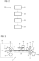
- FIG 2 shows a method 100 for clearing scrap from a metal strip production line, in particular a combined casting and rolling plant.
- a method step S1 the metal strip located in the metal strip production line is divided into the first metal strip section and the second metal strip section.
- the first metal strip section is located in front of the second metal strip section in the transport direction.
- the metal strip is expediently divided manually, for example by means of appropriate flame cuts. This makes it possible in particular to separate the cobble from the metal strip.
- a strip section forming the cobble expediently corresponds to at least part of the first metal strip section.
- the second metal strip section expediently corresponds to the section of the metal strip that will be used after the production line is restarted. can in principle be further processed, but would then not meet the specified quality criteria.
- the first metal strip section cut out of the metal strip is removed from the metal strip production line in a further process step S2. This is also conveniently carried out manually.
- an indoor crane can be used for this purpose.
- the metal strip or the second metal strip section can again be transported unhindered in the transport direction through the metal strip production line.
- the second metal strip section is expediently conveyed through the metal strip production line, past the reels, to the scrap removal system.
- the second metal strip section can be divided into a large number of metal strip pieces by means of a cutting device of the scrap removal system. The metal strip pieces can be collected, for example in a container arranged downstream of the cutting device, and then transported away with little effort.
- the conveyance of the second metal strip section in process step S3 can be at least partially automated.
- the cutting of the second metal strip section in process step S4 can also be at least partially automated.
- the conveyance in process step S3 and the cutting in process step S4 can also be understood together as a scrapping step in which the metal strip or the second metal strip section is gradually moved a little in the transport direction and an area at the head end, i.e. the front end of the strip in the transport direction, is cut off.
- FIG 3 shows a scrap removal system 1, for example for the production line 50 from FIG 1 , in detail.
- the scrap clearance system 1 has a cutting means 10, a strip catcher 20 arranged upstream of the cutting means 10 in the transport direction T of a metal strip 2, a first transport means 30, a second transport means 32 and a container 40.
- the cutting means 10 is designed to cut the metal strip 2 fed to the scrap clearance system 1 and to be scrapped into metal strip pieces 3, which are caught by the container 40.
- the metal strip 2 can be fed to the scrap removal system 1, for example, by means of a lower driver roller 67 that is longitudinally adjustable parallel to the transport direction T in the area of a last reel 61 of the production line 50.
- the metal strip 2 runs between the lower driver roller 67 and an upper driver roller 68 that is fixed in position in the transport direction T.
- the metal strip 2 can run in the direction of the reel 61 below the lower driver roller 67.
- the rotation axes 69 and 70 are positioned at the same height in the transport direction T so that a tangent of the lower driver roller 67 or the upper driver roller 68 at the intersection of the connecting line which connects the rotation axes 69 and 70 with each other and the lower driver roller 67 or the upper driver roller 68 runs parallel to the transport direction T, the metal strip 2 can continue to run in the transport direction T.
- the first transport means 30, for example a roller conveyor or roller table with a plurality of FIG 3 indicated transport rollers 31. For reasons of clarity, only one of the transport rollers 31 is provided with a reference number. Expediently, at least some of the transport rollers 31 can be actively driven, for example by means of a motor (not shown).
- the first transport means 30 thus enables the metal strip 2 to be conveyed in the transport direction T, in particular past the strip catcher 20, to the cutting means 10.
- the second transport means 32 for example in the form of a driver roller, is provided, preferably on an (upper) side of the metal strip 2 facing away from the first transport means 30, so that the metal strip 2 can run through between the first and second transport means 30, 32.
- the lower driver roller 67 and upper driver roller 68 arranged in the transport direction T in front of the scrap clearance system 1 can also serve to transport the metal strip 2 in the scrap clearance system 1 or at least support the transport.
- the driver rollers 67, 68 can transport the metal strip 2 to be scrapped to or into the cutting means 10 or at least a metal strip section through the cutting means 10.
- the belt catcher 20 has a catch arm 21 which can be pivoted between a catch position indicated by dots, in which the catch arm 21 blocks the transport of the metal belt 2 through the scrap removal system 1, and a release position in which the metal belt 2 can pass through the belt catcher 20.
- the catch arm 21 can thus in particular prevent the metal belt 2 from being transported beyond the end of the production line 50 during normal operation of the production line 50 in the event of a malfunction, for example an unsuccessful threading of a front end of the belt in the transport direction T into the last reel, in the example the reel 61, and thereby possibly endangering material and people in an area at the end of the production line 50.
- the catch arm 21 can in particular be a hydraulically actuated catch arm 21.
- the cutting means 10 expediently has two cutting tools 11, 12, for example two cutting edges or a cutting edge and an anvil, which are arranged in such a way that the metal strip 2 can be guided between them in the transport direction T.
- the cutting tools 11, 12 can be moved towards one another so that a piece of metal strip 3 is severed.
- the cutting means 10 can be designed as a strip shear with cutting tools 11, 12 that are stationary in the transport direction T, in particular as a hydraulically actuated toggle lever shear.
- the metal strip 2 can be transported step by step in the transport direction T and a piece of metal strip 3 can be cut off at a time.
- the metal strip 2 can be continuously conveyed through the scrap removal system 1 and to be cut up using a suitably configured cutting device 10, such as a drum or pendulum shear. This can accelerate the scrapping of the metal strip 2 even further.
- a suitably configured cutting device 10 such as a drum or pendulum shear. This can accelerate the scrapping of the metal strip 2 even further.
- the container 40 which is also referred to as a scrap bucket, is expediently arranged directly behind the cutting means 10 in the transport direction T.
- the container 40 can in particular be arranged in such a way that the separated metal strip pieces 3 do not have to be transported further, but instead automatically fall into the container 40 after being separated from the metal strip 2.
- the container 40 is expediently arranged slightly below a level defined by the metal strip 2. If necessary, a guide for the metal strip pieces 3 can also be provided in order to ensure reliable collection by the container 40.
Landscapes
- Engineering & Computer Science (AREA)
- Mechanical Engineering (AREA)
- Metal Rolling (AREA)
- Manufacture And Refinement Of Metals (AREA)
Abstract
Description
- Die vorliegende Erfindung betrifft ein Schrott-Räumungssystem für eine Metallband-Fertigungsstraße, insbesondere eine Gieß-Walz-Verbundanlage, eine Metallband-Fertigungsstraße mit einem solchen Schrott-Räumungssystem sowie ein Verfahren zum Räumen von Schrott aus einer Metallband-Fertigungsstraße.
- In Metallband-Fertigungsstraßen, insbesondere Gieß-Walz-Verbundanlagen für die Endlosbandproduktion (englisch endless strip production plant), werden (kontinuierlich) gegossene Stränge oder daraus gefertigte Brammen mittels einer Walzstraße zu Bändern gewalzt. Am Ende jeder Fertigungsstraße kann das gewalzte Band dann von einem Haspel aufgewickelt werden. Hat der beim Wickeln entstehende Metallbund (englisch coil) eine vorgegebene Größe bzw. das aufgewickelte Band eine vorgegebene Länge erreicht, wird das Band mithilfe einer mitlaufenden Bandschere, die der Geschwindigkeit des Bandes folgt, etwa einer Trommelschere oder dergleichen, in Transportrichtung vor dem Haspel zerteilt. Es kann dann mit dem Wickeln eines neuen Metallbundes begonnen werden. Um eine kontinuierliche Produktion zu ermöglichen, sind üblicherweise weitere Haspel vorgesehen, denen das gewalzte Band selektiv zugeführt werden kann.
- Besonders bei dünn gewalzten Bändern, beispielsweise mit einer Dicke von 1 mm oder weniger, können durch Ausfall von Komponenten der Fertigungsstraße oder beim Einfädeln des Bandes in den Haspel aufgrund der im Vergleich zu dickeren Bändern hohen Elastizität bzw. Biegsamkeit und der hohen Fördergeschwindigkeit Probleme auftreten. Beispielsweise kann sich ein sogenannter "Cobble", d. h. eine starke Verformung des Bands in einem Bandabschnitt, ausbilden, das ein weiteres Fördern des Bands verhindert. In diesem Fall muss der Betrieb der Fertigungsstraße bzw. Gieß-Walz-Verbundanlage unterbrochen und der betroffene Abschnitt des Bands entfernt werden. Dazu ist ein manuelles Zerteilen des Bandes, etwa durch mehrere Brennschnitte, und ein Abheben des Bands aus der Fertigungsstraße, etwa mittels eines Hallenkrans, notwendig. Ein derartiges Vorgehen ist aufgrund der Länge des zu entfernenden Bandabschnitts üblicherweise sehr aufwändig. Beispielsweise muss beim Auftreten eines Cobbles im Haspelbereich das zu verschrottende Band über eine Länge von einem Eingang eines Induktionsofens vor einer Fertigwalzstraße bis zum Haspelbereich und dabei auch aus einem Laminarkühlungsbereich zwischen der Fertigwalzstraße und dem Haspelbereich entfernt werden. Nachträglich muss dieser Schrott manuell in ein händelbares Format geschnitten und entsorgt werden.
- Es ist eine Aufgabe der vorliegenden Erfindung, das Verschrotten eines Bandabschnitts in einer Metallband-Fertigstraße zu verbessern, insbesondere zu erleichtern und/oder zu beschleunigen.
- Diese Aufgabe wird gelöst durch ein Schrott-Räumungssystem für eine Metallband-Fertigungsstraße, eine Metallband-Fertigungsstraße und ein Verfahren zum Räumen von Schrott aus einer Metallband-Fertigungsstraße gemäß den unabhängigen Ansprüchen.
- Bevorzugte Ausführungsformen sind Gegenstand der unabhängigen Ansprüche sowie der folgenden Beschreibung.
- Ein Schrott-Räumungssystem für eine Metallband-Fertigungsstraße, insbesondere eine Gieß-Walz-Verbundanlage, gemäß einem ersten Aspekt der Erfindung weist ein Zerteilmittel zum Zerteilen eines dem Schrott-Räumungssystem zugeführten Metallbands und einen in einer Transportrichtung des Metallbands vor dem Zerteilmittel angeordneten Bandfänger auf. Der Bandfänger weist dabei einen schwenkbar gelagerten Fangarm auf.
- Ein Zerteilmittel im Sinne der vorliegenden Erfindung ist vorzugsweise eine Vorrichtung, die zum Zerteilen eines Metallbands eingerichtet ist. Das Zerteilmittel kann ein Metallband beispielsweise in einen ersten Bandabschnitt und einen bezüglich einer Transportrichtung darauffolgenden zweiten Bandabschnitt zerteilen. Das Zerteilmittel kann beispielsweise als Bandschere, etwa als hydraulisch betätigbare Kniehebelschere, ausgebildet sein.
- Ein Bandfänger im Sinne der vorliegenden Erfindung ist vorzugsweise eine Vorrichtung, die zum Auf- oder Abfangen eines Metallbands, insbesondere eines einlaufenden Metallbandkopfendes, eingerichtet ist. Der Bandfänger kann beispielsweise verhindern, dass das Metallband unkontrolliert oder zumindest ungebremst über das Ende einer Fertigungsstraße, insbesondere eine Gieß-Walz-Verbundanlage, hinaus befördert wird. Dazu weist ein konventioneller Bandfänger einen den Transportweg des Metallbands blockierenden Fangkorb auf. Ein Bandfänger ist zweckmäßigerweise in einer Transportrichtung hinter dem letzten Haspel in der Fertigungsstraße angeordnet.
- Ein Aspekt der Erfindung basiert auf dem Ansatz, eine Anordnung aus einem Zerteilmittel zum Zerteilen eines Metallbands und, bezüglich einer Transportrichtung des Metallbands, stromaufwärts davon einen Bandfänger mit einem schwenkbaren Fangarm vorzusehen. Diese Anordnung kann beispielsweise stromabwärts eines letzten Haspel einer Metallband-Fertigungsstraße, insbesondere Gieß-Walz-Verbundanlage, vorgesehen sein und bildet zweckmäßigerweise ein Schrott-Räumungssystem. Mithilfe des schwenkbaren Fangarms kann ein im Regelbetrieb der Fertigungsstraße blockierter Transportweg zum Zerteilmittel freigegeben werden. Das Zerteilmittel am Ende der Fertigungsstraße ermöglicht das automatische oder zumindest semi-automatische Zerkleinern eines zu verschrottenden Metallbandabschnitts, ohne dass dieser Metallbandabschnitt dazu mit hohem Aufwand aus der Fertigungsstraße herausgehoben und nachträglich (manuell) zerkleinert werden muss. Infolgedessen kann das Schrott-Räumungssystem die Entfernung eines Bandabschnitts aus der Fertigungsstraße erheblich beschleunigen und somit den mit einem Produktionsausfall verbundenen Stillstand der Anlage verkürzen. Daneben lässt sich durch das endseitige Zerteilmittel die Gefahr für Verletzungen wie etwa Schnittverletzungen oder Verbrennungen beim manuellen Zerteilen des Bands verringern. Gleichzeitig kann die Gefahr vermindert werden, Komponenten der Fertigungsstraße, etwa Rollen oder Kühlköpfe, beim Durchführen der erforderlichen Brennschnitte zu beschädigen.
- Nachfolgend werden bevorzugte Ausführungsformen der Erfindung und deren Weiterbildungen beschrieben. Diese Ausführungsformen können jeweils, soweit dies nicht ausdrücklich ausgeschlossen wird, beliebig miteinander sowie mit den im Weiteren beschriebenen Aspekten der Erfindung kombiniert werden.
- Um den Transportweg zum Zerteilmittel, insbesondere stromabwärts einer letzten Haspel der Fertigungsstraße, selektiv freigeben zu können, ist der Fangarm in einer bevorzugten Ausführungsform zwischen einer Fangstellung und einer Freigabestellung schwenkbar. Zweckmäßigerweise blockiert der Fangarm den Transportweg durch das Schrott-Räumungssystem in der Fangstellung. Beispielsweise kann der Fangarm in der Fangstellung zumindest abschnittsweise derart in einen Transportweg des Metallbands hineinragen, dass das Metallband in durch den Fangarm aus der Transportrichtung heraus in einen Fangkorb gelenkt wird. Damit kann der Fangarm in der Fangstellung zuverlässig verhindern, dass das Metallband im Regelbetrieb der Fertigungsstraße unerwünscht bis zum Zerteilmittel befördert wird. Dadurch lassen sich gegebenenfalls Beschädigungen des Zerteilmittels und/oder ein unkontrolliertes Austreten des Metallbands aus der Fertigungsstraße an deren Ende verhindern.
- In der Freigabestellung kann ein dem Schrott-Räumungssystem zugeführtes Metallband den Bandfänger dagegen zweckmäßigerweise passieren. In der Freigabestellung kann der Fangarm beispielsweise aus dem Transportweg des Metallbands herausgeschwenkt sein.
- Um in diesem Fall einen zuverlässigen Transport des Metallbands bis zum Zerteilmittel zu ermöglichen und das Metallband gegebenenfalls für das Zerteilen in geeigneter Weise zu positionieren, ist es von Vorteil, wenn ein erstes Transportmittel zum Befördern des Metallbands am Bandfänger vorbei vorgesehen ist. Das Transportmittel kann beispielsweise als Rollgang ausgebildet sein, insbesondere als Rolltisch mit mehreren Rollen. Zweckmäßigerweise ist dabei zumindest ein Teil der Rollen aktiv antreibbar, d.h. mit einem Antrieb versehen oder gekoppelt. Insofern ist das erste Transportmittel vorzugsweise ein aktives Transportmittel. Das erste Transportmittel ermöglicht auch eine nahtlose Integration des Schrott-Räumungssystems in die Fertigungsstraße, etwa indem es sich an den Transportweg zum letzten Haspel der Fertigungsstraße anschließt.
- Das erste Transportmittel erstreckt sich dabei vorzugsweise über einen Transportabschnitt in der Transportrichtung vor dem Bandfänger und einem Transportabschnitt in der Transportrichtung hinter dem Bandfänger, insbesondere bis zum Zerteilmittel. Beispielsweise können Rollen des ersten Transportmittels sowohl stromaufwärts als auch stromabwärts des Bandfängers vorgesehen sein. Insofern kann das Transportmittel das Metallband von dem letzten Haspel der Fertigungsstraße bis zum Zerteilmittel oder jedenfalls am Bandfänger vorbei befördern.
- Um die Beförderung eines im Schrott-Räumungssystem befindlichen Metallbands zu unterstützen, ist vorzugsweise ein zweites Transportmittel zum, insbesondere selektiven oder gezielten, Zuführen des Metallbands in das Zerteilmittel vorgesehen. Dieses zweite Transportmittel ist zweckmäßigerweise in der Transportrichtung hinter dem Bandfänger und unmittelbar vor dem Zerteilmittel angeordnet. Das zweite Fördermittel kann beispielsweise eine auch als Treiberrolle bezeichnete Förderrolle, die zum aktiven Transport des Metallbands eingerichtet ist, aufweisen. Das zweite Fördermittel ist zweckmäßigerweise derart angeordnet oder anordenbar, dass der Transportweg durch das Schrott-Räumungssystem zumindest abschnittsweise zwischen dem ersten und zweiten Transportmittel verläuft. Dabei ist es bevorzugt, dass das auf einer Unterseite vom ersten Transportmittel, etwa dem Rollgang, Metallband abgestützt wird, während das zweite Transportmittel, etwa die Treiberrolle, gegen eine Oberseite des Metallbands mit einem vorgegebenen Druck angestellt ist.
- Mittels des ersten und/oder zweiten Transportmittels kann ein Kopfende, d. h. in Transportrichtung vorderes Ende, des zu verschrottenden Metallbands oder Metallbandabschnitts beispielsweise derart stromabwärts des Zerteilmittels positioniert werden, dass eine Betätigung des Zerteilmittels ein handliches Metallband- oder Schrottteil erzeugt. Um dieses Schrottteil leicht abtransportieren zu können, ist vorzugsweise ein Behälter zur Aufnahme von durch das Zerteilmittel zerteilten Metallbandabschnitten vorgesehen. Der Behälter ist zweckmäßigerweise in der Transportrichtung hinter dem Zerteilmittel angeordnet, zum Beispiel in der Weise, dass die Schrottteile in den Behälter hineinfallen können. Bei dem auch als Schrottkübel bezeichneten Behälter kann es sich insbesondere um einen Container handeln.
- Die Metallband-Fertigungsstraße, insbesondere die Gieß-Walz-Verbundanlage, gemäß einem zweiten Aspekt der Erfindung weist ein Schrott-Räumungssystem nach dem ersten Aspekt der Erfindung auf. Mittels des Schrott-Räumungssystems können durch das Auftreten von Cobbles bedingte Stillstandszeiten und damit verbundene Produktionsausfälle der Fertigungsstraße verkürzt werden. Gleichzeitig ermöglicht das Schrott-Räumungssystem eine Erhöhung der Betriebssicherheit, da zum Entfernen eines Metallbandabschnitts aus der Fertigungsstraße weniger Bedienpersonal notwendig ist und insbesondere weniger manuelle Arbeitsschritte, zum Beispiel Brennschnitte, durchgeführt werden müssen. Zudem kann weniger Hallenkran-Aktivität erforderlich sein.
- Die Metallband-Fertigungsstraße kann beispielsweise eine Vorwalzstraße, einen Induktionsofen, eine Fertigwalzstraße, eine Kühlstrecke sowie einen oder mehrere Haspel aufweisen. Um das Metallband aus einer solchen Fertigungsstraße automatisch oder halbautomatisch abführen und verschrotten zu können, etwa wenn Probleme beim Einfädeln des Bands in einen der Haspel auftreten, ist das Schrott-Räumungssystem vorzugsweise nach der in der Transportrichtung des Metallbands durch die Fertigungsstraße letzten Komponente der Fertigungsstraße, insbesondere hinter des in Transportrichtung letzten Haspel, angeordnet. Das Schrott-Räumungssystem kann insbesondere an die Fertigungsstraße angehängt sein und die Fertigungsstraße damit verlängern.
- Bei einem Verfahren zum Räumen von Schrott aus einer Metallband-Fertigungsstraße, insbesondere aus einer Gieß-Walz-Verbundanlage, gemäß einem dritten Aspekt der Erfindung wird ein sich in einer Metallband-Fertigungsstraße befindliches Metallband in einen ersten Metallbandabschnitt und einen zweiten Metallbandabschnitt zerteilt, wobei der erste Metallbandabschnitt in einer Transportrichtung durch die Metallband-Fertigungsstraße vor dem zweiten Metallbandabschnitt liegt. Der erste Metallbandabschnitt kann in diesem Sinne als vorausgehender Metallbandabschnitt und der zweite Metallbandabschnitt als nachfolgender Metallbandabschnitt aufgefasst werden.
- Nach dem Zerteilen wird der erste Metallbandabschnitt aus der Metallband-Fertigungsstraße entfernt. Der zweite Metallbandabschnitt wird durch die Metallband-Fertigungsstraße bis zu einem, insbesondere stromabwärts einer letzten Haspel angeordneten, Schrott-Räumungssystem befördert. Der zweite Metallbandabschnitt wird dann mittels eines Zerteilmittels des Schrott-Räumungssystems in eine Vielzahl von Metallbandstücken, die auch als Schrottteile bezeichnet werden können, zerteilt. Das Zerteilen des zweiten Metallbandabschnitts kann automatisch oder zumindest halbautomatisch erfolgen, sodass Bedienpersonal eingespart und die Betriebssicherheit erhöht werden kann.
- Zweckmäßigerweise wird das Metallband dabei zunächst derart zerteilt, dass der erste Metallbandabschnitt ein Cobble, d. h. einen unerwünscht verformten Bandabschnitt, umfasst. Da eine derartige Verformung eine weitere Beförderung des ersten Metallbandabschnitts durch die Fertigungsstraße erschwert oder sogar unmöglich macht, wird der erste Metallbandabschnitt vorzugsweise aus der Metallband-Fertigungsstraße herausgehoben. Beispielsweise kann der erste Metallbandabschnitt mittels eines Krans aus der Fertigungsstraße herausgehoben werden.
- Um die Räumung von Schrott aus der Fertigungsstraße einleiten zu können, wird in bevorzugter Weise vor dem Befördern des zweiten Metallbandabschnitts zum Schrott-Räumungssystem ein Fangarm eines in Transportrichtung stromaufwärts des Zerteilmittels angeordneten Bandfängers des Schrott-Räumungssystems von einer Fangstellung in eine Freigabestellung geschwenkt. Zweckmäßigerweise blockiert der Fangarm in der Fangstellung einen Transportweg durch das Schrott-Räumungssystem. Insbesondere kann der Fangarm in der Fangstellung zuverlässig verhindern, dass das Metallband im Regelbetrieb der Fertigungsstraße unerwünscht bis zum Zerteilmittel befördert wird. Dadurch lassen sich gegebenenfalls Beschädigungen des Zerteilmittels und/oder ein unkontrolliertes Austreten des Metallbands aus der Fertigungsstraße an deren Ende verhindern.
- In der Freigabestellung kann das dem Schrott-Räumungssystem zugeführte Metallband den Bandfänger dagegen zweckmäßigerweise passieren.
- Ist der Transportweg in das Schrott-Räumungssystem hinein bzw. durch das Schrott-Räumungssystem hindurch freigegeben, kann das bis zum Zerteilmittel beförderte Metallband in Metallbandstücke zerteilt werden. In bevorzugter Weise werden die Metallbandstücke in einen in der Transportrichtung hinter dem Zerteilmittel angeordneten Behälter befördert. Beispielsweise können die Metallbandstücke in den auch als Schrottkübel bezeichneten Behälter hineinfallen. Das Sammeln der Schrottstücke in den Behälter erlaubt einen leichten und effizienten Abtransport dieser Schrottteile.
- Eine weitere Effizienzsteigerung der Verschrottung von Metallbandabschnitten in der Fertigungsstraße kann erreicht werden, indem lediglich das Teilen des Metallbands in den ersten und den zweiten Metallbandabschnitt und das Entfernen des ersten Metallbandabschnitts manuell erfolgen. Dagegen erfolgt zumindest das Zerteilen des zweiten Metallbandabschnitts mittels des Zerteilmittels in eine Vielzahl von Metallbandstücken, vorzugsweise jedoch auch das Befördern des zweiten Metallbandabschnitts zum Schrott-Räumungssystem, insbesondere durch das Schrott-Räumungssystem zum Zerteilmittel, zweckmäßigerweise automatisch oder semiautomatisch. Dies bedeutet, dass eine Steuerung oder Bedienung der Fertigungsstraße, insbesondere des Schrott-Räumungssystems, zum Beispiel von entsprechenden Fördereinrichtungen und/oder der des Zerteilmittels, durch Bedienpersonal nicht oder nur in geringem Umfang notwendig ist, zumindest insoweit der zweite Metallbandabschnitt betroffen ist.
- Die Eigenschaften, Merkmale und Vorteile dieser Erfindung sowie die Art und Weise, wie diese erreicht werden, werden klarer und deutlicher verständlich im Zusammenhang mit der folgenden Beschreibung eines Ausführungsbeispiels, das im Zusammenhang mit den Zeichnungen näher erläutert wird. Dabei zeigen, zumindest teilweise schematisch:
- FIG 1
- ein Beispiel einer Metallband-Fertigungsstraße mit einem Schrott-Räumungssystem;
- FIG 2
- ein Beispiel eines Verfahrens zum Räumen von Schrott aus einer Metallband-Fertigungsstraße; und
- FIG 3
- ein Beispiel eines Schrott-Räumungssystems.
- Soweit zweckdienlich, werden in den Figuren dieselben Bezugszeichen für dieselben oder einander entsprechende Elemente der Erfindung verwendet.
-
FIG 1 zeigt ein Beispiel einer Metallband-Fertigungsstraße 50 mit einem Schrott-Räumungssystem 1. Neben dem Schrott-Räumungssystem 1 weist die Metallband-Fertigungsstraße 50, im vorliegenden Beispiel eine Gieß-Walz-Verbundanlage zur Endlosproduktion von Metallbändern 2, eine Gießmaschine 51, Entzunderungsvorrichtungen 53, eine Vorwalzstraße 54, einen Induktionsofen 55, eine Fertigwalzstraße 56, eine Kühlstrecke 57, ein Zerteilmittel 58 sowie mehrere, im vorliegenden Beispiel drei, Haspeln 59, 60, 61 auf. Das Schrott-Räumungssystem 1 schließt sich bezüglich einer Transportrichtung T des Metallbands 2 durch die Fertigungsstraße 50 stromabwärts der letzten Haspel 61 an. - Mittels einer Kokille 62 der Gießmaschine 51 wird ein teilerstarrter Metallstrang 63 hergestellt. Auf die Gießmaschine 51 folgt die Entzunderungsvorrichtung 53 zur Entzunderung des Strangs 63. Anschließend wird der Strang 63 durch mehrere, im gezeigten Beispiel drei, Vorwalzgerüste 64a, 64b, 64c der Vorwalzstraße 54 zu einem Vorband 65 gewalzt. Das Vorband 65 wird durch den Induktionsofen 55 erhitzt und durch eine weitere Entzunderungsvorrichtung 53 abermals entzundert, um ein Einwalzen von Zunder in das Band in der nachfolgenden Fertigwalzstraße 56 vermeiden zu können. Um die gewünschte endgültige Banddicke zu erhalten, weist die Fertigwalzstraße 56 mehrere, im gezeigten Beispiel fünf, Fertigwalzgerüste 66a, 66b, 66c, 66d, 66e auf. In der Kühlstrecke 57, zum Beispiel einem Laminarkühlbereich, wird das so dünn gewalzte Metallband 2 auf eine zum Aufwickeln geeignete Temperatur gekühlt. Nachdem ein mittels einer der drei Haspeln 59, 60, 61 gewickelter Metallbund aus aufgewickeltem Metallband 2 eine vorgegebene Größe erreicht hat, kann das Metallband 2 mittels des Zerteilmittels 58 geschnitten und auf einem anderen der drei Haspeln 59, 60, 61 weiter zu einem neuen Metallbund gewickelt werden.
- Insbesondere beim Wechseln der gerade aktiven Haspel 59, 60, 61, d. h. beim Einfädeln des Metallbands 2 in eine andere Haspel 59, 60, 61, kann es aufgrund der im Vergleich zum Strang 63 oder zum Vorband 65 hohen Elastizität bzw. Biegsamkeit des Metallbands 2 zu Deformationen des Metallbands 2 kommen. Ein derart deformierter Bereich des Metallbands 2 kann dann nicht weiter transportiert bzw. gewickelt werden, sodass es zu einem Aufstauen des Metallbands 2 kommt.
- Eine ungewollte Verformung des Metallbands 2 und das damit verbundene Aufstauen können grundsätzlich aber auch an anderen Komponenten der Fertigstraße 50 auftreten. Dies ist insbesondere dann der Fall, wenn in Transportrichtung T vor der Vorwalzstraße 54 oder der Fertigwalzstraße 56 weitere Zerteilmittel (nicht gezeigt) vorgesehen sind, etwa um Brammen herzustellen oder das Metallband 2 nach Erreichen einer vorgegebenen Länge zu schneiden.
- Das Aufstauen und die damit verbundene weitere Deformation des Metallbands 2 wird als "Cobble" 71 bezeichnet und erzwingt ein Stoppen der Produktion in der Fertigungsstraße 50. Um die Fertigungsstraße 50 wieder in Betrieb nehmen zu können, muss der Cobble 71 zunächst entfernt werden. Da sich durch den Stillstand der Fertigungsstraße 50 und die sich anschließende Wiederaufnahme des Betriebs undefinierte Fertigungsparameter ergeben oder zumindest die vorgegebenen Fertigungsparameter nicht eingehalten werden können, tritt häufig der Fall auf, dass ein sich bei der Wiederaufnahme des Betriebs im Bereich der Kühlstrecke 57 und/oder der Fertigwalzstraße 56 befindlicher Abschnitt des Metallbands 2 etwaige vorgegebene Qualitätskriterien nicht erfüllt. Deshalb muss neben dem Cobble 71 bzw. einem den Cobble 71 enthaltenden ersten Metallbandabschnitt 2a auch dieser zusätzliche zweite Metallbandabschnitt 2b aus der Fertigungsstraße 50 entfernt werden. Dazu kann das Schrott-Räumungssystem 1 genutzt werden, wie im Folgenden im Zusammenhang mit
FIG 2 erläutert wird. -
FIG 2 zeigt ein Verfahren 100 zum Räumen von Schrott aus einer Metallband-Fertigungsstraße, insbesondere einer Gieß-Walz-Verbundanlage. - In einem Verfahrensschritt S1 wird das sich in der Metallband-Fertigungsstraße befindliche Metallband in den ersten Metallbandabschnitt und den zweiten Metallbandabschnitt zerteilt. Der erste Metallbandabschnitt liegt dabei in der Transportrichtung vor dem zweiten Metallbandabschnitt. Das Zerteilen des Metallbands wird dabei zweckmäßigerweise manuell durchgeführt, zum Beispiel mittels entsprechender Brennschnitte. Dadurch kann insbesondere der Cobble aus dem Metallband herausgetrennt werden. Zweckmäßigerweise korrespondiert ein den Cobble bildender Bandabschnitt entsprechend mit wenigstens einem Teil des ersten Metallbandabschnitts. Entsprechend korrespondiert der zweite Metallbandabschnitt zweckmäßigerweise mit demjenigen Abschnitt des Metallbands, der nach der Wiederinbetriebnahme der Fertigungsstraße zwar grundsätzlich weiterverarbeitet werden kann, dann aber die vorgegebenen Qualitätskriterien nicht erfüllen würde.
- Der aus dem Metallband herausgetrennte erste Metallbandabschnitt wird in einem weiteren Verfahrensschritt S2 aus der Metallband-Fertigungsstraße entfernt. Dies wird zweckmäßigerweise ebenfalls manuell durchgeführt. Dazu kann beispielsweise ein Hallenkran eingesetzt werden.
- Durch Entfernung des ersten Metallbandabschnitts, insbesondere des darin enthaltenen, den Cobble bildenden Bandabschnitts, aus der Fertigungsstraße kann das Metallband bzw. der zweite Metallbandabschnitt wieder ungehindert in der Transportrichtung durch die Metallband-Fertigungsstraße transportiert werden. Entsprechend wird in einem weiteren Verfahrensschritt S3 der zweite Metallbandabschnitt zweckmäßigerweise durch die Metallband-Fertigungsstraße, vorbei an den Haspeln, bis zu dem Schrott-Räumungssystem befördert. Dort kann der zweite Metallbandabschnitt in einem weiteren Verfahrensschritt S4 mittels eines Zerteilmittels des Schrott-Räumungssystems in eine Vielzahl von Metallbandstücken zerteilt werden. Die Metallbandstücke lassen sich sammeln, etwa in einem stromabwärts des Zerteilmittels angeordneten Behälter, und dann aufwandsarm abtransportieren.
- Die Beförderung des zweiten Metallbandabschnitts in Verfahrensschritt S3 kann dabei zumindest teilweise automatisiert erfolgen. Alternativ oder zusätzlich kann auch das Zerteilen des zweiten Metallbandabschnitts in Verfahrensschritt S4 zumindest teilweise automatisiert erfolgen. Die Beförderung in Verfahrensschritt S3 und das Zerteilen in Verfahrensschritt S4 können zusammen auch als Verschrottungsschritt verstanden werden, in dem das Metallband bzw. der zweite Metallbandabschnitt schrittweise ein Stück in Transportrichtung bewegt und ein Bereich am Kopfende, d. h. dem in Transportrichtung vorderen Bandende, abgeschnitten wird.
-
FIG 3 zeigt ein Schrott-Räumungssystem 1, zum Beispiel für die Fertigungsstraße 50 ausFIG 1 , im Detail. Das Schrott-Räumungssystem 1 weist ein Zerteilmittel 10, einen in Transportrichtung T eines Metallbands 2 stromaufwärts des Zerteilmittels 10 angeordneten Bandfänger 20, ein erstes Transportmittel 30, ein zweites Transportmittel 32 und einen Behälter 40 auf. Das Zerteilmittel 10 ist dazu eingerichtet, das dem Schrott-Räumungssystem 1 zugeführte und zu verschrottende Metallband 2 in Metallbandstücke 3 zu zerteilen, die von dem Behälter 40 aufgefangen werden. - Das Zuführen des Metallbands 2 zum Schrott-Räumungssystem 1 kann beispielsweise mittels einer parallel zur Transportrichtung T längsverstellbaren unteren Treiberrolle 67 im Bereich einer letzten Haspel 61 der Fertigungsstraße 50 erfolgen. Das Metallband 2 läuft dabei zwischen der unteren Treiberrolle 67 und einer in Transportrichtung T ortsfest angeordneten oberen Treiberrolle 68 hindurch. Ist eine Drehachse 70 der unteren Treiberrolle 67 in Transportrichtung T vor einer Drehachse 69 der oberen Treiberrolle 68 positioniert, sodass eine Tangente der unteren Treiberrolle 67 oder der oberen Treiberrolle 68 im Schnittpunkt einer Verbindungslinie, welche die Drehachsen 69 und 70 miteinander verbindet, und der unteren Treiberrolle 67 bzw. der oberen Treiberrolle 68 gegenüber der Transportrichtung T verkippt, kann das Metallband 2 in Richtung der Haspel 61 unterhalb der unteren Treiberrolle 67 laufen. Sind die Drehachsen 69 und 70 dagegen in Transportrichtung T auf gleicher Höhe positioniert, sodass eine Tangente der unteren Treiberrolle 67 oder der oberen Treiberrolle 68 im Schnittpunkt der Verbindungslinie, welche die Drehachsen 69 und 70 miteinander verbindet, und der unteren Treiberrolle 67 bzw. oberen Treiberrolle 68 parallel zur Transportrichtung T verläuft, kann das Metallband 2 weiter in der Transportrichtung T laufen.
- Zum Transport des Metallbands 2 im Schrott-Räumungssystem 1 dient das erste Transportmittel 30, zum Beispiel ein Rollgang oder Rolltisch mit einer Vielzahl von in
FIG 3 angedeuteten Transportrollen 31. Aus Gründen der Übersichtlichkeit ist hierbei nur eine der Transportrollen 31 mit einem Bezugszeichen versehen. Zweckmäßigerweise ist zumindest ein Teil der Transportrollen 31 aktiv antreibbar, etwa mittels eines nicht dargestellten Motors. Das erste Transportmittel 30 ermöglicht so eine Beförderung des Metallbands 2 in der Transportrichtung T insbesondere am Bandfänger 20 vorbei bis zum Zerteilmittel 10. Um das Metallband 2 bei dieser Beförderung abstützen zu können, ist das zweite Transportmittel 32, etwa in Form einer Treiberrolle, vorgesehen, und zwar vorzugsweise auf einer dem ersten Transportmittel 30 abgewandten (Ober-) Seite des Metallbands 2, sodass das Metallband 2 zwischen dem ersten und zweiten Transportmittel 30, 32 hindurchlaufen kann. - Selbstverständlich können auch die in Transportrichtung T vor dem Schrott-Räumungssystem 1 angeordnete untere Treiberrolle 67 und obere Treiberrolle 68 zum Transport des Metallbands 2 im Schrott-Räumungssystem 1 dienen oder den Transport zumindest unterstützen. Insbesondere können alternativ oder zusätzlich zu dem ersten und/oder zweiten Transportmittel 30, 32 die Treiberrollen 67, 68 das zu verschrottende Metallband 2 zum oder in das Zerteilmittel 10 oder zumindest einen Metallbandabschnitt durch das Zerteilmittel 10 befördern.
- Der Bandfänger 20 weist einen Fangarm 21 auf, der zwischen einer gepunktet angedeuteten Fangstellung, in welcher der Fangarm 21 den Transport des Metallbands 2 durch das Schrott-Räumungssystem 1 blockiert, und einer Freigabestellung, in welcher das Metallband 2 den Bandfänger 20 passieren kann, schwenkbar ist. In der Fangstellung kann der Fangarm 21 so insbesondere verhindern, dass das Metallband 2 im Regelbetrieb der Fertigungsstraße 50 bei einer Fehlfunktion, beispielsweise einem missglückten Einfädeln eines in Transportrichtung T vorderen Bandendes in den letzten Haspel, im Beispiel der Haspel 61, über das Ende der Fertigungsstraße 50 hinaus befördert wird und dabei möglicherweise Material und Personen in einem Bereich am Ende der Fertigungsstraße 50 gefährdet.
- Der Fangarm 21 kann insbesondere ein hydraulisch betätigbarer Fangarm 21 sein.
- Zweckmäßigerweise weist das Zerteilmittel 10 zwei Schneidewerkzeuge 11, 12, etwa zwei Schneiden oder eine Schneide und einen Amboss, auf, die derart angeordnet sind, dass das Metallband 2 in Transportrichtung T zwischen ihnen hindurchführbar ist. Wenn eine vorgegebene Länge des Metallbands 2 durch die Schneidewerkzeuge 11, 12 hindurch befördert wurde, können die Schneidewerkzeuge 11, 12 aufeinander zu bewegt werden, sodass ein Metallbandstück 3 abgetrennt wird. Da beim Verschrotten des Metallbands 2, anders als im regulären Betrieb einer Gieß-Walz-Verbundanlage, in dem kontinuierlich ein Metallstrang erzeugt und abtransportiert werden muss, kein kontinuierlicher Transport des Metallbands 2 notwendig ist, kann das Zerteilmittel 10 als Bandschere mit in Transportrichtung T ortsfesten Schneidewerkzeugen 11, 12, insbesondere als hydraulisch betätigbare Kniehebelschere, ausgebildet sein. Eine aufwändigere Trommel- oder Pendelschere mit abschnittsweise mitlaufenden Schneidewerkzeugen ist nicht notwendig. Mittels des Transportmittels 30 und des Fördermittels 32 kann das Metallband 2 schrittweise in Transportrichtung T transportiert und jeweils ein Metallbandstück 3 abgetrennt werden.
- Alternativ ist aber auch eine kontinuierliche Beförderung des Metallbands 2 durch das Schrott-Räumungssystem 1 und das Zerteilen mittels eines entsprechend eingerichteten Zerteilmittels 10, etwa einer Trommel- oder Pendelschere, denkbar. Dadurch kann die Verschrottung des Metallbands 2 noch weiter beschleunigt werden.
- Der Behälter 40, der auch als Schrottkübel bezeichnet wird, ist zweckmäßigerweise unmittelbar in Transportrichtung T hinter dem Zerteilmittel 10 angeordnet. Der Behälter 40 kann insbesondere derart angeordnet sein, dass die abgetrennten Metallbandstücke 3 nicht weiter transportiert werden müssen, sondern nach dem Abtrennen vom Metallband 2 automatisch in den Behälter 40 fallen. Zu diesem Zweck ist der Behälter 40 zweckmäßigerweise etwas unterhalb einer durch das Metallband 2 definierten Ebene angeordnet. Gegebenenfalls kann auch eine Führung für die Metallbandstücke 3 vorgesehen sein, um ein zuverlässiges Auffangen durch den Behälter 40 sicherzustellen.
- Obwohl die Erfindung im Detail durch die bevorzugten Ausführungsbeispiele näher illustriert und beschrieben wurde, so ist die Erfindung nicht durch die offenbarten Beispiele eingeschränkt und andere Variationen können vom Fachmann hieraus abgeleitet werden, ohne den Schutzumfang der Erfindung zu verlassen.
-
- 1
- Schrott-Räumungssystem
- 2
- Metallband
- 2a, 2b
- erster, zweiter Metallbandabschnitt
- 3
- Metallbandstück
- 10
- Zerteilmittel
- 11, 12
- Schneidewerkzeuge
- 20
- Bandfänger
- 21
- Fangarm
- 30
- erstes Transportmittel
- 31
- Transportrolle
- 32
- zweites Transportmittel
- 40
- Behälter
- 50
- Metallband-Fertigungsstraße
- 51
- Gießmaschine
- 53
- Entzunderungsvorrichtung
- 54
- Vorwalzstraße
- 55
- Induktionsofen
- 56
- Fertigwalzstraße
- 57
- Kühlstrecke
- 58
- Zerteilmittel
- 59, 60, 61
- Haspel
- 62
- Kokille
- 63
- Metallstrang
- 64a-c
- Vorwalzgerüst
- 65
- Vorband
- 66a-e
- Fertigwalzgerüst
- 67
- untere Treiberrolle
- 68
- obere Treiberrolle
- 69, 70
- Drehachse
- 71
- Cobble
- 100
- Verfahren
- S 1-4
- Verfahrensschritte
- T
- Transportrichtung
Claims (12)
- Schrott-Räumungssystem (1) für eine Metallband-Fertigungsstraße (50), insbesondere eine Gieß-Walz-Verbundanlage, mit einem Zerteilmittel (10) zum Zerteilen eines dem Schrott-Räumungssystem (1) zugeführten Metallbands (2) und einem in einer Transportrichtung (T) des Metallbands (2) hinter dem Zerteilmittel (10) angeordneten Bandfängers (20), der einen schwenkbar gelagerten Fangarm (21) aufweist.
- Schrott-Räumungssystem (1) nach Anspruch 1, wobei der Fangarm (21) zwischen einer Fangstellung, in welcher der Fangarm (21) einen Transportweg durch das Schrott-Räumungssystem (1) blockiert, und einer Freigabestellung, in welcher ein dem Schrott-Räumungssystem (1) zugeführtes Metallband (2) den Bandfänger (20) passieren kann, schwenkbar ist.
- Schrott-Räumungssystem (1) nach einem der Ansprüche 1 oder 2, aufweisend ein erstes Transportmittel (30) zum Befördern des Metallbands (2) am Bandfänger (20) vorbei, wobei sich das erste Transportmittel (30) über einen Transportabschnitt in der Transportrichtung (T) vor dem Bandfänger (20) und einen Transportabschnitt in der Transportrichtung (T) hinter dem Bandfänger erstreckt.
- Schrott-Räumungssystem (1) nach einem der vorangehenden Ansprüche, aufweisend ein zweites Transportmittel (32) zum Zuführen des Metallbands (2) in das Zerteilmittel (10), wobei das zweite Transportmittel (32) in der Transportrichtung (T) hinter dem Bandfänger (20) und unmittelbar vor dem Zerteilmittel (10) derart angeordnet oder anordenbar ist, dass ein Transportweg durch das Schrott-Räumungssystem (1) zumindest abschnittsweise zwischen dem ersten und zweiten Fördermittel (30, 32) verläuft.
- Schrott-Räumungssystem (1) nach einem der vorangehenden Ansprüche, aufweisend einen in der Transportrichtung (T) hinter dem Zerteilmittel (10) angeordneten Behälter (40) zur Aufnahme von durch das Zerteilmittel (10) zerteilten Metallbandabschnitten (2b).
- Metallband-Fertigungsstraße (50), insbesondere Gieß-Walz-Verbundanlage, mit einem Schrott-Räumungssystem (1) nach einem der vorangehenden Ansprüche.
- Metallband-Fertigungsstraße (50) nach Anspruch 6, wobei das Schrott-Räumungssystem (1) in einer Transportrichtung (T) eines Metallbands (2) durch die Fertigungsstraße (50) hinter einer in Transportrichtung (T) letzten Haspel (61) angeordnet ist.
- Verfahren (100) zum Räumen von Schrott aus einer Metallband-Fertigungsstraße (50), insbesondere einer Gieß-Walz-Verbundanlage, aufweisend:- Zerteilen (S1) eines sich in einer Metallband-Fertigungsstraße (50) befindlichen Metallbands (2) in einen ersten Metallbandabschnitt (2a) und einen zweiten Metallbandabschnitt (2b), wobei der erste Metallbandabschnitt (2a) in einer Transportrichtung (T) durch die Metallband-Fertigungsstraße (50) vor dem zweiten Metallbandabschnitt (2b) liegt;- Entfernen (S2) des ersten Metallbandabschnitts (2a) aus der Metallband-Fertigungsstraße (50),- Befördern (S3) des zweiten Metallbandabschnitts (2b) durch die Metallband-Fertigungsstraße (50) bis zu einem Schrott-Räumungssystem (1); und- Zerteilen (S4) des zweiten Metallbandabschnitts (2b) mittels eines Zerteilmittels (10) des Schrott-Räumungssystems (1) in eine Vielzahl von Metallbandstücken (3).
- Verfahren (100) nach Anspruch 8, wobei der erste Metallbandabschnitt (2a) aus der Metallband-Fertigungsstraße (50) herausgehoben wird.
- Verfahren (100) nach Anspruch 8 oder 9, wobei vor dem Befördern des zweiten Metallbandabschnitts (2b) zum Schrott-Räumungssystem (1) ein Fangarm (21) eines in Transportrichtung (T) vor dem Zerteilmittel (10) angeordneten Bandfängers (20) des Schrott-Räumungssystems (1) aus einer Fangstellung, in welcher der Fangarm (21) einen Transportweg durch das Schrott-Räumungssystem (1) blockiert, in eine Freigabestellung, in welcher der zweite Metallbandabschnitt (2b) den Bandfänger (20) passieren kann, geschwenkt wird.
- Verfahren (100) nach einem der Ansprüche 8 bis 10, wobei die Metallbandstücke (3) in einen in der Transportrichtung (T) hinter dem Zerteilmittel (10) angeordneten Behälter (40) befördert werden.
- Verfahren (100) nach einem der Ansprüche 8 bis 11, wobei- das Zerteilen des Metallbands (2) in den ersten und zweiten Metallbandabschnitt (2a, 2b) und das Entfernen des ersten Metallbandabschnitts (2a) manuell erfolgen und- das Zerteilen des zweiten Metallbandabschnitts (2b) mittels des Zerteilmittels (10) in eine Vielzahl von Metallbandstücken (3) automatisch oder semiautomatisch erfolgt.
Priority Applications (6)
| Application Number | Priority Date | Filing Date | Title |
|---|---|---|---|
| EP23157217.3A EP4417332B1 (de) | 2023-02-17 | 2023-02-17 | Schrott-räumungssystem, metallband-fertigungsstrasse und schrotträumverfahren |
| ES23157217T ES3058096T3 (en) | 2023-02-17 | 2023-02-17 | Scrap-removing system, metal strip production line, and scrap-removing method |
| US19/155,786 US20260233273A1 (en) | 2023-02-17 | 2023-12-18 | Scrap clearing system, metal-strip production line, and scrap clearing method |
| EP23833726.5A EP4665517A1 (de) | 2023-02-17 | 2023-12-18 | Schrott-räumungssystem, metallband-fertigungsstrasse und schrotträumverfahren |
| CN202380094118.2A CN120712151A (zh) | 2023-02-17 | 2023-12-18 | 废料清理系统、金属带生产线及废料清理方法 |
| PCT/EP2023/086231 WO2024170135A1 (de) | 2023-02-17 | 2023-12-18 | Schrott-räumungssystem, metallband-fertigungsstrasse und schrotträumverfahren |
Applications Claiming Priority (1)
| Application Number | Priority Date | Filing Date | Title |
|---|---|---|---|
| EP23157217.3A EP4417332B1 (de) | 2023-02-17 | 2023-02-17 | Schrott-räumungssystem, metallband-fertigungsstrasse und schrotträumverfahren |
Publications (3)
| Publication Number | Publication Date |
|---|---|
| EP4417332A1 true EP4417332A1 (de) | 2024-08-21 |
| EP4417332C0 EP4417332C0 (de) | 2025-12-10 |
| EP4417332B1 EP4417332B1 (de) | 2025-12-10 |
Family
ID=85283485
Family Applications (2)
| Application Number | Title | Priority Date | Filing Date |
|---|---|---|---|
| EP23157217.3A Active EP4417332B1 (de) | 2023-02-17 | 2023-02-17 | Schrott-räumungssystem, metallband-fertigungsstrasse und schrotträumverfahren |
| EP23833726.5A Pending EP4665517A1 (de) | 2023-02-17 | 2023-12-18 | Schrott-räumungssystem, metallband-fertigungsstrasse und schrotträumverfahren |
Family Applications After (1)
| Application Number | Title | Priority Date | Filing Date |
|---|---|---|---|
| EP23833726.5A Pending EP4665517A1 (de) | 2023-02-17 | 2023-12-18 | Schrott-räumungssystem, metallband-fertigungsstrasse und schrotträumverfahren |
Country Status (5)
| Country | Link |
|---|---|
| US (1) | US20260233273A1 (de) |
| EP (2) | EP4417332B1 (de) |
| CN (1) | CN120712151A (de) |
| ES (1) | ES3058096T3 (de) |
| WO (1) | WO2024170135A1 (de) |
Cited By (1)
| Publication number | Priority date | Publication date | Assignee | Title |
|---|---|---|---|---|
| EP4744795A1 (de) * | 2024-11-19 | 2026-05-20 | Primetals Technologies Austria GmbH | Produktion von ultradünnem endlosband |
Citations (4)
| Publication number | Priority date | Publication date | Assignee | Title |
|---|---|---|---|---|
| WO2009121678A1 (de) * | 2008-04-04 | 2009-10-08 | Siemens Vai Metals Technologies Gmbh & Co | Verfahren und vorrichtung für eine giess-walz-verbundanlage |
| WO2014029544A1 (de) * | 2012-08-20 | 2014-02-27 | Siemens Vai Metals Technologies Gmbh | Verfahren und vorrichtung für eine giess-walz-verbundanlage |
| WO2015110648A1 (de) * | 2014-01-27 | 2015-07-30 | Siemens Vai Metals Technologies Gmbh | GIEß-WALZ -VERBUNDANLAGE MIT SCHWENKBAREM ROLLGANGSABSCHNITT |
| EP3120948A1 (de) * | 2014-03-20 | 2017-01-25 | Primetals Technologies Japan, Ltd. | Wicklervorrichtung und gate-vorrichtung mit führungseinheit |
-
2023
- 2023-02-17 EP EP23157217.3A patent/EP4417332B1/de active Active
- 2023-02-17 ES ES23157217T patent/ES3058096T3/es active Active
- 2023-12-18 US US19/155,786 patent/US20260233273A1/en active Pending
- 2023-12-18 CN CN202380094118.2A patent/CN120712151A/zh active Pending
- 2023-12-18 EP EP23833726.5A patent/EP4665517A1/de active Pending
- 2023-12-18 WO PCT/EP2023/086231 patent/WO2024170135A1/de not_active Ceased
Patent Citations (4)
| Publication number | Priority date | Publication date | Assignee | Title |
|---|---|---|---|---|
| WO2009121678A1 (de) * | 2008-04-04 | 2009-10-08 | Siemens Vai Metals Technologies Gmbh & Co | Verfahren und vorrichtung für eine giess-walz-verbundanlage |
| WO2014029544A1 (de) * | 2012-08-20 | 2014-02-27 | Siemens Vai Metals Technologies Gmbh | Verfahren und vorrichtung für eine giess-walz-verbundanlage |
| WO2015110648A1 (de) * | 2014-01-27 | 2015-07-30 | Siemens Vai Metals Technologies Gmbh | GIEß-WALZ -VERBUNDANLAGE MIT SCHWENKBAREM ROLLGANGSABSCHNITT |
| EP3120948A1 (de) * | 2014-03-20 | 2017-01-25 | Primetals Technologies Japan, Ltd. | Wicklervorrichtung und gate-vorrichtung mit führungseinheit |
Cited By (2)
| Publication number | Priority date | Publication date | Assignee | Title |
|---|---|---|---|---|
| EP4744795A1 (de) * | 2024-11-19 | 2026-05-20 | Primetals Technologies Austria GmbH | Produktion von ultradünnem endlosband |
| WO2026109234A1 (de) * | 2024-11-19 | 2026-05-28 | Primetals Technologies Austria GmbH | Produktion von ultradünnem endlosband |
Also Published As
| Publication number | Publication date |
|---|---|
| US20260233273A1 (en) | 2026-08-13 |
| CN120712151A (zh) | 2025-09-26 |
| ES3058096T3 (en) | 2026-03-06 |
| EP4417332C0 (de) | 2025-12-10 |
| WO2024170135A1 (de) | 2024-08-22 |
| EP4665517A1 (de) | 2025-12-24 |
| EP4417332B1 (de) | 2025-12-10 |
Similar Documents
| Publication | Publication Date | Title |
|---|---|---|
| EP2885091B1 (de) | Verfahren und vorrichtung für eine giess-walz-verbundanlage | |
| EP2259886B1 (de) | Verfahren und vorrichtung für eine giess-walz-verbundanlage | |
| AT514079B1 (de) | Verfahren und Vorrichtung zum schnellen Ausfördern von Grobblechen aus einem Walzwerk | |
| EP3507030B1 (de) | Im endlosbetrieb betreibbare produktionsanlage und verfahren zum betrieb der produktionsanlage im störfall | |
| AT513298B1 (de) | Zwischenstraßenbereich einer Gieß-Walz-Verbundanlage | |
| EP3024601B1 (de) | Verfahren und vorrichtung zur herstellung eines metallischen bandes im kontinuierlichen giesswalzverfahren | |
| EP3294470B1 (de) | Verfahren zur herstellung eines metallischen bandes im giesswalzverfahren | |
| WO2015110648A1 (de) | GIEß-WALZ -VERBUNDANLAGE MIT SCHWENKBAREM ROLLGANGSABSCHNITT | |
| AT509109B1 (de) | Stranggiessanlage zum erzeugen eines giessstrangs | |
| EP4417332B1 (de) | Schrott-räumungssystem, metallband-fertigungsstrasse und schrotträumverfahren | |
| EP3089832B1 (de) | Verfahren und vorrichtung zur herstellung eines metallischen bandes im kontinuierlichen giesswalzverfahren | |
| EP2882558B1 (de) | Vorrichtung zum besäumen von walzgut | |
| WO2008089945A2 (de) | Verfahren zum bearbeiten von extrudierten kunststoffplatten | |
| AT404803B (de) | Verfahren zur verarbeitung von gegossenen metallprodukten | |
| EP0128328B1 (de) | Verfahren zum Abtrennen des Schopfendes eines gegossenen Stranges mittels einer Schere in einer Stranggiessanlage | |
| EP4599966A1 (de) | Rotationsschere mit erweitertem einsatzbereich | |
| EP3854507A1 (de) | Vorrichtung und verfahren zum querteilen eines metallbandes in einer walzstrasse | |
| DE3100271A1 (de) | Verfahren und vorrichtung zum zerschneiden von metallstuecken in schmalere abschnitte |
Legal Events
| Date | Code | Title | Description |
|---|---|---|---|
| PUAI | Public reference made under article 153(3) epc to a published international application that has entered the european phase |
Free format text: ORIGINAL CODE: 0009012 |
|
| STAA | Information on the status of an ep patent application or granted ep patent |
Free format text: STATUS: THE APPLICATION HAS BEEN PUBLISHED |
|
| AK | Designated contracting states |
Kind code of ref document: A1 Designated state(s): AL AT BE BG CH CY CZ DE DK EE ES FI FR GB GR HR HU IE IS IT LI LT LU LV MC ME MK MT NL NO PL PT RO RS SE SI SK SM TR |
|
| STAA | Information on the status of an ep patent application or granted ep patent |
Free format text: STATUS: REQUEST FOR EXAMINATION WAS MADE |
|
| RAP3 | Party data changed (applicant data changed or rights of an application transferred) |
Owner name: PRIMETALS TECHNOLOGIES AUSTRIA GMBH |
|
| 17P | Request for examination filed |
Effective date: 20250221 |
|
| GRAP | Despatch of communication of intention to grant a patent |
Free format text: ORIGINAL CODE: EPIDOSNIGR1 |
|
| STAA | Information on the status of an ep patent application or granted ep patent |
Free format text: STATUS: GRANT OF PATENT IS INTENDED |
|
| INTG | Intention to grant announced |
Effective date: 20250812 |
|
| GRAS | Grant fee paid |
Free format text: ORIGINAL CODE: EPIDOSNIGR3 |
|
| GRAA | (expected) grant |
Free format text: ORIGINAL CODE: 0009210 |
|
| STAA | Information on the status of an ep patent application or granted ep patent |
Free format text: STATUS: THE PATENT HAS BEEN GRANTED |
|
| AK | Designated contracting states |
Kind code of ref document: B1 Designated state(s): AL AT BE BG CH CY CZ DE DK EE ES FI FR GB GR HR HU IE IS IT LI LT LU LV MC ME MK MT NL NO PL PT RO RS SE SI SK SM TR |
|
| REG | Reference to a national code |
Ref country code: CH Ref legal event code: F10 Free format text: ST27 STATUS EVENT CODE: U-0-0-F10-F00 (AS PROVIDED BY THE NATIONAL OFFICE) Effective date: 20251210 Ref country code: GB Ref legal event code: FG4D Free format text: NOT ENGLISH |
|
| REG | Reference to a national code |
Ref country code: DE Ref legal event code: R096 Ref document number: 502023002393 Country of ref document: DE |
|
| REG | Reference to a national code |
Ref country code: IE Ref legal event code: FG4D Free format text: LANGUAGE OF EP DOCUMENT: GERMAN |
|
| U01 | Request for unitary effect filed |
Effective date: 20251210 |
|
| U07 | Unitary effect registered |
Designated state(s): AT BE BG DE DK EE FI FR IT LT LU LV MT NL PT RO SE SI Effective date: 20251216 |
|
| REG | Reference to a national code |
Ref country code: ES Ref legal event code: FG2A Ref document number: 3058096 Country of ref document: ES Kind code of ref document: T3 Effective date: 20260306 |
|
| PG25 | Lapsed in a contracting state [announced via postgrant information from national office to epo] |
Ref country code: NO Free format text: LAPSE BECAUSE OF FAILURE TO SUBMIT A TRANSLATION OF THE DESCRIPTION OR TO PAY THE FEE WITHIN THE PRESCRIBED TIME-LIMIT Effective date: 20260310 |
|
| PG25 | Lapsed in a contracting state [announced via postgrant information from national office to epo] |
Ref country code: HR Free format text: LAPSE BECAUSE OF FAILURE TO SUBMIT A TRANSLATION OF THE DESCRIPTION OR TO PAY THE FEE WITHIN THE PRESCRIBED TIME-LIMIT Effective date: 20251210 |
|
| PG25 | Lapsed in a contracting state [announced via postgrant information from national office to epo] |
Ref country code: RS Free format text: LAPSE BECAUSE OF FAILURE TO SUBMIT A TRANSLATION OF THE DESCRIPTION OR TO PAY THE FEE WITHIN THE PRESCRIBED TIME-LIMIT Effective date: 20260310 |
|
| PGFP | Annual fee paid to national office [announced via postgrant information from national office to epo] |
Ref country code: TR Payment date: 20260226 Year of fee payment: 4 |
|
| U20 | Renewal fee for the european patent with unitary effect paid |
Year of fee payment: 4 Effective date: 20260316 |
|
| PG25 | Lapsed in a contracting state [announced via postgrant information from national office to epo] |
Ref country code: SM Free format text: LAPSE BECAUSE OF FAILURE TO SUBMIT A TRANSLATION OF THE DESCRIPTION OR TO PAY THE FEE WITHIN THE PRESCRIBED TIME-LIMIT Effective date: 20251210 |
|
| PGFP | Annual fee paid to national office [announced via postgrant information from national office to epo] |
Ref country code: ES Payment date: 20260424 Year of fee payment: 4 |
|
| PG25 | Lapsed in a contracting state [announced via postgrant information from national office to epo] |
Ref country code: PL Free format text: LAPSE BECAUSE OF FAILURE TO SUBMIT A TRANSLATION OF THE DESCRIPTION OR TO PAY THE FEE WITHIN THE PRESCRIBED TIME-LIMIT Effective date: 20251210 |
|
| PG25 | Lapsed in a contracting state [announced via postgrant information from national office to epo] |
Ref country code: IS Free format text: LAPSE BECAUSE OF FAILURE TO SUBMIT A TRANSLATION OF THE DESCRIPTION OR TO PAY THE FEE WITHIN THE PRESCRIBED TIME-LIMIT Effective date: 20260410 |
|
| PG25 | Lapsed in a contracting state [announced via postgrant information from national office to epo] |
Ref country code: CZ Free format text: LAPSE BECAUSE OF FAILURE TO SUBMIT A TRANSLATION OF THE DESCRIPTION OR TO PAY THE FEE WITHIN THE PRESCRIBED TIME-LIMIT Effective date: 20251210 |
|
| PG25 | Lapsed in a contracting state [announced via postgrant information from national office to epo] |
Ref country code: SK Free format text: LAPSE BECAUSE OF FAILURE TO SUBMIT A TRANSLATION OF THE DESCRIPTION OR TO PAY THE FEE WITHIN THE PRESCRIBED TIME-LIMIT Effective date: 20251210 |