EP4417328A1 - Lance of a cleaning kit for medium-voltage power devices - Google Patents
Lance of a cleaning kit for medium-voltage power devices Download PDFInfo
- Publication number
- EP4417328A1 EP4417328A1 EP23199745.3A EP23199745A EP4417328A1 EP 4417328 A1 EP4417328 A1 EP 4417328A1 EP 23199745 A EP23199745 A EP 23199745A EP 4417328 A1 EP4417328 A1 EP 4417328A1
- Authority
- EP
- European Patent Office
- Prior art keywords
- extension
- lance
- cleaning
- clamp
- frosting
- Prior art date
- Legal status (The legal status is an assumption and is not a legal conclusion. Google has not performed a legal analysis and makes no representation as to the accuracy of the status listed.)
- Pending
Links
Images


Classifications
-
- B—PERFORMING OPERATIONS; TRANSPORTING
- B08—CLEANING
- B08B—CLEANING IN GENERAL; PREVENTION OF FOULING IN GENERAL
- B08B5/00—Cleaning by methods involving the use of air flow or gas flow
- B08B5/02—Cleaning by the force of jets, e.g. blowing-out cavities
-
- B—PERFORMING OPERATIONS; TRANSPORTING
- B08—CLEANING
- B08B—CLEANING IN GENERAL; PREVENTION OF FOULING IN GENERAL
- B08B9/00—Cleaning hollow articles by methods or apparatus specially adapted thereto
- B08B9/02—Cleaning pipes or tubes or systems of pipes or tubes
-
- B—PERFORMING OPERATIONS; TRANSPORTING
- B05—SPRAYING OR ATOMISING IN GENERAL; APPLYING FLUENT MATERIALS TO SURFACES, IN GENERAL
- B05B—SPRAYING APPARATUS; ATOMISING APPARATUS; NOZZLES
- B05B1/00—Nozzles, spray heads or other outlets, with or without auxiliary devices such as valves, heating means
- B05B1/005—Nozzles or other outlets specially adapted for discharging one or more gases
-
- B—PERFORMING OPERATIONS; TRANSPORTING
- B05—SPRAYING OR ATOMISING IN GENERAL; APPLYING FLUENT MATERIALS TO SURFACES, IN GENERAL
- B05B—SPRAYING APPARATUS; ATOMISING APPARATUS; NOZZLES
- B05B12/00—Arrangements for controlling delivery; Arrangements for controlling the spray area
- B05B12/14—Arrangements for controlling delivery; Arrangements for controlling the spray area for supplying a selected one of a plurality of liquids or other fluent materials or several in selected proportions to a spray apparatus, e.g. to a single spray outlet
- B05B12/1472—Arrangements for controlling delivery; Arrangements for controlling the spray area for supplying a selected one of a plurality of liquids or other fluent materials or several in selected proportions to a spray apparatus, e.g. to a single spray outlet separate supply lines supplying different materials to separate outlets of the spraying apparatus
-
- B—PERFORMING OPERATIONS; TRANSPORTING
- B05—SPRAYING OR ATOMISING IN GENERAL; APPLYING FLUENT MATERIALS TO SURFACES, IN GENERAL
- B05B—SPRAYING APPARATUS; ATOMISING APPARATUS; NOZZLES
- B05B15/00—Details of spraying plant or spraying apparatus not otherwise provided for; Accessories
- B05B15/60—Arrangements for mounting, supporting or holding spraying apparatus
- B05B15/65—Mounting arrangements for fluid connection of the spraying apparatus or its outlets to flow conduits
-
- B—PERFORMING OPERATIONS; TRANSPORTING
- B08—CLEANING
- B08B—CLEANING IN GENERAL; PREVENTION OF FOULING IN GENERAL
- B08B3/00—Cleaning by methods involving the use or presence of liquid or steam
- B08B3/02—Cleaning by the force of jets or sprays
-
- B—PERFORMING OPERATIONS; TRANSPORTING
- B08—CLEANING
- B08B—CLEANING IN GENERAL; PREVENTION OF FOULING IN GENERAL
- B08B3/00—Cleaning by methods involving the use or presence of liquid or steam
- B08B3/02—Cleaning by the force of jets or sprays
- B08B3/026—Cleaning by making use of hand-held spray guns; Fluid preparations therefor
- B08B3/028—Spray guns
-
- F—MECHANICAL ENGINEERING; LIGHTING; HEATING; WEAPONS; BLASTING
- F28—HEAT EXCHANGE IN GENERAL
- F28G—CLEANING OF INTERNAL OR EXTERNAL SURFACES OF HEAT-EXCHANGE OR HEAT-TRANSFER CONDUITS, e.g. WATER TUBES OR BOILERS
- F28G9/00—Cleaning by flushing or washing, e.g. with chemical solvents
-
- B—PERFORMING OPERATIONS; TRANSPORTING
- B05—SPRAYING OR ATOMISING IN GENERAL; APPLYING FLUENT MATERIALS TO SURFACES, IN GENERAL
- B05B—SPRAYING APPARATUS; ATOMISING APPARATUS; NOZZLES
- B05B1/00—Nozzles, spray heads or other outlets, with or without auxiliary devices such as valves, heating means
- B05B1/02—Nozzles, spray heads or other outlets, with or without auxiliary devices such as valves, heating means designed to produce a jet, spray, or other discharge of particular shape or nature, e.g. in single drops, or having an outlet of particular shape
- B05B1/04—Nozzles, spray heads or other outlets, with or without auxiliary devices such as valves, heating means designed to produce a jet, spray, or other discharge of particular shape or nature, e.g. in single drops, or having an outlet of particular shape in flat form, e.g. fan-like, sheet-like
- B05B1/044—Slits, e.g. narrow openings defined by two straight and parallel lips; Elongated outlets for producing very wide discharges, e.g. fluid curtains
-
- B—PERFORMING OPERATIONS; TRANSPORTING
- B05—SPRAYING OR ATOMISING IN GENERAL; APPLYING FLUENT MATERIALS TO SURFACES, IN GENERAL
- B05B—SPRAYING APPARATUS; ATOMISING APPARATUS; NOZZLES
- B05B15/00—Details of spraying plant or spraying apparatus not otherwise provided for; Accessories
- B05B15/40—Filters located upstream of the spraying outlets
Definitions
- the subject of the invention is a lance of a cleaning kit for medium-voltage power devices during cleaning process.
- the solution enables cleaning, mainly of power devices. It can also be used to clean other types of installations.
- the second membrane on the return side which, after connecting the pump to a source of compressed air and cutting off the cleaned arrangement with a shut-off valve from the fluid tank and the supply pump, through alternating, pulsating vibrations of the membranes, introduces the cleaning fluid in the channel into a state of two-directional, dynamic pulsation and gives it a turbulent movement, thereby dynamizing the cleaning process.
- the presented invention makes it possible to solve a similar technical problem, but due to the fact that it is carried out with the use of fluids, it is not suitable for use in electrical power installations operating under voltage.
- the purpose of the solution, according to the invention is to eliminate the existing disadvantages by developing the construction of a device enabling the cleaning process of industrial devices, mainly power installations, without the need to disconnect and immobilize them for the time of carrying out cleaning works.
- the implementation of the invention is about developing a solution enabling the achievement of the objective goals, which is the removal of impurities from devices operating under medium voltage.
- the essence of the invention is the construction of a lance, which is an essential component of a cleaning kit for energized power devices.
- the lance thanks to the technical means used and the use of suitable raw materials with dielectric properties, allows to carry out the cleaning process of the installation without the necessary to shut it down for the duration of the work.
- electrical power devices despite the work being carried out, can work without interference and perform their functions properly.
- the lance of the cleaning kit for medium-voltage power devices is equipped with an external assembly and an internal assembly located therein.
- the external lance assembly of the cleaning kit is a head with clamps of technical gas connections mounted in it from the front, connected to a body, detachably connected to an extension, which at the opposite end is connected to a dispensing nozzle.
- a flow channel for an anti-frosting gas is formed within the external assembly and is connected to the anti-frosting gas connection clamp.
- the internal assembly is a sleeve mounted axially in the body. It is a channel for the flow of the cleaning gas.
- the sleeve is connected to the cleaning gas connection clamp.
- the head has the form of a solid of revolution which central part forms a cylinder with diagonally cut walls, adhering on both sides, the wall from the side of the connection clamp is stepped, converging towards the surface on which they are installed.
- the head is connected to the body formed by a tube with an internal assembly sleeve axially mounted therein and connected to the cleaning gas connection clamp.
- the sleeve of the internal assembly in the cylindrical part of the head is shaped in the form of a bulb, inside which an openwork baffle is fixed transversely. This baffle acts as a mechanical filter to retain impurities from the gas flowing from the cleaning gas connection.
- the sleeve of the external assembly at the end, from the connection side of the extension, has a threading on the inside, matching the threading on the outer surface of the tip of the extension.
- the dispensing nozzle depending on the needs, capacities and operational requirements, is connected to the extension.
- the dispensing nozzle in its initial section, near the extension, has the form of a sleeve, which at a certain distance from the place of connection with the extension turns into a flattened solid with side walls diagonally diverging to the sides, open at the end.
- a sleeve which constitutes a continuation of the cleaning gas flow channel, converging to the narrowing towards point C, and then widening to the sides, so that its side walls are located parallel to the flared side walls of the dispensing nozzle.
- An element of the lance equipment is a protective cover, preferably transparent, mounted on the tube of the body, pressed against the flange and fixed with a nut.
- the lance is light and comfortable to use. Thanks to the appropriate shape and use of the extension, its length can be freely adjusted, adapting to the existing conditions. This makes it possible to clean places and surfaces previously inaccessible.
- the use of forced gas flow reduces the formation of thermal bridges and, as a result, eliminates frosting.
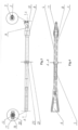
- fig. 1 shows a general view of the lance, example 1
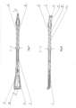
- fig. 2 shows a general view of the lance, example 2
- fig. 3 shows a top view of the lance with the cleaning gas and anti-frosting flow clamps shown along with details presenting the views from the side of the clamps and the side of the dispensing nozzle, example 1
- fig. 4 shows the lance in A-A section along with the coupling to the cleaning gas clamp, example 1
- fig. 5 shows the lance in B-B section along with the gas clamps, example 1
- fig. 6 shows a side view of the lance, example 2
- fig. 7 shows the lance in C-C section, example 2
- fig. 8 shows the lance in D-D section, example 2
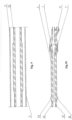
- fig. 9 illustrates the extension in cross section
- fig. 10 shows the body in cross-section.
- the lance of the cleaning kit for medium-voltage power devices is an essential element of the kit equipment.
- the lance example 1, made of a dielectric material, is provided with an external assembly A and an internal assembly B placed therein.
- the external lance assembly A of the cleaning kit for medium-voltage power devices is a head 1 with clamps 2 and 3 of gas connections mounted in it from the front, connected to a body 4, which is detachably connected to an extension 5, which at the opposite end is detachably connected to a dispensing nozzle 6.
- the clamp 2 is connected to the anti-frosting gas connection, while clamp 3 is connected to the cleaning gas connection.
- a flow channel for an anti-frosting gas A' is formed within the external assembly A , and is connected to the anti-frosting gas connection clamp 2, while a sleeve 7, located axially in the body 4, is a cleaning gas flow channel B' and is connected to the cleaning gas clamp 3.
- the head 1 has the form of a solid of revolutions, which central part forms a cylinder 8 with diagonally cut walls 9 and 10, adhering to it at both ends, and the wall 9, from the side of the clamps 2 and 3, is stepped, converging towards the surface on which the clamps 2 and 3 of the connections are installed.
- the head 1 is connected to the body 4, which is in the form of a tube, with the sleeve 7 of the internal assembly B axially mounted therein, connected to the clamp 2 of the cleaning gas connection.
- the sleeve 7 in the cylindrical part of the head 1 is shaped in the form of a bulb, inside which an openwork baffle 11 is installed transversely, acting as a mechanical filter, arresting impurities from the cleaning gas, which is directed from the connection with the clamp 2.
- the sleeve of the body 4 of the external assembly A, from the connection side of the extension 5, has a threading 12 on the inner surface, matching the threading 13 made on the outer surface of the extension 5. Cooperation between these threadings allows to obtain a tight coupling of the extension 5 with the body 4, secured from the outside with a "press-fit" of the outer wall 5' of the extension 5 on the part 14 of the wall of the tube of the body 4 recessed from the outside.
- the tube of the body 4 has a ring 15 secured with a flange 16.
- the same solution, representing the coupling of the body 4 with the extension 5 is located on the opposite side of the extension 5, connecting it with the dispensing nozzle 6.
- the dispensing nozzle 6, connected to the extension 5, has in its initial section the form of a tube which constitutes a continuation of the anti-frosting gas flow channel A' with the sleeve 7 of the cleaning gas flow channel B' located inside.
- the dispensing nozzle widens at a certain distance from the connection point with the extension 5, turning into a flattened solid with diagonally diverging side walls 17, open at the end.
- the flattened surface of the dispensing nozzle 6, example 1 is horizontal to the ground.
- the sleeve 7 of the cleaning gas flow channel B' narrows towards point C, and then widens. Walls 18 of the cleaning gas channel B', tilted to the sides, are placed parallel to the walls 17 of the anti-frosting gas flow channel A'.
- walls 19 and 20 form, in cross-section, closed circuits of the cleaning gas channel B' surrounded by the area of the anti-frosting gas flow channel A'. Keeping the walls of the channels A' and B' at a constant distance is ensured by fastening ribs 21 mounted between the walls 17 and 18.
- An element of the lance equipment is a protective, transparent cover 22, mounted on the body 4, and pressed against the flange 16 with a nut 23.
- the lance is made of a dielectric material and provided with an external assembly A and an internal assembly B placed therein.
- the external assembly A of the lance of the cleaning kit for medium-voltage power devices is a head 1 with clamps 2 and 3 of gas connections mounted in it from the front, connected to a body 4 detachably connected to an extension 5, which at the opposite end is detachably connected to a dispensing nozzle 6.
- the clamp 2 is connected to the anti-frosting gas connection, while the clamp 3 is connected to cleaning gas connection.
- an anti-frosting gas flow channel A' is formed, which is connected to the anti-frosting gas connection clamp 2, while a sleeve 7, located axially in the body 4, is a cleaning gas flow channel B' and is connected to the cleaning gas clamp 3.
- the head 1 has the form of a solid of revolutions, wherein the central part of the head forms a cylinder 8 with diagonally cut walls 9 and 10 adhering to it at both ends, and the wall 9, from the side of the clamps 2 and 3, is stepped, converging towards the surface on which the clamps 2 and 3 of the connections are installed.
- the head 1 is connected to the body 4, which is in the form of a tube, with the sleeve 7 of the internal assembly B axially mounted therein, connected to the clamp 2 of the cleaning gas connection.
- the sleeve 7 in the cylindrical part of the head 1 is shaped in the form of a bulb, inside which an openwork baffle 11 is installed transversely, acting as a mechanical filter arresting impurities from the cleaning gas, which is directed from the connection with the clamp 2.
- the sleeve of the body 4 of the external assembly A, from the connection side of the extension 5, has a threading 12 on the inner surface matching the threading 13 made on the outer surface of the extension 5. Cooperation between these threadings allows to obtain a tight coupling of the extension 5 with the body 4, secured from the outside with a "press-fit" of the outer wall 5' of the extension 5 on the part 14 of the wall of the tube of the body 4 recessed from the outside.
- the tube of the body 4 has a ring 15 secured with a flange 16.
- the same solution, representing the coupling of the body 4 with the extension 5, is on the opposite side, connecting the extension 5 with the dispensing nozzle 6.
- the dispensing nozzle 6, connected with the extension 5, has in its initial section the form of a sleeve which constitutes a continuation of the anti-frosting gas flow channel A' with the sleeve 7 of the cleaning gas flow channel B' located inside, expanding at a certain distance from the connection point with the extension 5. It turns into a flattened solid with diagonally extending side walls 17, open at the end.
- the flattened surface of the dispensing nozzle 6 is angularly bent.
- the sleeve 7 of the cleaning gas flow channel B' narrows towards point C, and then widens. Walls 18 of the cleaning gas channel B', tilted to the sides, are placed parallel to the walls 17 of the anti-frosting gas flow channel A'.
- walls 19 and 20 form, in cross-section, closed circuits of the cleaning gas channel B' surrounded by the area of the anti-frosting gas flow channel A'. Keeping the walls of the channels A' and B' at a constant distance is ensured by fastening ribs 21 mounted between the walls 17 and 18.
- An element of the lance equipment is a protective, transparent cover 22, mounted on the body 4, and pressed against the flange 16 of a nut 23.
Landscapes
- Engineering & Computer Science (AREA)
- Mechanical Engineering (AREA)
- Chemical & Material Sciences (AREA)
- Combustion & Propulsion (AREA)
- General Engineering & Computer Science (AREA)
- Cleaning In General (AREA)
Abstract
Summary of the invention
The invention solves the problem of the construction of a lance of a cleaning kit for medium-voltage power devices.
The lance is equipped with an external assembly (A) and an internal assembly (B) placed therein, wherein the external assembly (A) constitutes a head (1) with clamps (2) and (3) of connections, mounted in it from the front, and connected to a body (4). The body (4) is detachably connected to an extension (5), which at the opposite end is detachably connected to a dispensing nozzle (6).
Description
- The subject of the invention is a lance of a cleaning kit for medium-voltage power devices during cleaning process.
- The solution enables cleaning, mainly of power devices. It can also be used to clean other types of installations.
- From the description of the Polish invention, protected by patent No.
PL238 851 - The presented invention makes it possible to solve a similar technical problem, but due to the fact that it is carried out with the use of fluids, it is not suitable for use in electrical power installations operating under voltage.
- The purpose of the solution, according to the invention, is to eliminate the existing disadvantages by developing the construction of a device enabling the cleaning process of industrial devices, mainly power installations, without the need to disconnect and immobilize them for the time of carrying out cleaning works.
- The implementation of the invention is about developing a solution enabling the achievement of the objective goals, which is the removal of impurities from devices operating under medium voltage.
- The essence of the invention is the construction of a lance, which is an essential component of a cleaning kit for energized power devices. The lance, thanks to the technical means used and the use of suitable raw materials with dielectric properties, allows to carry out the cleaning process of the installation without the necessary to shut it down for the duration of the work. As a result, electrical power devices, despite the work being carried out, can work without interference and perform their functions properly.
- According to the invention, the lance of the cleaning kit for medium-voltage power devices is equipped with an external assembly and an internal assembly located therein.
- The external lance assembly of the cleaning kit, according to the solution, is a head with clamps of technical gas connections mounted in it from the front, connected to a body, detachably connected to an extension, which at the opposite end is connected to a dispensing nozzle.
- A flow channel for an anti-frosting gas is formed within the external assembly and is connected to the anti-frosting gas connection clamp.
- The internal assembly is a sleeve mounted axially in the body. It is a channel for the flow of the cleaning gas. The sleeve is connected to the cleaning gas connection clamp.
- The head has the form of a solid of revolution which central part forms a cylinder with diagonally cut walls, adhering on both sides, the wall from the side of the connection clamp is stepped, converging towards the surface on which they are installed.
- The head is connected to the body formed by a tube with an internal assembly sleeve axially mounted therein and connected to the cleaning gas connection clamp. The sleeve of the internal assembly in the cylindrical part of the head is shaped in the form of a bulb, inside which an openwork baffle is fixed transversely. This baffle acts as a mechanical filter to retain impurities from the gas flowing from the cleaning gas connection.
- The sleeve of the external assembly, at the end, from the connection side of the extension, has a threading on the inside, matching the threading on the outer surface of the tip of the extension. These threadings cooperating with each other create a tight coupling between the extension and the body, secured from the outside with a "press-fit" fastening of the outer wall of the extension on the body, wherein the tube of the body is recessed at the place of attachment.
- Above this recess, there is a ring covered with a flange. The same solution of the connection is placed on the opposite side, creating couplings between the extension and the dispensing nozzle.
- The dispensing nozzle, depending on the needs, capacities and operational requirements, is connected to the extension.
- The dispensing nozzle, in its initial section, near the extension, has the form of a sleeve, which at a certain distance from the place of connection with the extension turns into a flattened solid with side walls diagonally diverging to the sides, open at the end.
- Inside the dispensing nozzle there is a sleeve which constitutes a continuation of the cleaning gas flow channel, converging to the narrowing towards point C, and then widening to the sides, so that its side walls are located parallel to the flared side walls of the dispensing nozzle. The walls of the dispensing nozzle and the axially located cleaning gas channel therein, wherein the walls extend perpendicularly to the flared side walls, form, in cross-section, closed circuits of the cleaning gas channel in the center, surrounded by the anti-frost gas flow channel. Keeping the walls of these channels at a constant distance from each other is ensured by fastening ribs mounted between them.
- An element of the lance equipment is a protective cover, preferably transparent, mounted on the tube of the body, pressed against the flange and fixed with a nut.
- The lance, according to the solution, is light and comfortable to use. Thanks to the appropriate shape and use of the extension, its length can be freely adjusted, adapting to the existing conditions. This makes it possible to clean places and surfaces previously inaccessible. The use of forced gas flow reduces the formation of thermal bridges and, as a result, eliminates frosting.
- The subject of the invention has been illustrated in the attached drawing, in which
fig. 1 shows a general view of the lance, example 1;fig. 2 shows a general view of the lance, example 2;fig. 3 shows a top view of the lance with the cleaning gas and anti-frosting flow clamps shown along with details presenting the views from the side of the clamps and the side of the dispensing nozzle, example 1;fig. 4 shows the lance in A-A section along with the coupling to the cleaning gas clamp, example 1;fig. 5 shows the lance in B-B section along with the gas clamps, example 1;fig. 6 shows a side view of the lance, example 2;fig. 7 shows the lance in C-C section, example 2;fig. 8 shows the lance in D-D section, example 2;fig. 9 illustrates the extension in cross section;fig. 10 shows the body in cross-section. - The lance of the cleaning kit for medium-voltage power devices is an essential element of the kit equipment.
- The lance, example 1, made of a dielectric material, is provided with an external assembly A and an internal assembly B placed therein.
- The external lance assembly A of the cleaning kit for medium-voltage power devices, according to the solution, is a
head 1 withclamps body 4, which is detachably connected to anextension 5, which at the opposite end is detachably connected to a dispensingnozzle 6. - The
clamp 2 is connected to the anti-frosting gas connection, whileclamp 3 is connected to the cleaning gas connection. - A flow channel for an anti-frosting gas A' is formed within the external assembly A, and is connected to the anti-frosting
gas connection clamp 2, while asleeve 7, located axially in thebody 4, is a cleaning gas flow channel B' and is connected to thecleaning gas clamp 3. - The
head 1 has the form of a solid of revolutions, which central part forms acylinder 8 with diagonally cutwalls wall 9, from the side of theclamps clamps - The
head 1 is connected to thebody 4, which is in the form of a tube, with thesleeve 7 of the internal assembly B axially mounted therein, connected to theclamp 2 of the cleaning gas connection. Thesleeve 7 in the cylindrical part of thehead 1 is shaped in the form of a bulb, inside which anopenwork baffle 11 is installed transversely, acting as a mechanical filter, arresting impurities from the cleaning gas, which is directed from the connection with theclamp 2. - The sleeve of the
body 4 of the external assembly A, from the connection side of theextension 5, has athreading 12 on the inner surface, matching the threading 13 made on the outer surface of theextension 5. Cooperation between these threadings allows to obtain a tight coupling of theextension 5 with thebody 4, secured from the outside with a "press-fit" of the outer wall 5' of theextension 5 on thepart 14 of the wall of the tube of thebody 4 recessed from the outside. - Above the
recess 14, the tube of thebody 4 has aring 15 secured with aflange 16. The same solution, representing the coupling of thebody 4 with theextension 5 is located on the opposite side of theextension 5, connecting it with the dispensingnozzle 6. - The dispensing
nozzle 6, connected to theextension 5, has in its initial section the form of a tube which constitutes a continuation of the anti-frosting gas flow channel A' with thesleeve 7 of the cleaning gas flow channel B' located inside. The dispensing nozzle widens at a certain distance from the connection point with theextension 5, turning into a flattened solid with diagonally divergingside walls 17, open at the end. The flattened surface of the dispensingnozzle 6, example 1, is horizontal to the ground. - Located in the dispensing
nozzle 6, thesleeve 7 of the cleaning gas flow channel B' narrows towards point C, and then widens.Walls 18 of the cleaning gas channel B', tilted to the sides, are placed parallel to thewalls 17 of the anti-frosting gas flow channel A'. - Located perpendicularly to the flared
side walls walls ribs 21 mounted between thewalls - An element of the lance equipment, according to the solution, example 1, is a protective,
transparent cover 22, mounted on thebody 4, and pressed against theflange 16 with anut 23. - According to the invention, the lance, example 2, is made of a dielectric material and provided with an external assembly A and an internal assembly B placed therein.
- The external assembly A of the lance of the cleaning kit for medium-voltage power devices, according to the solution, is a
head 1 withclamps body 4 detachably connected to anextension 5, which at the opposite end is detachably connected to a dispensingnozzle 6. - The
clamp 2 is connected to the anti-frosting gas connection, while theclamp 3 is connected to cleaning gas connection. - Inside the external assembly A, an anti-frosting gas flow channel A' is formed, which is connected to the anti-frosting
gas connection clamp 2, while asleeve 7, located axially in thebody 4, is a cleaning gas flow channel B' and is connected to thecleaning gas clamp 3. - The
head 1 has the form of a solid of revolutions, wherein the central part of the head forms acylinder 8 with diagonally cutwalls wall 9, from the side of theclamps clamps - The
head 1 is connected to thebody 4, which is in the form of a tube, with thesleeve 7 of the internal assembly B axially mounted therein, connected to theclamp 2 of the cleaning gas connection. Thesleeve 7 in the cylindrical part of thehead 1 is shaped in the form of a bulb, inside which anopenwork baffle 11 is installed transversely, acting as a mechanical filter arresting impurities from the cleaning gas, which is directed from the connection with theclamp 2. - The sleeve of the
body 4 of the external assembly A, from the connection side of theextension 5, has athreading 12 on the inner surface matching the threading 13 made on the outer surface of theextension 5. Cooperation between these threadings allows to obtain a tight coupling of theextension 5 with thebody 4, secured from the outside with a "press-fit" of the outer wall 5' of theextension 5 on thepart 14 of the wall of the tube of thebody 4 recessed from the outside. - Above the
recess 14, the tube of thebody 4 has aring 15 secured with aflange 16. The same solution, representing the coupling of thebody 4 with theextension 5, is on the opposite side, connecting theextension 5 with the dispensingnozzle 6. - The dispensing
nozzle 6, connected with theextension 5, has in its initial section the form of a sleeve which constitutes a continuation of the anti-frosting gas flow channel A' with thesleeve 7 of the cleaning gas flow channel B' located inside, expanding at a certain distance from the connection point with theextension 5. It turns into a flattened solid with diagonally extendingside walls 17, open at the end. - The flattened surface of the dispensing
nozzle 6, example 2, is angularly bent. - Placed in the dispensing
nozzle 6, thesleeve 7 of the cleaning gas flow channel B' narrows towards point C, and then widens.Walls 18 of the cleaning gas channel B', tilted to the sides, are placed parallel to thewalls 17 of the anti-frosting gas flow channel A'. - Located perpendicularly to the flared
side walls walls ribs 21 mounted between thewalls - An element of the lance equipment, according to the solution, example 2, is a protective,
transparent cover 22, mounted on thebody 4, and pressed against theflange 16 of anut 23.
Claims (7)
- A lance of a cleaning kit for medium-voltage power devices, characterized in that it is equipped with an external assembly (A) and an internal assembly (B) placed therein, wherein the external assembly (A) is a head (1) with clamps (2) and (3) of connections, mounted in it from the front, connected to the body (4) detachably connecting to an extension (5), which at the opposite end is detachably connected to a dispensing nozzle (6); moreover, inside the external assembly (A) there is a an anti-frosting gas flow channel (A'), connected to the clamp (2) of the anti-frosting gas connection, while the sleeve (7) constituting the internal assembly (B) located axially in the body (4) creates a cleaning gas flow channel (B') and is connected to the cleaning gas clamp (3); moreover, the head (1) has the form of a solid of revolutions, and in its cylindrical part, the sleeve (7) is shaped in the form of a bulb, inside which an openwork baffle (11) is installed transversely, while from the side of the connection with the extension (5), on the inner surface of the sleeve of the body (4), there is a threading (12) matching the threading on the outer surface of the tip of the extension (5), creating a tight coupling of the extension (5) with the body (4), secured from the outside with a "press-fit" mounted outer wall (5') of the extension; moreover, the body (4), at the end from the outside, has a recess (14) over which a ring (15) is mounted, secured with a flange (16), while the same recess (14) is located on the outer wall of the dispensing nozzle (6), in the initial section, in the form of a sleeve, and then widening to the sides into the form of a flattened solid with diagonally diverging side walls (17), open at the end, wherein the sleeve of the dispensing nozzle (6) being a section of the gas cleaning channel (B'), narrows and then widens towards point (C), and its flared walls (18) run parallel to the walls (17) of the anti-frosting agent flow channel (A') and together with angularly bent walls (19) and (20) form a closed circuit of the cleaning gas channel (B') surrounded by the area of the anti-frosting agent flow channel (A').
- The lance according to claim 1, characterized in that an element of its equipment is a protective cover (22) mounted on the body (4), and pressed against the flange (16) with a nut (23).
- The lance according to claim 1, characterized in that the clamp (2) is connected to the anti-frosting gas connection, and the clamp (3) is connected to the cleaning gas connection.
- The lance according to claim 1, characterized in that the central part of the head (1) is formed by a cylinder (8) with diagonally cut walls (9) and (10) adhering to it at both ends, wherein the wall (9), from the side of the clamps (2) and (3) is stepped, converging towards the surface with the anti-frosting gas connection clamp (2) and the cleaning gas clamp (3) installed thereon.
- The lance according to claim 1, characterized in that an openwork baffle (11) is a mechanical filter of impurities in the cleaning gas.
- The lance according to claim 1, characterized in that it is made of a dielectric material.
- The lance according to claim 1, characterized in that the dispensing nozzle (6) at the end is parallel to the ground or angularly bent.
Applications Claiming Priority (1)
| Application Number | Priority Date | Filing Date | Title |
|---|---|---|---|
| PL442523A PL245918B1 (en) | 2022-10-13 | 2022-10-13 | Lance of the cleaning kit for medium voltage power equipment |
Publications (1)
| Publication Number | Publication Date |
|---|---|
| EP4417328A1 true EP4417328A1 (en) | 2024-08-21 |
Family
ID=88287289
Family Applications (1)
| Application Number | Title | Priority Date | Filing Date |
|---|---|---|---|
| EP23199745.3A Pending EP4417328A1 (en) | 2022-10-13 | 2023-09-26 | Lance of a cleaning kit for medium-voltage power devices |
Country Status (2)
| Country | Link |
|---|---|
| EP (1) | EP4417328A1 (en) |
| PL (1) | PL245918B1 (en) |
Citations (5)
| Publication number | Priority date | Publication date | Assignee | Title |
|---|---|---|---|---|
| PL238851A1 (en) | 1982-11-02 | 1984-05-21 | Maszyn Rolniczych Agromet Inof | Furnace for galvanizing steel and cast iron ware |
| US6176437B1 (en) * | 1993-10-15 | 2001-01-23 | Mona Skannerup | Blast gun for compressed air |
| US20090101183A1 (en) * | 2007-10-22 | 2009-04-23 | Sk Energy Co., Ltd. | Apparatus for cleaning tube fins of air fan cooler for heat exchanger |
| WO2013060794A1 (en) * | 2011-10-28 | 2013-05-02 | Bendel Werkzeuge Inh. Frank Bendel | Spray nozzle assembly for compressed air-operated cleaning devices |
| US20160332175A1 (en) * | 2015-02-17 | 2016-11-17 | Neutek International Inc. | Gyrating nozzle spray gun |
Family Cites Families (3)
| Publication number | Priority date | Publication date | Assignee | Title |
|---|---|---|---|---|
| US4220170A (en) * | 1979-07-30 | 1980-09-02 | Hebert Chris J | Apparatus for cleaning large tank interiors |
| US4841999A (en) * | 1987-08-21 | 1989-06-27 | Donald Danko | Brake durm cleaner assembly and method of cleaning |
| DE202009018911U1 (en) * | 2009-02-16 | 2014-07-08 | Jens-Werner Kipp | Cleaning device for cleaning sensitive surfaces |
-
2022
- 2022-10-13 PL PL442523A patent/PL245918B1/en unknown
-
2023
- 2023-09-26 EP EP23199745.3A patent/EP4417328A1/en active Pending
Patent Citations (5)
| Publication number | Priority date | Publication date | Assignee | Title |
|---|---|---|---|---|
| PL238851A1 (en) | 1982-11-02 | 1984-05-21 | Maszyn Rolniczych Agromet Inof | Furnace for galvanizing steel and cast iron ware |
| US6176437B1 (en) * | 1993-10-15 | 2001-01-23 | Mona Skannerup | Blast gun for compressed air |
| US20090101183A1 (en) * | 2007-10-22 | 2009-04-23 | Sk Energy Co., Ltd. | Apparatus for cleaning tube fins of air fan cooler for heat exchanger |
| WO2013060794A1 (en) * | 2011-10-28 | 2013-05-02 | Bendel Werkzeuge Inh. Frank Bendel | Spray nozzle assembly for compressed air-operated cleaning devices |
| US20160332175A1 (en) * | 2015-02-17 | 2016-11-17 | Neutek International Inc. | Gyrating nozzle spray gun |
Also Published As
| Publication number | Publication date |
|---|---|
| PL442523A1 (en) | 2024-04-15 |
| PL245918B1 (en) | 2024-10-28 |
Similar Documents
| Publication | Publication Date | Title |
|---|---|---|
| US4340365A (en) | Spraying and suction cleansing device | |
| CA2298920C (en) | Tank cleaning apparatus | |
| US20240123473A1 (en) | Lance of a cleaning kit for medium-voltage power devices | |
| US4314580A (en) | Faucet structure | |
| US2201080A (en) | Pressure cleaning apparatus | |
| EP4417328A1 (en) | Lance of a cleaning kit for medium-voltage power devices | |
| CA2907497C (en) | Condensate drain clearing device and method | |
| WO2002059538A8 (en) | Method and apparatus for cleaning the tubes of a tubular heat exchanger | |
| US2221803A (en) | Radiator cleaning device | |
| US4240473A (en) | Insert for injecting a liquid product into a bore | |
| US3922753A (en) | Compressed air cleaning tool | |
| US1273656A (en) | Strainer. | |
| USRE29546E (en) | Drip level irrigation | |
| US4722127A (en) | Method of servicing condensate line of an air conditioner | |
| US4006508A (en) | Manual radiator rodder | |
| DE59708099D1 (en) | Manual spray gun for a high pressure cleaning device | |
| KR20170043804A (en) | Spare fin removal device | |
| RU2011138724A (en) | GLASS COOKING COOLING SYSTEM SUPPLIED WITH A LIQUID CARBON ACID REMOVER | |
| RU93057113A (en) | LOCKING DEVICE | |
| JP6543804B2 (en) | Heat exchanger and water heater using the same | |
| EP0814296A2 (en) | Freezing device for pipes filled with fluid | |
| US2425277A (en) | Trocar | |
| CN121739221A (en) | Device and method for collecting oil liquid by disassembling conduit joint | |
| PL245808B1 (en) | Nozzle for cleaning devices and power, electrical and electronic installations under low voltage up to 1 kV | |
| JP2004028813A (en) | Liquid measuring device |
Legal Events
| Date | Code | Title | Description |
|---|---|---|---|
| PUAI | Public reference made under article 153(3) epc to a published international application that has entered the european phase |
Free format text: ORIGINAL CODE: 0009012 |
|
| STAA | Information on the status of an ep patent application or granted ep patent |
Free format text: STATUS: REQUEST FOR EXAMINATION WAS MADE |
|
| 17P | Request for examination filed |
Effective date: 20230926 |
|
| AK | Designated contracting states |
Kind code of ref document: A1 Designated state(s): AL AT BE BG CH CY CZ DE DK EE ES FI FR GB GR HR HU IE IS IT LI LT LU LV MC ME MK MT NL NO PL PT RO RS SE SI SK SM TR |