EP4417172A1 - Wearing article and method of manufacturing same - Google Patents
Wearing article and method of manufacturing same Download PDFInfo
- Publication number
- EP4417172A1 EP4417172A1 EP22895256.0A EP22895256A EP4417172A1 EP 4417172 A1 EP4417172 A1 EP 4417172A1 EP 22895256 A EP22895256 A EP 22895256A EP 4417172 A1 EP4417172 A1 EP 4417172A1
- Authority
- EP
- European Patent Office
- Prior art keywords
- absorbent body
- girth member
- end edge
- continuous body
- absorbent
- Prior art date
- Legal status (The legal status is an assumption and is not a legal conclusion. Google has not performed a legal analysis and makes no representation as to the accuracy of the status listed.)
- Pending
Links
Images



Classifications
-
- A—HUMAN NECESSITIES
- A61—MEDICAL OR VETERINARY SCIENCE; HYGIENE
- A61F—FILTERS IMPLANTABLE INTO BLOOD VESSELS; PROSTHESES; DEVICES PROVIDING PATENCY TO, OR PREVENTING COLLAPSING OF, TUBULAR STRUCTURES OF THE BODY, e.g. STENTS; ORTHOPAEDIC, NURSING OR CONTRACEPTIVE DEVICES; FOMENTATION; TREATMENT OR PROTECTION OF EYES OR EARS; BANDAGES, DRESSINGS OR ABSORBENT PADS; FIRST-AID KITS
- A61F13/00—Bandages or dressings; Absorbent pads
- A61F13/15—Absorbent pads, e.g. sanitary towels, swabs or tampons for external or internal application to the body; Supporting or fastening means therefor; Tampon applicators
- A61F13/15577—Apparatus or processes for manufacturing
- A61F13/15707—Mechanical treatment, e.g. notching, twisting, compressing, shaping
- A61F13/15723—Partitioning batts; Cutting
-
- A—HUMAN NECESSITIES
- A61—MEDICAL OR VETERINARY SCIENCE; HYGIENE
- A61F—FILTERS IMPLANTABLE INTO BLOOD VESSELS; PROSTHESES; DEVICES PROVIDING PATENCY TO, OR PREVENTING COLLAPSING OF, TUBULAR STRUCTURES OF THE BODY, e.g. STENTS; ORTHOPAEDIC, NURSING OR CONTRACEPTIVE DEVICES; FOMENTATION; TREATMENT OR PROTECTION OF EYES OR EARS; BANDAGES, DRESSINGS OR ABSORBENT PADS; FIRST-AID KITS
- A61F13/00—Bandages or dressings; Absorbent pads
- A61F13/15—Absorbent pads, e.g. sanitary towels, swabs or tampons for external or internal application to the body; Supporting or fastening means therefor; Tampon applicators
- A61F13/15577—Apparatus or processes for manufacturing
- A61F13/15756—Applying tabs, strips, tapes, loops; Knotting the ends of pads
-
- A—HUMAN NECESSITIES
- A61—MEDICAL OR VETERINARY SCIENCE; HYGIENE
- A61F—FILTERS IMPLANTABLE INTO BLOOD VESSELS; PROSTHESES; DEVICES PROVIDING PATENCY TO, OR PREVENTING COLLAPSING OF, TUBULAR STRUCTURES OF THE BODY, e.g. STENTS; ORTHOPAEDIC, NURSING OR CONTRACEPTIVE DEVICES; FOMENTATION; TREATMENT OR PROTECTION OF EYES OR EARS; BANDAGES, DRESSINGS OR ABSORBENT PADS; FIRST-AID KITS
- A61F13/00—Bandages or dressings; Absorbent pads
- A61F13/15—Absorbent pads, e.g. sanitary towels, swabs or tampons for external or internal application to the body; Supporting or fastening means therefor; Tampon applicators
- A61F13/15577—Apparatus or processes for manufacturing
- A61F13/15804—Plant, e.g. involving several steps
-
- A—HUMAN NECESSITIES
- A61—MEDICAL OR VETERINARY SCIENCE; HYGIENE
- A61F—FILTERS IMPLANTABLE INTO BLOOD VESSELS; PROSTHESES; DEVICES PROVIDING PATENCY TO, OR PREVENTING COLLAPSING OF, TUBULAR STRUCTURES OF THE BODY, e.g. STENTS; ORTHOPAEDIC, NURSING OR CONTRACEPTIVE DEVICES; FOMENTATION; TREATMENT OR PROTECTION OF EYES OR EARS; BANDAGES, DRESSINGS OR ABSORBENT PADS; FIRST-AID KITS
- A61F13/00—Bandages or dressings; Absorbent pads
- A61F13/15—Absorbent pads, e.g. sanitary towels, swabs or tampons for external or internal application to the body; Supporting or fastening means therefor; Tampon applicators
- A61F13/45—Absorbent pads, e.g. sanitary towels, swabs or tampons for external or internal application to the body; Supporting or fastening means therefor; Tampon applicators characterised by the shape
- A61F13/49—Absorbent pads, e.g. sanitary towels, swabs or tampons for external or internal application to the body; Supporting or fastening means therefor; Tampon applicators characterised by the shape specially adapted to be worn around the waist, e.g. diapers, nappies
- A61F13/493—Absorbent pads, e.g. sanitary towels, swabs or tampons for external or internal application to the body; Supporting or fastening means therefor; Tampon applicators characterised by the shape specially adapted to be worn around the waist, e.g. diapers, nappies adjustable by adding or removing material, e.g. umbilical cord arrangements
-
- A—HUMAN NECESSITIES
- A61—MEDICAL OR VETERINARY SCIENCE; HYGIENE
- A61F—FILTERS IMPLANTABLE INTO BLOOD VESSELS; PROSTHESES; DEVICES PROVIDING PATENCY TO, OR PREVENTING COLLAPSING OF, TUBULAR STRUCTURES OF THE BODY, e.g. STENTS; ORTHOPAEDIC, NURSING OR CONTRACEPTIVE DEVICES; FOMENTATION; TREATMENT OR PROTECTION OF EYES OR EARS; BANDAGES, DRESSINGS OR ABSORBENT PADS; FIRST-AID KITS
- A61F13/00—Bandages or dressings; Absorbent pads
- A61F13/15—Absorbent pads, e.g. sanitary towels, swabs or tampons for external or internal application to the body; Supporting or fastening means therefor; Tampon applicators
- A61F13/53—Absorbent pads, e.g. sanitary towels, swabs or tampons for external or internal application to the body; Supporting or fastening means therefor; Tampon applicators characterised by the absorbing medium
- A61F13/539—Absorbent pads, e.g. sanitary towels, swabs or tampons for external or internal application to the body; Supporting or fastening means therefor; Tampon applicators characterised by the absorbing medium characterised by the connection of the absorbent layers with each other or with the outer layers
-
- A—HUMAN NECESSITIES
- A61—MEDICAL OR VETERINARY SCIENCE; HYGIENE
- A61F—FILTERS IMPLANTABLE INTO BLOOD VESSELS; PROSTHESES; DEVICES PROVIDING PATENCY TO, OR PREVENTING COLLAPSING OF, TUBULAR STRUCTURES OF THE BODY, e.g. STENTS; ORTHOPAEDIC, NURSING OR CONTRACEPTIVE DEVICES; FOMENTATION; TREATMENT OR PROTECTION OF EYES OR EARS; BANDAGES, DRESSINGS OR ABSORBENT PADS; FIRST-AID KITS
- A61F13/00—Bandages or dressings; Absorbent pads
- A61F13/15—Absorbent pads, e.g. sanitary towels, swabs or tampons for external or internal application to the body; Supporting or fastening means therefor; Tampon applicators
- A61F13/56—Supporting or fastening means
Definitions
- the present invention relates to a wearing article and a method of manufacturing the same, and more particularly to a wearing article with a concave peripheral edge on the front side and a method of manufacturing the same.
- a wearing article for a newborn baby with a concave peripheral edge on the front side has been proposed so as not to touch the navel of the newborn baby whose umbilical cord has just been cut.
- an absorbent body 103 is disposed between a water-permeable top sheet 101 and a water-impermeable back sheet 102 so as to cross the crotch region 108.
- Flap portions 104 and 105 are formed by front and back sheets 101 and 102 extending outward from the outer peripheral edge of absorbent body 103.
- a fastening piece 110 having a pressure-sensitive adhesive surface is attached to the flap portion 104 of the dorsal side region 107.
- a recessed part 111 is formed in a front region 106 located on the front side of the wearer, and a protrusion 112 is formed in a dorsal side region 107 located on the rear side of the wearer (see, for example, Patent Literature 1).
- FIG. 5 is a plan view showing another wearing article 199 in a developed state.
- this wearing article 199 has ears 220, 222, 230, 232 joined between a back sheet 213 and a top sheet 215 so as to protrude from longitudinal edge parts 116, 117.
- the front terminal edge part 140 of the front section which is located on the front side of the wearer, has a U-shaped cutout part 142.
- the rear terminal edge part 150 disposed on the rear side of the wearer has a U-shaped protruding cut portion 152 (see, for example, Patent Literature 2).
- These wearing articles are made by cutting a continuous body in which multiple regions where the wearing article is planned to be formed are connected in a direction connecting the front part placed on the ventral side of the wearer and the rear part placed on the dorsal side of the wearer, and by doing so, corresponding contour shapes are formed in the front part and the rear part. Therefore, if a concave peripheral edge is formed in the front part, the peripheral edge of the rear part is formed in a convex shape, and the convex part may come into contact with the back, giving a sense of discomfort. Furthermore, if the peripheral edge of the rear portion of the wearing article is formed in a convex or concave shape, the external shape becomes complicated, making it difficult to package the wearing article compactly.
- the problem to be solved by the present invention is to provide a wearing article with which it is possible to form a concave shape in a portion positioned on the ventral side without forming a convex shape or a concave shape on the peripheral edge of the portion positioned on the dorsal side, and improve wearing comfort and appearance, and a method of manufacturing the same.
- the present invention provides a wearing article configured as follows.
- the wearing article is provided with (a) a girth member having a pair of side edges extending in a first direction, (b) an absorbent body having a pair of end edges facing each other, and in which a cutout part is formed in the intermediate portion of one end edge thereof, the absorbent body being joined to the girth member so that the other end edge overlaps with the girth member and the intermediate portion between the one end edge and the other end edge overlaps with one of the side edges of the girth member, and (c) fastening members enabling both end parts in the first direction of the girth member to repeatedly fasten to and separate from a portion of the absorbent body adjacent to the one end edge, wherein a portion of the girth member adjacent to the other side edge is folded back so as to cover the other end edge of the absorbent body.
- a concave shape can be formed in the portion disposed on the ventral side by the cutout part on one end edge of the absorbent body. Since the girth member is folded back, no convex or concave shape is formed on the circumference of the dorsal side of the wearing article. Since the other end edge of the absorbent body and its vicinity are covered by the folded portion of the girth member, it is possible to improve the wearing comfort, keep the exterior simple, keep the beauty, and improve the appearance.
- another cutout part is formed in an intermediate portion of the other end edge of the absorbent body.
- a portion of the girth member adjacent to the other side edge is folded back so as to cover the other cutout part.
- the cutout part on one end edge of the absorbent body that is exposed to the outside can be formed with high accuracy, and a cutout part having a desired shape can be formed efficiently. Even if another cutout part is formed on the other end edge of the absorbent body, the other end edge of the absorbent body and its vicinity are covered by the folded portion of the girth member, so that the other cutout part can be made invisible. Therefore, it is possible to keep the wearing comfort intact, keep the exterior simple, maintain beauty, and improve the appearance.
- the present invention provides a method of manufacturing a wearing article configured as follows.
- the method of manufacturing a wearing article comprises
- a concave shape can be formed in the portion disposed on the ventral side by the cutout part on one end edge of the absorbent body. Since the girth member is folded back and no convex or concave shape is formed on the dorsal side periphery of the wearing article, the exterior can be kept simple and beauty can be maintained.
- the cutout part of the absorbent body can be formed with high precision, and a cutout part having a desired shape can be efficiently formed.
- a through hole is formed in the absorbent body continuous body so as to cross an intermediate portion of the boundary line of the second region of the absorbent body continuous body, and then, the absorbent body continuous body is cut along the boundary line, to form the absorbent body.
- the through hole forms a cutout part in one end edge of the absorbent body.
- it is easy to form a cutout part with high precision, and a cutout part having a desired shape can be efficiently formed.
- a concave shape can be formed in a portion placed on the ventral side without forming or exposing a convex or concave shape on the periphery of a portion placed on the dorsal side, which can improve the wearing comfort and appearance.
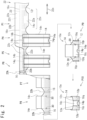
- FIG. 1(a) is a schematic view showing the developed state of the wearing article 10, and shows the skin side that comes into contact with the wearer's skin.
- FIG. 1(b) is a schematic view showing the wearing article 10 in a folded state.
- the wearing article 10 generally includes a girth member 12, an absorbent body 14, and fastening members 16a, 16b, and 16c.
- the absorbent body 14 is formed into a substantially rectangular shape, and has a pair of end edges 14a, 14b facing each other, and a pair of side edges 14m, 14n facing each other.
- a cutout part 14p is formed in the intermediate portion of one end edge 14a.
- another cutout part 14q is formed in the intermediate portion of the other end edge 14b.
- a configuration in which the other cutout part 14q is not formed may also be used.
- the depth of the cutout part 14p on one end edge 14a is preferably greater than the depth of the cutout part 14q on the other end edge 14b.
- the end edges 14a, 14b and the side edges 14m, 14n may be straight or curved.
- the girth member 12 has a pair of side edges 12a and 12b extending in a first direction 12x indicated by an arrow 12x, and a portion 12c adjacent to the other side edge 12b is folded back.
- cutout parts 12r are formed on both sides of one side edge 12a of the girth member 12, but the cutout parts 12r may not be formed.
- the absorbent body 14 is joined to the girth member 12 in a T-shape. That is, the absorbent body 14 is joined to the girth member 12 so that the other end edge 14b of the absorbent body 14 overlaps with the girth member 12, and the intermediate portion between one end edge 14a and the other end edge 14b of the absorbent body 14 overlaps with one side edge 12a of the girth members 12.
- a portion 12c of the girth member 12 adjacent to the other side edge 12b is folded back along the fold line 12k so as to cover the other end edge 14b of the absorbent body 14 and the cutout part 14q.
- the fold line 12k and the side edges 12a, 12b of the girth member 12 are parallel to each other.
- the folded portion 12c of the girth member 12 may be joined to another portion of the girth member 12, or may be joined to the absorbent body 14.
- the other end edge 14b of the absorbent body 14 and its vicinity are covered by the folded portion 12c of the girth member 12, which can improve the wearing comfort and appearance. That is, since the other end edge 14b and the cutout part 14q of the absorbent body 14 do not touch the wearer's skin, discomfort can be reduced or eliminated.
- the folded portion 12c of the girth member 12 touches the wearer's skin, the skin touch can be improved. Since the cutout part 14q of the other end edge 14b of the absorbent body 14 is not exposed, the exterior can be kept simple, beauty can be maintained, and the appearance can be improved.
- the absorbent body 14 has a core 15k containing pulp or the like for absorbing liquid etc. disposed between a liquid-permeable sheet 15a placed on the skin side and a liquid-impermeable sheet 15b placed on the non-skin side.
- Three-dimensional gathers 15s are provided on the skin side of the absorbent body 14.
- the three-dimensional gathers 15s are configured, for example, to stand up when the absorbent body 14 is curved so that the side edges 14m and 14n of the absorbent body 14 are curved so that the skin side of the absorbent body 14 becomes concave.
- leg gathers 15t are provided along side edges 14m and 14n of the absorbent body 14.
- a fastening member 16c is fixed to a portion adjacent to one end edge 14a of the absorbent body 14 so as to be exposed on the non-skin side.
- the girth member 12 has stretchability in the first direction 12x.
- the girth member 12 is, for example, a stretchable composite member in which a plurality of two types of elastic stretchable members 13a, 13b with different characteristics are arranged between two nonwoven fabric sheets 11s, 11t so as to extend in the first direction 12x, and while the elastic stretchable members 13a, 13b are stretched, appropriate locations of the elastic stretchable members 13a, 13b and the nonwoven fabric sheets 11s, 11t are joined to each other.
- the elastic stretchable members 13a, 13b may be of one type, two or more types, or may be singular.
- thread rubber, a resin sheet having stretchability, or the like is used for the elastic stretchable members 13a and 13b.
- the elastic stretchable members 13a and 13b are stretched, and the wrinkles of the nonwoven fabric sheets 11s and 11t are stretched to smooth, and when the stretching is stopped, the member contracts.
- Fastening members 16a and 16b are fixed to end parts 12m and 12n of the girth member 12 on both sides in the first direction 12x.
- the fastening members 16a, 16b may be fixed at an interval from the end edges 12i, 12j on both sides of the girth member 12 in the first direction 12x, or may be fixed so as to overlap with the end edges 12i, 12j.
- the fastening members 16a and 16b may be fixed so as to protrude from the girth member 12 beyond the end edges 12i and 12j, or may be fixed in a folded state.
- hook-and-loop fasteners are used for the fastening members 16a, 16b; 16c.
- the fastening members 16a and 16b fixed to the girth member 12 are first members 16a and 16b of hook-and-loop fasteners having hook surfaces raised in a hook shape, and are fixed so that the hook surfaces are exposed on the skin side.
- the fastening member 16c fixed to the absorbent body 14 is a second member 16c of a hook-and-loop fastener having a loop surface that is densely brushed in a loop shape, and is fixed so that the loop surface is exposed on the non-skin side.
- the hook surfaces of the fastening members 16a and 16b fixed to the girth member 12 and the loop surface of the fastening member 16c fixed to the absorbent body 14 can be removably adhered to each other, and adhesion and separation thereof can be repeated.
- the wearing article 10 can be folded and brought into a fastened state in which the girth member 12 is fastened to the absorbent body 14. That is, in the developed state shown in FIG. 1(a) , the absorbent body 14 is folded back so that a portion 14x on one end edge 14a side of the absorbent body 14 overlaps with the other end edge 14b side of the absorbent body 14 and the folded-back portion 12c of the girth member 12. Next, as shown in FIG.
- the flap portions 12p and 12q on both sides of the girth member 12 in the first direction 12x are folded back and overlapped on the non-skin surface side of the folded portion 14x of the absorbent body 14, and the fastening members 16a and 16b fixed to the girth member 12 are fastened to the fastening member 16c fixed to absorbent body 14. Thereby, the wearing article 10 is brought into a fastened state.
- the fastening members 16a, 16b; 16c are members which make it possible that the end parts 12m, 12n on both sides of the girth member 12 in the first direction 12x are repeatedly fastened to and separated from the portion adjacent to one end edge 14a of the absorbent body 14.
- the fastening members 16a, 16b; 16c can be fixed to only one of the girth member 12 and the absorbent body 14, it is preferable to fix them to at least the girth member 12. It is also possible to use removable adhesive tape or the like for the fastening members 16a, 16b; 16c.
- the wearing article 10 may be provided in the developed state shown in FIG. 1(a) or in the fastened state shown in FIG. 1(b) .
- the wearing article 10 is developed without releasing the fastening, to form a girth opening surrounded by the fold line 12k of the girth member 12 and two underbody openings surrounded by one side edge 12a and the cutout part 12r of the girth member 12 and the side edges 14m and 14n of the absorbent body 14, and both legs are passed from the girth opening to the underbody opening similarly to a pants-type diaper, thereby the wearing article 10 can be worn.
- the wearing article 10 can also be worn similar to a tape-type diaper in the developed state as shown in FIG. 1(a) by releasing the fastening.
- the wearing article 10 is worn with one end edge 14a of the absorbent body 14 placed in front of the wearer, and the girth member 12 wrapped around the wearer. At this condition, the cutout part 14p of one end edge 14a of the absorbent body 14 is placed at a position away from the wearer's navel, and the wearing article 10 can be aligned with respect to the navel so as not to touch the wound after cutting the umbilical cord.
- the wearing article 10 can be unfastened and refastened after being worn, it is easy to accurately position the wearing article 10 with respect to the navel. Further, it is easy to adjust the girth fastening extent or the like, and to confirm whether or not the wearing article 10 needs to be replaced.
- the wearing article 10 can form a concave shape in the portion disposed on the ventral side by the cutout part 14p of the one end edge 14a of the absorbent body 14.
- the wearing article 10 since the fold line 12k of the girth member 12 becomes the periphery of the portion disposed on the dorsal side, no convex shape or concave shape is formed on the periphery of the portion disposed on the dorsal side. Therefore, the wearing article 10 can be easily packaged compactly.
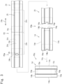
- FIG. 2 is a schematic view of the manufacturing process of the wearing article 10.
- FIG. 3 is a schematic view of the manufacturing process of the absorbent body 14.
- a through hole 26 is formed in the absorbent body continuous body 24 so as to cross the intermediate portion of the boundary line 24k of the second region 24v of the absorbent body continuous body 24, as shown by a reference numeral P3a, and then the absorbent body continuous body 24 is cut linearly along the boundary line 24k, to form a substantially rectangular absorbent body 14 having end edges 14a, 14b and side edges 14m, 14n, as shown by a reference numeral P3b.
- the cutout part 14p of one end edge 14a of the absorbent body 14 is formed by the through hole 26.
- the through hole 26 also forms a cutout part 14q on the other end edge 14b of the absorbent body 14.
- the absorbent body continuous body 24 may be cut along a curved cutting line, so as to form a cutout part 14p on one end edge 14a of the absorbent body 14 simultaneously with the cutting of the absorbent body continuous body 24, although not shown.
- a convex portion corresponding to the contour shape of the cutout part 14p on one end edge 14a of the absorbent body 14 is formed on the other end edge 14b of the absorbent body 14, and this convex portion is covered by a portion 22c adjacent to the other side edge 22b of the girth member continuous body 22 by a folding back process P5 to be described later.
- the absorbent body cutting process it is also possible to form the through holes 26 and cut the absorbent body continuous body 24 at the same time.
- the stress distribution generated in the absorbent body continuous body 24 during processing becomes simple, as compared with a case of cutting the absorbent body continuous body 24 along the curved cutting line to form a cutout part 14p simultaneously with the cutting of the absorbent body continuous body 24, a case of effecting formation of a through hole 26 and cutting of the absorbent body continuous body 24 simultaneously, and the like. Therefore, it is easy to form the cutout part 14p with high accuracy, the absorbent body continuous body 24 can be conveyed at high speed to form the absorbent body 14, and the cutout part 14p having a desired shape can be efficiently formed.
- the absorbent body continuous body 24 is conveyed in the second direction 24x, and, as shown by a reference numeral P3c in FIG. 3 , the direction of the cut absorbent body 14 is rotated by 90 degrees with respect to the conveying direction 14y of the absorbent body 14, and then supplied to the subsequent process.
- a plurality of absorbent bodies 14 are joined to the girth member continuous body 22 at intervals with each other in the first direction 22x so that the other end edge 14b of the absorbent body 14 overlaps with the girth member continuous body 22, and the intermediate portion between the one end edge 14a and the other end edge 14b of the absorbent body 14 overlaps with one side edge 22a of the girth member continuous body 22.
- This is an absorbent body joining process P4.
- the absorbent body 14 is joined to the girth member continuous body 22 by ultrasonic sealing or heat sealing. It is also possible to join the absorbent body 14 to the girth member continuous body 22 using an adhesive.
- a first member having a hook surface of a hook-and-loop fastener is used for the fastening member 16, and fixed to the girth member continuous body 22 in a state where it crosses the planned cutting position 22k of the girth member continuous body 22 indicated by a chain line 22k and the hook surface is exposed.
- the fastening member 16 is a member (16p 16q) that allows the end parts 12m and 12n of the girth member 12 to be repeatedly fastened to and separated from a portion adjacent to one end edge 14a of the absorbent body 14 (i.e., the fastening member 16c).
- the girth member continuous body 22 and the other end edge 14b side of the absorbent body 14 are folded back, to fold the absorbent body 14 in half, and allowed to overlap with the one end edge 14a side of the absorbent body 14 so that the girth member continuous body 22 covers the one end edge 14a side of the body 14.
- the one end edge 14a side of the absorbent body 14 may be folded back, to fold the absorbent body 14 in half, and allowed to overlap with the other end edge 14b side of the absorbent body 14 so that the girth member continuous body 22 is covered by the one end edge 14a side of the body 14.
- the girth member continuous body 22 in which the portion 22c adjacent to the other side edge 22b is folded back, is cut at the planned cutting position 22k, to form a girth member 12 having end parts 12m and 12n on both sides of the first direction 22x.
- This is a girth member cutting process P9.
- the fastening member 16 is also cut, and the fastening member 16 is divided into two fastening members 16p and 16q.
- the girth member cutting process P9 individual pieces of the wearing article 10a are formed.
- the fastening member fixing process P6 after fixing the fastening members 16a and 16b on both sides of the planned cutting position 22k with an interval from the planned cutting position 22k, the girth member continuous body 22 is cut at the planned cutting position 22k, thereby a wearing article 10 can be formed in which the fastening members 16a and 16b are fixed apart from the end edges 12i and 12j of the girth member 12, as shown in FIG. 1(a) .
- the fastening member 16 can also be fixed to the girth member continuous body 22 before the portion 22c adjacent to the other side edge 22b of the girth member continuous body 22 is folded back. Moreover, it is also possible to fix the fastening members 16a and 16b to the girth member 12 after cutting. That is, in the fastening member fixing process, the fastening members 16; 16a, 16b are fixed to the girth member continuous body 22 or the girth member 12.
- a concave cutout part 14p can be formed on the portion disposed on the ventral side without forming a convex or concave shape on the peripheral edge 12k of the portion disposed on the dorsal side, and wearing comfort and appearance can be improved.
- the wearing article of the present invention can be manufactured in a variety of ways.
- the wearing articles 10 and 10a can also be manufactured by cutting the girth member continuous body 22 to form the girth member 12 without folding-back the portion 22c adjacent to the other side edge 22b of the girth member continuous body 22, and by folding-back the portion 12c adjacent to the other side edge 12b of the girth member 12.
Landscapes
- Health & Medical Sciences (AREA)
- Engineering & Computer Science (AREA)
- Life Sciences & Earth Sciences (AREA)
- Biomedical Technology (AREA)
- Heart & Thoracic Surgery (AREA)
- Vascular Medicine (AREA)
- Epidemiology (AREA)
- Animal Behavior & Ethology (AREA)
- General Health & Medical Sciences (AREA)
- Public Health (AREA)
- Veterinary Medicine (AREA)
- Manufacturing & Machinery (AREA)
- Botany (AREA)
- Mechanical Engineering (AREA)
- Absorbent Articles And Supports Therefor (AREA)
Abstract
Description
- The present invention relates to a wearing article and a method of manufacturing the same, and more particularly to a wearing article with a concave peripheral edge on the front side and a method of manufacturing the same.
- A wearing article for a newborn baby with a concave peripheral edge on the front side has been proposed so as not to touch the navel of the newborn baby whose umbilical cord has just been cut.
- For example, in a wearing article shown in a developed view of
FIG. 4 , anabsorbent body 103 is disposed between a water-permeabletop sheet 101 and a water-impermeable back sheet 102 so as to cross thecrotch region 108.Flap portions back sheets absorbent body 103. Afastening piece 110 having a pressure-sensitive adhesive surface is attached to theflap portion 104 of thedorsal side region 107. Arecessed part 111 is formed in afront region 106 located on the front side of the wearer, and aprotrusion 112 is formed in adorsal side region 107 located on the rear side of the wearer (see, for example, Patent Literature 1). -
FIG. 5 is a plan view showing another wearingarticle 199 in a developed state. As shown inFIG. 5 , this wearingarticle 199 hasears back sheet 213 and atop sheet 215 so as to protrude fromlongitudinal edge parts 116, 117. The frontterminal edge part 140 of the front section, which is located on the front side of the wearer, has aU-shaped cutout part 142. The rearterminal edge part 150 disposed on the rear side of the wearer has a U-shaped protruding cut portion 152 (see, for example, Patent Literature 2). -
- [Patent Literature 1]
JP 62-136505 U1 - [Patent Literature 2]
JP 4932738 B2 - These wearing articles are made by cutting a continuous body in which multiple regions where the wearing article is planned to be formed are connected in a direction connecting the front part placed on the ventral side of the wearer and the rear part placed on the dorsal side of the wearer, and by doing so, corresponding contour shapes are formed in the front part and the rear part. Therefore, if a concave peripheral edge is formed in the front part, the peripheral edge of the rear part is formed in a convex shape, and the convex part may come into contact with the back, giving a sense of discomfort. Furthermore, if the peripheral edge of the rear portion of the wearing article is formed in a convex or concave shape, the external shape becomes complicated, making it difficult to package the wearing article compactly.
- In view of these circumstances, the problem to be solved by the present invention is to provide a wearing article with which it is possible to form a concave shape in a portion positioned on the ventral side without forming a convex shape or a concave shape on the peripheral edge of the portion positioned on the dorsal side, and improve wearing comfort and appearance, and a method of manufacturing the same.
- In order to solve the above problems, the present invention provides a wearing article configured as follows.
- The wearing article is provided with (a) a girth member having a pair of side edges extending in a first direction, (b) an absorbent body having a pair of end edges facing each other, and in which a cutout part is formed in the intermediate portion of one end edge thereof, the absorbent body being joined to the girth member so that the other end edge overlaps with the girth member and the intermediate portion between the one end edge and the other end edge overlaps with one of the side edges of the girth member, and (c) fastening members enabling both end parts in the first direction of the girth member to repeatedly fasten to and separate from a portion of the absorbent body adjacent to the one end edge, wherein a portion of the girth member adjacent to the other side edge is folded back so as to cover the other end edge of the absorbent body.
- According to the above configuration, a concave shape can be formed in the portion disposed on the ventral side by the cutout part on one end edge of the absorbent body. Since the girth member is folded back, no convex or concave shape is formed on the circumference of the dorsal side of the wearing article. Since the other end edge of the absorbent body and its vicinity are covered by the folded portion of the girth member, it is possible to improve the wearing comfort, keep the exterior simple, keep the beauty, and improve the appearance.
- Preferably, another cutout part is formed in an intermediate portion of the other end edge of the absorbent body. A portion of the girth member adjacent to the other side edge is folded back so as to cover the other cutout part.
- In this case, by forming another cutout part on the other end edge of the absorbent body, the cutout part on one end edge of the absorbent body that is exposed to the outside can be formed with high accuracy, and a cutout part having a desired shape can be formed efficiently. Even if another cutout part is formed on the other end edge of the absorbent body, the other end edge of the absorbent body and its vicinity are covered by the folded portion of the girth member, so that the other cutout part can be made invisible. Therefore, it is possible to keep the wearing comfort intact, keep the exterior simple, maintain beauty, and improve the appearance.
- Moreover, in order to solve the above-mentioned problem, the present invention provides a method of manufacturing a wearing article configured as follows.
- The method of manufacturing a wearing article comprises
- (i) a girth member continuous body preparation process of preparing a girth member continuous body having a pair of side edges extending in a first direction, and in which a plurality of first regions in which girth members are to be formed are connected in the first direction,
- (ii) an absorbent body continuous body preparation process of preparing an absorbent body continuous body in which a plurality of second regions in which absorbent bodies are to be formed are connected in a second direction,
- (iii) an absorbent body cutting process of cutting the absorbent body continuous body to form the absorbent body so that a pair of end edges are formed on the absorbent body and a cutout part is formed on the intermediate portion of the one end edge,
- (iv) an absorbent body joining process of joining a plurality of the absorbent bodies to the girth member continuous body at intervals from each other in the first direction so that the other end edge of the absorbent body overlaps with the girth member continuous body and the intermediate portion between the one end edge and the other end edge of the absorbent body overlaps with the one side edge of the girth member continuous body,
- (v) a folding back process of folding-back a portion of the girth member continuous body adjacent to the other side edge to cover the other end edge of the absorbent body joined to the girth member continuous body,
- (vi) a girth member cutting process of cutting the girth member continuously body in which a portion adjacent to the other side edge is folded, to form the girth member having end parts on both sides of the first direction, and
- (vii) a fastening member fixing process of fixing a fastening member enabling the end part of the girth member to repeatedly fasten to and separate from a portion of the absorbent body adjacent to the one end edge, to the girth member continuous body or the girth member.
- According to the above method, a concave shape can be formed in the portion disposed on the ventral side by the cutout part on one end edge of the absorbent body. Since the girth member is folded back and no convex or concave shape is formed on the dorsal side periphery of the wearing article, the exterior can be kept simple and beauty can be maintained. By forming a through hole before cutting the absorbent body continuous body, the cutout part of the absorbent body can be formed with high precision, and a cutout part having a desired shape can be efficiently formed.
- Preferably, in the absorbent body cutting process, a through hole is formed in the absorbent body continuous body so as to cross an intermediate portion of the boundary line of the second region of the absorbent body continuous body, and then, the absorbent body continuous body is cut along the boundary line, to form the absorbent body.
- In this case, the through hole forms a cutout part in one end edge of the absorbent body. Compared to a case of forming a cutout part on one end edge of the absorbent body at the same time as cutting the absorbent body continuous body or a case of forming a through hole and cutting the absorbent body continuous body at the same time, it is easy to form a cutout part with high precision, and a cutout part having a desired shape can be efficiently formed.
- According to the present invention, a concave shape can be formed in a portion placed on the ventral side without forming or exposing a convex or concave shape on the periphery of a portion placed on the dorsal side, which can improve the wearing comfort and appearance.
-
- [
Figure 1] FIG. 1 is a schematic view of a wearing article. (Example 1) - [
Figure 2] FIG. 2 is a schematic view of a manufacturing process of a wearing article. (Example 1) - [
Figure 3] FIG. 3 is a schematic view of a manufacturing process of an absorbent body. (Example 1) - [
Figure 4] FIG. 4 is a plan view of a wearing article. (Conventional Example 1) - [
Figure 5] FIG. 5 is a plan view of a wearing article. (Conventional Example 2) - Embodiments of the present invention will be described below with reference to the drawings.
- <Example 1> The wearing
article 10 of Example 1 and its manufacturing method will be described with reference toFIGS. 1 to 3 .FIG. 1(a) is a schematic view showing the developed state of the wearingarticle 10, and shows the skin side that comes into contact with the wearer's skin.FIG. 1(b) is a schematic view showing the wearingarticle 10 in a folded state. - As shown in
FIG. 1 , the wearingarticle 10 generally includes agirth member 12, anabsorbent body 14, and fasteningmembers - The
absorbent body 14 is formed into a substantially rectangular shape, and has a pair ofend edges side edges cutout part 14p is formed in the intermediate portion of oneend edge 14a. Further, anothercutout part 14q is formed in the intermediate portion of theother end edge 14b. A configuration in which theother cutout part 14q is not formed may also be used. The depth of thecutout part 14p on oneend edge 14a is preferably greater than the depth of thecutout part 14q on theother end edge 14b. The end edges 14a, 14b and the side edges 14m, 14n may be straight or curved. - The
girth member 12 has a pair ofside edges first direction 12x indicated by anarrow 12x, and aportion 12c adjacent to theother side edge 12b is folded back. In this embodiment,cutout parts 12r are formed on both sides of oneside edge 12a of thegirth member 12, but thecutout parts 12r may not be formed. - In the developed state shown in
FIG. 1(a) , theabsorbent body 14 is joined to thegirth member 12 in a T-shape. That is, theabsorbent body 14 is joined to thegirth member 12 so that theother end edge 14b of theabsorbent body 14 overlaps with thegirth member 12, and the intermediate portion between oneend edge 14a and theother end edge 14b of theabsorbent body 14 overlaps with oneside edge 12a of thegirth members 12. Aportion 12c of thegirth member 12 adjacent to theother side edge 12b is folded back along thefold line 12k so as to cover theother end edge 14b of theabsorbent body 14 and thecutout part 14q. Thefold line 12k and theside edges girth member 12 are parallel to each other. The foldedportion 12c of thegirth member 12 may be joined to another portion of thegirth member 12, or may be joined to theabsorbent body 14. - By folding-back the
girth member 12, theother end edge 14b of theabsorbent body 14 and its vicinity are covered by the foldedportion 12c of thegirth member 12, which can improve the wearing comfort and appearance. That is, since theother end edge 14b and thecutout part 14q of theabsorbent body 14 do not touch the wearer's skin, discomfort can be reduced or eliminated. In addition, since the foldedportion 12c of thegirth member 12 touches the wearer's skin, the skin touch can be improved. Since thecutout part 14q of theother end edge 14b of theabsorbent body 14 is not exposed, the exterior can be kept simple, beauty can be maintained, and the appearance can be improved. - The
absorbent body 14 has a core 15k containing pulp or the like for absorbing liquid etc. disposed between a liquid-permeable sheet 15a placed on the skin side and a liquid-impermeable sheet 15b placed on the non-skin side. Three-dimensional gathers 15s are provided on the skin side of theabsorbent body 14. The three-dimensional gathers 15s are configured, for example, to stand up when theabsorbent body 14 is curved so that the side edges 14m and 14n of theabsorbent body 14 are curved so that the skin side of theabsorbent body 14 becomes concave. Further, leg gathers 15t are provided along side edges 14m and 14n of theabsorbent body 14. Afastening member 16c is fixed to a portion adjacent to oneend edge 14a of theabsorbent body 14 so as to be exposed on the non-skin side. - The
girth member 12 has stretchability in thefirst direction 12x. Thegirth member 12 is, for example, a stretchable composite member in which a plurality of two types of elasticstretchable members nonwoven fabric sheets first direction 12x, and while the elasticstretchable members stretchable members nonwoven fabric sheets stretchable members - For example, thread rubber, a resin sheet having stretchability, or the like is used for the elastic
stretchable members girth member 12, wrinkles are formed in thenonwoven fabric sheets stretchable members girth member 12 is pulled in thefirst direction 12x, the elasticstretchable members nonwoven fabric sheets -
Fastening members parts girth member 12 on both sides in thefirst direction 12x. Thefastening members end edges girth member 12 in thefirst direction 12x, or may be fixed so as to overlap with theend edges fastening members girth member 12 beyond the end edges 12i and 12j, or may be fixed in a folded state. - For example, hook-and-loop fasteners are used for the
fastening members fastening members girth member 12 arefirst members fastening member 16c fixed to theabsorbent body 14 is asecond member 16c of a hook-and-loop fastener having a loop surface that is densely brushed in a loop shape, and is fixed so that the loop surface is exposed on the non-skin side. The hook surfaces of thefastening members girth member 12 and the loop surface of thefastening member 16c fixed to theabsorbent body 14 can be removably adhered to each other, and adhesion and separation thereof can be repeated. - As shown in
FIG. 1(b) , the wearingarticle 10 can be folded and brought into a fastened state in which thegirth member 12 is fastened to theabsorbent body 14. That is, in the developed state shown inFIG. 1(a) , theabsorbent body 14 is folded back so that aportion 14x on oneend edge 14a side of theabsorbent body 14 overlaps with theother end edge 14b side of theabsorbent body 14 and the folded-back portion 12c of thegirth member 12. Next, as shown inFIG. 1(b) , theflap portions girth member 12 in thefirst direction 12x are folded back and overlapped on the non-skin surface side of the foldedportion 14x of theabsorbent body 14, and thefastening members girth member 12 are fastened to thefastening member 16c fixed toabsorbent body 14. Thereby, the wearingarticle 10 is brought into a fastened state. - The
fastening members end parts girth member 12 in thefirst direction 12x are repeatedly fastened to and separated from the portion adjacent to oneend edge 14a of theabsorbent body 14. Although thefastening members girth member 12 and theabsorbent body 14, it is preferable to fix them to at least thegirth member 12. It is also possible to use removable adhesive tape or the like for thefastening members - The wearing
article 10 may be provided in the developed state shown inFIG. 1(a) or in the fastened state shown inFIG. 1(b) . - In the latter case, the wearing
article 10 is developed without releasing the fastening, to form a girth opening surrounded by thefold line 12k of thegirth member 12 and two underbody openings surrounded by oneside edge 12a and thecutout part 12r of thegirth member 12 and the side edges 14m and 14n of theabsorbent body 14, and both legs are passed from the girth opening to the underbody opening similarly to a pants-type diaper, thereby the wearingarticle 10 can be worn. - Moreover, since the
fastening members article 10 can also be worn similar to a tape-type diaper in the developed state as shown inFIG. 1(a) by releasing the fastening. - The wearing
article 10 is worn with oneend edge 14a of theabsorbent body 14 placed in front of the wearer, and thegirth member 12 wrapped around the wearer. At this condition, thecutout part 14p of oneend edge 14a of theabsorbent body 14 is placed at a position away from the wearer's navel, and the wearingarticle 10 can be aligned with respect to the navel so as not to touch the wound after cutting the umbilical cord. - Since the wearing
article 10 can be unfastened and refastened after being worn, it is easy to accurately position the wearingarticle 10 with respect to the navel. Further, it is easy to adjust the girth fastening extent or the like, and to confirm whether or not the wearingarticle 10 needs to be replaced. - The wearing
article 10 can form a concave shape in the portion disposed on the ventral side by thecutout part 14p of the oneend edge 14a of theabsorbent body 14. In the wearingarticle 10, since thefold line 12k of thegirth member 12 becomes the periphery of the portion disposed on the dorsal side, no convex shape or concave shape is formed on the periphery of the portion disposed on the dorsal side. Therefore, the wearingarticle 10 can be easily packaged compactly. - Next, a method of manufacturing the wearing
article 10 will be described with reference toFIGS. 2 and3 .FIG. 2 is a schematic view of the manufacturing process of the wearingarticle 10.FIG. 3 is a schematic view of the manufacturing process of theabsorbent body 14. - (i) First, a girth member
continuous body 22 is prepared having a pair ofside edges first direction 22x indicated by anarrow 22x and in which a plurality offirst regions 22v in which thegirth member 12 is to be formed is connected in thefirst direction 22x, as indicated by the reference numeral P1 inFIG. 2 . This is a girth member continuous body preparation process P1. The girth membercontinuous body 22 may be continuously formed and supplied to the subsequent process, or the girth membercontinuous body 22 formed and stored in advance may be supplied to the subsequent process.
When continuously forming the girth membercontinuous body 22, for example, twononwoven fabric sheets stretchable member 23 in a stretched state is sandwiched between thenonwoven fabric sheets stretchable member 23 and thenonwoven fabric sheets stretchable member 23, so that tension of the elasticstretchable member 23 is generated in a portion indicated by abroken line 23, and tension of the elasticstretchable member 23 is not generated inregions absorbent body 14 and thefastening member 16 are to be joined. Next, acutout part 12r is formed on oneside edge 22a. It is also possible to prepare the girth membercontinuous body 22 in which thecutout part 12r is not formed, and to form thecutout part 12r in a subsequent process. - (ii) In parallel with the girth member continuous body preparation process P1, an absorbent body
continuous body 24 is prepared in which a plurality ofsecond regions 24v in which theabsorbent body 14 is to be formed are connected in asecond direction 24x indicated by anarrow 24x, as shown by a reference numeral P2 inFIG. 3 . This is an absorbent body continuous body preparation process P2. The absorbent bodycontinuous body 24 may be continuously formed and supplied to the subsequent process, or the absorbent bodycontinuous body 24 formed and stored in advance may be supplied to the subsequent process.
When forming the absorbent bodycontinuous body 24 continuously, for example, thecontinuous member 25 for forming three-dimensional gathers 15s (see,FIG. 1(a) ) on the skin side is joined to a liquid-permeable sheet 24s which is being unwound from a roll and conveyed, to form a first continuous body, and additionally, a not-shown continuous member for forming leg gathers (see,FIG. 1(b) ) and afastening member 16c are joined to a liquid-impermeable sheet 24t which is being unwound from a roll and conveyed, to form a second continuous body. Next, while conveying the first continuous body and the second continuous body,cores 15k are sequentially arranged at a predetermined interval between the first continuous body and the second continuous body, and then, the first and second continuous bodies are joined to each other. It is also possible to prepare the absorbent bodycontinuous body 24 to which thefastening member 16c is not fixed, and to fix thefastening member 16c to the absorbent bodycontinuous body 24 or theabsorbent body 14 in a subsequent process. - (iii) Next, the absorbent body
continuous body 24 is cut to form anabsorbent body 14 so that a pair ofend edges absorbent body 14, and acutout part 14p is formed in the intermediate portion of oneend edge 14a, as shown by reference numerals P3a and P3b inFIG. 3 . This is an absorbent body cutting process (P3a, P3b). - For example, in the absorbent body cutting process, a through
hole 26 is formed in the absorbent bodycontinuous body 24 so as to cross the intermediate portion of theboundary line 24k of thesecond region 24v of the absorbent bodycontinuous body 24, as shown by a reference numeral P3a, and then the absorbent bodycontinuous body 24 is cut linearly along theboundary line 24k, to form a substantially rectangularabsorbent body 14 havingend edges side edges cutout part 14p of oneend edge 14a of theabsorbent body 14 is formed by the throughhole 26. The throughhole 26 also forms acutout part 14q on theother end edge 14b of theabsorbent body 14. - Alternatively, in the absorbent body cutting process, the absorbent body
continuous body 24 may be cut along a curved cutting line, so as to form acutout part 14p on oneend edge 14a of theabsorbent body 14 simultaneously with the cutting of the absorbent bodycontinuous body 24, although not shown. In this case, a convex portion corresponding to the contour shape of thecutout part 14p on oneend edge 14a of theabsorbent body 14 is formed on theother end edge 14b of theabsorbent body 14, and this convex portion is covered by aportion 22c adjacent to theother side edge 22b of the girth membercontinuous body 22 by a folding back process P5 to be described later. - Alternatively, in the absorbent body cutting process, it is also possible to form the through
holes 26 and cut the absorbent bodycontinuous body 24 at the same time. - When forming a through
hole 26 in the absorbent bodycontinuous body 24 and then cutting the absorbent bodycontinuous body 24 in a straight line as shown inFIG. 3 , the stress distribution generated in the absorbent bodycontinuous body 24 during processing becomes simple, as compared with a case of cutting the absorbent bodycontinuous body 24 along the curved cutting line to form acutout part 14p simultaneously with the cutting of the absorbent bodycontinuous body 24, a case of effecting formation of a throughhole 26 and cutting of the absorbent bodycontinuous body 24 simultaneously, and the like. Therefore, it is easy to form thecutout part 14p with high accuracy, the absorbent bodycontinuous body 24 can be conveyed at high speed to form theabsorbent body 14, and thecutout part 14p having a desired shape can be efficiently formed. - When conveying the girth member
continuous body 22 and the absorbent bodycontinuous body 24 in parallel with each other, the absorbent bodycontinuous body 24 is conveyed in thesecond direction 24x, and, as shown by a reference numeral P3c inFIG. 3 , the direction of the cutabsorbent body 14 is rotated by 90 degrees with respect to the conveyingdirection 14y of theabsorbent body 14, and then supplied to the subsequent process. - (iv) Next, as shown by a reference numeral P4 in
FIG. 2 , a plurality ofabsorbent bodies 14 are joined to the girth membercontinuous body 22 at intervals with each other in thefirst direction 22x so that theother end edge 14b of theabsorbent body 14 overlaps with the girth membercontinuous body 22, and the intermediate portion between the oneend edge 14a and theother end edge 14b of theabsorbent body 14 overlaps with oneside edge 22a of the girth membercontinuous body 22. This is an absorbent body joining process P4. For example, theabsorbent body 14 is joined to the girth membercontinuous body 22 by ultrasonic sealing or heat sealing. It is also possible to join theabsorbent body 14 to the girth membercontinuous body 22 using an adhesive. - (v) Next, as shown by a reference numeral P5, a
portion 22c adjacent to theother side edge 22b of the girth membercontinuous body 22 is folded back so as to cover theother end edge 14b of theabsorbent body 14 joined to the girth membercontinuous body 22 and theother cutout part 14q. This is a folding back process P5. - (vi) Next, as shown by a reference numeral P6, the
fastening member 16 is fixed to the girth membercontinuous body 22. This is a fastening member fixing process P6. - For example, a first member having a hook surface of a hook-and-loop fastener is used for the
fastening member 16, and fixed to the girth membercontinuous body 22 in a state where it crosses the plannedcutting position 22k of the girth membercontinuous body 22 indicated by achain line 22k and the hook surface is exposed. Thefastening member 16 is a member (16p 16q) that allows theend parts girth member 12 to be repeatedly fastened to and separated from a portion adjacent to oneend edge 14a of the absorbent body 14 (i.e., thefastening member 16c). - (vii) Next, as shown by a reference numeral P7, the girth member
continuous body 22 and theother end edge 14b side of theabsorbent body 14 are folded back, to fold theabsorbent body 14 in half, and allowed to overlap with the oneend edge 14a side of theabsorbent body 14 so that the girth membercontinuous body 22 covers the oneend edge 14a side of thebody 14. The oneend edge 14a side of theabsorbent body 14 may be folded back, to fold theabsorbent body 14 in half, and allowed to overlap with theother end edge 14b side of theabsorbent body 14 so that the girth membercontinuous body 22 is covered by the oneend edge 14a side of thebody 14. - (viii) Next, as shown by a reference numeral P8, the parts near the side edges 14m and 14n on the one
end edge 14a side of the foldedabsorbent body 14 and the girth membercontinuous body 22 are joined to each other to form atemporary fixing part 30. Since theabsorbent body 14 is not opened from the half-folded state due to thetemporary fixing portion 30, it becomes easy to transport the girth membercontinuous body 22 at high speed to which the half-foldedabsorbent body 14 is joined. Note that it is also possible to omit the formation of thetemporary fixing portion 30. - (ix) Next, as shown by a reference numeral P9, the girth member
continuous body 22, in which theportion 22c adjacent to theother side edge 22b is folded back, is cut at the plannedcutting position 22k, to form agirth member 12 havingend parts first direction 22x. This is a girth member cutting process P9. At the same time as the girth membercontinuous body 22 is cut, thefastening member 16 is also cut, and thefastening member 16 is divided into twofastening members article 10a are formed. - (x) Next, as shown by a reference numeral P10, the
flap portions cut girth member 12 are folded back, and the dividedfastening members fastening member 16c fixed to theabsorbent body 14. Thereby, the wearingarticle 10a in a fastened state in which both endparts girth member 12 are fastened to theabsorbent body 14 is completed. - If the processes indicated by reference numerals P7 to P10 are omitted and the girth member
continuous body 22, in which theportion 22c adjacent to theother side edge 22b is folded back, is cut at the plannedcutting position 22k, individual pieces of the wearingarticle 10a in a developed state can be formed, like the wearingarticle 10 shown inFIG. 1(a) . - In the fastening member fixing process P6, after fixing the
fastening members cutting position 22k with an interval from the plannedcutting position 22k, the girth membercontinuous body 22 is cut at the plannedcutting position 22k, thereby a wearingarticle 10 can be formed in which thefastening members girth member 12, as shown inFIG. 1(a) . - The
fastening member 16 can also be fixed to the girth membercontinuous body 22 before theportion 22c adjacent to theother side edge 22b of the girth membercontinuous body 22 is folded back. Moreover, it is also possible to fix thefastening members girth member 12 after cutting. That is, in the fastening member fixing process, thefastening members 16; 16a, 16b are fixed to the girth membercontinuous body 22 or thegirth member 12. - <Summary> As explained above, with the wearing
articles concave cutout part 14p can be formed on the portion disposed on the ventral side without forming a convex or concave shape on theperipheral edge 12k of the portion disposed on the dorsal side, and wearing comfort and appearance can be improved. - Note that the present invention is not limited to the embodiments described above, and can be implemented with various modifications.
- For example, the wearing article of the present invention can be manufactured in a variety of ways. For example, the wearing
articles continuous body 22 to form thegirth member 12 without folding-back theportion 22c adjacent to theother side edge 22b of the girth membercontinuous body 22, and by folding-back theportion 12c adjacent to theother side edge 12b of thegirth member 12. -
- 10,10a wearing article
- 12 girth member
- 12a one side edge
- 12b other side edge
- 12c adjacent part
- 12m, 12n end part
- 12x first direction
- 14 absorbent body
- 14a one end edge
- 14b other end edge
- 14p cutout part
- 14q other cutout part
- 16, 16a, 16b, 16c, 16p, 16q fastening member
- 22 girth member continuous body
- 22a one side edge
- 22b other side edge
- 22c adjacent part
- 22v first region
- 22x first direction
- 24 absorbent body continuous body
- 24k boundary line
- 24v second region
- 24x second direction
- 26 through hole
- P1 girth member continuous body preparation process
- P2 absorbent body continuous body preparation process
- P3a, P3b absorbent body cutting process
- P4 absorbent body joining process
- P5 folding back process
- P6 fastening member fixing process
- P9 girth member cutting process
Claims (4)
- A wearing article provided witha girth member having a pair of side edges extending in a first direction,an absorbent body having a pair of end edges facing each other, and in which a cutout part is formed in the intermediate portion of one end edge thereof, the absorbent body being joined to the girth member so that the other end edge overlaps with the girth member and the intermediate portion between the one end edge and the other end edge overlaps with one of the side edges of the girth member, andfastening members enabling both end parts in the first direction of the girth member to repeatedly fasten to and separate from a portion of the absorbent body adjacent to the one end edge,wherein a portion of the girth member adjacent to the other side edge is folded back so as to cover the other end edge of the absorbent body.
- The wearing article according to claim 1, whereinanother cutout part is formed in an intermediate portion of the other end edge of the absorbent body, anda portion of the girth member adjacent to the other side edge is folded back so as to cover the other cutout part.
- A method of manufacturing a wearing article, comprising:a girth member continuous body preparation process of preparing a girth member continuous body having a pair of side edges extending in a first direction, and in which a plurality of first regions in which girth members are to be formed are connected in the first direction;an absorbent body continuous body preparation process of preparing an absorbent body continuous body in which a plurality of second regions in which absorbent bodies are to be formed are connected in a second direction;an absorbent body cutting process of cutting the absorbent body continuous body to form the absorbent body so that a pair of end edges are formed on the absorbent body and a cutout part is formed on the intermediate portion of the one end edge;an absorbent body joining process of joining a plurality of the absorbent bodies to the girth member continuous body at intervals from each other in the first direction so that the other end edge of the absorbent body overlaps with the girth member continuous body and the intermediate portion between the one end edge and the other end edge of the absorbent body overlaps with the one side edge of the girth member continuous body;a folding back process of folding-back a portion of the girth member continuous body adjacent to the other side edge to cover the other end edge of the absorbent body joined to the girth member continuous body;a girth member cutting process of cutting the girth member continuously body in which a portion adjacent to the other side edge is folded, to form the girth member having end parts on both sides of the first direction; anda fastening member fixing process of fixing a fastening member enabling the end part of the girth member to repeatedly fasten to and separate from a portion of the absorbent body adjacent to the one end edge, to the girth member continuous body or the girth member.
- The method of manufacturing a wearing article according to claim 3, whereinin the absorbent body cutting process,a through hole is formed in the absorbent body continuous body so as to cross an intermediate portion of the boundary line of the second region of the absorbent body continuous body, and thenthe absorbent body continuous body is cut along the boundary line to form the absorbent body.
Applications Claiming Priority (2)
| Application Number | Priority Date | Filing Date | Title |
|---|---|---|---|
| JP2021186702 | 2021-11-16 | ||
| PCT/JP2022/036910 WO2023089970A1 (en) | 2021-11-16 | 2022-10-03 | Wearing article and method of manufacturing same |
Publications (2)
| Publication Number | Publication Date |
|---|---|
| EP4417172A1 true EP4417172A1 (en) | 2024-08-21 |
| EP4417172A4 EP4417172A4 (en) | 2025-01-15 |
Family
ID=86396691
Family Applications (1)
| Application Number | Title | Priority Date | Filing Date |
|---|---|---|---|
| EP22895256.0A Pending EP4417172A4 (en) | 2021-11-16 | 2022-10-03 | ARTICLE TO BE WORN ON ONESELF AND ITS MANUFACTURING PROCESS |
Country Status (4)
| Country | Link |
|---|---|
| EP (1) | EP4417172A4 (en) |
| JP (1) | JP7724877B2 (en) |
| CN (1) | CN118488818A (en) |
| WO (1) | WO2023089970A1 (en) |
Family Cites Families (9)
| Publication number | Priority date | Publication date | Assignee | Title |
|---|---|---|---|---|
| JPS62136505U (en) | 1986-02-17 | 1987-08-28 | ||
| US7361167B2 (en) | 2005-01-20 | 2008-04-22 | The Procter & Gamble Company | Absorbent article having complementary edges for an umbilical notch cut |
| JP4971109B2 (en) * | 2007-11-14 | 2012-07-11 | 花王株式会社 | Disposable diapers |
| JP5227002B2 (en) * | 2007-11-15 | 2013-07-03 | ユニ・チャーム株式会社 | Disposable diapers |
| US8016971B2 (en) * | 2008-12-15 | 2011-09-13 | Kimberly-Clark Worldwide, Inc, | Method for making a waist relief feature |
| JP5014452B2 (en) * | 2010-03-31 | 2012-08-29 | 花王株式会社 | Disposable diapers |
| JP6181407B2 (en) * | 2013-04-10 | 2017-08-16 | ユニ・チャーム株式会社 | Disposable diapers |
| US20170246052A1 (en) * | 2016-02-25 | 2017-08-31 | The Procter & Gamble Company | Configurable absorbent articles |
| JP6636848B2 (en) * | 2016-04-20 | 2020-01-29 | 花王株式会社 | Absorbent articles |
-
2022
- 2022-10-03 JP JP2023561438A patent/JP7724877B2/en active Active
- 2022-10-03 EP EP22895256.0A patent/EP4417172A4/en active Pending
- 2022-10-03 CN CN202280074923.4A patent/CN118488818A/en active Pending
- 2022-10-03 WO PCT/JP2022/036910 patent/WO2023089970A1/en not_active Ceased
Also Published As
| Publication number | Publication date |
|---|---|
| EP4417172A4 (en) | 2025-01-15 |
| CN118488818A (en) | 2024-08-13 |
| JP7724877B2 (en) | 2025-08-18 |
| JPWO2023089970A1 (en) | 2023-05-25 |
| WO2023089970A1 (en) | 2023-05-25 |
Similar Documents
| Publication | Publication Date | Title |
|---|---|---|
| US7393429B2 (en) | Disposable wearing article | |
| US6440116B1 (en) | Body waste disposable article and method for making same | |
| US10932957B2 (en) | Leg and flap elastic composite for an absorbent article and method of manufacturing same | |
| US8221376B2 (en) | Disposable absorbent article | |
| EP2688538B1 (en) | Method of manufacturing absorbent articles having a waistband | |
| US11730633B2 (en) | Absorbent articles having fully removable fastening members | |
| SK130996A3 (en) | A method of manufacturing a pants-type diaper or a sanitary panty, and one such absorbent article | |
| CN101803975B (en) | Method of manufacturing disposable wearing article | |
| EP2301501A1 (en) | Method of manufacturing wearing article and wearing article | |
| AU2009272064B2 (en) | Method of making wearing article | |
| JP2014204754A (en) | Disposable diaper | |
| EP2441422B1 (en) | Process for making a disposable diaper | |
| AU2009328034A1 (en) | Method for manufacturing absorbent article | |
| JP4131683B2 (en) | Disposable wearing article and manufacturing method thereof | |
| JP4234052B2 (en) | Method for producing disposable diaper with fastening tape | |
| JP6763268B2 (en) | Absorbent article and manufacturing method of absorbent article | |
| JP7724877B2 (en) | Wearable article and manufacturing method thereof | |
| EP4360603B1 (en) | Disposable wearable article | |
| EP2221032B1 (en) | Wearing article | |
| AU2015271979A1 (en) | Leg and flap elastic composite for an absorbent article and method of manufacturing same |
Legal Events
| Date | Code | Title | Description |
|---|---|---|---|
| STAA | Information on the status of an ep patent application or granted ep patent |
Free format text: STATUS: THE INTERNATIONAL PUBLICATION HAS BEEN MADE |
|
| PUAI | Public reference made under article 153(3) epc to a published international application that has entered the european phase |
Free format text: ORIGINAL CODE: 0009012 |
|
| STAA | Information on the status of an ep patent application or granted ep patent |
Free format text: STATUS: REQUEST FOR EXAMINATION WAS MADE |
|
| 17P | Request for examination filed |
Effective date: 20240514 |
|
| AK | Designated contracting states |
Kind code of ref document: A1 Designated state(s): AL AT BE BG CH CY CZ DE DK EE ES FI FR GB GR HR HU IE IS IT LI LT LU LV MC ME MK MT NL NO PL PT RO RS SE SI SK SM TR |
|
| A4 | Supplementary search report drawn up and despatched |
Effective date: 20241213 |
|
| RIC1 | Information provided on ipc code assigned before grant |
Ipc: A61F 13/493 20060101ALI20241210BHEP Ipc: A61F 13/56 20060101ALI20241210BHEP Ipc: A61F 13/539 20060101ALI20241210BHEP Ipc: A61F 13/53 20060101ALI20241210BHEP Ipc: A61F 13/49 20060101ALI20241210BHEP Ipc: A61F 13/15 20060101AFI20241210BHEP |
|
| DAV | Request for validation of the european patent (deleted) | ||
| DAX | Request for extension of the european patent (deleted) | ||
| RAP3 | Party data changed (applicant data changed or rights of an application transferred) |
Owner name: ZUIKO CORPORATION |
|
| STAA | Information on the status of an ep patent application or granted ep patent |
Free format text: STATUS: EXAMINATION IS IN PROGRESS |
|
| 17Q | First examination report despatched |
Effective date: 20250821 |
|
| GRAP | Despatch of communication of intention to grant a patent |
Free format text: ORIGINAL CODE: EPIDOSNIGR1 |
|
| STAA | Information on the status of an ep patent application or granted ep patent |
Free format text: STATUS: GRANT OF PATENT IS INTENDED |
|
| INTG | Intention to grant announced |
Effective date: 20260204 |