EP4417089A1 - Stadium seat - Google Patents
Stadium seat Download PDFInfo
- Publication number
- EP4417089A1 EP4417089A1 EP24157596.8A EP24157596A EP4417089A1 EP 4417089 A1 EP4417089 A1 EP 4417089A1 EP 24157596 A EP24157596 A EP 24157596A EP 4417089 A1 EP4417089 A1 EP 4417089A1
- Authority
- EP
- European Patent Office
- Prior art keywords
- sockets
- seat
- pins
- backrest
- shape
- Prior art date
- Legal status (The legal status is an assumption and is not a legal conclusion. Google has not performed a legal analysis and makes no representation as to the accuracy of the status listed.)
- Granted
Links
Images





Classifications
-
- A—HUMAN NECESSITIES
- A47—FURNITURE; DOMESTIC ARTICLES OR APPLIANCES; COFFEE MILLS; SPICE MILLS; SUCTION CLEANERS IN GENERAL
- A47C—CHAIRS; SOFAS; BEDS
- A47C1/00—Chairs adapted for special purposes
- A47C1/12—Theatre, auditorium or similar chairs
- A47C1/121—Theatre, auditorium or similar chairs having tipping-up seats
-
- A—HUMAN NECESSITIES
- A47—FURNITURE; DOMESTIC ARTICLES OR APPLIANCES; COFFEE MILLS; SPICE MILLS; SUCTION CLEANERS IN GENERAL
- A47C—CHAIRS; SOFAS; BEDS
- A47C1/00—Chairs adapted for special purposes
- A47C1/16—Seats detachably mounted on stadium benches
-
- A—HUMAN NECESSITIES
- A47—FURNITURE; DOMESTIC ARTICLES OR APPLIANCES; COFFEE MILLS; SPICE MILLS; SUCTION CLEANERS IN GENERAL
- A47C—CHAIRS; SOFAS; BEDS
- A47C7/00—Parts, details, or accessories of chairs or stools
- A47C7/36—Supports for the head or the back
- A47C7/40—Supports for the head or the back for the back
- A47C7/407—Supports for the head or the back for the back of collapsible type
-
- A—HUMAN NECESSITIES
- A47—FURNITURE; DOMESTIC ARTICLES OR APPLIANCES; COFFEE MILLS; SPICE MILLS; SUCTION CLEANERS IN GENERAL
- A47C—CHAIRS; SOFAS; BEDS
- A47C7/00—Parts, details, or accessories of chairs or stools
- A47C7/62—Accessories for chairs
- A47C7/72—Adaptations for incorporating lamps, radio sets, bars, telephones, ventilation, heating or cooling arrangements or the like
- A47C7/725—Adaptations for incorporating lamps, radio sets, bars, telephones, ventilation, heating or cooling arrangements or the like for illumination, e.g. lamps
Definitions
- the subject of the invention is a stadium chair with a tilting seat or backrest with a mechanism of hinges and locks for attaching both parts of the chair, where the backrest and seat have the same mounting sockets.
- a stadium chair with a foldable backrest is known from the American invention US20210321776 .
- This chair requires a complex hinge with a spring to ensure the tilting movement of the backrest.
- the chair has a fixed seat that cannot be folded.
- a stadium chair with a foldable seat is known from application JPH09140501 .
- the backrest of the chair is fixed and cannot be folded.
- the backrest and seat are of a different shape, and the seat is folded using a hinge mechanism equipped with a spring.
- the stadium chair according to the invention solves the problem of assembling seats in various configurations, as needed, using one construction set including a hinge and locking unit, and in particular, it provides the possibility of mounting a tilting seat while maintaining a constant position of the backrest or a tilting backrest while maintaining a constant position of the seat.
- the chair according to the invention has an assembly frame, a seat and a backrest, each of which has, on the frame side, a socket for a hinge/lock.
- the socket has the shape of a round recess with a hole surrounded by a sleeve in the middle.
- Both the backrest and seat sockets can be equipped with a hinge or lock - depending on your needs.
- the hinge is in the shape of a circle and has two pins tangent to the edges, with a shape corresponding to the shape of half of the free spaces created between the walls and flanges of the seat. Moreover, the hinge has a hole in the middle, which is extended towards the pins with a sleeve.
- the lock also has the shape of a circle and has two pins tangent to the edges, with a shape corresponding to the shape of the free spaces created between the walls and flanges of the backrest.
- the lock has a hole in the center, which is extended towards the pins with a sleeve.
- the hinge and lock have protrusions on the side opposite the pins.
- the mounting frame has two arms with holes at the ends corresponding to the protrusions and sleeves of the socket and lock. Hinge and lock projections, located in the frame holes, block the rotational movement of the hinge and lock.
- the hinges are mounted such that their pins are placed in the free spaces of the seat sockets, and the locks are mounted such that their pins are placed in the free spaces of the backrest sockets.
- the hinges are mounted such that their pins are placed in the free spaces of the backrest sockets, and the locks are mounted such that their pins are placed in the free spaces of the seat sockets.
- a separate lighting unit with a photovoltaic cell is mounted below the seat.
- the lighting unit has a control module to which a battery, a dusk sensor and an LED are connected.
- the lighting unit is powered by a photovoltaic panel connected to the control module, located on the lower surface of the seat.
- a spring is mounted in the sockets in which the hinges are mounted, one end of which is placed in a recess located in one of the socket walls, and the other is based on one of the hinge pins.
- the sleeves of lock and hinge are attached to the sockets with a screw.
- masking caps with a diameter equal to the diameter of the hinge or lock are placed between the screw and the frame arms.
- the horizontal arms of the frame have extensions at their ends located at an obtuse angle in relation to the arms at the ends of which armrests are attached.
- the advantage of the chair according to the invention is that both a chair with a tilting backrest and a chair with a tilting seat can be assembled using one set of parts.
- the entire set consists of only four types of parts, so the production of the chair does not require high production capacity.
- the frame of the chair is made of bent sheet metal, which does not require any welds. The whole thing is easy to assemble, easy to transport and universal for both traditional stepped bleachers in open spaces and drawer bleachers, most often found in halls.
- the chair according to the invention therefore allows for assembly to bleachers in very different conditions and very different configurations using one set of parts.
- the stadium chair in the first variant with a tilting seat, consists of a rigid assembly frame 3 and a seat 1 and a backrest 2, which have a rectangular shape, and each of them has a thickening 4 on the same side in the part of the connection with the other part, which the thickening contains sockets 5 for the hinge mechanism of the seat 1, where the socket 5 has the shape of a round recess having a hole 6 in the center surrounded by a sleeve 7 and a concentric collar 8 with a diameter smaller than the diameter of the socket 5 and the collar 8 is connected to the perimeter of the socket 5 by means of two opposite walls 9 having an essentially trapezoidal shape, one of which has a recess 10.
- the circular-shaped hinge 11 has two pins 12 tangent to the edges, the shape of which corresponds to the shape of half of the free spaces 13 formed between the walls 9 and the flanges 8 of the seat 1. Moreover, the hinge has a hole 14 in the middle, extended towards the pins 12 with a sleeve 15, on which sleeve 15 a spring 23 is placed, the arm of which is adapted to the recess 10 of the socket 5, a lock 16 in the shape of a circle having two pins 17 tangent to the edges, with a shape corresponding to the shape of the free spaces 13 formed between the walls and flanges of the backrest 2, and the lock 16 is located in the socket 5 located in the thickening 4 of the backrest 2, it has a hole 18 in the middle, which is extended towards its pins 17 with a sleeve 19, and the pins 17 have a shape corresponding to the shape of the free spaces 13 created between the walls 9 and flanges 8 of the sockets 5 of the backrest 2, where the locks
- the hinges 11 are mounted in such a way that their pins 12 are placed in the free spaces 13 of the horizontally located seat 1 on both sides, and its protrusions 20 are placed in the holes 21 of one of the arms 3b of the rigid mounting frame, and their sleeves 15 are placed in the sleeves 7 and pass through the hole 6 of the socket 5 and are fastened with a screw 22, and the locks 16 are fastened in such a way that their pins 17 are placed in the free spaces 13 of the vertically located backrest 2 on both sides, and its protrusions 20 are placed in the holes 21 of the second arm 3a rigid assembly frame 3, and their sleeves 19 are placed in sleeves 7 and pass through the hole 6 of the socket 5.
- Both the hinge 11 and the lock 16 are covered with masking caps 24 on the outer side of the frame 3 and are fastened with screws 22.
- the stadium seat in the third embodiment has the same features as the stadium seat in the first embodiment, except that the arm 3b of the frame 3 has at its end extensions 25 placed at an obtuse angle in relation to the arms 3b, at the ends of which armrests 26 are attached.
- the second variant of the stadium chair has a foldable backrest 2 and a non-foldable seat 1.
- the chair has a similar structure and the structure of the hinge 11 and the lock 16 as in example 1, with the difference that the hinges 11 are mounted in such a way that their pins 12 are placed in free spaces 13 of the sockets 5 of the backrest 2, and the locks 16 are mounted so that their pins 17 are placed in the free spaces 13 sockets 5 of the seat 1.
- Chairs of this type are usually installed in public facilities, such as sports halls, on drawer/sliding stands - where the chairs are placed on sliding drawers and in order to close them, it is necessary to fold the chair backrest.
- the stadium chair according to the fourth variant has all the features of the first variant, with the difference that additionally, the seat 1 in the lower part is equipped with a lighting set including a lighting unit 27 and a photovoltaic cell 32, where the unit 27 is a housing in which a battery 28 connected to the system is located. 29, which in turn is connected to a twilight sensor 30 located outside the housing and an LED diode 31, as well as to a photovoltaic cell 32, where the photovoltaic cell 32 is placed on the underside of the seat 1.
- the lighting kit which is installed to the seat 1 from the underside using known methods, in this case by gluing, works in such a way that when the exposure falls below a certain level, the twilight sensor 30 located on the bottom of the housing sends a signal to the control system 29 , which in turn turns on the LED 31, powering it from the battery 28.
- a photovoltaic cell 32 is also connected to the control system 29, from which the system 29 charges the battery 28.
- Each chair equipped with a lighting set provides lighting independently of the others, which reduces the risk of failure of the entire system and provides lighting in the event of, for example, sudden switching off of the lighting in a public facility or after dark.
Landscapes
- Health & Medical Sciences (AREA)
- Dentistry (AREA)
- General Health & Medical Sciences (AREA)
- Chair Legs, Seat Parts, And Backrests (AREA)
- Seats For Vehicles (AREA)
- Chairs For Special Purposes, Such As Reclining Chairs (AREA)
Abstract
Description
- The subject of the invention is a stadium chair with a tilting seat or backrest with a mechanism of hinges and locks for attaching both parts of the chair, where the backrest and seat have the same mounting sockets.
- A stadium chair with a foldable backrest is known from the American invention
US20210321776 . This chair requires a complex hinge with a spring to ensure the tilting movement of the backrest. The chair has a fixed seat that cannot be folded. - A stadium chair with a foldable seat is known from application
JPH09140501 - Also known from document
US2008217979 is a stadium chair with a foldable seat, where the seat and backrest are of the same shape. The seat and backrest are attached to a common mounting frame, and a single hinge mechanism equipped with a spring is responsible for the seat tilt. - The stadium chair according to the invention solves the problem of assembling seats in various configurations, as needed, using one construction set including a hinge and locking unit, and in particular, it provides the possibility of mounting a tilting seat while maintaining a constant position of the backrest or a tilting backrest while maintaining a constant position of the seat.
- The chair according to the invention has an assembly frame, a seat and a backrest, each of which has, on the frame side, a socket for a hinge/lock. The socket has the shape of a round recess with a hole surrounded by a sleeve in the middle. Around the sleeve, at a certain distance, there is a flange connected to the side walls of the socket by means of two opposite walls having a substantially trapezoidal shape, one of which has a recess for a spring. Both the backrest and seat sockets can be equipped with a hinge or lock - depending on your needs. The hinge is in the shape of a circle and has two pins tangent to the edges, with a shape corresponding to the shape of half of the free spaces created between the walls and flanges of the seat. Moreover, the hinge has a hole in the middle, which is extended towards the pins with a sleeve. The lock also has the shape of a circle and has two pins tangent to the edges, with a shape corresponding to the shape of the free spaces created between the walls and flanges of the backrest. The lock has a hole in the center, which is extended towards the pins with a sleeve. The hinge and lock have protrusions on the side opposite the pins. The mounting frame has two arms with holes at the ends corresponding to the protrusions and sleeves of the socket and lock. Hinge and lock projections, located in the frame holes, block the rotational movement of the hinge and lock.
- Preferably, the hinges are mounted such that their pins are placed in the free spaces of the seat sockets, and the locks are mounted such that their pins are placed in the free spaces of the backrest sockets.
- Preferably, the hinges are mounted such that their pins are placed in the free spaces of the backrest sockets, and the locks are mounted such that their pins are placed in the free spaces of the seat sockets.
- Preferably, a separate lighting unit with a photovoltaic cell is mounted below the seat.
- Preferably, the lighting unit has a control module to which a battery, a dusk sensor and an LED are connected. The lighting unit is powered by a photovoltaic panel connected to the control module, located on the lower surface of the seat.
- Preferably, a spring is mounted in the sockets in which the hinges are mounted, one end of which is placed in a recess located in one of the socket walls, and the other is based on one of the hinge pins.
- Preferably, the sleeves of lock and hinge are attached to the sockets with a screw.
- Preferably, masking caps with a diameter equal to the diameter of the hinge or lock are placed between the screw and the frame arms.
- Preferably, the horizontal arms of the frame have extensions at their ends located at an obtuse angle in relation to the arms at the ends of which armrests are attached.
- The advantage of the chair according to the invention is that both a chair with a tilting backrest and a chair with a tilting seat can be assembled using one set of parts. The entire set consists of only four types of parts, so the production of the chair does not require high production capacity. The frame of the chair is made of bent sheet metal, which does not require any welds. The whole thing is easy to assemble, easy to transport and universal for both traditional stepped bleachers in open spaces and drawer bleachers, most often found in halls. The chair according to the invention therefore allows for assembly to bleachers in very different conditions and very different configurations using one set of parts.
- The invention is presented in an embodiment in the drawing, where:
-
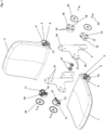
Fig. 1 shows an exploded view of a chair according to the first embodiment, with a foldable seat and a locked backrest; -
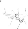
Fig. 2 shows a side view of the chair according to the first embodiment with the seat unfolded; -
Fig. 3 shows a side view of the chair according to the first embodiment with the seat folded; -
Fig. 4 shows an exploded view of a chair with a foldable seat and a locked backrest according to the second embodiment, where the frame arms are equipped with armrests; -
Fig. 5 shows a side view of the chair according to the second embodiment with the seat unfolded; -
Fig. 6 shows a side view of the chair according to the second embodiment with the seat folded; -
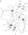
Fig. 7 shows an exploded view of a chair according to the third embodiment, with a foldable backrest and a locked seat; -
Fig. 8 shows a chair according to the third embodiment with the backrest folded out; -
Fig. 9 shows a chair according to the third embodiment with a folded backrest; -
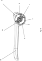
Fig. 10 shows a detailed view of the seat/backrest socket; -
Fig. 11 shows a detailed view of the hinge; -
Fig. 12 shows a detailed view of the lock. -
Fig. 13 shows a general view of the chair with a folded seat according to the fourth embodiment, where the seat is equipped with a lighting set from the bottom; -
Fig. 14 shows a block diagram of the lighting set; - The stadium chair in the first variant, with a tilting seat, consists of a
rigid assembly frame 3 and aseat 1 and abackrest 2, which have a rectangular shape, and each of them has athickening 4 on the same side in the part of the connection with the other part, which the thickening containssockets 5 for the hinge mechanism of theseat 1, where thesocket 5 has the shape of a round recess having ahole 6 in the center surrounded by asleeve 7 and aconcentric collar 8 with a diameter smaller than the diameter of thesocket 5 and thecollar 8 is connected to the perimeter of thesocket 5 by means of twoopposite walls 9 having an essentially trapezoidal shape, one of which has arecess 10. The circular-shaped hinge 11 has twopins 12 tangent to the edges, the shape of which corresponds to the shape of half of thefree spaces 13 formed between thewalls 9 and theflanges 8 of theseat 1. Moreover, the hinge has ahole 14 in the middle, extended towards thepins 12 with asleeve 15, on which sleeve 15 aspring 23 is placed, the arm of which is adapted to therecess 10 of thesocket 5, alock 16 in the shape of a circle having twopins 17 tangent to the edges, with a shape corresponding to the shape of thefree spaces 13 formed between the walls and flanges of thebackrest 2, and thelock 16 is located in thesocket 5 located in thethickening 4 of thebackrest 2, it has ahole 18 in the middle, which is extended towards itspins 17 with asleeve 19, and thepins 17 have a shape corresponding to the shape of thefree spaces 13 created between thewalls 9 andflanges 8 of thesockets 5 of thebackrest 2, where thelocks 16 haveprotrusions 20 on the side opposite thepins 17, and therigid mounting frame 3 has twoarms holes 21 corresponding to theprotrusions 20. Thehinges 11 are mounted in such a way that theirpins 12 are placed in thefree spaces 13 of the horizontally locatedseat 1 on both sides, and itsprotrusions 20 are placed in theholes 21 of one of thearms 3b of the rigid mounting frame, and theirsleeves 15 are placed in thesleeves 7 and pass through thehole 6 of thesocket 5 and are fastened with ascrew 22, and thelocks 16 are fastened in such a way that theirpins 17 are placed in thefree spaces 13 of the vertically locatedbackrest 2 on both sides, and itsprotrusions 20 are placed in theholes 21 of thesecond arm 3arigid assembly frame 3, and theirsleeves 19 are placed insleeves 7 and pass through thehole 6 of thesocket 5. Both thehinge 11 and thelock 16 are covered withmasking caps 24 on the outer side of theframe 3 and are fastened withscrews 22. - The stadium seat in the third embodiment has the same features as the stadium seat in the first embodiment, except that the
arm 3b of theframe 3 has at itsend extensions 25 placed at an obtuse angle in relation to thearms 3b, at the ends of whicharmrests 26 are attached. - The second variant of the stadium chair has a
foldable backrest 2 and anon-foldable seat 1. The chair has a similar structure and the structure of thehinge 11 and thelock 16 as in example 1, with the difference that thehinges 11 are mounted in such a way that theirpins 12 are placed infree spaces 13 of thesockets 5 of thebackrest 2, and thelocks 16 are mounted so that theirpins 17 are placed in thefree spaces 13sockets 5 of theseat 1. - Chairs of this type are usually installed in public facilities, such as sports halls, on drawer/sliding stands - where the chairs are placed on sliding drawers and in order to close them, it is necessary to fold the chair backrest.
- The stadium chair according to the fourth variant has all the features of the first variant, with the difference that additionally, the
seat 1 in the lower part is equipped with a lighting set including alighting unit 27 and aphotovoltaic cell 32, where theunit 27 is a housing in which abattery 28 connected to the system is located. 29, which in turn is connected to atwilight sensor 30 located outside the housing and anLED diode 31, as well as to aphotovoltaic cell 32, where thephotovoltaic cell 32 is placed on the underside of theseat 1. - The lighting kit, which is installed to the
seat 1 from the underside using known methods, in this case by gluing, works in such a way that when the exposure falls below a certain level, thetwilight sensor 30 located on the bottom of the housing sends a signal to thecontrol system 29 , which in turn turns on theLED 31, powering it from thebattery 28. Aphotovoltaic cell 32 is also connected to thecontrol system 29, from which thesystem 29 charges thebattery 28. - Each chair equipped with a lighting set provides lighting independently of the others, which reduces the risk of failure of the entire system and provides lighting in the event of, for example, sudden switching off of the lighting in a public facility or after dark.
-
- 1 - seat
- 2 - backrest
- 3 - mounting frame
- 3a/3b - mounting frame arms
- 4 - seat/backrest thickening
- 5 - mounting socket
- 6 - socket hole
- 7 - sleeve in the seat/backrest socket
- 8 - collar in the seat/backrest socket
- 9 - walls connecting the collar with the perimeter of the seat/backrest
- 10 - recess for mounting the spring
- 11 - hinge
- 12 - hinge pins
- 13 - free spaces between the walls connecting the seat/backrest sockets
- 14 - hinge hole
- 15 - hinge hole sleeve
- 16 - blockade
- 17 - lock pins
- 18 - lock hole
- 19 - lock hole sleeve
- 20 - hinge/lock lugs
- 21 -through holes in the mounting frame arms
- 22 - screw
- 23 - spring
- 24 - masking overlays
- 25 - frame arm extensions
- 26 - armrests
- 27 - lighting unit
- 28 - battery
- 29 - control system
- 30 - dusk sensor
- 31 - LED diode
- 32 - photovoltaic panel
Claims (9)
- A stadium chair with a hinge and locking mechanism, having a seat and a backrest and an assembly frame, characterized in that the seat (1) and the backrest (2) of essentially the same shape have thickenings (4) containing sockets (5) of hinge or lock, having a hole (6) in the center surrounded by a sleeve (7) and a concentric flange (8), in which sockets (5) hinges (11) or locks (16) in the shape of a circle are mounted, where the hinges (11) are equipped with pins (12) with a shape corresponding to the shape of preferably half of the free spaces (13) formed between the walls (9) and flanges (8) of the sockets (5) and having a through hole in the middle (14) extended towards the pins (12) with a sleeve (15), and the locks (16) are equipped with pins (17) with a shape corresponding to the shape of the free spaces (13) formed between the walls (9) and flanges (8) of the sockets (5) and have a through hole (18) in the middle and, in addition, the hinges (11) and the locks (16) have protrusions (20) on the side opposite the pins (12) and (17), while the mounting frame consists of two shaped two-arm brackets (3), whose horizontal arms (3b) include sockets seating (5) located in the thickenings (4) of the rear part (4) of the seat (1), and the vertical arms (3a) include mounting sockets (5) located in the thickening (4) of the lower part of the backrest (2).
- A stadium chair according to claim 1, characterized in that the hinges (11) are mounted such that their pins (12) are placed in the free spaces (13) of the sockets (5) of the seat (1), and the locks (16) are mounted such that their pins (17) are placed in the free spaces (13) of the sockets (5) of the backrest (2).
- A stadium chair according to claim 2, characterized in that the seat (1) is equipped with a lighting set including a lighting unit (27) and a photovoltaic cell (32).
- A stadium chair according to claim 3, characterized in that the unit (27) is a housing containing a battery (28) connected to a control system (29) which is connected to a dusk sensor (30) placed outside the housing and an LED diode (31) and a photovoltaic cell (32).
- A stadium seat according to claim 1, characterized in that the hinges (11) are mounted such that their pins (12) are placed in the free spaces (13) of the sockets (5) of the backrest (2), and the locks (16) are mounted such that their pins (17) are placed in the free spaces (13) of the seats (5) of the seat (1).
- A stadium seat according to claim 1, characterized in that a spring (23) is mounted in the sockets in which the hinges (11) are mounted, between the sleeve (7) and the flange (8), one of the ends of which is placed in the recess (10) of one of the walls (9), and the second one is based on one of the pins (12) of the hinge (11).
- A stadium seat according to claim 1, characterized in that the sleeves (15) of the hinge (11) or sleeves (19) of the lock (16) are attached to the sockets (5) with a screw (22).
- A stadium seat according to claim 1, characterized in that between the screw (22) and the arms (3a, 3b) of the brackets (3) pads (24) are placed with a diameter equal to the diameter of the hinge (11) or lock (16).
- A stadium chair according to claim 1, characterized in that the arms (3b) of the frame (3) have an extension (25) located at an obtuse angle in relation to the arms (3a), with armrests (26) mounted at the ends of which.
Applications Claiming Priority (1)
| Application Number | Priority Date | Filing Date | Title |
|---|---|---|---|
| PL443793A PL443793A1 (en) | 2023-02-15 | 2023-02-15 | Stadium seat |
Publications (3)
| Publication Number | Publication Date |
|---|---|
| EP4417089A1 true EP4417089A1 (en) | 2024-08-21 |
| EP4417089C0 EP4417089C0 (en) | 2025-07-16 |
| EP4417089B1 EP4417089B1 (en) | 2025-07-16 |
Family
ID=90675663
Family Applications (1)
| Application Number | Title | Priority Date | Filing Date |
|---|---|---|---|
| EP24157596.8A Active EP4417089B1 (en) | 2023-02-15 | 2024-02-14 | Stadium seat |
Country Status (2)
| Country | Link |
|---|---|
| EP (1) | EP4417089B1 (en) |
| PL (1) | PL443793A1 (en) |
Citations (7)
| Publication number | Priority date | Publication date | Assignee | Title |
|---|---|---|---|---|
| US1973178A (en) * | 1933-08-14 | 1934-09-11 | Interior Hardwood Company Ltd | Theater chair |
| DE29500672U1 (en) * | 1995-01-17 | 1995-05-18 | Held Großraumbestuhlungen Vertriebs GmbH, 82347 Bernried | Seat with a seat tube frame and a cup-shaped seat made of plastic |
| US20080217979A1 (en) | 2004-09-17 | 2008-09-11 | The Product People Pty Limited | Stadium Seat and a Method of Mounting a Stadium Seat |
| WO2011004220A1 (en) * | 2009-07-08 | 2011-01-13 | Teo A. Khing Design Consultants Sdn Bhd (Dubai Br.) | Foldable seat with a display or led on the underside portion |
| KR20120071791A (en) * | 2010-12-23 | 2012-07-03 | 내쇼날씨엔디 주식회사 | Chair with solar cell panels and stadium comprising of the same |
| US10092107B1 (en) * | 2015-05-14 | 2018-10-09 | Mark Johns Walker | Outdoor seating assembly having one or more photovoltaic panels |
| US20210321776A1 (en) | 2020-04-17 | 2021-10-21 | Blue Cube (Gb) Ltd | Stadium seat |
Family Cites Families (4)
| Publication number | Priority date | Publication date | Assignee | Title |
|---|---|---|---|---|
| CH483820A (en) * | 1968-09-12 | 1970-01-15 | Ticinfin Anstalt | Armchair especially for show halls |
| AUPQ297099A0 (en) * | 1999-09-21 | 1999-10-14 | Camatic Pty. Limited | Seating system |
| GB2468511A (en) * | 2009-03-12 | 2010-09-15 | Lea Mark Adams | Foldable stadium seating |
| PL65480Y1 (en) * | 2009-04-16 | 2011-06-30 | Hanplast Społka Z Ograniczoną Odpowiedzialnością | Folding stadium chair |
-
2023
- 2023-02-15 PL PL443793A patent/PL443793A1/en unknown
-
2024
- 2024-02-14 EP EP24157596.8A patent/EP4417089B1/en active Active
Patent Citations (7)
| Publication number | Priority date | Publication date | Assignee | Title |
|---|---|---|---|---|
| US1973178A (en) * | 1933-08-14 | 1934-09-11 | Interior Hardwood Company Ltd | Theater chair |
| DE29500672U1 (en) * | 1995-01-17 | 1995-05-18 | Held Großraumbestuhlungen Vertriebs GmbH, 82347 Bernried | Seat with a seat tube frame and a cup-shaped seat made of plastic |
| US20080217979A1 (en) | 2004-09-17 | 2008-09-11 | The Product People Pty Limited | Stadium Seat and a Method of Mounting a Stadium Seat |
| WO2011004220A1 (en) * | 2009-07-08 | 2011-01-13 | Teo A. Khing Design Consultants Sdn Bhd (Dubai Br.) | Foldable seat with a display or led on the underside portion |
| KR20120071791A (en) * | 2010-12-23 | 2012-07-03 | 내쇼날씨엔디 주식회사 | Chair with solar cell panels and stadium comprising of the same |
| US10092107B1 (en) * | 2015-05-14 | 2018-10-09 | Mark Johns Walker | Outdoor seating assembly having one or more photovoltaic panels |
| US20210321776A1 (en) | 2020-04-17 | 2021-10-21 | Blue Cube (Gb) Ltd | Stadium seat |
Also Published As
| Publication number | Publication date |
|---|---|
| EP4417089C0 (en) | 2025-07-16 |
| EP4417089B1 (en) | 2025-07-16 |
| PL443793A1 (en) | 2024-08-19 |
Similar Documents
| Publication | Publication Date | Title |
|---|---|---|
| US11980296B2 (en) | Frame assembly for folding type chair | |
| CA2099165C (en) | Auditorium seating system | |
| US20200305610A1 (en) | Housing and tilt mechanism for a chair and a chair, in particular an office chair | |
| EP0016200B1 (en) | Telescoping row system with beam-mounted automatically folding chairs | |
| EP0763338B1 (en) | A chair with a pivoting backrest | |
| US7367627B2 (en) | Armchair folding system | |
| US11672714B2 (en) | Electric wheelchair | |
| EP4417089B1 (en) | Stadium seat | |
| KR100978283B1 (en) | Height adjustable student desk | |
| US3727975A (en) | Folding stadium chair | |
| US3098677A (en) | Chair seat or the like hinge | |
| KR20200003988A (en) | The tilting chair | |
| KR200420098Y1 (en) | Table with chairs that fold up automatically | |
| US12396563B2 (en) | Flexing chair shell with flexible elements | |
| CN101247746B (en) | Folding chair | |
| US6161900A (en) | Adjustable and detachable armrest for chairs | |
| CN218791394U (en) | Office chair extends handrail structure | |
| CN110179270A (en) | Adjustable lie of one kind sits integrated chair | |
| US6254185B1 (en) | Wheelchair accessible stadium seating | |
| US2582600A (en) | Seat mounting for theater chairs or the like | |
| EP0608025A1 (en) | Seat and bed frames rotating in relation to the variable-setting back | |
| JPH0534944U (en) | Chair seat support device | |
| KR102112925B1 (en) | Transformable seating system for vehicle | |
| KR200294510Y1 (en) | Slim type folding stair in Elevator | |
| JPH07313284A (en) | Connecting chair |
Legal Events
| Date | Code | Title | Description |
|---|---|---|---|
| PUAI | Public reference made under article 153(3) epc to a published international application that has entered the european phase |
Free format text: ORIGINAL CODE: 0009012 |
|
| STAA | Information on the status of an ep patent application or granted ep patent |
Free format text: STATUS: THE APPLICATION HAS BEEN PUBLISHED |
|
| AK | Designated contracting states |
Kind code of ref document: A1 Designated state(s): AL AT BE BG CH CY CZ DE DK EE ES FI FR GB GR HR HU IE IS IT LI LT LU LV MC ME MK MT NL NO PL PT RO RS SE SI SK SM TR |
|
| STAA | Information on the status of an ep patent application or granted ep patent |
Free format text: STATUS: REQUEST FOR EXAMINATION WAS MADE |
|
| 17P | Request for examination filed |
Effective date: 20241219 |
|
| GRAP | Despatch of communication of intention to grant a patent |
Free format text: ORIGINAL CODE: EPIDOSNIGR1 |
|
| STAA | Information on the status of an ep patent application or granted ep patent |
Free format text: STATUS: GRANT OF PATENT IS INTENDED |
|
| INTG | Intention to grant announced |
Effective date: 20250226 |
|
| GRAS | Grant fee paid |
Free format text: ORIGINAL CODE: EPIDOSNIGR3 |
|
| GRAA | (expected) grant |
Free format text: ORIGINAL CODE: 0009210 |
|
| STAA | Information on the status of an ep patent application or granted ep patent |
Free format text: STATUS: THE PATENT HAS BEEN GRANTED |
|
| AK | Designated contracting states |
Kind code of ref document: B1 Designated state(s): AL AT BE BG CH CY CZ DE DK EE ES FI FR GB GR HR HU IE IS IT LI LT LU LV MC ME MK MT NL NO PL PT RO RS SE SI SK SM TR |
|
| REG | Reference to a national code |
Ref country code: GB Ref legal event code: FG4D |
|
| REG | Reference to a national code |
Ref country code: CH Ref legal event code: EP Ref country code: DE Ref legal event code: R096 Ref document number: 602024000298 Country of ref document: DE |
|
| REG | Reference to a national code |
Ref country code: IE Ref legal event code: FG4D |
|
| U01 | Request for unitary effect filed |
Effective date: 20250717 |
|
| U07 | Unitary effect registered |
Designated state(s): AT BE BG DE DK EE FI FR IT LT LU LV MT NL PT RO SE SI Effective date: 20250724 |
|
| PG25 | Lapsed in a contracting state [announced via postgrant information from national office to epo] |
Ref country code: IS Free format text: LAPSE BECAUSE OF FAILURE TO SUBMIT A TRANSLATION OF THE DESCRIPTION OR TO PAY THE FEE WITHIN THE PRESCRIBED TIME-LIMIT Effective date: 20251116 |
|
| PG25 | Lapsed in a contracting state [announced via postgrant information from national office to epo] |
Ref country code: NO Free format text: LAPSE BECAUSE OF FAILURE TO SUBMIT A TRANSLATION OF THE DESCRIPTION OR TO PAY THE FEE WITHIN THE PRESCRIBED TIME-LIMIT Effective date: 20251016 |
|
| PG25 | Lapsed in a contracting state [announced via postgrant information from national office to epo] |
Ref country code: HR Free format text: LAPSE BECAUSE OF FAILURE TO SUBMIT A TRANSLATION OF THE DESCRIPTION OR TO PAY THE FEE WITHIN THE PRESCRIBED TIME-LIMIT Effective date: 20250716 |
|
| PG25 | Lapsed in a contracting state [announced via postgrant information from national office to epo] |
Ref country code: GR Free format text: LAPSE BECAUSE OF FAILURE TO SUBMIT A TRANSLATION OF THE DESCRIPTION OR TO PAY THE FEE WITHIN THE PRESCRIBED TIME-LIMIT Effective date: 20251017 |
|
| PG25 | Lapsed in a contracting state [announced via postgrant information from national office to epo] |
Ref country code: PL Free format text: LAPSE BECAUSE OF FAILURE TO SUBMIT A TRANSLATION OF THE DESCRIPTION OR TO PAY THE FEE WITHIN THE PRESCRIBED TIME-LIMIT Effective date: 20250716 |
|
| PG25 | Lapsed in a contracting state [announced via postgrant information from national office to epo] |
Ref country code: RS Free format text: LAPSE BECAUSE OF FAILURE TO SUBMIT A TRANSLATION OF THE DESCRIPTION OR TO PAY THE FEE WITHIN THE PRESCRIBED TIME-LIMIT Effective date: 20251016 |
|
| PG25 | Lapsed in a contracting state [announced via postgrant information from national office to epo] |
Ref country code: ES Free format text: LAPSE BECAUSE OF FAILURE TO SUBMIT A TRANSLATION OF THE DESCRIPTION OR TO PAY THE FEE WITHIN THE PRESCRIBED TIME-LIMIT Effective date: 20250716 |
|
| U20 | Renewal fee for the european patent with unitary effect paid |
Year of fee payment: 3 Effective date: 20260203 |
|
| PG25 | Lapsed in a contracting state [announced via postgrant information from national office to epo] |
Ref country code: SM Free format text: LAPSE BECAUSE OF FAILURE TO SUBMIT A TRANSLATION OF THE DESCRIPTION OR TO PAY THE FEE WITHIN THE PRESCRIBED TIME-LIMIT Effective date: 20250716 |
|
| PG25 | Lapsed in a contracting state [announced via postgrant information from national office to epo] |
Ref country code: CZ Free format text: LAPSE BECAUSE OF FAILURE TO SUBMIT A TRANSLATION OF THE DESCRIPTION OR TO PAY THE FEE WITHIN THE PRESCRIBED TIME-LIMIT Effective date: 20250716 |
|
| PG25 | Lapsed in a contracting state [announced via postgrant information from national office to epo] |
Ref country code: SK Free format text: LAPSE BECAUSE OF FAILURE TO SUBMIT A TRANSLATION OF THE DESCRIPTION OR TO PAY THE FEE WITHIN THE PRESCRIBED TIME-LIMIT Effective date: 20250716 |
|
| PLBE | No opposition filed within time limit |
Free format text: ORIGINAL CODE: 0009261 |
|
| STAA | Information on the status of an ep patent application or granted ep patent |
Free format text: STATUS: NO OPPOSITION FILED WITHIN TIME LIMIT |
|
| REG | Reference to a national code |
Ref country code: CH Ref legal event code: L10 Free format text: ST27 STATUS EVENT CODE: U-0-0-L10-L00 (AS PROVIDED BY THE NATIONAL OFFICE) Effective date: 20260528 |
|
| 26N | No opposition filed |
Effective date: 20260417 |