EP4417070A1 - Aerosol generating device and control method and control device therefor, and readable storage medium - Google Patents
Aerosol generating device and control method and control device therefor, and readable storage medium Download PDFInfo
- Publication number
- EP4417070A1 EP4417070A1 EP22882537.8A EP22882537A EP4417070A1 EP 4417070 A1 EP4417070 A1 EP 4417070A1 EP 22882537 A EP22882537 A EP 22882537A EP 4417070 A1 EP4417070 A1 EP 4417070A1
- Authority
- EP
- European Patent Office
- Prior art keywords
- microwave
- feeding portion
- resonant cavity
- aerosol
- resonant
- Prior art date
- Legal status (The legal status is an assumption and is not a legal conclusion. Google has not performed a legal analysis and makes no representation as to the accuracy of the status listed.)
- Pending
Links
Images



Classifications
-
- A—HUMAN NECESSITIES
- A24—TOBACCO; CIGARS; CIGARETTES; SIMULATED SMOKING DEVICES; SMOKERS' REQUISITES
- A24F—SMOKERS' REQUISITES; MATCH BOXES; SIMULATED SMOKING DEVICES
- A24F40/00—Electrically operated smoking devices; Component parts thereof; Manufacture thereof; Maintenance or testing thereof; Charging means specially adapted therefor
- A24F40/40—Constructional details, e.g. connection of cartridges and battery parts
-
- A—HUMAN NECESSITIES
- A24—TOBACCO; CIGARS; CIGARETTES; SIMULATED SMOKING DEVICES; SMOKERS' REQUISITES
- A24F—SMOKERS' REQUISITES; MATCH BOXES; SIMULATED SMOKING DEVICES
- A24F40/00—Electrically operated smoking devices; Component parts thereof; Manufacture thereof; Maintenance or testing thereof; Charging means specially adapted therefor
- A24F40/40—Constructional details, e.g. connection of cartridges and battery parts
- A24F40/46—Shape or structure of electric heating means
-
- A—HUMAN NECESSITIES
- A24—TOBACCO; CIGARS; CIGARETTES; SIMULATED SMOKING DEVICES; SMOKERS' REQUISITES
- A24F—SMOKERS' REQUISITES; MATCH BOXES; SIMULATED SMOKING DEVICES
- A24F40/00—Electrically operated smoking devices; Component parts thereof; Manufacture thereof; Maintenance or testing thereof; Charging means specially adapted therefor
- A24F40/50—Control or monitoring
-
- A—HUMAN NECESSITIES
- A24—TOBACCO; CIGARS; CIGARETTES; SIMULATED SMOKING DEVICES; SMOKERS' REQUISITES
- A24F—SMOKERS' REQUISITES; MATCH BOXES; SIMULATED SMOKING DEVICES
- A24F40/00—Electrically operated smoking devices; Component parts thereof; Manufacture thereof; Maintenance or testing thereof; Charging means specially adapted therefor
- A24F40/50—Control or monitoring
- A24F40/57—Temperature control
-
- H—ELECTRICITY
- H05—ELECTRIC TECHNIQUES NOT OTHERWISE PROVIDED FOR
- H05B—ELECTRIC HEATING; ELECTRIC LIGHT SOURCES NOT OTHERWISE PROVIDED FOR; CIRCUIT ARRANGEMENTS FOR ELECTRIC LIGHT SOURCES, IN GENERAL
- H05B6/00—Heating by electric, magnetic or electromagnetic fields
- H05B6/64—Heating using microwaves
- H05B6/6402—Aspects relating to the microwave cavity
-
- H—ELECTRICITY
- H05—ELECTRIC TECHNIQUES NOT OTHERWISE PROVIDED FOR
- H05B—ELECTRIC HEATING; ELECTRIC LIGHT SOURCES NOT OTHERWISE PROVIDED FOR; CIRCUIT ARRANGEMENTS FOR ELECTRIC LIGHT SOURCES, IN GENERAL
- H05B6/00—Heating by electric, magnetic or electromagnetic fields
- H05B6/64—Heating using microwaves
- H05B6/80—Apparatus for specific applications
-
- A—HUMAN NECESSITIES
- A24—TOBACCO; CIGARS; CIGARETTES; SIMULATED SMOKING DEVICES; SMOKERS' REQUISITES
- A24F—SMOKERS' REQUISITES; MATCH BOXES; SIMULATED SMOKING DEVICES
- A24F40/00—Electrically operated smoking devices; Component parts thereof; Manufacture thereof; Maintenance or testing thereof; Charging means specially adapted therefor
- A24F40/20—Devices using solid inhalable precursors
Definitions
- the present application relates to the field of aerosol technology, specifically, to an aerosol generating device, a control method and a control device therefor, and a readable storage medium.
- a microwave is fed from a resonant cavity by the aerosol generating device, but the microwave generally acts on only one position of the object to be atomized (such as the aerosol-forming substrate), thus causing technical problems that the atomized object is heated unevenly, and that the atomization effect is poor.
- the present application aims to solve at least one of the technical problems existing in the prior art.
- the application provides an aerosol generating device.
- the application provides a control method for aerosol generating device.
- the application provides a control device for aerosol generating device.
- the application provides a readable storage medium.
- the present application provides an aerosol generating device, including: a housing, the housing having a resonant cavity; a first resonant column arranged in the resonant cavity and disposed at the top of the resonant cavity, the first resonant column being hollow to allow an aerosol-forming substrate to be arranged therein; a second resonant column arranged in the resonant cavity and disposed at the bottom of the resonant cavity; and a microwave assembly arranged on the housing, wherein: the microwave assembly includes a first microwave-feeding portion and a second microwave-feeding portion; the first microwave-feeding portion is configured to feed microwave to the top of the resonant cavity; and the second microwave-feeding portion is configured to feed microwave to the bottom of the resonant cavity.
- the aerosol generating device proposed in the present application includes the housing, the first resonant column, the second resonant column, and the microwave assembly.
- the resonant cavity is formed inside the housing, and an inside of the resonant cavity is conductive.
- the first resonant column and the second resonant column are both arranged in the resonant cavity, and the first resonant column and the second resonant column are configured to transmit microwave and adjust a resonant frequency, and the first resonant column and the second resonant column each are in conductive contact with an inner wall of the resonant cavity.
- Outer walls of the first resonant column and second resonant column are conductive.
- the first resonant column is disposed at the top of the resonant cavity, and the second resonant column is disposed at the bottom of the resonant cavity.
- the first resonant column is hollow, such that the aerosol-forming substrate may be installed inside the first resonant column, and it is ensured that at least part of the aerosol-forming substrate is located inside the resonant cavity 104.
- the second resonant column may be solid or hollow.
- the microwave assembly includes the first microwave-feeding portion and the second microwave-feeding portion.
- the first microwave-feeding portion is arranged at the top of the housing and engages with the first resonant column
- the second microwave-feeding portion is arranged at the top of the housing and engages with the second resonant column.
- the first microwave-feeding portion feeds the microwave generated by the microwave assembly to the top of the resonant cavity
- the second microwave-feeding portion feeds the microwave generated by the microwave assembly to the bottom of the resonant cavity.
- the microwave fed into the resonant cavity by the first microwave-feeding portion may heat the first portion of the aerosol-forming substrate
- the microwave fed into the resonant cavity by the second microwave-feeding portion may heat the second portion of the aerosol-forming substrate.
- the first portion is higher than the second portion. That is, during usage, the aerosol generating device proposed in the present application may heat at least two positions of the aerosol-forming substrate, and may heat the top and bottom of the aerosol-forming substrate at the same time, thus greatly improving the heating efficiency for the aerosol-forming substrate, accelerating the generation of the aerosol, and improving the working efficiency of the aerosol generating device.
- first resonant column and the second resonant column may serve as conductors, and the first resonant column and the second resonant column may be made of metallic materials.
- first resonant column and the second resonant column are made of copper, aluminum, iron, etc., or an alloy thereof.
- the first resonant column and the second resonant column are configured to transmit microwave and improve the microwave transmission rate. The microwave is not prone to attenuation when it is transmitted inside the resonant cavity.
- the first resonant column and the second resonant column may guide transmission of the microwave to the aerosol-forming substrate, so that the microwave may act on the aerosol-forming substrate.
- the aerosol-forming substrate absorbs the microwave, and polar molecules in the aerosol-forming substrate vibrate rapidly to generate thermal energy, thereby heating the aerosol-forming substrate.
- part of the aerosol-forming substrate may also extend into the resonant cavity, thus preventing the microwave from being transmitted to the outside of the housing to cause a leakage, and avoiding harm to a user.
- the first resonant column comprises a first opening and a second opening, the second opening is connected with the resonant cavity, and there is a first space between the second opening and the top of the second resonant column; at least part of the aerosol-forming substrate is capable of extending into the first resonant column through the first opening and extending into the resonant cavity through the second opening.
- the first resonant column comprises the first opening and the second opening.
- the first opening at the top of the first resonant column allows the user to insert the aerosol-forming substrate into the first resonant column.
- the second opening at the bottom of the first resonant column is connected with the resonant cavity. There is the first space between the second opening and the top of the second resonant column at the bottom of resonant cavity.
- At least part of the aerosol-forming substrate located inside the first resonant column extends into the resonant cavity through the first opening, such that, during the usage of the aerosol generating device, the microwave provided by the microwave assembly may be ensured to act on the aerosol-forming substrate, thus causing the polar molecules in the aerosol-forming substrate to vibrate rapidly to generate heat energy to heat the aerosol-forming substrate.
- the microwave assembly further includes the microwave emission source.
- the microwave emission source is connected to the first microwave-feeding portion and the second microwave-feeding portion, respectively, such that the microwave generated by the microwave emission source is fed into the resonant cavity through the first microwave-feeding portion and second microwave-feeding portion, respectively.
- the microwave emission source includes: a first microwave emission source connected to the first microwave-feeding portion; and a second microwave emission source connected to the second microwave-feeding portion.
- the microwave emission source includes the first microwave emission source and the second microwave emission source.
- the first microwave emission source is connected to the first microwave-feeding portion, and the microwave generated by the first microwave emission source may be fed to the top of the resonant cavity through the first microwave-feeding portion.
- the second microwave emission source is connected to the second microwave-feeding portion, and the microwave generated by the second microwave emission source may be fed to the bottom of the resonant cavity through the second microwave-feeding portion.
- microwaves are generated by the first microwave emission source and the second microwave emission source that are independent of each other, such that the aerosol-forming substrate may be heated according to actual needs of the user.
- the top of the aerosol-forming substrate may be heated through the first microwave emission source and the first microwave-feeding portion.
- the bottom of the aerosol-forming substrate may also be heated through the second microwave emission source and the second microwave-feeding portion.
- the top and bottom of the aerosol-forming substrate may also be heated through the first microwave emission source and the first microwave-feeding portion, and through the second microwave emission source and the second microwave-feeding portion.
- the first microwave-feeding portion is arranged on a side wall of the resonant cavity; and/or the second microwave-feeding portion is arranged on the side wall of the resonant cavity.
- the first microwave-feeding portion is arranged on the side wall of the resonant cavity, such that the microwave generated by the microwave assembly is fed from the side of the resonant cavity to the interior of the resonant cavity.
- the second microwave-feeding portion is arranged on the side wall of the resonant cavity, such that the microwave generated by the microwave assembly is fed into the interior of the resonant cavity from the side of the resonant cavity.
- the first microwave-feeding portion and the second microwave-feeding portion are arranged on the side wall of the resonant cavity, thereby reasonably arranging the positions of the first microwave-feeding portion and the second microwave-feeding portion, and reducing the length of the whole aerosol generating device.
- a feeding end of the first microwave-feeding portion is disposed towards the first resonant column; and/or a feeding end of the second microwave-feeding portion is disposed towards the second resonant column.
- a feeding end of the first microwave-feeding portion is disposed towards the top wall of the resonant cavity; and/or a feeding end of the second microwave-feeding portion is disposed towards the bottom wall of the resonant cavity.
- the first microwave-feeding portion is L-shaped, the feeding end of the first microwave-feeding portion is disposed towards the top wall of the resonant cavity, and the feeding end of the first microwave-feeding portion is directly in conduction with the top wall of the resonant cavity, such that part of the microwaves generated by the microwave assembly may be directly fed to the top wall of the resonant cavity through the first microwave-feeding portion.
- the second microwave-feeding portion is L-shaped, the feeding end of the second microwave-feeding portion is directly in conduction with the bottom wall of the resonant cavity, and the feeding end of the second microwave-feeding portion is disposed towards the bottom wall of the resonant cavity, such that part of the microwaves generated by the microwave assembly may be directly fed to the bottom wall of the resonant cavity through the second microwave-feeding portion.
- the top wall of the resonant cavity comprises a first recess, and the feeding end of the first microwave-feeding portion is arranged in the first recess; and/or the bottom wall of the resonant cavity comprises a second recess, and the feeding end of the second microwave-feeding portion is arranged in the second recess.
- the top wall of the resonant cavity comprises the first recess, and the feeding end of the first microwave-feeding portion is arranged in the first recess, such that the first recess can protect the feeding end of the first microwave-feeding portion, prevent the feeding end of the first microwave-feeding portion from contacting other components, and improve the structural stability of the microwave atomizing and heating device.
- the bottom wall of the resonant cavity comprises the second recess, and the feeding end of the second microwave-feeding portion is arranged in the second recess, such that the second recess can protect the feeding end of the second microwave-feeding portion, prevent the feeding end of the second microwave-feeding portion from contacting other components, and improve the structural stability of the microwave atomizing and heating device.
- a central axis of the first resonant column and a central axis of the resonant cavity coincide; and a central axis of the second resonant column and the central axis of the resonant cavity coincide.
- the first resonant column and the resonant cavity both have regular shapes.
- the first resonant column and the resonant cavity each are in the shape of a cylinder.
- the central axis of the first resonant column and the central axis of the resonant cavity coincide. That is, the axis of the first resonant column coincides with the axis of the resonant cavity.
- the second resonant column and the resonant cavity both have regular shapes.
- the second resonant column and the resonant cavity each are in the shape of the cylinder.
- the central axis of the second resonant column and the central axis of the resonant cavity coincide. That is, the axis of the second resonant column coincides with the axis of the resonant cavity.
- the first resonant column is connected to the top wall of the resonant cavity; and/or the second resonant column is connected to the bottom wall of the resonant cavity.
- the first resonant column is connected to the top wall of the resonant cavity, such that, on one hand, the first resonant column is ensured to be stably connected, and on the other hand, the first resonant column may directly convey microwaves through the top of the resonant cavity, thereby improving the effect of conveying microwaves.
- the second resonant column is connected to the bottom wall of the resonant cavity, such that, on one hand, the second resonant column is ensured to be stably connected, and on the other hand, the second resonant column may directly convey microwaves through the bottom wall of the resonant cavity, thereby improving the effect of conveying microwaves.
- the resonant cavity is a cylindrical cavity.
- the resonant cavity is the cylindrical cavity.
- the first resonant column and the second resonant column both have cylindrical structures.
- the central axis of the first resonant column and the central axis of the resonant cavity coincide, and the central axis of the second resonant column and the central axis of the resonant cavity coincide.
- the housing is a metal housing.
- the housing is a metal housing.
- the housing is made of copper, aluminum, iron, etc., or an alloy thereof.
- the second aspect of the present application provides a control method for an aerosol generating device, which can be used in any one of the aerosol generating devices described above.
- the control method includes: controlling at least one of the first microwave-feeding portion and the second microwave-feeding portion to feed microwave into the resonant cavity in response to an atomization instruction.
- the control method for aerosol generating device proposed in the present application may be used in any one of the aerosol generating devices described above.
- at least one of the first microwave-feeding portion and the second microwave-feeding portion is controlled to feed microwave into the resonant cavity.
- the microwave fed into the resonant cavity through the first microwave-feeding portion may heat the first portion of the aerosol-forming substrate, and the microwave fed into the resonant cavity through the second microwave-feeding portion may heat the second portion of the aerosol-forming substrate.
- the first portion is higher than the second portion.
- the control method for aerosol generating device proposed in the present application may heat the aerosol-forming substrate according to an actual selection of the user. Specifically, the top of the aerosol-forming substrate may be heated through the first microwave-feeding portion. Alternatively, the bottom of the aerosol-forming substrate may be heated through the second microwave-feeding portion. Alternatively, the top and bottom of the aerosol-forming substrate may be heated through the first microwave-feeding portion, the second microwave emission source and the second microwave-feeding portion.
- At least two positions of the aerosol generating device of the present application can be heated, and the top and bottom of the aerosol-forming substrate may be heated simultaneously, thereby greatly improving the heating efficiency for the aerosol-forming substrate, accelerating the generation of the aerosol, and improving the working efficiency of the aerosol generating device.
- control method specifically includes: controlling the first microwave-feeding portion and the second microwave-feeding portion to feed microwave into the resonant cavity simultaneously in response to the atomization instruction.
- the first microwave-feeding portion and the second microwave-feeding portion are controlled to feed microwaves into the resonant cavity simultaneously, such that the microwave fed into the resonant cavity through the first microwave-feeding portion may heat the first portion of the aerosol-forming substrate, and at the same time, the microwave fed into the resonant cavity through the second microwave-feeding portion may heat the second portion of the aerosol-forming substrate.
- the top and bottom of the aerosol-forming substrate may be heated simultaneously, thereby greatly improving the heating efficiency for the aerosol-forming substrate, accelerating the generation of the aerosol, and improving the working efficiency of the aerosol generating device.
- control method for aerosol generating device specifically includes: controlling the first microwave-feeding portion to feed microwave into the resonant cavity to heat a first portion of the aerosol-forming substrate to a first temperature in response to the atomization instruction; and controlling the second microwave-feeding portion to feed microwave into the resonant cavity after the first microwave-feeding portion works for a preset time period to heat a second portion of the aerosol-forming substrate to a second temperature.
- the second temperature is higher than or equal to the first temperature.
- the first microwave-feeding portion in response to the atomization instruction, is controlled to feed microwave into the resonant cavity firstly, and the first portion of the aerosol-forming substrate is heated to the first temperature. Then, after the first microwave-feeding portion works for the preset time period, the second microwave-feeding portion is controlled to feed microwave into the resonant cavity, and the second portion of the aerosol-forming substrate is heated to a second temperature. Moreover, the second temperature is higher than the first temperature.
- the microwave is fed into the top of the resonant cavity through the first microwave-feeding portion firstly, but the microwave is not fed into the bottom of the resonant cavity, and at this time, the upper half portion of the aerosol-forming substrate is heated, and it is ensured that the temperature of the upper half portion of the aerosol-forming substrate is the first temperature. Then, after the upper half portion of the aerosol-forming substrate is heated to a certain extent, the microwave is fed into the bottom of the resonant cavity through the microwave-feeding portion, and at this time, the lower half portion of the aerosol-forming substrate is heated, and it is ensured that the temperature of the lower half portion of the aerosol-forming substrate is the second temperature.
- the first microwave-feeding portion is controlled to feed microwave into the resonant cavity to heat the first portion of the aerosol-forming substrate to a third temperature, the third temperature is less than or equal to the first temperature.
- the microwave may be fed into the top of the resonant cavity through the microwave-feeding portion, and it is ensured that the first portion of the aerosol-forming substrate is heated to the third temperature, where the third temperature is less than or equal to the first temperature.
- the first microwave-feeding portion is controlled to stop working.
- the first microwave-feeding portion may be controlled to stop working. At this time, the microwave is fed into the resonant cavity only through the second microwave-feeding portion.
- the third aspect of the present application provides a control device for aerosol generating device, which can be used in any one of the aerosol generating devices described above.
- the control device includes a control unit configured to control at least one of the first microwave-feeding portion and the second microwave-feeding portion to feed microwave into the resonant cavity in response to an atomization instruction.
- control device for aerosol generating device proposed in the present application may be used in any one of the aerosol generating devices above.
- the control device for aerosol generating device includes the control unit.
- the control unit controls at least one of the first microwave-feeding portion and the second microwave-feeding portion to feed microwaves into the resonant cavity.
- the microwave fed into the resonant cavity through the first microwave-feeding portion may heat the first portion of the aerosol-forming substrate, and the microwave fed into the resonant cavity through the second microwave-feeding portion may heat the second portion of the aerosol-forming substrate.
- the first portion is higher than the second portion.
- the aerosol-forming substrate may be heated according to an actual selection of the user. Specifically, the top of the aerosol-forming substrate may be heated via the first microwave-feeding portion. Alternatively, the bottom of the aerosol-forming substrate may be heated via the second microwave-feeding portion. Alternatively, the top and bottom of the aerosol-forming substrate may be heated via the first microwave-feeding portion, the second microwave emission source, and the second microwave-feeding portion.
- At least two positions of the aerosol generating device of the present application may be heated, and the top and bottom of the aerosol-forming substrate may be heated simultaneously, thereby greatly improving the heating efficiency for the aerosol-forming substrate, accelerating the generation of the aerosol, and improving the working efficiency of the aerosol generating device.
- the fourth aspect of the present application provides a readable storage medium, on which a program is stored.
- the program is executed by a processor, steps of any one of the control methods for aerosol generating device are implemented.
- the readable storage medium proposed in the fourth aspect of the present application, when the program stored thereon is executed, the steps of any one of the control methods for aerosol generating device are implemented. Therefore, the readable storage medium can achieve all the same beneficial effects as the control method for aerosol generating device, which will not be described in detail herein.
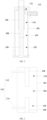
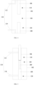
- corresponding relationships between reference signs in FIGS. 1 to 9 and names of components are: 102 housing, 104 resonant cavity, 106 first resonant column, 108 second resonant column, 110 microwave assembly, 112 first microwave-feeding portion, 114 second microwave-feeding portion, 116 first recess, 118 second space, 120 third space, 200 aerosol-forming substrate, 202 first portion, 204 second portion, 300 aerosol, 400 installing structure.
- FIGS. 1 to 12 An aerosol generating device, a control method and a control device for the aerosol generating device, and readable storage medium of the present application are described hereinafter with reference to FIGS. 1 to 12 .
- a second microwave-feeding portion 114 is not shown.
- a line segment L1 shows a relationship between a heating temperature of the first portion 202 and a heating time.
- a line segment L2 shows a relationship between a heating temperature of the second portion 204 and a heating time.
- a first embodiment of the present application proposes an aerosol generating device, including a housing 102, a first resonant column 106, a second resonant column 108, and a microwave assembly 110.
- a resonant cavity 104 is formed inside the housing 102, and an inside of the resonant cavity 104 is conductive.
- the first resonant column 106 and the second resonant column 108 are both arranged in the resonant cavity 104, and the first resonant column 106 and the second resonant column 108 are configured to transmit microwave and adjust a resonant frequency, and the first resonant column 106 and the second resonant column 108 each are in conductive contact with an inner wall of the resonant cavity 104.
- Outer walls of the first resonant column 106 and second resonant column 108 are conductive.
- the first resonant column 106 is disposed at the top of the resonant cavity 104
- the second resonant column 108 is disposed at the bottom of the resonant cavity 104.
- the first resonant column 106 is hollow, such that the aerosol-forming substrate 200 may be installed inside the first resonant column 106, and it is ensured that at least part of the aerosol-forming substrate 200 is located inside the resonant cavity 104.
- the second resonant column 108 may be solid or hollow.
- the microwave fed into the resonant cavity 104 by the first microwave-feeding portion 112 may heat a first portion 202 of the aerosol-forming substrate 200
- the microwave fed into the resonant cavity 104 by the second microwave-feeding portion 114 may heat a second portion 204 of the aerosol-forming substrate 200.
- the first portion 202 is higher than the second portion 204.
- the aerosol generating device proposed in the present application may heat at least two positions of the aerosol-forming substrate 200, and may heat the top and bottom of the aerosol-forming substrate 200 at the same time, thus greatly improving the heating efficiency for the aerosol-forming substrate 200, accelerating the generation of the aerosol 300, and improving the working efficiency of the aerosol generating device.
- first resonant column 106 and the second resonant column 108 may serve as conductors, and the first resonant column 106 and the second resonant column 108 may be made of metallic materials.
- the first resonant column 106 and the second resonant column 108 are made of copper, aluminum, iron, etc., or an alloy thereof.
- the first resonant column 106 and the second resonant column 108 are configured to transmit microwave and improve the microwave transmission rate. The microwave is not prone to attenuation when it is transmitted inside the resonant cavity 104.
- the first resonant column 106 and the second resonant column 108 may guide transmission of the microwave to the aerosol-forming substrate 200, so that the microwave may act on the aerosol-forming substrate 200.
- the aerosol-forming substrate 200 absorbs the microwave, and polar molecules in the aerosol-forming substrate 200 vibrate rapidly to generate thermal energy, thereby heating the aerosol-forming substrate 200.
- part of the aerosol-forming substrate 200 may also extend into the resonant cavity 104, thus preventing the microwave from being transmitted to the outside of the housing 102 to cause a leakage, and avoiding harm to a user.
- the first resonant column 106 comprises a first opening and a second opening.
- the first opening at the top of the first resonant column 106 allows the user to insert the aerosol-forming substrate 200 into the first resonant column 106.
- the second opening at the bottom of the first resonant column 106 is connected with the resonant cavity 104.
- At least part of the aerosol-forming substrate 200 located inside the first resonant column 106 extends into the resonant cavity 104 through the first opening, such that, during the usage of the aerosol generating device, the microwave provided by the microwave assembly 110 may be ensured to act on the aerosol-forming substrate 200, thus causing the polar molecules in the aerosol-forming substrate 200 to vibrate rapidly to generate heat energy to heat the aerosol-forming substrate 200.
- the aerosol-forming substrate 200 includes the first portion 202 of the top and the second portion 204 of the bottom.
- the aerosol-forming substrate 200 needs to be installed inside the installing structure 400. That is, in the working process of the aerosol generating device, the user inserts the installing structure 400 installed with the aerosol-forming substrate 200 into the first resonant column 106, so that the aerosol-forming substrate 200 is located inside the resonant cavity 104 and located between the first resonant column 106 and the second resonant column 108, such that the microwave conveyed through the first resonant column 106 directly acts on the first portion 202 at the top of the aerosol-forming substrate 200, and the microwave conveyed through the second resonant column 108 directly acts on the second portion 204 of the top of the aerosol-forming substrate 200.
- a third embodiment of the application further proposes an aerosol generating device based on the first embodiment.
- the microwave assembly 110 further includes a microwave emission source (not shown in the figures).
- the microwave emission source is connected to the first microwave-feeding portion 112 and the second microwave-feeding portion 114, respectively, such that the microwave generated by the microwave emission source is fed into the resonant cavity 104 through the first microwave-feeding portion 112 and second microwave-feeding portion 114, respectively.
- the microwave emission source includes a first microwave emission source (not shown in the figures) and a second microwave emission source (not shown in the figures).
- the first microwave emission source is connected to the first microwave-feeding portion 112, and the microwave generated by the first microwave emission source may be fed to the top of the resonant cavity 104 through the first microwave-feeding portion 112.
- the second microwave emission source is connected to the second microwave-feeding portion 114, and the microwave generated by the second microwave emission source may be fed to the bottom of the resonant cavity 104 through the second microwave-feeding portion 114.
- microwaves are generated by the first microwave emission source and the second microwave emission source that are independent of each other, such that the aerosol-forming substrate 200 may be heated according to actual needs of the user.
- the top of the aerosol-forming substrate 200 may be heated through the first microwave emission source and the first microwave-feeding portion 112, so that the aerosol 300 is firstly generated from the first portion 202.
- the bottom of the aerosol-forming substrate 200 may also be heated through the second microwave emission source and the second microwave-feeding portion 114, so that the aerosol 300 is firstly generated in the second portion 204.
- FIG. 7 the top of the aerosol-forming substrate 200 may be heated through the first microwave emission source and the first microwave-feeding portion 112, so that the aerosol 300 is firstly generated from the first portion 202.
- the bottom of the aerosol-forming substrate 200 may also be heated through the second microwave emission source and the second microwave-feeding portion 114, so that the aerosol 300 is firstly generated in the second portion 204.
- the top and bottom of the aerosol-forming substrate 200 may also be heated through the first microwave emission source and the first microwave-feeding portion 112, and through the second microwave emission source and the second microwave-feeding portion 114, so that the aerosol 300 is generated at the same time from the first portion 202 and from the second portion 204.
- a fourth embodiment of the application further proposes an aerosol generating device based on the first embodiment.
- the first microwave-feeding portion 112 is arranged on the side wall of the resonant cavity 104, such that the microwave generated by the microwave assembly 110 is fed from the side of the resonant cavity 104 to the interior of the resonant cavity 104.
- the second microwave-feeding portion 114 is arranged on the side wall of the resonant cavity 104, such that the microwave generated by the microwave assembly 110 is fed into the interior of the resonant cavity 104 from the side of the resonant cavity 104.
- first microwave-feeding portion 112 and the second microwave-feeding portion 114 are arranged on the side wall of the resonant cavity 104, thereby reasonably arranging the positions of the first microwave-feeding portion 112 and the second microwave-feeding portion 114, and reducing the length of the whole aerosol generating device.
- a fifth embodiment of the present application further proposes an aerosol generating device based on the first embodiment.
- a feeding end of the first microwave-feeding portion 112 is disposed towards the first resonant column 106, and the feeding end of the first microwave-feeding portion 112 is directly in conduction with the first resonant column 106, such that part of the microwaves generated by the microwave assembly 110 may be directly fed to the first resonant column 106 through the first microwave-feeding portion 112.
- a feeding end of the second microwave-feeding portion 114 is disposed towards the second resonant column 108, and the feeding end of the second microwave-feeding portion 114 is directly in conduction with the second resonant column 108, such that part of the microwaves generated by the microwave assembly 110 may be directly fed to the second resonant column 108 through the second microwave-feeding portion 114.
- the microwaves fed through the first microwave-feeding portion 112 and second microwave-feeding portion 114 may directly act on the first resonant column 106 and on the second resonant column 108, such that, on one hand, lengths of the first microwave-feeding portion 112 and second microwave-feeding portion 114 may be reduced, and on the other hand, the microwaves may be quickly fed to the first resonant column 106 and second resonant column 108, thereby avoiding a microwave loss.
- a sixth embodiment of the present application further proposes an aerosol generating device based on the first embodiment.
- the first microwave-feeding portion 112 is L-shaped, the feeding end of the first microwave-feeding portion 112 is disposed towards the top wall of the resonant cavity 104, and the feeding end of the first microwave-feeding portion 112 is directly in conduction with the top wall of the resonant cavity 104, such that part of the microwaves generated by the microwave assembly 110 may be directly fed to the top wall of the resonant cavity 104 through the first microwave-feeding portion 112.
- the second microwave-feeding portion 114 is L-shaped, the feeding end of the second microwave-feeding portion 114 is directly in conduction with the bottom wall of the resonant cavity 104, and the feeding end of the second microwave-feeding portion 114 is disposed towards the bottom wall of the resonant cavity 104, such that part of the microwaves generated by the microwave assembly 110 may be directly fed to the bottom wall of the resonant cavity 104 through the second microwave-feeding portion 114.
- the top wall of the resonant cavity 104 comprises a first recess 116, and the feeding end of the first microwave-feeding portion 112 is arranged in the first recess 116, such that the first recess 116 can protect the feeding end of the first microwave-feeding portion 112, prevent the feeding end of the first microwave-feeding portion 112 from contacting other components, and improve the structural stability of the microwave atomizing and heating device.
- the bottom wall of the resonant cavity 104 comprises a second recess (not shown in the figures), and the feeding end of the second microwave-feeding portion 114 is arranged in the second recess, such that the second recess can protect the feeding end of the second microwave-feeding portion 114, prevent the feeding end of the second microwave-feeding portion 114 from contacting other components, and improve the structural stability of the microwave atomizing and heating device.
- the first resonant column 106 and the resonant cavity 104 both have regular shapes.
- the first resonant column 106 and the resonant cavity 104 each are in a shape of a cylinder.
- a central axis of the first resonant column 106 and a central axis of the resonant cavity 104 coincide. That is, the axis of the first resonant column 106 coincides with the axis of the resonant cavity 104.
- the center lines of the first resonant column 106 and resonant cavity 104 are arranged to coincide, centers of the first resonant column 106 and aerosol-forming substrate 200 coincide, such that more microwaves conducted by the first resonant column 106 can act on the aerosol-forming substrate 200.
- the aerosol-forming substrate 200 can be heated within a relatively short time, which is beneficial to realizing instant heating.
- the second resonant column 108 and the resonant cavity 104 both have regular shapes.
- the second resonant column 108 and the resonant cavity 104 each are in a shape of a cylinder.
- a central axis of the second resonant column 108 and the central axis of the resonant cavity 104 coincide. That is, the axis of the second resonant column 108 coincides with the axis of the resonant cavity 104.
- the center lines of the second resonant column 108 and resonant cavity 104 By arranging the center lines of the second resonant column 108 and resonant cavity 104 to coincide, the centers of the second resonant column 108 and the aerosol-forming substrate 200 coincide, such that more microwaves conducted by the second resonant column 108 can act on the aerosol-forming substrate 200.
- the aerosol-forming substrate 200 can be heated within a relatively short time, which is beneficial to realizing instant heating.
- the second resonant column 108 is connected to the bottom wall of the resonant cavity 104, such that, on one hand, the second resonant column 108 is ensured to be stably connected, and on the other hand, the second resonant column 108 may directly convey microwaves through the bottom wall of the resonant cavity 104, thereby improving the effect of conveying microwaves.
- the resonant cavity 104 is a cylindrical cavity.
- the first resonant column 106 and the second resonant column 108 both have cylindrical structures.
- the central axis of the first resonant column 106 and the central axis of the resonant cavity 104 coincide, and the central axis of the second resonant column 108 and the central axis of the resonant cavity 104 coincide.
- the microwave evenly heats the whole aerosol-forming substrate 200, thereby improving the heating effect for the aerosol-forming substrate 200.
- the housing 102 is a metal housing.
- the housing 102 is made of copper, aluminum, iron, etc., or an alloy thereof.
- a seventh embodiment of the present application further proposes a control method for aerosol generating device, which may be used in any one of the aerosol generating devices described above. As shown in FIG. 11 , the control method for the aerosol generating device includes following steps.
- Step 1102 in response to an atomization instruction, at least one of the first microwave-feeding portion and the second microwave-feeding portion is controlled to feed microwave into the resonant cavity.
- the control method for aerosol generating device proposed in the present application may be used in any one of the aerosol generating devices described above.
- at least one of the first microwave-feeding portion and the second microwave-feeding portion is controlled to feed microwave into the resonant cavity.
- the microwave fed into the resonant cavity through the first microwave-feeding portion may heat the first portion of the aerosol-forming substrate, and the microwave fed into the resonant cavity through the second microwave-feeding portion may heat the second portion of the aerosol-forming substrate.
- the first portion is higher than the second portion.
- the control method for aerosol generating device proposed in the present application may heat the aerosol-forming substrate according to an actual selection of the user. Specifically, the top of the aerosol-forming substrate may be heated through the first microwave-feeding portion. Alternatively, the bottom of the aerosol-forming substrate may be heated through the second microwave-feeding portion. Alternatively, the top and bottom of the aerosol-forming substrate may be heated through the first microwave-feeding portion, the second microwave emission source and the second microwave-feeding portion.
- At least two positions of the aerosol generating device of the present application can be heated, and the top and bottom of the aerosol-forming substrate may be heated simultaneously, thereby greatly improving the heating efficiency for the aerosol-forming substrate, accelerating the generation of the aerosol, and improving the working efficiency of the aerosol generating device.
- An eighth embodiment of the present application further proposes a control method for aerosol generating device based on the seventh embodiment.
- the first microwave-feeding portion and the second microwave-feeding portion are controlled to feed microwaves into the resonant cavity simultaneously, such that the microwave fed into the resonant cavity through the first microwave-feeding portion may heat the first portion of the aerosol-forming substrate, and at the same time, the microwave fed into the resonant cavity through the second microwave-feeding portion may heat the second portion of the aerosol-forming substrate.
- the top and bottom of the aerosol-forming substrate may be heated simultaneously, thereby greatly improving the heating efficiency for the aerosol-forming substrate, accelerating the generation of the aerosol, and improving the working efficiency of the aerosol generating device.
- a ninth embodiment of the application further proposes a control method for aerosol generating device based on the eighth embodiment.
- the first microwave-feeding portion in response to the atomization instruction, is controlled to feed microwave into the resonant cavity firstly, and the first portion of the aerosol-forming substrate is heated to a first temperature T1. Then, after the first microwave-feeding portion works for a preset time period, the second microwave-feeding portion is controlled to feed microwave into the resonant cavity, and the second portion of the aerosol-forming substrate is heated to a second temperature T2. Moreover, the second temperature T2 is higher than the first temperature T 1.
- the microwave is fed into the top of the resonant cavity through the first microwave-feeding portion firstly, but the microwave is not fed into the bottom of the resonant cavity, and at this time, an upper half portion of the aerosol-forming substrate is heated, and it is ensured that the temperature of the upper half portion of the aerosol-forming substrate is the first temperature T1.
- the microwave is fed into the bottom of the resonant cavity through the microwave-feeding portion, and at this time, the lower half portion of the aerosol-forming substrate is heated, and it is ensured that the temperature of the lower half portion of the aerosol-forming substrate is a second temperature T2.
- the microwave may be fed into the top of the resonant cavity through the microwave-feeding portion, and it is ensured that the first portion of the aerosol-forming substrate is heated to a third temperature T3, where the third temperature T3 is less than or equal to the first temperature T1.
- the first microwave-feeding portion may be controlled to stop working. At this time, the microwave is fed into the resonant cavity only through the second microwave-feeding portion.
- a tenth embodiment of the present application proposes a control device 1200 for aerosol generating device, which may be used in any one of the aerosol generating devices of the embodiments above.
- the control device 1200 for aerosol generating device includes a control unit 1202.
- the control unit 1202 controls at least one of the first microwave-feeding portion and the second microwave-feeding portion to feed microwave into the resonant cavity.
- the microwave fed into the resonant cavity through the first microwave-feeding portion 112 may heat the first portion of the aerosol-forming substrate, and the microwave fed into the resonant cavity through the second microwave-feeding portion 114 may heat the second portion of the aerosol-forming substrate.
- the first portion is higher than the second portion.
- the aerosol-forming substrate may be heated according to an actual selection of the user. Specifically, the top of the aerosol-forming substrate may be heated via the first microwave-feeding portion. Alternatively, the bottom of the aerosol-forming substrate may be heated via the second microwave-feeding portion. Alternatively, the top and bottom of the aerosol-forming substrate may be heated via the first microwave-feeding portion, the second microwave emission source, and the second microwave-feeding portion.
- An eleventh embodiment of the present application further proposes a control device 1200 for aerosol generating device based on the tenth implementation.
- control unit 1202 is specifically configured to, in response to the atomization instruction, control the first microwave-feeding portion and the second microwave-feeding portion to feed microwaves into the resonant cavity simultaneously.
- the control unit 1202 controls the first microwave-feeding portion and the second microwave-feeding portion to feed microwaves into the resonant cavity simultaneously, so that the microwave fed into the resonant cavity through the first microwave-feeding portion 112 may heat the first portion of the aerosol-forming substrate, and at the same time, the microwave fed into the resonant cavity through the second microwave-feeding portion 114 may heat the second portion of the aerosol-forming substrate.
- the top and bottom of the aerosol-forming substrate may be heated simultaneously, thereby greatly improving the heating efficiency for the aerosol-forming substrate, accelerating the generation of the aerosol, and improving the working efficiency of the aerosol generating device.
- a twelfth embodiment of the present application further proposes a control device 1200 for aerosol generating device based on the tenth implementation.
- control unit 1202 is specifically configured to, in response to the atomization instruction, control the first microwave-feeding portion to feed microwave into the resonant cavity to heat the first portion of the aerosol-forming substrate to the first temperature T1, and after the first microwave-feeding portion works for a preset time period, control the second microwave-feeding portion to feed microwave into the resonant cavity to heat the second portion of the aerosol-forming substrate to the second temperature T2.
- the second temperature T2 is higher than or equal to the first temperature T1.
- the control unit 1202 controls the first microwave-feeding portion to feed microwave into the resonant cavity to heat the first portion of the aerosol-forming substrate to the first temperature T1 firstly. Then, after the first microwave-feeding portion works for a preset time period, the control unit 1202 controls the second microwave-feeding portion to feed microwave into the resonant cavity to heat the second portion of the aerosol-forming substrate to the second temperature T2. Moreover, the second temperature T2 is higher than the first temperature T1.
- the microwave is fed into the top of the resonant cavity through the first microwave-feeding portion firstly, and the microwave is not fed into the bottom of the resonant cavity, and at this time, an upper half portion of the aerosol-forming substrate is heated, and it is ensured that the temperature of the upper half portion of the aerosol-forming substrate is the first temperature T1. Then, after the upper half portion of the aerosol-forming substrate is heated to a certain extent, the microwave is fed into the bottom of the resonant cavity through the microwave-feeding portion, and at this time, the lower half portion of the aerosol-forming substrate is heated, and it is ensured that the temperature of the lower half portion of the aerosol-forming substrate is the second temperature T2.
- control unit 1202 may control the microwave-feeding portion to feed microwave into the top of the resonant cavity, and it is ensured that the first portion of the aerosol-forming substrate is heated to a third temperature T3, where the third temperature T3 is less than or equal to the first temperature T1.
- control unit 1202 may control the first microwave-feeding portion to stop working. At this time, the microwave is fed into the resonant cavity only through the second microwave-feeding portion.
- a thirteenth embodiment of the present application proposes a readable storage medium.
- the program may implement steps of any one of the control methods for aerosol generating device of the embodiments above.
- the readable storage medium can achieve all the same beneficial effects as the control method for aerosol generating device, which will not be described in detail herein.
- the second resonant column 108 at the bottom may be solid or hollow, and the outer side of the second resonant column 108 is conductive.
- the first resonant column 106 at the top is hollow, the outer side of the first resonant column 106 is conductive.
- the first resonant column 106 is hollow, thus allowing the aerosol-forming substrate 200 to be installed.
- the microwave assembly 110 includes two microwave-feeding portions.
- the second microwave-feeding portion 114 is disposed at the bottom of the resonant cavity 104, and the first microwave-feeding portion 112 is disposed at the top of the resonant cavity 104.
- the first microwave-feeding portion 112 and the second microwave-feeding portion 114 may be L-shaped, and the feeding ends may be (electrically) connected to the resonant cavity 104, or may be directly connected to the first resonant column 106 and the second resonant column 108.
- the first microwave-feeding portion 112 and the second microwave-feeding portion 114 are connected to the external microwave emission sources. In a working process, the first microwave-feeding portion 112 and the second microwave-feeding portion 114 may feed microwaves at the same time or not.
- the microwave is fed through the first microwave-feeding portion 112 at the top, but not through the second microwave-feeding portion 114 at the bottom.
- the first portion 202 of the aerosol-forming substrate 200 is heated, so that the temperature of the first portion 202 of the aerosol-forming substrate 200 maintains the first temperature T1.
- the microwave is fed through the second microwave-feeding portion 114 at the bottom to heat the second portion 204 of the aerosol-forming substrate 200, so that the temperature of the first portion 202 of the aerosol-forming substrate 200 maintains the second temperature T2.
- the microwave is also fed through the first microwave-feeding portion 112 at the top, so that the temperature of the first portion 202 of the aerosol-forming substrate 200 maintains the third temperature T3.
- the third temperature T3 the first temperature T1, and the second temperature T2 is higher than the temperature.
- the aerosol generating device proposed by the application can make the microwave field to be distributed more evenly when the first portion 202 and second portion 204 of the aerosol-forming substrate 200 are heated simultaneously, such that the aerosol-forming substrate 200 can be fully heated.
- the first portion 202 of the aerosol-forming substrate 200 is atomized firstly, and then the second portion 204 of the aerosol-forming substrate 200 is atomized, which is beneficial to the stability of the taste.
- the term “multiple” refers to two or more than two.
- the orientation or positional relationship indicated by the terms “upper”, “lower”, etc. is based on the orientation or positional relationship shown in the drawings.
- the orientation or positional relationship is only for the convenience of describing the present application and simplifying the description, but does not indicate or imply that the device or element referred to must have a specific orientation and be constructed and operated in a specific orientation, therefore the orientation or positional relationship cannot be understood as a limitation of the present application.
- the terms “connection”, “installation”, “fixing”, etc. should be understood in a broad sense.
- connection may be a fixed connection, a detachable connection, or an integral connection, and it may be a direct connection, or it may be an indirectly connection implemented through intermediaries.
- connection may be a fixed connection, a detachable connection, or an integral connection, and it may be a direct connection, or it may be an indirectly connection implemented through intermediaries.
- the terms “one embodiment”, “some embodiments”, “specific embodiments”, etc. mean that the specific features, structures, materials or characteristics described in connection with the embodiment or example are included in at least one embodiment or example the present application.
- the illustrative description of the above terms does not necessarily refer to the same embodiment or example.
- the specific features, structures, materials or characteristics described may be combined in any suitable manner in any one or more embodiments or examples.
Landscapes
- Physics & Mathematics (AREA)
- Electromagnetism (AREA)
- Constitution Of High-Frequency Heating (AREA)
Abstract
Description
- This application claims the priorities of
Chinese patent application No. 202111220248.5, filed on October 20, 2021 Chinese patent application No. 202122523317.1, filed on October 20, 2021 - The present application relates to the field of aerosol technology, specifically, to an aerosol generating device, a control method and a control device therefor, and a readable storage medium.
- In the related art, a microwave is fed from a resonant cavity by the aerosol generating device, but the microwave generally acts on only one position of the object to be atomized (such as the aerosol-forming substrate), thus causing technical problems that the atomized object is heated unevenly, and that the atomization effect is poor.
- The present application aims to solve at least one of the technical problems existing in the prior art.
- In view of this, in a first aspect, the application provides an aerosol generating device.
- In a second aspect, the application provides a control method for aerosol generating device.
- In a third aspect, the application provides a control device for aerosol generating device.
- In a fourth aspect, the application provides a readable storage medium.
- In the first aspect, the present application provides an aerosol generating device, including: a housing, the housing having a resonant cavity; a first resonant column arranged in the resonant cavity and disposed at the top of the resonant cavity, the first resonant column being hollow to allow an aerosol-forming substrate to be arranged therein; a second resonant column arranged in the resonant cavity and disposed at the bottom of the resonant cavity; and a microwave assembly arranged on the housing, wherein: the microwave assembly includes a first microwave-feeding portion and a second microwave-feeding portion; the first microwave-feeding portion is configured to feed microwave to the top of the resonant cavity; and the second microwave-feeding portion is configured to feed microwave to the bottom of the resonant cavity.
- The aerosol generating device proposed in the present application includes the housing, the first resonant column, the second resonant column, and the microwave assembly. The resonant cavity is formed inside the housing, and an inside of the resonant cavity is conductive. The first resonant column and the second resonant column are both arranged in the resonant cavity, and the first resonant column and the second resonant column are configured to transmit microwave and adjust a resonant frequency, and the first resonant column and the second resonant column each are in conductive contact with an inner wall of the resonant cavity. Outer walls of the first resonant column and second resonant column are conductive. The first resonant column is disposed at the top of the resonant cavity, and the second resonant column is disposed at the bottom of the resonant cavity. In addition, the first resonant column is hollow, such that the aerosol-forming substrate may be installed inside the first resonant column, and it is ensured that at least part of the aerosol-forming substrate is located inside the
resonant cavity 104. In addition, the second resonant column may be solid or hollow. - Further, the microwave assembly includes the first microwave-feeding portion and the second microwave-feeding portion. The first microwave-feeding portion is arranged at the top of the housing and engages with the first resonant column, and the second microwave-feeding portion is arranged at the top of the housing and engages with the second resonant column. During usage of the aerosol generating device, the first microwave-feeding portion feeds the microwave generated by the microwave assembly to the top of the resonant cavity, and the second microwave-feeding portion feeds the microwave generated by the microwave assembly to the bottom of the resonant cavity.
- In this way, the microwave fed into the resonant cavity by the first microwave-feeding portion may heat the first portion of the aerosol-forming substrate, and the microwave fed into the resonant cavity by the second microwave-feeding portion may heat the second portion of the aerosol-forming substrate. Furthermore, the first portion is higher than the second portion. That is, during usage, the aerosol generating device proposed in the present application may heat at least two positions of the aerosol-forming substrate, and may heat the top and bottom of the aerosol-forming substrate at the same time, thus greatly improving the heating efficiency for the aerosol-forming substrate, accelerating the generation of the aerosol, and improving the working efficiency of the aerosol generating device.
- In addition, the first resonant column and the second resonant column may serve as conductors, and the first resonant column and the second resonant column may be made of metallic materials. For example, the first resonant column and the second resonant column are made of copper, aluminum, iron, etc., or an alloy thereof. The first resonant column and the second resonant column are configured to transmit microwave and improve the microwave transmission rate. The microwave is not prone to attenuation when it is transmitted inside the resonant cavity.
- Moreover, the first resonant column and the second resonant column may guide transmission of the microwave to the aerosol-forming substrate, so that the microwave may act on the aerosol-forming substrate. The aerosol-forming substrate absorbs the microwave, and polar molecules in the aerosol-forming substrate vibrate rapidly to generate thermal energy, thereby heating the aerosol-forming substrate. What's more, part of the aerosol-forming substrate may also extend into the resonant cavity, thus preventing the microwave from being transmitted to the outside of the housing to cause a leakage, and avoiding harm to a user.
- In some possible examples, the first resonant column comprises a first opening and a second opening, the second opening is connected with the resonant cavity, and there is a first space between the second opening and the top of the second resonant column; at least part of the aerosol-forming substrate is capable of extending into the first resonant column through the first opening and extending into the resonant cavity through the second opening.
- In this example, the first resonant column comprises the first opening and the second opening. The first opening at the top of the first resonant column allows the user to insert the aerosol-forming substrate into the first resonant column. The second opening at the bottom of the first resonant column is connected with the resonant cavity. There is the first space between the second opening and the top of the second resonant column at the bottom of resonant cavity. In this way, at least part of the aerosol-forming substrate located inside the first resonant column extends into the resonant cavity through the first opening, such that, during the usage of the aerosol generating device, the microwave provided by the microwave assembly may be ensured to act on the aerosol-forming substrate, thus causing the polar molecules in the aerosol-forming substrate to vibrate rapidly to generate heat energy to heat the aerosol-forming substrate.
- In some possible examples, the microwave assembly further includes a microwave emission source, and the microwave emission source is connected to the first microwave-feeding portion and connected to the second microwave-feeding portion.
- In this example, the microwave assembly further includes the microwave emission source. The microwave emission source is connected to the first microwave-feeding portion and the second microwave-feeding portion, respectively, such that the microwave generated by the microwave emission source is fed into the resonant cavity through the first microwave-feeding portion and second microwave-feeding portion, respectively.
- In some possible examples, the microwave emission source includes: a first microwave emission source connected to the first microwave-feeding portion; and a second microwave emission source connected to the second microwave-feeding portion.
- In this example, the microwave emission source includes the first microwave emission source and the second microwave emission source. The first microwave emission source is connected to the first microwave-feeding portion, and the microwave generated by the first microwave emission source may be fed to the top of the resonant cavity through the first microwave-feeding portion. The second microwave emission source is connected to the second microwave-feeding portion, and the microwave generated by the second microwave emission source may be fed to the bottom of the resonant cavity through the second microwave-feeding portion.
- In this way, microwaves are generated by the first microwave emission source and the second microwave emission source that are independent of each other, such that the aerosol-forming substrate may be heated according to actual needs of the user. Specifically, the top of the aerosol-forming substrate may be heated through the first microwave emission source and the first microwave-feeding portion. Alternatively, the bottom of the aerosol-forming substrate may also be heated through the second microwave emission source and the second microwave-feeding portion. Alternatively, the top and bottom of the aerosol-forming substrate may also be heated through the first microwave emission source and the first microwave-feeding portion, and through the second microwave emission source and the second microwave-feeding portion.
- In some possible examples, the first microwave-feeding portion is arranged on a side wall of the resonant cavity; and/or the second microwave-feeding portion is arranged on the side wall of the resonant cavity.
- In this example, the first microwave-feeding portion is arranged on the side wall of the resonant cavity, such that the microwave generated by the microwave assembly is fed from the side of the resonant cavity to the interior of the resonant cavity. Correspondingly, the second microwave-feeding portion is arranged on the side wall of the resonant cavity, such that the microwave generated by the microwave assembly is fed into the interior of the resonant cavity from the side of the resonant cavity. Furthermore, the first microwave-feeding portion and the second microwave-feeding portion are arranged on the side wall of the resonant cavity, thereby reasonably arranging the positions of the first microwave-feeding portion and the second microwave-feeding portion, and reducing the length of the whole aerosol generating device.
- In some possible examples, a feeding end of the first microwave-feeding portion is disposed towards the first resonant column; and/or a feeding end of the second microwave-feeding portion is disposed towards the second resonant column.
- In this example, the feeding end of the first microwave-feeding portion is disposed towards the first resonant column, and the feeding end of the first microwave-feeding portion is directly in conduction with the first resonant column, such that part of the microwaves generated by the microwave assembly may be directly fed to the first resonant column through the first microwave-feeding portion. Correspondingly, the feeding end of the second microwave-feeding portion is disposed towards the second resonant column, and the feeding end of the second microwave-feeding portion is directly in conduction with the second resonant column, such that part of the microwaves generated by the microwave assembly may be directly fed to the second resonant column through the second microwave-feeding portion.
- In this way, the microwaves fed through the first microwave-feeding portion and second microwave-feeding portion may directly act on the first resonant column and on the second resonant column, such that, on one hand, lengths of the first microwave-feeding portion and second microwave-feeding portion may be reduced, and on the other hand, the microwaves may be quickly fed to the first resonant column and second resonant column, thereby avoiding the microwave loss.
- In some possible examples, a feeding end of the first microwave-feeding portion is disposed towards the top wall of the resonant cavity; and/or a feeding end of the second microwave-feeding portion is disposed towards the bottom wall of the resonant cavity.
- In this example, the first microwave-feeding portion is L-shaped, the feeding end of the first microwave-feeding portion is disposed towards the top wall of the resonant cavity, and the feeding end of the first microwave-feeding portion is directly in conduction with the top wall of the resonant cavity, such that part of the microwaves generated by the microwave assembly may be directly fed to the top wall of the resonant cavity through the first microwave-feeding portion. Correspondingly, the second microwave-feeding portion is L-shaped, the feeding end of the second microwave-feeding portion is directly in conduction with the bottom wall of the resonant cavity, and the feeding end of the second microwave-feeding portion is disposed towards the bottom wall of the resonant cavity, such that part of the microwaves generated by the microwave assembly may be directly fed to the bottom wall of the resonant cavity through the second microwave-feeding portion.
- In some possible examples, the top wall of the resonant cavity comprises a first recess, and the feeding end of the first microwave-feeding portion is arranged in the first recess; and/or the bottom wall of the resonant cavity comprises a second recess, and the feeding end of the second microwave-feeding portion is arranged in the second recess.
- In this example, the top wall of the resonant cavity comprises the first recess, and the feeding end of the first microwave-feeding portion is arranged in the first recess, such that the first recess can protect the feeding end of the first microwave-feeding portion, prevent the feeding end of the first microwave-feeding portion from contacting other components, and improve the structural stability of the microwave atomizing and heating device.
- In this example, the bottom wall of the resonant cavity comprises the second recess, and the feeding end of the second microwave-feeding portion is arranged in the second recess, such that the second recess can protect the feeding end of the second microwave-feeding portion, prevent the feeding end of the second microwave-feeding portion from contacting other components, and improve the structural stability of the microwave atomizing and heating device.
- In some possible examples, a central axis of the first resonant column and a central axis of the resonant cavity coincide; and a central axis of the second resonant column and the central axis of the resonant cavity coincide.
- In this example, the first resonant column and the resonant cavity both have regular shapes. Exemplarily, the first resonant column and the resonant cavity each are in the shape of a cylinder. The central axis of the first resonant column and the central axis of the resonant cavity coincide. That is, the axis of the first resonant column coincides with the axis of the resonant cavity. By arranging the center lines of the first resonant column and resonant cavity to coincide, the centers of the first resonant column and aerosol-forming substrate coincide, such that more microwaves transmitted by the first resonant column can act on the aerosol-forming substrate. By concentrating the microwave to act on the aerosol-forming substrate, the aerosol-forming substrate can be heated within a relatively short time, which is beneficial to realizing instant heating.
- In this example, the second resonant column and the resonant cavity both have regular shapes. Exemplarily, the second resonant column and the resonant cavity each are in the shape of the cylinder. The central axis of the second resonant column and the central axis of the resonant cavity coincide. That is, the axis of the second resonant column coincides with the axis of the resonant cavity. By arranging the center lines of the second resonant column and resonant cavity to coincide, the centers of the second resonant column and the aerosol-forming substrate coincide, such that more microwaves conducted by the second resonant column can act on the aerosol-forming substrate. By concentrating the microwaves to act on the aerosol-forming substrate, the aerosol-forming substrate can be heated within a relatively short time, which is beneficial to realizing instant heating.
- In some possible examples, the first resonant column is connected to the top wall of the resonant cavity; and/or the second resonant column is connected to the bottom wall of the resonant cavity.
- In this example, the first resonant column is connected to the top wall of the resonant cavity, such that, on one hand, the first resonant column is ensured to be stably connected, and on the other hand, the first resonant column may directly convey microwaves through the top of the resonant cavity, thereby improving the effect of conveying microwaves.
- In this example, the second resonant column is connected to the bottom wall of the resonant cavity, such that, on one hand, the second resonant column is ensured to be stably connected, and on the other hand, the second resonant column may directly convey microwaves through the bottom wall of the resonant cavity, thereby improving the effect of conveying microwaves.
- In some possible examples, there is a second space between the first resonant column and the inner side wall of the resonant cavity; and/or there is a third space between the second resonant column and the inner side wall of the resonant cavity.
- In this example, there is the second space between the first resonant column and the inner side wall of the resonant cavity, thereby ensuring that there is a certain space between the first resonant column and the inner side of the resonant cavity. There is the third space between the second resonant column and the inner side wall of the resonant cavity, thereby ensuring that there is a certain space between the second resonant column and the inner side of the resonant cavity.
- In some possible examples, the resonant cavity is a cylindrical cavity.
- In this example, the resonant cavity is the cylindrical cavity. In addition, the first resonant column and the second resonant column both have cylindrical structures. The central axis of the first resonant column and the central axis of the resonant cavity coincide, and the central axis of the second resonant column and the central axis of the resonant cavity coincide. During the transmission of the microwave, it is ensured that the microwave evenly heats the whole aerosol-forming substrate, thereby improving the heating effect for the aerosol-forming substrate.
- In some possible examples, the housing is a metal housing.
- In this example, the housing is a metal housing. Exemplarily, the housing is made of copper, aluminum, iron, etc., or an alloy thereof.
- The second aspect of the present application provides a control method for an aerosol generating device, which can be used in any one of the aerosol generating devices described above. The control method includes: controlling at least one of the first microwave-feeding portion and the second microwave-feeding portion to feed microwave into the resonant cavity in response to an atomization instruction.
- The control method for aerosol generating device proposed in the present application may be used in any one of the aerosol generating devices described above. Specifically, in the working process, in response to the atomization instruction, at least one of the first microwave-feeding portion and the second microwave-feeding portion is controlled to feed microwave into the resonant cavity. The microwave fed into the resonant cavity through the first microwave-feeding portion may heat the first portion of the aerosol-forming substrate, and the microwave fed into the resonant cavity through the second microwave-feeding portion may heat the second portion of the aerosol-forming substrate. Moreover, the first portion is higher than the second portion.
- Therefore, the control method for aerosol generating device proposed in the present application may heat the aerosol-forming substrate according to an actual selection of the user. Specifically, the top of the aerosol-forming substrate may be heated through the first microwave-feeding portion. Alternatively, the bottom of the aerosol-forming substrate may be heated through the second microwave-feeding portion. Alternatively, the top and bottom of the aerosol-forming substrate may be heated through the first microwave-feeding portion, the second microwave emission source and the second microwave-feeding portion.
- Therefore, at least two positions of the aerosol generating device of the present application can be heated, and the top and bottom of the aerosol-forming substrate may be heated simultaneously, thereby greatly improving the heating efficiency for the aerosol-forming substrate, accelerating the generation of the aerosol, and improving the working efficiency of the aerosol generating device.
- In some possible examples, the control method specifically includes: controlling the first microwave-feeding portion and the second microwave-feeding portion to feed microwave into the resonant cavity simultaneously in response to the atomization instruction.
- In this example, in the process of heating the aerosol-forming substrate, in response to the atomization instruction, the first microwave-feeding portion and the second microwave-feeding portion are controlled to feed microwaves into the resonant cavity simultaneously, such that the microwave fed into the resonant cavity through the first microwave-feeding portion may heat the first portion of the aerosol-forming substrate, and at the same time, the microwave fed into the resonant cavity through the second microwave-feeding portion may heat the second portion of the aerosol-forming substrate.
- That is, in this example, the top and bottom of the aerosol-forming substrate may be heated simultaneously, thereby greatly improving the heating efficiency for the aerosol-forming substrate, accelerating the generation of the aerosol, and improving the working efficiency of the aerosol generating device.
- In some possible examples, the control method for aerosol generating device specifically includes: controlling the first microwave-feeding portion to feed microwave into the resonant cavity to heat a first portion of the aerosol-forming substrate to a first temperature in response to the atomization instruction; and controlling the second microwave-feeding portion to feed microwave into the resonant cavity after the first microwave-feeding portion works for a preset time period to heat a second portion of the aerosol-forming substrate to a second temperature. Where, the second temperature is higher than or equal to the first temperature.
- In this example, in the process of heating the aerosol-forming substrate, in response to the atomization instruction, the first microwave-feeding portion is controlled to feed microwave into the resonant cavity firstly, and the first portion of the aerosol-forming substrate is heated to the first temperature. Then, after the first microwave-feeding portion works for the preset time period, the second microwave-feeding portion is controlled to feed microwave into the resonant cavity, and the second portion of the aerosol-forming substrate is heated to a second temperature. Moreover, the second temperature is higher than the first temperature.
- That is, in this example, the microwave is fed into the top of the resonant cavity through the first microwave-feeding portion firstly, but the microwave is not fed into the bottom of the resonant cavity, and at this time, the upper half portion of the aerosol-forming substrate is heated, and it is ensured that the temperature of the upper half portion of the aerosol-forming substrate is the first temperature. Then, after the upper half portion of the aerosol-forming substrate is heated to a certain extent, the microwave is fed into the bottom of the resonant cavity through the microwave-feeding portion, and at this time, the lower half portion of the aerosol-forming substrate is heated, and it is ensured that the temperature of the lower half portion of the aerosol-forming substrate is the second temperature.
- In some possible examples, while the second microwave-feeding portion is controlled to feed microwave into the resonant cavity, the first microwave-feeding portion is controlled to feed microwave into the resonant cavity to heat the first portion of the aerosol-forming substrate to a third temperature, the third temperature is less than or equal to the first temperature.
- In this example, while the second microwave-feeding portion is controlled to feed microwave into the resonant cavity, the microwave may be fed into the top of the resonant cavity through the microwave-feeding portion, and it is ensured that the first portion of the aerosol-forming substrate is heated to the third temperature, where the third temperature is less than or equal to the first temperature.
- In some possible examples, while the second microwave-feeding portion is controlled to feed microwave into the resonant cavity, the first microwave-feeding portion is controlled to stop working.
- In this example, while the second microwave-feeding portion is controlled to feed microwave into the resonant cavity, the first microwave-feeding portion may be controlled to stop working. At this time, the microwave is fed into the resonant cavity only through the second microwave-feeding portion.
- The third aspect of the present application provides a control device for aerosol generating device, which can be used in any one of the aerosol generating devices described above. The control device includes a control unit configured to control at least one of the first microwave-feeding portion and the second microwave-feeding portion to feed microwave into the resonant cavity in response to an atomization instruction.
- The control device for aerosol generating device proposed in the present application may be used in any one of the aerosol generating devices above. Specifically, the control device for aerosol generating device includes the control unit.
- In a working process, in response to the atomization instruction, the control unit controls at least one of the first microwave-feeding portion and the second microwave-feeding portion to feed microwaves into the resonant cavity. The microwave fed into the resonant cavity through the first microwave-feeding portion may heat the first portion of the aerosol-forming substrate, and the microwave fed into the resonant cavity through the second microwave-feeding portion may heat the second portion of the aerosol-forming substrate. Moreover, the first portion is higher than the second portion.
- Therefore, in the control device for aerosol generating device proposed in the present application, the aerosol-forming substrate may be heated according to an actual selection of the user. Specifically, the top of the aerosol-forming substrate may be heated via the first microwave-feeding portion. Alternatively, the bottom of the aerosol-forming substrate may be heated via the second microwave-feeding portion. Alternatively, the top and bottom of the aerosol-forming substrate may be heated via the first microwave-feeding portion, the second microwave emission source, and the second microwave-feeding portion.
- Therefore, at least two positions of the aerosol generating device of the present application may be heated, and the top and bottom of the aerosol-forming substrate may be heated simultaneously, thereby greatly improving the heating efficiency for the aerosol-forming substrate, accelerating the generation of the aerosol, and improving the working efficiency of the aerosol generating device.
- The fourth aspect of the present application provides a readable storage medium, on which a program is stored. When the program is executed by a processor, steps of any one of the control methods for aerosol generating device are implemented.
- For the readable storage medium proposed in the fourth aspect of the present application, when the program stored thereon is executed, the steps of any one of the control methods for aerosol generating device are implemented. Therefore, the readable storage medium can achieve all the same beneficial effects as the control method for aerosol generating device, which will not be described in detail herein.
- The additional aspects and advantages of the present application will become apparent from the description below, or may be learned by practice of the present application.
- The above aspects and/or additional aspects and advantages of the present application will become apparent and better understood from the description of the embodiments in conjunction with the following drawings, where:
-
FIG. 1 is a schematic structural view of an aerosol generating device according to an embodiment of the present application; -
FIG. 2 is a sectional view of the aerosol generating device shown inFIG. 1 ; -
FIG. 3 is one schematic view of an aerosol generating device according to an embodiment of the present application; -
FIG. 4 is a second schematic view of the aerosol generating device according to an embodiment of the present application; -
FIG. 5 is a schematic view showing one working status of the aerosol generating device according to an embodiment of the present application; -
FIG. 6 is a schematic view showing a second working status of the aerosol generating device according to an embodiment of the present application; -
FIG. 7 is a schematic view showing a third working status of the aerosol generating device according to an embodiment of the present application; -
FIG. 8 is a schematic view showing a fourth working status of the aerosol generating device according to an embodiment of the present application; -
FIG. 9 is a schematic view showing a working status of aerosol heated by the aerosol generating device according to an embodiment of the present application; -
FIG. 10 is a schematic diagram showing temperatures at a first portion and at a second portion of the aerosol during usage of the aerosol generating device according to an embodiment of the present application; -
FIG. 11 is a flow chart of a control method for an aerosol generating device according to an embodiment of the present application; -
FIG. 12 is a schematic view showing a structure of a control device for an aerosol generating device according to an embodiment of the present application. - Where, corresponding relationships between reference signs in
FIGS. 1 to 9 and names of components are:
102 housing, 104 resonant cavity, 106 first resonant column, 108 second resonant column, 110 microwave assembly, 112 first microwave-feeding portion, 114 second microwave-feeding portion, 116 first recess, 118 second space, 120 third space, 200 aerosol-forming substrate, 202 first portion, 204 second portion, 300 aerosol, 400 installing structure. - To make the purposes, features, and advantages of the present application to be more clearly understood, the present application will be further described in detail hereinafter in conjunction with the accompanying drawings and specific embodiments. It should be noted that, as long as there is no conflict, the embodiments of the present application and the features in the embodiments can be combined with each other.
- Many details are set forth in the following description to make the present application to be fully understood. However, the present application may also be implemented in other ways different from those described hereinafter. Therefore, the protection scope of the present application is not limited to the specific embodiments disclosed below.
- An aerosol generating device, a control method and a control device for the aerosol generating device, and readable storage medium of the present application are described hereinafter with reference to
FIGS. 1 to 12 . InFIG. 1 andFIG. 2 , a second microwave-feedingportion 114 is not shown. InFIG. 10 , a line segment L1 shows a relationship between a heating temperature of thefirst portion 202 and a heating time. InFIG. 10 , a line segment L2 shows a relationship between a heating temperature of thesecond portion 204 and a heating time. - As shown in
FIG. 1 andFIG. 2 , a first embodiment of the present application proposes an aerosol generating device, including ahousing 102, a firstresonant column 106, a secondresonant column 108, and amicrowave assembly 110. - As shown in
FIG. 3 andFIG. 4 , aresonant cavity 104 is formed inside thehousing 102, and an inside of theresonant cavity 104 is conductive. The firstresonant column 106 and the secondresonant column 108 are both arranged in theresonant cavity 104, and the firstresonant column 106 and the secondresonant column 108 are configured to transmit microwave and adjust a resonant frequency, and the firstresonant column 106 and the secondresonant column 108 each are in conductive contact with an inner wall of theresonant cavity 104. Outer walls of the firstresonant column 106 and secondresonant column 108 are conductive. The firstresonant column 106 is disposed at the top of theresonant cavity 104, and the secondresonant column 108 is disposed at the bottom of theresonant cavity 104. - In addition, as shown in
FIG. 3 andFIG. 4 , the firstresonant column 106 is hollow, such that the aerosol-formingsubstrate 200 may be installed inside the firstresonant column 106, and it is ensured that at least part of the aerosol-formingsubstrate 200 is located inside theresonant cavity 104. In addition, the secondresonant column 108 may be solid or hollow. - Further, as shown in
FIG. 3 andFIG. 4 , themicrowave assembly 110 includes a first microwave-feedingportion 112 and a second microwave-feedingportion 114. The first microwave-feedingportion 112 is arranged at the top of thehousing 102 and engages with the firstresonant column 106, and the second microwave-feedingportion 114 is arranged at the top of thehousing 102 and engages with the secondresonant column 108. During usage of the aerosol generating device, the first microwave-feedingportion 112 feeds the microwave generated by themicrowave assembly 110 to the top of theresonant cavity 104, and the second microwave-feedingportion 114 feeds the microwave generated by themicrowave assembly 110 to the bottom of theresonant cavity 104. - In this way, as shown in
FIGS. 5 ,6 ,7 and8 , the microwave fed into theresonant cavity 104 by the first microwave-feedingportion 112 may heat afirst portion 202 of the aerosol-formingsubstrate 200, and the microwave fed into theresonant cavity 104 by the second microwave-feedingportion 114 may heat asecond portion 204 of the aerosol-formingsubstrate 200. Furthermore, thefirst portion 202 is higher than thesecond portion 204. - That is, during usage, the aerosol generating device proposed in the present application may heat at least two positions of the aerosol-forming
substrate 200, and may heat the top and bottom of the aerosol-formingsubstrate 200 at the same time, thus greatly improving the heating efficiency for the aerosol-formingsubstrate 200, accelerating the generation of theaerosol 300, and improving the working efficiency of the aerosol generating device. - In addition, the first
resonant column 106 and the secondresonant column 108 may serve as conductors, and the firstresonant column 106 and the secondresonant column 108 may be made of metallic materials. For example, the firstresonant column 106 and the secondresonant column 108 are made of copper, aluminum, iron, etc., or an alloy thereof. The firstresonant column 106 and the secondresonant column 108 are configured to transmit microwave and improve the microwave transmission rate. The microwave is not prone to attenuation when it is transmitted inside theresonant cavity 104. - Moreover, the first
resonant column 106 and the secondresonant column 108 may guide transmission of the microwave to the aerosol-formingsubstrate 200, so that the microwave may act on the aerosol-formingsubstrate 200. The aerosol-formingsubstrate 200 absorbs the microwave, and polar molecules in the aerosol-formingsubstrate 200 vibrate rapidly to generate thermal energy, thereby heating the aerosol-formingsubstrate 200. What's more, part of the aerosol-formingsubstrate 200 may also extend into theresonant cavity 104, thus preventing the microwave from being transmitted to the outside of thehousing 102 to cause a leakage, and avoiding harm to a user. - A second embodiment of the present application further proposes an aerosol generating device based on the first embodiment.
- As shown in
FIGS. 2 ,5 ,6, 7 and8 , the firstresonant column 106 comprises a first opening and a second opening. The first opening at the top of the firstresonant column 106 allows the user to insert the aerosol-formingsubstrate 200 into the firstresonant column 106. The second opening at the bottom of the firstresonant column 106 is connected with theresonant cavity 104. There is a first space between the second opening and the top of the secondresonant column 108 at the bottom ofresonant cavity 104. - In this way, at least part of the aerosol-forming
substrate 200 located inside the firstresonant column 106 extends into theresonant cavity 104 through the first opening, such that, during the usage of the aerosol generating device, the microwave provided by themicrowave assembly 110 may be ensured to act on the aerosol-formingsubstrate 200, thus causing the polar molecules in the aerosol-formingsubstrate 200 to vibrate rapidly to generate heat energy to heat the aerosol-formingsubstrate 200. - Specifically, as shown in
FIG. 9 , the aerosol-formingsubstrate 200 includes thefirst portion 202 of the top and thesecond portion 204 of the bottom. In addition, during usage, the aerosol-formingsubstrate 200 needs to be installed inside the installingstructure 400. That is, in the working process of the aerosol generating device, the user inserts the installingstructure 400 installed with the aerosol-formingsubstrate 200 into the firstresonant column 106, so that the aerosol-formingsubstrate 200 is located inside theresonant cavity 104 and located between the firstresonant column 106 and the secondresonant column 108, such that the microwave conveyed through the firstresonant column 106 directly acts on thefirst portion 202 at the top of the aerosol-formingsubstrate 200, and the microwave conveyed through the secondresonant column 108 directly acts on thesecond portion 204 of the top of the aerosol-formingsubstrate 200. - A third embodiment of the application further proposes an aerosol generating device based on the first embodiment.
- The
microwave assembly 110 further includes a microwave emission source (not shown in the figures). The microwave emission source is connected to the first microwave-feedingportion 112 and the second microwave-feedingportion 114, respectively, such that the microwave generated by the microwave emission source is fed into theresonant cavity 104 through the first microwave-feedingportion 112 and second microwave-feedingportion 114, respectively. - In this embodiment, further, the microwave emission source includes a first microwave emission source (not shown in the figures) and a second microwave emission source (not shown in the figures). The first microwave emission source is connected to the first microwave-feeding
portion 112, and the microwave generated by the first microwave emission source may be fed to the top of theresonant cavity 104 through the first microwave-feedingportion 112. The second microwave emission source is connected to the second microwave-feedingportion 114, and the microwave generated by the second microwave emission source may be fed to the bottom of theresonant cavity 104 through the second microwave-feedingportion 114. - In this way, microwaves are generated by the first microwave emission source and the second microwave emission source that are independent of each other, such that the aerosol-forming
substrate 200 may be heated according to actual needs of the user. Specifically, as shown inFIG. 7 , the top of the aerosol-formingsubstrate 200 may be heated through the first microwave emission source and the first microwave-feedingportion 112, so that theaerosol 300 is firstly generated from thefirst portion 202. Alternatively, as shown inFIG. 6 , the bottom of the aerosol-formingsubstrate 200 may also be heated through the second microwave emission source and the second microwave-feedingportion 114, so that theaerosol 300 is firstly generated in thesecond portion 204. Alternatively, as shown inFIG. 8 , the top and bottom of the aerosol-formingsubstrate 200 may also be heated through the first microwave emission source and the first microwave-feedingportion 112, and through the second microwave emission source and the second microwave-feedingportion 114, so that theaerosol 300 is generated at the same time from thefirst portion 202 and from thesecond portion 204. - A fourth embodiment of the application further proposes an aerosol generating device based on the first embodiment.
- As shown in
FIGS. 1 and2 , the first microwave-feedingportion 112 is arranged on the side wall of theresonant cavity 104, such that the microwave generated by themicrowave assembly 110 is fed from the side of theresonant cavity 104 to the interior of theresonant cavity 104. Correspondingly, the second microwave-feedingportion 114 is arranged on the side wall of theresonant cavity 104, such that the microwave generated by themicrowave assembly 110 is fed into the interior of theresonant cavity 104 from the side of theresonant cavity 104. Furthermore, the first microwave-feedingportion 112 and the second microwave-feedingportion 114 are arranged on the side wall of theresonant cavity 104, thereby reasonably arranging the positions of the first microwave-feedingportion 112 and the second microwave-feedingportion 114, and reducing the length of the whole aerosol generating device. - A fifth embodiment of the present application further proposes an aerosol generating device based on the first embodiment.
- As shown in
FIG. 3 , a feeding end of the first microwave-feedingportion 112 is disposed towards the firstresonant column 106, and the feeding end of the first microwave-feedingportion 112 is directly in conduction with the firstresonant column 106, such that part of the microwaves generated by themicrowave assembly 110 may be directly fed to the firstresonant column 106 through the first microwave-feedingportion 112. - Correspondingly, as shown in
FIG. 3 , a feeding end of the second microwave-feedingportion 114 is disposed towards the secondresonant column 108, and the feeding end of the second microwave-feedingportion 114 is directly in conduction with the secondresonant column 108, such that part of the microwaves generated by themicrowave assembly 110 may be directly fed to the secondresonant column 108 through the second microwave-feedingportion 114. - In this way, the microwaves fed through the first microwave-feeding
portion 112 and second microwave-feedingportion 114 may directly act on the firstresonant column 106 and on the secondresonant column 108, such that, on one hand, lengths of the first microwave-feedingportion 112 and second microwave-feedingportion 114 may be reduced, and on the other hand, the microwaves may be quickly fed to the firstresonant column 106 and secondresonant column 108, thereby avoiding a microwave loss. - A sixth embodiment of the present application further proposes an aerosol generating device based on the first embodiment.
- As shown in
FIG. 4 , the first microwave-feedingportion 112 is L-shaped, the feeding end of the first microwave-feedingportion 112 is disposed towards the top wall of theresonant cavity 104, and the feeding end of the first microwave-feedingportion 112 is directly in conduction with the top wall of theresonant cavity 104, such that part of the microwaves generated by themicrowave assembly 110 may be directly fed to the top wall of theresonant cavity 104 through the first microwave-feedingportion 112. - Correspondingly, as shown in
FIG 4 , the second microwave-feedingportion 114 is L-shaped, the feeding end of the second microwave-feedingportion 114 is directly in conduction with the bottom wall of theresonant cavity 104, and the feeding end of the second microwave-feedingportion 114 is disposed towards the bottom wall of theresonant cavity 104, such that part of the microwaves generated by themicrowave assembly 110 may be directly fed to the bottom wall of theresonant cavity 104 through the second microwave-feedingportion 114. - In this embodiment, further, as shown in
FIG. 2 , the top wall of theresonant cavity 104 comprises afirst recess 116, and the feeding end of the first microwave-feedingportion 112 is arranged in thefirst recess 116, such that thefirst recess 116 can protect the feeding end of the first microwave-feedingportion 112, prevent the feeding end of the first microwave-feedingportion 112 from contacting other components, and improve the structural stability of the microwave atomizing and heating device. - Correspondingly, the bottom wall of the
resonant cavity 104 comprises a second recess (not shown in the figures), and the feeding end of the second microwave-feedingportion 114 is arranged in the second recess, such that the second recess can protect the feeding end of the second microwave-feedingportion 114, prevent the feeding end of the second microwave-feedingportion 114 from contacting other components, and improve the structural stability of the microwave atomizing and heating device. - Based on the first to sixth embodiments, further, as shown in
FIG. 2 , the firstresonant column 106 and theresonant cavity 104 both have regular shapes. Exemplarily, the firstresonant column 106 and theresonant cavity 104 each are in a shape of a cylinder. A central axis of the firstresonant column 106 and a central axis of theresonant cavity 104 coincide. That is, the axis of the firstresonant column 106 coincides with the axis of theresonant cavity 104. By arranging the center lines of the firstresonant column 106 andresonant cavity 104 to coincide, centers of the firstresonant column 106 and aerosol-formingsubstrate 200 coincide, such that more microwaves conducted by the firstresonant column 106 can act on the aerosol-formingsubstrate 200. By concentrating the microwave to act on the aerosol-formingsubstrate 200, the aerosol-formingsubstrate 200 can be heated within a relatively short time, which is beneficial to realizing instant heating. - Based on the first to sixth embodiments, further, as shown in
FIG. 2 , the secondresonant column 108 and theresonant cavity 104 both have regular shapes. Exemplarily, the secondresonant column 108 and theresonant cavity 104 each are in a shape of a cylinder. A central axis of the secondresonant column 108 and the central axis of theresonant cavity 104 coincide. That is, the axis of the secondresonant column 108 coincides with the axis of theresonant cavity 104. By arranging the center lines of the secondresonant column 108 andresonant cavity 104 to coincide, the centers of the secondresonant column 108 and the aerosol-formingsubstrate 200 coincide, such that more microwaves conducted by the secondresonant column 108 can act on the aerosol-formingsubstrate 200. By concentrating the microwaves to act on the aerosol-formingsubstrate 200, the aerosol-formingsubstrate 200 can be heated within a relatively short time, which is beneficial to realizing instant heating. - Based on the first to sixth embodiments, further, as shown in
FIG. 2 , the secondresonant column 108 is connected to the bottom wall of theresonant cavity 104, such that, on one hand, the secondresonant column 108 is ensured to be stably connected, and on the other hand, the secondresonant column 108 may directly convey microwaves through the bottom wall of theresonant cavity 104, thereby improving the effect of conveying microwaves. - Based on the first to sixth embodiments, further, as shown in
FIG 2 , there is asecond space 118 between the firstresonant column 106 and the inner side wall of theresonant cavity 104, thereby ensuring that there is a certain space between the firstresonant column 106 and the inner side of theresonant cavity 104. - Correspondingly, as shown in
FIG. 2 , there is athird space 120 between the secondresonant column 108 and the inner side wall of theresonant cavity 104, thereby ensuring that there is a certain space between the secondresonant column 108 and the inner side of theresonant cavity 104. - Based on the first to sixth embodiments, further, as shown in
FIG. 2 , theresonant cavity 104 is a cylindrical cavity. In addition, the firstresonant column 106 and the secondresonant column 108 both have cylindrical structures. The central axis of the firstresonant column 106 and the central axis of theresonant cavity 104 coincide, and the central axis of the secondresonant column 108 and the central axis of theresonant cavity 104 coincide. During the transmission of the microwave, it is ensured that the microwave evenly heats the whole aerosol-formingsubstrate 200, thereby improving the heating effect for the aerosol-formingsubstrate 200. - Based on the first to sixth embodiments, further, the
housing 102 is a metal housing. Exemplarily, thehousing 102 is made of copper, aluminum, iron, etc., or an alloy thereof. - A seventh embodiment of the present application further proposes a control method for aerosol generating device, which may be used in any one of the aerosol generating devices described above. As shown in
FIG. 11 , the control method for the aerosol generating device includes following steps. - At
Step 1102, in response to an atomization instruction, at least one of the first microwave-feeding portion and the second microwave-feeding portion is controlled to feed microwave into the resonant cavity. - The control method for aerosol generating device proposed in the present application may be used in any one of the aerosol generating devices described above. Specifically, in the working process, in response to the atomization instruction, at least one of the first microwave-feeding portion and the second microwave-feeding portion is controlled to feed microwave into the resonant cavity. The microwave fed into the resonant cavity through the first microwave-feeding portion may heat the first portion of the aerosol-forming substrate, and the microwave fed into the resonant cavity through the second microwave-feeding portion may heat the second portion of the aerosol-forming substrate. Moreover, the first portion is higher than the second portion.
- Therefore, the control method for aerosol generating device proposed in the present application may heat the aerosol-forming substrate according to an actual selection of the user. Specifically, the top of the aerosol-forming substrate may be heated through the first microwave-feeding portion. Alternatively, the bottom of the aerosol-forming substrate may be heated through the second microwave-feeding portion. Alternatively, the top and bottom of the aerosol-forming substrate may be heated through the first microwave-feeding portion, the second microwave emission source and the second microwave-feeding portion.
- Therefore, at least two positions of the aerosol generating device of the present application can be heated, and the top and bottom of the aerosol-forming substrate may be heated simultaneously, thereby greatly improving the heating efficiency for the aerosol-forming substrate, accelerating the generation of the aerosol, and improving the working efficiency of the aerosol generating device.
- An eighth embodiment of the present application further proposes a control method for aerosol generating device based on the seventh embodiment.
- In the process of heating the aerosol-forming substrate, in response to the atomization instruction, the first microwave-feeding portion and the second microwave-feeding portion are controlled to feed microwaves into the resonant cavity simultaneously, such that the microwave fed into the resonant cavity through the first microwave-feeding portion may heat the first portion of the aerosol-forming substrate, and at the same time, the microwave fed into the resonant cavity through the second microwave-feeding portion may heat the second portion of the aerosol-forming substrate.
- That is, in this embodiment, the top and bottom of the aerosol-forming substrate may be heated simultaneously, thereby greatly improving the heating efficiency for the aerosol-forming substrate, accelerating the generation of the aerosol, and improving the working efficiency of the aerosol generating device.
- A ninth embodiment of the application further proposes a control method for aerosol generating device based on the eighth embodiment.
- As shown in
FIG 10 , in the process of heating the aerosol-forming substrate, in response to the atomization instruction, the first microwave-feeding portion is controlled to feed microwave into the resonant cavity firstly, and the first portion of the aerosol-forming substrate is heated to a first temperature T1. Then, after the first microwave-feeding portion works for a preset time period, the second microwave-feeding portion is controlled to feed microwave into the resonant cavity, and the second portion of the aerosol-forming substrate is heated to a second temperature T2. Moreover, the second temperature T2 is higher than the first temperature T 1. - That is, as shown in
FIG. 10 , in this embodiment, the microwave is fed into the top of the resonant cavity through the first microwave-feeding portion firstly, but the microwave is not fed into the bottom of the resonant cavity, and at this time, an upper half portion of the aerosol-forming substrate is heated, and it is ensured that the temperature of the upper half portion of the aerosol-forming substrate is the first temperature T1. Then, after the upper half portion of the aerosol-forming substrate is heated to a certain extent, the microwave is fed into the bottom of the resonant cavity through the microwave-feeding portion, and at this time, the lower half portion of the aerosol-forming substrate is heated, and it is ensured that the temperature of the lower half portion of the aerosol-forming substrate is a second temperature T2. - Further, as shown in
FIG. 10 , while the second microwave-feeding portion is controlled to feed microwave into the resonant cavity, the microwave may be fed into the top of the resonant cavity through the microwave-feeding portion, and it is ensured that the first portion of the aerosol-forming substrate is heated to a third temperature T3, where the third temperature T3 is less than or equal to the first temperature T1. - Further, while the second microwave-feeding portion is controlled to feed microwave into the resonant cavity, the first microwave-feeding portion may be controlled to stop working. At this time, the microwave is fed into the resonant cavity only through the second microwave-feeding portion.
- As shown in
FIG. 12 , a tenth embodiment of the present application proposes acontrol device 1200 for aerosol generating device, which may be used in any one of the aerosol generating devices of the embodiments above. Specifically, thecontrol device 1200 for aerosol generating device includes acontrol unit 1202. - In a working process, in response to the atomization instruction, the
control unit 1202 controls at least one of the first microwave-feeding portion and the second microwave-feeding portion to feed microwave into the resonant cavity. The microwave fed into the resonant cavity through the first microwave-feedingportion 112 may heat the first portion of the aerosol-forming substrate, and the microwave fed into the resonant cavity through the second microwave-feedingportion 114 may heat the second portion of the aerosol-forming substrate. Moreover, the first portion is higher than the second portion. - Therefore, in the
control device 1200 for aerosol generating device proposed in the present application, the aerosol-forming substrate may be heated according to an actual selection of the user. Specifically, the top of the aerosol-forming substrate may be heated via the first microwave-feeding portion. Alternatively, the bottom of the aerosol-forming substrate may be heated via the second microwave-feeding portion. Alternatively, the top and bottom of the aerosol-forming substrate may be heated via the first microwave-feeding portion, the second microwave emission source, and the second microwave-feeding portion. - Therefore, at least two positions of the aerosol generating device of the present application may be heated, and the top and bottom of the aerosol-forming substrate may be heated simultaneously, thereby greatly improving the heating efficiency for the aerosol-forming substrate, accelerating the generation of the aerosol, and improving the working efficiency of the aerosol generating device.
- An eleventh embodiment of the present application further proposes a
control device 1200 for aerosol generating device based on the tenth implementation. - As shown in
FIG. 12 , thecontrol unit 1202 is specifically configured to, in response to the atomization instruction, control the first microwave-feeding portion and the second microwave-feeding portion to feed microwaves into the resonant cavity simultaneously. - Specifically, in the process of heating the aerosol-forming substrate, in response to the atomization instruction, the
control unit 1202 controls the first microwave-feeding portion and the second microwave-feeding portion to feed microwaves into the resonant cavity simultaneously, so that the microwave fed into the resonant cavity through the first microwave-feedingportion 112 may heat the first portion of the aerosol-forming substrate, and at the same time, the microwave fed into the resonant cavity through the second microwave-feedingportion 114 may heat the second portion of the aerosol-forming substrate. - That is, in this embodiment, the top and bottom of the aerosol-forming substrate may be heated simultaneously, thereby greatly improving the heating efficiency for the aerosol-forming substrate, accelerating the generation of the aerosol, and improving the working efficiency of the aerosol generating device.
- A twelfth embodiment of the present application further proposes a
control device 1200 for aerosol generating device based on the tenth implementation. - As shown in
FIG. 12 , thecontrol unit 1202 is specifically configured to, in response to the atomization instruction, control the first microwave-feeding portion to feed microwave into the resonant cavity to heat the first portion of the aerosol-forming substrate to the first temperature T1, and after the first microwave-feeding portion works for a preset time period, control the second microwave-feeding portion to feed microwave into the resonant cavity to heat the second portion of the aerosol-forming substrate to the second temperature T2. Where, the second temperature T2 is higher than or equal to the first temperature T1. - Specifically, in the process of heating the aerosol-forming substrate, in response to the atomization instruction, the
control unit 1202 controls the first microwave-feeding portion to feed microwave into the resonant cavity to heat the first portion of the aerosol-forming substrate to the first temperature T1 firstly. Then, after the first microwave-feeding portion works for a preset time period, thecontrol unit 1202 controls the second microwave-feeding portion to feed microwave into the resonant cavity to heat the second portion of the aerosol-forming substrate to the second temperature T2. Moreover, the second temperature T2 is higher than the first temperature T1. - That is, in this embodiment, the microwave is fed into the top of the resonant cavity through the first microwave-feeding portion firstly, and the microwave is not fed into the bottom of the resonant cavity, and at this time, an upper half portion of the aerosol-forming substrate is heated, and it is ensured that the temperature of the upper half portion of the aerosol-forming substrate is the first temperature T1. Then, after the upper half portion of the aerosol-forming substrate is heated to a certain extent, the microwave is fed into the bottom of the resonant cavity through the microwave-feeding portion, and at this time, the lower half portion of the aerosol-forming substrate is heated, and it is ensured that the temperature of the lower half portion of the aerosol-forming substrate is the second temperature T2.
- Further, while controlling the second microwave-feeding portion to feed microwave into the resonant cavity, the
control unit 1202 may control the microwave-feeding portion to feed microwave into the top of the resonant cavity, and it is ensured that the first portion of the aerosol-forming substrate is heated to a third temperature T3, where the third temperature T3 is less than or equal to the first temperature T1. - Further, while controlling the second microwave-feeding portion to feed microwave into the resonant cavity, the
control unit 1202 may control the first microwave-feeding portion to stop working. At this time, the microwave is fed into the resonant cavity only through the second microwave-feeding portion. - A thirteenth embodiment of the present application proposes a readable storage medium. When a program stored in the storage medium is executed, the program may implement steps of any one of the control methods for aerosol generating device of the embodiments above.
- Therefore, the readable storage medium can achieve all the same beneficial effects as the control method for aerosol generating device, which will not be described in detail herein.
- In a specific embodiment, in the aerosol generating device proposed by the present application, the
housing 102 has the coaxialresonant cavity 104 therein, theresonant cavity 104 is in a shape of a cylinder. The inside of theresonant cavity 104 is conductive, and theresonant cavity 104 is generally made of metal. The firstresonant column 106 and the secondresonant column 108 are arranged coaxially along the central axis of theresonant cavity 104, and are configured to transmit microwave and adjust the resonant frequency. The firstresonant column 106 and the secondresonant column 108 are in electrically conductive contact with the inner side of theresonant cavity 104. The secondresonant column 108 at the bottom may be solid or hollow, and the outer side of the secondresonant column 108 is conductive. The firstresonant column 106 at the top is hollow, the outer side of the firstresonant column 106 is conductive. The firstresonant column 106 is hollow, thus allowing the aerosol-formingsubstrate 200 to be installed. Themicrowave assembly 110 includes two microwave-feeding portions. The second microwave-feedingportion 114 is disposed at the bottom of theresonant cavity 104, and the first microwave-feedingportion 112 is disposed at the top of theresonant cavity 104. The first microwave-feedingportion 112 and the second microwave-feedingportion 114 may be L-shaped, and the feeding ends may be (electrically) connected to theresonant cavity 104, or may be directly connected to the firstresonant column 106 and the secondresonant column 108. The first microwave-feedingportion 112 and the second microwave-feedingportion 114 are connected to the external microwave emission sources. In a working process, the first microwave-feedingportion 112 and the second microwave-feedingportion 114 may feed microwaves at the same time or not. - Specifically, as shown in
FIGS. 10 and 11 , when the aerosol generating device is working, firstly, the microwave is fed through the first microwave-feedingportion 112 at the top, but not through the second microwave-feedingportion 114 at the bottom. At this time, thefirst portion 202 of the aerosol-formingsubstrate 200 is heated, so that the temperature of thefirst portion 202 of the aerosol-formingsubstrate 200 maintains the first temperature T1. Then, when thefirst portion 202 of the aerosol-formingsubstrate 200 is heated to a certain extent, the microwave is fed through the second microwave-feedingportion 114 at the bottom to heat thesecond portion 204 of the aerosol-formingsubstrate 200, so that the temperature of thefirst portion 202 of the aerosol-formingsubstrate 200 maintains the second temperature T2. Further, while the microwave is fed to thesecond portion 204 of the aerosol-formingsubstrate 200, the microwave is also fed through the first microwave-feedingportion 112 at the top, so that the temperature of thefirst portion 202 of the aerosol-formingsubstrate 200 maintains the third temperature T3. Specifically, the third temperature T3 the first temperature T1, and the second temperature T2 is higher than the temperature. - Specifically, the aerosol generating device proposed by the application can make the microwave field to be distributed more evenly when the
first portion 202 andsecond portion 204 of the aerosol-formingsubstrate 200 are heated simultaneously, such that the aerosol-formingsubstrate 200 can be fully heated. Moreover, thefirst portion 202 of the aerosol-formingsubstrate 200 is atomized firstly, and then thesecond portion 204 of the aerosol-formingsubstrate 200 is atomized, which is beneficial to the stability of the taste. - In the description of the application, the term "multiple" refers to two or more than two. Unless otherwise clearly defined, the orientation or positional relationship indicated by the terms "upper", "lower", etc., is based on the orientation or positional relationship shown in the drawings. The orientation or positional relationship is only for the convenience of describing the present application and simplifying the description, but does not indicate or imply that the device or element referred to must have a specific orientation and be constructed and operated in a specific orientation, therefore the orientation or positional relationship cannot be understood as a limitation of the present application. The terms "connection", "installation", "fixing", etc., should be understood in a broad sense. For example, "connection" may be a fixed connection, a detachable connection, or an integral connection, and it may be a direct connection, or it may be an indirectly connection implemented through intermediaries. For those of ordinary skill in the art, the specific meanings of the above terms in the present application may be understood according to specific circumstances.
- In the description of this specification, the terms "one embodiment", "some embodiments", "specific embodiments", etc., mean that the specific features, structures, materials or characteristics described in connection with the embodiment or example are included in at least one embodiment or example the present application. In this specification, the illustrative description of the above terms does not necessarily refer to the same embodiment or example. Furthermore, the specific features, structures, materials or characteristics described may be combined in any suitable manner in any one or more embodiments or examples.
- The above embodiments are only preferred embodiments of the present application, and not intended to limit the present application. For those skilled in the art, the present application may have various modifications and changes. Any modifications, equivalent replacements, improvements, etc., made within the spirits and principles of the application shall be included in the protection scope of the application.
Claims (18)
- An aerosol generating device, characterized by comprising:a housing having a resonant cavity;a first resonant column arranged in the resonant cavity and disposed at the top of the resonant cavity, the first resonant column being hollow to allow an aerosol-forming substrate to be arranged therein;a second resonant column arranged in the resonant cavity and disposed at the bottom of the resonant cavity; anda microwave assembly arranged on the housing, wherein: the microwave assembly comprises a first microwave-feeding portion and a second microwave-feeding portion; the first microwave-feeding portion is configured to feed microwave to the top of the resonant cavity; and the second microwave-feeding portion is configured to feed microwave to the bottom of the resonant cavity.
- The aerosol generating device according to claim 1, wherein:the first resonant column comprises a first opening and a second opening, the second opening is connected with the resonant cavity, and there is a first space between the second opening and the top of the second resonant column;at least part of the aerosol-forming substrate is capable of extending into the first resonant column through the first opening and extending into the resonant cavity through the second opening.
- The aerosol generating device according to claim 1, wherein the microwave assembly further comprises a microwave emission source connected to the first microwave-feeding portion and connected to the second microwave-feeding portion.
- The aerosol generating device according to claim 3, wherein the microwave emission source comprises:a first microwave emission source connected to the first microwave-feeding portion; anda second microwave emission source connected to the second microwave-feeding portion.
- The aerosol generating device according to any one of claims 1 to 4, wherein:the first microwave-feeding portion is arranged on a side wall of the resonant cavity; and/orthe second microwave-feeding portion is arranged on the side wall of the resonant cavity.
- The aerosol generating device according to any one of claims 1 to 4, wherein:a feeding end of the first microwave-feeding portion is disposed towards the first resonant column; and/ora feeding end of the second microwave-feeding portion is disposed towards the second resonant column.
- The aerosol generating device according to any one of claims 1 to 4, wherein,a feeding end of the first microwave-feeding portion is disposed towards the top wall of the resonant cavity; and/ora feeding end of the second microwave-feeding portion is disposed towards the bottom wall of the resonant cavity.
- The aerosol generating device according to claim 7, wherein:the top wall of the resonant cavity comprises a first recess, and the feeding end of the first microwave-feeding portion is arranged in the first recess; and/orthe bottom wall of the resonant cavity comprises a second recess, and the feeding end of the second microwave-feeding portion is arranged in the second recess.
- The aerosol generating device according to any one of claims 1 to 4, wherein:a central axis of the first resonant column and a central axis of the resonant cavity coincide; anda central axis of the second resonant column and the central axis of the resonant cavity coincide.
- The aerosol generating device according to any one of claims 1 to 4, wherein:the first resonant column is connected to the top wall of the resonant cavity; and/orthe second resonant column is connected to the bottom wall of the resonant cavity.
- The aerosol generating device according to any one of claims 1 to 4, wherein:there is a second space between the first resonant column and the inner side wall of the resonant cavity; and/orthere is a third space between the second resonant column and the inner side wall of the resonant cavity.
- The aerosol generating device according to any one of claims 1 to 4, wherein,the resonant cavity is a cylindrical cavity; and/orthe housing is a metal housing.
- A control method for aerosol generating device, used in the aerosol generating device according to any one of claims 1 to 12, characterized by comprising:
controlling at least one of the first microwave-feeding portion and the second microwave-feeding portion to feed microwave into the resonant cavity in response to an atomization instruction. - The control method for aerosol generating device according to claim 13, wherein the control method comprises:
controlling the first microwave-feeding portion and the second microwave-feeding portion to feed microwave into the resonant cavity simultaneously in response to the atomization instruction. - The control method for aerosol generating device according to claim 13, wherein the control method comprises:controlling the first microwave-feeding portion to feed microwave into the resonant cavity to heat a first portion of the aerosol-forming substrate to a first temperature in response to the atomization instruction; andcontrolling the second microwave-feeding portion to feed microwave into the resonant cavity after the first microwave-feeding portion works for a preset time period to heat a second portion of the aerosol-forming substrate to a second temperature;wherein the second temperature is higher than or equal to the first temperature.
- The control method for aerosol generating device according to claim 15, wherein, while controlling the second microwave-feeding portion to feed microwave into the resonant cavity, controlling the first microwave-feeding portion to feed microwave into the resonant cavity to heat the first portion of the aerosol-forming substrate to a third temperature, the third temperature is less than or equal to the first temperature; or
while controlling the second microwave-feeding portion to feed microwave into the resonant cavity, controlling the first microwave-feeding portion to stop working. - A control device for aerosol generating device, used in the aerosol generating device according to any one of claims 1 to 12, characterized by comprising:
a control unit configured to control at least one of the first microwave-feeding portion and the second microwave-feeding portion to feed microwave into the resonant cavity in response to an atomization instruction. - A readable storage medium, having a program stored thereon, characterized in that when the program is executed by a processor, steps of the control method for aerosol generating device of any one of claims 13 to 16 are implemented.
Applications Claiming Priority (3)
| Application Number | Priority Date | Filing Date | Title |
|---|---|---|---|
| CN202111220248.5A CN115989896A (en) | 2021-10-20 | 2021-10-20 | Aerosol generating device, control method and control device thereof, and readable storage medium |
| CN202122523317.1U CN215913314U (en) | 2021-10-20 | 2021-10-20 | Aerosol generating device |
| PCT/CN2022/119935 WO2023065926A1 (en) | 2021-10-20 | 2022-09-20 | Aerosol generating device and control method and control device therefor, and readable storage medium |
Publications (2)
| Publication Number | Publication Date |
|---|---|
| EP4417070A1 true EP4417070A1 (en) | 2024-08-21 |
| EP4417070A4 EP4417070A4 (en) | 2025-01-29 |
Family
ID=86058793
Family Applications (1)
| Application Number | Title | Priority Date | Filing Date |
|---|---|---|---|
| EP22882537.8A Pending EP4417070A4 (en) | 2021-10-20 | 2022-09-20 | AEROSOL GENERATING DEVICE AND CONTROL METHOD AND CONTROL DEVICE THEREOF, AND READABLE STORAGE MEDIUM |
Country Status (4)
| Country | Link |
|---|---|
| EP (1) | EP4417070A4 (en) |
| JP (2) | JP7787304B2 (en) |
| KR (1) | KR20240090543A (en) |
| WO (1) | WO2023065926A1 (en) |
Cited By (1)
| Publication number | Priority date | Publication date | Assignee | Title |
|---|---|---|---|---|
| WO2025056300A1 (en) * | 2023-09-13 | 2025-03-20 | Philip Morris Products S.A. | Dielectric heating through exciting electromagnetic modes of a resonant cavity |
Families Citing this family (2)
| Publication number | Priority date | Publication date | Assignee | Title |
|---|---|---|---|---|
| CN117981920A (en) * | 2022-11-07 | 2024-05-07 | 思摩尔国际控股有限公司 | Aerosol generating device and microwave heating component thereof |
| WO2025130376A1 (en) * | 2023-12-21 | 2025-06-26 | 深圳市卓力能技术有限公司 | Microwave resonator and aerosol generating device |
Family Cites Families (13)
| Publication number | Priority date | Publication date | Assignee | Title |
|---|---|---|---|---|
| US10104912B2 (en) * | 2016-01-20 | 2018-10-23 | Rai Strategic Holdings, Inc. | Control for an induction-based aerosol delivery device |
| CN109688850B (en) * | 2016-09-14 | 2022-01-11 | 菲利普莫里斯生产公司 | Aerosol-generating system and method for controlling an aerosol-generating system |
| CN208540735U (en) * | 2018-03-29 | 2019-02-26 | 北京航天雷特机电工程有限公司 | Microwave cavity and electronic cigarette with microwave cavity |
| TWI802697B (en) * | 2018-05-18 | 2023-05-21 | 瑞士商Jt國際公司 | Aerosol generating article, aerosol generating device, aerosol generating system and method of inductively heating and manufacturing an aerosol generating article |
| CN108552612A (en) * | 2018-07-16 | 2018-09-21 | 云南中烟工业有限责任公司 | A kind of microwave cavity for electronic cigarette |
| CN108552614A (en) * | 2018-07-16 | 2018-09-21 | 云南中烟工业有限责任公司 | A kind of microwave resonance atomizer for electronic cigarette |
| KR102389832B1 (en) | 2019-06-18 | 2022-04-22 | 주식회사 케이티앤지 | Apparatus for generating aerosol by using microwave and method thereof |
| CN110279151A (en) * | 2019-06-19 | 2019-09-27 | 云南巴菰生物科技有限公司 | A kind of microwave heating is not burnt smoking set |
| CN210353180U (en) * | 2019-06-28 | 2020-04-21 | 北京航天雷特机电工程有限公司 | Microwave antenna and electronic cigarette |
| PH12021552719A1 (en) | 2019-07-19 | 2022-07-11 | Philip Morris Products Sa | An aerosol-generating system and method using dielectric heating |
| CN110876492B (en) | 2019-11-26 | 2022-11-22 | 深圳麦克韦尔科技有限公司 | Electronic atomization device |
| CN112056625B (en) * | 2020-08-25 | 2025-01-24 | 泰新半导体(贵州)有限公司 | Small structure non-fully enclosed electromagnetic energy converter and electronic cigarette |
| CN215913314U (en) * | 2021-10-20 | 2022-03-01 | 深圳麦克韦尔科技有限公司 | Aerosol generating device |
-
2022
- 2022-09-20 KR KR1020247016578A patent/KR20240090543A/en active Pending
- 2022-09-20 WO PCT/CN2022/119935 patent/WO2023065926A1/en not_active Ceased
- 2022-09-20 EP EP22882537.8A patent/EP4417070A4/en active Pending
- 2022-09-20 JP JP2024523270A patent/JP7787304B2/en active Active
-
2025
- 2025-12-04 JP JP2025229448A patent/JP2026035825A/en active Pending
Cited By (1)
| Publication number | Priority date | Publication date | Assignee | Title |
|---|---|---|---|---|
| WO2025056300A1 (en) * | 2023-09-13 | 2025-03-20 | Philip Morris Products S.A. | Dielectric heating through exciting electromagnetic modes of a resonant cavity |
Also Published As
| Publication number | Publication date |
|---|---|
| JP2026035825A (en) | 2026-03-04 |
| WO2023065926A1 (en) | 2023-04-27 |
| EP4417070A4 (en) | 2025-01-29 |
| JP7787304B2 (en) | 2025-12-16 |
| KR20240090543A (en) | 2024-06-21 |
| JP2024536559A (en) | 2024-10-04 |
Similar Documents
| Publication | Publication Date | Title |
|---|---|---|
| CN215913314U (en) | Aerosol generating device | |
| JP7787304B2 (en) | Aerosol generating device, its control method and control device, and readable recording medium | |
| CN216165164U (en) | Aerosol fixing device and aerosol generating device | |
| CN106231712A (en) | The antenna module of microwave oven and microwave oven | |
| EP3121519A1 (en) | Connection structure and input/output connection structure of semiconductor microwave generator for microwave oven, and microwave oven | |
| EP4417071A1 (en) | Aerosol fixing apparatus and aerosol generating apparatus | |
| US20180359822A1 (en) | Microwave oven | |
| KR200156390Y1 (en) | H.v.t apparatus of microwave oven | |
| EP3734139B1 (en) | Intelligent lamp | |
| JP4577684B2 (en) | Plasma generator and method for optimizing its power supply efficiency | |
| EP4464181A1 (en) | Atomizer and electronic atomization device | |
| CN115989895A (en) | Aerosol fixing device and aerosol generating device | |
| EP4193853A1 (en) | Aerosol generating device | |
| US20090236991A1 (en) | Magnetron | |
| CN105485732B (en) | Micro-wave oven | |
| CN115989896A (en) | Aerosol generating device, control method and control device thereof, and readable storage medium | |
| CN220777421U (en) | Heating module and electronic cigarette | |
| CN218219118U (en) | Heating components and heat-not-burn devices | |
| JP2014216071A (en) | Microwave heating device | |
| CN115956715A (en) | Nebulizers and aerosol generating devices | |
| CN224069789U (en) | Heating device and atomizing equipment | |
| CN221749638U (en) | Heating device and aerosol generating device | |
| CN117814543A (en) | Heating device and aerosol generating device | |
| CN222532727U (en) | Radio frequency heating assembly and aerosol generating device | |
| CN223855691U (en) | Pot body and microwave cooking utensil |
Legal Events
| Date | Code | Title | Description |
|---|---|---|---|
| STAA | Information on the status of an ep patent application or granted ep patent |
Free format text: STATUS: THE INTERNATIONAL PUBLICATION HAS BEEN MADE |
|
| PUAI | Public reference made under article 153(3) epc to a published international application that has entered the european phase |
Free format text: ORIGINAL CODE: 0009012 |
|
| STAA | Information on the status of an ep patent application or granted ep patent |
Free format text: STATUS: REQUEST FOR EXAMINATION WAS MADE |
|
| 17P | Request for examination filed |
Effective date: 20240517 |
|
| AK | Designated contracting states |
Kind code of ref document: A1 Designated state(s): AL AT BE BG CH CY CZ DE DK EE ES FI FR GB GR HR HU IE IS IT LI LT LU LV MC MK MT NL NO PL PT RO RS SE SI SK SM TR |
|
| RAP3 | Party data changed (applicant data changed or rights of an application transferred) |
Owner name: SHENZHEN MERIT TECHNOLOGY CO., LTD. Owner name: SHENZHEN SMOORE TECHNOLOGY LIMITED |
|
| A4 | Supplementary search report drawn up and despatched |
Effective date: 20250108 |
|
| DAV | Request for validation of the european patent (deleted) | ||
| DAX | Request for extension of the european patent (deleted) | ||
| RIC1 | Information provided on ipc code assigned before grant |
Ipc: H05B 6/64 20060101ALI20241224BHEP Ipc: H05B 6/80 20060101ALI20241224BHEP Ipc: A24F 40/20 20200101ALI20241224BHEP Ipc: A24F 40/50 20200101ALI20241224BHEP Ipc: A24F 40/40 20200101AFI20241224BHEP |
|
| RAP3 | Party data changed (applicant data changed or rights of an application transferred) |
Owner name: SHENZHEN MERIT TECHNOLOGY CO., LTD. Owner name: SHENZHEN SMOORE TECHNOLOGY LIMITED |
|
| GRAP | Despatch of communication of intention to grant a patent |
Free format text: ORIGINAL CODE: EPIDOSNIGR1 |
|
| STAA | Information on the status of an ep patent application or granted ep patent |
Free format text: STATUS: GRANT OF PATENT IS INTENDED |
|
| RIC1 | Information provided on ipc code assigned before grant |
Ipc: A24F 40/40 20200101AFI20251117BHEP Ipc: A24F 40/50 20200101ALI20251117BHEP Ipc: A24F 40/20 20200101ALI20251117BHEP Ipc: H05B 6/80 20060101ALI20251117BHEP Ipc: H05B 6/64 20060101ALI20251117BHEP |
|
| INTG | Intention to grant announced |
Effective date: 20251216 |
|
| GRAS | Grant fee paid |
Free format text: ORIGINAL CODE: EPIDOSNIGR3 |
|
| GRAA | (expected) grant |
Free format text: ORIGINAL CODE: 0009210 |
|
| STAA | Information on the status of an ep patent application or granted ep patent |
Free format text: STATUS: THE PATENT HAS BEEN GRANTED |
|
| P01 | Opt-out of the competence of the unified patent court (upc) registered |
Free format text: CASE NUMBER: UPC_APP_0012055_4417070/2026 Effective date: 20260408 |