EP4417068A1 - Folding apparatus for folding a strand of filling material placed in continuous rod of tobacco industry - Google Patents
Folding apparatus for folding a strand of filling material placed in continuous rod of tobacco industry Download PDFInfo
- Publication number
- EP4417068A1 EP4417068A1 EP23156879.1A EP23156879A EP4417068A1 EP 4417068 A1 EP4417068 A1 EP 4417068A1 EP 23156879 A EP23156879 A EP 23156879A EP 4417068 A1 EP4417068 A1 EP 4417068A1
- Authority
- EP
- European Patent Office
- Prior art keywords
- folding
- axis
- folding element
- filling material
- situated
- Prior art date
- Legal status (The legal status is an assumption and is not a legal conclusion. Google has not performed a legal analysis and makes no representation as to the accuracy of the status listed.)
- Granted
Links
Images




Classifications
-
- A—HUMAN NECESSITIES
- A24—TOBACCO; CIGARS; CIGARETTES; SIMULATED SMOKING DEVICES; SMOKERS' REQUISITES
- A24D—CIGARS; CIGARETTES; TOBACCO SMOKE FILTERS; MOUTHPIECES OF CIGARS OR CIGARETTES; MANUFACTURE OF TOBACCO SMOKE FILTERS OR MOUTHPIECES
- A24D3/00—Tobacco smoke filters, e.g. filter tips or filtering inserts; Filters specially adapted for simulated smoking devices; Mouthpieces of cigars or cigarettes
- A24D3/02—Manufacture of tobacco smoke filters
- A24D3/0204—Preliminary operations before the filter rod forming process, e.g. crimping, blooming
-
- A—HUMAN NECESSITIES
- A24—TOBACCO; CIGARS; CIGARETTES; SIMULATED SMOKING DEVICES; SMOKERS' REQUISITES
- A24C—MACHINES FOR MAKING CIGARS OR CIGARETTES
- A24C5/00—Making cigarettes; Making tipping materials for, or attaching filters or mouthpieces to, cigars or cigarettes
- A24C5/14—Machines of the continuous-rod type
- A24C5/31—Machines of the continuous-rod type with special arrangements coming into operation during starting, slowing-down or breakdown of the machine, e.g. for diverting or breaking the continuous rod
-
- A—HUMAN NECESSITIES
- A24—TOBACCO; CIGARS; CIGARETTES; SIMULATED SMOKING DEVICES; SMOKERS' REQUISITES
- A24D—CIGARS; CIGARETTES; TOBACCO SMOKE FILTERS; MOUTHPIECES OF CIGARS OR CIGARETTES; MANUFACTURE OF TOBACCO SMOKE FILTERS OR MOUTHPIECES
- A24D3/00—Tobacco smoke filters, e.g. filter tips or filtering inserts; Filters specially adapted for simulated smoking devices; Mouthpieces of cigars or cigarettes
- A24D3/02—Manufacture of tobacco smoke filters
-
- A—HUMAN NECESSITIES
- A24—TOBACCO; CIGARS; CIGARETTES; SIMULATED SMOKING DEVICES; SMOKERS' REQUISITES
- A24D—CIGARS; CIGARETTES; TOBACCO SMOKE FILTERS; MOUTHPIECES OF CIGARS OR CIGARETTES; MANUFACTURE OF TOBACCO SMOKE FILTERS OR MOUTHPIECES
- A24D3/00—Tobacco smoke filters, e.g. filter tips or filtering inserts; Filters specially adapted for simulated smoking devices; Mouthpieces of cigars or cigarettes
- A24D3/02—Manufacture of tobacco smoke filters
- A24D3/0204—Preliminary operations before the filter rod forming process, e.g. crimping, blooming
- A24D3/0212—Applying additives to filter materials
- A24D3/0216—Applying additives to filter materials the additive being in the form of capsules, beads or the like
-
- A—HUMAN NECESSITIES
- A24—TOBACCO; CIGARS; CIGARETTES; SIMULATED SMOKING DEVICES; SMOKERS' REQUISITES
- A24D—CIGARS; CIGARETTES; TOBACCO SMOKE FILTERS; MOUTHPIECES OF CIGARS OR CIGARETTES; MANUFACTURE OF TOBACCO SMOKE FILTERS OR MOUTHPIECES
- A24D3/00—Tobacco smoke filters, e.g. filter tips or filtering inserts; Filters specially adapted for simulated smoking devices; Mouthpieces of cigars or cigarettes
- A24D3/02—Manufacture of tobacco smoke filters
- A24D3/0229—Filter rod forming processes
- A24D3/0233—Filter rod forming processes by means of a garniture
-
- B—PERFORMING OPERATIONS; TRANSPORTING
- B31—MAKING ARTICLES OF PAPER, CARDBOARD OR MATERIAL WORKED IN A MANNER ANALOGOUS TO PAPER; WORKING PAPER, CARDBOARD OR MATERIAL WORKED IN A MANNER ANALOGOUS TO PAPER
- B31D—MAKING ARTICLES OF PAPER, CARDBOARD OR MATERIAL WORKED IN A MANNER ANALOGOUS TO PAPER, NOT PROVIDED FOR IN SUBCLASSES B31B OR B31C
- B31D5/00—Multiple-step processes for making three-dimensional [3D] articles
- B31D5/0082—Making filter elements, e.g. pleated
-
- B—PERFORMING OPERATIONS; TRANSPORTING
- B31—MAKING ARTICLES OF PAPER, CARDBOARD OR MATERIAL WORKED IN A MANNER ANALOGOUS TO PAPER; WORKING PAPER, CARDBOARD OR MATERIAL WORKED IN A MANNER ANALOGOUS TO PAPER
- B31F—MECHANICAL WORKING OR DEFORMATION OF PAPER, CARDBOARD OR MATERIAL WORKED IN A MANNER ANALOGOUS TO PAPER
- B31F1/00—Mechanical deformation without removing material, e.g. in combination with laminating
- B31F1/20—Corrugating; Corrugating combined with laminating to other layers
- B31F1/205—Corrugating tubes
-
- B—PERFORMING OPERATIONS; TRANSPORTING
- B31—MAKING ARTICLES OF PAPER, CARDBOARD OR MATERIAL WORKED IN A MANNER ANALOGOUS TO PAPER; WORKING PAPER, CARDBOARD OR MATERIAL WORKED IN A MANNER ANALOGOUS TO PAPER
- B31F—MECHANICAL WORKING OR DEFORMATION OF PAPER, CARDBOARD OR MATERIAL WORKED IN A MANNER ANALOGOUS TO PAPER
- B31F1/00—Mechanical deformation without removing material, e.g. in combination with laminating
- B31F1/20—Corrugating; Corrugating combined with laminating to other layers
- B31F1/22—Making webs in which the channel of each corrugation is longitudinal with the web feed
Definitions
- the object of the invention is a folding apparatus for folding a strand of filling material placed in a continuous rod of the tobacco industry.
- the invention is used in the tobacco industry to manufacture paper filters.
- a commonly used method of manufacturing cigarette filters consists in forming a continuous rod filled with a filtering material and cutting such rod into individual rods from which either individual mouthpieces or individual segments are finally cut off and used to manufacture multi-segment filters.
- the filling material used to manufacture the continuous rod is usually a fibrous material.
- paper and acetate fibres have been commonly used, with the filling material usually being in the form of a strand.
- a problem to be solved by manufacturers of the abovementioned rods is to achieve a cylindrical rod shape.
- a shape error can be easily seen at the ends of the rod which should be circular, the shape of the end can be oval, and often the ends are irregular, which depends on an uneven arrangement of the filling material inside the rod, which depends on random folding of the material during the feeding of the filling material before the continuous rod is formed.
- the problem to obtain a circular cross-section is even greater when objects are placed inside the continuous rod.
- Single objects are commonly used, for example aroma capsules, tubes.
- Continuous objects are commonly used, for example fibres impregnated with aromatic substances. It is particularly difficult to achieve uniform folding and compaction of the material when the objects are inserted transversely to the direction of movement of the strand of filter material. For each object inserted, a uniform distribution of the filling material around the objects and/or between the objects must be achieved. So the purpose of the present invention is to correctly prepare the strip prior to object insertion.
- CN105745069A discloses an apparatus for processing a continuous strip comprising a crimped structure to be used in the production of a rod-like article, such as a filter element for a smoking article.
- the apparatus comprises a first roller and a second roller.
- the first roller and the second roller each contain several circumferentially running cams.
- the first roller and the second roller are arranged such that the circumferential cam of the first roller and the circumferential cam of the second roller are connected to each other.
- the continuous sheet with the crimped structure may have an overlapping crimped structure and remain continuous, and a corrugated structure extending in the longitudinal direction of the strip.
- An apparatus maintaining a separation between individual strips of crimped paper strip such as in EP3918929A1 is also known.
- the body of the guiding unit has a funnel-like shape.
- separating elements are arranged in a converging channel, with at least one separating element designed to separate at least two strips is situated along the guiding unit.
- the upper separating element runs from the inlet to the outlet inside the compressing unit and has the shape of an oblong plate whose edges are convergent.
- the lower separating elements are similar in shape to the upper separating element, i.e. they are oblong and have convergent edges.
- the purpose of the present invention is to develop an apparatus for folding a filling material used in the tobacco industry which will allow filling a continuous rod being manufactured and the rods cut from it so as to obtain a near-circular shape in cross-section, both when the manufactured continuous rod is filled only with the filling material and when separate objects, for example spherical objects such as capsules or oblong objects such as tubes, are placed inside the continuous rod and the individual rods.
- the expectation to obtain a circular shape in the cross-section of the continuous rod also applies to placing a continuous object, for example a tube, a thin rod, a string or a thread, inside the rod.
- An additional expectation when placing various objects in the continuous rod is to place the object centrally in the continuous rod.
- the object of the invention is a folding apparatus for folding a strip of filling material placed in a continuous rod of the tobacco industry, comprising an inner folding element having first folding surfaces situated radially around the axis of the inner folding element and adapted to crimp the strip of the filling material, an outer folding element having second folding surfaces situated radially around the axis of the outer folding element and adapted to crimp the strip of the filling material.
- the first folding surfaces situated radially around the axis of the inner folding element are arranged between the second folding surfaces situated radially around the axis of the outer folding element.
- the apparatus according to the invention is further characterised in that the first folding surfaces are situated convergently with the axis of the inner folding element, from the inlet to the outlet of the folding apparatus, and the second folding surfaces are situated convergently with the axis of the outer folding element, from the inlet to the outlet of the folding apparatus, the axis of the inner folding element being situated coaxially with the axis of the outer folding element.
- the apparatus according to the invention is further characterised in that the first folding surfaces are situated convergently with the axis of the inner folding element, from the inlet to the outlet of the folding apparatus, and the second folding surfaces are situated convergently with the axis of the outer folding element, from the inlet to the outlet of the folding apparatus, the axis of the inner folding element being situated non-coaxially with the axis of the outer folding element.
- the apparatus according to the invention is further characterised in that the distance of the first folding surface from the axis of the first folding element in the direction from the inlet to the outlet increases, reaches a maximum height, and then decreases.
- the apparatus according to the invention is further characterised in that the angle of convergence of the second folding surface with the axis of the second folding element decreases in the direction from the inlet to the outlet.
- the apparatus according to the invention is further characterised in that the first folding surfaces are uniformly arranged around the axis of the inner folding element and/or the second folding surfaces are uniformly arranged around the axis of the outer folding element.
- the apparatus according to the invention is further characterised in that the first folding surfaces are non-uniformly arranged around the axis of the inner folding element and/or the second folding surfaces are non-uniformly arranged around the axis of the outer folding element.
- the apparatus according to the invention is further characterised in that the first folding surfaces and the second folding surfaces are arranged alternately between each other for at least a part of the distance from the inlet to the outlet of the folding apparatus.
- the apparatus according to the invention is further characterised in that the inner folding element comprises first ribs and the first folding surfaces are the ridges of the first ribs and/or the outer folding element comprises second ribs, the second folding surfaces being the ridges of the second ribs.
- the apparatus according to the invention is further characterised in that the thickness of the first ribs and/or the thickness of the second ribs varies in a direction perpendicular and/or parallel to the axis of the first folding element and/or the second folding element, respectively.
- the apparatus according to the invention is further characterised in that the inner folding element comprises an inner bounding surface shaped at least partially conically and/or the outer folding element comprises an outer bounding surface shaped at least partially conically.
- the apparatus according to the invention is further characterised by being provided with a guiding element for guiding a strip of the filling material with an adjustable position in a transverse direction to the axis of the inner folding element or the axis of the outer folding element.
- the apparatus according to the invention is further characterised in that the guiding element is in the form of a rotating element with a horizontal axis of rotation, the axial cross-section of the surface of the rotatable guiding element having an arched or near elliptical shape.
- the apparatus according to the invention is further characterised by comprising a separating element situated above the axis of the inner folding element from the inlet to the outlet of the apparatus.
- the object of the invention is further an apparatus for manufacturing tobacco industry rods, comprising a feeding unit for feeding the filling material, an apparatus for folding the filling material according to one of the abovementioned variants, an apparatus for feeding a wrapping material, a forming unit for forming the continuous rod, a cutting head for cutting the continuous rod into the rods.
- An advantage of the apparatus is that it allows controlled folding of a single paper strip during the compaction of the strip in the folding apparatus. Further advantages of the invention include uniform folding of the filling material and obtaining a uniform density of the filling material in the manufactured rods both having no objects inside and having objects inside.
- the apparatus makes it possible to adapt the folding of the filling material both for continuous objects with a substantially circular cross-section and for objects with an oval, irregular, polygonal cross-section, in general with any cross-section.
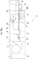
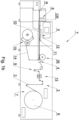
- a machine 1 for the manufacture of rods R from a continuous filling material 3 shown in Fig. 1a comprises a feeding unit 2 for feeding a strip of the filling material 3, a folding apparatus 4 for folding the strip of the filling material 3, a forming unit 5 for forming a continuous rod CR and a cutting head 6 for cutting the continuous rod CR of the tobacco industry into individual rods R.
- the machine 1 shown in Fig. 1a is adapted to manufacture rods filled with the filling material 3 and having no objects inside.
- Fig. 1b shows a machine built like the machine in Fig. 1a adapted to manufacture the rods R having inside individual objects such as capsules, tubes, etc..
- Fig. 1c shows a machine built like the machine in Fig. 1a adapted to manufacture the rods R having oblong objects inside with the length of the rod R cut from a continuous object.
- the feeding unit 2 comprises an unwinding unit 7 in which a bobbin 8 of the strip of the filling material 3 is located, and a tensioning unit 9 for maintaining a constant tension of the filling material 3.
- the forming unit 5 comprises a formatting bar 10, an adhesive apparatus 11 and a wrapping unit 12. Between the feeding unit 2 and the folding apparatus 4, there may be arranged a crimping unit 13 which is used to crimp or longitudinally cut the strip of the material 3.
- the filling material 3 is a material selected from a group comprising paper, acetate, or any other fibrous material.
- the wrapping material 14 is supplied from a supplying unit 15 and is typically in the form of a paper tape unwound from a bobbin.
- the strip of the material 3 is unwound from the bobbin 8, passes through the tensioning unit 9 and is fed to the folding apparatus 4 where the filling material 3 is folded and compacted. Before feeding the strip of the filling material 3 to the folding apparatus 4, it may be additionally crimped or cut in the crimping unit 13.
- the folding of the filling material 3 is carried out by means of inner folding surfaces and outer folding surfaces of folding elements, as is discussed below in this description.
- the folded and compacted strip of the material 3 is formed into a cylindrical shape and is wrapped with the wrapping material 14 so as to obtain a continuous rod CR, whereas the adhesive from the adhesive apparatus 11 is fed to glue the wrapping material.
- the continuous rod CR is cut into the individual rods R by means of the cutting head 6.
- the produced rods R are used to manufacture tobacco industry articles, and are cut into individual mouthpieces or segments for multi-segment filters.
- the folding apparatus 4 for folding the strip of the filling material 3 shown in simplified terms in Fig. 2a comprises an inner folding element 20 and an outer folding element 21.
- the inner folding element 20 shown with a dashed line is situated inside the outer folding element 21.
- the filling material moves in the direction T.
- the inlet of the folding apparatus 4 is marked as 40
- the outlet of the folding apparatus 4 is marked as 41.
- the folding apparatus shown in Fig. 2b is a fragment of the machine shown in Fig. 1b adapted to manufacture rods provided with individual objects.
- an inserting unit 35 for placing capsules inside the formed continuous rod CR downstream of the folding apparatus 4, there is an inserting unit 35 for placing capsules inside the formed continuous rod CR.
- Such unit may comprise, for example, an inserting wheel 44 ( Fig. 11a ) or another inserting element.
- the inner folding element 20 in the first embodiment shown in Fig. 3a and Fig. 3b has first folding surfaces 22 arranged around the axis k of the inner folding element 20.
- the inner folding element 20 comprises first ribs 24, the first folding surface 22 being the ridge of the first rib 24.
- the first folding surfaces 22 are arranged radially to the axis k, the first folding surfaces 22 being arranged circularly around an inner bounding surface 26, which means that the folding surfaces are arranged on the bounding surface 26 at angular intervals on radii extending substantially from the axis k of the inner folding element 20, the inner bounding surface 26 being shaped at least partially as a cone.
- the inner bounding surface 26 may be in the form of a cone fragment, i.e. it may be shaped partly as a cone, it may comprise flat fragments or surfaces having irregular or regular curvatures.
- Fig. 3c shows an inner folding element 20' having the first folding surfaces 22 as in Fig. 3b , the inner folding element 20' comprising profiled bars 28, the bar 28 being shaped similar to the ridge of the first rib 24. The bars 28 are fixed on rings 29 and 30.
- the outer folding element 21 is shown in the first embodiment in Fig. 4a and Fig. 4b and has second folding surfaces 23 arranged around the axis m of the outer folding element 21, the second folding surfaces 23 being positioned radially to the axis m.
- the outer folding element 21 comprises second ribs 25, the second folding surface 23 being the ridge of the second ribs 25.
- the second folding surfaces 23 are arranged circularly inside the outer bounding surface 27, whereas the outer bounding surface 27 may be partly shaped as a cone.
- the outer bounding surface 27 may be in the form of a cone fragment, i.e. it may be shaped partly as a cone, it may comprise flat fragments or surfaces having irregular or regular curvatures.
- Fig. 4c shows an outer folding element 21' having the second folding surfaces 23 as in Fig. 4b , the element 21' comprising profiled bars 31, the bar 31 being shaped similar to the ridge of the second rib 25.
- the bars 31 are fixed on rings 32 and 33.
- the folding apparatus 4 in the first embodiment shown in Fig. 5 comprises the inner folding element 20 of Fig. 3a and the outer folding element 21 of Fig. 4a positioned relative to each other so that the axis k of the inner folding element 20 and the axis m of the outer folding element 21 coincide.
- the first folding surface 22 is situated between the second folding surfaces 23, the second folding surface 23 is situated between the first folding surfaces 22.
- the first folding surfaces 22 and the second folding surfaces 23 are arranged circularly around the axes k, m, respectively. In this embodiment, both the first folding surfaces 22 and the second folding surfaces 23 are arranged uniformly around the convergent axes k, m.
- FIG. 6 shows a folding apparatus 4' in the second embodiment.
- the folding apparatus 4' comprises the inner folding element 20' shown in Fig. 3c and the outer folding element 21' shown in Fig. 4c .
- the first folding surfaces 22 and the second folding surfaces 23 are arranged similar to the first embodiment.
- the first folding surfaces 22 and the second folding surfaces 23 alternate between each other for at least a part of the distance from the inlet 40 to the outlet 41 of the folding apparatus 4, 4'.
- the first folding surfaces 22, the second folding surfaces 23, the inner bounding surface 26 and the outer bounding surface 27 form a folding channel 34.
- the strip of the filling material 3 moves in the folding channel 34 and is uniformly folded.
- the folding of the filling material 3 in Fig. 5 and in the other figures is shown in simplified terms.
- the non-coaxiality or non-parallelism of the axes k and m of the folding elements 20 and 21 can be used to non-uniformly fold the strip of the filling material 3 and to alter the degree of compaction of the material around the axes k, m in a controlled manner.
- the inner folding element 20 and the outer folding element 21, shown generally in Figs. 2a, 2b , are arranged so that the inlet side 20A ( Fig. 3b ) of the inner folding element 20 is on the inlet side 40 of the folding apparatus 4 ( Fig. 2 ).
- the inlet side 21A ( Fig. 4b ) of the outer folding element 21 is also situated on the inlet side 40 of the folding apparatus 4.
- the outlet side 20B, 21B of the inner folding element 20 and the outer folding element 21, respectively, are situated on the outlet side 41 of the folding apparatus 4.
- the first folding surface 22 is situated convergently with the axis k of the inner folding element, from the inlet 40 to the outlet 41 of the folding apparatus 4.
- the second folding surface 23 is situated convergently with the axis m of the outer folding element 21, from the inlet 40 to the outlet 41 of the folding apparatus 4, i.e. in the direction of movement T of the strip of the filling material 3.
- the height h1 of the first rib 24, measured from the inner bounding surface 26, may be variable.
- the height h1 of the first rib 24 decreases from the inlet 40 to the outlet 41 of the folding apparatus 4, the first rib 24 being rounded on the side of the inlet 40.
- the distance d of a point on the first folding surface 22 from the axis k varies so that from d1 at the inlet 40 the distance d increases from d1 to d2 and then decreases from d2 via d3 to d4 at the outlet 41.
- the height h2 of the second rib 25, measured from the outer bounding surface 27, may be variable.
- the height h2 of the second rib 25 varies from the inlet 40 to the outlet 41, namely first increasing and then decreasing, the second rib 25 being rounded on the side of the inlet 40.
- Increasing the height of the ribs allows the filling material 3 to be crimped to a greater extent, whereas the folding accomplished in such a way allows obtaining a near circular shape in the cross-section of the continuous rod CR.
- increasing the number of ribs allows folding the filling material to a greater extent and obtaining a near-circular shape in the cross-section of the continuous rod CR.
- the strip of the filling material 3 is supplied to the folding apparatus 4 in a flat form and is re-formed from a flat configuration to a substantially circular configuration around the axes k, m in the folding channel 34 as shown in Fig. 5 , the strip of the filling material 3 being situated between the first folding surfaces 22 and the second folding surfaces 23.
- the inner folding surfaces 22 are arranged uniformly around the axis k and the outer folding surfaces 23 are arranged uniformly around the axis m, in this case around the same axis.
- an inner folding element 20" is provided with the first ribs 24' which are non-uniformly arranged around the axis k of the inner folding element 20".
- the thickness g of the first rib 24 is variable in the direction of movement T of the filling material 3, i.e. in a direction substantially parallel to the axis k.
- the thickness g on the side of the inlet 40 is greater than the thickness g' on the side of the outlet 41.
- the thickness g of the first rib 24 may be variable in a direction transverse to the direction of movement T of the filling material 3, i.e. in a direction substantially perpendicular to the axis k.
- the thickness g" (shown in Fig.
- Fig. 8 shows an outer folding element 21" provided with the second ribs 25 which have a variable thickness f.
- the thickness f of the second rib 25 is variable in the direction of movement T of the filling material 3, i.e. in a direction substantially parallel to the axis m.
- the thickness f on the side of the inlet 40 is greater than the thickness f" on the side of the outlet 41.
- the thickness f of the second rib 25 is variable in a direction transverse to the direction of movement T of the filling material 3, i.e. in a direction substantially perpendicular to the axis m.
- the thickness f at the outer bounding surface 27 is greater than the thickness f' on the side of the axis m.
- the first ribs 24 are non-uniformly arranged around the axis k.
- the second ribs 25 are also non-uniformly arranged around the axis m.
- the arrangement of the second ribs 25 of the outer folding element 21" is aligned with the arrangement of the first ribs 24 of the inner folding element 20" of Fig. 7 .
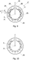
- the inner folding element 20" and the outer folding element 21" are arranged together in Fig. 9 , with the axis k and the axis m coinciding, while in Fig.
- the inner folding element 20" and the outer folding element 21" arranged together so that the axis k and the axis m are not coaxial, the axis k of the inner folding element 20" being situated above the axis m of the outer folding element 21".
- a separating element 43 which can also be seen in Fig. 9 and Fig. 10 .
- the separating element 43 is situated above the axis or tangentially to the axis k of the inner folding element 20 from the inlet 40 into the forming channel 42.
- the separating element 43 is in the form of a plate of decreasing width, i.e. of a width close to the radius of the outer bounding surface 27 at the inlet 40 and further of decreasing width to the outlet 41 and further into the forming channel 42.
- the separating element 43 reaches the inserting wheel 44 for inserting individual objects 45, for example capsules, into the strip of the filling material 3.
- the separating element 43 separates the edges 3A, 3B the strip of the filling material 3 both in the folding apparatus 4 and in the forming channel 42.
- the use of the separating element 43 facilitates the insertion of the capsules 45 by separating the edges 3A, 3B.
- the folding apparatus 4 can be provided with a guiding element along which the filling material 3 is conveyed before feeding it for folding .
- Fig. 11a and Fig. 11b show a non-rotational guiding element 46 which is in the form of an arc.
- the non-rotational guiding element 46 has an adjustable position and is adapted to alter its position in a direction transverse to the axis k of the inner folding element 20 or the axis m of the outer folding element 21.
- the non-rotational guiding element 46 is mounted on a bracket 47 which is provided with an adjustment in the direction S, i.e. in a direction transverse to the axis k or m of the folding elements 20, 21.
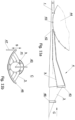
- FIG. 12b show a rotational guiding element 48 with a horizontal axis of rotation p, the surface 48A of the rotational guiding element 48 having an arched or near elliptical shape in cross-section.
- the rotational guiding element 48 is also provided with an adjustment in the direction S.
- An alteration in the position of the non-rotational guiding element 46 or the rotational guiding element 48 has the effect of varying the degree of compaction of the filling material 3 in the continuous rod CR, a movement of the guiding element 46, 48 downwards causes an increase in compaction in the lower part of the folding apparatus, i.e. in the area of the edges 3A, 3B.
- an inserting wheel 49 for placing the tubes 50 in the continuous rod CR is shown.
- the separating element 43 facilitates the insertion of the tubes 50 between the fibres of the filling material 3.
- the folding apparatus 4" shown in Fig. 13a is a fragment of the machine shown in Fig. 1c , adapted to manufacture the rods R provided with oblong objects.
- upstream of the folding apparatus 4 there is a supplying unit 36 for supplying the continuous object 50 into the continuous rod CR being formed.
- the continuous object 50 may have a transverse circular, oval, polygonal, multi-armed or any other cross-section.
- the continuous object 50 is in the form of a tube.
- Fig. 13b shows an embodiment of the folding apparatus 4" adapted to fold the filling material 3 around the continuous object 50 fed centrally through by the inner folding element 20".
- the continuous object 50 is fed through an opening 51 in the inner folding element 20".
- the folding apparatus 4" can be adapted to any other cross-section of the continuous object 50.
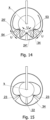
- Fig. 14 shows an embodiment wherein the first ribs 24' and the second ribs 25' have an increased height at the side of the inlet 40 relative to the first ribs 24 and the second ribs 25 in the previous embodiments.
- the first folding surfaces 22 and the second folding surfaces 23 are shaped in any of the ways discussed above.
- the first rib 24' may be provided with a slidably mounted foot 53 and is adapted to an alteration in position according to the direction U around the axis k.
- the second rib 25' may be provided with a slidably mounted foot 54 and is adapted to an alteration in position according to the direction U around the axis m.
- the variation in position of the first folding surfaces 22 and/or the second folding surfaces 23 around the axis k of the inner folding element 20 or the axis m of the outer folding element 21 may be used in any of the embodiments discussed above.
- Fig. 15 shows an embodiment wherein the folding apparatus is provided with a single first folding surface 22 and two second folding surfaces 23, the first folding surface 22 being positioned between the two second folding surfaces 23.
- An embodiment wherein a single second folding surface 23 is situated between the two first folding surfaces 22 is also possible.
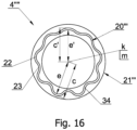
- Fig. 16 shows a folding apparatus 4 ⁇ comprising the inner folding element 20′′′ and the outer folding element 21′′′ .
- the first folding surfaces 22 of the inner folding element 20′′′ and the second folding surfaces 23 of the outer folding element 21" are arranged such that the folding channel 34 has a width that varies over a small range or is substantially constant.
- the position of the first folding surfaces 22 and the second folding surfaces 23, and thus of the folding channel 34, may be variable.
- the position of the first folding surfaces 22 is defined by the distance e from the axis k.
- the distance e from the axis k in the lower part of the folding apparatus 4 ⁇ is greater than the distance e' in the upper part of the folding apparatus 4 ⁇ .
- the distance e of the successive inner folding surfaces 22 gradually decreases to e'.
- the distance e may be constant for all first folding surfaces 22.
- the position of the second folding surfaces 23 is defined by the distance c from the axis m.
- the distance c from the axis m in the lower part of the folding apparatus 4′′′ is greater than the distance c' in the upper part of the folding apparatus 4"".
- the distance c of the successive inner folding surfaces 23 gradually deceases to c'.
- the distance c can be constant for all second folding surfaces 23.
- the folding apparatus 4 ⁇ can be used for the low-strength filling material 3.
Landscapes
- Engineering & Computer Science (AREA)
- Mechanical Engineering (AREA)
- Manufacturing Of Cigar And Cigarette Tobacco (AREA)
- Cigarettes, Filters, And Manufacturing Of Filters (AREA)
- Containers And Plastic Fillers For Packaging (AREA)
Abstract
Description
- The object of the invention is a folding apparatus for folding a strand of filling material placed in a continuous rod of the tobacco industry.
- The invention is used in the tobacco industry to manufacture paper filters.
- In the tobacco industry, a commonly used method of manufacturing cigarette filters consists in forming a continuous rod filled with a filtering material and cutting such rod into individual rods from which either individual mouthpieces or individual segments are finally cut off and used to manufacture multi-segment filters. The filling material used to manufacture the continuous rod is usually a fibrous material. For many years, paper and acetate fibres have been commonly used, with the filling material usually being in the form of a strand. A problem to be solved by manufacturers of the abovementioned rods is to achieve a cylindrical rod shape. A shape error can be easily seen at the ends of the rod which should be circular, the shape of the end can be oval, and often the ends are irregular, which depends on an uneven arrangement of the filling material inside the rod, which depends on random folding of the material during the feeding of the filling material before the continuous rod is formed. The problem to obtain a circular cross-section is even greater when objects are placed inside the continuous rod. Single objects are commonly used, for example aroma capsules, tubes. Continuous objects are commonly used, for example fibres impregnated with aromatic substances. It is particularly difficult to achieve uniform folding and compaction of the material when the objects are inserted transversely to the direction of movement of the strand of filter material. For each object inserted, a uniform distribution of the filling material around the objects and/or between the objects must be achieved. So the purpose of the present invention is to correctly prepare the strip prior to object insertion.
- In the prior art, devices for folding a paper strip prior to compacting it in the continuous rod production process are known. Such a solution is presented in
CN105745069A which discloses an apparatus for processing a continuous strip comprising a crimped structure to be used in the production of a rod-like article, such as a filter element for a smoking article. The apparatus comprises a first roller and a second roller. The first roller and the second roller each contain several circumferentially running cams. Furthermore, the first roller and the second roller are arranged such that the circumferential cam of the first roller and the circumferential cam of the second roller are connected to each other. After conveying a continuous sheet with a crimped structure between the first roller and the second roller, the continuous sheet with the crimped structure may have an overlapping crimped structure and remain continuous, and a corrugated structure extending in the longitudinal direction of the strip. - An apparatus maintaining a separation between individual strips of crimped paper strip such as in
EP3918929A1 is also known. The body of the guiding unit has a funnel-like shape. Inside the ring, separating elements are arranged in a converging channel, with at least one separating element designed to separate at least two strips is situated along the guiding unit. The upper separating element runs from the inlet to the outlet inside the compressing unit and has the shape of an oblong plate whose edges are convergent. The lower separating elements are similar in shape to the upper separating element, i.e. they are oblong and have convergent edges. - The purpose of the present invention is to develop an apparatus for folding a filling material used in the tobacco industry which will allow filling a continuous rod being manufactured and the rods cut from it so as to obtain a near-circular shape in cross-section, both when the manufactured continuous rod is filled only with the filling material and when separate objects, for example spherical objects such as capsules or oblong objects such as tubes, are placed inside the continuous rod and the individual rods. The expectation to obtain a circular shape in the cross-section of the continuous rod also applies to placing a continuous object, for example a tube, a thin rod, a string or a thread, inside the rod. An additional expectation when placing various objects in the continuous rod is to place the object centrally in the continuous rod.
- The object of the invention is a folding apparatus for folding a strip of filling material placed in a continuous rod of the tobacco industry, comprising an inner folding element having first folding surfaces situated radially around the axis of the inner folding element and adapted to crimp the strip of the filling material, an outer folding element having second folding surfaces situated radially around the axis of the outer folding element and adapted to crimp the strip of the filling material. The first folding surfaces situated radially around the axis of the inner folding element are arranged between the second folding surfaces situated radially around the axis of the outer folding element.
- The apparatus according to the invention is further characterised in that the first folding surfaces are situated convergently with the axis of the inner folding element, from the inlet to the outlet of the folding apparatus, and the second folding surfaces are situated convergently with the axis of the outer folding element, from the inlet to the outlet of the folding apparatus, the axis of the inner folding element being situated coaxially with the axis of the outer folding element.
- The apparatus according to the invention is further characterised in that the first folding surfaces are situated convergently with the axis of the inner folding element, from the inlet to the outlet of the folding apparatus, and the second folding surfaces are situated convergently with the axis of the outer folding element, from the inlet to the outlet of the folding apparatus, the axis of the inner folding element being situated non-coaxially with the axis of the outer folding element.
- The apparatus according to the invention is further characterised in that the distance of the first folding surface from the axis of the first folding element in the direction from the inlet to the outlet increases, reaches a maximum height, and then decreases.
- The apparatus according to the invention is further characterised in that the angle of convergence of the second folding surface with the axis of the second folding element decreases in the direction from the inlet to the outlet.
- The apparatus according to the invention is further characterised in that the first folding surfaces are uniformly arranged around the axis of the inner folding element and/or the second folding surfaces are uniformly arranged around the axis of the outer folding element.
- The apparatus according to the invention is further characterised in that the first folding surfaces are non-uniformly arranged around the axis of the inner folding element and/or the second folding surfaces are non-uniformly arranged around the axis of the outer folding element.
- The apparatus according to the invention is further characterised in that the first folding surfaces and the second folding surfaces are arranged alternately between each other for at least a part of the distance from the inlet to the outlet of the folding apparatus.
- The apparatus according to the invention is further characterised in that the inner folding element comprises first ribs and the first folding surfaces are the ridges of the first ribs and/or the outer folding element comprises second ribs, the second folding surfaces being the ridges of the second ribs.
- The apparatus according to the invention is further characterised in that the thickness of the first ribs and/or the thickness of the second ribs varies in a direction perpendicular and/or parallel to the axis of the first folding element and/or the second folding element, respectively.
- The apparatus according to the invention is further characterised in that the inner folding element comprises an inner bounding surface shaped at least partially conically and/or the outer folding element comprises an outer bounding surface shaped at least partially conically.
- The apparatus according to the invention is further characterised by being provided with a guiding element for guiding a strip of the filling material with an adjustable position in a transverse direction to the axis of the inner folding element or the axis of the outer folding element.
- The apparatus according to the invention is further characterised in that the guiding element is in the form of a rotating element with a horizontal axis of rotation, the axial cross-section of the surface of the rotatable guiding element having an arched or near elliptical shape.
- The apparatus according to the invention is further characterised by comprising a separating element situated above the axis of the inner folding element from the inlet to the outlet of the apparatus.
- The object of the invention is further an apparatus for manufacturing tobacco industry rods, comprising a feeding unit for feeding the filling material, an apparatus for folding the filling material according to one of the abovementioned variants, an apparatus for feeding a wrapping material, a forming unit for forming the continuous rod, a cutting head for cutting the continuous rod into the rods.
- An advantage of the apparatus is that it allows controlled folding of a single paper strip during the compaction of the strip in the folding apparatus. Further advantages of the invention include uniform folding of the filling material and obtaining a uniform density of the filling material in the manufactured rods both having no objects inside and having objects inside. The apparatus makes it possible to adapt the folding of the filling material both for continuous objects with a substantially circular cross-section and for objects with an oval, irregular, polygonal cross-section, in general with any cross-section.
- The object of the invention is shown in more detail in a preferred embodiment in a drawing in which:
- Fig. 1a
- shows a machine for the manufacture of rods with no objects inside,
- Fig. 1b
- shows a machine for the manufacture of rods with individual objects inside,
- Fig. 1c
- shows a machine for the manufacture of rods having oblong objects inside,
- Fig. 2a
- shows an enlarged section of the machine of
Fig. 1a with a folding apparatus, - Fig. 2b
- shows an enlarged section of the machine of
Fig. 1b with the folding apparatus, - Fig. 3a
- shows an inner folding element in the first embodiment in a view from the outlet side of the folding apparatus,
- Fig. 3b
- shows a cross-section through the inner folding element of
Fig. 3a , - Fig. 3c
- shows a component of the inner folding element in the second embodiment,
- Fig. 4a
- shows an outer folding element in the first embodiment in a view from the inlet side of the folding apparatus,
- Fig. 4b
- shows an axial section through the outer folding element of
Fig. 4a , - Fig. 4c
- shows a component of the outer folding element in the second embodiment,
- Fig. 5
- shows the folding apparatus in the first embodiment comprising the inner folding element of
Fig. 3a and the outer folding element ofFig. 4a , - Fig. 6
- shows the folding apparatus in the second embodiment comprising the inner folding element of
Fig. 3c and the outer folding element ofFig. 4c , - Fig. 7
- shows the inner folding element in the third embodiment in a view from the outlet side of the folding apparatus,
- Fig. 8
- shows the outer folding element in the third embodiment in a view from the inlet side of the folding apparatus,
- Fig. 9 and Fig. 10
- show the folding apparatus in the third embodiment,
- Fig. 11a and Fig. 11b
- show a section of the machine for the manufacture of rods, including the folding apparatus provided with a fixed guiding element,
- Fig. 12a, b, c
- show a section of the machine for the manufacture of rods, including the folding apparatus provided with a rotating guiding element,
- Fig. 13a, b
- show a section of the machine for the manufacture of rods, including the folding apparatus in the fourth embodiment for folding a strip of material around a continuous element,
- Fig. 14
- shows the folding apparatus in the fifth embodiment,
- Fig. 15
- shows the folding apparatus in the sixth embodiment,
- Fig. 16
- shows the folding apparatus in the seventh embodiment.
- A
machine 1 for the manufacture of rods R from acontinuous filling material 3 shown inFig. 1a comprises afeeding unit 2 for feeding a strip of the fillingmaterial 3, afolding apparatus 4 for folding the strip of the fillingmaterial 3, a formingunit 5 for forming a continuous rod CR and a cuttinghead 6 for cutting the continuous rod CR of the tobacco industry into individual rods R. Themachine 1 shown inFig. 1a is adapted to manufacture rods filled with the fillingmaterial 3 and having no objects inside.Fig. 1b shows a machine built like the machine inFig. 1a adapted to manufacture the rods R having inside individual objects such as capsules, tubes, etc..Fig. 1c shows a machine built like the machine inFig. 1a adapted to manufacture the rods R having oblong objects inside with the length of the rod R cut from a continuous object. - The
feeding unit 2 comprises an unwindingunit 7 in which abobbin 8 of the strip of the fillingmaterial 3 is located, and atensioning unit 9 for maintaining a constant tension of the fillingmaterial 3. The formingunit 5 comprises aformatting bar 10, anadhesive apparatus 11 and awrapping unit 12. Between thefeeding unit 2 and thefolding apparatus 4, there may be arranged a crimpingunit 13 which is used to crimp or longitudinally cut the strip of thematerial 3. The fillingmaterial 3 is a material selected from a group comprising paper, acetate, or any other fibrous material. The wrappingmaterial 14 is supplied from a supplyingunit 15 and is typically in the form of a paper tape unwound from a bobbin. - The strip of the
material 3 is unwound from thebobbin 8, passes through thetensioning unit 9 and is fed to thefolding apparatus 4 where the fillingmaterial 3 is folded and compacted. Before feeding the strip of the fillingmaterial 3 to thefolding apparatus 4, it may be additionally crimped or cut in the crimpingunit 13. The folding of the fillingmaterial 3 is carried out by means of inner folding surfaces and outer folding surfaces of folding elements, as is discussed below in this description. The folded and compacted strip of thematerial 3 is formed into a cylindrical shape and is wrapped with the wrappingmaterial 14 so as to obtain a continuous rod CR, whereas the adhesive from theadhesive apparatus 11 is fed to glue the wrapping material. The continuous rod CR is cut into the individual rods R by means of the cuttinghead 6. The produced rods R are used to manufacture tobacco industry articles, and are cut into individual mouthpieces or segments for multi-segment filters. - The
folding apparatus 4 for folding the strip of the fillingmaterial 3 shown in simplified terms inFig. 2a comprises aninner folding element 20 and anouter folding element 21. Theinner folding element 20 shown with a dashed line is situated inside theouter folding element 21. The filling material moves in the direction T. The inlet of thefolding apparatus 4 is marked as 40, the outlet of thefolding apparatus 4 is marked as 41. The folding apparatus shown inFig. 2b is a fragment of the machine shown inFig. 1b adapted to manufacture rods provided with individual objects. In the embodiment shown, downstream of thefolding apparatus 4, there is an insertingunit 35 for placing capsules inside the formed continuous rod CR. Such unit may comprise, for example, an inserting wheel 44 (Fig. 11a ) or another inserting element. - The
inner folding element 20 in the first embodiment shown inFig. 3a and Fig. 3b has first folding surfaces 22 arranged around the axis k of theinner folding element 20. In the shown embodiment of thefolding apparatus 4, theinner folding element 20 comprisesfirst ribs 24, thefirst folding surface 22 being the ridge of thefirst rib 24. The first folding surfaces 22 are arranged radially to the axis k, the first folding surfaces 22 being arranged circularly around aninner bounding surface 26, which means that the folding surfaces are arranged on the boundingsurface 26 at angular intervals on radii extending substantially from the axis k of theinner folding element 20, theinner bounding surface 26 being shaped at least partially as a cone. Theinner bounding surface 26 may be in the form of a cone fragment, i.e. it may be shaped partly as a cone, it may comprise flat fragments or surfaces having irregular or regular curvatures.Fig. 3c shows an inner folding element 20' having the first folding surfaces 22 as inFig. 3b , the inner folding element 20' comprising profiledbars 28, thebar 28 being shaped similar to the ridge of thefirst rib 24. Thebars 28 are fixed onrings outer folding element 21 is shown in the first embodiment inFig. 4a and Fig. 4b and has second folding surfaces 23 arranged around the axis m of theouter folding element 21, the second folding surfaces 23 being positioned radially to the axis m. Theouter folding element 21 comprisessecond ribs 25, thesecond folding surface 23 being the ridge of thesecond ribs 25. The second folding surfaces 23 are arranged circularly inside theouter bounding surface 27, whereas theouter bounding surface 27 may be partly shaped as a cone. Theouter bounding surface 27 may be in the form of a cone fragment, i.e. it may be shaped partly as a cone, it may comprise flat fragments or surfaces having irregular or regular curvatures.Fig. 4c shows an outer folding element 21' having the second folding surfaces 23 as inFig. 4b , the element 21' comprising profiledbars 31, thebar 31 being shaped similar to the ridge of thesecond rib 25. Thebars 31 are fixed onrings - The
folding apparatus 4 in the first embodiment shown inFig. 5 comprises theinner folding element 20 ofFig. 3a and theouter folding element 21 ofFig. 4a positioned relative to each other so that the axis k of theinner folding element 20 and the axis m of theouter folding element 21 coincide. Thefirst folding surface 22 is situated between the second folding surfaces 23, thesecond folding surface 23 is situated between the first folding surfaces 22. The first folding surfaces 22 and the second folding surfaces 23 are arranged circularly around the axes k, m, respectively. In this embodiment, both the first folding surfaces 22 and the second folding surfaces 23 are arranged uniformly around the convergent axes k, m. It is possible to position the axes k and m at a small angle or non-coaxially parallel to each other.Fig. 6 shows a folding apparatus 4' in the second embodiment. The folding apparatus 4' comprises the inner folding element 20' shown inFig. 3c and the outer folding element 21' shown inFig. 4c . The first folding surfaces 22 and the second folding surfaces 23 are arranged similar to the first embodiment. The first folding surfaces 22 and the second folding surfaces 23 alternate between each other for at least a part of the distance from theinlet 40 to theoutlet 41 of thefolding apparatus 4, 4'. - The first folding surfaces 22, the second folding surfaces 23, the
inner bounding surface 26 and theouter bounding surface 27 form afolding channel 34. In the embodiment shown inFig. 5 , the strip of the fillingmaterial 3 moves in thefolding channel 34 and is uniformly folded. The folding of the fillingmaterial 3 inFig. 5 and in the other figures is shown in simplified terms. The non-coaxiality or non-parallelism of the axes k and m of thefolding elements material 3 and to alter the degree of compaction of the material around the axes k, m in a controlled manner. - The
inner folding element 20 and theouter folding element 21, shown generally inFigs. 2a, 2b , are arranged so that theinlet side 20A (Fig. 3b ) of theinner folding element 20 is on theinlet side 40 of the folding apparatus 4 (Fig. 2 ). Theinlet side 21A (Fig. 4b ) of theouter folding element 21 is also situated on theinlet side 40 of thefolding apparatus 4. Theoutlet side inner folding element 20 and theouter folding element 21, respectively, are situated on theoutlet side 41 of thefolding apparatus 4. Thefirst folding surface 22 is situated convergently with the axis k of the inner folding element, from theinlet 40 to theoutlet 41 of thefolding apparatus 4. Thesecond folding surface 23 is situated convergently with the axis m of theouter folding element 21, from theinlet 40 to theoutlet 41 of thefolding apparatus 4, i.e. in the direction of movement T of the strip of the fillingmaterial 3. The height h1 of thefirst rib 24, measured from theinner bounding surface 26, may be variable. The height h1 of thefirst rib 24 decreases from theinlet 40 to theoutlet 41 of thefolding apparatus 4, thefirst rib 24 being rounded on the side of theinlet 40. The distance d of a point on thefirst folding surface 22 from the axis k varies so that from d1 at theinlet 40 the distance d increases from d1 to d2 and then decreases from d2 via d3 to d4 at theoutlet 41. The height h2 of thesecond rib 25, measured from theouter bounding surface 27, may be variable. The height h2 of thesecond rib 25 varies from theinlet 40 to theoutlet 41, namely first increasing and then decreasing, thesecond rib 25 being rounded on the side of theinlet 40. Increasing the height of the ribs allows the fillingmaterial 3 to be crimped to a greater extent, whereas the folding accomplished in such a way allows obtaining a near circular shape in the cross-section of the continuous rod CR. Similarly, increasing the number of ribs allows folding the filling material to a greater extent and obtaining a near-circular shape in the cross-section of the continuous rod CR. - The strip of the filling
material 3 is supplied to thefolding apparatus 4 in a flat form and is re-formed from a flat configuration to a substantially circular configuration around the axes k, m in thefolding channel 34 as shown inFig. 5 , the strip of the fillingmaterial 3 being situated between the first folding surfaces 22 and the second folding surfaces 23. The inner folding surfaces 22 are arranged uniformly around the axis k and the outer folding surfaces 23 are arranged uniformly around the axis m, in this case around the same axis. - In the embodiment shown in
Fig. 7 , aninner folding element 20" is provided with the first ribs 24' which are non-uniformly arranged around the axis k of theinner folding element 20". The thickness g of thefirst rib 24 is variable in the direction of movement T of the fillingmaterial 3, i.e. in a direction substantially parallel to the axis k. The thickness g on the side of theinlet 40 is greater than the thickness g' on the side of theoutlet 41. Furthermore, the thickness g of thefirst rib 24 may be variable in a direction transverse to the direction of movement T of the fillingmaterial 3, i.e. in a direction substantially perpendicular to the axis k. The thickness g" (shown inFig. 9 ) at theinner bounding surface 26 is greater than the thickness g on the ridge of therib 24.Fig. 8 shows anouter folding element 21" provided with thesecond ribs 25 which have a variable thickness f. The thickness f of thesecond rib 25 is variable in the direction of movement T of the fillingmaterial 3, i.e. in a direction substantially parallel to the axis m. The thickness f on the side of theinlet 40 is greater than the thickness f" on the side of theoutlet 41. Furthermore, the thickness f of thesecond rib 25 is variable in a direction transverse to the direction of movement T of the fillingmaterial 3, i.e. in a direction substantially perpendicular to the axis m. The thickness f at theouter bounding surface 27 is greater than the thickness f' on the side of the axis m. Thefirst ribs 24 are non-uniformly arranged around the axis k. Thesecond ribs 25 are also non-uniformly arranged around the axis m. The arrangement of thesecond ribs 25 of theouter folding element 21" is aligned with the arrangement of thefirst ribs 24 of theinner folding element 20" ofFig. 7 . Theinner folding element 20" and theouter folding element 21" are arranged together inFig. 9 , with the axis k and the axis m coinciding, while inFig. 10 theinner folding element 20" and theouter folding element 21" arranged together so that the axis k and the axis m are not coaxial, the axis k of theinner folding element 20" being situated above the axis m of theouter folding element 21". By arranging theelements 20" and 21" in this way, a higher compaction in the upper part of thefolding channel 34 is achieved due to increased folding of the fillingmaterial 3. When the axis k of theinner folding element 20" is situated below the axis m of theouter folding element 21", a higher compaction in the lower part of thefolding channel 34 is achieved. By adjusting the position of theinner folding element 20" relative to theouter folding element 21", a gradual variation in the compaction of the fillingmaterial 3 in the manufactured continuous rod CR can be achieved. The uniformly arranged folding of the fillingmaterial 3 makes it possible to obtain a central position of the objects inside the continuous rod CR. - In
Fig. 11a , in a cross-section along the axis r of a formingchannel 42, there can be seen a separatingelement 43 which can also be seen inFig. 9 and Fig. 10 . The separatingelement 43 is situated above the axis or tangentially to the axis k of theinner folding element 20 from theinlet 40 into the formingchannel 42. The separatingelement 43 is in the form of a plate of decreasing width, i.e. of a width close to the radius of theouter bounding surface 27 at theinlet 40 and further of decreasing width to theoutlet 41 and further into the formingchannel 42. Further in the direction of movement T of the strip of thematerial 3, the separatingelement 43 reaches the insertingwheel 44 for insertingindividual objects 45, for example capsules, into the strip of the fillingmaterial 3. The separatingelement 43 separates theedges material 3 both in thefolding apparatus 4 and in the formingchannel 42. The use of the separatingelement 43 facilitates the insertion of thecapsules 45 by separating theedges - The
folding apparatus 4 can be provided with a guiding element along which the fillingmaterial 3 is conveyed before feeding it for folding .Fig. 11a and Fig. 11b show anon-rotational guiding element 46 which is in the form of an arc. Thenon-rotational guiding element 46 has an adjustable position and is adapted to alter its position in a direction transverse to the axis k of theinner folding element 20 or the axis m of theouter folding element 21. Thenon-rotational guiding element 46 is mounted on abracket 47 which is provided with an adjustment in the direction S, i.e. in a direction transverse to the axis k or m of thefolding elements Fig. 12a and Fig. 12b show arotational guiding element 48 with a horizontal axis of rotation p, thesurface 48A of therotational guiding element 48 having an arched or near elliptical shape in cross-section. Therotational guiding element 48 is also provided with an adjustment in the direction S. An alteration in the position of thenon-rotational guiding element 46 or therotational guiding element 48 has the effect of varying the degree of compaction of the fillingmaterial 3 in the continuous rod CR, a movement of the guidingelement edges Fig. 12a , an insertingwheel 49 for placing thetubes 50 in the continuous rod CR is shown. As in the case of thecapsules 45, the separatingelement 43 facilitates the insertion of thetubes 50 between the fibres of the fillingmaterial 3. - The
folding apparatus 4" shown inFig. 13a is a fragment of the machine shown inFig. 1c , adapted to manufacture the rods R provided with oblong objects. In the embodiment shown, upstream of thefolding apparatus 4, there is a supplyingunit 36 for supplying thecontinuous object 50 into the continuous rod CR being formed. Thecontinuous object 50 may have a transverse circular, oval, polygonal, multi-armed or any other cross-section. In the embodiment shown, thecontinuous object 50 is in the form of a tube.Fig. 13b shows an embodiment of thefolding apparatus 4" adapted to fold the fillingmaterial 3 around thecontinuous object 50 fed centrally through by theinner folding element 20". Thecontinuous object 50 is fed through anopening 51 in theinner folding element 20". Thefolding apparatus 4" can be adapted to any other cross-section of thecontinuous object 50. -
Fig. 14 shows an embodiment wherein the first ribs 24' and the second ribs 25' have an increased height at the side of theinlet 40 relative to thefirst ribs 24 and thesecond ribs 25 in the previous embodiments. The first folding surfaces 22 and the second folding surfaces 23 are shaped in any of the ways discussed above. The first rib 24' may be provided with a slidably mountedfoot 53 and is adapted to an alteration in position according to the direction U around the axis k. The second rib 25' may be provided with a slidably mountedfoot 54 and is adapted to an alteration in position according to the direction U around the axis m. The variation in position of the first folding surfaces 22 and/or the second folding surfaces 23 around the axis k of theinner folding element 20 or the axis m of theouter folding element 21 may be used in any of the embodiments discussed above. Thus, it is possible to shape thefolding channel 34 variously and in any manner and to adapt the folding of the filling material to the production requirements. -
Fig. 15 shows an embodiment wherein the folding apparatus is provided with a singlefirst folding surface 22 and two second folding surfaces 23, thefirst folding surface 22 being positioned between the two second folding surfaces 23. An embodiment wherein a singlesecond folding surface 23 is situated between the two first folding surfaces 22 is also possible. -
Fig. 16 shows a folding apparatus 4ʺʺ comprising theinner folding element 20‴ and theouter folding element 21‴. The first folding surfaces 22 of theinner folding element 20‴ and the second folding surfaces 23 of theouter folding element 21" are arranged such that thefolding channel 34 has a width that varies over a small range or is substantially constant. The position of the first folding surfaces 22 and the second folding surfaces 23, and thus of thefolding channel 34, may be variable. The position of the first folding surfaces 22 is defined by the distance e from the axis k. The distance e from the axis k in the lower part of the folding apparatus 4ʺʺ is greater than the distance e' in the upper part of the folding apparatus 4ʺʺ. In the embodiment shown, the distance e of the successive inner folding surfaces 22 gradually decreases to e'. The distance e may be constant for all first folding surfaces 22. The position of the second folding surfaces 23 is defined by the distance c from the axis m. The distance c from the axis m in the lower part of thefolding apparatus 4‴ is greater than the distance c' in the upper part of thefolding apparatus 4"". In the embodiment shown, the distance c of the successive inner folding surfaces 23 gradually deceases to c'. The distance c can be constant for all second folding surfaces 23. The folding apparatus 4ʺʺ can be used for the low-strength filling material 3.List of designations 41 outlet of folding apparatus 1 rod manufacturing machine 42 forming channel 2 feeding unit 43 separating element 3 filling material 44 object/capsule inserting wheel 3A, 3B edges of strip of filling material 45 inserted objects, capsules 4, 4' ,4", 4‴, 4"" folding apparatus 46 non-rotational guiding element 5 forming unit 47 bracket of guiding element 6 cutting head 48 rotational guiding element 7 unwinding unit 49 tube inserting wheel 8 bobbin of material strip 50 inserted continuous objects, tubes 9 tensioning unit 51 hole in inner folding element 20'" 10 format bar 53 foot of first rib 24' 11 adhesive apparatus 54 foot of second rib 25' 12 wrapping unit 13 crimping unit d distance of first folding surface from axis k 14 wrapping material e distance of first folding surface from axis k 15 supplying unit c distance of second folding surface from axis m 20, 20', 20", 20'" inner folding element 20A inlet side of inner folding element h1 height of first rib 20B outlet side of inner folding element h2 height of second rib 21, 21', 21ʺ,21ʺ outer folding element g thickness of first rib on inlet side 21A inlet side of outer folding element g' thickness of first rib on outlet side 21B outlet side of outer folding element gʺ thickness of first rib at inner bounding surface f thickness of second rib 22 first folding surfaces f' thickness of second rib on inlet side 23 second folding surfaces f" thickness of second rib on outlet side 24, 24' first ribs 25, 25' second ribs k axis of inner folding element 26 inner bounding surface m axis of outer folding element 27 outer bounding surface p horizontal axis of rotation of rotational guiding element 28 profiled bars 29, 30 fastening rings r axis of forming channel 31 profiled bars 32, 33 fastening rings S direction of guiding element adjustment 34 folding channel T direction of movement of filling material 35 inserting unit U direction of movement of ribs 36 supplying unit CR continuous rod 40 inlet of folding apparatus R rod
Claims (15)
- A folding apparatus (4, 4', 4", 4", 4"") for folding a strip of filling material (3) placed in a continuous rod (CR) of the tobacco industry, comprisingan inner folding element (20, 20', 20", 20‴) having first folding surfaces (22) situated radially around the axis (k) of the inner folding element (20, 20', 20", 20'") adapted to fold the strip of the filling material (3),an outer folding element (21, 21', 21ʺ, 21‴) having second folding surfaces (23) situated radially around the axis (m) of the outer folding element (21) adapted to fold the strip of the filling material (3),whereas the first folding surfaces (22) situated radially around the axis (k) of the inner folding element (20, 20', 20", 20"') are arranged between the second folding surfaces (23) situated radially around the axis (m) of the outer folding element (21, 21', 21ʺ, 20‴).
- The apparatus as in claim 1, characterised in that the first folding surfaces (22) are situated convergently with the axis (k) of the inner folding element (20, 20', 20", 20‴), from the inlet (40) to the outlet (41) of the folding apparatus (4, 4', 4", 4‴, 4""), and the second folding surfaces (23) are situated convergently with the axis (m) of the outer folding element (21, 21', 21", 21‴), from the inlet (40) to the outlet (41) of the folding apparatus (4, 4', 4", 4‴, 4ʺʺ), the axis (k) of the inner folding element (20, 20', 20", 20‴ ) being situated coaxially with the axis (m) of the outer folding element (21, 21', 21", 21‴).
- The apparatus as in claim 1, characterised in that the first folding surfaces (22) are situated convergently with the axis (k) of the inner folding element (20, 20', 20", 20"'), from the inlet (40) to the outlet (41) of the folding apparatus (4, 4', 4", 4‴, 4ʺʺ), and the second folding surfaces (23) are situated convergently with the axis (m) of the outer folding element (21, 21', 21", 21‴), from the inlet (40) to the outlet (41) of the folding apparatus (4, 4', 4", 4‴, 4ʺʺ), the axis (k) of the inner folding element (20, 20', 20", 20") being arranged non-coaxially with the axis (m) of the outer folding element (21, 21', 21ʺ, 21‴)
- The apparatus as in claims 1 to 3, characterised in that the distance (d) of the first folding surface (22) from the axis (k) of the first folding element (20, 20', 20", 20‴) in the direction from the inlet (40) to the outlet (41) increases, reaches a maximum height, and then decreases.
- The apparatus as in any of the claims 1 to 4, characterised in that the angle of convergence (a) of the second folding surface (23) with the axis (m) of the second folding element (21, 21', 21ʺ, 21‴) decreases in the direction from the inlet (40) to the outlet (41).
- The apparatus as in any of the claims 1 to 5, characterised in that the first folding surfaces (22) are uniformly arranged around the axis (k) of the inner folding element (20, 20', 20", 20"') and/or the second folding surfaces (23) are uniformly arranged around the axis (m) of the outer folding element (21, 21', 21ʺ, 21‴).
- The apparatus as in any of the claims 1 to 5, characterised in that the first folding surfaces (22) are non-uniformly arranged around the axis (k) of the inner folding element (20, 20', 20", 20"') and/or the second folding surfaces (23) are non-uniformly arranged around the axis (m) of the outer folding element (21, 21', 21ʺ, 21‴).
- The apparatus as in any of the claims 1 to 7, characterised in that the first folding surfaces (22) and the second folding surfaces (23) are arranged alternately between each other for at least a part of the distance from the inlet (40) to the outlet (41) of the folding apparatus (4, 4', 4", 4‴, 4ʺʺ).
- The apparatus as in any of the claims 1 to 8, characterised in that the inner folding element (20, 20', 20", 20"') comprises first ribs (24, 24') and the first folding surfaces (22) are the ridges of the first ribs (24, 24') and/or the outer folding element (21, 21', 21", 21‴) comprises second ribs (25, 25') and the second folding surfaces (23) are the ridges of the second ribs (25, 25').
- The apparatus as in any of the claims 1 to 9, characterised in that the thickness (g) of the first ribs (24, 24') and/or the thickness (f) of the second ribs (25, 25') varies in a direction perpendicular and/or parallel to the axis (k, m) of the inner folding element (20, 20', 20", 20'") and/or the outer folding element (21, 21', 21ʺ, 21‴), respectively.
- The apparatus as in any of the claims 1 to 10, characterised in that the inner folding element (20, 20', 20", 20"') comprises an inner bounding surface (26) shaped at least partially conically and/or the outer folding element (21, 21', 21ʺ, 21‴) comprises an outer bounding surface (27) shaped at least partially conically.
- The apparatus as in any of the claims 1 to 11, characterised by being provided with a guiding element (46, 48) for guiding a strip of the filling material (3) with an adjustable position in a transverse direction to the axis (k) of the inner folding element (20, 20', 20", 20'") or the axis (m) of the outer folding element (21, 21', 21ʺ, 21‴).
- The apparatus as in any of the claims 1 to 11, characterised in that the guiding element (48) is in the form of a rotating element with a horizontal axis of rotation (p), the axial cross-section of the surface (48A) of the rotatable guiding element (48) having an arched or near elliptical shape.
- The apparatus as in any of the claims 1 to 13, characterised by comprising a separating element (43) situated above the axis (k) of the inner folding element (20, 20', 20", 20'") from the inlet (40) to the outlet (41) of the folding apparatus (4, 4', 4", 4'", 4"").
- The apparatus for manufacturing tobacco industry rods, comprising a feeding unit (2) for feeding the filling material (3), an apparatus (4, 4', 4", 4‴, 4"") for folding the filling material (3) according to any of the claims 1 to 14, an apparatus (15) for feeding a wrapping material (14), a forming unit (5) for forming the continuous rod (CR), a cutting head (6) for cutting the continuous rod (CR) into the rods (R).
Priority Applications (9)
| Application Number | Priority Date | Filing Date | Title |
|---|---|---|---|
| PL23156879.1T PL4417068T3 (en) | 2023-02-15 | 2023-02-15 | Folding apparatus for folding a strand of filling material placed in continuous rod of tobacco industry |
| HUE23156879A HUE071807T2 (en) | 2023-02-15 | 2023-02-15 | Folding apparatus for folding a strand of filling material placed in continuous rod of tobacco industry |
| EP23156879.1A EP4417068B1 (en) | 2023-02-15 | 2023-02-15 | Folding apparatus for folding a strand of filling material placed in continuous rod of tobacco industry |
| PCT/EP2024/053422 WO2024170466A1 (en) | 2023-02-15 | 2024-02-12 | Folding apparatus for folding a strand of filling material placed in continuous rod of tobacco industry |
| JP2025546899A JP2026505482A (en) | 2023-02-15 | 2024-02-12 | Folding device for folding strands of filler material provided in continuous rods for the tobacco industry |
| KR1020257025819A KR20250148582A (en) | 2023-02-15 | 2024-02-12 | A folding device for folding filler strands positioned within a continuous load in the tobacco industry. |
| PL447781A PL447781A1 (en) | 2023-02-15 | 2024-02-15 | Thickening device for forming a tobacco industry endless roll from a continuous strand of filler material and device for producing tobacco industry bars |
| EP24711937.3A EP4665176A1 (en) | 2023-02-15 | 2024-02-15 | A compacting apparatus for forming continuous rod of tobacco industry from continuous strand of filling material and apparatus for producing rods of tobacco industry |
| PCT/IB2024/051428 WO2024171101A1 (en) | 2023-02-15 | 2024-02-15 | A compacting apparatus for forming continuous rod of tobacco industry from continuous strand of filling material and apparatus for producing rods of tobacco industry |
Applications Claiming Priority (1)
| Application Number | Priority Date | Filing Date | Title |
|---|---|---|---|
| EP23156879.1A EP4417068B1 (en) | 2023-02-15 | 2023-02-15 | Folding apparatus for folding a strand of filling material placed in continuous rod of tobacco industry |
Publications (2)
| Publication Number | Publication Date |
|---|---|
| EP4417068A1 true EP4417068A1 (en) | 2024-08-21 |
| EP4417068B1 EP4417068B1 (en) | 2025-04-02 |
Family
ID=85980651
Family Applications (2)
| Application Number | Title | Priority Date | Filing Date |
|---|---|---|---|
| EP23156879.1A Active EP4417068B1 (en) | 2023-02-15 | 2023-02-15 | Folding apparatus for folding a strand of filling material placed in continuous rod of tobacco industry |
| EP24711937.3A Pending EP4665176A1 (en) | 2023-02-15 | 2024-02-15 | A compacting apparatus for forming continuous rod of tobacco industry from continuous strand of filling material and apparatus for producing rods of tobacco industry |
Family Applications After (1)
| Application Number | Title | Priority Date | Filing Date |
|---|---|---|---|
| EP24711937.3A Pending EP4665176A1 (en) | 2023-02-15 | 2024-02-15 | A compacting apparatus for forming continuous rod of tobacco industry from continuous strand of filling material and apparatus for producing rods of tobacco industry |
Country Status (6)
| Country | Link |
|---|---|
| EP (2) | EP4417068B1 (en) |
| JP (1) | JP2026505482A (en) |
| KR (1) | KR20250148582A (en) |
| HU (1) | HUE071807T2 (en) |
| PL (2) | PL4417068T3 (en) |
| WO (2) | WO2024170466A1 (en) |
Citations (5)
| Publication number | Priority date | Publication date | Assignee | Title |
|---|---|---|---|---|
| US2935003A (en) * | 1956-02-13 | 1960-05-03 | Gen Motors Corp | Apparatus for making tubing |
| CN105745069A (en) | 2013-12-23 | 2016-07-06 | 菲利普莫里斯生产公司 | Method and apparatus for treating continuous sheet material |
| US20200337362A1 (en) * | 2017-04-18 | 2020-10-29 | Philip Morris Products S.A. | Apparatus and method for the production of sheet like tobacco material |
| EP3918929A1 (en) | 2020-06-03 | 2021-12-08 | International Tobacco Machinery Poland SP. Z O.O. | Method and apparatus for manufacturing of rods |
| US20210378288A1 (en) * | 2020-06-03 | 2021-12-09 | International Tobacco Machinery Poland Sp. Z O. O. | Method and apparatus for manufacturing of rods |
Family Cites Families (6)
| Publication number | Priority date | Publication date | Assignee | Title |
|---|---|---|---|---|
| DE4109603A1 (en) * | 1991-03-23 | 1992-09-24 | Hauni Werke Koerber & Co Kg | METHOD AND DEVICE FOR PRODUCING FILTER RODS FOR CIGARETTES |
| ZA200905994B (en) * | 2009-08-28 | 2014-05-28 | Tobacco Res And Dev Inst (Pty) Ltd | Filter rod maker |
| DE202013012384U1 (en) * | 2012-03-05 | 2016-08-25 | Montrade S.R.L. | Apparatus for feeding filter material to a filter rod making machine |
| PL3638058T3 (en) * | 2017-06-15 | 2022-12-05 | Philip Morris Products S.A. | Method and apparatus for manufacturing inductively heatable aerosol-forming rods |
| US11800889B2 (en) * | 2018-02-26 | 2023-10-31 | Altria Client Services Llc | Tongue with pre-folding section |
| US11986010B2 (en) * | 2019-02-28 | 2024-05-21 | Philip Morris Products S.A. | Inductively heatable aerosol-forming rods and shaping device for usage in the manufacturing of such rods |
-
2023
- 2023-02-15 EP EP23156879.1A patent/EP4417068B1/en active Active
- 2023-02-15 PL PL23156879.1T patent/PL4417068T3/en unknown
- 2023-02-15 HU HUE23156879A patent/HUE071807T2/en unknown
-
2024
- 2024-02-12 KR KR1020257025819A patent/KR20250148582A/en active Pending
- 2024-02-12 WO PCT/EP2024/053422 patent/WO2024170466A1/en not_active Ceased
- 2024-02-12 JP JP2025546899A patent/JP2026505482A/en active Pending
- 2024-02-15 WO PCT/IB2024/051428 patent/WO2024171101A1/en not_active Ceased
- 2024-02-15 EP EP24711937.3A patent/EP4665176A1/en active Pending
- 2024-02-15 PL PL447781A patent/PL447781A1/en unknown
Patent Citations (5)
| Publication number | Priority date | Publication date | Assignee | Title |
|---|---|---|---|---|
| US2935003A (en) * | 1956-02-13 | 1960-05-03 | Gen Motors Corp | Apparatus for making tubing |
| CN105745069A (en) | 2013-12-23 | 2016-07-06 | 菲利普莫里斯生产公司 | Method and apparatus for treating continuous sheet material |
| US20200337362A1 (en) * | 2017-04-18 | 2020-10-29 | Philip Morris Products S.A. | Apparatus and method for the production of sheet like tobacco material |
| EP3918929A1 (en) | 2020-06-03 | 2021-12-08 | International Tobacco Machinery Poland SP. Z O.O. | Method and apparatus for manufacturing of rods |
| US20210378288A1 (en) * | 2020-06-03 | 2021-12-09 | International Tobacco Machinery Poland Sp. Z O. O. | Method and apparatus for manufacturing of rods |
Also Published As
| Publication number | Publication date |
|---|---|
| HUE071807T2 (en) | 2025-09-28 |
| WO2024171101A1 (en) | 2024-08-22 |
| PL447781A1 (en) | 2024-08-19 |
| KR20250148582A (en) | 2025-10-14 |
| PL4417068T3 (en) | 2025-06-23 |
| EP4665176A1 (en) | 2025-12-24 |
| WO2024170466A1 (en) | 2024-08-22 |
| JP2026505482A (en) | 2026-02-13 |
| EP4417068B1 (en) | 2025-04-02 |
Similar Documents
| Publication | Publication Date | Title |
|---|---|---|
| CN104382230B (en) | Method and apparatus for the rod of smoking article and for manufacturing the rod | |
| CN104302196B (en) | Method and apparatus for supplying from filtering material to filter tip rod forming machine | |
| HK1250610A1 (en) | Apparatus and method for manufacture of a rod for a smoking article | |
| GB2260887A (en) | Cigarettes with inserts | |
| EP3310194B1 (en) | Telescopic, coaxial filter cigarette and related production method, filter rod making machine and filter tip attachment machine | |
| WO2012069114A2 (en) | Format system and format parts for a rod-making machine in the tobacco-processing industry | |
| EP4417068B1 (en) | Folding apparatus for folding a strand of filling material placed in continuous rod of tobacco industry | |
| KR102639937B1 (en) | Apparatus and method for manufacturing tobacco materials such as sheets | |
| KR20250138187A (en) | Methods and assemblies for processing continuous sheet materials | |
| EP4672990A1 (en) | Method and apparatus for manufacturing tobacco industry rods | |
| WO2024153942A1 (en) | Methods and assemblies for the manufacture of a hollow component for use in or with an aerosol provision system | |
| EP4337032A1 (en) | Apparatus and method for producing a rod in the tobacco-processing industry, rod-shaped article and use of the apparatus | |
| CN110520000B (en) | Method and device for folding a sheet of material into a rod for an aerosol-generating article | |
| EP4588373A1 (en) | Tobacco industry apparatus for the production of tobacco industry rods | |
| PL236587B1 (en) | Feeding device for feeding of continuous thread material to the continuous band of fibrous material on the machine that manufactures bar-like slabs of tobacco industry and the machine that manufactures bar-like slabs | |
| HK1204435B (en) | Rod for a smoking article and method and apparatus for manufacture |
Legal Events
| Date | Code | Title | Description |
|---|---|---|---|
| PUAI | Public reference made under article 153(3) epc to a published international application that has entered the european phase |
Free format text: ORIGINAL CODE: 0009012 |
|
| STAA | Information on the status of an ep patent application or granted ep patent |
Free format text: STATUS: THE APPLICATION HAS BEEN PUBLISHED |
|
| AK | Designated contracting states |
Kind code of ref document: A1 Designated state(s): AL AT BE BG CH CY CZ DE DK EE ES FI FR GB GR HR HU IE IS IT LI LT LU LV MC ME MK MT NL NO PL PT RO RS SE SI SK SM TR |
|
| STAA | Information on the status of an ep patent application or granted ep patent |
Free format text: STATUS: REQUEST FOR EXAMINATION WAS MADE |
|
| 17P | Request for examination filed |
Effective date: 20241106 |
|
| RBV | Designated contracting states (corrected) |
Designated state(s): AL AT BE BG CH CY CZ DE DK EE ES FI FR GB GR HR HU IE IS IT LI LT LU LV MC ME MK MT NL NO PL PT RO RS SE SI SK SM TR |
|
| GRAP | Despatch of communication of intention to grant a patent |
Free format text: ORIGINAL CODE: EPIDOSNIGR1 |
|
| STAA | Information on the status of an ep patent application or granted ep patent |
Free format text: STATUS: GRANT OF PATENT IS INTENDED |
|
| RIC1 | Information provided on ipc code assigned before grant |
Ipc: B31F 1/22 20060101ALI20250107BHEP Ipc: B31F 1/20 20060101ALI20250107BHEP Ipc: B31D 5/00 20170101ALI20250107BHEP Ipc: A24D 3/02 20060101AFI20250107BHEP |
|
| GRAS | Grant fee paid |
Free format text: ORIGINAL CODE: EPIDOSNIGR3 |
|
| GRAA | (expected) grant |
Free format text: ORIGINAL CODE: 0009210 |
|
| STAA | Information on the status of an ep patent application or granted ep patent |
Free format text: STATUS: THE PATENT HAS BEEN GRANTED |
|
| INTG | Intention to grant announced |
Effective date: 20250203 |
|
| AK | Designated contracting states |
Kind code of ref document: B1 Designated state(s): AL AT BE BG CH CY CZ DE DK EE ES FI FR GB GR HR HU IE IS IT LI LT LU LV MC ME MK MT NL NO PL PT RO RS SE SI SK SM TR |
|
| REG | Reference to a national code |
Ref country code: GB Ref legal event code: FG4D |
|
| REG | Reference to a national code |
Ref country code: CH Ref legal event code: EP |
|
| REG | Reference to a national code |
Ref country code: IE Ref legal event code: FG4D |
|
| REG | Reference to a national code |
Ref country code: DE Ref legal event code: R096 Ref document number: 602023002645 Country of ref document: DE |
|
| REG | Reference to a national code |
Ref country code: NL Ref legal event code: MP Effective date: 20250402 |
|
| PG25 | Lapsed in a contracting state [announced via postgrant information from national office to epo] |
Ref country code: NL Free format text: LAPSE BECAUSE OF FAILURE TO SUBMIT A TRANSLATION OF THE DESCRIPTION OR TO PAY THE FEE WITHIN THE PRESCRIBED TIME-LIMIT Effective date: 20250402 |
|
| REG | Reference to a national code |
Ref country code: AT Ref legal event code: MK05 Ref document number: 1780375 Country of ref document: AT Kind code of ref document: T Effective date: 20250402 |
|
| REG | Reference to a national code |
Ref country code: HU Ref legal event code: AG4A Ref document number: E071807 Country of ref document: HU |
|
| PG25 | Lapsed in a contracting state [announced via postgrant information from national office to epo] |
Ref country code: FI Free format text: LAPSE BECAUSE OF FAILURE TO SUBMIT A TRANSLATION OF THE DESCRIPTION OR TO PAY THE FEE WITHIN THE PRESCRIBED TIME-LIMIT Effective date: 20250402 Ref country code: ES Free format text: LAPSE BECAUSE OF FAILURE TO SUBMIT A TRANSLATION OF THE DESCRIPTION OR TO PAY THE FEE WITHIN THE PRESCRIBED TIME-LIMIT Effective date: 20250402 Ref country code: PT Free format text: LAPSE BECAUSE OF FAILURE TO SUBMIT A TRANSLATION OF THE DESCRIPTION OR TO PAY THE FEE WITHIN THE PRESCRIBED TIME-LIMIT Effective date: 20250804 |
|
| REG | Reference to a national code |
Ref country code: LT Ref legal event code: MG9D |
|
| PG25 | Lapsed in a contracting state [announced via postgrant information from national office to epo] |
Ref country code: NO Free format text: LAPSE BECAUSE OF FAILURE TO SUBMIT A TRANSLATION OF THE DESCRIPTION OR TO PAY THE FEE WITHIN THE PRESCRIBED TIME-LIMIT Effective date: 20250702 Ref country code: GR Free format text: LAPSE BECAUSE OF FAILURE TO SUBMIT A TRANSLATION OF THE DESCRIPTION OR TO PAY THE FEE WITHIN THE PRESCRIBED TIME-LIMIT Effective date: 20250703 |
|
| PG25 | Lapsed in a contracting state [announced via postgrant information from national office to epo] |
Ref country code: HR Free format text: LAPSE BECAUSE OF FAILURE TO SUBMIT A TRANSLATION OF THE DESCRIPTION OR TO PAY THE FEE WITHIN THE PRESCRIBED TIME-LIMIT Effective date: 20250402 |
|
| PG25 | Lapsed in a contracting state [announced via postgrant information from national office to epo] |
Ref country code: AT Free format text: LAPSE BECAUSE OF FAILURE TO SUBMIT A TRANSLATION OF THE DESCRIPTION OR TO PAY THE FEE WITHIN THE PRESCRIBED TIME-LIMIT Effective date: 20250402 |
|
| PG25 | Lapsed in a contracting state [announced via postgrant information from national office to epo] |
Ref country code: RS Free format text: LAPSE BECAUSE OF FAILURE TO SUBMIT A TRANSLATION OF THE DESCRIPTION OR TO PAY THE FEE WITHIN THE PRESCRIBED TIME-LIMIT Effective date: 20250702 |
|
| PG25 | Lapsed in a contracting state [announced via postgrant information from national office to epo] |
Ref country code: IS Free format text: LAPSE BECAUSE OF FAILURE TO SUBMIT A TRANSLATION OF THE DESCRIPTION OR TO PAY THE FEE WITHIN THE PRESCRIBED TIME-LIMIT Effective date: 20250802 |
|
| PG25 | Lapsed in a contracting state [announced via postgrant information from national office to epo] |
Ref country code: LV Free format text: LAPSE BECAUSE OF FAILURE TO SUBMIT A TRANSLATION OF THE DESCRIPTION OR TO PAY THE FEE WITHIN THE PRESCRIBED TIME-LIMIT Effective date: 20250402 |
|
| P01 | Opt-out of the competence of the unified patent court (upc) registered |
Free format text: CASE NUMBER: UPC_APP_0011297_4417068/2025 Effective date: 20251028 |
|
| REG | Reference to a national code |
Ref country code: DE Ref legal event code: R097 Ref document number: 602023002645 Country of ref document: DE |
|
| PG25 | Lapsed in a contracting state [announced via postgrant information from national office to epo] |
Ref country code: SM Free format text: LAPSE BECAUSE OF FAILURE TO SUBMIT A TRANSLATION OF THE DESCRIPTION OR TO PAY THE FEE WITHIN THE PRESCRIBED TIME-LIMIT Effective date: 20250402 Ref country code: DK Free format text: LAPSE BECAUSE OF FAILURE TO SUBMIT A TRANSLATION OF THE DESCRIPTION OR TO PAY THE FEE WITHIN THE PRESCRIBED TIME-LIMIT Effective date: 20250402 |
|
| PG25 | Lapsed in a contracting state [announced via postgrant information from national office to epo] |
Ref country code: CZ Free format text: LAPSE BECAUSE OF FAILURE TO SUBMIT A TRANSLATION OF THE DESCRIPTION OR TO PAY THE FEE WITHIN THE PRESCRIBED TIME-LIMIT Effective date: 20250402 |
|
| PG25 | Lapsed in a contracting state [announced via postgrant information from national office to epo] |
Ref country code: EE Free format text: LAPSE BECAUSE OF FAILURE TO SUBMIT A TRANSLATION OF THE DESCRIPTION OR TO PAY THE FEE WITHIN THE PRESCRIBED TIME-LIMIT Effective date: 20250402 |
|
| PG25 | Lapsed in a contracting state [announced via postgrant information from national office to epo] |
Ref country code: SK Free format text: LAPSE BECAUSE OF FAILURE TO SUBMIT A TRANSLATION OF THE DESCRIPTION OR TO PAY THE FEE WITHIN THE PRESCRIBED TIME-LIMIT Effective date: 20250402 |
|
| PLBE | No opposition filed within time limit |
Free format text: ORIGINAL CODE: 0009261 |
|
| STAA | Information on the status of an ep patent application or granted ep patent |
Free format text: STATUS: NO OPPOSITION FILED WITHIN TIME LIMIT |
|
| REG | Reference to a national code |
Ref country code: CH Ref legal event code: L10 Free format text: ST27 STATUS EVENT CODE: U-0-0-L10-L00 (AS PROVIDED BY THE NATIONAL OFFICE) Effective date: 20260211 |
|
| 26N | No opposition filed |
Effective date: 20260105 |
|
| PGFP | Annual fee paid to national office [announced via postgrant information from national office to epo] |
Ref country code: HU Payment date: 20260220 Year of fee payment: 4 |
|
| PGFP | Annual fee paid to national office [announced via postgrant information from national office to epo] |
Ref country code: DE Payment date: 20260218 Year of fee payment: 4 |
|
| PGFP | Annual fee paid to national office [announced via postgrant information from national office to epo] |
Ref country code: RO Payment date: 20260209 Year of fee payment: 4 Ref country code: IT Payment date: 20260228 Year of fee payment: 4 |
|
| PGFP | Annual fee paid to national office [announced via postgrant information from national office to epo] |
Ref country code: FR Payment date: 20260219 Year of fee payment: 4 |
|
| PGFP | Annual fee paid to national office [announced via postgrant information from national office to epo] |
Ref country code: PL Payment date: 20260206 Year of fee payment: 4 |
|
| PGFP | Annual fee paid to national office [announced via postgrant information from national office to epo] |
Ref country code: BG Payment date: 20260220 Year of fee payment: 4 |