EP4416093B1 - Apparatus and method for splitting and spreading a continuous web - Google Patents
Apparatus and method for splitting and spreading a continuous web Download PDFInfo
- Publication number
- EP4416093B1 EP4416093B1 EP22801223.3A EP22801223A EP4416093B1 EP 4416093 B1 EP4416093 B1 EP 4416093B1 EP 22801223 A EP22801223 A EP 22801223A EP 4416093 B1 EP4416093 B1 EP 4416093B1
- Authority
- EP
- European Patent Office
- Prior art keywords
- turning
- web
- pair
- bars
- turning bars
- Prior art date
- Legal status (The legal status is an assumption and is not a legal conclusion. Google has not performed a legal analysis and makes no representation as to the accuracy of the status listed.)
- Active
Links
Images


Classifications
-
- B—PERFORMING OPERATIONS; TRANSPORTING
- B65—CONVEYING; PACKING; STORING; HANDLING THIN OR FILAMENTARY MATERIAL
- B65H—HANDLING THIN OR FILAMENTARY MATERIAL, e.g. SHEETS, WEBS, CABLES
- B65H23/00—Registering, tensioning, smoothing or guiding webs
- B65H23/04—Registering, tensioning, smoothing or guiding webs longitudinally
- B65H23/24—Registering, tensioning, smoothing or guiding webs longitudinally by fluid action, e.g. to retard the running web
-
- B—PERFORMING OPERATIONS; TRANSPORTING
- B65—CONVEYING; PACKING; STORING; HANDLING THIN OR FILAMENTARY MATERIAL
- B65H—HANDLING THIN OR FILAMENTARY MATERIAL, e.g. SHEETS, WEBS, CABLES
- B65H23/00—Registering, tensioning, smoothing or guiding webs
- B65H23/04—Registering, tensioning, smoothing or guiding webs longitudinally
- B65H23/32—Arrangements for turning or reversing webs
-
- B—PERFORMING OPERATIONS; TRANSPORTING
- B65—CONVEYING; PACKING; STORING; HANDLING THIN OR FILAMENTARY MATERIAL
- B65H—HANDLING THIN OR FILAMENTARY MATERIAL, e.g. SHEETS, WEBS, CABLES
- B65H35/00—Delivering articles from cutting or line-perforating machines; Article or web delivery apparatus incorporating cutting or line-perforating devices, e.g. adhesive tape dispensers
- B65H35/02—Delivering articles from cutting or line-perforating machines; Article or web delivery apparatus incorporating cutting or line-perforating devices, e.g. adhesive tape dispensers from or with longitudinal slitters or perforators
-
- B—PERFORMING OPERATIONS; TRANSPORTING
- B65—CONVEYING; PACKING; STORING; HANDLING THIN OR FILAMENTARY MATERIAL
- B65H—HANDLING THIN OR FILAMENTARY MATERIAL, e.g. SHEETS, WEBS, CABLES
- B65H2301/00—Handling processes for sheets or webs
- B65H2301/40—Type of handling process
- B65H2301/41—Winding, unwinding
- B65H2301/414—Winding
- B65H2301/4148—Winding slitting
Definitions
- the present invention relates to an apparatus for splitting and spreading a continuous web, particularly but not exclusively a web of plastic material.
- the present invention further relates to a method for splitting and spreading a continuous web.
- continuous web is used to distinguish a flat web, as well as a flattened tubular web or a flat web having continuous longitudinal portions folded transversely on themselves.
- the web can be a web of thermoplastic material, as well as of other materials, such as cellulose, material of plant origin, fabrics, non-woven fabrics, aluminium and still others.
- the aforesaid web can comprise a structure formed by several layers adhered or otherwise integrally joined together.
- the present disclosure is made, by way of non-limiting example, with particular reference to a continuous web of plastic material, a so-called film.
- Continuous webs of plastic material are transited in a web path defined by respective turning bars and the like immediately after their formation, so as to have time to cool, until they are wound in reels at appropriate winding rollers.
- the web is wound on specific support tubes, otherwise called support cores, which laterally extend beyond the sides of the web.
- the winding step is a critical operation as it is necessary to avoid the formation of wrinkles or folds and at the same time it is necessary to ensure the correct winding tension of the continuous web as the diameter of the reel increases.
- the support tube protrude laterally from the continuous web wound thereon, so that if it is necessary to split a reel of continuous web of a predetermined transverse width into two reels of continuous web of smaller transverse width, it is not a viable solution to only cut the starting reel into the two narrower reels, making it necessary to cut and remove a strip of reel between the two reels to be obtained.
- a special blade cuts a continuous web at a predetermined point of its transverse width.
- the problem lies in achieving a correct spreading, thus a transverse distancing, of the two webs separated from each other without affecting the winding mode, in particular without creating folds, wrinkles and the like in each web.
- the problem of the present invention is that of devising an apparatus for splitting and spreading a continuous web which has structural and functional features such as to meet the aforesaid needs, while remedying the problems referred to with reference to the background art.
- 1 globally denotes an apparatus according to the invention for splitting and spreading a portion of continuous web.
- the apparatus 1 comprises:
- a path section upstream of said cutting means 2 and a path section downstream of said cutting means 2 are defined in said web path P, said upstream and downstream sections being defined with reference to the feed direction A of a web along said web path.
- the aforesaid cutting line L splits the aforesaid path section downstream of the cutting means 2 into two distinct longitudinal portions, in particular a first longitudinal portion I and a second longitudinal portion II.
- the aforesaid supporting and guiding means comprise two respective pairs 3,4 of turning bars located at the downstream path section of the cutting means 2, in particular:
- the aforesaid two respective pairs 3,4 of turning bars extend transverse to the aforesaid cutting line L according to an angle ⁇ other than 90°, preferably according to an angle ⁇ comprised between 25° and 65.
- the aforesaid first pair of turning bars 3 and the aforesaid second pair of turning bars 4 are inclined with respect to the cutting line L so as to diverge from each other when running along the aforesaid feed direction A along the longitudinal direction X-X.
- Each respective pair 3,4 of turning bars comprises a first turning bar 5 and a second turning bar 6 which are designed to contact, with a respective contact portion 7,8, a first side and, respectively, an opposite second side of a web running along the web path P, so that said web path P will pass between the first turning bar 5 and the second turning bar 6 of each pair 3,4 of turning bars.
- the web path P when crossing each pair of turning bars 3,4, follows a substantially "S-shaped" offset trajectory in said orthogonal direction Z-Z.
- said second turning bar 6, i.e., the one farthest back from the cutting means 2 is movable and adjustable in positioning in said orthogonal direction Z-Z with respect to said first turning bar 5 which is fixed in said orthogonal direction Z-Z.
- the apparatus 1 comprises actuating means for causing displacement/adjustment in said orthogonal direction Z-Z of the second turning bar 6 with respect to the respective first turning bar 5 of each respective pair 3,4 of turning bars.
- the aforesaid first pair of turning bars 3 and the aforesaid second pair of turning bars 4 are offset from each other in the longitudinal direction X-X to avoid any mutual interference thereof at said cutting line L, this allows, for example, to have an arrangement in which both the first turning bar 5 and the second turning bar 6 of each respective pair of turning bars 3,4 extend beyond the cutting line L by a predetermined limited amount (see figures 1 and 2 ).
- the aforesaid turning bars have a low friction surface so as not to obstruct the sliding of a continuous web in contact therewith.
- the aforesaid turning bars can be turning bars with air cushions, turning bars with a lapped surface and/or turning bars coated with low-adhesion material.
- the aforesaid supporting and guiding means for defining a web path P further comprise at least one reversing roller 9:
- Such at least one reversing roller 9 has the function of fixing the transverse displacement of the longitudinal portions of continuous web which are spread/moved apart as they move past said respective pairs 3,4 of turning bars in their offset configuration, so as to prevent the two aforesaid longitudinal portions of spread/moved apart continuous web from approaching each other again in juxtaposition.
- the apparatus 1 can comprise further turning bars known per se and arranged for guiding and supporting a continuous web or two continuous webs spread out along said web path P.
- the method for splitting and spreading a continuous web into two continuous longitudinal portions comprises the steps of:
- Such a method therefore makes it possible to interrupt the longitudinal continuity of the initially continuous web, dividing it into two continuous webs of smaller width, the sum of the widths of the two continuous longitudinal webs of smaller width being equal to the transverse width of the starting web.
- the aforesaid method is performed by means of an apparatus 1 as described above.
- the apparatus according to the present invention for splitting and spreading a continuous web make it possible to meet the aforesaid needs and at the same time to overcome the drawbacks referred to in the introductory part of the present description with reference to the prior art.
- the aforesaid pairs of turning webs allow the two longitudinal portions cut from the starting continuous web to be moved away from each other without having to remove any portion of the initial continuous web.
- the distance between the two longitudinal portions cut from the starting continuous web varies substantially proportionally to the increase of the offset of the second turning bar with respect to the first turning bar.
Landscapes
- Folding Of Thin Sheet-Like Materials, Special Discharging Devices, And Others (AREA)
- Supplying Of Containers To The Packaging Station (AREA)
- Sewing Machines And Sewing (AREA)
Description
- The present invention relates to an apparatus for splitting and spreading a continuous web, particularly but not exclusively a web of plastic material.
- According to a further aspect, the present invention further relates to a method for splitting and spreading a continuous web.
- In the context of the present invention, the term continuous web is used to distinguish a flat web, as well as a flattened tubular web or a flat web having continuous longitudinal portions folded transversely on themselves.
- Furthermore, the web can be a web of thermoplastic material, as well as of other materials, such as cellulose, material of plant origin, fabrics, non-woven fabrics, aluminium and still others.
- Furthermore, the aforesaid web can comprise a structure formed by several layers adhered or otherwise integrally joined together.
- For ease of presentation, the present disclosure is made, by way of non-limiting example, with particular reference to a continuous web of plastic material, a so-called film.
- Continuous webs of plastic material, whether they are a flat web or a flattened tubular, are transited in a web path defined by respective turning bars and the like immediately after their formation, so as to have time to cool, until they are wound in reels at appropriate winding rollers.
- In particular, the web is wound on specific support tubes, otherwise called support cores, which laterally extend beyond the sides of the web.
- The winding step is a critical operation as it is necessary to avoid the formation of wrinkles or folds and at the same time it is necessary to ensure the correct winding tension of the continuous web as the diameter of the reel increases.
- Often there is a need to perform processing or treatments on the continuous web of a reel, for example rewinding operations in order to obtain reels of webs of shorter length. For this purpose, unwinding and rewinding lines of the continuous web are used.
- It should be noted that there is very frequently a need to split a continuous web of a predetermined transverse width into two separate webs of smaller width, with each of the two webs wound around a respective support tube. Such a need can arise both for continuous webs already wound on a reel and for continuous webs just produced and not yet wound on a reel. An apparatus and a method for splitting a web are known from
EP 2 671 829 A2 - As stressed above, it is good for the support tube to protrude laterally from the continuous web wound thereon, so that if it is necessary to split a reel of continuous web of a predetermined transverse width into two reels of continuous web of smaller transverse width, it is not a viable solution to only cut the starting reel into the two narrower reels, making it necessary to cut and remove a strip of reel between the two reels to be obtained.
- Obviously, such a solution inevitably involves the waste of a strip of material, a strip which has a length equal to the length of each reel, which is why this solution involves a considerable waste of continuous web.
- Alternatively, it is possible to include specific means for cutting and spreading the continuous web, capable of acting on a section of continuous web unwound from a reel to split it into two webs of smaller width to be subsequently rewound on two separate support tubes. In this case, before the first winding occurs in a reel or in a subsequent step during a process of unwinding and rewinding a continuous web, a special blade cuts a continuous web at a predetermined point of its transverse width. However, the problem lies in achieving a correct spreading, thus a transverse distancing, of the two webs separated from each other without affecting the winding mode, in particular without creating folds, wrinkles and the like in each web. Nowadays, to overcome such a problem, the use of independent spindles is envisaged with which to ensure the support and independent dragging in rotation of the two support tubes on which the reels of continuous web of smaller width will be formed, obviously in the face of an obvious complication in structural, operational and adjustment terms of the machine necessary to perform the winding on the aforesaid independent support tubes.
- However, it should be noted that despite the use of two independent spindles, the transverse spreading of the two webs downstream of the cutting means operated by appropriate turning bars still imposes deformations on the two continuous webs even if the support tubes on which the two separate continuous webs are wound are moved by independent spindles, which is why the distance between the two webs is achieved not with an effective spreading, or not only with an effective spreading, but by removing an intermediate continuous strip of web between the two separate webs.
- In view of the above, it is therefore evident that nowadays it is very felt the need to be able to transversely split a continuous web into two webs of a smaller width without having to discard a strip of continuous web material to be split, while ensuring a correct winding of the two separate webs with the correct winding tension envisaged and without ruining the flatness thereof.
- The problem of the present invention is that of devising an apparatus for splitting and spreading a continuous web which has structural and functional features such as to meet the aforesaid needs, while remedying the problems referred to with reference to the background art.
- Such a problem is solved by an apparatus for splitting and spreading a continuous web in accordance with claim 1.
- According to a further aspect, such a problem is also solved by a method for splitting and spreading a continuous web in accordance with claim 12.
- Further features and advantages of the present invention will emerge from the description given below of some of its preferred embodiments, given by way of non-limiting example, with reference to the accompanying figures, in which:
-
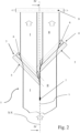
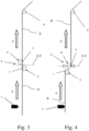
figure 1 depicts a schematic plan view of an apparatus for splitting and spreading a continuous web in a configuration in which said apparatus does not act on the continuous web to split and spread it; -
figure 2 depicts the apparatus offigure 1 in a configuration in which it acts on the continuous web, cause it to split and spread; -
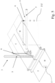
figure 3 depicts a sectional view according to the line of section III-III offigure 1 ; -
figure 4 depicts a sectional view according to the line of section IV-IV offigure 1 ; -
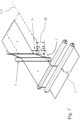
figures 5 and6 show a perspective view offigure 2 , in which the apparatus acts on the continuous web causing it to split and spread, according to two different points of view and -
figure 7 depicts an enlarged detail offigure 5 to better show the action of the accessory on one of the two parts in which the starting web is split. - With reference to the accompanying
figures, 1 globally denotes an apparatus according to the invention for splitting and spreading a portion of continuous web. - In particular, the apparatus 1 comprises:
- supporting and guiding means for defining a web path P extending along a predetermined longitudinal direction X-X between an input zone and an output zone, in which said web path P is designed to be travelled by a continuous stretched web running in a predetermined feed direction A from said input zone toward said output zone and
- cutting means 2 located in a predetermined transverse position of said web path P to determine a cutting line L extending along said longitudinal direction X-X in a continuous web running along said path P.
- A path section upstream of said
cutting means 2 and a path section downstream of saidcutting means 2 are defined in said web path P, said upstream and downstream sections being defined with reference to the feed direction A of a web along said web path. - The aforesaid cutting line L splits the aforesaid path section downstream of the cutting means 2 into two distinct longitudinal portions, in particular a first longitudinal portion I and a second longitudinal portion II.
- The aforesaid supporting and guiding means comprise two
respective pairs - a first pair of turning
bars 3 extending transversely to said first longitudinal portion I of the web path P and starting from said cutting line L and - a second pair of turning
bars 4 extending transversely to said second longitudinal portion II of the web path P and starting from said cutting line L, - The aforesaid two
respective pairs - It should be noted that the aforesaid first pair of turning
bars 3 and the aforesaid second pair of turningbars 4 are inclined with respect to the cutting line L so as to diverge from each other when running along the aforesaid feed direction A along the longitudinal direction X-X. - Each
respective pair first turning bar 5 and asecond turning bar 6 which are designed to contact, with arespective contact portion first turning bar 5 and thesecond turning bar 6 of eachpair - Advantageously:
- the
first turning bar 5 and thesecond turning bar 6 of eachrespective pair bar 5 being closer to the aforesaid cutting means 2 than thesecond turning bar 6 and - the
first turning bar 5 and thesecond turning bar 6 of eachrespective pair second turning bar 6 is moved past said first turningbar 5 to pass:- from a coplanar configuration in which said
contact portion 8 of saidsecond turning bar 6 is substantially coplanar with saidcontact portion 7 of said first turningbar 5 and said web path P passing between said first turningbar 5 and saidsecond turning bar 6 extends straight between thefirst turning bar 5 and thesecond turning bar 6 of eachrespective pair - an offset configuration in which said
contact portion 8 of saidsecond turning bar 6 extends in said orthogonal direction Z-Z beyond saidcontact portion 7 of said first turningbar 5 and said web path P has a section at the exit of eachrespective pair respective pair
- from a coplanar configuration in which said
- Preferably, in the aforesaid offset configuration in which the
contact portion 8 of thesecond turning bar 6, i.e., the one farthest back from thecutting means 2, extends in the orthogonal direction Z-Z beyond thecontact portion 7 of saidfirst turning bar 5, the web path P, when crossing each pair of turningbars - Preferably, in each
respective pair second turning bar 6, i.e., the one farthest back from thecutting means 2, is movable and adjustable in positioning in said orthogonal direction Z-Z with respect to said first turningbar 5 which is fixed in said orthogonal direction Z-Z. - Preferably, the apparatus 1 comprises actuating means for causing displacement/adjustment in said orthogonal direction Z-Z of the
second turning bar 6 with respect to the respectivefirst turning bar 5 of eachrespective pair - Preferably, the aforesaid first pair of turning
bars 3 and the aforesaid second pair of turningbars 4 are offset from each other in the longitudinal direction X-X to avoid any mutual interference thereof at said cutting line L, this allows, for example, to have an arrangement in which both thefirst turning bar 5 and thesecond turning bar 6 of each respective pair of turningbars figures 1 and2 ). - Preferably, the aforesaid turning bars have a low friction surface so as not to obstruct the sliding of a continuous web in contact therewith. For example, according to a non-exhaustive list, the aforesaid turning bars can be turning bars with air cushions, turning bars with a lapped surface and/or turning bars coated with low-adhesion material.
- Preferably, the aforesaid supporting and guiding means for defining a web path P further comprise at least one reversing roller 9:
- having a high-friction surface and
- located downstream of said
pairs cutting means 2 and running along the first longitudinal portion I and the second longitudinal portion II. - Such at least one reversing
roller 9 has the function of fixing the transverse displacement of the longitudinal portions of continuous web which are spread/moved apart as they move past saidrespective pairs - In addition to what has been described above, the apparatus 1 can comprise further turning bars known per se and arranged for guiding and supporting a continuous web or two continuous webs spread out along said web path P.
- With regard to the aforesaid cutting means 2, it should be noted that, in accordance with the illustrated embodiment, they are movable and adjustable to reversibly move:
- from a position away from said web path P, to avoid interference thereof with a continuous web running in said web path P (see
figures 1 and3 ) - to a working position in which they interfere with said web path P to form a longitudinal cut in a continuous web running along said web path P (see
Figures 2 ,4 ,5 ,6 and7 ). - Preferably, in accordance with the embodiment illustrated:
- the aforesaid turning bars extend along horizontal planes;
- in each
pair bar 5 and saidsecond turning bar 6 are designed to contact, by arespective contact portion - in said offset configuration, said
contact portion 8 of saidsecond turning bar 6 vertically extends upwards in said orthogonal direction Z-Z (by a distance "D" as shown infigure 7 ) beyond saidcontact portion 7 of said first turningbar 5, so that said web path P will have a section at the exit of eachrespective pair respective pair - According to the invention, the method for splitting and spreading a continuous web into two continuous longitudinal portions, comprises the steps of:
- arranging a web path P extending along a predetermined longitudinal direction X-X between an input zone and an output zone in which an extended continuous web will be supported and guided by supporting and guiding means;
- running a continuous web along said web path P with a feed direction A from an input zone to an output zone;
- arranging cutting means 2 located in a predetermined transverse position of said web path P to form a cutting line L extending along said longitudinal direction X-X;
- cutting said continuous web running in the feed direction along said path P by said cutting means 2 to split, downstream of said cutting means 2, said continuous web into a first longitudinal portion I and a second longitudinal portion II;
- arranging a first pair of turning
bars 3 and a second pair of turningbars 4 positioned:- downstream of said cutting means 2 with reference to the feed direction A of said web and
- extending transverse to said web path P at an angle α other than 90°, preferably at an angle α comprised between 25° and 65 from said cutting line L, so that said first pair of turning
bars 3 and said second pair of turningbars 4 will extend on opposite sides from said cutting line L, such that said first pair of turningbars 3 and said second pair of turningbars 4 will only be run along by said first longitudinal portion and, respectively, only by said second longitudinal portion II;
- in which each
respective pair first turning bar 5 and asecond turning bar 6 which are designed to contact, with arespective contact portion first turning bar 5 and thesecond turning bar 6 of eachpair - in which:
- the
first turning bar 5 and thesecond turning bar 6 of eachrespective pair bar 5 being closer to cutting means 2 with respect to said second turning bar; - the
first turning bar 5 and thesecond turning bar 6 of eachrespective pair contact portion 8 of saidsecond turning bar 6 extends beyond saidcontact portion 7 of said first turningbar 5 in said orthogonal direction Z-Z and said web path P has a section at the exit of eachrespective pair respective pair - said method comprises the step of causing said first longitudinal portion of the cut web to run along said
first pair 3 of turning bars and of causing said second longitudinal portion of said cut web to run along saidsecond pair 3 of turning bars, whereas thesecond turning bar 6 of eachrespective pair first turning bar 5,
- the
- so as to cause said web path P and said longitudinal portions of cut web to assume a pattern having a section at the exit of each
respective pair respective pair - Such a method therefore makes it possible to interrupt the longitudinal continuity of the initially continuous web, dividing it into two continuous webs of smaller width, the sum of the widths of the two continuous longitudinal webs of smaller width being equal to the transverse width of the starting web.
- When the
second turning bar 6 of eachpair first turning bar 5 closest to the cutting means in the aforesaid orthogonal direction Z-Z, an offset is obtained in the orthogonal direction Z-Z of the section of the two longitudinal webs in output from eachpair aforesaid pairs respective pair - Subsequently, the aforesaid transverse movement of the first longitudinal portion and the second longitudinal portion of the continuous webs away from each other and from said cutting line L is fixed by causing the two aforesaid longitudinal portions of the web to run on a reversing roller (9) having a high friction surface.
- Preferably, the aforesaid method is performed by means of an apparatus 1 as described above.
- As can be appreciated from what has been described, the apparatus according to the present invention for splitting and spreading a continuous web, as well as the method according to the present invention for splitting and spreading a continuous web, make it possible to meet the aforesaid needs and at the same time to overcome the drawbacks referred to in the introductory part of the present description with reference to the prior art. In fact, the aforesaid pairs of turning webs allow the two longitudinal portions cut from the starting continuous web to be moved away from each other without having to remove any portion of the initial continuous web.
- Advantageously, it is possible to adjust the distance between the two longitudinal portions cut from the starting continuous web by varying:
- the inclination with respect to the cutting line of the first turning bar and the second turning bar of each of the aforesaid pairs of turning bars and/or
- how much the second turning bar of each of the aforesaid pairs of turning bars exceeds beyond the first turning bar.
- Indicatively, for an inclination of the turning bars of about 45° with respect to the longitudinal cutting line L, the distance between the two longitudinal portions cut from the starting continuous web varies substantially proportionally to the increase of the offset of the second turning bar with respect to the first turning bar.
Claims (14)
- An apparatus (1) for splitting and spreading a continuous web, comprising:- supporting and guiding means for defining a web path (P) extending along a predetermined longitudinal axis (X-X) between an input zone and an output zone, wherein said web path (P) is designed to be traveled by a continuous web running in a predetermined feed direction (A) from said input zone toward said output zone and- cutting means (2) located in a predetermined transverse position of said web path (P) to form a cutting line (L) extending along said longitudinal axis (X-X) in a continuous web running along said path (P);wherein:- said web path (P) has a path section upstream of said cutting means (2) and a path section downstream of said cutting means (2), defined therein with reference to the feed direction (A) of a web along said web path;- said cutting line (L) splits said path section downstream of said cutting means (2) into two distinct longitudinal portions, namely a first longitudinal portion (I) and a second longitudinal portion (II);- said supporting and guiding means comprise two respective pairs (3, 4) of turning bars located at said path portion downstream of said cutting means (2);- a first pair of turning bars (3) extends transverse to said first longitudinal portion (I) of said web path (P) from said cutting line (L);- a second pair of turning bars (4) extends transverse to said second longitudinal portion (II) of said web path (P) from said cutting line (L), so that said first pair of turning bars (3) and said second pair of turning bars (4) extend on opposite sides from said cutting line (L);- said first pair of turning bars (3) and said second pair of turning bars (4) extend transverse to said cutting line (L) at an angle (α) other than 90°, preferably an angle (α) of 25° to 65;- said first pair of turning bars (3) and said second pair of turning bars (4) are inclined with respect to said cutting line (L) to diverge from each other when feeding along said longitudinal direction (X-X) in said feed direction (A) and- each respective pair (3,4) of turning bars comprises a first turning bar (5) and a second turning bar (6) which are designed to contact, by a respective contact portion (7,8), a first side and an opposite second side of a web running along said web path (P), so that said web path (P) will move between the first turning bar (5) and the second turning bar (6) of each pair (3, 4) of turning bars;characterized in that:- the first turning bar (5) and the second turning bar (6) of each respective pair (3,4) of turning bars are offset in said longitudinal direction (X-X) so that they will not overlap in an orthogonal direction (Z-Z) perpendicular to the plane that passes through said web path (P), said first turning bar (5) being closer to said cutting means (2) than said second turning bar (6) and- the first turning bar (5) and the second turning bar (6) of each respective pair (3,4) of turning bars are supported to be reversibly adjusted relative to each other in said orthogonal direction (Z-Z) until said second turning bar (6) is moved past said first turning bar (5) to move:• from a coplanar configuration in which said contact portion (8) of said second turning bar (6) is substantially coplanar with said contact portion (7) of said first turning bar (5) and said web path (P) passing between said first turning bar (5) and said second turning bar (6) extends straight between the first turning bar (5) and the second turning bar (6) of each respective pair (3, 4) to• an offset configuration in which said contact portion (8) of said second turning bar (6) extends in said orthogonal direction (Z-Z) beyond said contact portion (7) of said first turning bar (5) and said web path (P) has a section at the exit of each respective pair (3, 4) of turning bars offset in said orthogonal direction (Z-Z) from the section of said web path (P) at the entry of each respective pair (3, 4) of turning bars.
- An apparatus (1) as claimed in claim 1, wherein in said offset configuration in which said contact portion (8) of said second turning bar (6) extends in said orthogonal direction (Z-Z) beyond said contact portion (7) of said first turning bar (5), said web path (P), when moving past each pair (3,4) of turning bars follows a substantially "S-shaped" offset trajectory in said orthogonal direction (Z-Z).
- An apparatus (1) as claimed in claim 1 or 2, wherein, in each respective pair (3,4) of turning bars, said second turning bar (6) is movable and adjustable in its position in said orthogonal direction (Z-Z) with respect to said first turning bar (5) which is fixed in said orthogonal direction (Z-Z).
- An apparatus (1) as claimed in any of claims 1 to 3, comprising actuating means for causing displacement/adjustment in said orthogonal direction (Z-Z) of the second turning bar (6) with respect to the respective first turning bar (5) of each respective pair (3,4) of turning bars.
- An apparatus (1) as claimed in any of claims 1 to 4, wherein said first pair of turning bars (3) and said second pair of turning bars (4) are offset from each other in said longitudinal direction (X-X) to avoid any mutual interference thereof at said cutting line (L).
- An apparatus (1) as claimed in any of claims 1 to 5, wherein the first turning bar (5) and the second turning bar (6) of each respective pair (3,4) of turning bars extend beyond said cutting line (L) by a predetermined limited extent.
- An apparatus (1) as claimed in any of claims 1 to 6, wherein said turning bars have a low friction surface so that the sliding movement of a continuous web in contact therewith will not be inhibited, preferably said turning bars are turning bars with air cushions, turning bars with a lapped surface and/or turning bars coated with low-adhesion material.
- An apparatus (1) as claimed in any of claims 1 to 7, wherein said supporting and guiding means for defining a web path (P) comprise at least one idler roller (9):- having a high-friction surface and- located downstream of said pairs (3,4) of turning bars to contact an extended web running in said predetermined feed direction (A) along said web path (P),to fix the transverse displacement of longitudinal portions of the continuous web that are spread/moved apart as they move past said respective pairs (3,4) of turning bars in their offset configuration.
- An apparatus (1) as claimed in any of claims 1 to 8, comprising additional turning bars arranged to guide and support a continuous web or two continuous webs spread apart in said web path (P).
- An apparatus (1) as claimed in any of claims 1 to 9, wherein said cutting means (2) are movable and adjustable to reversibly move:- from a position away from said web path (P), to avoid interference thereof with a continuous running in said web path (P)- to a working position in which they interfere with said web path (P) to form a longitudinal cut in a continuous web running along said web path (P).
- An apparatus (1) as claimed in any of claims 1 to 10, wherein:
said turning bars extend along horizontal planes,- in each pair (3, 4) of turning bars, said first turning bar (5) and said second turning bar (6) are designed to contact, by a respective contact portion (7, 8), a top side and, on the other hand, an opposed top side of a web running along said web path (P) and- in said offset configuration, said contact portion (8) of said second turning bar (6) vertically extends upwards in said orthogonal direction (Z-Z) beyond said contact portion (7) of said first turning bar (5) so that said web path (P) will have a section at the exit of each respective pair (3, 4) of turning bars upwardly offset in said orthogonal direction (Z-Z) from the section of said web path (P) at the entry of each respective pair (3, 4) of turning bars. - A method of splitting and spreading a continuous web into two continuous longitudinal portions, comprising the steps of:- arranging a web path (P) extending along a predetermined longitudinal axis (X-X) between an input zone and an output zone in which an extended continuous web will be supported and guided by supporting and guiding means;- feeding a continuous web along said web path (P) in a feed direction (A) from an input zone to an output zone;- arranging cutting means (2) located in a predetermined transverse position of said web path (P) to form a cutting line (L) extending along said longitudinal axis (X-X);- cutting said continuous web running in the feed direction along said path (P) by said cutting means (2), to split said continuous web, downstream of said cutting means (2), into a first longitudinal portion and a second longitudinal portion;- arranging a first pair of turning bars (3) and a second pair of turning bars (4) so that they will be:• downstream of said cutting means (2) with reference to the feed direction (A) of said web and• extending transverse to said web path (P) at an angle (α) other than 90°, preferably an angle (α) of 25° to 65 from said cutting line (L), so that said first pair of turning bars (3) and said second pair of turning bars (4) will extend on opposite sides from said cutting line (L), such that said first pair of turning bars (3) and said second pair of turning bars (4) will be run along only by said first longitudinal portion and only by said second longitudinal portion respectively;wherein which each respective pair (3,4) of turning bars comprises a first turning bar (5) and a second turning bar (6) which are designed to contact, by a respective contact portion (7,8), a first side and an opposite second side of a web running along said web path (P), so that said web path (P) will move between the first turning bar (5) and the second turning bar (6) of each pair (3, 4) of turning bars;characterized in that:to cause said first longitudinal portion (I) and said second longitudinal portion (II) to move apart from each other and from said cutting line (L) as they run along the respective pair (3, 4) of turning bars.- the first turning bar (5) and the second turning bar (6) of each respective pair (3,4) of turning bars are offset in said longitudinal direction (X-X) so that they will not overlap in an orthogonal direction (Z-Z) perpendicular to the plane that passes through said web path (P), said first turning bar (5) being closer to said cutting means (2) than said second turning bar;- the first turning bar (5) and the second turning bar (6) of each respective pair (3, 4) of turning bars are designed to be offset in said orthogonal direction (Z-Z) to assume an offset configuration in which said contact portion (8) of said second turning bar (6) extends in said orthogonal direction (Z-Z) beyond said contact portion (7) of said first turning bar (5) and said web path (P) has a section at the exit of each respective pair (3, 4) of turning bars offset in said orthogonal direction (Z-Z) from the section of said web path (P) at the entry of each respective pair (3, 4) of turning bars, and- said method comprises the step of causing said first longitudinal portion of the cut web to run along said first pair (3) of turning bars and of causing said second longitudinal portion of said cut web to run along said second pair (3) of turning bars, whereas the second turning bar (6) of each respective pair (3,4) of turning bars is offset in said orthogonal direction (Z-Z) beyond said first turning bar (5) and of causing said web path (P) and said first longitudinal portion and said second longitudinal portion of the web to assume a pattern having a section at the exit of each respective pair (3, 4) of turning bars offset in said orthogonal direction (Z-Z) from the section of said first longitudinal portion and said second longitudinal portion of the web at the entry of each respective pair (3,4) of turning bars,
- A method of splitting and spreading a continuous web as claimed in claim 12, wherein said method is carried out by means of an apparatus (1) as claimed in any of claims 1 to 11.
- A method of splitting and spreading a continuous web as claimed in claim 12 or 13, wherein said transverse movement of the first longitudinal portion and of the second longitudinal portion of the continuous webs away from each other and from said cutting line (L) is fixed by causing said two longitudinal portions of the web to run on a reversing roller (9) having a high friction surface.
Applications Claiming Priority (2)
| Application Number | Priority Date | Filing Date | Title |
|---|---|---|---|
| IT102021000026405A IT202100026405A1 (en) | 2021-10-14 | 2021-10-14 | APPARATUS TO PERFORM THE DIVISION AND SPREADING OF A CONTINUOUS BELT |
| PCT/IB2022/059685 WO2023062503A1 (en) | 2021-10-14 | 2022-10-10 | Apparatus and method for splitting and spreading a continuous web |
Publications (3)
| Publication Number | Publication Date |
|---|---|
| EP4416093A1 EP4416093A1 (en) | 2024-08-21 |
| EP4416093B1 true EP4416093B1 (en) | 2025-03-05 |
| EP4416093C0 EP4416093C0 (en) | 2025-03-05 |
Family
ID=79601495
Family Applications (1)
| Application Number | Title | Priority Date | Filing Date |
|---|---|---|---|
| EP22801223.3A Active EP4416093B1 (en) | 2021-10-14 | 2022-10-10 | Apparatus and method for splitting and spreading a continuous web |
Country Status (3)
| Country | Link |
|---|---|
| EP (1) | EP4416093B1 (en) |
| IT (1) | IT202100026405A1 (en) |
| WO (1) | WO2023062503A1 (en) |
Families Citing this family (1)
| Publication number | Priority date | Publication date | Assignee | Title |
|---|---|---|---|---|
| CN221026762U (en) * | 2023-10-20 | 2024-05-28 | 三一技术装备有限公司 | Splitting machine |
Citations (4)
| Publication number | Priority date | Publication date | Assignee | Title |
|---|---|---|---|---|
| DE10023169A1 (en) | 2000-05-11 | 2001-11-15 | Roland Man Druckmasch | Dual action spreader for spreading strip material in rotation print machine with cutter has arrow-shaped turning bars either side of material, each with two connected rods in plane |
| DE10234674A1 (en) | 2002-07-30 | 2004-02-19 | Maschinenfabrik Wifag | Bahnspreizvorrichtung |
| DE10337248A1 (en) | 2003-08-13 | 2005-03-17 | Maschinenfabrik Wifag | Web spreading method and web spreading device |
| DE102008005395A1 (en) | 2008-01-21 | 2009-07-30 | Sew-Eurodrive Gmbh & Co. Kg | Apparatus and method for manufacturing a device |
Family Cites Families (4)
| Publication number | Priority date | Publication date | Assignee | Title |
|---|---|---|---|---|
| DE2007569B1 (en) * | 1970-02-19 | 1971-04-22 | Erwin Kampf Maschinenfabrik | Roller mill for pulling apart strips |
| DE3733129C2 (en) * | 1987-10-01 | 1999-02-18 | Focke & Co | Device for separating a material web into two partial webs |
| DE29509516U1 (en) * | 1995-06-14 | 1996-10-17 | Beloit Technologies, Inc., Wilmington, Del. | Separating device for winding devices for material webs that are longitudinally divided into several partial webs |
| DE102012009648A1 (en) * | 2012-05-14 | 2013-11-14 | Weber Maschinenbau Gmbh Breidenbach | spreading |
-
2021
- 2021-10-14 IT IT102021000026405A patent/IT202100026405A1/en unknown
-
2022
- 2022-10-10 EP EP22801223.3A patent/EP4416093B1/en active Active
- 2022-10-10 WO PCT/IB2022/059685 patent/WO2023062503A1/en not_active Ceased
Patent Citations (4)
| Publication number | Priority date | Publication date | Assignee | Title |
|---|---|---|---|---|
| DE10023169A1 (en) | 2000-05-11 | 2001-11-15 | Roland Man Druckmasch | Dual action spreader for spreading strip material in rotation print machine with cutter has arrow-shaped turning bars either side of material, each with two connected rods in plane |
| DE10234674A1 (en) | 2002-07-30 | 2004-02-19 | Maschinenfabrik Wifag | Bahnspreizvorrichtung |
| DE10337248A1 (en) | 2003-08-13 | 2005-03-17 | Maschinenfabrik Wifag | Web spreading method and web spreading device |
| DE102008005395A1 (en) | 2008-01-21 | 2009-07-30 | Sew-Eurodrive Gmbh & Co. Kg | Apparatus and method for manufacturing a device |
Non-Patent Citations (2)
| Title |
|---|
| "Der Rollen Offset Druck, 1. Auflage", 1 January 1995, FACH SCHRIFTEN VERLAG , Fellbach, ISBN: 978-3-931436-01-8, article WOLFGANG WALENSKI: "Der Falzaufbau", pages: 186 - 197, XP055434142 |
| "Technologie des Offsetdrucks", 1 January 1989, VEB FACHBUCHVERLAG LEIPZIG, Leipzig, ISBN: 3-343-00527-4, article RUDI RIEDL; DIETER NEUMANN; JÜRGEN TEUBNER: "8.1.2 Bahnführung", pages: 202 - 216, XP009564441 |
Also Published As
| Publication number | Publication date |
|---|---|
| EP4416093A1 (en) | 2024-08-21 |
| IT202100026405A1 (en) | 2023-04-14 |
| EP4416093C0 (en) | 2025-03-05 |
| WO2023062503A1 (en) | 2023-04-20 |
Similar Documents
| Publication | Publication Date | Title |
|---|---|---|
| KR0134890B1 (en) | Rool cutting machine | |
| CN107285089B (en) | Web material splicing apparatus, unreel device and operating method comprising the splicing apparatus | |
| US5782426A (en) | Method and device for reeling a paper or board web | |
| JP3516842B2 (en) | Winding apparatus, particularly a method for passing a paper web or equivalent web-like material in a slitter winder, and apparatus for performing the method | |
| US6185971B1 (en) | Hot rolled material take-up equipment and take-up method | |
| US5405099A (en) | Web-slitting apparatus with driven pinch and windup rollers for varying web tension | |
| US4502675A (en) | Longitudinal folding of webs, folding board system therefor | |
| US9260266B2 (en) | Method for separating partial webs in a slitter winder | |
| EP4416093B1 (en) | Apparatus and method for splitting and spreading a continuous web | |
| US5782425A (en) | Method and device for winding a paper web | |
| US6467720B1 (en) | Process for winding a material web and winding machine for performing the process | |
| US5158648A (en) | Apparatus for forming a movable threading tail | |
| FI121305B (en) | A method for operating a winder and an adhesive application apparatus | |
| US5234549A (en) | Apparatus for forming a movable threading tail | |
| US6338451B1 (en) | Cross cutting device for a winding machine | |
| US6016989A (en) | Paper web autosplicer | |
| JP3462369B2 (en) | Paper web winding method and winding apparatus | |
| US6869039B2 (en) | Method and apparatus for winding a paper web | |
| US1355107A (en) | Winding mechanism | |
| EP0505712A1 (en) | Surface winder and method | |
| US7237743B2 (en) | Sheet windup starter | |
| JP3033627B2 (en) | Metal strip slitting equipment | |
| CN118992647A (en) | Method for applying adhesive in slitter-winder and slitter-winder comprising a system for applying adhesive | |
| JP2001293683A (en) | Lengthy material cutting device | |
| DE19848812A1 (en) | Device to place front end of paper length on reel-spool has placing unit to press paper length to surface of placing roller in front of winding gap |
Legal Events
| Date | Code | Title | Description |
|---|---|---|---|
| STAA | Information on the status of an ep patent application or granted ep patent |
Free format text: STATUS: UNKNOWN |
|
| STAA | Information on the status of an ep patent application or granted ep patent |
Free format text: STATUS: THE INTERNATIONAL PUBLICATION HAS BEEN MADE |
|
| PUAI | Public reference made under article 153(3) epc to a published international application that has entered the european phase |
Free format text: ORIGINAL CODE: 0009012 |
|
| STAA | Information on the status of an ep patent application or granted ep patent |
Free format text: STATUS: REQUEST FOR EXAMINATION WAS MADE |
|
| 17P | Request for examination filed |
Effective date: 20240318 |
|
| AK | Designated contracting states |
Kind code of ref document: A1 Designated state(s): AL AT BE BG CH CY CZ DE DK EE ES FI FR GB GR HR HU IE IS IT LI LT LU LV MC ME MK MT NL NO PL PT RO RS SE SI SK SM TR |
|
| GRAP | Despatch of communication of intention to grant a patent |
Free format text: ORIGINAL CODE: EPIDOSNIGR1 |
|
| STAA | Information on the status of an ep patent application or granted ep patent |
Free format text: STATUS: GRANT OF PATENT IS INTENDED |
|
| DAV | Request for validation of the european patent (deleted) | ||
| DAX | Request for extension of the european patent (deleted) | ||
| INTG | Intention to grant announced |
Effective date: 20241209 |
|
| GRAS | Grant fee paid |
Free format text: ORIGINAL CODE: EPIDOSNIGR3 |
|
| GRAA | (expected) grant |
Free format text: ORIGINAL CODE: 0009210 |
|
| STAA | Information on the status of an ep patent application or granted ep patent |
Free format text: STATUS: THE PATENT HAS BEEN GRANTED |
|
| AK | Designated contracting states |
Kind code of ref document: B1 Designated state(s): AL AT BE BG CH CY CZ DE DK EE ES FI FR GB GR HR HU IE IS IT LI LT LU LV MC ME MK MT NL NO PL PT RO RS SE SI SK SM TR |
|
| REG | Reference to a national code |
Ref country code: GB Ref legal event code: FG4D |
|
| REG | Reference to a national code |
Ref country code: CH Ref legal event code: EP |
|
| REG | Reference to a national code |
Ref country code: DE Ref legal event code: R096 Ref document number: 602022011526 Country of ref document: DE |
|
| REG | Reference to a national code |
Ref country code: IE Ref legal event code: FG4D |
|
| U01 | Request for unitary effect filed |
Effective date: 20250328 |
|
| U07 | Unitary effect registered |
Designated state(s): AT BE BG DE DK EE FI FR IT LT LU LV MT NL PT RO SE SI Effective date: 20250403 |
|
| PG25 | Lapsed in a contracting state [announced via postgrant information from national office to epo] |
Ref country code: RS Free format text: LAPSE BECAUSE OF FAILURE TO SUBMIT A TRANSLATION OF THE DESCRIPTION OR TO PAY THE FEE WITHIN THE PRESCRIBED TIME-LIMIT Effective date: 20250605 |
|
| PG25 | Lapsed in a contracting state [announced via postgrant information from national office to epo] |
Ref country code: ES Free format text: LAPSE BECAUSE OF FAILURE TO SUBMIT A TRANSLATION OF THE DESCRIPTION OR TO PAY THE FEE WITHIN THE PRESCRIBED TIME-LIMIT Effective date: 20250305 |
|
| PG25 | Lapsed in a contracting state [announced via postgrant information from national office to epo] |
Ref country code: NO Free format text: LAPSE BECAUSE OF FAILURE TO SUBMIT A TRANSLATION OF THE DESCRIPTION OR TO PAY THE FEE WITHIN THE PRESCRIBED TIME-LIMIT Effective date: 20250605 |
|
| PG25 | Lapsed in a contracting state [announced via postgrant information from national office to epo] |
Ref country code: HR Free format text: LAPSE BECAUSE OF FAILURE TO SUBMIT A TRANSLATION OF THE DESCRIPTION OR TO PAY THE FEE WITHIN THE PRESCRIBED TIME-LIMIT Effective date: 20250305 |
|
| PG25 | Lapsed in a contracting state [announced via postgrant information from national office to epo] |
Ref country code: GR Free format text: LAPSE BECAUSE OF FAILURE TO SUBMIT A TRANSLATION OF THE DESCRIPTION OR TO PAY THE FEE WITHIN THE PRESCRIBED TIME-LIMIT Effective date: 20250606 |
|
| PG25 | Lapsed in a contracting state [announced via postgrant information from national office to epo] |
Ref country code: SM Free format text: LAPSE BECAUSE OF FAILURE TO SUBMIT A TRANSLATION OF THE DESCRIPTION OR TO PAY THE FEE WITHIN THE PRESCRIBED TIME-LIMIT Effective date: 20250305 |
|
| PG25 | Lapsed in a contracting state [announced via postgrant information from national office to epo] |
Ref country code: PL Free format text: LAPSE BECAUSE OF FAILURE TO SUBMIT A TRANSLATION OF THE DESCRIPTION OR TO PAY THE FEE WITHIN THE PRESCRIBED TIME-LIMIT Effective date: 20250305 |
|
| PG25 | Lapsed in a contracting state [announced via postgrant information from national office to epo] |
Ref country code: CZ Free format text: LAPSE BECAUSE OF FAILURE TO SUBMIT A TRANSLATION OF THE DESCRIPTION OR TO PAY THE FEE WITHIN THE PRESCRIBED TIME-LIMIT Effective date: 20250305 |
|
| PG25 | Lapsed in a contracting state [announced via postgrant information from national office to epo] |
Ref country code: SK Free format text: LAPSE BECAUSE OF FAILURE TO SUBMIT A TRANSLATION OF THE DESCRIPTION OR TO PAY THE FEE WITHIN THE PRESCRIBED TIME-LIMIT Effective date: 20250305 |
|
| PG25 | Lapsed in a contracting state [announced via postgrant information from national office to epo] |
Ref country code: IS Free format text: LAPSE BECAUSE OF FAILURE TO SUBMIT A TRANSLATION OF THE DESCRIPTION OR TO PAY THE FEE WITHIN THE PRESCRIBED TIME-LIMIT Effective date: 20250705 |
|
| U20 | Renewal fee for the european patent with unitary effect paid |
Year of fee payment: 4 Effective date: 20251028 |
|
| PLBI | Opposition filed |
Free format text: ORIGINAL CODE: 0009260 |
|
| PLAX | Notice of opposition and request to file observation + time limit sent |
Free format text: ORIGINAL CODE: EPIDOSNOBS2 |
|
| 26 | Opposition filed |
Opponent name: MANROLAND GOSS WEB SYSTEMS GMBH Effective date: 20251204 |