EP4416032B1 - Architektur für eine datenübertragung zwischen mehreren elektrischen triebfahrzeugen und einer zugehörigen fernsteuerungszentrale - Google Patents
Architektur für eine datenübertragung zwischen mehreren elektrischen triebfahrzeugen und einer zugehörigen fernsteuerungszentrale Download PDFInfo
- Publication number
- EP4416032B1 EP4416032B1 EP23820828.4A EP23820828A EP4416032B1 EP 4416032 B1 EP4416032 B1 EP 4416032B1 EP 23820828 A EP23820828 A EP 23820828A EP 4416032 B1 EP4416032 B1 EP 4416032B1
- Authority
- EP
- European Patent Office
- Prior art keywords
- type
- data transmission
- grounded
- architecture
- signal
- Prior art date
- Legal status (The legal status is an assumption and is not a legal conclusion. Google has not performed a legal analysis and makes no representation as to the accuracy of the status listed.)
- Active
Links
Images


Classifications
-
- B—PERFORMING OPERATIONS; TRANSPORTING
- B61—RAILWAYS
- B61L—GUIDING RAILWAY TRAFFIC; ENSURING THE SAFETY OF RAILWAY TRAFFIC
- B61L15/00—Indicators provided on the vehicle or train for signalling purposes
- B61L15/0018—Communication with or on the vehicle or train
Definitions
- the present invention refers to an architecture for a data transmission between a plurality of vehicles and a remote control center of a transport network.
- the invention refers in particular, but not in an exclusive way, to an architecture for a data transmission for the communication in a mass transport network, such as the railway or underground network and the following description is made with reference to this field of application with the sole purpose of simplifying the exposition thereof.
- an electric traction mass transport system comprises a plurality of vehicles adapted to accommodate a plurality of passengers, or vehicles, moved on suitable tracks and an electric power supply line which is able to supply power to said vehicles; said system being also indicated as transport network.
- pantograph defines a device which takes electric current from an overhead contact line, generally placed on the roof of a vehicle such as a railway or tramway vehicle.
- third rail power supply wherein an added rail is placed in between or beside the two tracks or rails on which the vehicle transits, such as a train or an underground carriage, the electrical contact being ensured by a shoe which slides or a lateral wheel which rotates thereon, suitable isolating coverings being provided for protecting possible workers on the tracks.
- One of the problems which should be dealt with in managing a transport network of the indicated above type is the data transmission, in particular between single transport means which circulate in the network and a control center thereof.
- Said data transmission is usually assigned to designated data networks, comprising transmissive supports with optical fiber and copper cable which are inserted in system infrastructures along the transport network, used in particular for transmitting data related to the circulating vehicles in addition to company communications of the administrative and management type.
- designated data networks comprising transmissive supports with optical fiber and copper cable which are inserted in system infrastructures along the transport network, used in particular for transmitting data related to the circulating vehicles in addition to company communications of the administrative and management type.
- the railway data network covers more than 12,000 Km of railway lines and constitutes the fundamental support for all the railway transmission systems.
- GSM-R Global System for Mobile communications
- the fixed telephony lines are used in managing the transport lines.
- the fixed telephony system is used by the circulation and maintenance operators for the communications related to the railway operativity.
- designated telephone stations are present on the desks of the circulation operators, such as station masters (DM from Italian: “dirigenti movimento"), train dispatchers (DC from Italian: “dirigenti centrali”) and operational train dispatchers (DCO from Italian: "dirigenti centrali operativi”), in the electric traction (ET) desks, such as cabs, electric substations (ESS), DOTE central desks, in the station yards and along the lines, outdoors or in a gallery.
- DM from Italian: "dirigenti movimento”
- train dispatchers DC from Italian: “dirigenti centrali”
- DCO operational train dispatchers
- DOTE central desks in the electric traction (ET) desks, such as cabs, electric substations (ESS), DOTE central desks, in the station yards and along the lines
- a communication system for a consist such as for example a train, is described in patent No. US 8,825,239 B2 issued on September 2nd, 2014 in the name of General Electric Company, said system being not anyway able to allow a continuous data transmission when the consist is moving.
- wired data transmission modes are generally used especially for the stations, and wireless ones in particular for the communication between moving vehicles and a corresponding remote control center.
- the technical problem of the present invention is to provide an architecture for the continuous data transmission in a transport network comprising a plurality of vehicles moving on tracks to which power is supplied by a low/medium voltage power supply line and which are in communication with a remote control center, having structural and functional characteristics so as to guarantee a transmission which is always reliable, without interruptions and with low additional costs, overcoming the limits and drawbacks which are still affecting the solutions made according to the prior art.
- the solution idea underlying the present invention is to modify the BPLC communication mode (Broadband over Power Lines Communication) to allow the continuous data transmission between vehicles moving in a transport network and a remote control center using the low/medium voltage power supply line of the same vehicles, the term low/medium voltage meaning a voltage value lower than 30 kV.
- BPLC communication mode Broadband over Power Lines Communication
- the invention comprises the following additional and optional features, taken singularly or, if necessary, in combination.
- the onboard device can be connected to the grounded device based on a signal/noise ratio adapted to guarantee a bidirectional communication with the ethernet backbone network.
- the onboard device can be connected to the grounded device based on additional link quality parameters, chosen among an authentication status of master and/or slave PLC modules, RSSI (Received Signal Strength Indication) of a beacon frame between a master PLC module and a slave PLC module, an AGC (Automatic Gain Control) on a RxPGA (Receiver's Programmable Gain Amplifier), being used to compensate an amplitude of a signal received from the receiver, and a physical data rate based on the data dynamically exchanged on an estimated channel between a master PLC module and a slave PLC module.
- RSSI Receiveived Signal Strength Indication
- AGC Automatic Gain Control
- RxPGA Receiver's Programmable Gain Amplifier
- the adapter includes at least one first PLC module of a first type and a second PLC module of a second type connected to a management module with gateway function, said adapter being adapted to convert digital data in an analog radiofrequency signal and being connected to a low/medium voltage local power supply line of the vehicle and to the grounded device when connected to said onboard device.
- the onboard device of each vehicle can further comprise a decoupler adapted to eliminate a continuous component of a power supply voltage on the local power supply line and to realise a high-pass filter to eliminate low-frequency noise in an input signal and obtain an information signal to be transmitted to the grounded device when connected to the onboard device, enabling a connection with the power supply network and a data transmission according to the BPLC communication mode towards the backbone ethernet network.
- a decoupler adapted to eliminate a continuous component of a power supply voltage on the local power supply line and to realise a high-pass filter to eliminate low-frequency noise in an input signal and obtain an information signal to be transmitted to the grounded device when connected to the onboard device, enabling a connection with the power supply network and a data transmission according to the BPLC communication mode towards the backbone ethernet network.
- the decoupler can be a passive component and the adapter can be an active component.
- the onboard device can be connected to a local network of the vehicles.
- the architecture for a data transmission can comprise a plurality of grounded devices of a first type and a plurality of grounded devices of a second type which are alternating and spaced with respect to each other according to a distance.
- each of the grounded devices of the first type can comprise at least one adapter, in turn including a PLC module of the first type and a corresponding management module which is able to connect to the first PLC module of the first type of the adapter of the onboard device and each of the grounded devices of the second type can comprise at least one adapter, in turn including a PLC module of the second type and a corresponding management module which is able to connect to the second PLC module of the second type of the adapter of the onboard device.
- the grounded devices of the first type and of the second type can respectively comprise a management module connected to the PLC modules of the first type and of the second type.
- each of the grounded devices can comprise a decoupler adapted to eliminate a continuous component from a power supply voltage and realise a high-pass filter to eliminate a low frequency noise in an input signal and obtain an information signal to be transmitted to the onboard device.
- each of the grounded devices can further comprise a connector block and grounding devices.
- the decoupler can be a passive component and the adapter can be an active component.
- the substations can be chosen among the railway or tramway stations, railway or tramway stops, electrical substations of railway or tramway networks, additional structures positioned along railway or tramway lines.
- the vehicles can be chosen among trains, trolleybus, trams and other electric traction transport means.
- the grounded devices can be placed at a distance comprised between 1m and 1500m from the onboard devices of the vehicles.
- the architecture for a data transmission can carry out a data handover from a grounded device to a following one by verification of a minimum value of signal/noise ratio transmitted between the grounded device and the onboard device.
- the architecture for data transmission can transmit:
- the technical problem is also solved by a method for the continuous data transmission in an architecture made as indicated above, wherein the grounded devices are divided and alternating with respect to each other between a first type and a second type, each device type being adapted to be connected to a distinct module of the onboard device, the method comprising the steps of:
- additional link quality parameters can be used to evaluate the grounded device to be connected to one of the modules of the onboard device.
- the additional link quality parameters can be chosen among an authentication status of master and/or slave PLC modules, RSSI (Received Signal Strength Indication) of a beacon frame between a master PLC module and a slave PLC module, an AGC (Automatic Gain Control) on a RxPGA (Receiver's Programmable Gain Amplifier), being used to compensate an amplitude of a signal received from the receiver, and a physical data rate based on the data dynamically exchanged on an estimated channel between a master PLC module and a slave PLC module.
- RSSI Receiveived Signal Strength Indication
- AGC Automatic Gain Control
- RxPGA Receiver's Programmable Gain Amplifier
- handover rules can be used to drive the handover mechanism, chosen among a time of evaluation of the link quality parameters; a time between two scans, being a frequency of information retrieved from slave modules of grounded devices and roaming estimation; a no-return delay, being a minimum delay before returning to an already used master module; and a smoothing factor, being a weighing importance of latest signals vs older ones.
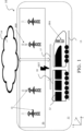
- an architecture for a data transmission made according to the present invention is generally and schematically indicated with 10.
- the architecture for a data transmission 10 is particularly adapted to connect a plurality of vehicles 12 moving in a transport network 11, for example along the tracks 13, with a network 14 of the so-called backbone or grounded type, that is a network interconnecting with other LAN subnetworks for exchanging information between said LAN subnetworks, in particular an ethernet network, the transport network 11 comprising a plurality of substations 15 connecting with a low/medium voltage power supply network 16 used to provide electric traction energy EET to the vehicles 12 and to local power supply lines 17 connected to the vehicles 12, for example in the form of overhead power supply lines, each vehicle 12 being provided with a pantograph 18 for the connection with said local power supply lines 17.
- the low/medium voltage power supply network 16 being adapted to provide the electric traction energy to the vehicles 12 by said third rail, supplementary to the tracks 13, the third rail being therefore essentially a local power supply line. It is pointed out that the term low/medium voltage means a voltage value lower than 30 kV.
- the power supply network 16 is also used for the continuous data transmission between the vehicles 12 and the ethernet backbone network 14, in particular using the BPLC communication mode (Broadband over Power Lines Communication).
- BPLC communication mode Broadband over Power Lines Communication
- the present invention in fact starts from the consideration that said electric line broadband BPLC communication mode allows the digital data transmission at relatively high speed, using the public cabled network for electric energy distribution.
- said BPLC communication mode allows the digital data transmission at relatively high speed, using the public cabled network for electric energy distribution.
- the following critical aspects have been advantageously faced and overcome:
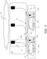
- the architecture for a data transmission 10 was advantageously provided with a transmission and decoupling system 20 inserted between the vehicles 12 moving in the transport network 11 and the substations 15 connecting with the power supply network 16 and particularly comprising:
- the architecture for a data transmission 10 comprises the ethernet backbone network 14 which is in bidirectional communication with the transmission and decoupling systems 20 of the vehicles 12 and allows the continuous bidirectional data transmission between said vehicles 12 and the ethernet backbone network 14.
- the onboard device 20A of each vehicle 12 comprises a decoupler 22A, which is a passive component connected to a local network 21 and to the grounded device 20B of the substations 15, via the local power supply line 17 which provides the electric traction energy EET to the same vehicle and is connected to the power supply network 16.
- a decoupler 22A which is a passive component connected to a local network 21 and to the grounded device 20B of the substations 15, via the local power supply line 17 which provides the electric traction energy EET to the same vehicle and is connected to the power supply network 16.
- the substations 15 where the grounded device 20B is to be installed can be chosen for example among the railway or tramway stations, railway or tramway stops, electrical railway or tramway substations or other structures positioned along the railway or tramway line.
- the onboard device 20A for example on trains, trolleybus, trams and other similar transport means.
- the onboard device 20A comprises the decoupler 22A to enable the connection with a low/medium voltage power supply line such as the local power supply line 17 of the vehicles 12 and the data transmission according to the BPLC communication mode by the power supply network 16.
- a low/medium voltage power supply line such as the local power supply line 17 of the vehicles 12
- the data transmission according to the BPLC communication mode by the power supply network 16.
- the onboard device 20A furthermore comprises an adapter 23A, which is an active component for the conversion of digital data in an analog radiofrequency signal to be sent to the decoupler 22A and, via the grounded device 20B, to the ethernet backbone network 14.
- an adapter 23A which is an active component for the conversion of digital data in an analog radiofrequency signal to be sent to the decoupler 22A and, via the grounded device 20B, to the ethernet backbone network 14.
- the decoupler 22A eliminates the continuous component of the power supply voltage on the local power supply line 17 and allows it to be connected with the adapter 23A.
- the passive component that is the decoupler 22A outside the vehicle 12, for example on the roof of the vehicle if power is supplied by pantograph or under its fairing in case of third rail power supply
- the active component that is the adapter 23A is usually housed inside the same vehicle, for example inside a carriage.
- the grounded device 20B comprises a decoupler 22B (passive component), also used to eliminate the continuous component from a power supply voltage and an adapter 23B (active component) for the conversion of digital data in an analog radiofrequency signal to be sent to the ethernet backbone network 14.
- a decoupler 22B passive component
- an adapter 23B active component
- the onboard device 20A comprises the decoupler 22A (passive component) and the adapter 23A (active component) and, analogously, the grounded device 20B comprises the decoupler 22B (passive component) and the adapter 23B (active component).
- the grounded device 20B can also comprise a junction box 24 of the power supply along a track 13 and possible other grounding devices (not shown).
- the decouplers 22A and 22B of the onboard device 20A and of the grounded device 20B, respectively, can be made equal to each other.
- the adapter 23B of the grounded device 20B connected in a bidirectional manner to the ethernet backbone network 14 and to the decoupler 22B, comprises at least one PLC module 25B and a management module 26B of said PLC module 25B, said management module 26B essentially acting as a gateway.
- the adapter 23B is a PLC master device being directly connected to the ethernet backbone network 14 and thus to one or more remote control center(s) connected thereto.
- the decoupler 22B comprises a pair of input terminals P1 which receive an input signal or native signal, being affected by noise, in particular low frequency interferences, and is configured so as to decouple the continuous traction voltage and provide a high-pass filter which is also able to eliminate the noise at low frequencies and obtain an information signal, which is correct and usable for the transmission towards the onboard device 20A, on a pair of output terminals P2.
- the architecture for a data transmission 10 comprises a plurality of grounded devices 20B including the adapter 23B with its PLC module 25B and its management module 26B and the decoupler 22B.
- the decoupler 22A of the onboard device 20A has a structure corresponding to the one of the decoupler 22B of the grounded device 20B and carries out an analogous high-pass filtering operation on the received signals.
- the decouplers 22A and 22B of the onboard device 20A and of the grounded device 20B use an operating band between 2MHz and 50MHz, more preferably between 12MHz and 30MHz, in order to avoid noises and interferences indicated above.
- the adapter 23A of the onboard device 20A instead comprises at least one pair of PLC modules 25A1, 25A2 of different type connected to a management module 26A acting as a gateway.
- the PLC modules 25A1, 25A2 are adapted to send diagnostic data of the onboard device 20A, in particular in terms of connection quality, to the management module 26A which, as will be clarified in the following, allows to carry out the so-called handover, that is the passage from a grounded device 20B to another one during the movement of the related vehicle 12, independently from a travel direction of said vehicle.
- the PLC modules 25A1, 25A2 of the adapter 23A of the onboard device 20A are configured as PLC slave devices.
- the communication between the onboard device 20A and a grounded device 20B is guaranteed for a distance comprised between 1m and 1500m.
- a suitable number of grounded devices 20B is thus provided along the transport network 11 in order to guarantee a safe and constant transmission.
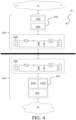
- the operating mode of the transmission and decoupling system 20 with the handover between a grounded device and another one while a vehicle 12 is moving is schematically illustrated in Figure 5 .
- each onboard device 20A comprises a pair of PLC modules 25A1, 25A2 connected to a management module 26A.
- the PLC modules of the grounded devices 20B are divided into a first type, indicated as Type 1, and a second type, indicated as Type 2 and are alternating with each other.
- the onboard device 20A comprises a first PLC module of the first type and a second PLC module of the second type.
- the transmission and decoupling system 20 comprises a first grounded device of the first type, indicated as Type 1-DT1-20B, a second grounded device of the second type, indicated as Type 2-DT2-20B, a third grounded device of the first type, indicated as Type 1-DT3-20B and a fourth grounded device of the second type, indicated as Type 2-DT4-20B.
- the onboard device 20A analogously comprises a decoupler 22A and an adapter 23A, in turn including a first PLC module of the first type Type 1-25A and a second PLC module of the second type Type 2-25B as well as a management module 26A.
- the first PLC module of the first type Type 1-25A of the onboard device 20A can only communicate with modules of the first type of the grounded devices 20B, in the example the PLC module of the first type Type 1-DT1-25B of the first grounded device Type 1-DT1-20B and the PLC module of the first type Type 1-DT3-25B of the third grounded device Type 1-DT3-20B and the second PLC module of the second type Type 2-25A of the onboard device 20A can only communicate with modules of the second type of the grounded devices 20B, in the example the PLC module of the second type Type 2-DT2-25B of the second grounded device Type 2-DT2-20B and the PLC module of the second type Type 2-DT4-25B of the fourth grounded device Type 2-DT4-20B.
- the grounded devices 20B are placed at intervals with respect to each other according to the distances L1, L2, L3, preferably equal to each other.
- said distances are decided based on a minimum signal/noise ratio necessary used as link quality parameter for obtaining a throughput required by the particular application which uses this type of communication, such as for example voice, data, etc. and are according to the type of power supply network of the architecture for a data transmission 10, such as for example overhead railway or tramway contact line, or third rail power supply, to name a few.
- the maximum distance between the two grounded devices 20B is approximately equal to 700m.
- the grounded devices 20B including adapters 23B being PLC master devices with master PLC modules 25B of different types, alternate one another, so forming a PLC Network on the overhead railway or tramway contact line.
- the first PLC module of the first type Type 1-25A1 of the onboard device 20A is only connected to the PLC module of the first type Type 1-DT1-25B of the first grounded device Type 1-DT 1-20B communicating a signal DT1-S11, which has a signal/noise ratio which is enough to guarantee a bidirectional data exchange between onboard device 20A and first grounded device Type 1-DT1-20B.
- the communication occurs between the first PLC module of the first type Type 1-25A1 of the onboard device 20A and the PLC module of the first type Type 1-DT1-25B connected to the decoupler 22B of the first grounded device Type 1-DT 1-20B.
- the first PLC module of the first type Type 1-25A1 of the onboard device 20A continues to communicate a signal DT1-S21 with the PLC module of the first type Type1-DT1-25B of the first grounded device Type 1-DT 1-20B.
- the second PLC module of the second type Type 2-25A2 of the onboard device 20A is associated, that is it communicates a signal DT2-S22 to the PLC module of the second type Type 2-DT2-25B of the second grounded device Type 2-DT2-20B.
- the bidirectional data transmission only occurs between the first PLC module of the first type Type 1-25A1 of the onboard device 20A and the PLC module of the first type Type 1-DT1-25B of the first grounded device Type 1-DT1-20B, since only the first signal DT1-S21 has a signal/noise ratio which is enough to guarantee the connection with the onboard device 20A and the correct bidirectional data transmission towards the ethernet backbone network 14.
- the first PLC module of the first type Type 1-25A1 of the onboard device 20A is able to communicate a signal DT1-S31 to the PLC module of the first type Type1-DT1-25B of the first grounded device Type 1-DT 1-20B.
- the second PLC module of the second type Type 2-25A2 of the onboard device 20A is able to send a second signal DT2-S32 to the PLC module of the second type Type 2-DT2-25B of the second grounded device Type 2-DT2-20B.
- the bidirectional data transmission occurs in that case between the second PLC module of the second type Type 2-25A2 of the onboard device 20A and the PLC module of the second type Type 2-DT2-25B of the second grounded device Type 2-DT2-20B, since the signal DT2-S32 has a signal/noise ratio which is enough to guarantee the bidirectional data transmission with onboard device 20A and is higher than the signal/noise ratio of the signal DT1-S31.
- the handover is carried out between the first grounded device Type 1-DT1-20B and the second grounded device Type 2-DT2-20B.
- the second PLC module of the second type Type 2-25A2 of the onboard device 20A is only connected to the PLC module of the second type Type 2-DT2-25B of the second grounded device Type 2-DT1-20B, by a signal DT2-S42, which has a signal/noise ratio which is enough to guarantee a bidirectional data exchange with the ethernet backbone network 14.
- slave PLC modules 25A1, 25A2 of the adapters 23A of the onboard devices 20A are able to connect directly to the master PLC modules 25B of the adapters 23B of the grounded devices 20B, according to the alternation of their types, without needing repeaters of any kind to be provided.
- the onboard device 20A verifies the connection signals between the reachable grounded devices 20B at any time and chooses the one with a signal/noise ratio adequate to the data transmission.
- the architecture for a data transmission 10 guarantees a constant and safe transmission between vehicles 12 and ethernet backbone network 14 and can be therefore used for transmitting any type of data and in particular:
- the PLC modules of the adapters 23A, 23B are able to exchange diagnostic data tied to the connection quality with the management modules 26A, 26B so as to allow the handover between grounded devices 20B, in particular between one master PLC module 25B to another one, in particular using as link quality parameter the signal/noise ratio, as above explained.
- the handover mechanism can be also tied to the additional link quality parameters, being provided to the management modules 26A, 26B.
- the connection between onboard devices and grounded devices can be also based on:
- handover rules can be used to drive the handover mechanism and in particular:
- the handover mechanism at the grounded devices 20B of the proposed architecture is a level 2 switchover mechanism wherein two master modules are simultaneously connected to two on board PLC modules and the active communication channel is switched between the on board PLC modules at the level 2 of the ISO/OSI stack.
- the architecture for a data transmission allows to use the electric power supply line which transmits the electric traction energy to the vehicles circulating in a transport network in order to establish a bidirectional connection between vehicles and remote control center, thanks to the use of the BPLC communication mode (Broadband over Power Lines Communication).
- BPLC communication mode Broadband over Power Lines Communication
- the architecture for a data transmission according to the present invention has low installations costs, since it does not need additional antennas, and low maintenance costs thanks to the use of components (decouplers, adapters) with a high average breaking time.
- the energy saving which the architecture for a data transmission according to the present invention allows to obtain is extremely significant. Taking into account, by way of example, only one underground line of 20 Km consisting of 20 stations and 22 trains, the energy consumption of the currently implemented solutions, which require transmission boxes with antennas each 400m and use Wi-Fi radio transmissions onboard the train, is equal to 21.19 KW, while the architecture for a data transmission with the BPLC communication mode, having grounded devices installed each 700m and onboard radio transmissions, has a consumption equal to 1.15KW, that is an energy saving equal to 94.5%.
- the architecture for a data transmission as proposed has a high scalability, since it can be expanded according to the needs of the transport network infrastructure, which can thus grow proportionally to the size and the coverage needs.
Landscapes
- Engineering & Computer Science (AREA)
- Mechanical Engineering (AREA)
- Cable Transmission Systems, Equalization Of Radio And Reduction Of Echo (AREA)
- Electric Propulsion And Braking For Vehicles (AREA)
- Train Traffic Observation, Control, And Security (AREA)
Claims (20)
- Architektur für eine Datenübertragung (10) zwischen einer Vielzahl von elektrischen Triebfahrzeugen (12), die sich in einem Verkehrsnetz (11) bewegen, und einem Backbone-Ethernet-Netzwerk (14), wobei das Verkehrsnetz (11) eine Vielzahl von Unterstationen (15), die mit einem Nieder-/Mittelspannungsversorgungsnetz (16) für die Fahrzeuge (12) verbunden sind, umfasst, dadurch gekennzeichnet, dass das Spannungsversorgungsnetz (16) für eine kontinuierliche Datenübertragung gemäß dem BPLC-Kommunikationsmodus auf den Fahrzeugen (12) und dem Backbone-Ethernet-Netzwerk (14) durch ein Übertragungs-und Entkopplungssystem (20) verwendet wird, das zwischen die Fahrzeuge (12) und die Unterstationen (15), die mit dem Spannungsversorgungsnetz (16) verbunden sind, eingefügt ist, wobei das Übertragungs- und Entkopplungssystem (20) umfasst:- ein Bordgerät (20A), das ausgebildet ist, um an Bord eines jeden Fahrzeuges (12) angeordnet zu werden; und- eine Vielzahl von erdverbundenen Geräten (20B), wobei jedes erdverbundene Gerät (20B) dafür geeignet ist, mit mindestens einer der Unterstationen (15) verbunden zu werden,wobei das Bordgerät (20A) in der Lage ist, sich mit einem der erdverbundenen Geräte (20B) zu verbinden, wenn die Fahrzeuge (12) im Transit zu dem entsprechenden erdverbundenen Gerät (20B) sindwobeijedes der erdverbundenen Geräte (20B) mindestens einen Adapter (23B) aufweist, der direkt mit dem Ethernet-Backbone-Netzwerk (14) verbunden ist und ein PLC-Master-Gerät ist; unddas Bordgerät (20A) von jedem Fahrzeug (12) einen Adapter (23A) aufweist, der ein PLC-Slave-Gerät ist.
- Architektur für eine Datenübertragung (10) nach Anspruch 1, dadurch gekennzeichnet, dass das Bordgerät (20A) mit dem erdverbundenen Gerät (20B) auf der Grundlage eines Signal-Rausch-Verhältnisses verbunden ist, das dafür geeignet ist, eine bidirektionale Kommunikation mit dem Ethernet-Backbone-Netzwerk (14) zu garantieren.
- Architektur für eine Datenübertragung (10) nach Anspruch 2, dadurch gekennzeichnet, dass das Bordgerät (20A) mit dem erdverbundenen Gerät (20B) auf der Grundlage von zusätzlichen Verbindungsqualitätsparametern verbunden ist, die zwischen einem Authentifizierungsstatus von Master- und/oder Slave-PLC-Modulen, einer RSSI (Empfangssignalstärkeanzeige) eines Beacon-Frames zwischen einem Master-PLC-Modul und einem Slave-PLC-Modul, einer AGC (Automatische Verstärkungsregelung) auf einem RxPGA (Empfängerverstärker mit programmierbarer Verstärkung), der dazu verwendet wird, eine Amplitude eines von dem Empfänger empfangenen Signals zu kompensieren, und einer physikalischen Datenrate, die auf den Daten basiert, die dynamisch auf einem geschätzten Kanal zwischen einem Master-PLC-Modul und einem Slave-PLC-Modul ausgetauscht werden, ausgewählt sind.
- Architektur für eine Datenübertragung (10) nach Anspruch 1, dadurch gekennzeichnet, dass der Adapter (23A) mindestens ein erstes PLC-Modul eines ersten Typs (Typ 1-25A1) und ein zweites PLC-Modul eines zweiten Typs (Typ 2-25A2), das mit einem Managementmodul (26A), das als Gateway wirkt, verbunden ist, enthält, wobei der Adapter (23A) dafür geeignet ist, digitale Daten in ein analoges Funkfrequenzsignal umzuwandeln, und mit einer lokalen Nieder-/Mittelspannungsversorgungsleitung (17) des Fahrzeugs (12) und mit dem erdverbundenen Gerät (20B) verbunden ist, wenn es mit dem Bordgerät (20A) verbunden ist.
- Architektur für eine Datenübertragung (10) nach Anspruch 4, dadurch gekennzeichnet, dass das Bordgerät (20A) eines jeden Fahrzeugs (12) ferner einen Entkoppler (22A) aufweist, der dafür geeignet ist, eine kontinuierliche Komponente einer Versorgungsspannung auf der lokalen Spannungsversorgungsleitung (17) zu eliminieren und einen Hochpassfilter bereitzustellen, um ein niederfrequentes Rauschen in einem Eingabesignal zu eliminieren und ein Informationssignal zu erhalten, das an das erdverbundene Gerät (20B) zu übertragen ist, wenn es mit dem Bordgerät (20A) verbunden ist, wobei eine Verbindung mit dem Spannungsversorgungsnetz (16) und eine Datenübertragung gemäß dem BPLC-Kommunikationsmodus zu dem Backbone-Ethernet-Netzwerk (14) hergestellt wird.
- Architektur für eine Datenübertragung (10) nach Anspruch 1, dadurch gekennzeichnet, dass das Bordgerät (20A) mit einem lokalen Netzwerk (21) der Fahrzeuge (12) verbunden ist.
- Architektur für eine Datenübertragung (10) nach Anspruch 3, dadurch gekennzeichnet, dass sie eine Vielzahl von erdverbundenen Geräten eines ersten Typs (Typ 1-DT1-20B, Typ 1-DT3-20B) und eine Vielzahl von erdverbundenen Geräten eines zweiten Typs (Typ 2-DT2-20B, Typ 2-DT4-20B) umfasst, die alternierend und im Abstand bezüglich einander gemäß einer Entfernungstrecke (L1, L2, L3) angeordnet sind.
- Architektur für eine Datenübertragung (10) nach Anspruch 7, dadurch gekennzeichnet, dass jedes der erdverbundenen Geräte des ersten Typs (Typ 1-DT1-20B, Typ 1-DT3-20B) mindestens einen Adapter (Typ 1-DT-23B, Typ 1-DT3-23B) umfasst, der wiederum ein PLC-Modul des ersten Typs (Typ 1-DT1-25B, Typ 1-DT3-25B) und ein entsprechendes Managementmodul (Typ 1-DT1-26B, Typ 1-DT-3-26B) enthält, das in der Lage ist, sich mit dem ersten PLC-Modul eines ersten Typs ( 1-25A1) des Adapters (23A) des Bordgerätes (20A) zu verbinden, und dass jedes der erdverbundenen Geräte des zweiten Typs (Typ 2-DT2-20B, Typ 2-DT4-20B) mindestens einen Adapter (Typ 2-DT2-23B, Typ 2-DT4-23B) aufweist, der wiederum ein PLC-Modul des zweiten Typs (Typ 2-DT2-25B, Typ 2-DT4-25B) und ein entsprechendes Managementmodul (Typ 2-DT2-26B, Typ 2-DT4-26B) enthält, das in der Lage ist, sich mit dem zweiten PLC-Modul des zweiten Typs (Typ 2-25A2) des Adapters (23A) des Bordgerätes (20A) zu verbinden.
- Architektur für eine Datenübertragung (10) nach Anspruch 8, dadurch gekennzeichnet, dass die erdverbundenen Geräte des ersten Typs und des zweiten Typs (Typ 1-DT1-20B, Typ 1-DT3-20B; Typ 2-DT2-20B, Typ 2-DT4-20B) jeweils ein Managementmodul (Typ 1-DT1-26B, Typ 1-DT3-26B; Typ 2-DT2-26B, Typ 2-DT4-26B) aufweisen, die mit den PLC-Modulen des ersten Typs und des zweiten Typs (Typ 1-DT1-25B, Typ 1-DT3-25B; Typ 2-DT2-25B, Typ 2-DT4-25B) verbunden sind.
- Architektur für eine Datenübertragung (10) nach Anspruch 7, dadurch gekennzeichnet, dass jedes der erdverbundenen Geräte (20B) einen Entkoppler (22B) aufweist, der dafür geeignet ist, eine kontinuierliche Komponente von einer Versorgungsspannung zu eliminieren und einen Hochpassfilter bereitzustellen, um niederfrequentes Rauschen in einem Eingabesignal zu eliminieren und ein Informationssignal zu erhalten, das an das Bordgerät (20A) zu übertragen ist.
- Architektur für eine Datenübertragung (10) nach Anspruch 1, dadurch gekennzeichnet, dass Unterstationen (15) zwischen Eisenbahn- oder Straßenbahnstationen, Eisenbahn- oder Straßenbahnhaltestellen, elektrischen Unterstationen von Eisenbahn- oder Straßenbahnnetzen, zusätzlichen Strukturen, die entlang von Eisenbahn- oder Straßenbahnlinien positioniert sind, ausgewählt sind.
- Architektur für eine Datenübertragung (10) nach Anspruch 1, dadurch gekennzeichnet, dass die Fahrzeuge zwischen Zügen, Oberleitungsbus, Straßenbahnen und anderen elektrischen Triebtransportmitteln ausgewählt sind.
- Architektur für eine Datenübertragung (10) nach Anspruch 1, dadurch gekennzeichnet, dass die erdverbundenen Geräte (20B) in einer Entfernung im Bereich zwischen 1m und 1500m von den Bordgeräten (20A) der Fahrzeuge (12) angeordnet sind.
- Architektur für eine Datenübertragung (10) nach einem der vorhergehenden Ansprüche, dadurch gekennzeichnet, dass sie eine Datenübergabe von einem erdverbundenen Gerät (20B) zu einem Folgenden durch Verifizierung eines Minimalwertes des Signal-Rausch-Verhältnisses ausführt, der zwischen dem erdverbundenen Gerät (20B) und dem Bordgerät (20A) übertragen wird.
- Architektur für eine Datenübertragung (10) nach einem der vorhergehenden Ansprüche, dadurch gekennzeichnet, dass sie überträgt:- kritische Daten, das Daten sind, die für ein korrektes Arbeiten der Fahrzeuge (12) und des Verkehrsnetzes (11) als Ganzes notwendig sind; und- unkritische Daten, das Daten sind, die mit einem verbesserten Komfort der Passagiere an Bord der Fahrzeuge (12) verbunden sind.
- Verfahren zur kontinuierlichen Datenübertragung in einer Architektur, die gemäß irgendeinem der vorhergehenden Ansprüche ausgebildet ist, wobei die erdverbundenen Geräte (20B) zwischen einem ersten Typ und einem zweiten Typ bezüglich einander aufgeteilt und alternierend sind, wobei jeder Gerätetyp dafür geeignet ist, mit einem bestimmten Modul des Bordgerätes (20A) verbunden zu werden, wobei das Verfahren die Schritte umfasst:Übertragen eines Signals von jedem der Module des Bordgerätes (20A) zu erdverbundenen Geräten (20B) des gleichen Typs;Verifizieren eines Signal-Rausch-Verhältniswertes der übertragenen Signale als Verbindungsqualitätsparameter;Auswählen eines Signals mit einem Maximalwert des Signal-Rausch-Verhältnisses aus den übertragenen Signalen;Verbinden eines der Module des Bordgerätes (20A) mit einem der erdverbundenen Geräte (20B), die dem Signal mit dem Maximalwert des Signal-Rausch-Verhältnisses entsprechen,wobei die Schritte in aufeinanderfolgenden Zeiten wiederholt werden, während sich das Fahrzeug (12) bewegt, um die kontinuierliche Datenübertragung zu garantieren.
- Verfahren zur kontinuierlichen Datenübertragung gemäß Anspruch 16, wobei zusätzliche Verbindungsqualitätsparameter verwendet werden, um das erdverbundene Gerät (20B) zu bewerten, das mit einem der Module des Bordgerätes (20A) zu verbinden ist.
- Verfahren zur kontinuierlichen Datenübertragung gemäß Anspruch 17, wobei die zusätzlichen Verbindungsqualitätsparameter zwischen einem Authentifizierungsstatus von Master- und/oder Slave-PLC-Modulen, einer RSSI (Empfangssignalstärkeanzeige) eines Beacon-Frames zwischen einem Master-PLC-Module und einem Slave-PLC-Modul, einer AGC (Automatische Verstärkungsregelung) auf einem RxPGA (Empfängerverstärker mit programmierbarer Verstärkung), der dazu verwendet wird, eine Amplitude eines von dem Empfänger empfangenen Signals zu kompensieren, und einer physikalischen Datenrate, die auf den Daten basiert, die dynamisch auf einem geschätzten Kanal zwischen einem Master-PLC-Modul und einem Slave-PLC-Modul ausgetauscht werden, ausgewählt werden.
- Verfahren zur kontinuierlichen Datenübertragung gemäß Anspruch 18, wobei einige Übergaberegeln verwendet werden, um den Übergabemechanismus zu betreiben, worunter sind:- eine Zeit der Bewertung der Verbindungsqualitätsparameter;- eine Zeit zwischen zwei Abtastungen, die eine Frequenz von Informationen sind, die von Slave-Modulen der erdverbundenen Geräte (20B) und Wanderschätzung abgerufen werden;- eine Nichtwiederkehrverzögerung, die eine Minimumverzögerung ist, bevor zu einem bereits benutzten Master-Modul zurückgekehrt wird; und- ein Glättungsfaktor, der eine Gewichtungsbedeutung von letzten Signalen gegenüber Älteren ist.
- Verfahren zur kontinuierlichen Datenübertragung gemäß Anspruch 19, wobei verschiedene Kombinationen von Übergaberegeln und zusätzlichen Verbindungsqualitätsparametern auf der Grundlage des Anwendungsszenario verwendet werden.
Applications Claiming Priority (2)
| Application Number | Priority Date | Filing Date | Title |
|---|---|---|---|
| EP22425057.1A EP4382391A1 (de) | 2022-12-06 | 2022-12-06 | Architektur für eine datenübertragung zwischen mehreren elektrischen triebfahrzeugen und einer zugehörigen fernsteuerungszentrale |
| PCT/EP2023/084358 WO2024121155A1 (en) | 2022-12-06 | 2023-12-05 | Architecture for a data transmission between a plurality of electric traction vehicles and a corresponding remote control center |
Publications (3)
| Publication Number | Publication Date |
|---|---|
| EP4416032A1 EP4416032A1 (de) | 2024-08-21 |
| EP4416032B1 true EP4416032B1 (de) | 2025-06-18 |
| EP4416032C0 EP4416032C0 (de) | 2025-06-18 |
Family
ID=85238984
Family Applications (2)
| Application Number | Title | Priority Date | Filing Date |
|---|---|---|---|
| EP22425057.1A Withdrawn EP4382391A1 (de) | 2022-12-06 | 2022-12-06 | Architektur für eine datenübertragung zwischen mehreren elektrischen triebfahrzeugen und einer zugehörigen fernsteuerungszentrale |
| EP23820828.4A Active EP4416032B1 (de) | 2022-12-06 | 2023-12-05 | Architektur für eine datenübertragung zwischen mehreren elektrischen triebfahrzeugen und einer zugehörigen fernsteuerungszentrale |
Family Applications Before (1)
| Application Number | Title | Priority Date | Filing Date |
|---|---|---|---|
| EP22425057.1A Withdrawn EP4382391A1 (de) | 2022-12-06 | 2022-12-06 | Architektur für eine datenübertragung zwischen mehreren elektrischen triebfahrzeugen und einer zugehörigen fernsteuerungszentrale |
Country Status (6)
| Country | Link |
|---|---|
| EP (2) | EP4382391A1 (de) |
| JP (1) | JP2026500124A (de) |
| CN (1) | CN120303178A (de) |
| ES (1) | ES3034486T3 (de) |
| PL (1) | PL4416032T3 (de) |
| WO (1) | WO2024121155A1 (de) |
Family Cites Families (1)
| Publication number | Priority date | Publication date | Assignee | Title |
|---|---|---|---|---|
| US8825239B2 (en) * | 2010-05-19 | 2014-09-02 | General Electric Company | Communication system and method for a rail vehicle consist |
-
2022
- 2022-12-06 EP EP22425057.1A patent/EP4382391A1/de not_active Withdrawn
-
2023
- 2023-12-05 WO PCT/EP2023/084358 patent/WO2024121155A1/en not_active Ceased
- 2023-12-05 PL PL23820828.4T patent/PL4416032T3/pl unknown
- 2023-12-05 EP EP23820828.4A patent/EP4416032B1/de active Active
- 2023-12-05 CN CN202380083843.XA patent/CN120303178A/zh active Pending
- 2023-12-05 ES ES23820828T patent/ES3034486T3/es active Active
- 2023-12-05 JP JP2025531124A patent/JP2026500124A/ja active Pending
Also Published As
| Publication number | Publication date |
|---|---|
| PL4416032T3 (pl) | 2025-07-14 |
| ES3034486T3 (en) | 2025-08-19 |
| EP4382391A1 (de) | 2024-06-12 |
| EP4416032A1 (de) | 2024-08-21 |
| EP4416032C0 (de) | 2025-06-18 |
| CN120303178A (zh) | 2025-07-11 |
| WO2024121155A1 (en) | 2024-06-13 |
| JP2026500124A (ja) | 2026-01-06 |
Similar Documents
| Publication | Publication Date | Title |
|---|---|---|
| US8935022B2 (en) | Data communication system and method | |
| WO2019137154A1 (zh) | 基于lte-u的车地无线综合承载系统和方法 | |
| WO2012067730A1 (en) | Methods and systems for data communications for multiple-unit rail vehicles | |
| CN115140126B (zh) | 一种面向普速铁路列车运行控制的数字无线通信方法 | |
| CN111225359A (zh) | 磁悬浮列车车地通信基础设施部署方法 | |
| WO2003028299A1 (en) | Information transmitter of rolling stock | |
| US20230356761A1 (en) | Methods and system for providing high-speed communication on high-speed railway | |
| KR20040073510A (ko) | 광 파이버 연선 무선통신시스템 | |
| EP4416032B1 (de) | Architektur für eine datenübertragung zwischen mehreren elektrischen triebfahrzeugen und einer zugehörigen fernsteuerungszentrale | |
| CN209486880U (zh) | 一种游乐车的通讯传输系统 | |
| CN106257878A (zh) | 一种车载无线通信控制方法,装置及系统 | |
| CN102632912A (zh) | 地铁列车防撞预警系统及方法 | |
| CN102647206A (zh) | 一种接触网载波通信系统 | |
| KR101289725B1 (ko) | 모노레일에서의 무선 송수신 시스템 및 그 제어 방법, 그리고 모노레일에서의 무선 송수신 시스템 데이터 처리 방법 | |
| CN114615644A (zh) | 一种无线通讯的车地双向通信系统及方法 | |
| CN106257947A (zh) | 一种行驶轨侧无线跟踪传输方法,装置及系统 | |
| CN103684577A (zh) | 一种基于轨道交通电力接触网的移动通信系统、装置和方法 | |
| JP7081868B1 (ja) | 車両用の無線ネットワーク環境提供装置 | |
| KR20090060842A (ko) | 이동전화통신망과 무선랜망을 결합한 무선통신기반열차제어시스템 | |
| RU2025113364A (ru) | Архитектура для передачи данных между множеством электрических тяговых транспортных средств и соответствующим центром дистанционного управления | |
| CN105564467A (zh) | 一种重联通信系统及方法 | |
| Yuge et al. | Train radio system using leaky coaxial cable | |
| CN220711663U (zh) | 一种用于轨道交通的5g车载设备系统 | |
| CN114545891B (zh) | 机车无线重联同步控制系统、总控系统及总控方法 | |
| CN210469391U (zh) | 一种基于主备切换的地铁列车无线通信系统 |
Legal Events
| Date | Code | Title | Description |
|---|---|---|---|
| STAA | Information on the status of an ep patent application or granted ep patent |
Free format text: STATUS: UNKNOWN |
|
| STAA | Information on the status of an ep patent application or granted ep patent |
Free format text: STATUS: THE INTERNATIONAL PUBLICATION HAS BEEN MADE |
|
| PUAI | Public reference made under article 153(3) epc to a published international application that has entered the european phase |
Free format text: ORIGINAL CODE: 0009012 |
|
| STAA | Information on the status of an ep patent application or granted ep patent |
Free format text: STATUS: REQUEST FOR EXAMINATION WAS MADE |
|
| 17P | Request for examination filed |
Effective date: 20240515 |
|
| AK | Designated contracting states |
Kind code of ref document: A1 Designated state(s): AL AT BE BG CH CY CZ DE DK EE ES FI FR GB GR HR HU IE IS IT LI LT LU LV MC ME MK MT NL NO PL PT RO RS SE SI SK SM TR |
|
| GRAP | Despatch of communication of intention to grant a patent |
Free format text: ORIGINAL CODE: EPIDOSNIGR1 |
|
| STAA | Information on the status of an ep patent application or granted ep patent |
Free format text: STATUS: GRANT OF PATENT IS INTENDED |
|
| INTG | Intention to grant announced |
Effective date: 20250116 |
|
| GRAS | Grant fee paid |
Free format text: ORIGINAL CODE: EPIDOSNIGR3 |
|
| GRAA | (expected) grant |
Free format text: ORIGINAL CODE: 0009210 |
|
| STAA | Information on the status of an ep patent application or granted ep patent |
Free format text: STATUS: THE PATENT HAS BEEN GRANTED |
|
| AK | Designated contracting states |
Kind code of ref document: B1 Designated state(s): AL AT BE BG CH CY CZ DE DK EE ES FI FR GB GR HR HU IE IS IT LI LT LU LV MC ME MK MT NL NO PL PT RO RS SE SI SK SM TR |
|
| DAV | Request for validation of the european patent (deleted) | ||
| DAX | Request for extension of the european patent (deleted) | ||
| REG | Reference to a national code |
Ref country code: GB Ref legal event code: FG4D |
|
| REG | Reference to a national code |
Ref country code: CH Ref legal event code: EP |
|
| REG | Reference to a national code |
Ref country code: DE Ref legal event code: R096 Ref document number: 602023004147 Country of ref document: DE |
|
| REG | Reference to a national code |
Ref country code: CH Ref legal event code: EP |
|
| REG | Reference to a national code |
Ref country code: IE Ref legal event code: FG4D |
|
| U01 | Request for unitary effect filed |
Effective date: 20250626 |
|
| U07 | Unitary effect registered |
Designated state(s): AT BE BG DE DK EE FI FR IT LT LU LV MT NL PT RO SE SI Effective date: 20250702 |
|
| REG | Reference to a national code |
Ref country code: ES Ref legal event code: FG2A Ref document number: 3034486 Country of ref document: ES Kind code of ref document: T3 Effective date: 20250819 |
|
| PG25 | Lapsed in a contracting state [announced via postgrant information from national office to epo] |
Ref country code: NO Free format text: LAPSE BECAUSE OF FAILURE TO SUBMIT A TRANSLATION OF THE DESCRIPTION OR TO PAY THE FEE WITHIN THE PRESCRIBED TIME-LIMIT Effective date: 20250918 Ref country code: GR Free format text: LAPSE BECAUSE OF FAILURE TO SUBMIT A TRANSLATION OF THE DESCRIPTION OR TO PAY THE FEE WITHIN THE PRESCRIBED TIME-LIMIT Effective date: 20250919 |
|
| PG25 | Lapsed in a contracting state [announced via postgrant information from national office to epo] |
Ref country code: HR Free format text: LAPSE BECAUSE OF FAILURE TO SUBMIT A TRANSLATION OF THE DESCRIPTION OR TO PAY THE FEE WITHIN THE PRESCRIBED TIME-LIMIT Effective date: 20250618 |
|
| PG25 | Lapsed in a contracting state [announced via postgrant information from national office to epo] |
Ref country code: RS Free format text: LAPSE BECAUSE OF FAILURE TO SUBMIT A TRANSLATION OF THE DESCRIPTION OR TO PAY THE FEE WITHIN THE PRESCRIBED TIME-LIMIT Effective date: 20250918 |
|
| U20 | Renewal fee for the european patent with unitary effect paid |
Year of fee payment: 3 Effective date: 20251119 |
|
| PG25 | Lapsed in a contracting state [announced via postgrant information from national office to epo] |
Ref country code: IS Free format text: LAPSE BECAUSE OF FAILURE TO SUBMIT A TRANSLATION OF THE DESCRIPTION OR TO PAY THE FEE WITHIN THE PRESCRIBED TIME-LIMIT Effective date: 20251018 |
|
| PG25 | Lapsed in a contracting state [announced via postgrant information from national office to epo] |
Ref country code: SM Free format text: LAPSE BECAUSE OF FAILURE TO SUBMIT A TRANSLATION OF THE DESCRIPTION OR TO PAY THE FEE WITHIN THE PRESCRIBED TIME-LIMIT Effective date: 20250618 |
|
| PG25 | Lapsed in a contracting state [announced via postgrant information from national office to epo] |
Ref country code: CZ Free format text: LAPSE BECAUSE OF FAILURE TO SUBMIT A TRANSLATION OF THE DESCRIPTION OR TO PAY THE FEE WITHIN THE PRESCRIBED TIME-LIMIT Effective date: 20250618 |
|
| PGFP | Annual fee paid to national office [announced via postgrant information from national office to epo] |
Ref country code: PL Payment date: 20251124 Year of fee payment: 3 |
|
| PG25 | Lapsed in a contracting state [announced via postgrant information from national office to epo] |
Ref country code: SK Free format text: LAPSE BECAUSE OF FAILURE TO SUBMIT A TRANSLATION OF THE DESCRIPTION OR TO PAY THE FEE WITHIN THE PRESCRIBED TIME-LIMIT Effective date: 20250618 |
|
| PGFP | Annual fee paid to national office [announced via postgrant information from national office to epo] |
Ref country code: ES Payment date: 20260102 Year of fee payment: 3 |
|
| PLBE | No opposition filed within time limit |
Free format text: ORIGINAL CODE: 0009261 |
|
| STAA | Information on the status of an ep patent application or granted ep patent |
Free format text: STATUS: NO OPPOSITION FILED WITHIN TIME LIMIT |